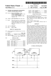
1
US006353433B1
(12) United States Patent
(10) Patent N0.:
Schumer
(54)
(76)
(,1)
(45) Date 0f Patent:
DIGITIZER INTERFACE
Inventor;
Notice,
US 6,353,433 B1
*Mar. 5, 2002
4,451,895 A
*
5/1984 Sliwkowski .............. .. 345/156
4,578,768 A
*
3/1986
Racine ...................... ..
4,677,258 A *
St” Redmond, WA (Us) 98053
4,716,542 A
This patent issued on a Continued pros_
4,763,356 A
4,821,029 A
*
*
8/1988 Day, Jr. et a1. ..
345/173
4/1989 Logan et a1. ............. .. 345/173
4,827,410 A
*
5/1989
.
.
.
6/1987 Kawashima et al.
178/18
A]fred L_ Schumer, 20522 NE 66th
12/1987 Peltz et al. .......... ..
Corren
178/18
15/64
..................... .. 345/179
ecunon apphcanoh ?led under 37 CFR
4,855,725 A * 8/1989 Fernandez
153911)’ and 1S shhleht to the twenty Year
4,933,514 A *
6/1990 Bowers .............. .. 178/18
Pawnt term PYOVISIOHS 0f 35 U-S-C154(a)(2)-
5,031,119 A *
5,049,862 A *
7/1991 Dulaney et a1.
9/1991 Dao et a1.
5,768,492 A
6/1998
Subject to any disclaimer, the term of this
patent is extended or adjusted under 35
_
345/173
345/179
Schumer ................... .. 345/173
OTHER PUBLICATIONS
U'S'C' 154(k)) by 0 days‘
_
*
345/185
BroWn, Edward; A WindoWing Mechanism for Structuring
_
_
_
Input; Oct. 3, 1985; Manuscript Thesis University of Tor
Tlhls Patent 15 Sublect to a termmal dls'
onto Library Department of Computer Science.
c a1mer.
(List continued on neXt page.)
(21) Appl- NOJ 09/098,034
(22) Filed:
Primary Examiner—Regina Liang
Jun_ 15’ 1998
Attorney, Agent, or Firm—Graybeal Jackson Haley
Related US. Application Data
(60)
(57)
Continuation of application No. 08/634,065, ?led on Apr.
A digitizer interface that translates the digitizer-speci?c
18: 1999: how Pat- NO- 577687492: which is a division of
reports into virtual areas of the digitizer Which may be
3511132223 NO‘ 07/716305’ ?led on Jun‘ 17’ 1991’ now
divided into speci?c regions or virtual tablets. Each region
permits the speci?cation of individual coordinate systems or
a
a a a
a a a
a a
a a a
a a a
a a a
a a a
a a
a a a
a a a
a a a
a a a
a a a
a a
a a a
a a a
a a .
(52) [15- Cl
(58)
345/173
Field of Search ............................... .. 345/173, 174,
mented on a host computer, in the digitizer, or in interme
diate electronics. The interface allows reports from digitiz
345/178, 179, 175, 176, 177, 156; 178/18.01,
18.03—18.09, 19.01, 20.01
(56)
ABSTRACT
ers of differing data output formats to be translated into a
standard format internal to the interface thereby isolating the
host processor from a given digitizer’s attributes. The inter
face may be con?gured to operate many digitizers from a
References Cited
single host.
US. PATENT DOCUMENTS
64 Claims, 13 Drawing Sheets
4,058,849 A * 11/1977 Fitzgerald et al.
IO
IO
-
I
| Region ,'
‘ Region ,
\
I
l
1'‘
II
\
Ill
I:
‘|l'“"""|
‘
I
II
“>|____l
“
\
\
I
\“
‘II
"I
I:
‘f'-"_J|
t
‘I
\____'|
Tablet
,
I
Flagron ,
\
l
\
I
\“
III
‘I
I’
1
ll
\l'""J|'
,
8
\____l|/
,'
I
I
l
‘I
I
US 6,353,433 B1
Page 2
OTHER PUBLICATIONS
Stevenson, David; (1990) “Absolute Pointing Device
Memory Structure” Macintosh Technical Notes #266.
Sample ‘ADBS’ Resource; (1989) Apple Macintosh Devel
oper Technical Support; Apple Computer Inc.
WIZ User’s Guide PC Edition.
Johnson, Timothy E.; (1990) “Closer to that pen—and—paper
feel” MacWeek.
Saarela,
Janne;
(1995)
ANSI
GKS
Standard
LCS04539—LCS04561.
Seiko Instruments USA Graphic Devices and Systems Divi
sion; (1990) Digitizing Tablet SoftWare User’s Guide
[LCS01583—LCS01617].
ADI Program Autodesk, Inc. (1996) Autodesk Device Inter
face/ADI Driver Development Kit Version 2.1.
ShaW, Richard Hale; (1989) Exploring the Key Functions of
the OS/2 Keyboard and Mouse Subsystems Microsoft Sys
tems Journal.
Gilol, Wolfgang K.; (1978) “Interactive Computer Graph
ics—Data Structures, Algorithms, Languages” Technical
University of Berlin and University of Minnesota
[LCS04976—05011].
User manual Hitachi SoftWare Utilities Version 1.01; (1988)
Hitachi America, Ltd.
The Microsoft Universal Pointing Device interface, Appli
cation Note, Revision 1.1 (1985) Microsoft Corporation.
Microsoft Mouse
Driver SoftWare
Interface
manual
[LCS07104—07124].
Tablet Extensions to the Mouse Driver Standard (1989)
LCS/Telegraphics [LCS06491—06506].
ming Reference; Publication 84—0850—202.
XMOUSE Programming Reference (1988) LCS/Telegraph
ics [LCS06338—06405].
IS Pensmith Drivers for DOS & WindoWs (1990) Kurta
MM 1201 and MM 961 Data Tablets Technical Refer
Summagraphics Corporation (1990) Tablet.com Program
Corporation.
ence(1984) Summagraphics Corporation LCS01352—01431.
BroWn, E. et al.; (1985) “WindoWs on Tablets as a Means of
SummaSketch Drivers/Utilities User’s Guide(1988) Sum
Achieving Virtual Input Devices” Computer Systems
magraphics Corporation.
Research Institute LCS05114—LCS05119.
SummaSketch User’s Guide (1985) \Summagraphics Cor
Buxton, William, et al.; (1986) “A Study in TWo Handed
Input”
Computer
Systems
Research
Institute
[LCS05108—05113], pp. 1—10.
Device Driver Adaptation Guide; (1990) Microsoft Win
poration.
doWs Device Development Kit Version 3.0 for the MS—DOS
or PC—DOS Operating System.
IBM Operating System/2 Programming Tools and Informa
tion Version 1.2 (1989) [LCS07419—07479].
MM II 1812 Graphics Tablet Technical Reference (1990)
Summagraphics Corporation.
The Autodesk Device Interface/ADI [LCS08315—08430].
ADI Driver Technical Reference LCS/Telegraphics
[LCS06484—08235].
* cited by examiner
U.S. Patent
Mar. 5,2002
Sheet 1 0f 13
US 6,353,433 B1
2
i
Single-User
FIG H
Network
U.S. Patent
Mar. 5,2002
Sheet 3 0f 13
US 6,353,433 B1
22"”
f
Device
/ '2
U.S. Patent
Mar. 5,2002
Sheet 4 0f 13
—"'
Status
No
Bit?
'
Yes
‘
US 6,353,433 B1
Coordinates?
Event
Adjust
Packet
Signs
Error
Process
Packet
Coordinates
I
Response
Process
Packet
Events
PM}, 41
.———
U.S. Patent
Mar. 5,2002
Sheet 5 0f 13
US 6,353,433 B1
@m
m
_
1IoQmb.
_
_
_
_
_
_
_
_
_
_
U.S. Patent
Mar. 5,2002
Sheet 8 0f 13
QQ
lmEBMdozw:
MJvUKw U
US 6,353,433 B1
U.S. Patent
Mar. 5, 2002
Sheet 10 0f 13
US 6,353,433 B1
Initialize
System
Host
Command?
NO
Procedure
Command?
No
1
l Yes
v
Read
Host
Command
Read
Procedure
Command
Process
Command
FIG, M)
U.S. Patent
Procedure
I
Mar. 5, 2002
Ygs
Rm?
No
US 6,353,433 B1
Sheet 11 0f 13
No
Ya
Queue
Packet
l
Enable Host
'l‘mnsmisaion
PM; U
U.S. Patent
Mar. 5,2002
Sheet 12 0f 13
Decode
D.
'I‘ablet to
. .
V
Rapon
Tablct
Enabled?
US 6,353,433 B1
No
PM} H2
US 6,353,433 B1
1
2
DIGITIZER INTERFACE
action to perform is decided Within the host computer by
translating the button state and location of the cursor into
knoWn areas of the video display or digitiZing tablet. If the
This is a continuation of the prior application Ser. No.
08/634,065, ?led Apr. 18, 1996 now US. Pat. No. 5,768,
492, Which is a divisional of prior application Ser. No.
07/716,305, ?led Jun. 17, 1991 noW abandoned.
action is based on translation of the action to a location
Within the video display, it is often referred to as a “menu
selection.” Alternatively, if the translation is performed
based on a location Within the digitiZer, it is referred to as a
BACKGROUND OF THE INVENTION
1. Field of the Invention
This invention relates in general to digitizing or data
10
“template command.” This latter method often requires a
“template” or physical menu positioned over the digitiZer
and depicting speci?c locations as menus or graphical
tablets (“digitiZers”) and in particular to interfacing digitiZ
images.
ers to host computers, their operating systems and applica
Regardless of the method used for translating the action,
considerable computing time by the host processor is
required Which is often directly related to the number of
tion programs.
2. Background Art
DigitiZers are computer peripherals that translate a user’s
hand motion into digital coordinates suitable for use by a
computer system. This translation is performed Within an X,
Y and possibly Z coordinate system Within the device
comprising an electronic grid over Which is placed a trans
ducer. This transducer may be pen-shaped (“stylus”), rect
angular or elliptical (“cursor” or “puck”) containing one or
more buttons. A microprocessor Within the digitiZer trans
lates the position of the transducer on the grid into digital
15
20
lation Which often constrains the translation to a speci?c
25
coordinates and reports its location and button status to the
host computer via a communications link Which is typically
a stream of serial bits.
Information transmitted to the host computer is encapsu
locations Within the video display or digitiZer Which must be
tested and translated. This computing time reduces the
amount of computing available to the host operating system
or its application programs. Furthermore, in the event the
translation is based upon locations Within the digitiZer,
information pertaining to the speci?c digitiZer such as its
physical siZe and con?guration must be used in the trans
30
lated in a speci?c format comprising multiple characters of
digitiZer and requires a different methodology for each
digitiZer siZe and type.
Heretofore, efforts to provide template translations have
been restricted to a small number of template areas and
implemented as a series of computer instructions speci?c to
the digitiZer and the actual location of each menu location on
the digitiZer surface. These instructions may be executed by
the microprocessor Within the digitizer or by the host
data Which are grouped into the button information and
coordinates. Each transmission of this information is
referred to as a “report.” Reports are sent either continuously 35 processor through the use of a dedicated translation appli
cation program. When done this Way, these methods are
or upon satisfaction of some de?ned combination of button
referred to as “hard-coded” templates and are determined at
states or distance moved. The rate at Which reports are sent
from the digitiZer to the host computer varies considerably
depending upon the particular digitiZer, the speci?cation of
the button states or programmed con?guration and may
range up to several hundred times per second.
In addition to transmitting coordinate data to the host
computer, digitiZers often accept commands from the host
computer governing the operating characteristics of the
digitiZer. These commands are usually encoded in individual
characters Which collectively comprise a command and its
arguments. Examples of such commands include scaling the
40
Without redesigning the digitiZer or recreating the applica
tion program on the host processor.
Hard-coded templates necessarily restrict template trans
45
user the ability to modify or even create their oWn templates.
50
are transmitted or specifying the type or format of informa
tion sent With each report.
Upon receipt of each character of data from the digitiZer,
the host system is interrupted from the task it Was engaged
in and processes the data by combining it With previous data
Furthermore, such templates are restricted to the speci?c
digitiZer, are often expensive to develop or purchase and
require considerable host processor computing time result
ing in loWer system throughput manifested by sloWer appli
cation response time.
55
SUMMARY OF THE INVENTION
characters until a complete report has been received. It then
The principal object of the present invention is to provide
a method of de?ning, manipulating and processing large
translates this data and takes appropriate action depending
on the information contained in the report, e.g. button
presses or releases or coordinate values. Such actions may
include moving a visible cursor on the video display
attached to the host computer or selecting some action
depending on the location and status of one or more buttons.
lation activities to the time of digitiZer manufacture or
creation of the application program by experienced com
puter professionals and do not afford the typical computer
digitiZers axis to an absolute value or resolution in counts
per unit of measurement, selecting the rate at Which reports
the time of digitiZer manufacture or creation of the appli
cation program or template. Once created, these instructions
are dependent upon the knoWn digitiZer attributes and the
locations to be translated. Hence, they cannot be changed
numbers of template locations on a digitiZer in a manner
60
Which signi?cantly reduces host processor computation. The
templates may be created and changed dynamically by
computer users and application programs and the application
programs are not restricted to any speci?c digitiZer or host
DigitiZers are frequently used to draW information into an 65 processor.
In ful?llment and implementation of the previously
application program or select some application command
recited object, a primary feature of the invention resides in
via a button press or release. The determination of Which
US 6,353,433 B1
3
4
the de?nition and methodology of an advanced digitizer
embodiment implemented as discrete microprocessor
circuit, the ?rmWare instructions to the preferred embodi
ment and ?nally an eXample of using the Interface Within an
application conteXt. The Interface details the conceptual
methodology and speci?c command structure While the
circuit description discloses one possible implementation for
an IBM PC/AT personal computer. The ?rmWare description
interface (the “Interface”) Which allows the dynamic cre
ation and manipulation of template areas non-speci?c to any
digitizer or host processor. Embedded in this Interface is a
de?ned methodology for translating digitiZer-speci?c
reports into virtual areas of the digitiZer Which are accessed
as speci?c numbered regions. Each of these regions may
possess various attributes Which collectively permit the
includes block ?oWcharts of computer instructions for com
bining the Interface and microprocessor circuit and the
application eXample demonstrates their use in creating a
speci?cation of individual coordinate systems or stored
sequences of commands.
template menuing system.
An additional feature of the invention includes a device
Interface Description
independent Interface to the digitiZer Which isolates the
computer user or application program from a given digitiZ
er’s attributes and permits creation of one set of instructions
Which may be eXecuted across any number of digitiZers or
host processor systems. The invention includes a tablet
addressing feature Which alloWs many tablets to be con
Con?guration
15
of the Interface is the ability to execute Interface commands
Without modi?cation across either con?guration through the
use of tablet addresses (see Packet Protocol beloW).
The single-user con?guration 2 of the Interface may be
nected to a single computer or a netWork of computers and
operated independently of each other.
Finally, the preferred embodiment of the invention uti
liZes a dedicated microprocessor to implement this advanced
digitiZer Interface Which signi?cantly improves host proces
sor throughput and application response time (the “Circuit”).
implemented as a discrete microprocessor circuit as
25
an EIA-232 serial communications link.
The netWork con?guration 4 of the Interface may be
implemented across a number of Well-known, industry
standard netWork topologies and architectures. HoWever, the
preferred embodiment utiliZes the nine-bit serial communi
cations mode inherent in the microprocessor of the circuit
performance considerations.
BRIEF DESCRIPTION OF THE DRAWINGS
(as described beloW) utiliZing the topology and architecture
of the BITBUS Interconnect Serial Control Bus across an
35
Interconnect Serial Control Bus Speci?cation” (Intel
Corporation, 1988). The EIA-485 serial communications
FIG. 3. illustrates the relationships among the three coor
standard is fully described in “Standard for Electrical Char
acteristics of Generators and Receivers for Use in Balanced
dinate systems embodied in the present invention;
FIG. 4. is a ?oWchart depicting a packet decoding pro
Digital Multipoint Systems” (Electronics Industry
Association, 1983).
Logical Layers
cess;
45
the present invention.
FIG. 8. is a schematic of the Programmed Input/Output
circuit for the present invention.
55
The tablet layer 8 provides the ?rst true level of abstrac
of the present invention;
tion to an application program and is consistent across all
FIG. 12. is a ?oWchart depicting interrupt event process
devices. It is the logical level at Which device-independent
ing of the present invention;
FIG. 13. illustrates an eXample template menuing system
created With present invention;
tions including: a description of the Interface, the preferred
formats and physical characteristics into a device
independent format internal to the Interface. The device
layer may be queried for certain attributes but cannot be
changed.
FIG. 11. is a ?oWchart depicting command eXecution unit
DESCRIPTION OF THE INVENTION
The description of the invention encompasses four sec
Referring to FIG. 2, the Interface supports three logical
layers Which provide an increasing level of abstraction from
the actual digitiZer: device 6, tablet 8 and region 10.
The device layer 6 represents the physical device or
digitiZer Whose properties are established at the time of
manufacture. Since digitiZers vary greatly both in terms of
physical characteristics and output formats, the device layer
provides the ?rst level of abstraction by translating both the
FIG. 9. is a schematic of the Bus Interface Unit circuit for
the present invention.
FIG. 10. is a ?oWchart depicting the main program loop
of the present invention;
EIA-485 serial communications link. This serial bus stan
dard is Well-known and fully described in “The BITBUS
digitiZer layers embodied in the present invention;
FIG. 5. is a block schematic of four circuits for the present
invention.
FIG. 6. is a schematic of the Central Processing Unit
circuit for the present invention.
FIG. 7. is a schematic of the Serial Input/Output circuit for
described beloW (see “Circuit”) or Within the microproces
sor of the digitiZer connected directly to a host processor via
This microprocessor may be implemented as either an
input-output processor for the host system, dedicated exter
nal controller or a replacement to the digitiZer microproces
sor itself; the choice of Which is governed by cost and
FIG. 1 illustrates the single-user and netWork con?gura
tions embodied in the present invention;
FIG. 2 illustrates the relationships among the conceptual
Referring to FIG. 1, the Interface supports tWo con?gu
rations: single-user 2 and netWork 4. The single-user 2
con?guration supports one digitiZer per system While the
netWork con?guration 4 supports up to siXteen digitiZers
inter-connected to a single host system. An important feature
control over the Interface is eXercised and incorporates a
device-independent coordinate system Which may be scaled
by an application program and Within Which regions are
65
created.
The region layer 10 provides the highest level of abstrac
tion to the application program and from Which all user
US 6,353,433 B1
5
6
events are generated. The region layer consists of discrete
areas de?ned Within the tablet layer Which may be assigned
speci?c attributes such as event masks, de?nable coordinate
signi?cant-bit of each Word. This phase bit is a logical-one
packet Word. This alloWs both the Interface and host pro
systems or stored sequences of Interface commands
cessor to detect the start of each packet from a stream of data
executed upon some user-event.
as Well as the recognition of invalid packets.
at the start of each packet and Zero for each successive
The siZe and format of each packet depends on the packet
type of Which the preferred embodiment of the Interface
supports three: command, response and event packets. Com
Coordinate Systems
A “coordinate system” is used to identify a point relative
to a horiZontal, vertical and occasional Z-axis. All coordi
nate systems have an origin and may be transformed, scaled
mand packets are transmitted from the host processor to the
Interface and contain both commands and arguments. Upon
or rotated. Each point on a tablet can be located by means
execution of the command, the Interface sends a response
packet back to the host processor containing both an error
of a unique pair of X and Y coordinates. Referring to FIG.
3, the Interface supports three such coordinate systems:
device 12, tablet 14 and regional 16.
The device coordinate system 12 is dependent upon the
physical properties of each digitiZer and cannot be changed
by an application program. HoWever, properties of the
device coordinate system can be queried including the
code and arguments, if appropriate. Finally, event packets
15
are generated by the Interface in response to user-actions
such as button presses, button releases or movement of the
cursor Within a speci?c region.
The three layers of the Interface accept commands, gen
erate responses and, in the case of regions, generate events
based on a 15-bit addressing scheme embedded in each
device axis, extents and resolution.
The tablet coordinate system 14 is super-imposed on all
devices that the Interface supports and is used to de?ne
regional coordinate systems and upon Which all tablet geom
packet. The address is alWays contained in the second Word
of each packet regardless of packet type and is formatted as
folloWs:
|0 |T | TABLETI R |
REGION
Where:
Tablet group bit (bit 14) indicating the address is directed to a
group of tablets the number of Which is contained in the tablet
address.
TABLET
Tablet address (bits 10-13) indicating the address of the tablet or
group to Which a command or response is directed or generated.
R
Region group bit (bit 9) indicating the address is directed to a
group of regions the number of Which is contained in the region
REGION
Region address (bits 0-8) indicating the address of the region or
address.
group to Which a command or response is directed or an event
generated.
etries are calculated. The tablet coordinate system extents
This addressing scheme is analogous to a post of?ce box
address in Which the tablet address refers to the post office
may be scaled 18 either by explicitly setting the extents or
implicitly by setting the resolution in lines per inch. The
and the region address to the particular box. In this regard,
tablet coordinate system may not be tansformed or rotated 45
commands
and responses at the tablet layer require only the
and cannot be changed once one or more regions have been
tablet
address—the
region address ignored. Similarly, region
de?ned.
commands, responses and events require both the tablet and
Regional coordinate systems 16 (also referred to as local
coordinate systems) are the most poWerful and versatile
region address.
coordinate systems supported by the Interface and may be
scaled 20, transformed 22 or rotated 24. Prior to use, they
must be explicitly created by specifying the bounding rect
angle in tablet coordinates and may be destroyed explicitly
by closing each region or implicitly When closing the tablet.
Commands addressed to the device layer are speci?ed
With a tablet address, rather than device address, in order to
55
Once created, a regional coordinate system may be scaled
by changing the extents or resolution, transformed by mov
ing the origin or rotated by specifying a counter-clockwise
rotation factor in degrees. Each of these properties may also
facilitate the allocation of multiple logical tablets per physi
cal device. This allocation may be performed by appropriate
commands from the host processor and requires partitioning
the physical device into one or more logical areas. Each area
responds to commands directed to a particular tablet and
be queried, generating response packets Whose format is
generates event packets using tablet addresses for Which
dependent on the information requested.
Which they have been assigned (see Interface Description:
Event Processing beloW).
Packet Protocol
All communication betWeen the Interface and host pro
cessor is accomplished via packets Which comprise tWo or
more 16-bit Words. Each packet is delineated and synchro
niZed through the use of a phasing bit in the most
65
The format of a command packet issued to the Interface
from the host processor is as folloWs:
US 6,353,433 B1
P
0
COMMAND
|
0 T TABLET| R |
0
0
0
0
0
REGION
(ARGUMENT 1)
(ARGUMENT 2)
(ARGUMENT 3)
(ARGUMENT 4)
where:
P
Phase bit (bit 15) which is set for the ?rst packet word and clear
COMMAND
Numerical command identi?er (bits 7-13) corresponding to one
T
Tablet group (bit 15) address.
TABLET
Tablet address (bits 10-13) to which the command is issued.
R
Region group (bit 9) address.
for all other words.
of the Interface commands.
REGION
Region address (bits 0-8) to which the command is issued —— Zero
ARGUMENT 1
if command addresses only the tablet.
Optional argument dependent on the command speci?ed. Not
present if the command does not take one or more arguments.
ARGUMENT 2
Optional argument dependent on the command speci?ed. Not
present if the command does not take two or more arguments.
ARGUMENT 3
Optional argument dependent on the command speci?ed. Not
present if the command does not take three or more arguments.
ARGUMENT 4
Optional argument dependent on the command speci?ed. Not
present if the command does not take four or more arguments.
Command packets comprise between two and six words.
Extra arguments to command packets are ignored while
though this capability can be over-ridden.
insuf?cient arguments result in packet rejection by the
Response packets can take one of two forms—command
acknowledgement or command response—depending on the
Interface. Typically, a host processor device driver will
format the packet correctly for an application program
particular command and whether it executed successfully.
Response packets aare formatted as follows:
P S
0
0
0
0
0
COMMAND
TABLET | R |
I
RESULT
REGION
(ARGUMENT 1)
(ARGUMENT 2)
(ARGUMENT 3)
(ARGUMENT 4)
where:
P
Phase bit (bit 15) which is set for the ?rst packet word and clear
RESULT
for all other words.
Status bit (bit 14) which is set for a response packet.
Numerical command identi?er (bits 7-13) corresponding to one
of the Interface commands.
Result code (bits 0-6) which is Zero if the command executed
TABLET
Tablet address (bits 10-13) to which the command is issued.
S
COMMAND
successfully or an error code if not.
R
Region group (bit 9) address.
REGION
Region address (bits 0-8) to which the command is issued —— Zero
ARGUMENT 1
if command addresses only the tablet.
Optional argument dependent on the command speci?ed. Not
present if the command does not return one or more arguments
or an error occurred.
ARGUMENT 2
Optional argument dependent on the command speci?ed. Not
present if the command does not return three or more arguments
or an error occurred.
ARGUMENT 3
Optional argument dependent on the command speci?ed. Not
present if the command does not return three or more arguments
or an error occurred.
US 6,353,433 B1
10
-continued
ARGUMENT 4
Optional argument dependent on the command speci?ed. Not
present if the command does not return four or more arguments
Commands Which execute successfully and do not request
information from the Interface never return their
10
dependent on Whether coordinates are present and can
comprise either tWo or four Words.
arguments—only the command and result codes in the ?rst
Packet Decoding
packet Word and the address to Which the command Was
Referring to FIG. 4, one possible method of the packet
decoding for a host processor is illustrated. The processing
loop begins With the receipt of a packet Word Which is ?rst
checked for the presence of the phasing bit in the most
signi?cant bit. If it is set, the second in most-signi?cant bit
is then checked to determine Whether the remaining packet
directed in the second. The packet size for these packets is
alWays tWo Words.
Similarly, commands Which execute and result in an error 15
never return arguments regardless of the command type—
only the command and non-zero result code in the ?rst
packet Word and the address to Which the command Was
directed in the second. The packet size for these packets is
alWays tWo Words.
Words constitute an event or command response packet.
If the status bit is set, the packet is a command response
and the error code is tested for a non-zero value. Azero error
code indicates the command requested executed success
Finally, commands Which request information from the
fully and the arguments, if requested by command context,
Interface and execute successfully return the command and
zero result code in the ?rst packet Word, the address to Which
Which are generated from the region layer in response to
are present and may be interpreted. Otherwise, an error
occurred, the arguments are not present and the command
code should be examined to determine Which command did
not execute. Error packets alWays return the command and
error code in the ?rst packet Word, and the address of the
command in the second.
If the status bit is clear, the packet is an event packet
Which contains the event in the remaining bits of the ?rst
the command Was directed in the second and one or more 25
arguments in the successive packet Words. The packet size
for these packets is dependent upon the particular command
and comprise between three to six Words.
The most common packets encountered are event packets
some user-action such as pressing or releasing a button and
packet Word, the address of the packet in the second packet
moving the cursor. Event packets take tWo forms depending
Word and the X and Y coordinates, if present, in the third and
on Whether coordinate data has been enabled. The format for
event packets is as follows:
four packet Words. The Coordinate bit (bit 8) Will be set in
the ?rst packet Word (event Word) if the coordinates are
P sx|Y|0|0Rc|UP|DOWN
O
0
0
O
TABLET
0
REGION
(x COORDINATE)
(Y COORDINATE)
Where:
P
Phase bit (bit 15) Which is set for the ?rst packet Word and clear
S
for all other Words.
Status bit (bit 14) Which is clear for an event packet.
X
Y
Sign bit (bit 13) for the X coordinate (if present).
Sign bit (bit 12) for the Y coordinate (if present).
R
Coordinates (bit 9) are relative from the last valid event.
C
UP
DOWN
TABLET
REGION
Coordinates present (bit 8); used in conjunction With relative bit.
Button(s) 1-4 Were released (bits 1, 3, 5, and 7 respectively).
Button(s) 1-4 Were pressed (bits 0, 2, 4, and 6 respectively).
Tablet address (bit 10-13) issuing the event.
Region address (bits 0-8) issuing the event.
X COORDINATE
If coordinate bit set in ?rst packet Word, contains the X coordinate
Where the event occurred.
Y COORDINATE
If coordinate bit set in ?rst packet Word, contains the Y coordinate
Where the event occurred.
60
present and the Relative bit (bit 9) Will be set if the
coordinates are relative to the last reported position. The
Unlike response or command packets, event packets do
not contain command or error codes but instead a bit mask
indicating the type of events Which occurred and Whether the
packet contains coordinate data. Event packets are only
generated from Within regions and therefore the region
address is alWays valid. The packet size for event packets is
coordinate values are further modi?ed With the presence of
the X and Y sign bits (bits 13 and 12) in the event Word if
65
the coordinates are negative.
Decoding the coordinates of the event packet requires
testing for the presence of the Coordinate bit in the event