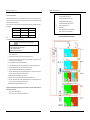
1
NS3000 Series User Manual
Rev. 01
NS3000 Series User Manual
UPS NS3000 10-20-30kVA
USER Manual
-1-
-2-
Rev. 01
NS3000 Series User Manual
Rev. 01
NS3000 Series User Manual
Components that can be maintained by user
Safety Precautions
This manual is about the installation and operation of NS3000 Series UPS (Hereinafter referred to
as UPS).
Please carefully read this manual prior to installation.
The UPS must be debugged and maintained by the engineer commissioned by the manufacturer or
the agent. Otherwise, human safety may be endangered and the damage of UPS shall not belong to the
warranty scope.
UPS is only used for commercial / industrial purpose and cannot be used as power of life support
equipment.
All the equipment maintenance and servicing procedures involving internal access need special tools
and should be carried out only by trained personnel. The components that can only be accessed by
opening the protective cover with tools cannot be maintained by user.
This UPS full complies with “IEC62040-1-1-General and safety requirements for use in operator
access area UPS”.Dangerous voltages are present within the battery box. However, the risk of
contact with these high voltages is minimized for non-service personnel. Since the component with
dangerous voltage can only be touched by opening the protective cover with a tool, the possibility of
touching high voltage component is minimized. No risk exists to any personnel when operating the
equipment in the normal manner, following the recommended operating procedures in this manual.
APPLICABLE STANDARDS
Battery Voltage Higher Than 400Vdc
This product complies with 2006/95/EC - CE 73/23 & 93/68 (low voltage safety) and 2004/108/EC
89/336 (EMC) , and EMC standards of Australia and New Zealand (C-Tick) , and the following UPS
product standards:
*IEC62040-1-1-General and safety requirements for use in operator access area
*IEC/EN62040-2 EMC requirements CLASS C3
*IEC62040-3 Performance requirements and test methods
Continued compliance requires installation in accordance with these instructions and the use of
manufacturer approved accessories only.
All the battery maintenance and servicing procedures involving internal access need special tools or
keys and should be carried out only by trained personnel.
SPECIAL CARE SHOULD BE TAKEN WHEN WORKING WITH THE BATTERIES ASSOCIATED
WITH THIS EQUIPMENT. WHEN CONNECTED TOGETHER, THE BATTERY TERMINAL
VOLTAGE WILL EXCEED 400Vdc AND IS POTENTIALLY LEATHAL.
Battery manufacturers supply details of the necessary precautions to be observed when working on,
or in the vicinity of, a large bank of battery cells. These precautions should be followed implicitly at all
times. Particular attention should be paid to the recommendations concerning local environmental
conditions and the provision of protective clothing, first aid and fire-fighting facilities.
WARNING- High earth leakage current
Earth connection is critical before connecting the input supply (include both utility supply and
battery) . This equipment must be earthed in accordance with local electrical authority codes of
practice.
Earth leakage current exceeds 3.5 mA and is less than 1000 mA.
Transient and steady-state earth leakage currents, which may occur when starting the equipment,
should be taken into account when selecting instantaneous RCCB or RCD devices.
Residual Current Circuit Breakers ( RCCBs) must be selected insensitive to DC unidirectional pulses
( class A ) and transient current pulses ( RCCBs) .
Note it that the earth leakage currents of the load will also flow across UPS RCCB or RCD.
Warning: Back feed Protection
Backfeed protection, (optional), is provided to isolate the static switch if excessive voltage is present at the
bypass input when the bypass source is deenergized. If this function is not installed and enabled , there must be
a warning label on the external bypass switch to remind the operator of the connection. The warning on label
should be: Isolate the UPS before operating this part.
-3-
-4-
Rev. 01
NS3000 Series User Manual rev.01
CONTENTS
Chapter 1 Quick Start .................................................................................. 8
1.1 Introduction ................................................................................................................................................... 8
1.2 Initial Checking.............................................................................................................................................. 8
1.3 Environment Checking ................................................................................................................................... 8
1.4 Installation Checking...................................................................................................................................... 8
Chapter 2 Installation Guidance ................................................................... 9
2.1 Introduction ................................................................................................................................................... 9
2.2.2 Battery Room ................................................................................................................................10
2.2.3 Storing ..........................................................................................................................................10
2.3 Disassembly, Initial Checking and Positioning .............................................................................................. 10
2.3.1 System Packing .............................................................................................................................10
2.3.1.1 Remove the ups from the pallet .................................................................................................11
Fig 2-1 UPS Packing Diagram ................................................................... 11
3.2.3 Auto-Restart Mode ........................................................................................................................29
3.2.4 Bypass Mode.................................................................................................................................29
3.2.5 Maintenance Mode ........................................................................................................................29
3.2.6 ECO Mode ....................................................................................................................................29
3.2.7 Frequency Converters Mode ..........................................................................................................29
3.2.8 Parallel connection redundancy mode.............................................................................................30
3.3 Battery Management .................................................................................................................................... 30
3.3.1 Normal Function ...........................................................................................................................30
3.3.2 Advanced Functions (Battery Self-checking and Maintenance) .......................................................30
3.4 Battery Protection ........................................................................................................................................ 30
Chapter 4 Installation of Parallel Operation System .................................... 31
Chapter 5 Operating Procedures................................................................ 33
5.1 Power Switches............................................................................................................................................ 33
5.2 UPS Start-up ................................................................................................................................................ 33
2.3.2 UPS Composition..........................................................................................................................12
5.2.1 Normal Mode Start ........................................................................................................................33
2.3.3 Operation Space ............................................................................................................................12
5.2.2 Battery Module Start (Only Applicable for the UPS with Battery Cold Start Elements) ..............35
2.3.4 Front and Back Access...................................................................................................................12
5.3 Procedure for Switching between Operation Modes....................................................................................... 35
2.3.5 Final Positioning ...........................................................................................................................12
5.3.1 Procedure for Switching the UPS into Battery from Normal Mode ..................................................35
2.3.6 Cable Entry ...................................................................................................................................12
5.3.2 Procedure for Switching the UPS into Bypass from Normal Mode ..................................................35
2.4 Protective Devices........................................................................................................................................ 12
5.3.3 Procedure for Switching the UPS into Normal from Bypass Mode ..................................................36
2.4.1.1 Rectifier and Bypass Input Supply of the UPS .............................................................................13
5.3.4 Procedure for Switching the UPS into a Maintenance Bypass from Normal Mode ...........................36
2.4.1.2
Beakfeed Protection. ................................................................................................................14
5.3.5 Procedure for Switching the UPS into Normal from a Maintenance Bypass Mode ...........................36
2.4.3 Battery ..........................................................................................................................................15
2.5.1 Maximum stable state current and configuration of minimum cable system .....................................15
5.4 Procedure for Completely Powering down a UPS.......................................................................................... 36
5.5 EPO Procedure............................................................................................................................................. 37
5.6 Language Selection ...................................................................................................................................... 37
5.7 Control Password ......................................................................................................................................... 37
2.5.2 Cable Connection ..........................................................................................................................16
Chapter 6 Operator Control and Display Panel ........................................... 38
2.4.3 UPS Output ...................................................................................................................................15
2.5 Power Cables ............................................................................................................................................... 15
2.5.3 Connection for Battery...................................................................................................................17
2.6 Control and Communication Cabling ............................................................................................................ 20
2.6.1 Dry Contact Interface of Battery and Environmental Temperature Detection (Optional)...................20
2.6.2 Remote EPO Input Port (Optional) .................................................................................................21
2.6.3 Generator Input Dry Contact (Optional) .........................................................................................22
2.6.4 BCB Interface (Optional) ...............................................................................................................22
2.6.5 Battery Warning Output Dry Contact Interface (Optional)...............................................................23
2.6.6 General Warning Output Dry Contact Interface (Optional)..............................................................23
2.6.7 Mains Failure Warning Output Dry Contact (Optional) ...................................................................24
2.6.8 RS232-RS485 Port and SNMP Card Port .......................................................................................24
2.7
Installation Diagram .................................................................................................................................. 25
Chapter 3 Operations ................................................................................ 27
3.1 Introduction ................................................................................................................................................. 27
3.1.1 Principle........................................................................................................................................27
3.1.2 Bypass ..........................................................................................................................................28
3.1.3 Battery Temperature Compensation ...............................................................................................28
3.2 Operation Mode ........................................................................................................................................... 28
3.2.1 Normal Mode ................................................................................................................................29
3.2.2 Battery Mode ................................................................................................................................29
6.1 Introduction ................................................................................................................................................. 38
6.1.1 LED Indicator ...............................................................................................................................39
6.1.2 Audible Alarm (buzzer) .................................................................................................................39
6.1.3 Functional Keys ............................................................................................................................40
6.2 LCD Display Type ....................................................................................................................................... 40
6.2.1 Default Display .............................................................................................................................40
6.2.2 Data Display..................................................................................................................................40
6.2.3 Setting Display ..............................................................................................................................41
6.2.4 Function Display ...........................................................................................................................41
6.2.5 State Display .................................................................................................................................41
6.2.6 Confirm Display ............................................................................................................................42
6.2.7 History Record Display..................................................................................................................42
6.3 Detailed Description of Menu Items.............................................................................................................. 43
6.4 Alarm List ................................................................................................................................................... 44
Chapter 7 Maintenance.............................................................................. 45
7.1 Instruction of Maintenance Operation ........................................................................................................... 45
7.1.1 Precautions....................................................................................................................................45
7.1.2 Instruction to Bypass Module.........................................................................................................45
Chapter 8 Product Specification ................................................................. 46
8.1 Applicable Standards.................................................................................................................................... 46
-5-
-6-
NS3000 Series User Manual rev.01
NS3000 Series User Manual rev.01
8.2 Environmental Characteristics ...................................................................................................................... 46
Table 8-2........................................................................................................................................................... 46
8.3 Mechanical Characteristics ........................................................................................................................... 46
8.4 Electrical Characteristics (Input Rectifier)..................................................................................................... 47
8.5 Electrical Characteristics (Intermediate DC Link).......................................................................................... 47
8.6 Electrical Characteristics (Inverter Output).................................................................................................... 48
8.7 Electrical Characteristics(Bypass Mains Input).............................................................................................. 49
8.8 Efficiency .................................................................................................................................................... 49
Chapter 1 Quick Start
1.1 Introduction
This chapter introduces the basic principles for UPS installation and debugging, so that personal service can install
and debug UPS quickly.
1.2 Initial Checking
Perform the following checking operations prior to the UPS installation.
1.
Visually examine if there is any damp, water, or damage inside and outside the UPS packing, products and battery
equipments due to the transportation. Report any such damage to the shipper immediately.
2.
Verify the product label and confirm the correctness of the equipment. The equipment label is attached on the panel
behind front door. The UPS model, capacity and main parameters are marked on the label.
3.
Verify correctness of the accessories. If there is any mistake for accessories, contact with shipper or provider.
1.3 Environment Checking
Before installing UPS, please check these items as below:
1.
Is the UPS operation environment temperature above 25°C? If so, please add cooling equipments.
Note: Environment temperature above 20°C, battery life will reduce to half when environment
rise each 10°C.
temperature
2.
Is the UPS operation environment temperature below 0°C? If so, please add heaters.
3.
Is the UPS operation environment humidity is above 90% Is there any condensing? If so, please add additional
protection.
4.
In the UPS operation environment, is there any sunshine shining in directly or life-form coming in? If so, please add
additional protection.
5.
In the UPS operation environment, is there any dust, combustible or explosive gas? If so, please add additional
protection.
1.4 Installation Checking
After finishing installation, please check these items as below:
-7-
1.
Is UPS installed on the flame-retardant materials?
2.
Are all cables connected exactly?
3.
Are all grounded system connected according to the manual?
4.
Is there enough operation space around UPS?
5.
Please confirm all UPS external terminals are fastened, the moment should meet requirements.
6.
Please confirm that there are no screws, cables and other conductor left in the UPS. If there is, please take out.
-8-
NS3000 Series User Manual rev.01
NS3000 Series User Manual rev.01
2.2.2 Battery Room
Chapter 2 Installation Guidance
2.1 Introduction
This chapter introduces UPS installation, it provide normal installation steps and ideas. Please installation engineers
operate according to each place difference,
Warning-Installation can only be done by authorized engineers
1. Do not apply electrical power to the UPS equipment before the approval of commissioning
engineer.
2. The UPS should be installed by a qualified engineer in accordance with the information contained
in this chapter.
The battery will generate some amount of hydrogen and oxygen at the end of charging, so the fresh air volume of
the battery installation environment must meet EN50272-2001 requirements. The ambient temperature of the battery
must be stable. Ambient temperature is a major factor in determining the battery capacity and life. The nominal operating
temperature of battery is 20°C. Operating above this temperature will reduce the battery life, and operation below this
temperature will reduce the battery capacity. If the average operating temperature of battery is increased from 20ºC to
30ºC, then the service life of the battery will be reduced by 50%. If the operating temperature of the battery is above 40ºC,
then the battery service life will be decreased in exponent rate. In a normal installation, the battery temperature is
maintained between 15°C and 25°C. Keep batteries away from heat sources or air outlets.
If external batteries are to be used, a battery protection device (a DC circuit breaker) must be mounted as close as
possible to the batteries, and the connecting cables should be as short as possible.
2.2.3 Storing
If the equipment not be installed immediately, it must be stored in a room so as to protect it against excessive
humidity and heat sources. The battery needs to be stored in dry and cool place with good ventilation. The most suitable
storage temperature is 20 ºC to 25ºC.
Note: 3-Phase 4-Wire Input Power is required
2.3 Disassembly, Initial Checking and Positioning
The standard UPS can be connected to TN, TT AC distribution system (IEC60364-3) of 3-phase
5-wire.For IT system please contact us.
WARNING: battery hazards
SPECIAL CARE SHOULD BE TAKEN WHEN WORKING WITH THE BATTERIES ASSOCIATED
WITH THIS EQUIPMENT. When connecting the battery, the battery terminal voltage will exceed
400Vdc and is potentially lethal.
l
Eye protection should be worn to prevent injury from accidental electrical arcs.
l
Remove rings, watches and all metal objects.
l
Only use tools with insulated handles.
l
Wear rubber gloves.
l
If a battery leaks electrolyte, or is otherwise physically damaged, it must be replaced, stored in a
container resistant to sulfuric acid and disposed of in accordance with local regulations.
l
If electrolyte comes into contact with the skin, the affected area should be washed immediately
with water.
Check the packaging first upon the arrival of product to see if there is any damage; open the packaging to check the
equipment; report any such damage to the shipper immediately.
2.3.1 System Packing
Remove the carton box and the plastic film first, thensee.Durig the procedure under descript
scratch the product.
2.2.1 Distribution Room
The UPS is designed for indoor installation, which shall be located in a clean environment with adequate ventilation
to keep the environmental temperature within the required specification. The UPS uses forced convection cooling by
internal fans. Cooling air enters the module through ventilation grills located at the front part or in front and botton
(NS3030) of the cabinet and exhausted through grills located in the rear part of the cabinet. Please do not block the
ventilation holes.
If necessary, a system of extractor fans should be installed to aid cooling-air flow. An air filter should be used when
the UPS is to operate in a dirty environment and should be regularly cleaned to maintain airflow.
Note: The UPS should be installed on a cement surface or other surface that is not combustible.
-9-
-10-
Be careful not
NS3000 Series User Manual rev.01
NS3000 Series User Manual rev.01
REMOVING THE UPS FROM THE PALLET
Verify the product label and confirm the correctness of the equipment. The equipment label is attached on the back
of front door. The UPS model, capacity and main parameters are marked on the label.
Warm Tips: Please dispose the wasted materials in accordance with environmental protection requirements
after disassembly.
Fig 2-1 UPS Packing Diagram
To prolong the service life, the place chosen for the UPS must guarantee:
CAUTION! TO AVOID HARMING PEOPLE AND/OR DAMAGING THE EQUIPMENT, FOLLOW
CAREFULLY THE FOLLOWING INSTRUCTIONS.
SOME OF THESE INSTRUCTIONS NEED TO BE CARRIED OUT BY TWO PEOPLE.
l
Easy wiring
l
Sufficient space for operation
l
Air sufficient enough to dispel heat produced by UPS
l
Against ambient corrosive gases
l
Against excessive humidity and heat sources
l
Against dust
l
With the current fire prevention requirements
l
The operating environment temperature is within 20 -25 . The batteries are at maximum efficiency in this
temperature range (for information about the battery storage and transportation as well as the environment, please
refer to table 8-2)
2.3.2 UPS Composition
Cut the straps and remove the cardboard box by
sliding it upwards.
§
Remove the 2 brackets securing the UPS to the pallet by unscrewing the
screws.
10KVA~30KVA cabinet
2.3.3 Operation Space
As UPS has no ventilation grills at either side, no clearances are required for the sides.
To enable routine tightening of power terminations within the cabinet, it is recommended that clearance around the
front and back of the equipment should be sufficient to enable free passage of personnel with the doors fully opened.
The back door of the cabinet is more than 800mm from the wall or other cabinets.
Distance from the back ≥ 200mm
§
The previously removed brackets can also be used as slides. Secure the slides to the pallet by using the type A screws, making sure
they are aligned with the wheels.
2.3.4 Front and Back Access
The component layout of the UPS supports front and back access for servicing, diagnosing and repairing the UPS,
thus reducing the space requirement for side access.
2.3.5 Final Positioning
When the equipment has been finally positioned, ensure the adjustable feet is set so that the UPS will remain
stationary and stable.
2.3.6 Cable Entry
A lower incoming line is used for 10KVA~30KVA UPS.
2.4 Protective Devices
§
§
§
Screw the brake rod completely, so to separate it from the pallet
Make sure that the door is firmly closed.
CAUTION! Push the UPS from the rear with great care. Given the weight of the equipment, this operation needs to be carried out
by two peopleNOTE : It is recommended to keep all parts of the packaging for further use
For safety concerns, it is recommended to install external circuit breakers or other protective devices for the input
AC supply of the UPS system.
We suggest to choose the input automatic break Bigger than internal automatic Breaker and D curve for the selectivity
with internal UPS protection.
This section provides generic practical information for qualified installation engineers. The installation engineers
should have the knowledge of the regulatory wiring standards, and of the equipment to be installed.
Tip: Dismantle the bolts that connect the cabinet and wooden pallet after disassembly, then lift the cabinet to installation position. The
dismantlement should be careful so as not to scratch the body.
-11-
-12-
NS3000 Series User Manual rev.01
NS3000 Series User Manual rev.01
2.4.1.1 Rectifier and Bypass Input Supply of the UPS
2.4.1.2 Backfeed Protection.
Install suitable protective devices in the distribution unit of the incoming mains supply, considering the power cable
current-carrying capacity and overload capacity of the system. Generally, the magnetic circuit breaker with IEC60947-2
tripping curve C (normal) at the 125% of the current listed in table 2-1 is recommended. Whith common input we suggest
tripping curve d
Put a label on all primary power isolators installed remote from the UPS area. One label is supply
Before working on this circuit
- Isolate Uninterruptible Power System (UPS)
Note
- Then check for Hazardous Voltage between all terminals
For IT power network system, 4-pole protective device must be installed on the external input distribution of the
UPS.
including the protective earth
Earth leakage current
If protection against earth faults (RCD devices) is required for the upstream of the input supply, the installed device
should:
l Sensitive to DC Class B
or class A
Risk of Voltage Backfeed
in the network
UPS whit by-pass and line input separate
l Insensitive to transient current pulses
l Have an average sensitivity that is adjustable between 0.3A-1A
Customer distribution
UPS
Imput terminal
Q
L2
L1ma
L2 mb
L3
L3mc
L1
N
N
Q
Byp. terminal
T1
L1 ba
L11
L21
L2 bb
L31
L3bc
N
N1
UPS whit by-pass and line input common
UPS
Customer distribution
Q
UPS Input teminals
T1
L11
L1 ba
L1ma
L21
L2
L2 mb
L31
L3bc
L3mc
N1
N
N
Pay attention Neutral is common point inside UPS.
-13-
-14-
NS3000 Series User Manual rev.01
NS3000 Series User Manual rev.01
Warning
2.4.3 Battery
A battery string is composed of 40 batteries connected in series, maximum is possible install 2 strings 40batteries (B1-B2
in this document). The positive, the negative and middle point (the joint part between the 20th and 21st battery) cable
must push through a DC circuit breaker before connecting to corresponding UPS . For detailed wiring please refers to fig
2-4 below:
FAILURE TO FOLLOW ADEQUATE EARTHING PROCEDURES CAN RESULT IN EMI, ELECTRIC
SHOCK HAZARD OR RISK OF FIRE, SHOULD AN EARTH FAULT OCCUR.
2.5.2 Cable Connection
Important
The operations described in this section must be performed by authorized electricians or qualified
technical personnel.. If you have any difficulties, do not hesitate to contact our Customer Service &
Support department .
Batt-
Batt +
Batt +
Batt - N
Batt -
After the equipment has been finally positioned and secured, connect the power cables as described in the following
procedures:
1.
Verify that all the external input distribution switches of the UPS are completely opened (off position) and the UPS
internal maintenance bypass switch is opened. Attach necessary warning signs to these switches to prevent
unauthorized operation.
2.
Open the door of the cabinet, remove the left bottom cover and then the input and output terminal, battery terminal
and earth terminal are visible.
3.
Connect the input earth wire to input earth terminal. Please note: the earth wire shall be connected in accordance
with related local or state regulation
4.
If in UPS, same electric supply input is used for the by-pass and main input AC input cables should be connected
Forty batteries in series connection in total
B1 + series
B1 - series
Fig 2-4 Diagram of batteries connected in series
2.4.3 UPS Output
with the input terminal of UPS (Main input L1ma – L2mb – L3mc and the output load cables are connected
with the output terminal of UPS (Output L1oa - L2oA - L3oC). If in UPS, two electric supply inputs are used for
A main output switch has been installed in UPS; the user shall install the overcurrent protective device on the bypass
and on each output of the external distribution cabinet.
the rectifier and by-pass, the AC input cables should be respectively connected with the main input terminal of UPS
(Main input L1ma - L2mb – L3mc and the input terminal of the bypass,L1ba,L2bb,L3bc and the short circuit
copper bars between the main circuit and the bypass have to be removed; fastening moment of force is
2.5 Power Cables
Design the cables according to the descriptions in this section and local regulatory wiring standards, and the
environmental conditions should be taken into consideration. Refer to IEC60950-1 table 3B.
30kg(M5), 50kg(M6), 180kg(M8). Attention is given to phase sequence and the short circuit at a joint between cable
terminals. If the phase sequence is wrong UPS show an alarm
5.
Connect the battery cables between the UPS battery terminals and battery switch. ENSURE CORRECT Polarity.
Warning
Warning-Hazardous battery terminal voltage ≥400Vdc
Prior cabling the UPS, confirm the status and positions of the switches of the UPS rectifier input
power supply / bypass power supply and mains power distribution board.
Ensure that these switches are opened and attached with WARNING label so as to prevent
unauthorized operation to these switches.
The operations described in this section must be performed by authorized electricians or qualified
technical personnel.
Ensure the correct polarity connection between the battery terminals and the UPS terminals: Positive
terminal to positive terminal, negative terminal to negative terminal, The middle poin of the batteies is
Neutral point in the UPS.
Disconnect in the tray 1 and tray 5 the cable marked A and B. Do not connect the cables and close
the battery circuit breakers before getting the approval from the commissioning engineer.
2.5.1 Maximum stable state current and configuration of minimum cable system
Table 2-1
Model Name
NS3010
NS3020
NS3030
UPS Power
10KVA
20KVA
30KVA
Rated current A
15A
30A
45A
Cable mm2
4
6
10
Output
Rated current A
15A
30A
45A
Cable mm2
4
6
10
Battery
Rated current A
18A
36A
53A
Cable mm2
6
10
16
PE
Cable mm2
4
10
10
Main Input
-15-
6.
Re-install all the protective covers.
-16-
NS3000 Series User Manual rev.01
NS3000 Series User Manual rev.01
Legend fig. 2.5A
2.5.3 Connection for Battery
B1
On NS3000 10-30kVA series UPS, there is an internal battery breaker in the UPS. Also, this type UPS offer external
battery connection terminals. If customers want to use external battery, they have to install a battery breaker or fuse
between the UPS and the external battery.
UPS can have one ore two string of batteries B1 or B1+B2 each string is composed with 20+20 Battery with common
point see table 1.
UPS
B1
B1+B2
NS3010
40*7 or 9A/h
2*40*7 or 9A/h
NS3020
40*7 or 9A/h
2*40*7 or 9A/h
NS3030
----------
B2
first string 40 battery with common point
Second string 40 batteries with common point
BAT –
Mark NEGATIVE cable 40 battery series output
BAT+
Mark on POSITIVE cable 40 battery series output
BATT -.N
Common point 40 batteries series
C
Batteries cable
A
Mark on positive cable out put 8 or 4 series batteries
B
Mark on negative out put 8 or4 series batteries
2*40*7 or 9A/h
FIG.2.5.A FRONT VIEW AND BATTERY CONNECTION
Tab.1
The method of build-in battery connection as shown fig. 2-5:
Warning-Hazardous battery terminal voltage ≥400Vdc
THE BATTERIES MUST BE INSTALLED WITH THE ORIGINAL MANUFACTORY KIT THAT
INCLUDE THE DEDICATE PLASTIC BATTERY BOX.
KIT CABLE cod. KITNS-CAVBATINT
USE THE MANUFACTORY INSTRUCTION.
2.5.3.1 UPS arrives with out batteries
Instructions for forty batteries
1)
Opend
the battery breaker
2)
Insert the batteries in the plastic box and connect the batteries according fig. 2.5.B
3)
Check with the multimeter the battery output cable correct polarity and voltage ( 8 battery have to be about
101-104V, 4 battery ave to be about 50-52V)
4)
Fix the plastic battery box with hard tape at least in 2 positions.
5)
Insert the plastic battery box according fig. 2.5.A. Pay attention all cable are marked and have different color.
6)
Connect the battery according fig 2.5.A , don’t connect A and B cable in the shelf 1
7)
In shelf 1 on the left connect the cable mark A with the cable mark B on shelf 2
8)
Check B1- negative battery voltage on battery breaker. Negative battery is on the battery breaker right lower
terminal, the neutral is on the battery breaker central lower terminal.
9)
With 20 batteries the voltage is NEGATIVE, about - 255 /-260V
10) In the shelf 1 (B1+) on the right connect the cable mark A with the cable mark B on shelf 2
11) Check B1+ positive battery voltage on battery breaker. Positive battery is on the battery breaker left lower
terminal, the neutral is on the battery breaker central lower terminal.
12) With 20 batteries the voltage is POSITIVE about + 255 -260V
Impotant: with 80 batteries repeat the operation upper descript change layer1 with layer 5 and B1 with B2 , with
B1 battery block don’t connect
2.5.3.2 UPS arrived with batteries inside
Start from point 6 to to 2.5.3.1 UPS arrives with out batteries section.
-17-
-18-
NS3000 Series User Manual rev.01
NS3000 Series User Manual rev.01
TOP VIEW INTENAL SHELF BATTERY POSITION
2.6 Control and Communication Cabling
fig. 2-6 shown, the Relay card dry contact interface (J2-J10), communication interface (RS232 interface, 485
interface and SNMP card interface) and parallel card position.
FIG.2.5.B
Fig 2-6 Dry contact interface and communication interface
The UPS accepts external signal from zero-voltage (dry) contacts connected through external dry contact terminals
produced and phoenix terminals. Through software programming, these signals become active when these contacts
connect to +24V to ground.The cables connected to DRY terminal must be separated from power cables. Moreover,
these cables should be double insulated with a typical 0.5 to 1.5 mm2 cross-section area for a maximum connection
length between 25 and 50 meters.
2.6.1 Dry Contact Interface of Battery and Environmental Temperature Detection (Optional)
The input dry contact J2 and J3 can detect the temperature of batteries and environment respectively, which can be
used in environment monitoring and battery temperature compensation 1.
J2 and J3 interfaces diagram are shown in fig 2-7, the description of interface is in table 2-2.
J2
J3
Fig 2-7 Diagram of J2 and J3 dry contact for temperature detecting
Table 2-2
Position
J2.1
J2.2
J3.1
J3.2
Name
TEMP_BAT
GND
TEMP_ENV
GND
Purpose
Battery temperature detection
Power ground
Environment temperature detection
Power ground
Note:
Specified temperature sensor is required for temperature detection (R25=5kOhm, B25/50=3275),
please confirm with the manufacturer, or contact local maintenance engineers when placing an order.
I
-19-
-20-
NS3000 Series User Manual rev.01
NS3000 Series User Manual rev.01
2.6.2 Remote EPO Input Port (Optional)
2.6.3 Generator Input Dry Contact (Optional)
The UPS has an Emergency Power OFF (EPO) function. This function can be activated by pressing a button on the
control panel of the UPS or through a remote contact provided by the user. The EPO pushbutton is protected by a hinged
plastic cover.
J4 is the input port for remote EPO. It requires shorting NC and +24v during normal operation, and the EPO is
triggered when opening NC and +24v, or shorting NO and +24v. The port diagram is shown in Fig 2-8, and port
description is shown in table 2-3.
J5 is status interface for generator connection. Connect pin 2 of J5 with + 24V power supply, and it indicates that the
generator has been connected with the system. The interface diagram is shown in fig 2-9 and interface description is
shown in table 2-4
+24V
J4
Generator
Fig 2-8 Diagram of input port for remote EPO
Fig 2-9 Diagram of status interface and connection of generator
Table 2-3 Description of input port for remote EPO
Position
J4.1
Name
EPO_NC
Purpose
EPO is activated when disconnecting fromJ4.2
J4.2
+24V
+24V, connect the common terminal of NC and NO
J4.3
EPO_NO
EPO is activated when shorting with J4.2
If an external emergency stop facility is required, it is connected via the reserved terminals of J10.The external
emergency stop facility needs to use shielded cables to connect to the `normally open/closed remote stop switch
between these two pins. If this facility is not used, then pin 2 and pin 3of J4 must be open, or pin 1 and pin 2 of J4 must
be shorted.
Table 2-4
Position
J5.1
J5.2
J5.3
Name
+24V
GEN
GND
Purpose
+24V power supply
Connection status of generator
Power ground
2.6.4 BCB Interface (Optional)
J6 and J7 are battery circuit breaker (BCB) interface. The interface diagram is shown in fig 2-10 and interface description
is shown in table 2-5.
Note
BCB_ONL
BCB_CON
T
BCB_DRV
1. The emergency stop action within the UPS will shut down the rectifier, inverter and static bypass.
However, it does not internally disconnect the mains input and batterypower supply. To disconnect
ALL power to the UPS, open the upstream input circuit breaker(s) and battery breakerwhen the EPO
is activated.
2. Pin 1 and 2 of J4 have been shorted before the UPS is delivered
Fig 2-10 BCB Interface
Table 2-5
Position
J6.1
-21-
Name
BCB_DRV
J6.2
BCB_CONT
J7.1
GND
J7.2
BCB_ONL
Purpose
BCB drive signal: providing +24V, 20mA drive signal
BCB contact status,connect to BCB’s normal open signal
Power ground
BCB online input(normal open),it shows BCB is online when this
signal connects to GND.
-22-
2.6.7 Mains Failure Warning Output Dry Contact (Optional)
J8 is the output dry contact interface, which indicate the battery warnings of low or excessive voltage, when the
battery voltage is lower than set value, an auxiliary dry contact signal will be provided. The interface diagram is shown in
fig 2-11, and description is shown in table 2-6.
J10 is the output dry contact interface for mains failure warning, when the mains fails, the system will send a mains
failure warning information.. The interface diagram is shown in fig 2-13, and description is shown in table 2-8.
GND
2.6.5 Battery Warning Output Dry Contact Interface (Optional)
BAT_LOW_NO
NS3000 Series User Manual rev.01
BAT_LOW_NC
NS3000 Series User Manual rev.01
Fig 2-13 Mains failure warning dry contact diagram
Table 2-8
Fig 2-11 Battery warning dry contact interface diagram
Table 2-6
Position
J8.1
J8.2
J8.3
Name
BAT_LOW_NC
BAT_LOW_NO
GND
Purpose
Battery warning relay (normally closed) will be open during warning
Battery warning relay (normally open) will be closed during warning
Center of battery warning relay common
2.6.6 General Warning Output Dry Contact Interface (Optional)
J9 is the genera warning output dry contact interface, when one or more than one warning is triggered, the system
will send integrated warning information, and provide an auxiliary dry. The interface diagram is shown in fig 2-12, and
description is shown in table 2-7
Position
Name
Purpose
J10.1
UTI_FAIL_NC Mains failure warning relay(normally closed) will be open during warning
J10.2
UTI_FAIL_NO Mains failure warning relay( normally open) will be closed during warning
J10.3
GND
Centre of mains failure warning relay common
2.6.8 RS232-RS485 Port and SNMP Card Port
RS232 and RS485 Port: provide serial data which can be used for commissioning and maintenance by authorized
engineers or maintainers, or can be used for networking or integrated monitoring system in the service room.
SNMP Card Port: used for field installation of the communication option card (SNMP card).
GND
ALARM_NO
ALARM_NC
J9
Fig 2-12 General warning dry contact interface diagram
Table 2-7
Position
J9.1
J9.2
J9.3
Name
Purpose
ALARM_NC Integrated warning relay (normally closed) will be open during warning
ALARM_NO Integrated warning relay (normally open) will be closed during warning
GND
Centre of integrated warning relay
-23-
-24-
NS3000 Series User Manual rev.01
NS3000 Series User Manual rev.01
2.7 Installation Diagram
NS3010
NS3020
NS3030
a. 10KVA~30KVA terminal block
-25-
-26-
NS3000 Series User Manual rev.01
NS3000 Series User Manual rev.01
3.1.2 Bypass
Chapter 3 Operations
This chapter introduces the basic knowledge of UPS operations, including working principle, operation mode, battery
management and protection.
. During normal system operation the load is connected to the inverter; but in the event of a UPS overload or inverter
failure, the load is automatically transferred to the static bypass line.
To provide a clean (no-break) load transfer between the inverter output and static bypass line, the inverter output
and bypass supply must be fully synchronized during normal operating conditions. This is achieved through the inverter
control electronics, which makes the inverter frequency track that of the static bypass supply, provided that the bypass
remains within an acceptable frequency window.
A manually controlled maintenance bypass supply is incorporated into the UPS design. It enables the critical load to
be powered from the utility (bypass) supply while the UPS is shut down for routine maintenance.
Warning: Hazardous mains voltage and/or battery voltage present(s) behind the
Note
protective cover
1.The components that can only be accessed by opening the protective cover with tools cannot be
When the UPS is operating in bypass mode or on maintenance bypass, the connected equipment is
operated by user.
not protected from power failures or surges and sags。
2.Only qualified service personnel are authorized to remove such covers.
3.1.3 Battery Temperature Compensation
3.1 Introduction
UPS provides high quality uninterruptible AC power to your critical load. The power from UPS is free from voltage
and frequency variations and disturbances (interruption and spike) experienced at the Mains AC input supply.
The UPS can connect temperature sensor which is in the battery cabinet to the UPS monitor unit through battery
temperature interface in order to reach battery management optimization.
This is achieved through high frequency double conversion power pulse width modulation (PWM) associated with
full digital signal processing control (DSP), which features high reliability and convenience for use.
3.1.1 Principle
As shown in fig 3-1, the AC input mains source is supplied at UPS input and converted into a DC source. This DC
source feeds the Inverter that converts the DC source into a clean and input independent AC source. The battery powers
the load through the inverter in case of an AC input mains power failure. The utility source can also power the load
through the static bypass.
When the UPS needs maintenance or repair, the load can be transferred to maintenance bypass without interruption
and the power module and bypass module can be removed for maintenance.
Fig 3-2 Temperature compensation diagram
3.2 Operation Mode
NS3000 is an on-line, double-conversion UPS that permits operation in these modes:
l Normal mode
l Battery mode
l Auto-Restart mode
l Bypass mode
l Maintenance mode (manual bypass)
l ECO mode
Fig 3-1 System principle framework
-27-
(Settable by s.w.)
l Frequency converters mode
( only to request)
l Parallel operation redundancy mode
(Optional)
-28-
NS3000 Series User Manual rev.01
NS3000 Series User Manual rev.01
3.2.1 Normal Mode
3.2.8 Parallel connection redundancy mode
The UPS inverter power modules continuously supply the critical AC load. The rectifier/charger derives power from
the AC mains input source and supplies DC power to the inverter while simultaneously FLOAT or BOOST charging its
associated backup battery.
devices ensures all single device automatically share the load to improve the capacity or reliability of the system, or both
3.2.2 Battery Mode
Several UPS devices may be parallel connected directly and the parallel operation control logic in single UPS
the capacity and reliability of the system. The capacity of a parallel operation system can be up to 6 units.
3.3 Battery Management
Upon failure of the AC mains input power; the inverter power modules, which obtains power from the battery,
supplies the critical AC load. There is no interruption in power to the critical load upon failure. After restoration of the AC
mains input power, the “Normal Mode” operation will continue automatically without the necessity of user intervention.
Note: UPS can also be started through battery mode via battery cold start function upon failure of the AC mains.
Therefore, the battery power can be used independently to improve the utilization rate of UPS.
3.3.1 Normal Function
The following functions should be fitted by commissioning engineers with specified software.
1.
Constant current boost charging
Current can be set up
3.2.3 Auto-Restart Mode
2.
The battery may become exhausted following an extended AC mains failure. The inverter shuts down when the
battery reaches the End of Discharge voltage (EOD). The UPS may be programmed to “Auto Recovery after EOD” after
a delay time if the AC main recovers. This mode and any delay time are programmed by the commissioning engineer.
During the process of delay time, the battery will be charged by UPS to prevent any risks to load equipment from
future mains failure.
Constant voltage boost charging
Voltage of boost charging can be set as required by the type of battery.
For Valve Regulated Lead Acid (VRLA) batteries, maximum boost charge voltage should not exceed 2.4V / cell.
3.
Float charge
Voltage of float charging can be set as required by the type of battery.
For VRLA, float charge voltage should be between 2.2V to 2.3V.
3.2.4 Bypass Mode
4.
If the inverter overload capacity is exceeded under normal mode, or if the inverter becomes unavailable for any
reason, the static transfer switch will perform a transfer of the load from the inverter to the bypass source, with no
interruption in power to the critical AC load.
5.
3.2.5 Maintenance Mode
A coefficient of temperature compensation can be set as required by the type of battery.
6.
Warning: Hazard may occur after transferring to maintenance bypass
Battery low warning time
It is adjustable between 3 and 60 minutes. The default is 5 minutes.
3.3.2 Advanced Functions (Battery Self-checking and Maintenance)
At periodic intervals, 20% of the rated capacity of the battery will be discharged automatically, and the actual load
must exceed 20% of the rated UPS (KVA) capacity. If the load is less than 20%, auto-discharge cannot be executed. The
periodic interval can be set from 30 to 360 days. The battery self-test can be disabled.
After UPS being transferred to maintenance bypass, UPS battery, input and output terminals and are
charged.
3.2.6 ECO Mode
End of discharge (EOD) protection.
If the battery voltage is lower than the EOD, the battery converter will shut down and the battery is isolated to avoid
further battery discharge. EOD is adjustable from 1.6V to 1.75V per cell (VRLA) or 0.9 to 1.1 V per cell
A manual bypass switch is available to ensure continuity of supply to the critical load when the UPS becomes
unavailable e.g. during a maintenance procedure.
It is noticed that after UPS system supplies the power with the bypass mode, the maintenance bypass rotary switch
Q3, in this situation is closed Q1, Q2, Q3-2 out put contacts and battery switches are disconnected.
Float charge temperature compensation (optional)
Conditions—Battery at float charge for at least 5 hours, load equal to 20~100% of rated UPS capacity
Trigger—Manually through the command of “Battery Maintenance Test” in LCD panel or automatically
3.4 Battery Protection
If economical (ECO) mode is selected, the double-conversion UPS will stop to work so as to save energy. During the
operation of ECO mode, the load power will be supplied by bypass preferentially. When bypass power is within the range
of normal frequency and voltage, load power will be supplied by bypass, or the system will transfer to inverter output,
followed by load power interruption which extends within 3/4 of the period. E.g. when the frequency is 50Hz, the
interruption time will be less than 15ms; when the frequency is 60Hz, the time will be less than 12.5ms.
Eco mode have to set by customer service
The following functions should be fitted by commissioning engineers with specified software.
1.
Battery Low Pre-warning
The battery undervoltage pre-warning occurs before the end of discharge. After this pre-warning, the battery should
have the capacity for 3 remaining minutes discharging with full load. The time is user configured from 3 to 60 minutes.
2.
Battery discharge (EOD)off protection
If the battery voltage is lower than the EOD, the battery converter will be shut down. EOD is adjustable from 1.6V to
1.75V per cell (VRLA) or 0.9 to 1.1 V per cell (NiCd)
3.2.7 Frequency Converters Mode
3.
If the frequency converter configuration is used by UPS, it will provide 50Hz or 60Hz stable output frequency. The
range of output frequency is 40Hz-70Hz. Under this mode, static bypass is unavailable, but battery can be selected
according to the actual requirements of battery mode.
Battery Circuit Breaker (BCB) Alarm (Optional)
The alarm occurs when the battery disconnect device disconnects. The external battery connects to the UPS
through the external battery circuit breaker. The circuit breaker is manually closed and tripped by the UPS control circuit.
See relay card optionals
Frequency Converte Mode have to set by customer service
-29-
-30-
NS3000 Series User Manual rev.01
Chapter 4 Installation of Parallel Operation
System
The parallel operation system is installed as required by the installation procedures of the single
system and this chapter.
The single devices are put parallel and connected as shown in fig. 4-1, and the difference between
the lengths of the output cables of the single devices is not more than 10m. It is recommended to use an
external bypass cabinet to facilitate maintenance and system testing.
Fig.4-2 Parallel cables
Other power supplies
Mains power input, UPS 1
L1, L2, L3, N terminal
Charger
Mains power input, UPS2
L1, L2, L3, N terminal
Q1
Q1
Rectifier
Rectifier
Charger
Inverter
Inverter
Q2
Q2
Q3-1
Q3-1
Q3-2
Q3-2
Output power supply
Load connected
Fig. 4-1 Typical 1+N parallel operation system
Note: when the load exceeds the capacity of the single device, we recommended an external
manual Bypass. The cables for the parallel operation provide double insulation shielding up to 30m long,
the control cables for the parallel operation must be connected with all single devices to form a closed
loop, as shown in fig.4-2.
-31-
-32-
NS300 Series User Manual
NS3000 Series User Manual rev.01
Warning
Chapter 5 Operating Procedures
This procedure results in mains voltage being applied to the UPS output terminals. If any load
equipment is connected to the UPS output terminals please check with the load user that it is safe to
apply power. If the load is not ready to receive power then ensure that the output switch of external
distribution cabinet is opened.
This chapter describes UPS operation instructions in detail.
All functional keys and LED display involved in operation instructions please refer to chapter 5.
During operation, the buzzer alarm may occur at any time. Select “mute” on LCD to muffle the audible
alarm.
Warning
Please confirm that UPS output rotating switch point to UPS, with anti-misoperation stop plate for
rotating switch is fixed well.
1. Close UPS bypass input switch and input switch in turns
Warning-Hazardous mains voltage and/or battery voltage present(s) behind the
protective cover
1. The components that can only be accessed by opening the protective cover with tools cannot be
operated by user.
2. Only qualified service personnel are authorized to remove such covers.
5.1 Power Switches
As shown in fig 5-1, open the front door of UPS, the power switch is visible, which includes: input
switch, output switch and maintenance bypass switch (with anti-misoperation stop plate)
The LCD starts up at this time. The Rectifier indicator flashes during the startup of rectifier. The
rectifier enters normal operation state, and after about 30s, the rectifier indicator goes steady green. After
initialization, the bypass static switch closes. The UPS Mimic LEDs will indicate as shown in table 5-1:
Table 5-1 Indicator status
LED
Rectifier indicator
Battery indicator
Bypass indicator
Inverter indicator
Load indicator
Status indicator
Status
Green
Red
Green
Off
Green
Green
Warning
The bypass input air switch must be opened firstly and then the input air switch is opened, otherwise,
the rectifier can not be started and the system can not control the power.
The inverter starts up at this time, the inverter indicator flashes. After the rectifier enters normal
operation state, UPS power supply will transfer from bypass to inverter, then the bypass indicator turns
off, and load indicator lights. The status of indicators is shown in table 5-2
Table 5-2 Indicator Status
Fig. 5-1
10KVA~30KVA Mains switch location drawing
5.2 UPS Start-up
The UPS system only has a maintenance bypass isolating switch, and all the other transfers are
processed automatically by internal control logics.
LED
Status
Rectifier indicator
Green
Battery indicator
Red
Bypass indicator
Off
Inverter indicator
Green
Load indicator
Green
Status indicator
Green
If your UPS is with build-in battery type, please close internal battery DC switch. Battery indicator
turns off, a few minutes later, the battery will be charged by UPS which will enter normal mode operation.
The indicator status is shown in table 5-3.
If your UPS is without build-in battery type, please close external battery DC switch.
5.2.1 Normal Mode Start
This procedure must be followed when turning on the UPS from a fully powered down condition. The
operating procedures are as follows:
-33-
Warning
Please confirm battery connection right before closing external battery switch.
-34-
NS3000 Series User Manual rev.01
NS3000 Series User Manual rev.01
Table 5-3 Indicator status
LED
Rectifier indicator
Battery indicator
Bypass indicator
Inverter indicator
Load indicator
Load indicator
5.3.3 Procedure for Switching the UPS into Normal from Bypass Mode
Status
Green
Green
Off
Green
Green
Green
Select “exit bypass mode” on the LCD, about 3 seconds later, UPS transfer to inverter mode
automatically.
5.3.4 Procedure for Switching the UPS into a Maintenance Bypass from Normal Mode
In normal operation, this operation instruction will switch the load from inverted input to maintenance
bypass.
5.2.2 Battery Module Start (Only Applicable for the UPS with Battery Cold Start Elements
)
Caution
Before making this operation, read messages on display to be sure that bypass supply is regular and
the inverter is synchronous with it, so as not to risk a short interruption in powering the load.
1. Check if the batteries have been connected, close the external battery switch.
2. Press the red start-up button of battery on the back door panel.
3. The LCD starts up at this time, press battery cold start again for about 5 seconds. The green battery
indicator flashes. The rectifier enters normal operation states and after about 30s, the battery indicator
goes steady green.
4. The inverter starts up automatically, the green inverter indicator flashes. The inverter will output after
60s. Then UPS run in battery mode.
1. Switch UPS from normal mode to bypass mode according to 5.3.2.
The inverter indicator and status indicator go off, the buzzer alarms. The load will be transferred to
static bypass, and the inverter is closed.
2. Remove anti-misoperation stop plate for rotary air switch, then the rotary air switch is switched to the
maintenance bypass side in order that the load power supply is supplied by the maintenance bypass Q3,
and the mains switch Q1, the bypass switch Q2, the output switch Q3-2 and the internal and external
battery switches are disconnected.
Warning
If it is required to mainten the modules, the cabinet is opened for internal maitenance after waiting for
5 minutes in order that the capacitor voltage in the internal DC bus automatically dischages.
5.3.5 Procedure for Switching the UPS into Normal from a Maintenance Bypass Mode
This procedure can transfer the load to normal main mode when the UPS is operating under the
maintenance bypass mode.
b. 10KVA~30KVA
1.
Fig. 5-2 diagrammatic drawing for battery starting button location
5.3 Procedure for Switching between Operation Modes
Close the bypass switch Q2 and switch the rotary switch to “UPS output” side.
The indicator light of the bypass become green and the power is supplied for the load by the
bypass.
2.
Close the mains input air switch Q1
The power is supplied for the load by the bypass. At the same time, the rectifier begins to operate,
the indicator light of the rectifier become green after 30 seconds, and the power is automatically
supplied with the inverter after 2 minutes.
5.3.1 Procedure for Switching the UPS into Battery from Normal Mode
Open input switch to cut off the mains, UPS enters the battery mode. If UPS should be switched to
normal mode, wait for a few seconds before closing input switch, so as to supply the mains again. 10s
later, the rectifier will start up automatically to supply power to the inverter.
3.
Close internal and external battery switches. If the indicator light of the battery does not work,
please confirm the voltage of the LCD display battery is normal.
4.
Replace the anti-misoperation stop plate for rotary switch.
5.3.2 Procedure for Switching the UPS into Bypass from Normal Mode
5.4 Procedure for Completely Powering down a UPS
Select the manual bypass menu of "function 1” of “function/ setting”
Note
If you need to power down the UPS completely, follow the procedures in section 5.3.4 to transfer the
UPS from normal mode to maintenance bypass mode.
If you need to isolate the UPS from the AC power supply, you should open the external input switch.
In bypass mode, the load is directly fed by the mains power instead of the pure AC power from the
inverter.
-35-
-36-
NS3000 Series User Manual rev.01
5.5 EPO Procedure
The EPO button on UPS operator control and display panel is designed to switch off the UPS in
emergency conditions (e.g., fire, flood, etc.).To achieve this, just press the EPO button, and the system
will turn off the rectifier, inverter and stop powering the load immediately (including the inverter and
bypass output), and the battery stops charging or discharging.
If the input utility is present, the UPS control circuit will remain active; however, the output will be
turned off. To completely isolate the UPS, you need to disconnect the external mains input supply to the
UPS.
Chapter 6 Operator Control and Display Panel
This chapter introduces the functions and operation instructions of the parts on UPS operator control
and display panel in detail, and provides LCD display information, including LCD display types, detailed
menu information, prompt window information and UPS alarm list.
6.1 Introduction
5.6 Language Selection
The LCD is available in two languages: Chinese and English.
The language can be selected through LCD prompt window.
The operator control and display panel is located on the front panel of the UPS. Through this LCD
panel, the operator can operate and control the UPS, and check all measured parameters, UPS and
battery status and event and alarm logs. The operator control panel is divided into three functional areas
as shown in fig 6-1: mimic current path, LCD display & Menu keys, and Control and Operation Keys.
5.7 Control Password
When the LCD displays “input control password 1”, the initial password is 12345678.
Fig 6-1 UPS operator control and display panel
Table 6-1 Description of UPS operator control and display panel
Part No.
REC
BAT
Function
Rectifier
indicator
Battery indicator
BYP
Bypass
indicator
INV
Inverter
indicator
OUTPUT
Load indicator
STATUS
Status indicator
Button
Function
EPO
EPO switch
HOME
Back to main menu
Select main menu
items; switch
between submenu;
increase or reduce
for number input
Left arrow
Right arrow
ENTER
-37-
Confirm
NS3000 Series User Manual
6.1.3 Functional Keys
6.1.1 LED Indicator
The LEDs shown on the mini current path represent the various UPS power paths and show the
current UPS operating status. The status description of indicators is shown in table 6-2.
Table 6-2
Indicator
Rectifier
indicator
Battery
indicator
Bypass
indicator
Inverter
indicator
Load
indicator
Status
indicator
Status description of indicator
State
There are 4 functional keys on operator control and display panel, which are used together with LCD.
The functions description is shown in table 6-4
Table 6-4 Functions of functional key
Functional key
Purpose
Steady green
Flashing green
Steady red
Rectifier normal
Rectifier starting, mains normal
Rectifier fault
Flashing red
Mains abnormal
Off
Steady green
Flashing green
Rectifier not operating
Battery charging
Battery discharging
Battery abnormal (battery failure, no battery or battery reverse) or
battery converter abnormal (failure, overcurrent or over temperature)
, EOD
Steady red
Flashing red
Battery low voltage
Off
Steady green
Battery and battery converter normal, battery not charging
Load power supplied by bypass
Bypass power abnormal or out of normal range, or static bypass
switch fault
Steady red
Flashing red
Bypass voltage abnormal
Off
Steady green
Flashing green
Steady red
Bypass normal
Load power supplied by inverter
Inverter On, start, synchronization of standby (ECO mode)
System power not supplied by inverter, inverter fault
Flashing red
System power supplied by inverter, inverter fault
Off
Steady green
Inverter not operating
UPS output ON and normal
UPS output overload and overtime, or output short, or output no
power supply
Steady red
Functions
HOME
Left arrow and righ
arrow
To cut off the load power to shut down the rectifier, inverter, static bypass and
battery
To return the main menu
Select options in the mian menu, switch over secondary meun pages, upward
and downward roll the histrical log, add and subtract the intered number
Enter key
confirm
EPO switch
6.2 LCD Display Type
After UPS starting screen completes self-inspection, main display shown in fig. 6-2 appears. The
main panel display for 10KVA~30KVA type is provided with six main menus, turn on/off UPS, mute or not
button.
Fig. 6-2 Homepage display
Flashing red
Overload output of UPS
6.2.1 Default Display
Off
No output of UPS
Steady green
Normal operation
Steady red
Failure
During the operation of system, if there’s no alarm in 2 min, the system will display default. After a
short delay, the backlight of LCD display goes off; press any key to reactivate the display. Default display
is homepage or brand display.
6.2.2 Data Display
6.1.2 Audible Alarm (buzzer)
There are two different types of audible alarm during UPS operation as shown in table 6-3.
Table 6-3
Alarm
Two short alarm with one
long alarm
Continuous alarm
The Input Data display as below (Press left and right arrow to select “I/P” , then press “ENTER”.):
Description of audible alarm
Purpose
when system has general alarm (for example: AC fault), this audible
alarm can be heard
When system has serious faults (for example: fuse or hardware fault),
this audible alarm can be heard
Fig.6-3 I/P data display for 10KVA~30KVA UPS
In I/P data interface, you can not input or modify data, just view them.
6.2.3 Setting Display
6.2.6 Confirm Display
The time setting as below (press left and right arrow to select “set” in homepage, then
press ”ENTER”):
The confirm page as below (for some important operation, it will appear to prevent mistake):
Fig.6-7 Confirm page for 10KVA~30KVA UPS
Fig.6-4 Time Setting for 10KVA~30KVA UPS
Press “ENTER” to confirm modifying, then you can set time: from year to second, you can change
number through left and right arrow then press “ENTER”; after all of them have been changed, it will
select “Sure” automatically, then press ”ENTER” to finish time set. Other settings are similar with time
setting.
You can press left and right arrow to select “Yes” or “No”, and press “ENTER” to confirm your
operation.
6.2.7 History Record Display
The history record page as below (press left and right arrow to select “HIS” in homepage and press
“ENTER”):
6.2.4 Function Display
The function page.2 as below (press left and right arrow to select “SET” in homepage and
press ”ENTER”, then press right arrow several times):
Fig.6-8 History record page for 10KVA~30KVA UPS
001——History record number;
Fig.6-5 Function page.2 for 10KVA~30KVA UPS
In this interface, you can select each function and press “ENTER”, press “ENTER” again, it will
display “Confirm” interface.
110301——2011(Year).03(Month).01(Day);
12:08——12:08(time);
C——Events close;
S——Events start.
6.2.5 State Display
The alarm page as below (press left and right arrow to select “STA” in homepage and press
“ENTER”):
Fig.6-6 Alarm page for 10KVA~30KVA UPS
All alarm information scrolls in this page. If no alarm information, it is blank.
6.3 Detailed Description of Menu Items
6.4 Alarm List
UPS menu and data window
The table 6-6 gives the complete list of the UPS events displayed by history and current record window
UPS menu window displays the menu name of data window, while the data window displays the
related contents of selected menu in menu window. Select UPS menu and data window to browse
related parameters of UPS and set related functions. The details are given in table 6-5
Table 6-5 Item description of UPS menu and data window
Main menu
Secondary menu
I/P MAIN P.1
I/P(Input)
I/P MAIN P.2
I/P BYP P.1
I/P BYP P.1
O/P(Output)
BAT(Battery)
O/P DATA P.1
O/P DATA P.2
O/P LOAD P.1
O/P LOAD P.2
Main input power factors and frequency
Bypass three-phase voltage and current
Bypass input power factors and
frequency
Output three-phase voltage and current
Output power factors and frequency
Apparent power and active power
Percentage load
SYS LOAD
Parallel operation percentage load
BATTERY P.1
Battery voltage, current and status
Battery temperature, environment
temperature and capacity
Plus-minus busbar voltage
Time setting
Language setting
BATTERY P.1
BUS DATA
TIME SET
LANG SET
CONTRAST SET
HOMEPAGE(Main
SET(Setting
screen)
/function)
Description
Input three-phase voltage and current
MODBUS SET
COMM SET
FUNC P. 1
FUNC P. 2
HIS(Record)
ALARM
SYS CODE
STA(Status)
VERSION
RATE INFO
Contrast setting for UPS display
Modbus protocol setting: UPS address,
baud rate, communication mode
UPS Port RS232 communication
protocol setting (SNT/Modbus)
Manual operation of the bypass, failure
removal, alarm mute
Battery testing, maintenance testing,
stop testing
Two pieces history records will be
displayed in one page, including
records description, time (year, month,
day, time), set /cancel. To press left or
right arrow to change pages.
Current UPS alarm information,
automatically rolling
For maintenance engineers,
automatically rolling
Rectifier version, and inverter versions
and manufacturer series number
System input/output, rating power
information
Alarm
UPS power supply
Bypass power supply
No power supply
Battery equalized charging
Battery float charging
Battery discharging
Battery connected
Battery disconnected
Maintenance breaker close
Maintenance breaker open
Emergency shutdown
Generator connected
Mains abnormal
Bypass phase conversion
Bypass voltage abnormal
Bypass fault
Bypass overload
Up to bypass overtime of
overload
Bypass frequency tracing
exceeds
Switch times up to in this
hour
Output short
Battery EOD
Battery self-check
Battery self-check success
Battery manual check
failure
Battery maintenance
Battery maintenance
success
Battery maintenance failure
Stop testing
Fault clearing
Delete history record
Inverter power supply ban
Manual switch of bypass
Cancel manual switch of
bypass
Battery low voltage
Battery reversal
Input N line disconnected
Bypass fan fault
ManualShutdown
Explanation
The system is in normal inverted power supply status
The system is in bypass power supply status
System no output
Battery is in boost charging
Battery is in float charging
The system is operating in battery discharging status.
Battery is connected
Battery is not connected
Maintenance circuit breaker is close
Maintenance circuit breaker is open
System emergency shutdown, EPO
External generator is connected
Input mains abnormal
Bypass input phase converse
Bypass input voltage abnormal
Bypass fault
Bypass output is overload
Bypass is overtime of overload
Bypass frequency is out of the tracing range
The times of switch between bypass & inverter exceeds 5 times in a hour.
System output short
Battery voltage achieves shutdown point
The system enters battery self-check mode
Battery normal during system self-check
Battery fault during system self-check
The system is in battery maintenance status
Battery maintenance status completes
Battery maintenance process is not normal
Battery self-check or battery maintenance status stops
Clear the alarmed fault
Delete all history record
Inverter power ban supply
Switch the system to bypass output manually
Switch the system from bypass to inverter output manually
Battery low voltage
Battery polarity reversal
System input N line is not connected
Bypass module fan fault
Shut down UPS by manual
Note: if the alarm is caused by the set value of the software, to modify set value contact the service centre.
NS3000 Series User Manual
NS3000 Series User Manual
Chapter 8 Product Specification
Chapter 7 Maintenance
This chapter describes the product specification of UPS
This chapter introduces UPS maintenance, including the maintenance instructions of power module,
monitoring bypass module and the change method of dust filter.
7.1 Instruction of Maintenance Operation
7.1.1 Precautions
1.
Only maintaining engineers can do this job.
2.
In principle, the broken elements should be disassembled from top to bottom, so as to prevent any
inclination from high gravity centre of the cabinet.
3.
To ensure the safety before maintaining power module and bypass module, be sure to use a
multimeter to measure the DC bus capacitor voltage and ensure the voltage is below 60V before
operation, and use a multimeter to measure the voltage between operating parts and the earth to
ensure the voltage is lower than hazardous voltage, i.e. DC voltage is lower than 60Vdc, and AC
maximum Voltage is lower than 42.4Vac.
4.
Only after 10 minutes removing the power components and bypass components, the maintenance
can be carried out.
7.1.2 Instruction to Bypass Module
8.1 Applicable Standards
UPS design meets the European and national standards given in Table 8-1.
Item
General safety requirements for UPS
used in operator access areas
Electromagnetic compatibility (EMC)
requirements for UPS
Method of specifying the performance
and test requirements of UPS
Normative reference
EN50091-1-1/IEC62040-1-1/AS 62040-1:2009
EN50091-2/IEC62040-2/AS 62040-2
EN50091-3/IEC62040-3/AS 62040-3(VFI SS 111)
Note: The above mentioned product standards incorporate relevant compliance clauses with generic IEC
and EN standards for safety (IEC/EN/AS60950), electromagnetic emission and immunity (IEC/EN/
AS61000 series) and construction (IEC/EN/AS60146 series and 60950)
8.2 Environmental Characteristics
Table 8-2
Items
Acoustic noise level at 1 meter
Unit
dB
Suppose UPS were in normal mode, and the bypass were normal:
1.
Select manual switch of bypass in LCD screen, the UPS power will be supplied by bypass.
2.
Close maintenance bypass switch, the UPS power will be supplied by maintenance bypass.
3.
Open UPS output switch and input switch.
4.
Open external battery switch and internal battery switch.
5.
Take the door sheet of UPS off, remove and repair the damage components,
6.
Reinstall the corresponding components in the cabinet after maintenance, reinstall the internal door
sheet, and complete connection of the flat cables at the front of the internal door.
7.
Close the bypass switch of UPS and switch the rotary switch to UPS output.
Altitude of Operation
Relative Humidity
m
%RH
Requirements
55
≤1000m above sea level, derate power by 1% per
100m between 1000m and 2000m
0 to 95% non condensing
Operating Temperature
°C
0 to 40 deg , Battery life is halved for every 10°C
increase above 20°C
UPS Storage-Transport Temperature
°C
-20 +70°C
Recommended Battery Storage
Temperature
°C
-20 +30 (20°C for optimum battery storage)
8.3 Mechanical Characteristics
After 5 seconds, the indicator light of the operating control display panel works, which shows the
power is normally supply by the bypass.
Table 8-3
8.
Open maintenance bypass switch and close mains input switch, the inverter automatically starts,
and UPS operates in the normal mode after 60 seconds.
Cabinet Specification
Unit
9.
Close external battery switch or internal battery switch, the battery light on the panel turns off,
which show connection with the battery; inspect the battery voltage is normal or not which is shown
on the panel.
Mechanical Dimension, W×D×H
mm
Weight
kg
Color
N/A
RAL 7016
Protection Level, IEC(60529)
N/A
IP20
NS3010, NS3020
NS3030
540x690x1240
106Kg (Without battery)
220Kg (with 40pcs 9A/h)
332Kg (with 80pcs 9A/h)
118Kg (Without battery)
344Kg (with 80pcs 9A/h)
NS3000 Series User Manual
NS3000 Series User Manual
8.4 Electrical Characteristics (Input Rectifier)
8.6 Electrical Characteristics (Inverter Output)
Table 8-4
Items
Unit
Rated AC Input Voltage
Vac
Input voltage range
Frequency
Power factor
Vac
Hz
THDI
%
Parameter
380/400/415 (three-phase and sharing neutral with
the bypass input)
-40%-+20% ( -10%+20% full Load)
50/60Hz (range: 40-70Hz)
0.99
Table 8-6
Items
Unit
Rated AC voltage1
Vac
Freqency2
Hz
3%
Parameters
380/400/415 (three-phase + Neutral)
50/60Hz
105% load,
8.5 Electrical Characteristics (Intermediate DC Link)
Overload
%
1 hour
110% load,
10min
125%, load
1min
150% load 5 sec.
Table 8-5
Items
Battery bus
voltage
Quantity of
battery
Float charge
voltage
Temperature
compensation
Unit
Vdc
>150% load, 200ms
Parameters
OneSide: Nominal ±240V, range: 198V-288V
Fault current
%
Non linear load capability3
%
100%
Neutral current capability
%
170%
Steady state voltage stability
%
Transient voltage response 4
%
±5
Voltage Distortion (THDV)
%
<1(linear load) , <5(non linear load3)
240cell [40pcs 12V battery]
V/cell(VRLA)
2.25V/cell(selectable from 2.2V/cell-2.35V/cell)
Constant current and constant voltage charge mode
mV/°C/cell
-3.0(selectable from : 0--5.0, at 25°C or 20°C, or inhibit)
Ripple voltage
% V float
≤1%
Frequency Speed (SlewRate
Hz/s
Ripple current
% C10
≤5%
Inverter voltage range
%V(ac)
Boost
charge voltage
VRLA
Final
discharging
voltage
V/cell(VRLA)
Battery Charge
V/cell
Battery Charging
Power Max
Current
kW
Battery Charging
I max
A
Synchronization - Window
2.4V/cell(selectable from : 2.30V/cell-2.45V/cell)
Constant current and constant voltage charge mode
1.65V/cell(selectable from : 1.60V/cell-1.750V/cell) @0.6C
discharge current
1.75V/cell (selectable from : 1.65V/cell-1.8V/cell) @0.15C
discharge current
(EOD voltage changes linearly within the set range according
to discharge current)
2.4V/cell(selectable from : 2.3V/cell-2.45V/cell)
Constant current and constant voltage charge mode
10%* UPS capacity (selectable from : 0-20%* UPS capacity)
NS3010
2,8 A
NS3020
5,6 A settable according buttery capacity
settable according buttery capacity
NS3030
8,4 A
settable according buttery capacity
340% short current limitation for 200ms
±1(balanced load)
±1.5(100% imbalance load)
Rated frequency ±3 Hz(selectable: ±1-±5Hz)
1: selectable: 0.5-5
±5
Note:
1. Factory setting is 400V. Commissioning engineers can set to 380V or 415V.
2. Factory setting is 50Hz. Commissioning engineers can set to 60Hz.
3. EN50091-3(1.4.58) crest ratio is 3: 1.
4.
IEC62040-3/EN50091-3 including 0%-100%-0% load transient, the recovery time is half circle
to within 5% of stable output voltage.
NS3000 Series User Manual
8.7 Electrical Characteristics(Bypass Mains Input)
Table 8-7
Items
Rated AC Voltage1
Rated current
Unit
NS3010
NS3020
NS3030
380/400/415
Three-phase four-wire, sharing neutral with the
Vac
rectifier input and providing neutral reference for the output
15@380V
14.5@400V
14@415V
A
45@380V
43.5@400V
41.5@415V
30@380V
29@400V
28@415V
125% load, long time
Overload (FW)
%
130% load,
1 hour
150% load, 6min
1000% load, 100ms
Thermal-magnetic breaker, the capacity is 125% of rated current
Protection bypass line
N/A
Current rating of neutral
cable
Frequency2
Switch time (between
bypass and inverter)
A
1.7×In
Hz
50/60
Bypass voltage
tolerance
Bypass frequency
tolerance
ms
%
Vac
output. IEC60947-2 curve C
Synchronized switch: ≤1ms
Upper limit: +10,+15 or+20, default: +20%
Lower limit: -10, -20, -30 or-40, default:-20%
(acceptable stable bypass voltage delay: 10s)
% ±2.5, ±5, ±10 or ±20, default: ±10%
Synchronization-Window
Hz Rated frequency±2Hz (selectable from ±0.5Hz-±5Hz)
Note:
1. Factory setting is 400V. Commissioning engineers can set to 380V or 415V, 415V ( Same as
Inverter Setting).
2.
Factory setting is 50Hz. Commissioning engineers can set to 60Hz.
8.8 Efficiency
Table 8-8
Items
Unit
10-30KVA
Efficiency
Normal
mode(dual conversion)
ECO mode
%
95%
%
99%
Battery discharging efficiency (DC/AC) (battery at nominal voltage 480Vdc and full-rated linear load)
battery mode
%
95%