1
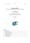
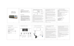
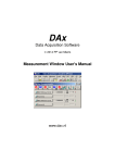
User’s Manual
STP3T10KE
STP3T15KE
STP3T20KE
STP3T30KE
CyberPower Systems Inc.
www.cpsww.com
Safety Precautions
This manual is about the installation and the operation of UPS (Here after referred as UPS).
Please read this manual carefully before move
、installation、operation and maintenance.
The UPS must be debugged and maintained by professional engineers of manufacturer or qualified
agents. Otherwise, human safety and UPS would be in danger; We do not take the responsibility if the
damage of UPS or human being was caused by users.
UPS is only for commercial / industrial use and not for life long equipment.
APPLICABLE STANDARDS
This product complies with CE 73/23 & 93/68 (low voltage safety) and 89/336 (EMC) , and EMC
standards of Australia and New Zealand (C-Tick) , and the following UPS product standards:
*IEC62040-1-1-General and safety requirements for use in operator access area
*IEC/EN62040-2 EMC requirements CLASS C3
*IEC62040-3 Performance requirements and test methods
Continued compliance requires installation in accordance with these instructions and the use of
manufacturer approved accessories only.
WARNING- High earth leakage current
The earth is critical. Before connect the input supply (include both commonercial power supply and
battery supply) . This equipment must be earthed in accordance to local electrical authority codes of
practice.
Earth leakage current exceeds 3.5 mA and is less than 1000 mA.
Transient and steady-state earth leakage currents, which may occur when starting the equipment,
should be taken into account when selecting instantaneous RCCB or RCD devices.
Residual Current Circuit Breakers ( RCCBs) must be selected insensitive to DC unidirectional pulses
( class A ) and transient current pulses ( RCCBs) .
Note it that the earth leakage currents of the load will also flow across RCCB or RCD.
Components can be maintained by users
All the equipment maintenance and servicing procedures involving internal access need special tools
and should be carried out only by trained personnel. The components that can only be accessed by
opening the protective cover with tools cannot be maintained by user.
This UPS full complies with “IEC62040-1-1-General and safety requirements for use in operator
access area UPS”.Dangerous voltages are present within the battery box. However, the risk of contact
with these high voltages is minimized for non-service personnel. Since the component with dangerous
voltage can only be touched by opening the protective cover with a tool, the possibility of touching high
voltage component is minimized. No risk exists to any personnel when operating the equipment in the
normal manner, following the recommended operating procedures in this manual.
Battery Voltage Higher Than 400Vdc
The battery maintenance and service procedures need internal access with special tools and keys
which should be carried out only by trained persons
Smart Tower UPS 10-30KVA User Manual
I
Safety Precautions
SPECIAL CARES SHOULD BE TAKEN WHEN WORKING WITH BATTERIES OR ASSOCIATED
EQUIPMENT. WHEN CONNECTED TOGETHER, THE BATTERY TERMINAL VOLTAGE WOULD
EXCEED 400Vdc ,AND IT IS POTENTIALLY LETHAL.
Battery manufacturers supply details of all necessary precautions of battery banks usage and in the
vicinity of the battery banks that should be taken all the time.Togther concern of the the local
environmental recommendations and the provision of protective clothing, first aid facilities, fire-fighting
facilities and firefighting rules
Battery life will be shorter as the enviroment temperature rise up.
Periodical batteries changes make UPS work normally. Ensure enough standby time
When replacing the batteries,using the same type and modal ,and the same quantity.
When batteies connected,the battery terminal voltage will exceed 400Vdc dangerous voltage, to avoid
electric shock accident, when replacing the batteries, please observe the following warning:
1 Wear eye shield, to prevent accidental arc injury eyes;
2 Don't wear a watch,a ring or any similar metal objects;
3 Use insulated tools;
4 Wear protective overalls and rubber gloves;
5 Do not put metal tools or similar metal parts on any battery;
6 Before remove battery connection terminals, disconnected the load on the battery;
7Do not exposed battery on fire,to invoid the explosion danger to humanbeing safety;
8 Do not Short the battery ,it will cause electric shock or fire;
9 If skin touch electrolyte, rinse with water immediately.
Recycle
UPS components containing heavy metals, must be treat as industrial waste after
be scrapped
II
Smart Tower UPS 10-30KVA User Manual
Contents
CONTENTS
Chapter 1 Quick Start ................................................................................................................................ 1
1.1 Introduction .................................................................................................................................... 1
1.2 Unpacking &Inspection .................................................................................................................. 1
1.3 Environment Inspection ................................................................................................................. 1
1.4 Installation Inspection .................................................................................................................... 1
Chapter 2 Installation Guidance ................................................................................................................ 2
2.1 Introduction .................................................................................................................................... 2
2.2 Position Selection .......................................................................................................................... 2
2.2.2 Battery Room .............................................................................................................................. 3
2.2.3 Storage ....................................................................................................................................... 3
2.3 Disassembly, Initial Checking and Positioning ............................................................................... 3
2.3.1 System Disassembly .................................................................................................................. 3
2.3.2 UPS Composition ....................................................................................................................... 4
2.3.3 Operation Space ......................................................................................................................... 4
2.3.4 Front Operation and Rear Operation .......................................................................................... 4
2.3.5 Final Position .............................................................................................................................. 4
2.3.6 Cable Entry ................................................................................................................................. 5
2.4 Protection Device........................................................................................................................... 5
2.4.1 Rectifier and Bypass Input .......................................................................................................... 5
2.4.2 Battery ........................................................................................................................................ 5
2.4.3 UPS Output................................................................................................................................. 6
2.5 Power Cables ................................................................................................................................ 6
2.5.1 Maximum stable state current and system cable configuration................................................... 6
2.5.2 Cable Connection ....................................................................................................................... 6
2.5.3 Connection of Battery (Only Applicable to Build-in Battery UPS model) ..................................... 7
2.6 Control and Communication Cable ................................................................................................ 8
2.6.1 Battery and Environmental Temperature Detection Dry Contacts (Optional) .............................. 9
2.6.2 Remote EPO Input Port (Optional) ............................................................................................. 9
2.6.3 Generator Input Dry Contact (Optional) .................................................................................... 10
2.6.4 BCB Interface (Optional) ........................................................................................................... 11
2.6.5 Battery voltage alarm Output Dry Contact Interface (Optional) ................................................. 11
2.6.6 Integrated alarm output dry contact Interface (Optional) ........................................................... 12
2.6.7 Mains/Commercial power failure alarm Output Dry Contact Interface (Optional)...................... 12
2.6.8 RS232 Port and SNMP Card Port............................................................................................. 13
2.7 Installation Diagram .................................................................................................................. 13
Chapter 3 Operation ................................................................................................................................ 15
3.1 Introduction .................................................................................................................................. 15
3.1.1 Work Principle........................................................................................................................... 15
3.1.2 Bypass Module principle ........................................................................................................... 15
3.1.3 Battery Temperature Compensation ......................................................................................... 16
3.2 Operation Mode ........................................................................................................................... 16
3.2.1 Normal Mode ............................................................................................................................ 16
3.2.2 Battery Mode ............................................................................................................................ 17
3.2.3 Auto-Start Mode ........................................................................................................................ 17
3.2.4 Bypass Mode ............................................................................................................................ 17
3.2.5 Maintenance Mode ................................................................................................................... 17
3.2.6 ECO Mode ................................................................................................................................ 17
3.2.7 Frequency Converters Mode .................................................................................................... 17
3.2.8 Parallel connection redundancy mode ...................................................................................... 17
3.3 Battery Management ................................................................................................................... 18
Smart Tower UPS 10-30KVA User Manual
III
Contents
3.3.1 General function ....................................................................................................................... 18
3.3.2 Advanced Functions (Battery Self-test Maintenance) ............................................................... 18
3.4 Battery Protection ........................................................................................................................ 18
Chapter 4 Installation of Parallel Operation System ................................................................................ 19
Chapter 5 Operating Procedures............................................................................................................. 20
5.1 Power Switches ........................................................................................................................... 20
5.2 UPS Start-up................................................................................................................................ 20
5.2.1 Normal Start Mode .................................................................................................................... 20
5.2.2 Battery Module Start Only Applicable for the UPS with Battery Cold Start Elements ....... 22
(
)
5.3 Procedures of Switch between Operation Modes ........................................................................ 22
5.3.1 Procedure of Switch the UPS into Battery from Normal Mode .................................................. 22
5.3.2 Procedure of Switch the UPS into Bypass from Normal Mode ................................................. 22
5.3.3 Procedure of Switch the UPS into Normal from Bypass Mode ................................................. 22
5.3.4 Procedure of Switch the UPS into a Maintenance Bypass from Normal Mode ......................... 23
5.3.5 Procedure of Switch the UPS to Normal from a Maintenance Bypass Mode ............................ 23
5.4 Procedure of Completely Power the UPS down .......................................................................... 23
5.5 EPO Procedure............................................................................................................................ 23
5.6 Language Selection ..................................................................................................................... 24
5.7 Password Control ........................................................................................................................ 24
Chapter 6 Operator Control and Display Panel ....................................................................................... 25
6.1 Introduction .................................................................................................................................. 25
6.1.1 LED Indicator ............................................................................................................................ 26
6.1.2 Audible Alarm (buzzer) ............................................................................................................. 26
6.1.3 Functional Keys ........................................................................................................................ 26
6.2 LCD Display Type ........................................................................................................................ 27
6.2.1 Default Screen .......................................................................................................................... 27
6.2.2 Data Screen .............................................................................................................................. 27
6.2.3 Setting Display screen .............................................................................................................. 28
6.2.4 Function screen ........................................................................................................................ 28
6.2.5 State Screen ............................................................................................................................. 28
6.2.6 Confirm screen ......................................................................................................................... 29
6.2.7 History Record Display ............................................................................................................. 29
6.3 Detailed Description of Menu Items ............................................................................................. 29
6.4 Alarm List ..................................................................................................................................... 30
Chapter 7 Maintenance ........................................................................................................................... 32
7.1 Instruction of Maintenance Operation .......................................................................................... 32
7.1.1 Precautions ............................................................................................................................... 32
7.1.2 Instruction to Bypass Module .................................................................................................... 32
Chapter 8 Product Specification .............................................................................................................. 33
8.1 Applicable Standards ................................................................................................................... 33
8.2 Environmental Characteristics ..................................................................................................... 33
8.3 Mechanical Characteristics .......................................................................................................... 33
8.4 Electrical Characteristics (Input Rectifier) .................................................................................... 34
8.5 Electrical Characteristics (Intermediate DC Link)......................................................................... 34
8.6 Electrical Characteristics (Inverter Output) .................................................................................. 34
8.7 Electrical Characteristics(Bypass Mains Input) ............................................................................ 35
8.8 Efficiency ..................................................................................................................................... 36
IV
Smart Tower UPS 10-30KVA User Manual
Chapter 1 Quick Start
Chapter 1 Quick Start
1.1 Introduction
This chapter describes the basic principles of UPS installation and commission; it helps users to
achieve a rapid installation and commissioning
1.2 Unpacking &Inspection
Check the following items after receiving the products.
1.
Check that the package is intact. If there is any damage or humidification, please contact the local
agents or offices.
2.
Check the outer type designation label in consistence with the booked product. If not, please contact
the local agents or offices.
3.
Check if there is no water inside the package and any damage or crack to the shell. If not, please
contact the local agents or offices.
4.
Check that the nameplate is the same as the outer type designation label. If not, please contact the
local agents or offices.
5.
Check whether the internal accessories are complete. If not, please contact the local agents or
offices.
1.3 Environment Inspection
Confirm the items as following before UPS installation.
℃
1.
Check the environment temperature, if above 25 ,please add cool system.
2.
If the operation environment temperature is below 0
3.
If the UPS operation environment humidity is above 90% or condensation, please add additional
protection.
4.
Whether there is sunshine or external species invasion in the UPS operation environment, please
add additional protection.
5.
If there is dust, inflammable and explosive gas in UPS operation environment, please add additional
protection.
℃, battery life reduces half every each 10℃ up.
℃ or not, add heat equipment if yes..
Note: Environment temperature above 20
1.4 Installation Inspection
After installation, check the items as below:
1.
If the UPS is installed on inflame retarding material?
2.
All the cables connected correctly
3.
All the grounded system connected correctly.
4.
If the operation space around UPS enough.
5.
Confirm all the UPS external terminals are tight, and the torque should meet the requirements.
6.
Confirm that there are no screws, cables and other electric conductor left inside the UPS. If there is,
please take out.
Smart Tower UPS 10-30KVA User Manual
1
Chapter 2 Installation Guidance
Chapter 2 Installation Guidance
2.1 Introduction
This chapter introduces UPS installation, as particularity of every installation condition. This chapter
just provides guidance of the general installation procedures and methods. Please installation engineers
operate according to difference for each place,
Warning-Installation can only be done by authorized engineers
1. Do not apply electrical power to the UPS equipment before the approval of commissioning
engineer.
2. The UPS should be installed by a qualified engineer in accordance with the information contained in
this chapter.
Note: 3-Phase 4-Wire Input Power is required
The standard UPS can be connected to TN, TT and IT AC distribution system (IEC60364-3) of
3-phase 5-wire
WARNING: battery hazards
SPECIAL CARE SHOULD BE TAKEN WHEN WORKING WITH THE BATTERIES ASSOCIATED
WITH THIS EQUIPMENT. When connecting the battery, the battery terminal voltage will exceed
400Vdc and is potentially lethal.
Eye protection should be worn to prevent injury from accidental electrical arcs.
Remove rings, watches and all metal objects.
Only use tools with insulated handles.
Wear rubber gloves.
If a battery leaks electrolyte, or is otherwise physically damaged, it must be replaced, stored in a
container resistant to sulfuric acid and disposed of in accordance with local regulations.
If electrolyte comes into contact with the skin, the affected area should be washed immediately
with water.
2.2 Position Selection
2.2.1 Power Distribution Room
The UPS is designed for indoor installation, and it should be located in a clean environment with
adequate ventilation to keep the environmental temperature within the required specification parameter.
The UPS internal fans provide forced draft cooling, cold air flow through the front grille into the internal of
UPS, and exhaust hot air from the back grille. Do not block ventilation hole.
If necessary, install some indoor exhaust fans to avoid temperature increase.
In dusty environment, it is better to install air filter, optional component of UPS
Note: The UPS should be installed only on concrete surface or other surface that is solid and
not combustible.
2
Smart Tower UPS 10-30KVA User Manual
Chapter 2 Installation Guidance
2.2.2 Battery Room
The batteries will generate a small amount of hydrogen and oxygen at the end of charging, so keep
the batteries installation environment adequate fresh air ventilation must meet EN50272-2001
requirements.
The ambient temperature of the batteries should be stable. Environment temperature is the main
factor influent batteries capacity and life.
The batteries standard operation temperature is 20°C. Above this temperature, it will reduce the
battery life, and below this temperature it will reduce the battery capacity.
If the average operation temperature of battery is increased from 20ºC to 30ºC, then the life of the
battery will be reduced by 50%. If the operating temperature of the battery is above 40ºC, then the battery
life will be decreased in exponent rate.
In normal situation, the battery allowing temperature should be at 15°C to 25°C. Keep batteries far
away from heat and air vents.
UPS use external batteries, and the battery protection device (a DC circuit breaker) must be
mounted close to batteries as possible. Between it with batteries, use the shortest power cables
connection distance.
2.2.3 Storage
If there is no need to install the UPS immediately, must be kept the UPS inside a room so as to
protect it against too wet or too hot environment.
The battery needs to be stored in a dry and cool place with good ventilation. The most appropriate
storage temperature is 20 ºC ~ 25ºC.
2.3 Disassembly, Initial Checking and Positioning
When the product is delivered to the user after the first inspection, packaging, determine the intact;
and then open the package, check the equipment integrity; if damaged, please immediately notify the
carrier.
2.3.1 System Disassembly
Open the wooden case first, and then take out the foam pay attention not to scratch the UPS
Fig 2-1 UPS Packing Diagram
Tip: After disassembly, as shown in Figure 2-1, remove the bolts that connect to the UPS
cabinet and wooden Cashion, then lift the UPS cabinet to the installation position. The
dismantlement should be careful so as not to scratch the UPS.
Smart Tower UPS 10-30KVA User Manual
3
Chapter 2 Installation Guidance
After the carton opening, verify the product label and confirm the correctness of the equipment. The
equipment label is attached on the back and front door which show the UPS model, capacity and main
parameters.
Warm Tips: Please dispose the wasted material in accordance to
environmental protection requirements after disassembly.
To prolong the service life, the UPS location shall be selected to ensure:
convenient wiring
Sufficient space for operation
good ventilation , enough for UPS heat dissipation
No ambient corrosive gases
Not damp and no heat sources
Not dusty
Meet the fire protection requirements
The operating environment temperature is 20 -25 ,the batteries maximum efficiency temperature
range (for the information about the battery storage and transportation as well as the environment,
please refer to table 7-2)
℃ ℃
2.3.2 UPS Composition
UPS compositions refer to fig 2-2.
a. 10KVA~30KVA cabinet without built-in battery
b.10KVA~30KVAcabinet with built-in battery
Fig 2-2 UPS Component Diagram
2.3.3 Operation Space
As UPS has no ventilation grills at either side, no clearance is required for the sides.
For the convenience of daily operation tightening the power supply terminals in the UPS cabinet, with
the exception meet the local requirements, enough space also should be retained for the cabinet front
and back doors. When the front doors are fully opened, a person can pass through freely. Keep the UPS
cabinet back door distance away from the wall or other cabinet for maintenance more than 800mm.
2.3.4 Front Operation and Rear Operation
The UPS device layout makes the maintenance, diagnosis and repair of the cabinet completely at the
front and rear, thus reducing the side space requirements
2.3.5 Final Position
After UPS has been finally located, ensure the expansion bolts fixing the UPS reliably.
4
Smart Tower UPS 10-30KVA User Manual
Chapter 2 Installation Guidance
2.3.6 Cable Entry
10KVA~30KVA UPS adopts underneath power cable routing.
2.4 Protection Device
For safety, it is recommended to install external circuit breakers or other protective devices in the AC
supply system of the UPS system. This section provides general guidance to the trained and qualified
professionals. Training and qualified professionals should be aware of the equipment to be installed local
wiring regulations and relative knowledge
2.4.1 Rectifier and Bypass Input
Install appropriate over current protective devices in the distribution unit of the commercial power
supply, the installation should be considered the power cable current capacity and the system overload
capacity. It is recommended for general that use specified in table 2-2 current 125% IEC60947-2 tripping
curve C (normal) thermal magnetic circuit breaker.
Note
For IT power system,4-pole protective device must be installed in power input distribution cabinet external of UPS
If install UPS higher input power distribution leakage detecting instrument, the adopted residual
current action protector (RCD) must:
Sensitive to DC unidirectional pulses (class A) in the power network
Insensitive to transient current pulses
Normal sensitivity, adjustable in 0.3A ~ 1A
The Residual Current Circuit Breaker (RCCB) must be sensitive to DC unidirectional pulses (class A)
in the network, insensitive to transient current pulses, as shown in fig 2-3 respectively.
Fig 2-3 RCCB sign
2.4.2 Battery
A battery bank contains 40 series batteries, Intermediate (the joint of the 20th and 21st batteries),
elicits a midline, plus the first, the last totally 3 cables connect to UPS terminals. Battery elicited cables
must go through a DC circuit breaker then connect to the relevant UPS terminal rows showing in fig 2-4
as below:
Forty series batteries connection
Fig 2-4 Diagram of series batteries connection
Smart Tower UPS 10-30KVA User Manual
5
Chapter 2 Installation Guidance
2.4.3 UPS Output
There UPS main output switch was built in; users should install overcurrent protector for each output
branch in the additional distribution cabinet.
2.5 Power Cables
Design the cables according to the descriptions of this section and local regulation of wiring
standards, and consider the environmental conditions. Refer to IEC60950-1 table 3B.
Warning
Prior to the cables connection, confirm be aware of the UPS input and the commercial power switch
positions and states.
Ensure switches are opened, and attach a WARNING label to prevent others to operate the switch.
2.5.1 Maximum stable state current and system cable configuration
Table 2-1 Maximum stable state current and configuration of cable system
System Name
Capacity
System capacity
Cabinet
dimension mm
W*D*H
Main Input
Output
Battery
PE
STP3T10KE
STP3T15KE
STP3T20KE
STP3T30KE
10KVA
15KVA
20KVA
30KVA
540*690*1100
(with built-in battery)
280*730*668 (without built-in battery)
320* 781* 788
Rated current A
15
22.5
30
45
Cable mm2
4
6
10
10
Rated current A
15
22.5
30
45
Cable mm2
4
6
10
10
Rated current A
18
26.5
36
53
Cable mm2
6
10
10
16
Cable mm2
10
10
16
25
Terminal location shows as Figure 2-13
Warning
FAILURE TO FOLLOW ADEQUATE EARTHING CAN RESULT IN ELECTROMAGNETIC
INTERFERENCE ( EMI), ELECTRIC SHOCK HAZARD AND FIRE HAZARD
2.5.2 Cable Connection
Important
The operations described in this section must be performed by trained and qualified professionals. If
you have any doubt, please contact with manufacturer local Customer Service & Support department.
After the equipment finally positioned, please refer to the installation diagram following the
procedures as following:
1.
Ensure all the input distribution switched off, and disconnect all the UPS internal power, Attach
warning labels on these switches to prevent others to operate.
2.
Open the UPS cabinet front door, and remove the cover plate, then the input and output terminals,
battery terminals and earth terminal are visible.
6
Smart Tower UPS 10-30KVA User Manual
Chapter 2 Installation Guidance
3.
Connect the input earth wire to input earth terminal. Note: the earth wire connection should comply
with the local and national regulations
4.
When the input of UPS rectifier and bypass adopt a same power supply, AC input cables should be
connected to the UPS input terminal (Main input A-B-C-N), the output load cables should be
connected to the UPS output terminal (Output A-B-C-N). When there are two ways electric
supply inputs, connect the power cable for UPS rectifier and bypass respectively, main input
terminal of UPS (Main input A-B-C-N) and the input terminal of the bypass, and at the same
time remove the short circuit copper bars of the main and the bypass; For the cable tight,
the required force moment including 30kg (M5), 50kg (M6), 180kg (M8) and 260kg (M10).
Attention ensures the power cable phase sequence consistent and there is no circuit short at any
joint of cable terminals.
5.
Connect the battery cables between the UPS battery terminals and the battery switch. ENSURE
battery cable CORRECT polarity connection.
Warning-Hazardous battery terminal voltage exceed of 400Vdc
Ensure the connection from battery terminals to battery Circuit breack and to UPS terminals polarity
consistance: Positive terminal to positive terminal, negative terminal to negative terminal, and
disconnect one or more than one cables every battery layer.Do not connect the cables and the battery
circuit breakers without approval from the trained and qualifiied commissioning engineer.
6.
Re-install all the protective cover plates
2.5.3 Connection of Battery (Only Applicable to Build-in Battery UPS model)
The below 30KVA UPS contain battery build-in model, in which there is an internal battery breaker.
At the same time, the UPS also offers external battery connection terminals. When choosing external
battery, it should be added an extra battery breaker between the UPS and the external battery bank
Users can choose below 30KVA UPS with or without build in batteries (40*12AH), Customer can
install the battery and connect the battery cables according to the actual situation. We also provide the
battery cables as an option for customers to choose. The method of build-in batteries connection shown
as following fig. 2-5:
Smart Tower UPS 10-30KVA User Manual
7
Chapter 2 Installation Guidance
Fig 2-5a Build-in battery connection diagram
The UPS and batteries are connected by Anderson terminals as shown below, according to the mark
of cables, connect cables W404,W405,W406 to K(+),K(N),K(-).
Fig 2-5b Build-in battery connection diagram
2.6 Control and Communication Cable
As shown in fig. 2-6, there are dry contact interfaces (J2-J10), communication interfaces (RS232
interface, 485 interface, and SNMP card interface) and LBS interface.
8
Smart Tower UPS 10-30KVA User Manual
Chapter 2 Installation Guidance
Fig 2-6 Dry contact interface and communication interface
There is optional dry contact board, the UPS receives external signal from zero-voltage (dry contacts)
contact signal to bypass module phoenix terminals. Via software program operation, it the signal will be
valid when these contacts shorted with +24V pins. All the control cables must be dual isolated, and they
should be separated to the power cables, within maximum wiring distance 20m~50m,the control cable
2
section area should be 0.5 to 1.5 mm .
2.6.1 Battery and Environmental Temperature Detection Dry Contacts (Optional)
Input dry contact J2 and J3 can detect the battery and environment temperatures, which can be used
for environment monitoring and battery temperature compensation.
J2 and J3 interfaces diagram is shown in fig 2-7, interface description refer to table 2-2.
J2
J3
Fig 2-7 Temperature dry contacts J2 and J3
Table 2-2 Description of input dry contact J2 and J3
Position
Name
Description
J2.1
J2.2
J3.1
J3.2
TEMP_BAT
GND
TEMP_ENV
GND
Battery temperature detection
Power ground
Environment temperature detection
Power ground
Note:
Temperature detection requires specified temperature sensor(R25=5KOhm, B25/50=3275), please
confirm with manufacturer, or contact manufacturer local office when ordering.
2.6.2 Remote EPO Input Port (Optional)
The UPS has an Emergency Power OFF (EPO) function which can be activated by pressing the EPO
button on the UPS control panel or through a remote-contact provided by user. The EPO button is
protected by a hinged plastic cover.
J4 is the input port of remote EPO, it does work when NC and +24v are shorted, When the EPO
requires to be triggered, disconnected NC and +24v, or shorted NO and +24v. The port diagram is shown
in Fig 2-8, the port description is shown in table 2-3.
Smart Tower UPS 10-30KVA User Manual
9
Chapter 2 Installation Guidance
+24V
J4
Fig 2-8 remote EPO input port Diagram
Table 2-3 Description of remote EPO input port
Position
Name
Description
J4.1
EPO_NC
EPO is activated when disconnecting fromJ4.2
J4.2
+24V
+24V, connect the common terminal of NC and NO
J4.3
EPO_NO
EPO is activated when shorting with J4.2
The EPO is triggered by shorting pin 2 and 3 or opening pin 2 and 1 of J4.
If the external emergency stop function is required, J10 is reserved for. The external emergency stop
needs extra shielded cable connect the NO or NC remote switch to the J10 port; if the function is not in
use disconnect the pin 2 and pin 3,and short the pin1and pin2 of J4
Note
1. The UPS emergency stop action will shut down rectifier, inverter and static bypass. However, it
does not internally disconnect the input main power. For the UPS full power down, Disconnect the
upper input switch when trigger the EPO.
2. Pin 1 and 2 of J4 have been shorted before leaving factory
2.6.3 Generator Input Dry Contact (Optional)
J5 is the generator input status interface. Connecting pin 2 of J5 with + 24V power supply, indicates
the generator is connected to the system. The interface diagram is shown in fig 2-9 and interface
description is shown in table 2-4
Generator
Fig 2-9 Generator access interfaces and connections Diagram
10
Smart Tower UPS 10-30KVA User Manual
Chapter 2 Installation Guidance
Table 2-4 Maintenance bypass switch and output switch status interface Description
Position
Name
J5.1
J5.2
J5.3
+24V
GEN
GND
Description
+24V power supply
Connection status of generator
Power ground
2.6.4 BCB Interface (Optional)
BCB_ONL
BCB_CON
T
BCB_DRV
J6 and J7 are battery circuit breaker (BCB) interface. The interface diagram is shown in fig 2-10 and
the interface description is shown in table 2-5.
Fig 2-10 BCB Interface
Table 2-5 Description of BCB Interface
Location
J6.1
Name
BCB_DRV
J6.2
BCB_CONT
J7.1
GND
J7.2
BCB_ONL
Description
BCB drive signal: providing +24V, 20mA drive signal
,
BCB contact status connect to BCB’s normal open signal
Power ground
(
BCB online input normal open
),it shows BCB is online when this
signal connects to GND.
2.6.5 Battery voltage alarm Output Dry Contact Interface (Optional)
GND
BAT_LOW_NO
BAT_LOW_NC
J8 is an output dry contact interface that outputs battery alarms. When the voltage is lower than set
value, it will provide an auxiliary dry contact signal via the isolation of a relay. The interface diagram is
shown in fig 2-11, and description is shown in table 2-6.
Fig 2-11 Integrated Battery alarm dry contact interface diagram
Table 2-6 Integrated Battery alarm dry contact interface description
Smart Tower UPS 10-30KVA User Manual
11
Chapter 2 Installation Guidance
Location
Name
J8.1
J8.2
J8.3
BAT_LOW_NC
BAT_LOW_NO
GND
Description
Battery warning relay (normally closed) will be open during warning
Battery warning relay (normally open) will be closed during warning
Center of battery warning relay
2.6.6 Integrated alarm output dry contact Interface (Optional)
J9 is a integrated alarm output dry contact interface, when one or more alarms is/are triggered, the
system will send a integrated alarm information, it provides an auxiliary dry contact signal via the isolation
of a relay. The interface diagram is shown in fig 2-12, and description is shown in table 2-7
GND
ALARM_NO
ALARM_NC
J9
Fig 2-12 Integrated alarm dry contact interface diagram
Table 2-7: Integrated alarm dry contact interface description
Location
J9.1
J9.2
J9.3
Name
Description
ALARM_NC Integrated warning relay (normally closed) will be open during warning
ALARM_NO Integrated warning relay (normally open) will be closed during warning
GND
Centre of integrated warning relay
2.6.7 Mains/Commercial power failure alarm Output Dry Contact Interface (Optional)
J10 is a output dry contact interface for mains power failure alarm, when the mains fails, the system
will send a mains failure alarm, to provide an auxiliary dry contact signal via an isolation relay. The
interface diagram is shown in fig 2-13, and the description is shown in table 2-8.
Fig 2-13 Mains failure warning dry contact interface diagram
Table 2-8 Mains failure warning dry contact interface description
Location
J10.1
12
Name
Description
UTI_FAIL_NC Mains failure warning relay(normally closed) will be open during warning
Smart Tower UPS 10-30KVA User Manual
Chapter 2 Installation Guidance
Location
J10.2
J10.3
Name
Description
UTI_FAIL_NO Mains failure warning relay( normally open) will be closed during warning
GND
Centre of mains failure warning relay
2.6.8 RS232 Port and SNMP Card Port
RS232 and RS485 Ports: provide serial data for authorized maintenance or commissioning
engineers, and also can be used for integrated network monitoring system.
SNMP Card Port: be used for field installation the communication option card (SNMP card).
2.7 Installation Diagram
Smart Tower UPS 10-30KVA User Manual
13
Chapter 2 Installation Guidance
a. 10KVA~30KVA wiring diagram (with built-in battery)
b. 10KVA~30KVA wiring diagram (without built-in battery)
Fig 2-13 10~30KVA UPS wiring diagram
14
Smart Tower UPS 10-30KVA User Manual
Chapter 3 Operation
Chapter 3 Operation
This chapter introduces basic knowledge of UPS operation, including working principle, operation
mode, battery management and protection.
Warning: Hazardous mains voltage and/or battery voltage present(s) behind the
protective cover
1
.The components that can only be accessed by opening the protective cover with tools cannot be
operated by user.
2 Only qualified trained professinals are authorized to remove such protective covers.
.
3.1 Introduction
UPS provides high quality uninterruptible AC power to your critical load. The UPS output power voltage
and requency do not be affected by mains input low voltage, power off, peaks and so on.
The UPS adopts the latest high-frequency double-conversion pulse width modulation (PWM)
technology and fully digital control (DSP) technology, high reliability, convenient for use..
3.1.1 Work Principle
As shown in fig 3-1, the AC input from mains transformer to DC Power in rectifier. The inverter
transformer this DC power which is coming form battery set(s) or the rectifier transformed power as AC
power ,and supply load through the distribution modules. When the commercial power is off, the battery
set(s) supply back-up power for the load through the inverter; it also can utility the mains through the static
bypass to load.
When the UPS needs maintenance or repairing, transfer the load to maintenance bypass, the power
supply would be uninterrupted.
Fig 3-1 System principle framework diagram
3.1.2 Bypass Module principle
Fig 3-1 shows the “bypass module” contains electronic controlled switch circuits that allow the load
connected to the inverter output or through the static bypass line to bypass power supply. IN normal
condition, inverter supply power for load; if overload or inverter failure, the load will be switched to static
bypass power supply.
Smart Tower UPS 10-30KVA User Manual
15
Chapter 3 Operation
Under normal operation condition, the inverter output and static bypass power supply must be fully
synchronized to achieve uninterrupted load switch between inverter output and static bypass line, The
synchronization of the inverter output and static bypass power is achieved by the inverter control circuit,
When the static bypass power frequency is in a allowed value for synchronization, the inverter control circuit
always keep the inverter output frequency tracking the static bypass power frequency.
UPS support a manually controlled maintenance bypass. When UPS shut-down for maintenance or
repair. It enables the critical load to be powered from this bypass power supply
Note
When the UPS is running in bypass mode or supporting power for load on maintenance bypass, there
is no abnormal ac power protection for load equipment.
3.1.3 Battery Temperature Compensation
Connect the temperature sensor to UPS battery temperature interface in battery cabinet to achieve
optimized battery management.
Fig 3-2 Temperature compensation diagram
3.2 Operation Mode
The UPS are on-line, double-conversion, reverse-transfer UPS, and they have the following operation
modes:
Normal mode
Battery mode
Auto-Restart mode
Bypass mode
Maintenance mode (manual bypass)
ECO mode
Frequency converters mode
Parallel operation redundancy mode
3.2.1 Normal Mode
Mains supplying power to UPS rectifiers provide DC to inverters, which provide continuously
uninterrupted AC power to the load. The rectifier provides battery floating charge or boost charge via
charger simultaneously.
16
Smart Tower UPS 10-30KVA User Manual
Chapter 3 Operation
3.2.2 Battery Mode
Batteries provide back-up power to load through inverter mode is battery mode. The UPS automatically
switch to battery mode, and load power is not interrupted. After the mains returns, the UPS automatically
switches back to normal mode without any manual intervention, while the load power uninterrupted.
Note: UPS can also be started through battery (charged) mode via battery cold start function when the
mains failure. Therefore, the battery power can be used independently to improve the utilization rate of
UPS.
3.2.3 Auto-Start Mode
The UPS has auto boot function, and that is after a long time mains failure, the inverter shut down
when the battery reaches the End of Discharge voltage (EOD). The UPS may be programmed to “Auto
Recovery after EOD” after a delay time if the AC main returns. This mode and any delay time are
programmed by the qualified professionals
During the automatically delay boot process, the UPS will charge the batteries to prevent another
mains failure risks for load equipment in future.
3.2.4 Bypass Mode
In normal mode, if there is inverter failure, inverter overload or manually turn off the inverter, static
switch will switch to bypass power supply the load power will not be interrupted
3.2.5 Maintenance Mode
For UPS maintenance or repair, switch load through the manual switch the critical load power supply
will no be off.
Be aware that switch the UPS system to bypass power supply mode first, then remove the
anti-manipulation cover, rotate the handle to maintenance, then disconnect all the mains, bypass and
internal battery switches and the external battery cabinet switches.
Warning: Hazard wrong operation in maintenance bypass mode
After UPS transfered to operate in maintenance bypass mode, power modules and bypass modules
do not work ,there is no display on LCD, the input,output terminalsand the N bus are energized with
electricity.
3.2.6 ECO Mode
When choosing economical (ECO) mode, in most situations, the UPS double-conversion would be
forbidden for energy saving. In ECO mode, the load power supply priority provided by the bypass. When the
frequency and voltage of bypass power within normal range, load power provided by bypass; beyond this
range, the system will switch to output of inverter, but such would cause load power interruptions, the
interruption time is less than 3/4 cycle. For example, the frequency is 50Hz, the interruption time is less than
15ms; frequency is 60Hz, the interrupt time of less than 12.5ms.
3.2.7 Frequency Converters Mode
UPS can be set as frequency converter mode, and it provides stable frequency output as 50Hz or 60Hz,
the input frequency range is 40Hz ~ 70Hz. In this mode, the static bypass is unavailable, and the battery
can be selected according to the actual requirements of battery mode.
3.2.8 Parallel connection redundancy mode
To increase the system capacity or reliability, or both increase the system capacity and reliability, we
could paralleled some number of UPS units directly, and each UPS will automatic load-sharing by its
internal parallel logic control. The capacity of a parallel operation system can be up to 6 units.
Smart Tower UPS 10-30KVA User Manual
17
Chapter 3 Operation
3.3 Battery Management
3.3.1 General function
The following functions should be performed by trained and qualified professionals with specified
software.
1.
Constant current boost charging
The charge current can be set.
2.
Constant voltage boost charging
Set the charge voltage according to battery type.
For Valve Regulated Lead Acid (VRLA) batteries, the maximum boost charge voltage should not
exceed 2.4V/cell
3.
Float charge
The float charge Voltage can be set as required by the type of battery.
For Valve Regulated Lead Acid (VRLA), float charge voltage should be between 2.2V and 2.3V.
4.
Float charge temperature compensation (optional)
The temperature compensation coefficients can be set depending on battery type.
5.
End of discharge (EOD) protection
When the battery voltage falls below the EOD, the battery converter will automatically be off,
disconnect the battery to avoid excessive battery discharge. EOD is adjustable from 1.6V to 1.75V per cell
(VRLA) or 0.9 to 1.1 V per nickel-cadmium (Ni-Cd) cell.
6.
Battery low voltage alarm time
Setting range, prior to the battery discharge termination 3 to 60 minutes, the default is 5 minutes.
3.3.2 Advanced Functions (Battery Self-test Maintenance)
Battery periodic discharge, and each time discharge 30% capacity. The actual load must exceed 30%
of the UPS nominal capacity. If the load is below 30%, it does not perform automatic discharge
maintenance. The periodic interval can be set from every 30 to 360 days. The battery self-test can be
disabled.
Conditions—batteries have been float charged for at least 5 hours, remain more than 30% of their rated
capacity, the load within 20~100% of UPS rated capacity
Be triggered—manually operate the command “Battery Maintenance Test” on LCD panel
3.4 Battery Protection
The following functions should be performed by trained and qualified professionals with specified
software.
1.
Battery Low voltage alarm
The battery under-voltage pre-warning occurs before the end of discharge. After this pre-warning, the
battery should have the capacity for 3 remaining minutes discharging with full load. The time is user
configured from 3 to 60 minutes.
2.
End of discharge (EOD) protection
Before the battery voltage falls below the EOD, the battery converter will automatically be off,
disconnect the battery to avoid excessive battery discharge. EOD is adjustable from 1.6V to 1.75V per cell
(VRLA) or 0.9 to 1.1 V per nickel-cadmium (Ni-Cd) cell.
3.
Battery Circuit Breaker (BCB) Alarm (Optional)
The BCB disconnecting occur this alarm. The batteries connect to UPS through the external battery
circuit breaker (BCB). BCB is closed manually, the switch trips when there is battery over-temperature or
electricity leakage by the UPS control circuit controlling.
18
Smart Tower UPS 10-30KVA User Manual
Chapter 4 Installation of Parallel Operation System
Chapter 4 Installation of Parallel Operation System
The parallel operation system installation is of same procedures of the installation the single system
requirement and this chapter.
The single devices should be located parallel and be connected as shown in fig. 4-1, the difference is
that the lengths of the output cables of the single devices is not more than 10m. It is recommended to use
an external bypass cabinet to facilitate maintenance and system testing.
Other power supplies
Mains power input,
L1, L2, L3, N terminals
Mains power input,
L1, L2, L3, N terminals
Rectifier
Charger
Inverter
Rectifier
Charger
Inverter
Output power supply
Load connected
Fig. 4-1 Typical 1+N parallel operation system
Note: when the load exceeds the capacity of a single device, the maintenance bypass switch
CB3 must be removed.
The parallel operation need double insulation shielded cable up to 30m long, the control cables for
the parallel operation must be connected all the single devices to form a closed loop, as shown in fig.4-2.
Fig.4-2 parallel cables
Smart Tower UPS 10-30KVA User Manual
19
Chapter 5 Operating Procedures
Chapter 5 Operating Procedures
This chapter describes UPS operation instructions in detail.
All functional buttons and LED display involve in operation instructions. Please refer to chapter 5.
During operation, the buzzer alarm may occur at any time. Select “mute” on LCD to muffle the audible
alarm.
Warning-Hazardous mains voltage and/or battery voltage present(s) behind the
protective cover
1. The components that can only be accessed by opening the protective cover with tools. It cannot be
operated by users.
2. Only qualified service professionals are authorized to remove such covers.
5.1 Power Switches
As shown in fig 5-1, open the front door of UPS, the power switch is visible, it includes: input switch,
output switch and maintenance bypass switch (with anti-misoperation stop plate)
a. 10KVA~30KVA (without built-in batteries)
Fig. 5-1
b. 10KVA~30KVA (with built-in batteries)
Main switch location diagram
5.2 UPS Start-up
The UPS system only has a maintenance bypass isolated switch, and all the other transfers are
processed automatically by internal control logics.
5.2.1 Normal Start Mode
This procedure must be followed when turn on the UPS from a fully power down system condition.
The operating procedures are as follows:
Warning
This procedure results in mains voltage being applied to the UPS output terminals. If any load
equipment is connected to the UPS output terminals please check with the user load that it is safe to
be supplied power. If the load is not ready to receive power then ensure that the output switch of
external distribution cabinet is off.
20
Smart Tower UPS 10-30KVA User Manual
Chapter 5 Operating Procedurce
Warning
Please confirm that UPS output rotating switch point to UPS, with anti-misoperation stop plate for
rotating switch is fixed well.
1. Close UPS bypass input switch and input switch in turns
The LCD starts up at this time. The Rectifier indicator flashes during the rectifier startup. The rectifier
enters normal operation state, and after about 30s, the rectifier indicator goes steady green. After
initialization, the bypass static switch closes. The UPS Analogue LEDs indicate as shown in table 5-1:
Table 5-1 Indicator status
LED
Status
Rectifier indicator
Battery indicator
Bypass indicator
Inverter indicator
Load indicator
Status indicator
Green
Red
Green
Off
Green
Green
Warning
The bypass input circuit breaker must be switched on first, then the input circuit breaker, otherwise,
the rectifier could not be started and the power would be out of the system’s control.
During the inverter starts up time, the inverter indicator flashes. After the rectifier enters normal
operation state, UPS power supply will transfer from bypass to inverter, then the bypass indicator turns off,
and load indicator lights on. The status of indicators is shown in table 5-2
Table 5-2 Indicators Status
LED
Status
Rectifier indicator
Green
Battery indicator
Red
Bypass indicator
Off
Inverter indicator
Green
Load indicator
Green
Status indicator
Green
If UPS belongs to build-in battery type, please close the internal battery DC switch. Battery indicator
will be off a few minutes later, the battery will be charged by UPS which is running in normal operation
mode. The indicator status is shown in table 5-3.
If your UPS is without build-in battery type, please close the external battery DC switch.
Warning
Please confirm battery connection correct before closing external battery switch.
Table 5-3 Indicator status
LED
Status
Rectifier indicator
Battery indicator
Bypass indicator
Inverter indicator
Load indicator
Load indicator
Green
Green
Off
Green
Green
Green
Smart Tower UPS 10-30KVA User Manual
21
Chapter 5 Operating Procedures
5.2.2 Battery Module Start
)
(Only Applicable for the UPS with Battery Cold Start
Elements
1. Check if the batteries have been connected, and close the internal/external battery switch.
2. Press the red start-up button of battery on the back door panel.
3. The LCD starts up at this time, press battery cold start again for about 5 seconds. The green battery
indicator flashes. The rectifier enters normal operation states and after about 30s, the battery indicator
goes steady green.
4. The inverter starts up automatically, the green inverter indicator flashes. The inverter will output after
60s. Then UPS runs in battery mode.
a. 10KVA~30KVA (without built-in battery)
b. 10KVA~30KVA (with built-in battery)
Fig. 5-2 Diagram of battery starting button location
5.3 Procedures of Switch between Operation Modes
5.3.1 Procedure of Switch the UPS into Battery from Normal Mode
Switch off Mains input, UPS enters battery mode. If need to switch UPS to normal mode, wait for a
few seconds before turn on the input switch. As to supply the mains again 10s later, the rectifier will start
up automatically to supply power to the inverter.
5.3.2 Procedure of Switch the UPS into Bypass from Normal Mode
Select the manual bypass menu of "function 1” of “function/ setting”
Note
In bypass mode, the load is directly supplied by the mains power instead of the AC power from the
inverter.
5.3.3 Procedure of Switch the UPS into Normal from Bypass Mode
Select Esc Byp (exit bypass mode) on the LCD, about 3 seconds later, UPS transfer to inverter
mode automatically.
22
Smart Tower UPS 10-30KVA User Manual
Chapter 5 Operating Procedurce
5.3.4 Procedure of Switch the UPS into a Maintenance Bypass from Normal Mode
In normal operation, this operation instruction will switch the load from inverted input to maintenance
bypass.
Caution
Before this operation, read messages on LCD to be sure that bypass supply is regular and
synchronize to the inverte so as not to risk a short interruption in powering the load.
1. Switch UPS from normal mode to bypass mode according to 5.3.2.
The inverter indicator and status indicator go off, the buzzer alarms. The load will be transferred to
static bypass, and the inverter close.
2. Remove anti-misoperation stop plate for rotary circuit breaker, then the rotary circuit breaker is
switched to the maintenance bypass side in order that the load power is supplied by the maintenance
bypass, and the mains switch Q1, the bypass switch Q2, the output switch Q4 and the internal and
external battery switches are disconnected.
Warning
If required to maintain the modules, the cabinet need to be opened for internal maitenance after 10
minutes waiting for the automatically discharging of capacitor in the internal DC bus.
5.3.5 Procedure of Switch the UPS to Normal from a Maintenance Bypass Mode
This procedure can transfer the load to normal mains mode when the UPS is running under the
maintenance bypass mode.
1
.Close the bypass switch Q2 ,and switch the rotary switch to “UPS output”
after 10 seconds.
The indicator light of the bypass become green and the power is supplied for the load by the
bypass.
2
.Close the mains input circuit breaker Q1
The power is supplied for the load by the bypass. At the same time, the rectifier begins to operate,
the indicator light of the rectifier become green after 30 seconds, and the power is automatically
supplied with the inverter after 2 minutes.
3. Close internal and external battery switches. If the indicator light of the battery does not work, the
voltage of the LCD display battery is inspected.
4. Replace the anti-misoperation stop plate for rotary switch.
5.4 Procedure of Completely Power the UPS down
When need power down the UPS completely, follow the procedures in section 5.3.4 to transfer the
UPS from normal mode to maintenance bypass mode.
If you need to isolate the UPS from the AC power supply, you should off the external input switch.
5.5 EPO Procedure
The EPO button on the UPS operates displaying and control panel that is designed to switch off the
UPS in emergency conditions (e.g., fire, flood, etc.).To achieve it, just press the EPO button, and the
system will turn off the rectifier, inverter and terminate the load power supply immediately (including the
inverter and bypass output), and the batteries stop charging or discharging.
If there is power input, the UPS control circuit would remain active; however, the output would be
turned off. To completely isolate the UPS, you need to disconnect the external mains input supply of the
UPS.
Smart Tower UPS 10-30KVA User Manual
23
Chapter 5 Operating Procedures
5.6 Language Selection
There are two languages available can be shown on the LCD: Chinese and English.
The language can be selected through LCD prompt windows.
5.7 Password Control
When the LCD displays “input the control password 1”, the initial password is 12345678.
24
Smart Tower UPS 10-30KVA User Manual
Chapter 6 Operator Control and Display Panel
Chapter 6 Operator Control and Display Panel
This chapter introduces the detail of the UPS operation on the Display control panel for each
component function and methods of use, and provides LCD display information, including LCD display
types, detailed menu information, prompt window information and UPS alarm list.
6.1 Introduction
The operation control display panel is fixed on the UPS front door. Form the LCD panel operation, we
can control the UPS and inspect all the UPS parameters, UPS and battery status and alarm logs. The
operator control panel is divided into three functional areas as shown in fig 6-1: analogue of current
diagram, LCD display & Menu button, and Control and Operation buttons.
Fig 6-1 UPS operator control and display panel
Table 6-1 Description of UPS operator control and display panel
Part No.
REC
BAT
Function
Rectifier
indicator
Battery indicator
BYP
Bypass
indicator
INV
Inverter
indicator
OUTPUT
Load indicator
STATUS
Status indicator
Button
Function
EPO
EPO switch
HOME
Back to main menu
Select main menu
items; switch
between submenu;
increase or reduce
for number input
Left arrow
Right arrow
ENTER
Smart Tower UPS 10-30KVA User Manual
Confirm
25
Chapter 6 Operator Control and Display Panel
6.1.1 LED Indicator
The simulation of current chart provides LED indicators, which shows various UPS working paths
and the current running status. The status description of indicators is shown in table 6-2.
Table 6-2 Status description of indicator
Indicator
Rectifier
indicator
Battery
indicator
Bypass
indicator
Inverter
indicator
Load
indicator
Status
indicator
State
Description
Steady green
Flashing green
Steady red
Rectifier working normally
Rectifier starting, mains normal
Rectifier fault
Flashing red
Mains abnormal
Off
Steady green
Flashing green
Rectifier not operating
Battery charging
Battery discharging
Battery abnormal (battery failure, no battery or battery reverse) or
battery converter abnormal (failure, overcurrent or over
temperature) , EOD
Steady red
Flashing red
Battery low voltage
Off
Steady green
Battery and battery converter normal, battery not charging
Load power supplied by bypass
Bypass power abnormal or out of normal range, or static bypass
switch fault
Steady red
Flashing red
Bypass voltage abnormal
Off
Steady green
Flashing green
Steady red
Bypass normal
Load power supplied by inverter
Inverter On, start, synchronization of standby (ECO mode)
System power not supplied by inverter, inverter fault
Flashing red
System power supplied by inverter, inverter fault
Off
Steady green
Inverter not operating
UPS output ON and normal
UPS output overload and overtime, or output short, or output no
power supply
Steady red
Flashing red
Overload output of UPS
Off
No output of UPS
Steady green
Normal operation
Steady red
Failure
6.1.2 Audible Alarm (buzzer)
There are two different types of audible alarm during UPS operation as shown in table 6-3.
Table 6-3
Alarm
Two short alarm with one
long alarm
Continuous alarm
Description of audible alarm
Description
When UPS occurs alarm (for example: AC fault), it send out such
alerting sound
When UPS occurs alarm (for example: or example: fuse or hardware
fault), it send out such alerting sound
6.1.3 Functional Keys
There are 4 functional keys on operator control and display panel, which are used together with LCD.
The functions description is shown in table 6-4
Table 6-4 Functions of functional key
26
Smart Tower UPS 10-30KVA User Manual
Chapter 6 Operator Control and Display Panel
Functional
key
Functions
EPO switch
HOME
Left arrow and righ arrow
Enter key
To cut off the load power to shut down the rectifier, inverter, static
bypass and battery
To return the main menu
Select options in the mian menu, switch over secondary meun pages,
upward and downward roll the histrical log, add and subtract the
intered number
confirm
6.2 LCD Display Type
After UPS achieves self-test starting screen completes self-inspection, main display shown in fig. 6-2
appears. The main panel display for 10KVA~30KVA type is provided with six main menus, turn on/off UPS,
mute or not button.
Fig. 6-2 Homepage display
6.2.1 Default Screen
During the system running progress, if there is no alarm in 2 minutes, the system will show default
Screen. After a short delay, the display screen backlight goes off; press any key to reactivate the display
screen. Default screen is the homepage or the brand screen.
6.2.2 Data Screen
It is the data input screen as below Fig.6-3 (Press left and right buttons to select “I/P” in homepage,
then press “ENTER”.)
Fig.6-3 I/P data screen for 10KVA~30KVA UPS
The upper left corner symbol " represents no page to left ( the left key is invalid ) page, right corner
displays symbols for"
representation can be right ( use the right page ), it is the same to other similar
corner pages. In I/P data interface, you can not input or modify data, just view them.
Smart Tower UPS 10-30KVA User Manual
27
Chapter 6 Operator Control and Display Panel
6.2.3 Setting Display screen
It is the time setting screen as below Fig.6-4 (Press left and right buttons to select “set” in homepage,
then press “ENTER”.)
Fig.6-4 Time Setting for 10KVA~30KVA UPS
Press “ENTER” to confirm modification, then you can enter the time setting: from the second value
of year, it jumps automatically when the value has been changed through left and right buttons; after all
values have been changed, it will select “Confirm” automatically, then press ”ENTER” to finish time set.
Other settings are similar with time setting.
6.2.4 Function screen
The function page 2 is shown as below (press left and right buttons to select “SET” in homepage and
press ”ENTER”, then press right button several times):
Fig.6-5 Function page.2 for 10KVA~30KVA UPS
In this interface, you can select each function and press “ENTER”, press “ENTER” again, it will
display “Confirm” interface.
6.2.5 State Screen
The alarm page is shown as below (press left and right buttons to select “STA” in homepage and
press “ENTER”):
Fig.6-6 Alarm page for 10KVA~30KVA UPS
All the alarm information scrolls in this page. If none, it would be blank.
28
Smart Tower UPS 10-30KVA User Manual
Chapter 6 Operator Control and Display Panel
6.2.6 Confirm screen
It is the confirm page as below (for some important operation, it will appear to prevent misoperation):
Fig.6-7 Confirm page for 10KVA~30KVA UPS
You can press left and right buttons to select “Yes” or “No”, and press “ENTER” to confirm your
operation.
6.2.7 History Record Display
The history record page as below Fig. 6-8 (Press left and right buttons to select “HIS” in homepage
and press “ENTER”)
Fig.6-8 History record page for 10KVA~30KVA UPS
001——History record number;
110301——2011(Year).03(Month).01(Day);
12:08——12:08(time);
C——Events close;
S——Events start.
6.3 Detailed Description of Menu Items
UPS menu and data window
UPS menu window displays the menu name of data window, while the data window displays the
related contents of selected menu in the menu window. Select UPS menu and data window to browse
related parameters of UPS and set related functions. The details are given in table 6-5
Table 6-5 Item description of UPS menu and data window
Main menu
HOMEPAGE(Main
screen)
I/P(Input)
Secondary menu
I/P MAIN P.1
I/P MAIN P.2
I/P BYP P.1
Main input power factors and frequency
Bypass three-phase voltage and current
Bypass input power factors and
frequency
Output three-phase voltage and current
Output power factors and frequency
I/P BYP P.1
O/P(Output)
Description
Input three-phase voltage and current
O/P DATA P.1
O/P DATA P.2
Smart Tower UPS 10-30KVA User Manual
29
Chapter 6 Operator Control and Display Panel
BAT(Battery)
O/P LOAD P.1
O/P LOAD P.2
Apparent power and active power
Percentage load
SYS LOAD
Parallel operation percentage load
BATTERY P.1
Battery voltage, current and status
Battery temperature, environment
temperature and capacity
Plus-minus bus bar voltage
Time setting
Language setting
BATTERY P.1
BUS DATA
TIME SET
LANG SET
CONTRAST SET
Contrast setting for UPS display
Modbus protocol setting: UPS address,
baud rate, communication mode
UPS Port RS232 communication
protocol setting (SNT/Modbus)
Manual operation of the bypass, failure
removal, alarm mute
Battery testing, maintenance testing,
stop testing
Two pieces history records will be
displayed in one page, including records
description, time (year, month, day,
time), set /cancel. To press left or right
arrow to change pages.
Current UPS alarm information,
automatically rolling
For maintenance engineers,
automatically rolling
Rectifier version, and inverter versions
and manufacturer series number
System input/output, rating power
information
MODBUS SET
SET(Setting
/function)
COMM SET
FUNC P. 1
FUNC P. 2
HIS(Record)
ALARM
SYS CODE
STA(Status)
VERSION
RATE INFO
6.4 Alarm List
The follow table 6-6 gives the complete list of all the UPS events displayed by” history record
"window “and current “record window”.
Table 6-6 Alarm List
Alarm
UPS power supply
Bypass power supply
No power supply
Battery equalized
charging
Battery float charging
Battery discharging
Battery connected
Battery disconnected
Maintenance circuit
breaker close
30
Explanation
The system is in normal inverted power supply status
The system is in bypass power supply status
System no output
Battery is in boost charging
Battery is in float charging
The system is operating in battery discharging status.
Battery is connected
Battery is not connected
Maintenance circuit breaker is close
Smart Tower UPS 10-30KVA User Manual
Chapter 6 Operator Control and Display Panel
Maintenance circuit
breaker open
Emergency shutdown
Generator connected
Mains abnormal
Bypass phase conversion
Bypass voltage abnormal
Bypass fault
Bypass overload
Up to bypass overtime
of overload
Bypass frequency tracing
exceeds
Switch times up to in this
hour
Output short
Battery EOD
Battery self-check
Battery self-check
success
Battery manual check
failure
Battery maintenance
Battery maintenance
success
Battery maintenance
failure
Stop testing
Fault clearing
Delete history record
Inverter power supply ban
Manual switch of bypass
Cancel manual switch of
bypass
Battery low voltage
Battery reversal
Input N line
disconnected
Bypass fan fault
ManualShutdown
Maintenance circuit breaker is open
System emergency shutdown, EPO
External generator is connected
Input mains abnormal
Bypass input phase converse
Bypass input voltage abnormal
Bypass fault
Bypass output is overload
Bypass is overtime of overload
Bypass frequency is out of the tracing range
The times of switch between bypass and inverter exceeds 5 times in the
latest hour.
System output short
Battery voltage achieves shutdown point
The system enters battery self-check mode
Battery normal during system self-check
Battery fault during system self-check
The system is in battery maintenance status
Battery maintenance status completes
Battery maintenance process is not normal
Battery self-check or battery maintenance status stops
Clear the alarmed fault
Delete all history record
Inverter power ban supply
Switch the system to bypass output manually
Switch the system from bypass to inverter output manually
Battery low voltage
Battery polarity reversal
System input N line is not connected
Bypass module fan fault
Shut down UPS by manual
Note: if the alarm is caused by the set value changed by qualified trained engineer via of the
specialized software of factory, user should contact the local service.
Smart Tower UPS 10-30KVA User Manual
31
Chapter 7 Maintenance
Chapter 7 Maintenance
This chapter introduces UPS maintenance, including the maintenance instructions of power module,
monitor, bypass module and the change method of dust filter.
7.1 Instruction of Maintenance Operation
7.1.1 Precautions
1.
Only qualified trained engineers can do this job.
2.
The principle is the broken components should be disassembled from top to bottom, so as to
prevent any inclination from high gravity centre of the cabinet.
3.
To ensure the safety, before power modules and bypass modules maintenance, it is a must use
multi-meter to measure the DC bus capacitor voltage and ensure the voltage is below 60, and use a
multi-meter to measure the voltage between operating parts and the earth to ensure the voltage is
lower than hazardous voltage, i.e. DC voltage is lower than 60Vdc, and AC maximum Voltage is
lower than 42.4Vac.
4.
Only after 10 minutes removed the power components and bypass components off can the
maintenance be carried out.
7.1.2 Instruction to Bypass Module
Suppose UPS is running in normal mode, and the bypass is normal:
1. Select LCD touch screen manual switch of bypass, the UPS power will be supplied by bypass.
2. The rotary circuit breaker is switched to the maintenance bypass in order that the load power supply is
supplied by the maintenance bypass.
3. Open UPS main switch and bypass switch.
4. Open external battery switch.
5. Take the door sheet of UPS off and remove and repair the damage components,
6. Reinstall the corresponding components in the cabinet after maintenance, reinstall the internal door
sheet, and complete connection of the flat cables at the front end of the internal door.
7. Close the bypass switch Q2, and switch the rotary switch to “UPS output” after 10 seconds.
After 5S minutes, the indicator light of the operating control display panel works, which shows the power
is normally supply by the bypass.
8. Close mains input switch, the inverter automatically starts, and UPS operates in the normal mode after
60 seconds.
9. Open external battery switch or internal battery switch, the battery light on the panel stop operation,
which show connection with the battery; inspect the battery voltage shown on the panel.
10. Re-install the anti-operate baffle of maintenance bypass.
32
Smart Tower UPS 10-30KVA User Manual
Chapter 8 Product Specification
Chapter 8 Product Specification
This chapter describes the product specification of UPS
8.1 Applicable Standards
UPS design meets the European and national standards in Table 8-1.
Table 8-1 European and International Standards
Items
Normative reference
General safety requirements for UPS
EN50091-1-1/IEC62040-1-1/AS 62040-1:2009
used in operator access areas
Electromagnetic compatibility (EMC)
EN50091-2/IEC62040-2/AS 62040-2
requirements for UPS
Method of specifying the performance
EN50091-3/IEC62040-3/AS 62040-3(VFI SS 111)
and test requirements of UPS
Note: The above mentioned products quoted IEC and EN standards for safety (IEC/EN/AS60950),
electromagnetic emission and immunity (IEC/EN/ AS61000 series) and construction
(IEC/EN/AS60146 series and 60950) and related terms of general standard
8.2 Environmental Characteristics
Table 8-2 Environmental Characteristics
Items
Unit
Acoustic noise level at 1 meter
dB
Altitude of Operation
m
Relative Humidity
Operating Temperature
UPS Storage-Transport Temperature
Recommended Battery Storage
Temperature
Requirements
55.0
≤1000m above sea level, derate power by 1% per
100m between 1000m and 2000m
%RH 0 to 95% non condensing
to 40 deg , Battery life is halved for every 10°C
℃ 0increase
above 20°C
℃ -20-70
℃ -20-30 (20°C for optimum battery storage)
8.3 Mechanical Characteristics
Table 8-3 Mechanical Characteristics
Cabinet Specification
Unit
Mechanical Dimension, W×D×H
mm
Weight
kg
STP10K / STP15K / STP20K
STP30K
540*690*1100(with built-in battery)
280*730*668
68
(with built-in battery)
320*781*788
80
(with built-in battery)
46
60
Color
N/A
Black
Protection Level, IEC(60529)
N/A
IP20
Smart Tower UPS 10-30KVA User Manual
33
Chapter 8 Product Specification
8.4 Electrical Characteristics (Input Rectifier)
Table 8-4
Rectifier AC input (mains)
Items
Unit
Rated AC Input Voltage
Vac
Input voltage range
Frequency
Power factor
Vac
Hz
kW/kVA, full load
THDI
THD
%
Parameter
380/400/415(three-phase and sharing neutral with
the bypass input)
-40%-+25%
50/60(range: 40Hz-70Hz)
0.99
3
8.5 Electrical Characteristics (Intermediate DC Link)
Table 8-5 Battery
Items
Battery bus
voltage
Quantity of
lead-acid cells
Float charge
voltage
Temperature
compensation
Unit
Parameters
Vdc
Nominal: ±240V, one-side range: 198V-288V
standarization
40=[1 battery(12V) ] , 240=[1 battery(2V) ]
V/cell(VRLA)
2.25V/cell(selectable from 2.2V/cell-2.35V/cell)
Constant current and constant voltage charge mode
Ripple voltage
Ripple current
℃/cl
mV/
% V float
%C
10
Equalized
charge voltage
VRLA
Final
discharging
voltage
V/cell(VRLA)
Battery Charge
V/cell
Battery Charging
Power Max
Current
kW
-3.0(selectable from : 0--5.0, 25℃ or 30℃, or inhibit)
≤1
≤5
2.4V/cell(selectable from : 2.30V/cell-2.45V/cell)
Constant current and constant voltage charge mode
1.65V/cell(selectable from : 1.60V/cell-1.750V/cell) @0.6C
discharge current
1.75V/cell (selectable from : 1.65V/cell-1.8V/cell) @0.15C
discharge current
(EOD voltage changes linearly within the set range according
to discharge current)
2.4V/cell(selectable from : 2.3V/cell-2.45V/cell)
Constant current and constant voltage charge mode
10%* UPS capacity (selectable from : 0-20%* UPS capacity)
8.6 Electrical Characteristics (Inverter Output)
Table 8-6 Inverter Output (to critical load)
Items
Unit
Parameters
Rated AC voltage1
Vac
380/400/415(three-phase four-wire and sharing neutral
with bypass)
Freqency2
Hz
50/60
% load, 1 hour
% load, 10min
150% load, 1min
>150% load, 200ms
340% short current limitation for 200ms
110
34
Overload
%
Fault current
%
125
Smart Tower UPS 10-30KVA User Manual
Chapter 8 Product Specification
Items
Unit
%
%
%
%
%
Non linear load capability3
Neutral current capability
Steady state voltage stability
Transient voltage response
4
THD
Parameters
%
170%
100
±1(balanced load)
±1.5(100 imbalance load)
%
±5
<1(linear load) , <5(non linear load )
3
Synchronization - Window
Rated frequency ±3Hz(selectable: ±1-±5Hz)
Max change rate of synch
frequency
Hz/s
1: selectable: 0.5-5
%V(ac)
Inverter voltage range
±5
Note:
1. Factory setting is 380V. Qualified trained commissioning engineers can set to 400V or 415V.
2. Factory setting is 50Hz. Qualified trained commissioning engineers can set to 60Hz.
3. EN50091-3(1.4.58) crest ratio is 3: 1.
4.
IEC62040-3/EN50091-3 including 0
%-100%-0% load transient, in a half circle retrive time reach
within 5% of stable output voltage.
8.7 Electrical Characteristics (Bypass Mains Input)
Table 8-7 Bypass Mains Input
Items
Rated AC Voltage1
Rated current
Unit
STP10K
15@380V
14.5@400V
14@415V
A
125
Overload
%
Superior protection bypass line
N/A
Current rating of neutral cable
Frequency2
Switch time (between bypass and
inverter)
Bypass voltage tolerance range
Bypass frequency tolerance range
STP15K
STP20K
STP30K
380/400/415
Vac three-phase four-wire, sharing neutral with input of rectifier,and
providing neutral reference for output
% load,
130% load,
23@380V
22@400V
20.5@415V
30@380V
29@400V
28@415V
45@380V
43.5@400V
41.5@415V
long time
1 hour
% load, 6min
1000% load, 100ms
150
Thermal-magnetic breaker, the capacity is 125
% of rated current output.
IEC60947-2 curve C
A 1.7×In
Hz 50/60
Synchronized switch: ≤1ms
ms
Discontinuous switch:≤10ms
%
Vac
%
+10,+15or+20, default: +20
Lower limit: -10, -20, -30 or-40, default:-20
Upper limit:
(acceptable stable bypass voltage delay: 10s)
40Hz~70Hz
Synchronization range
Hz Rated frequency±2Hz (selectable from ±0.5Hz-±5Hz)
Note:
1. Factory setting is 400V.Qualified trained commissioning engineers can set as 380V or 415V.
2.
Factory setting is 50Hz. Qualified trained commissioning engineers can set to 60Hz. If the UPS is set to frequency
inverter mode, then the bypass status would be neglected.
Smart Tower UPS 10-30KVA User Manual
35
Chapter 8 Product Specification
8.8 Efficiency
Table 8-8 Efficiency
Items
Unit
Normal mode(dual conversion)
ECO mode
%
%
STP10K ~ STP30K
Efficiency
95
99
Battery discharge efficiency (DC/AC) (battery nominal voltage is 480Vdc , full-rated linear load)
battery mode
36
%
Smart Tower UPS 10-30KVA User Manual
95
V3.0