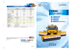
Download Technical Specifications Fort Wayne International Airport
Transcript
FAA AC 150/5220-20 Technical Specifications Fort Wayne International Airport Specifications for two Airport Snow Removal Vehicle with Heavy Duty Single Frame 4X4 Chassis, Forward Mounted Cab, 24 Foot Plow with Hands Free Hitch and 22 Foot High Performance Underbody, Mid-Mount Broom 1-15-14 These specifications contemplate the furnishing and delivery of two new Airport Snow Removal Vehicle with Heavy Duty Single Frame 4X4 Chassis, Forward Mounted Cab, Airport Runway Plow with Hands Free Hitch and High Performance Underbody, Mid-Mount Runway Broom. The requirements listed for the Airport Snow Removal Vehicle with snow plow and Mid-mount broom as outlined are based upon the current Federal Aviation Administration (FAA) Advisory Circular (AC) 150/5220-20 and is designed to facilitate the purchase of equipment that has been found acceptable to the FAA for use on airports. CHAPTER 1. OVERVIEW. Compliance 1. BACKGROUND. Runways and taxiways should be maintained, if possible, to a "no worse than wet" condition during inclement weather. To meet this challenge, the purchase of snow and ice control equipment will not only require significant financial commitments, but also careful planning. Selection of equipment is based to a large extent on manufacturer's specifications. 2. CLASSIFICATION. Snow and ice control equipment is generally classified by category based on the specific task that the equipment was designed to perform. This AC discusses several of these categories, e.g. rotary and displacement plows, material spreaders, and carrier vehicles. 3. CONTENT. Chapters 1-7 describe this equipment and present methods of selecting and testing that will meet sponsor needs and ensure compliance with manufacturer's claims. The remaining portion of the AC deals with equipment specifications. For example, appendix 1 contains specifications for a generic carrier vehicle while appendix 2 lists equipment options available for carrier vehicles, rotary plows, displacement plows, and material spreaders. Appendices 3, 4, and 5 cover specifications for rotary plows, displacement plows, and dry and liquid spreaders. 4. FRICTION TESTING EQUIPMENT. NOT USED IN THIS PROCUREMENT. 5. USE OF SPECIFICATIONS. These specifications can be used individually or in combination with one another. For example, an airport operator desires to acquire a new self-propelled rotary plow. This unit consists of a carrier vehicle and a rotary plow head assembly. The operator would combine information in Appendix 1 with Appendix 3 and, if necessary, appropriate parts of Appendix 2 for the required specification. On the other hand, if only a rotary plow head assembly were required, Appendix 3 is all that is needed. 6. VARIABLE USE OF EQUIPMENT. Depending upon conditions, a displacement plow supported by a sweeper may be all that is required to keep an airport open to traffic. At other airports, more diverse equipment may be needed. In assessing airport needs, the airport operator must compare the cost/benefit relationship of acquiring a multifunctional piece of Page 1 of 34 FAA AC 150/5220-20 equipment offering a number of attachments versus the acquisition of a single unit designed primarily to accomplish one task. 7. CERTIFICATION. Purchasers of equipment described in this AC should obtain a certification in writing from the vendor that the components constituting the whole of the equipment being supplied comply with the applicable performance, design or construction requirements of this specification. This certification is required if the equipment is purchased with Federal funds. In this event, a signed copy of the certification shall be made part of the equipment documentation. __________ 8 and 9. RESERVED CHAPTER 2. ROTARY PLOWS NOT USED IN THIS PROCUREMENT. CHAPTER 3. DISPLACEMENT PLOWS. NOT USED IN THIS PROCUREMENT CHAPTER 4. MATERIAL SPREADERS. NOT USED IN THIS PROCUREMENT CHAPTER 5. CARRIER VEHICLES. 34. DESCRIPTION. The term carrier vehicle represents the various self-propelled prime movers that provide the power necessary to move snow and ice control equipment during winter operations. Vehicle selection is determined by the mission to be performed and the capacity of the selected equipment. a. Truck Type Vehicles. Truck type vehicles are standard production models designed primarily to meet an airport's snow and ice control needs but also have the ability to perform secondary functions. They may be self-contained, designed specifically for a singular purpose, or they may be multifunctional and equipped for several summer as well as winter tasks. They should conform to the manufacturer's recommendations and be suitable for mounting all specified accessories. __________ b. Special Purpose Vehicles. Not used in this procurement c. Wheel Loader Vehicles. Not used in this procurement d. Industrial 4x4 Tractor Vehicles. Not used in this procurement e. Vehicle Dimension. Vehicle dimensions shown in appendix 1 will permit vehicles to pass through the standard industrial door openings of service and storage buildings (AC 150/522018, Buildings for Storage and Maintenance of Airport Snow and Ice Control Equipment and Materials). These dimensions are also compatible with FAA recommended parking space setasides within these buildings. Additionally, they should permit servicing of equipment by standard lifts and cranes without special equipment or building modification. __________ Page 2 of 34 FAA AC 150/5220-20 35-36. RESERVED. CHAPTER 6. SELECTION OF ROTARY AND DISPLACEMENT PLOWS. NOT USED IN THIS PROCUREMENT CHAPTER 7. OPERATIONAL STANDARDS AND TESTING. 44. GENERAL. The manufacturer shall be responsible for conducting tests to ensure that its snow and ice control equipment meets the operational and performance requirements it advertises. Certified records of these compliance tests shall be submitted by the manufacturer with each response to an invitation to bid. Equipment tests shall be conducted on standard production models and not on specially constructed prototypes. __________ 45. ADDITIONAL TESTS. The purchaser should consider conducting its own operational, performance, and capacity tests on equipment prior to acceptance. The manufacturer should have the opportunity to witness the performance of these tests, but interpretation of results is the sole responsibility of the purchaser. __________ 46. CARRIER VEHICLE TESTS. The following temperature, performance, and compliance tests may be conducted by a purchaser when acquiring a carrier vehicle. a. Cold Weather Operations. A fully-equipped carrier vehicle should be able to perform normal operations at an ambient temperature of: 1) 10°F (-12°C) below the lowest temperature in which the vehicle is expected to operate, or __________ 2) -40°F (-40°C) at airports located in extremely cold climates. __________ b. Hot Weather Operations. The vehicle should be capable of operating at an ambient temperature of 70°F (21°C) at the maximum speed recommended by the manufacturer without any of the vehicle components exceeding their normal operating temperature. __________ c. Power Carrier vehicles shall have sufficient power to perform all operational and attached functions simultaneously. __________ d. Performance. The following tests shall be conducted on a vehicle loaded to its GVW (Gross Vehicle Weight) and shall include the following systems: hydraulic, power train, brake, lighting, controls, and instruments. 1) 10 Mile Test. This test requires that the vehicle be driven over hard surfaced roads at normal airport speeds for a distance of 10 miles (16 km) with no perceptive problems. Special attention shall be focused on vibration, steering, vehicle drift, rattles, leaks, and interior controls. __________ 2) One Hour Test. This is a time test that will be performed at a speed of 5 mph (8 kph) over all types of terrain that would normally be encountered at the airport. __________ 3) Service Brake Test. This test shall be conducted at speeds of 20 mph and 40 mph (32 kph and 64 kph) respectively. Using the service brakes only, the fully loaded vehicle shall be brought to a complete stop within a distance of 35 and 131 feet (11 and 40 m) measured from the point of brake application. The test shall be conducted for two complete cycles in either direction on a hard pavement surface that is dry, reasonably level and free of loose material. During this maneuver, no steering corrections shall be made for vehicle drift during the stop. __________ Page 3 of 34 FAA AC 150/5220-20 4) Emergency Brake Test. This test shall be conducted at a speed of 40 mph (64 kph). Using the emergency brake only, the fully loaded vehicle shall be brought to a complete stop on the most critical airfield pavement grade within a distance of 288 feet (88 m) measured from the point of brake application. The test shall be conducted on a hard surface that is dry and free of loose material. Once stopped, the brake will continue to hold the vehicle without fade for five minutes. During this maneuver no steering corrections shall be made for vehicle drift during the stop. __________ APPENDIX 1 - SPECIFICATION FOR CARRIER VEHICLE. PART A -AIRPORT OPERATOR CHECKLIST. FORWARD: When preparing a solicitation to purchase a carrier vehicle, an airport operator or specification writer should use PART A to identify user requirements and PART B to define the specification to meet these requirements. Part A is important because it tailors the carrier vehicle to the unique requirements of the purchaser, i.e. automatic transmission, diesel engine, heated windshield versus plain etc. Both parts, when combined, become the technical basis for a user’s request for proposal. 1. Anticipated uses and/or features of vehicle. This unit will be used to remove containments from our primary runway and taxiway movement surfaces during winter operations. 2. Turning Radius chassis only, wall to wall......... With AWS, not to exceed 75 Feet __________ 3. Engine/Transmission. a. Diesel b. Automatic c. Number of forward speeds, minimum four, maximum six __________ __________ __________ 4. Transfer case. a. Shall be single or 2 speed type. b. Front Axle Disconnect…Automatic or manual type. __________ __________ 5. Axle capacities Minimum Front 22,000 pounds Minimum Rear 23,000 pound __________ __________ 6. Fuel capacity.... 150 gallons minimum for carrier vehicle __________ 7. Auxiliary equipment. None Page 4 of 34 FAA AC 150/5220-20 PART B - SPECIFICATION FOR CARRIER VEHICLE. 1. MATERIALS. Materials used on a carrier vehicle (vehicle) shall conform to the specifications listed in the FAA advisory circular 150/5220-20, latest edition, and appropriate sections of Title 49, Chapter III, Subchapter B - Federal Motor Carrier Safety Regulations (Title 49). When not specifically listed, materials shall be of the best quality available for their intended commercial use. Component parts shall be new and free of all defects and imperfections that could affect the serviceability of the finished product. __________ 2. DESIGN. Equipment shall be developed in accordance with the best engineering practices available. This includes the incorporation of ergonomic designs specifically directed at the vehicle’s cab environment. Vehicle design shall include current state-of-the-art procedures that consider improved cab visibility, communications systems, interior lighting and the mitigation of noise and vibration. Design and installation of equipment shall permit easy accessibility for maintenance and service. All vehicle stress points shall be designed to distribute and dissipate shock forces. __________ 3. CONSTRUCTION. Vehicle construction shall provide maximum protection against failure of structural members. Equipment shall withstand the cold, moisture, strains, jars, vibration, and other conditions that are likely to be encountered during operation. All components and assemblies shall be free of hazardous protrusions, sharp edges, cracks, or other elements which might cause injury to personnel or damage to equipment. Location of all oil, hydraulic, and air lines and electrical wiring shall be in protected positions properly attached to the frame or body structure. Wherever these lines pass through structural members, they shall be protected with looms or grommets except where a through-frame connector is necessary. __________ 4. CHASSIS. a. GENERAL. The design of the vehicle chassis shall be based on an all-wheel drive concept for optimized performance and safety. It shall have power assisted steering and a transmission with suitable load ranges to accommodate normal operating conditions. A pintle hook shall be permanently attached to the rear frame structure capable of towing a vehicle. All installed parts and accessories necessary for the safe operation of the vehicle shall conform to applicable provisions of Title 49. Structural Members. The frame shall be made of pressed steel channel and reinforced as required to prevent distortion under maximum load conditions. All frames and stiffeners shall be treated with a corrosion inhibitor and shall be primed and painted before assembly. __________ b. Dimensions and Clearances. Carrier vehicles shall have the following overall dimensions: 1. Minimum Ground Clearance. The minimum ground clearance of a vehicle chassis shall be 8 inches (20 cm). __________ 2. Maximum Overall Height. The overall height of a vehicle excluding discharge chutes, lights, and exhaust stacks shall not exceed 13 feet (4.0 m). __________ 3. Maximum Overall Width. The overall width of a vehicle including displacement plows (if specified) at their maximum angle shall be no more than 24 feet __________ 4. Maximum Overall Length. Maximum vehicular length should not exceed 35 feet (l0.7 m) without front attachment for single purpose vehicles. For multifunction single unit vehicles, maximum overall length should not exceed 70 feet. __________ 5. Minimum Turning Circle Diameter. Using two wheel steering only, single purpose vehicle must be capable of turning within a circle whose diameter is 100 feet (30 m). For Page 5 of 34 FAA AC 150/5220-20 multifunction single unit vehicles, multi-axle steering is mandatory. For multi-function single unit vehicles, the maximum turning circle shall be a diameter of 75 feet. This diameter is measured from center to center of the outside front tire tread ground imprint. __________ c. Weight Distribution. The gross vehicle weight of the vehicle shall essentially be distributed equally over its axles. Under normal operating conditions, there shall not be more than a 20 percent variation in weight on any axle. The center of gravity shall be kept as low as possible under maximum load conditions. While it is loaded, the vehicle shall be capable of resting on a 20 percent transverse grade without danger of overturning. __________ 5. ENGINE. The vehicle engine shall be of internal combustion, diesel design having a minimum of six cylinders. It shall be able to meet the performance characteristics specified herein on commercial grade fuel. The engine shall develop sufficient torque and horsepower to meet its normal operational requirements without exceeding the no-load speed at the peak of its certified gross brake horsepower curve. See horsepower specified in Appendix 2. Engine noise and vibration can be reduced in the vehicle cab by placing engines behind the cab. __________ 6. COOLING SYSTEM. a. General. The engine cooling system shall be based on a liquid design. Internal temperatures shall be controlled by a by-pass thermostat that regulates the flow of engine coolant. Even upon failure of the thermostat, the design of the system shall allow the engine to continue temporary operation without overheating. Drain cocks shall be installed at the lowest point of the cooling system and at other points necessary to completely drain the system. __________ b. Coolant Temperatures. Coolant temperatures shall not exceed 212°F (100°C) nor be less than 140°F (60°C) when operated in ambient temperatures during snow removal operations. In areas which frequently experience temperatures below -40°F (-40°C), cooling system heaters, oil pan heaters, lubricating oil heaters, battery block heaters, and vapor start systems are recommended (see Appendix 2). __________ 7. FUEL SYSTEM. a. General. The fuel system shall comply with Title 49. It shall include fuel injectors, fuel pump, fuel strainers, dry filter type air cleaners, fuel lines, valves, drains, return lines, and other accessories required to provide a complete operational system . __________ b. Fuel Tank(s) and Lines. Fuel tank(s) shall have the capacity to supply fuel continuously to the engine(s) for a period of not less than 8 hours while it is operating at its rated horsepower under normal conditions. If dual tanks are used, the supply system shall be designed to ensure an uninterrupted flow of fuel to the engine(s). Fuel lines shall be securely fastened in place, installed to prevent chafing or strain, and protected by grommets where lines project through metal apertures. Each fuel tank is to be equipped with an accessible bronze or brass drain plug or a quick drain. ___________ c. Fuel Filler Pipe. The fuel filler pipe shall be located in an accessible location outside of the vehicle cab. A light chain shall be attached near its opening and to the filler cap to prevent loss of the cap. Left/right crossover connections are required that are rated for sufficient flow to allow filling of saddle tanks from either side without delay. ___________ Page 6 of 34 FAA AC 150/5220-20 d. Air Cleaner. The air cleaner shall be of a two stage design. The first stage incorporates a centrifuging pre cleaner while the second consists of a dry type replaceable paper filter. It shall display an indicator that shows when the dry type paper filter needs servicing. The connection between the air cleaner outlet(s) and the engine intake(s) shall be waterproof and dust tight. The air cleaner intake shall be positioned in a manner to discourage the ingestion of snow and other contaminants, e.g. within the hood cavity. __________ 8. EXHAUST SYSTEM AND MUFFLER. The engine shall be equipped with an efficient and safe exhaust system including mufflers. Its location shall minimize noise and exhaust gases entering the vehicle cab under all operating conditions. Further noise reductions by noise suppression materials, such as muffler insulation, is encouraged. Horizontal portions of exhaust systems shall be protected, whenever possible, from corrosive agents and fuel spills. Exhaust systems shall be positioned on the vehicle in a manner to minimize contact with slush and snow. Muffler(s) are to be made of aluminum, stainless steel, or materials coated with ceramics. Devices shall be installed to prevent snow and slush from entering vertical exhaust stacks. _________ 9. GOVERNOR. Engine speed shall be regulated by a governor set to provide the maximum operating speed recommended by the engine, driveline, and power train manufacturers. __________ 10. LUBRICATION. An engine's lubricating system shall be equipped with standard production fittings and accessories. Engine oil filter(s) shall be of either full-flow or by-pass design with either able to accept commercial replacement elements. All engine(s) shall receive lubrication prior to delivery with lubricants designated for use under ambient temperature conditions at the point of delivery. The unit(s) shall be tagged to identify the proper lubricants and their temperature ranges by means of a lubrication chart on the body. __________ 11. ACCESSIBILITY. a. Component Location. Engine and chassis components shall be positioned to allow easy access for inspection and maintenance purposes. Components that historically present maintenance problems or those that have the potential to cause operational problems should particularly be located in unobstructed areas. Locks, controls, and fasteners shall be designed to prevent over-torqueing. __________ b. Cover Plates. Cover plates shall be equipped with either quick-disconnect fastenings or hinges. __________ 12. TRANSMISSION. Transmission and vehicle manufacturers shall provide an application approval, at the time of vehicle delivery that states the transmission is suitable for use in the vehicle as configured. The transmission shall operate smoothly and efficiently and be capable of transmitting the maximum gross torque generated by the engine to the drive wheels through all gear reductions. Drive trains shall be in conformance with SAE requirements and shall be designed to minimize the number of joints. __________ The torque converter shall not operate at less than 70 percent efficiency. The gear or range selector shall have forward, neutral, and reverse positions clearly identified. __________ Page 7 of 34 FAA AC 150/5220-20 13. TRANSFER CASE. The vehicle and transfer case manufacturers shall provide an application approval at the time of vehicle delivery that states the transfer case is suitable for use in the vehicle, as configured. Transfer case assemblies shall provide positive drive to the front and rear axles and be of optional single or multi-speed design. Three proven alternatives are the manual front axle disconnect type, the center differential with manual or automatic lockout type, or an overriding clutch type, any of which may be selected by a purchaser as an option (see specification checklist above). The transfer case may be a separate unit mounted independently or integrated with the transmission or axle. __________ 14. AXLES. The axle and vehicle manufacturers shall provide an application approval at the time of vehicle delivery that states the front and rear axles are suitable for use in the vehicle, as configured. The axle manufacturer's published rating shall at the least be equal to the load imposed at ground level when the vehicle is at its rated gross vehicle weight (GVW). Each nonsteering axle shall be equipped with a retarding type device to ensure a torque transfer to each wheel having traction. When appropriate, manual lockout controls shall be located in the vehicle cab. The torque capacity of each axle and differential shall be at least 10 percent in excess of the maximum torque that the axle may experience under any GVW operating condition. The power transmitting shaft on a steering axle shall incorporate steering joints that do not produce objectionable steering characteristics while the vehicle is operating on uneven surfaces. __________ 15. BRAKE SYSTEM. A vehicle service and emergency braking systems shall meet Title 49 requirements for vehicles of similar design. These systems, whether air, hydraulic, or of another design, shall be complete with all necessary equipment to safely control, stop, and hold a fully equipped vehicle under all normal operating conditions. Both systems shall be readily accessible for external adjustment. An ABS system (minimum 4S 4M) is required regardless of axle weight rating. __________ 16. STEERING MECHANISM. The vehicle shall have a power assist steering mechanism which is operated from the driver's seat. During normal operations, the mechanism shall be capable of controlling the vehicle with all equipment operating. The design of the steering mechanism should, in the event of a power assist failure, be capable of safely bringing the vehicle to a park position from the maximum design speed allowed on the airport. __________ 17. SUSPENSION SYSTEM. Vehicles shall be equipped with a current production model suspension system having a minimum rated capacity equal to the GVW of the carrier vehicle. System capacity may be determined by taking measurements from ground level with the vehicle loaded to its rated GVW and the attached equipment in its storage position. When required, front and rear axles shall have auxiliary suspension springs. Manufacturer's capacity ratings may not be raised to conform to the requirements of this specification. The suspension system shall exhibit no permanent set after the load is removed. __________ 18. WHEELS, RIMS, TIRES, AND TUBES. a. Wheels. Rim and tire ratings shall conform to the published recommendations of the Tire and Rim Association. __________ b. Tires. Each tire shall have a rated carrying capacity at least equal to the loads imposed on them by a fully loaded vehicle measured at each wheel. Tires on each axle shall be of the same size, except where dual tires require different sizes, and they shall have an aggressive tire tread. Tires (and tubes when applicable) shall meet the first line commercial grade Page 8 of 34 FAA AC 150/5220-20 requirements for the speed and type of service required. The front and rear tread widths shall not vary by more than four percent. __________ c. Spare Rim/Tire. Provisions for carrying the spares on the vehicle are not necessary. __________ 19. HYDRAULIC SYSTEM. a. General. The hydraulic system shall consist of appropriate rams, pumps, piping, fittings, valves, controls, fluid reservoirs and filters, coolers, and other parts essential to its full operation. The system shall be capable of hydraulically positioning equipment through the entire range of its design limits. It shall be capable of operating all controls simultaneously without a noticeable reduction in power response. All hydraulic controls shall be located in the vehicle cab. The system shall be ruggedly constructed and able to withstand all loads imposed on it without relying on the use of mechanical locks. Filters within the hydraulic system shall conform to the Society of Automotive Engineers (SAE) Information Report, SAE J 931- Hydraulic Power Circuit Filtration. __________ b. Pump and Power Takeoff. The pump shall be ruggedly constructed and powered by the engine through a crankshaft power takeoff. It shall have sufficient capacity to operate the hydraulic equipment specified herein under all operating conditions and speeds. Belt driven hydraulic pumps are not acceptable. __________ c. Lines and Fittings. Only commercial quality hydraulic lines, hoses, and fittings capable of withstanding system working pressures under load are acceptable. Hydraulic hoses shall have a bursting pressure of three times their rated working pressure. The use of fittings, joints, and connections shall be kept to a minimum. __________ d. Fluid Tank. The hydraulic fluid tank shall have a filler neck consisting of a strainer, drain plug, air vent, and baffles. Its capacity shall exceed the volume of oil required for the operation of any combination of attachments by 50 percent, and it shall have a hydraulic fluid quantity level measurement. __________ e. System Winterization. The hydraulic system shall meet the same low temperature requirements as the engine coolant system. __________ 20. ELECTRICAL SYSTEM. a. General. The electrical system shall be negatively grounded and installed in accordance with current state of the art practices and appropriate Federal requirements. All parts of the electrical system shall be waterproof, easily accessible, securely mounted, and protected against extreme temperatures, physical damage, snow, oil, and corrosion. All electrical circuit wiring shall be made of stranded conductors with a capacity exceeding the anticipated maximum circuit loading. Insulation of electrical wiring shall be equal to the recommended standards established for insulation materials by the Society of Automotive Engineers (SAE). __________ b. Power Supply. The carrier vehicle shall be equipped with a self-regulating electric alternator having an output capacity that exceeds the anticipated electrical load. __________ Page 9 of 34 FAA AC 150/5220-20 c. Batteries. Batteries shall be securely mounted and adequately protected against physical injury, water, chemicals, and exhaust heat. They shall be properly sized based on vehicle manufacturer recommendations and be readily accessible for change out and for other purposes. Enclosed battery compartments shall have adequate ventilation. Battery capacity (cranking amps, voltage, reserve power, continuous/deep cycle demand) shall be compatible with the size of the engine and the anticipated electrical load expected under normal operating conditions. Minimum battery size to start the engine shall be rated at 120 ampere-hours over a 20-hour discharge rate. __________ d. Starting Device. The vehicle shall have an electrical starter that shall not introduce a voltage drop sufficient to affect adversely the ignition system. It shall be equipped with an overload protection device. One of the following electrical/starting systems shall be provided: 1) 12 volt electrical and starting. 2) 12 volt electrical/24 volt starting. 3) 24 volt electrical and starting. __________ e. Ignition System. Ignition systems for diesel engines may be equipped with or without glow plugs, depending on make, model, and manufacturer. Under extreme weather conditions, a block heater should be considered for improved ignition. __________ f. Sounding Device. Excluding pick-up trucks, each vehicle shall be equipped with an audible sounding device that is activated when the vehicle is shifted into reverse gear.__________ 21. LIGHTING SYSTEM. The lighting system, including reflectors and clearance lights, shall be standard equipment currently used by the manufacturer. Task-oriented lights should be capable of lighting those areas to be cleared. __________ The system shall include: a. Headlights. The carrier vehicle shall be equipped with two or more sealed-beam quartzhalogen or equivalent headlights with upper and lower driving beams and a hand controlled switch for beam selection. Snow removal attachments and other accessories should not be positioned so as to obstruct the illumination of these lights. __________ b. Dual Tail lights and Dual Stop lights. Each vehicle operating on airport property shall be equipped with dual tail lights and dual stop lights. The stop lights shall be activated whenever service brakes are applied. __________ c. Turn Signals. The carrier vehicle shall be equipped with two front and two rear turn signals that conform to SAE Turn Signal Units, Type I Class A, with self-cancelling controls and a visual/audible indicator. In addition to signaling turning movements, the system shall also be capable of signaling a hazardous condition by flashing simultaneously with the ignition of the vehicle turned on or off. __________ d. Spotlight. There shall be a corrosion resistant spotlight securely mounted near the cab roof. __________ e. Reflectors, Markers, and Clearance Lights. This equipment shall conform to the requirements of Title 49. The clearance lights shall have commercial truck lenses. Page 10 of 34 FAA AC 150/5220-20 __________ f. Engine Compartment Lights. These lights shall adequately illuminate both sides of the engine(s). Location of the switches shall be in the engine compartment(s) with proper clearances so that they can be activated by operators wearing heavy winter gloves and outer garments. __________ g. Backup Lights. There shall be at least two backup lights installed at the rear of and at either side of the vehicle that will automatically be activated when the vehicle is shifted into reverse gear. __________ h. Vehicle Safety Identification Lights. The vehicle shall have a minimum of one flashing yellow strobe, mounted on its uppermost part (see AC 150/5210-5B, Painting, Marking, and Lighting of Vehicles on an Airport). The light emitted from the strobe should not reflect off rearview mirrors and into the operator's eyes. The flashing strobe shall have the following characteristics: 1) 360° azimuth (horizontal) coverage. 2) peak intensity from 0° to 10° above the horizontal and reduced intensity to 1/10 of peak intensity from 10° to 15° above the horizontal. __________ 22. OPERATOR'S CAB. a. General. Carrier vehicle cabs shall be made of either metal or fiberglass construction. They shall be fully enclosed accommodating a single operator plus assistant/trainee (full cab). A definite separation shall exist between the engine and operator's compartment. All non-glass surfaces, such as the floor, sides, and roof of the cab, shall have insulation to reduce exterior noise. The maximum interior cab noise measured at the operator's seat shall not exceed 85 dBa under the following conditions: windows closed, heater and defrost systems at maximum operation, and carrier vehicle and equipment engines operating at maximum rated capacity. To the extent possible, the interior of the cab shall be ergonomically designed providing the operator with a pleasant working atmosphere that is devoid of the stark conditions normally associated with older equipment. __________ b. Communications Equipment Space. Transceivers shall be installed in carrier vehicles to establish voice communication with other vehicles, the air traffic control tower, snow control center and maintenance facilities. The vehicle cab shall be designed to provide convenient space near the operator for the installation of a pair of transceivers. __________ c. Fire Extinguisher. The vehicle cab shall have at least one 2A-10BC interior mounted fire extinguisher that is readily accessible to the operator. __________ d. Operator Seat. The vehicle cab shall provide an operator and trainee seat that can easily be adjusted up and down, fore and aft, a minimum of three inches (7.6 cm) in each direction. The seat should also be capable of reducing the effect of vehicle vibration by featuring aircushion shock absorbing seat systems. Adjustable lumbar required for both cab seats. All vehicle seats shall have approved seat belts. Seats shall be fully upholstered with a good quality fabric or plastic material. __________ e. Windows. The vehicle cab shall maximize the use of glass, including the placement of panels if possible in the lower sections of door panels, to increase the operator's view of operational areas and ground surfaces. All installed glass shall be laminated and safety Page 11 of 34 FAA AC 150/5220-20 rated. The location and size of the windshield shall minimize visual obstructions to the operator. The windshield shall be designed to avoid snow buildup and be equipped with at least one two speed automatically operating wiper (standard or wet) that is capable of sweeping a clear view for all occupants. The windshield washer reservoir shall have a capacity of at least one-half gallon (2 liter). Fluid applicators shall be located to provide at least 75% coverage to the windshield. The cab shall be equipped with sun visors. __________ f. Exterior Rearview Mirrors. Two electrically heated, remote control exterior rear view mirrors of the extension arm type shall be mounted on each side of the vehicle cab. Each mirror shall have an area of not less than 100 in2 (650 cm2). __________ g. Heater-Defroster. 1) Heating System. The carrier vehicle cab shall have a heating system that is capable of maintaining a minimum interior temperature of 65° F (18° C) at an ambient outside temperature of -20° F (-29° C). Heat output shall be controllable from within the cab by a selector switch that is conveniently located to the operator. Under all conditions of heating and ventilation, the temperatures measured in the operator's immediate environment should be uniform within 9° F (5° C) (see SAE J 1503, Performance Test for Air-conditioned, Heated and Ventilated off-Road Self Propelled Work Machines). __________ 2) Windshield. Windshields and other glass surfaces in the vehicle cab used in the operation of the vehicle and or to view pavement surfaces, including rear windows if installed, shall be defrosted through a heat energy transfer system. The front windshield shall be electrically heated. __________ h. Ventilation. Each vehicle cab occupant should receive a minimum of 25 ft3/m (.71 m3/m) of filtered fresh air under all heating and ventilating conditions (see SAE J 1503). Cab ventilator intakes should be screened and positioned in such a manner to minimize the entry of snow. __________ i. Hour meters. Every engine permanently attached to a carrier vehicle shall be equipped with an hour meter that registers engine operation time from zero to 9999 hours. Hour meters shall be prominently displayed so that they can be easily read by an operator or service personnel. __________ j. Instrumentation. The cab shall display an instrument panel equipped with rocker, push button, and/or toggle switches and controls (instruments) that are user friendly to operators wearing bulky winter clothing. Toggle switches, where used, shall have a minimum length of 1 1/2 inches (4 cm). Frequently used instruments shall be located in direct line-of-sight and within forearm reach of a medium-sized person sitting in the operator's position. All instruments shall be clearly identified with labels that indicate their function. Instruments should display urgency-of-action lights, i.e., green for normal operation, amber for warning, and red for emergency. Instruments shall be illuminated by background lighting regulated by dimmer switches capable of providing infinitely variable lighting intensities. Circuit breakers shall be grouped for easy access and convenience. __________ Typical instruments that report and track major functions of a carrier vehicle are as follows: 1) Engine. a) Voltmeter. __________ Page 12 of 34 FAA AC 150/5220-20 b) Lubricating Oil Pressure Gauges. c) Coolant Temperature Gauge(s). d) Tachometer(s) including hour meter(s). e) Starting Controls (including auxiliary cold start controls). 2) Vehicle Chassis. a) Brake-air Pressure Gauges. b) Low-air Pressure Warning, visual and audible type. c) Light Switches and Headlight Beam Indicator. d) Speedometer with Recording Odometer. e) Fuel Quantity Gauge(s). f) Equipment Controls. __________ __________ __________ __________ __________ __________ __________ __________ __________ __________ 23. SHEET METAL COMPONENTS. a. General. The carrier vehicle engine, as well as its mechanical components, shall be protected wherever possible from snow, rain and other winter elements. Body and engine enclosures shall be fabricated from aluminum, fiberglass, and steel. Self tapping bolts are unacceptable in the construction of these enclosures. __________ b. Body Accessories. The following parts and accessories are necessary for operational safety: 1) Steps. Four-way safety tread design steps are required. These steps, together with assist handles, shall be of ample size to ensure safe and easy access for persons wearing bulky winter clothing. __________ 2) Walkway. A four-way safety tread design walkway shall be provided, as necessary, for access. __________ 3) Handrails. Handrails shall be provided as required at all steps walkways, and work stations. They shall be made of corrosion-resistant materials or otherwise treated to prevent corrosion. __________ 4) Fenders. All carrier vehicles shall be equipped with fenders and when determined by the operator, non-sail mud flaps to prevent wheels from throwing snow and other debris. __________ 5) Drains. Plugged or free flowing drains shall be provided at all body and compartment locations where standing water can collect. Free flowing drains shall not drain onto sensitive mechanical or electrical components or on areas anticipated to be occupied by personnel during normal operations. __________ 6) Doors. Doors shall be equipped with a positive closing mechanism and, where appropriate, a locking mechanism. Top hinged compartment doors shall be held in the open position by support arms. __________ 7) Gutters. The vehicle cab shall be equipped with gutters, located above the entrance doors, of sufficient length to span the door width and provide runoff protection to occupants either entering or exiting the cab. __________ 24. PAINTING, MARKING, AND LIGHTING OF VEHICLES. a. Painting and Marking. The vehicle shall be painted Chrome-Yellow in accordance with color tolerance charts that have been made available for FAA regional airport inspectors and key potential users in the aviation safety equipment industry (see AC 150/5210-5B). __________ 1) Preparation and Finish. The carrier vehicle and all mounted and towed equipment shall be cleaned first, then treated with a corrosion inhibitor, primed, puttied, sanded, and finally painted. The paint shall consist of not less than two coats of Chrome-Yellow polyurethane enamel having a combined minimum thickness of 7 mils. __________ Page 13 of 34 FAA AC 150/5220-20 2) Quality. The finished paint shall be free of "fisheye", "orange peel", chips, runs, or other imperfections that detract from the equipment's corrosion resistance and appearance. __________ 3) An 8” white reflective stripe is required on sides of vehicle __________ 4) Chevron striping is required on rear bumper __________ 5) Airport name and number designation required on sides and top: __________ Logo as supplied by airport to be applied on each side of unit The number __ each side in 18” high numbers, and on the top in 24” numbers Airport Name shall be applied to each side as directed by the airport 25. MISCELLANEOUS. a. Name, Service, and Instruction Plates. All information plates shall be made of either noncorrosive metal or plastic with the information engraved, stamped, or etched thereon. Plates shall be mounted in a conspicuous place with screws, bolts, rivets, or exterior type pressure sensitive tape. __________ 1) Plastic plates. Plastic plates are acceptable only in locations that are not exposed to the elements and subject to weathering or excessive heat. __________ 2) Information. Plates shall identify make, model, serial number, and any other relevant data. __________ b. Technical Publications. The manufacturer shall furnish two electronic sets of the following publications: 1) Operator's Manual. The operator's manual includes lubrication charts and instructions (two paper copies of operator’s manual also required). __________ 2) Parts Manual. The parts manual identifies and lists all parts, components, and subassemblies used in the fabrication of the carrier vehicle. __________ 3) Maintenance and Service Manual. A maintenance and service manual provides guidance to non-specialists performing routine services. The manual should also describe in detail with appropriate schematics the overhaul and major maintenance procedures required to maintain the vehicle. __________ c. Accessories and Tools. The carrier vehicle shall be provided with the following tools and accessories. 1) Tire Tools. __________ 2) Jack. A jack specifically adapted to the carrier vehicle that is capable of raising it to a position where a flat tire can be changed. __________ 3) Specialized Tools. Specialized tools required for routine servicing of the carrier vehicle and its auxiliary equipment. __________ 26. DELIVERY. a. Preparation for Delivery. 1) Shipment. The vendor "seller" is responsible for the safe and timely delivery of the vehicle and its accessories, spare parts, and tools to the agreed place of delivery. __________ 2) Marking. Carrier vehicles shall be marked for shipment in accordance with instructions agreed to by the purchaser. __________ b. Instruction and Training. The manufacturer shall, at no additional cost, furnish the services of trained personnel to the purchaser at a time and place agreed to by all parties. These individuals shall provide instructions to airport personnel sufficient for the personnel to Page 14 of 34 FAA AC 150/5220-20 familiarize themselves with the operational and maintenance characteristics of the vehicle and its auxiliary equipment. The period of instruction shall not be less than 24 hours. __________ Appendix 2 APPENDIX 2 - OPTIONAL/ALTERNATE EQUIPMENT SPECIFICATION. 1. GENERAL. Most snow and ice control equipment is designed to operate under normal winter conditions. At various times, working tolerances and/or severe weather or operating conditions require specialized support equipment to assist the primary unit prior to or during operation. Several of these options are discussed below: 2. CARRIER VEHICLE. a. Engine 1) Engine block Heater, 1500 watts minimum. __________ 2) Engine Oil Pan Heater. 300 watts __________ 3) Battery Warmer Pad. Approximately 50 - 100 watts per battery __________ 4) 385 Horsepower min Carrier engine __________ 5) Coolant filter __________ 6) 385 Horsepower on road engine __________ 7) 500 Horsepower on road engine __________ b. Vehicle Cab. 1) Auxiliary Cab Heater __________ 2) Circulating Fans in cab (2). __________ 3) Deluge system, 20 gallon reservoir, 5 gpm pump, four nozzles over windshield, one over each side windows, and one on each rear view mirror. (NOTE Deluge requires side window wipers) __________ 4) Side window wipers for door windows. __________ 5) Heated side window wipers for door windows. __________ 6) Heated front windshield wiper blades __________ 7) Rear view color camera and monitor, to include auto-on in reverse, with rear facing dedicated spotlight, with image displaying on LCD control screen in cab. __________ 8) Additional Lighting. 10 sets of lights only exclusive of headlights and clearance lights a) (1-5) sets of HID lights mounted on front light bar with control switch for each set. __________ b) One set of 50 watt halogen flood lights mounted on light bar __________ c) One set of flood lights mounted to rear of vehicle, to illuminate with the standard back up lights when unit is shifted into reverse. __________ d) One set of HID lights mounted at rear of vehicle, to illuminate with the standard back up lights when the unit is shifted into reverse. __________ e) Additional strobe near the rear of vehicle to match cab mounted strobe, both operated by a single switch. __________ c. Mechanical 1) Autolubrication system, Groeneveld or equal 2) Quick disconnect air system connection at left of vehicle 3) 12 inch deep straight rear bumper to protect the vehicle 4) 12 inch deep swept rear bumper to protect the vehicle Page 15 of 34 __________ __________ __________ __________ FAA AC 150/5220-20 5) Centrally located drain system for engine oil(s), engine coolant(s), hydraulic reservoir(s) if applicable, and broom pump drive (if applicable). Labels, quarter turn ball valves, and screw-on caps required. __________ 6) Special Starting Systems. a) Ether Cold Starting System, automatically controlled by engine CPU. __________ b) Stay warm vehicle control system programming __________ 7) Permanently Installed Battery Charger. a) Maintenance Charging, 20 amp self regulating __________ b) Trickle charging, 1-1/2 amp self regulating __________ 8) Engine Cooling. a) 1500 Watt engine block heater with 110 volt plug-in __________ b) Antifreeze mix to -50 degrees __________ 9) All Wheel or Articulated Steering. For all-wheel steering systems, selection shall be available for standard 2-wheel steer, 4-wheel coordinated through steering wheel, 4wheel crab through steering wheel, and independent rear steer via rocker switch on joystick. When in two wheel steer, a spring loaded lock pin shall lock rear axle in the straight ahead position. System shall be speed dampened but available in all forward and reverse gears. __________ CHAPTER 8. AIRPORT SNOWSWEEPER 53. DESCRIPTION. Snow sweepers (sweepers) are primarily used in the high-speed sweeping and cleaning of snow and debris from airport operational areas. They incorporate high speed brooms that consist of a number of brush sections which may be front mounted to a carrier vehicle (integral or attached), underbody mid mounted on the carrier vehicle chassis or mounted on a trailer arrangement towed by a carrier vehicle. All are capable of sweeping wet slushy snow as well as fine dry snow from pavement surfaces. The sweeper framework shall be designed to provide continuous service under difficult working conditions in cold climates. A sweeper may be complimented by an air blast system which is located behind the brush assembly. The sweeper air blast system is used to; sweep the pavement area clean of snow, slush, sand and other debris, help dry the pavement surface, and clear snow from around runway lights. 54. SWEEPER TYPES. Four different types of sweepers are being used worldwide on airports i.e. pushed, towed, carrier chassis mid-mounted underbody, and band type sweepers. The pushed type sweeper precedes the carrier vehicle and allows the operator to directly observe the area being swept. The towed type sweeper is fixed to a trailer and is towed by a conventional carrier vehicle. The operator observes the area being swept by use of mirrors and must maneuver the carrier vehicle and trailer together by carefully observing their outer dimensions. The underbody airport sweeper is a large multi-purpose unit of trailer, semi-trailer or ridged frame design that is pulled by or is mid-mounted and integral to the carrier vehicle and is capable of plowing and sweeping snow and debris simultaneously. Underbody sweepers are mounted amidships of the carrier vehicle and behind the cab. The band sweeper precedes the carrier vehicle much like the broom on a pushed sweeper. However, instead of using a broom, it uses a continuously turning horizontal band that is made of reinforced rubber. The band has a Page 16 of 34 FAA AC 150/5220-20 number of protruding vertical ribs that are capable of moving snow to the right and left of the travel path. 55. CLASSIFICATION. The following two general classes constitute the family of airport sweepers. a. Small Swath Sweeper. Not used in this Procurement b. Large Swath Sweeper. This sweeper class may be of any physical design having a demonstrated or manufacturer's certified snow or slush removal and broadcasting ability sufficient to produce clear pavement within the swath width at the rated speed. The sweeper shall have a minimum broom diameter of 46 inches and a swath width greater than 12 feet (3.7m). All swath widths shall be measured when the broom is angled 30 degrees from the transverse position. __________ 56. COMPONENT PARTS. Materials used on the sweeper and its carrier vehicle shall conform, where appropriate, to the specifications contained in this advisory circular. Accessories and attachments shall be the manufacturer's standard commercial product. Components should be readily accessible for repair and replacement, with minimal removal or disturbance to adjacent parts or components. Parts, such as grommets and bushings, which are exposed to wear, shall be capable of being replaced. Regular maintenance and servicing should be readily accomplished under normal working conditions. __________ 57. PUSHED TYPE SWEEPERS. Not used in this Procurement 58. TOWED TYPE SWEEPER. Not used in this Procurement 59. CARRIER CHASSIS MID-MOUNTED UNDERBODY SWEEPER. This sweeper type may be of any suitable commercial design which is mid-mounted to carrier vehicle. These sweepers are available in straight mechanical, variable speed mechanical, and variable speed hydrostatic drive with some hydrostatic units capable of driving the larger high speed high capacity large diameter brooms similar to those found in the self-propelled units. The full system consists of a carrier vehicle with integrated rigid single frame supporting the brush assembly. The brush assembly may be held by casters, as primary or secondary pavement clearance devices, while the entire assembly is supported by pneumatic tires mounted to the carrier vehicle. The brush assembly is attached to the frame via a DIN hitch. __________ a. Engine Location. The engine is located behind the brush assembly generally above the load carrying wheels of the chassis. __________ 60. BRUSHES. The focal point of any sweeper is the brush. It must not only sweep snow and slush from pavement surfaces at speed, but it must also lift and broadcast these materials off the surface and away from the path of travel. Brushes come in different shapes and sizes and when worn or broken, generally can be easily replaced without causing undue downtime delays to the sweeper unit. Brushes may be mounted on a single tubular core or several abutting cores that receive power directly from the carrier vehicle engine or an independent engine. Choices in brush design and bristle composition provide users with a Page 17 of 34 FAA AC 150/5220-20 wide selection from which to choose to best meet their particular needs. Generally, brushes that display a mixed polypropylene/wire bristle composition will provide best overall sweeping results. Brushes are most effective when their contact with the pavement surface produces a "flicking action" that dislodges snow and slush and leaves a clean dry surface behind. __________ a. Brush Geometry. Three different types of brushes are available for use on airport sweepers, i.e., wafers, tufted wire sections, and cassettes (see Figure 8-3). 1) Wafers. Wafers are by far the most popular type of brush used on airports. They come in either straight or convoluted sections and are fastened to the brush core by pins or other devices. Spacers are inserted between straight wafers to ensure continued separation resulting in an effective full width sweeping pattern. Convoluted wafers, available only in 36 inch (91cm) brushes, do not require spacers because of their unique design which results in a side-to-side reciprocating action that eliminates streaking. __________ 2) Tufted Wire Sections. Not used in this procurement 3) Cassettes. Not used in this procurement. b. Bristles. Brush bristles are made of polypropylene plastic (poly), wire, or a combination of one-half poly and one-half wire. __________ 1) Polypropylene. The "poly" brush is a cleaning brush that is superior at lifting and moving non-frozen materials such as dry or loosely compacted wet snow from a pavement surface. __________ 2) Wire. The wire brush is capable of penetrating and loosening hard compacted snow and ice, but does not perform well in throwing the material from the path of travel. __________ 3) Poly/wire. Over 90 percent of the brushes used on U.S. airports are made of onehalf poly and one-half wire materials. This bristle structure combines the best qualities of the pure poly and wire brush in their ability to dislodge and move snow and Ice. __________ 61. SELECTING A SWEEPER. a. Variable Speed Brooms. By utilizing infinitely variable speed hydrostatic drive, a sweeper can be operated in a manner that optimizes its effectiveness in favorable wind conditions and minimizes deterioration of effectiveness in unfavorable conditions. Variable speed also optimizes brush life. __________ b. Larger Diameter Brushes. Relative to their smaller diameter equivalents, larger diameter brushes provide a more effective bristle attack angle, create lower particle projection, develop higher sweeping speeds and sustain longer brush life. __________ c. Convoluted Wafers. Not used in this procurement Page 18 of 34 FAA AC 150/5220-20 62. PERFORMANCE AND TESTING. In accordance with paragraph 44, the manufacturer shall certify that its equipment meets the advertised operational and performance specifications, tests to verify the manufacturer’s claims is required upon delivery. The information contained in this section will assist the purchaser in conducting verification tests. a. Pre-Testing. Each test vehicle shall be examined to ensure that it is a standard production model and not a specially constructed unit made specifically for the test. Prior to testing, all controls, adjusting mechanisms, hydraulic systems and other assemblies shall be operated to ensure against leaks, restrictions and malfunctions. Once assured that the unit is fit, actual testing may begin. __________ b. Carrier Vehicle. The carrier vehicle, fully equipped and loaded to its gross vehicle weight with brush and blower in transport position, shall meet the physical requirements of Appendix I, paragraph 4a and the testing requirements of paragraph 46. __________ c. Sweeper. Testing should be conducted on a runway or taxiway having a length of at least 1000 feet (305m). Snow depth can vary, but the sweeper should be capable of removing snow at the following depths and densities: 1) Small Swath Sweeper. Two inches (5 em) of light snow having density of 8 to 15 lblfe (128 to 240 kg/m3) or one-half inch (1.3 cm) of slush at density of 40 lblfe (641 kg/nr'). __________ 2) Large Swath Sweeper. Three inches (7.6cm) of light snow having density of 8 to 3 15 lb/ft (128 to 240 kg/m3) or one inch (2.5cm) of slush at density of 40 Ib/ft3 (641 kg/m'). Testing speed should be as high as practical but no less than 8 MPH (13 KPH) for small swath sweepers and 25 MPH (40 KPH) for large swath sweepers. The resulting swath width should be reasonably clean without snow deposits resulting from bouncing or skipping of the brush __________ Sweepers shall be capable of varying their brush rotational speed, angle of attack, and the degree of brush pressure applied to a surface area. The unit shall be able to start and perform normal operations at an ambient temperature of 10°F (_12°q below the lowest temperature in which the sweeper is expected to operate or -40°F (-40oC) at airports located in extremely cold temperatures. The unit must be capable of broadcasting snow to either side of the vehicle. The sweeper shall be designed to allow all performance and monitoring functions to be controlled or observed by a single operator from the carrier vehicle cab. The brush should show no performance degradation when sweeping thin deposits of sand, ash, water or other light debris. __________ d. Air Blast, The air blast system shall be operated under the same conditions outlined for the sweeper, and shall meet the requirements specified in Appendix 6, paragraph 4e. __________ 62·64 RESERVED. Page 19 of 34 FAA AC 150/5220-20 APPENDIX 6. SPECIFICATIONS FOR SNOWSWEEPERS PART A • AIRPORT OPERATOR CHECKLIST FORWARD: When preparing a solicitation to purchase a sweeper system, an airport operator or specification writer should use PART A to identify user requirements and PART B to define the specification to meet these requirements. Part A is important because it tailors the sweeper to the unique preferences of the purchaser, i.e. special lighting, pushed versus pulled equipment, air blast system, unique safety equipment etc. Both parts, when combined, become the technical basis for a user’s request for proposal. 1. Anticipated uses and/or features of sweeper: This unit will be used to remove containments from our primary runway and taxiway movement surfaces during winter operations. 2. 3. 4. 5. 6. Primary surface area to be swept in Sq.Ft. 5,337,500 sqft Critical time required to sweep primary surface areas 90 Minutes Sweeper speed needed to meet critical time in MPH 25 MPH Type of sweeper desired: U n d e r b o d y Carrier Chassis Mid-Mounted Underbody a. Air blast system Yes 23,000 CFM at 250 MPH 7. Size of Broom: Length: 18feet Diameter: 46 inch 8. Type of Brush: Poly/wire mix 9. Brush Geometry: Wafer 10. Optional Equipment. See list at end of specification, Section 6. __________ __________ __________ __________ PART B - SPECIFICATIONS FOR SNOWSWEEPER 1. MATERIALS. Materials used on the snow sweeper shall conform to the specifications listed in this advisory circular. When not specifically listed, materials shall be of the best quality available for their intended commercial use. Component parts shall be new and free of all defects and imperfections that could affect the serviceability of the finished product. __________ 2. PUSHED TYPE SWEEPERS. a. Brush Frame. The brush frame, which supports the brush assembly, shall be connected to a push mount, located in front of the carrier vehicle. __________ b. Caster Location. Sweepers shall be equipped with either two ( w i t h b r o o m s 1 8 f t a n d s m a l l e r ) , or four ( w i t h b r o o m s 2 0 f t a n d l a r g e r ) , equally spaced heavy duty swivel type casters mounted on the rear of the brush frame. __________ c. Engine Skid Assembly. When the engine is located on a carrier vehicle chassis, it may be mounted directly to the frame or on a metal skid which fits on the bed area of the Page 20 of 34 FAA AC 150/5220-20 chassis. If designed to be removable, the skid assembly shall be designed for easy installation by overhead crane or forklift. It shall be equipped with two channel members, one on each side of the skid, to enhance safe movement and adjustment. A fuel tank, sufficient for 8 hours of continuous engine operation, shall be included with the skid assembly. __________ 3. TOWED TYPE SWEEPER. Not used in the procurement 4. CARRIER CHASSIS MID-MOUNTED UNDERBODY SWEEPER a. The carrier frame shall be single frame designed for mounting the sweeper assembly midway between the carrier vehicle’s front and rear axles. The frame shall be properly balanced and fabricated of heavy gauge structural tubing, channel, or wide flange members reinforced as required to prevent distortion under load. Provisions shall be made for attaching engines, vehicle hitches, drives, casters, controls, brush mounts and other hardware needed for operation. __________ b. Caster Location. The brush frame, which is an integral but independent part of the, shall be mounted on swivel caster wheels. These wheels are fixed along the rear of the frame and if more than two are used, they should be evenly spaced for uniform weight distribution. __________ c. Wheels and Steering. The non castering wheels shall be the heavy duty automotive type with pressed steel rims and hubs. The sweeper shall be guided by the carrier vehicle. __________ 5. COMMON EQUIPMENT. The following items are common to carrier chassis midmounted underbody sweepers: a. Brush Assembly. The brush assembly shall consist of a vehicular attachment mechanism, cylindrically shaped core, brush frame, hood and deflector, angling system, drive system, and casters. __________ 1) Vehicular Attachment. The brush assembly shall be designed for quick attachment to and removal from its carrier vehicle or trailer. Once attached, it shall be capable of sustaining all loads, including side loads. The assembly shall not transmit bounce or oscillatory motion to the carrier vehicle and shall permit normal operational turning without binding or damage. __________ 2) Core. The brush core is the rotating horizontal cylinder that secures the bristle sections of the brush in place for sweeping operations. It shall be designed to allow bristle sections to be easily removed in the field and replaced. _________ 3) Brush Frame. The brush frame shall be fabricated from heavy gauge tubular channel or wide flange sections reinforced as required to prevent loading distortion. It should be designed to allow brushes to be easily replaced once worn or damaged. The frame shall be self-leveling, both perpendicular and parallel to the line of travel, to assure a clean sweep and longer brush life. When mounted on a carrier vehicle, no components of the brush frame shall interfere with the servicing Page 21 of 34 FAA AC 150/5220-20 and maintenance of the vehicle. _________ 4) Hood. The brush hood shall be fabricated from heavy gauge sheet alloy steel or other durable material and be securely bolted to the brush frame. It shall shield the top half of the brush completely and shall include provisions for mounting a snow deflector on the front of the hood. The hood shall be of non-clog design to prevent ice buildup during freezing slush removal operations. It shall provide for necessary quick access to the brush for inspections and replacement of worn brush sections. __________ 5) Snow Deflector System. A snow deflector shall be mounted on the front of the brush hood. The deflector shall have the ability to influence the angle that snow leaves the broom. The deflector shall be readily adjustable at the sweeper or remotely adjustable from the operators cab in the carrier vehicle. _________ 6) Angularity System. The broom shall be self-leveling to assure a clean sweep and longer brush wear and life. Its angling mechanism shall be hydraulically actuated and controlled from the operator’s seat. The broom shall have the necessary degree of freedom to follow the pavement while sweeping at the rated speed. __________ 7) Drive. The brush core may be driven by a drive system of geared combination geared and hydrostatic design. Provisions shall be made for the operator to vary broom speed by remote control from the operators cab. Broom rotational speed shall be variable throughout a minimum range of 0 to 500 RPM. Drive shafts, universal joints, and mechanical units are not desired. __________ 8) Casters. Casters shall be capable of revolving a full 360 degrees and be equipped with hydraulic or friction shimmy dampeners. All tires shall have a minimum 18 ply rating and may be filled with a foam type product to dissipate heat and prevent flats. See option list. Casters will be mounted on the rear of the brush frame and shall track within the path swept by the brush. When adjusted according to manufacturer’s instructions, the casters shall be able to operate on bare pavement without damage to the tire. In addition, they shall not bind or come into contact with the brush assembly or rub against any other surface on the sweeper throughout their full rotational arc. __________ b. Elevation Mechanism. The broom shall be equipped with a remotely actuated hydraulic elevation mechanism that is capable of raising and lowering it for transport. See option list. __________ c. Wear and Leveling. An automatic or easily accessible height adjustment that "fine tunes" the degree of brush pattern should be provided. The adjustment, when preset, shall act as a stop for the remote elevation mechanism. See option list. __________ d. Electronic MDC type Controls. The carrier vehicle shall be equipped with secure and Page 22 of 34 FAA AC 150/5220-20 conveniently mounted in-cab controls that are user friendly and easily accessed by operators wearing heavy winter clothing. The controls shall allow the operator to start and stop the broom and air blast systems, turn on system lights, reposition snow deflector (if applicable), regulate broom speed, angle and lift, engine speed, and air blast speed and direction. Gauges showing fluid pressure, temperature, and warning readings shall also be furnished. The control display area shall be lighted for night operations in accordance with Appendix 1, paragraph 22j. __________ e. Air blast System. The system shall feature either a single or double outlet centrifugal blower. See option list. The blower shall be driven by a variable displacement closed loop hydrostatic pump through a hydrostatic motor mounted directly to the fan blade shaft. It shall be capable of varying its speed throughout its range. When the broom is angled, the air blast shall automatically change, directing air perpendicular to the direction of travel and toward the direction of broom discharge. The air chutes shall be capable of moving in a vertical direction, raising and lowering as needed for travel or to clean runway lights. If required, the nozzles shall be capable of being completely turned off. Nozzles and broom shall be designed for independent use. __________ f. Hydraulic System. The hydraulic system shall meet the requirements of Appendix 1, paragraph 19 unless superseded by information contained under this section. The system shall supply fluid under pressure to the broom and blower drive circuits and to all hydraulically actuated components of the sweeper. All high pressure hydraulic hoses shall meet the requirements of 19(c) or have a safe operating pressure rating of not less than 5000 psi (350 kg/ern'), Low pressure hoses shall have a pressure rating of not less than 500 psi (35 kg/em'), High and low pressure hoses shall be sized to ensure a proper flow of oil to working parts. In quick hitch applications, hoses should be equipped with male and female quick couplers to facilitate rapid removal and attachment and the system shall include a method of quick pressure relief into the system for ease of attach/reattach. A hydraulic oil cooling system, which is capable of cooling the oil under all temperature conditions and is equipped with oil sight and temperature gauges, shall be supplied. __________ g. Cowling. The total power plant, including hydraulic and electrical components and accessories shall be housed in a sturdy enclosure constructed of sheet metal, fiberglass or other durable material and equipped with louvered access doors to prevent overheating and to facilitate equipment servicing. __________ h. Engine(s). Based on the sweeper configuration, the engine(s) must be capable of producing sufficient power to meet the maximum continuous operational requirements of the carrier vehicle, broom, and blower either working separately or in combination. See option list. Engines and their supporting systems including cooling, fuel, exhaust, hydraulic, electric, and lighting must meet appropriate requirements of Appendix 1. __________ i. Lighting. In addition to the lighting described in Appendix 1, paragraph 21, clearance lights should be mounted on each edge of the brush assembly for safety and to assist the Page 23 of 34 FAA AC 150/5220-20 operator in controlling the brush line of travel. These lights shall not come in contact with the vehicle frame nor interfere with the operation of the assembly. A revolving yellow beacon or strobe to match the vehicle, these lights shall be controlled from within the carrier vehicle cab and be clearly visible when approaching the rear of the vehicle. __________ j. Electrical. The carrier vehicles shall conform as appropriate with requirements of Appendix 1, paragraph 20. Vehicles shall also be equipped with a sounding device that is activated when backing up and operates in conjunction with the carrier vehicle device. __________ k. Communications Equipment. Transceivers shall be installed in carrier vehicles in accordance with Appendix 1, paragraph 22b, and when appropriate, Appendix 2, paragraph 2. See option list. __________ 5. BRUSHES. Brush Size. Airport sweeper brush lengths generally start at 10 feet (3m) and increase in 2.0 foot (0.6m) increments to 24 feet (7.3m). Although brushes are manufactured in varying diameters, the brush sizes used on airports are either 36 inches (91cm) or 46 inches (117cm) in diameter. The 46 inch (117cm) brush is more commonly used on push type sweepers while the 36 inch (91cm) brush is mostly used on pull type units. All brushes shall meet the requirements of military specification number MIL-F-83828. See option list. __________ 6. OPTIONAL EQUIPMENT. Sweepers are designed to operate under normal winter conditions. To improve equipment effectiveness, the following options are required in the current procurement: a. Air blast system, See section 4e; __________ b. Hydraulic Disconnects. 1. Standard connections 2. Quick disconnects (for interchange type systems) 3. Stucci couplers (for interchange type systems) __________ c. Attach for pushed broom 1. DIN style hitch __________ 2. Hook style hitch (for integration with blower) __________ d. Attach for underbody mid-mount brooms 1. DIN style hitch or equivalent __________ e. Caster tires. 1. Air filled f. Fenders. Noncorrosive fenders and mud flaps help control snow, slush and water by helping to keep them off of the sweeper. __________ g. Hydrostatic and Hydraulic Test Equipment. This equipment allows trouble shooting of hydrostatic and hydraulic systems. __________ Engine temperature and hydrostatic pressure loss warning devices. __________ h. Dual Motor drive, motor with gear reduction at both ends of broom; torque at the broom core of 4800 lb/ft at 5075 hydrostatic psi, and 500 rpm. (Must provide calculations and component data in the bid proposal.) __________ i. Horse power for broom and forced air: 475 HP __________ 1. Engine Block heater, 1500 watts __________ Page 24 of 34 FAA AC 150/5220-20 2. Hydraulic tank heater __________ 3. Ether start, automatic and temperature protected with ECM startup module __________ 4. Stay warm engine programming for outside storage during season of use __________ j. Broom end LED marker lights, amber facing forward, red facing rearward. __________ k. Auto-pattern control, based on head time in operational position and broom sweeping. Shall include manager control of operator override function-ability in the cab. Pattern adjustment at broom head control box still required. __________ l. Ground speed control of brush speed (if sweeping speeds typically exceed 15 mph) __________ m. Automatic stripper bar adjustment __________ n. Maximum broom angle, 35 degree to 45 degree __________ o. Broom tachometer in cab __________ p. Hydrostatic broom pressure gauge in cab __________ q. Spares 1. One set of four (4) broom carts to assist in core change __________ 2. Two complete core weld units __________ 3. One spare caster assembly to include wheel, tire, axle and bearings. __________ 4. One complete change of wafers, poly wire combination __________ r. Single-mounted caster design to minimize shimmy, one each side up to 18 ft broom, 2 each side for 20-22 ft broom __________ s. Oil bath center core bearing __________ t. Weight transfer to limit weight on casters and prolong brush life __________ u. Vertical lift head, presenting to runway surface in non-rotating manner, for improved snow control, with Oscillating shaker to clear snow head of snow __________ v. Pivot lift, presenting to the runway surface by pivoting on rear broom frame __________ 1. Snow Shed hood __________ 2. Dump truck style vibrator to assist in snow removal from hood. __________ w. Rear steering/tracking ability (pulled type standard on underbody mid-mount sweepers) __________ a.a. Rear mounted color video camera, auto on in reverse, with two floods. __________ CHAPTER 3. DISPLACEMENT PLOWS. 17. DESCRIPTION. Displacement plows consist of a cutting edge to shear snow from the pavement and a moldboard to lift and cast the dislodged snow to the side of the cleared path. The cutting edge may ride in contact with the pavement or be held a small distance above it by means caster wheels. A complete displacement plow unit consists of a plow, carrier vehicle, and accessories. Plow sizes may be classified as follows: a. Large Plow. This category includes plows with cutting edge lengths ranging from approximately 15 feet up to 22 feet (4.6 m - 6.7 m). Ramp dozer plows and large special purpose plows are included in this category. b. Extra Large Plow. This category includes plows with cutting edge lengths greater than 22 feet (6.7 m). This group also includes ramp dozer plows and extra-large special purpose plows. Page 25 of 34 FAA AC 150/5220-20 18. PLOW USES. Plows are most commonly mounted on the front of a carrier vehicle, but they may also be mounted on the side or underneath the vehicle. a. Front-Mounted Plows. 1) One-Way Fixed Angle Plow. Not used in this procurement 2) Power Reversible Plow. This unit may be used for both large open area or confined area snowplowing operations. The design provides variable blade positions to either the right or left of the bulldozing position. This allows high volumes of snow to be displaced in a direction dictated by wind conditions or other constraints. The ability to reverse the plow angle improves operational efficiency and may reduce the number of plow units required. __________ 3) Rollover Power Reversible Plow. Not used in this procurement 4) Power Reversible Plow with Folding Wings. Not used in this procurement 5) Flexible Reversible Plow. Not used in this procurement 6) Ramp Dozer. Not used in this procurement 7) Expressway Plow. Not used in this procurement. 8) Vee Plow. Not used in this procurement b. Side-Mounted Wings. Not used in this procurement 19. MOLDBOARDS. a. Geometric Design. The geometric design of a moldboard dictates the amount of snow that can be cast. A tapered moldboard or one with a flared end design or a moldboard that can change its contours will move larger amounts of snow higher and further than a moldboard of uniform height. __________ b. Non-metal Moldboards. Continuing development of non-metal moldboard materials may represent fuel savings because they are made of lighter weight polymers or other composites that will reduce snow/moldboard skin friction. Reductions in plow weights and skin friction reduce the power required to propel a snow plow unit, thereby reducing fuel consumption. __________ 20. SNOW DEFLECTOR SHIELD. A snow deflector shield reduces snow spillage over the top of a moldboard by directing the air flow to the side toward the area of discharge. This helps to control the overhead snow plume created when traveling at high speed and thereby increases driver visibility. __________ 21. CUTTING EDGES. Cutting edges may be made of either metal or nonmetal materials. Nonmetal cutting edges conform better to irregularities in pavement surfaces which result in reduced edge wear and noise. Tungsten tipped carbide cutting edges, on the other hand, have greater longevity, even under severe operating conditions. Only nonmetal cutting edges shall be used on pavements having in-pavement lighting. __________ 22. PLOW SHOES AND CASTERS. The vertical separation between moldboard and pavement surface is determined by either plow shoes or caster wheels affixed to the moldboard reinforcing. These devices must be durable, reliable and able to perform without shimmy or damage to the pavement surface under all operating conditions. The design shall allow the shoes or wheels to be easily replaced. Shoes are inappropriate for use on surfaces containing in-pavement lights. Caster wheels are preferred in these instances because they permit more precise separations between the moldboard cutting edge and the paved surface. They also Page 26 of 34 FAA AC 150/5220-20 conform better to pavement irregularities, have a lower cutting edge wear ratio, and are less noisy. __________ 23. DISPLACEMENT PLOW/ROTARY PLOW RELATIONSHIP. Not used in this procurement 24. DISPLACEMENT PLOW SELECTION. Guidance on the selection of displacement plows may be found in Chapter 6. 25-26. RESERVED CHAPTER 6. SELECTION OF ROTARY AND DISPLACEMENT PLOWS. 37. DESCRIPTION. This chapter of the Advisory provides guidance in the selection of rotary and displacement plows under varying winter operational conditions. It is intended to familiarize the operator with the graphs and tables for use in determining displacement plow geometrics and rotary plow capacities. Several practical examples are discussed including a mathematical analysis that involve a number of variables including snow density, plow efficiency, and equipment speed. 39. DISPLACEMENT PLOW/VEHICLE COMPATIBILITY. A displacement plow must be properly paired with its carrier vehicle to achieve maximum operational performance. The level of performance between the two units is directly proportional to the type, size and weight of the plow and the power and weight of the vehicle. __________ 40. SELECTING A ROTARY PLOW FOR COMMERCIAL AND NON-COMMERCIAL SERVICE AIRPORTS. Not used in this procurement 41. SELECTING A DISPLACEMENT PLOW BLADE LENGTH. This section of the Advisory Circular presents a graphical and mathematical procedure that may be used to determine the length of a displacement plow blade under various operational conditions. It should be pointed out that the process of selecting a plow blade is not an exact science and that different manufacturers may suggest alternative approaches tailored to their equipment, but the results should essentially be the same. 48. DISPLACEMENT PLOW CAPACITY TEST. A displacement plow that is attached to a properly sized carrier vehicle, should: a. be capable of sustaining a speed of 25 mph (40 kph) on level pavement with plow angle set at 32 to 37° while negotiating a 3 to 6 inch (7.6 to 15.2 cm) snow accumulation having a density of approximately 25 lb/ft3. __________ b. be able to discharge snow to either side of the vehicle while moving. __________ c. minimize snow spillover to 5 percent of total snow displaced. __________ d. be able to produce a clear swath that is even, regular and non-skipping. __________ e. be relatively free of blade vibration during operation. __________ APPENDIX 4 - DISPLACEMENT PLOW SPECIFICATION. PART A - AIRPORT OPERATOR CHECKLIST. FORWARD: When preparing a solicitation to purchase a displacement plow, an airport operator or specification writer should use PART A to identify user requirements, and PART B to define the specification to meet these requirements. Part A is important because it tailors the Page 27 of 34 FAA AC 150/5220-20 displacement plow to the unique needs of the purchaser, i.e. type of plow desired, type of moldboard, plow shoes versus caster wheels etc. Both parts, when combined, become the technical basis for a user’s request for proposal. 1. Anticipated uses and/or features of displacement plow. This unit will be used to remove containments from our primary runway and taxiway movement surfaces during winter operations 2. Type of Plow Preferred: Reversible Flared Blade __________ Plow length not less than 22 ft, __________ Plow height not less than 50 inches at center of blade __________ Rubber Blade Cutting Edge shall be of 1.50 inch thick by 10 inches wide rubber. Two (2) sections provided, 10 inches wide X 1.50 inches thick x half the moldboard length; and shall be supplied with two (2) steel cover plates and backing plates. The cover plate is intended to form the rubber at a 25 degree rake angle. The backing plate is there to support the cutting edge during plowing operations. __________ Replacement cutting edge sets shall be supplied, ship loose __________ 3. Unique Conditions/Obstructions that may be encountered: Preferred rubber blades due to in-pavements edge, center and TDZ lighting __________ 4. Typical Snow Conditions: The Fort Wayne area average 34 inches of snow per year. Types of snow will vary from dry to very dense and wet. __________ 5. Moldboard polyethylene moldboard on steel framework 6. a. b. c. d. e. f. g. h. i. __________ Other Ability to adjust to and use in an infinite number of positions from full left to full right. __________ Protection by means of cross over relief valve between left and right hand adjusting cylinders. __________ Hitch __________ Lift: Shall be hydraulic with float position in lift; __________ Front displacement plow shall include oscillation to allow the plow to follow the contour of the ground __________ Hydraulic controls shall be electric over hydraulic type with no high pressure hydraulic hoses in the cab. __________ Single caster wheels and tires are required, one on each side of center with shimmy dampener. __________ Adjustable attack angle, including 65, 75, and 85 degrees. __________ Cutting Edge: Page 28 of 34 FAA AC 150/5220-20 (1) 1084 steel, ½ inch thick, 8 inches wide, reversible, provided in multiple sections for ease of installation (2) Tungsten carbide inserts type. Inserts single beveled, blade at least ¾ in thick and 6 inches wide, provided in multiple sections for ease of installation. Cover/support plate required, ½ in x 6 inch, hot rolled steel; (3) Tungsten carbide inserted rubber (JOMA 6000 or equal). Tungsten inserts beveled on both sides, rubber blade minimum ¾ inch thick x 6 inches wide, provided in multiple sections for ease of installation. Support/retaining plates required: ½ inch x 3 inches wide behind and in front of blade. (4) Rubber 1-1/2 inches thick in two sections, 10 inches wide shall be supplied with two steel cover plates, cover plates intended to form the rubber at a 25 degree rake angle __________ (5) Two replacement cutting edge sets, shipped loose shall be supplied __________ PART B - DISPLACEMENT PLOW SPECIFICATION. 1. FRONT-MOUNTED PLOWS. a. One Way Fixed Angle Plow. Not used in this procurement b. Power Reversible Plow. 1) Geometry. The front-mounted moldboard shall be a steel frame-polyethylene surface having similar strength characteristics to a. Its cross sectional profile is curved with a minimal height and cutting edge length of 35 inches (89 cm) and 10 feet (3 m) respectively. __________ 2) Features. The reversing assembly shall be hydraulically activated and be capable of operating in both raised and lowered positions. The assembly shall provide a minimum of five moldboard positions, two each for the left and right side of the bulldozing position. The maximum left/right plow angle shall be no less than 32°. Large snowplows with moldboards longer than 15 feet (5 m), shall have a maximum cutting edge angle of no less than 65°measured from the vertical. The unit can be equipped with an automatic moldboard locking and unlocking feature, i.e. lock latch for different angles to relieve pressure from hydraulic cylinders. __________ c. Rollover Power Reversible Plow. Not used in this procurement d. Power Reversible Plow with Folding Wings. Not used in this procurement. e. Flexible Reversible Plow. f. Ramp Dozer. Not used in this procurement. g. Expressway Plow. Not used in this procurement. h. Vee Plows. Not used in this procurement. i. Snow Bucket and Snow Basket. Not used in this procurement. __________ 2. SIDE-MOUNTED WINGS. Not used in this procurement. 3. UNDERBODY-MOUNTED SCRAPER. Not used in this procurement. 4. STANDARD DISPLACEMENT PLOW COMPONENTS a. Plow Assembly. The plow assembly shall consist of the plow moldboard, drive frame, and cutting edges. __________ 1) Plow Moldboards. a) Materials. The standard manufacturing material for moldboards is 10 U.S. SG minimum abrasion resistant steel that is crimped, adequately ribbed, and Page 29 of 34 FAA AC 150/5220-20 reinforced. Non-steel moldboards having similar characteristics may be used in place of steel moldboards. _________ b) Steel Moldboards. Steel moldboards consist of the following features: horizontal stringers, vertical ribs, paneling, bracing, backup plates, and horizontal and vertical ribs at each hookup point. Other suitable methods of reinforcement are satisfactory providing the manufacturer adheres to acceptable construction techniques and standard engineering practices. Lifting grab-link areas and drive frame attachment points should be made of heavy welded construction with maximum reinforcing and backup plates. The use of metal castings shall be kept to a minimum on all plow load points to facilitate ease of field repairs and to reduce parts inventories. __________ c) Non Steel Moldboards. Non-steel moldboards shall be properly reinforced to ensure that their strength is equivalent to that of the standard steel moldboard. __________ Typical non-steel moldboard materials are as follows: i) Polymers. Moldboards made of polymer materials are lightweight, noncorroding and provide very good frictional qualities. __________ 2) Moldboards/Cutting Edges. The moldboard design shall accommodate both metal and non-metal cutting edges. These edges shall have an installation alignment guide to allow adjustments to within l/16 inch (2 mm) of the desired setting. Moldboards shall be detachable from the drive frame. The moldboard vertical plane adjustment assembly shall be ruggedly designed, and be equipped with rubber recoil bumpers to absorb shocks. __________ 3) Drive Frame. The drive frame shall be of either oscillating or floating design, readily detachable from the push frame of the carrier vehicle. A drive frame equipped with adjustable oscillating bars allows the plow to follow surface contours without putting excessive strain on the carrier vehicle chassis. Floating drive frames must be capable of supporting the weight of the displacement plow, and not have it transferred to the carrier vehicle's lift device. Where possible, drive frames shall be provided with a reversing mechanism that can easily be detached from the carrier vehicle's push frame. The use of metal castings should be kept to a minimum. __________ 4) Cutting Edges. Cutting edges can be made of either tungsten carbide-tipped steel or a non-metal product such as plastic, polyurethane, or rubber. Non-metal edges shall be pre-cut and shall not fail due to extreme cold under normal working loads or when making contact with pavement obstructions. Cutting edges of either type shall be punched in accordance with AASHO standard hole spacing requirements. __________ b. Safety Trip Devices. Not required for this procurement. c. Lifting Device. Lifting devices shall be attached and adequately braced to the push frame or the carrier vehicle's chassis frame. The lifting mechanism may be either hydraulic or pneumatic and capable of raising the displacement plow at least 12 inches (30 cm) from the ground surface. __________ d. Automatic Plow Locking Devices. Not required in this procurement. e. Push Frame. The push frame shall be mounted on the front of the vehicle chassis frame with minimum overhang. Adequate reinforcement and bracing of steel side plates shall meet the design requirements of the carrier vehicle manufacturer. __________ f. Extension and Leveling Wing Plow Posts and Side Braces. Not used in this procurement. g. Pilot Valve Controls. Operation of the plow is accomplished through pilot valve controls of electrical/hydraulic, air/hydraulic or cable/hydraulic design. Selector controls, located in the vehicle cab, shall be actuated easily under severe winter conditions. __________ h. Plow Shoes and Caster Wheels. 1) Plow Shoes. Not used in this procurement. Page 30 of 34 FAA AC 150/5220-20 2) Caster Wheels. Caster wheels shall be required when non-metal cutting edges are standard. __________ Typical examples of caster wheels are as follows: a) Metal Wheels. Not acceptable for this procurement. b) Non-Metal Wheels. This type of caster wheel shall have an adequate loadrated capacity to support the plow assembly and to function without damaging aircraft operating surfaces and in-pavement lighting fixtures. It shall also be durable and shall not separate from the metal rim during normal use. __________ Parts and Service Manuals must be provided for the unit and all major components, electronic or printed media acceptable __________ Provide one spare tire and wheel assembly shipped loose __________ Warranty: Manufacturer shall supply a 12 month, full parts and labor warranty on components. Warranty shall begin upon date of acceptance. Trans axles extension shall carry original manufacturer’s standard warranty. Engines shall carry original manufacturer’s standard warranty Transmissions shall carry original manufacturer’s standard warranty __________ If a dealer is providing the servicing warranty for any components, Indicate dealer’s name and address. ________________________________________________________ ________________________________________________________ Bidder is to provide documentation explaining the method of reimbursing Fort Wayne Allen county Airport Authority for warranty repairs and labor cost for warranty work, provided by Airport Authority personnel at our facility. ________________________________________________________ ________________________________________________________ ________________________________________________________ ________________________________________________________ Page 31 of 34 FAA AC 150/5220-20 Bidder must specifically outline Airport Authority and vendor procedures when warranty work is performed by the bidder. (Example: responsibility for transporting the vehicle, location of repair facility etc.) ________________________________________________________ ________________________________________________________ ________________________________________________________ Bidder shall provide information relating to its commitment to turn-a-round time on major repairs. ________________________________________________________ ________________________________________________________ ________________________________________________________ References: Provide three (3) current and valid references of airports that have purchased comparable units. 1. Reference:_______________________________________________________ Address:_________________________________________________________ Phone No.: _______________________________________________________ Contact Person: ___________________________________________________ Units in Service: ___________________________________________________ Page 32 of 34 FAA AC 150/5220-20 2. Reference:________________________________________________________ Address:__________________________________________________________ Phone No.: ________________________________________________________ Contact Person: ____________________________________________________ Units in Service: ____________________________________________________ 3. Reference:_________________________________________________________ Address:___________________________________________________________ Phone No.: _________________________________________________________ Contact Person: _____________________________________________________ Units in Service: _____________________________________________________ Page 33 of 34 FAA AC 150/5220-20 PRICE SHEET Two Newly Manufactured Airport Snow Removal Vehicles with Heavy Duty Single Frame 4X4 Chassis, Forward Mounted Cab, 24 Foot Plow with Hands Free Hitch and 22 Foot High Performance Underbody, Mid-Mount Broom in accordance with bid specifications: Qty 2 Unit Price _______________/ea Extended Price _____________________ Bidder acknowledges receipt of the following addendums and has taken them into consideration in the submission of their bid: _________________________________________________________________ Submitted by: Company Name: Company Address: Company Representative: Representative Phone number and e-mail: Page 34 of 34


