1
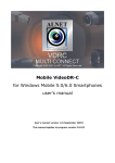
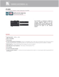
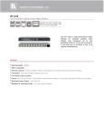
Instruction Manual of Sana fiber interferometer
Auto Non-contact Sana Fiber Interferometer
Instruction Manual
V.1
Shenzhen Dimension Technology Co., Ltd
2008.1
Shenzhen Dimension Technology Co., Ltd
1
Instruction Manual of Sana fiber interferometer
General Information
Sana fiber interferometer is independently developed by Dimension Technology with patent, used to
measure radius of curvature, Apex offset, Fiber Height and polishing angle,keyerror of APC connector, in
the meantime, show the topography of the connectors and fiber ends directly and clearly.
The main parts of Sana include interferometer, Lenovo table business computer and software package.
Sana adopt 650nm high power LED Light source, which ensure user get clear interference image.
Sana offers two kinds of chucks (2.5mm universal &1.25mm universal), with which user can test almost all
kinds of connecters. 2.5mm universal used to measure FC/PC.SC/PC.ST/PC, E2000/PC, DIN, FC/APC,
SC/APC kinds of connectors, 1.25mm universal used to measure LC/PC, MU/PC, LC/APC kinds of
connectors, and you don’t need to replace chucks and calibrate when you transfer between APC and PC
connector mesurement, only turning “angle adjuster” to relative angle is ok, very convenient to operate.
Our software has features of accuracy, high repeatability and convenient operability. Before initial test, user
should calibrate the unit first. It’s very easy to calibration for Sana. When landing calibration interface,
turning six points averagely and measuring after focusing accurately, then click “ok” button, it will be
automatically calibrated. You don’t need to move hard device by yourself, as the software will calibrate inner
settings automatically.
Then user can start measurement, only click “measure” button can finish one test, the test result and six
historical records will be shown right under the interface, user could decide to save the record or not. If yes
the data will be saved in excel format, and it will judge the result qualified or not automatically according to
user’s criteria or defaulted criteria. In the meantime, the topography of the fiber or connector will be shown
on the screen by 3D mesh diagram as well as contour diagram and surface roughness diagram.
Features
1 High repeatability, accuracy.
2 Convenient hardware and software operability.
Don’t need to change chucks when transfer between APC and PC connecter measurement.
When calibration, software will calibrate automatically, user don’t need to move the unit.
3 With patent, easily fasten chucks, Unique APC Fluctuate locate technology made the measurement never
more precisely.
4 3D-Mesh diagram and analysis chart directly reflect fiber or connecters details.
5 Test report and data will be saved in excel format, easy for document management and print out.
6 Absolutely competitive price.
Shenzhen Dimension Technology Co., Ltd
2
Instruction Manual of Sana fiber interferometer
Configuration and accessories
1 1x Interferometer
2 1x Lenovo table computer
3 2x chucks(LC universal and SC universal)
4 2x APC locator clamps(FC/APC ,SC/APC,)
5 2x calibration connectors +Standard Utensil
6 1x toolset
7 1x RS232 cable
8 1x power cable
9 1x software set
10 1x User manual
Shenzhen Dimension Technology Co., Ltd
3
Instruction Manual of Sana fiber interferometer
Parameters
Repeatability
Stability
Working Temperature
Zoom time
Resolution
Wavelength
Power supply
Dimension
Shenzhen Dimension Technology Co., Ltd
ROC
Fiber height
Apex offset
Angle
ROC
Fiber height
Apex offset
Angle
-10℃~30℃
10X
1um
650nm
12V
0.3mm
8nm
2um
0.02deg
0.5mm
12nm
5um
0.03deg
44cm*22.5cm*17.5cm(L * W * H)
4
Instruction Manual of Sana fiber interferometer
II Installation
2.1 Sana operation panel introduction
Sana hardware for usrer operate
three parts
2.1.1
includes: back panel, chucks worktable and mirror control hole
as shown on picture 5:
Picture 5 Chucks worktable
2.1.2
Sana Back Panel as shown on picture 6:
DC 12V power receptacle, data cable receptacle RS232, VIDEO Out receptacle VIDEO
OUT and on/off switch
Picture 6 Sana Back Panel
Shenzhen Dimension Technology Co., Ltd
5
Instruction Manual of Sana fiber interferometer
2.1.3
Mirror control hole as picture 7:
Picture 7 Sana Mirror control hole
2.2
Hardware assembly
Please take out the Sana interferometer onto firmness stage with power in “off” status, plug
data cable RS232 into RS232 receptaclel, the other terminal connect it with PC, plug 1394 data
cable into VIDEO OUT receptacle, the other terminal connect to capture card of PC, insert DC
12V into sana receptacle..
2.3
Software Installation
Insert USB key into USB receptacle of PC, follow below procedure:
2.3.1
2.3.2
2.3.3
Support Office 2003 installation, follow installation guide offered by Microsoft.
Matlab installation. There are three discs in Matlab, just install the first one is ok.
Capture card driver installation:
Install windows patch 《dotnetfx.exe》 and 《WindowsXP-KB885222-v2-x86-CHS.exe》
wich under folder 《poitgreycapture card driver》, then install PGRInstallBase.exe under
folder 《PointGrey》.
2.3.4
Dimension Sana interferometry software installation, click Dimension Sana software and
install as instructed.
2.3.5
After all software installation finshed please startup Matlab program first, then exit after
completness, then running Dimension Sana interferometry software.
2.4
Dimension Sana interferometry software interface.
Dimension Sana interferometry interface as shown on picture 8, which includes
main menu, live image, information setting parts and live report.
Shenzhen Dimension Technology Co., Ltd
6
Instruction Manual of Sana fiber interferometer
Picture 8 Dimension Sana interferometry interface
2.4.1 Setup
After running Dimension Sana interferometry software, setup by main menu or
hotkey “setup” .
Shenzhen Dimension Technology Co., Ltd
7
Instruction Manual of Sana fiber interferometer
The first item is company name.
The second item is calculation region, Fiber Dia means dia of the fiber connector to
be measured, the rest two are the calculation region, usually user don’t need to re-set them.
The defaulted setting for them are: Region(um):180,Region(um):140,AvgDia(um):
100.
The third item is measurement criteria setup, three criterias for selection, IEC,
Telicordia and user customized criteria, if customized, please save the criteria and next
time you may load it autumatically( the format of the file must be .ini)
The fourth item is “data save set“, measurement data and single measurement
report method and path setup could be setted in this item. “auto” “ask” and “off” three ways
for option. Attention:Date and report must save in a folder,not in harddisk root
directory.
2.4.2 Information setup as shown on picture 12.
Picture 12 information setup
Connector type: select relative fiber type to be measured.
Connector ID: two options, “auto Ine” means system will auto design connector ID by
increased number, “custom” is designed by user everytime before meansurement in “result”
item input connector ID as shown on picture 13
Picture 13
2.4.3 Hot keys as shown on picture14
Shenzhen Dimension Technology Co., Ltd
8
Instruction Manual of Sana fiber interferometer
picture14
How to use Sana interferometer
3.1
Chuck Setting
There are two chucks included, one is 2.5mm universal, the other one is 1.25mm
universal, 2.5mm universal truck used to meansure SC/UPC 、FC/UPC、ST/UPC、
E2000/UPC、DIN、SC/APC、FC/APC、E2000/APC connectors, 1.25mm universal chuck
is used to measure LC、MU connector.
1. How to set 2.5mm fiber connector
insert 2.5mm fiber connector into 2.5mm universal chuck and lock it by turning
connector locker, Make sure angle is in 0 degree by checking angle bar and the
moving base is locked, slightly turn the chuck to bottom right direction to make the
chuck closely in touch with horizontal adjuster and vertical adjuster as shown on
picture 15.
Attention: chuck station must be horizontal!
Picture 15
Shenzhen Dimension Technology Co., Ltd
9
Instruction Manual of Sana fiber interferometer
Turning focusing knob till get sharp image, then turning horizontal adjuster and
vertical adjuster till the image within live round circle, then lock chuck fastener.
1.25mm fiber conenction installation is the same way as 2.5mm fiber connector.
3.2 Calibration
Please re-calibrate in case of replacing chuck or big diffrence of figure “apex
offset”, insert calibration connector to chuck station and lock it fastenly, turning
focusing knob till get sharp interferometry image, click “calibrate” to get into
calibration interface, as shown on picture 16.
Please pay attention to following points when calibration:
1 set “Angel “ to 0 degree by truning “angle adjuster”.
2. the former part of “angle adjuster” must closely in touch with turning panel,
if no please unlock the turning panel locker first, set again till they are in
closely touch with each other then lock angel adjuster;
3. the chuck panel should be locked when Sana operating;
4. calibration connector should be locked when calibrating or measuring;
5. Turning 6 times to fulfill calibration, each time turning 60degree.
picture16
Calibration Procedure:
1. Insert alibrate connector,lock “chuck fastener” and turning “focusing knob” till get
the most sharp image;
2. Press “ measure” to fulfill the first test, then unlock fiber connector and turning 60
degree lock it again to measure the second time, measure six times in total by
this way.
3. The system will calculate the warp automatically, the warp of X axis will shown on
Shenzhen Dimension Technology Co., Ltd
10
Instruction Manual of Sana fiber interferometer
“X_Apexoff(um) “”,the warp of Y axis will shown on Y_Apexoff(um), if any of the
figure larger than 10um the system will remind user to turn the direction mirror as
shown on picture 17, after done please re-calibrate the system till the two figures
within 10um, press OK to save the calibration figure and date repaired as shown
on picture 18, if user don’t turn director mirror as picture 17, the system will repair
the warp automatically as well.
picture17
4. Press Ok as shown on picture 18 to save calibration data and exit calibration
interface.
picture18
3.3 Measurement: UPC fiber connector
User may start measurement after chuck installation and calibration, before
measurement please setup judgement criteria and data saving path.
3.3.1 Judgement criteria setup
User may setup criteria by main menu or hotkey”setup”, choose criteria in need
from IEC、telicordia or Custom, if you select custom, please input the figure and
press “save as” to save the data( the saved file format must in .ini)。
3.3.2 Data saving setup
Data saving includes,measurement data and single measurement report
method and path setup could be setted in this item. “auto” “ask” and “off” three ways
for option. Attention: Date and report must save in a folder,not in harddisk root
directory.
Data saving may carry out by main menu and hotkey”setup”, details as below:
Auto means auto save as defaulted; ask means if user want to save or not; off
means don’t save.
3.3.3 Image brightness setup
Click “Image” under main menu, right click “ Video set” to fulfill brightness setup.
3.3.4 Measurement-UPC fiber connector
User may start meansurement after finish all parameter setup, Before start
please make sure the fiber connector endface is clean(it will effect test result if not
Shenzhen Dimension Technology Co., Ltd
11
Instruction Manual of Sana fiber interferometer
clean) . insert fiber connector to sana chuck and lock it, turning focusing knob till
get sharp interferometry image, then click “ measurement” key or F12 directly to
start measurement.
Measurement result will be created at the bottom right of the interface as shown
on picture19, the worst figure will be shown in red color to remind user and the
system will judge the result pass or not automatically, the lastest six hostorical
records will be shown directly under the interferometry interface.as shown on
picture 20.
picture 19
picture 20
3.4
APC connector meansurement
When measuring APC fiber conenctor user don’t need to replace chuck or
re-calibrate, just unlock “turning base locker” and turn “ angle adjuster” to 8 degree,
then lock the turning base, insert APC locator clamp into chuck groove.
After insert fiber connector please turn focusing knob till get sharp image, if the
fiber image out of live round circle more then 1/3 user need to just the chuck position
to turn it in circle . ( the chuck station should in horizontal).
Attention: choose “APC” connector type in information setup interface.
Shenzhen Dimension Technology Co., Ltd
12
Instruction Manual of Sana fiber interferometer
Care and Maintenance
4.1
Care and maintenance
1.Keep Sana free from severe sources of vibration. Do not place the unit where it is
vulnerableto be knocked or physically damaged,
2.Turning 60 degree each time when calibration, and focusing live image accuratelly;
3. Fiber connector endface must be clean.;
4. If it’s very tight when insert fiber connector please check if glue or same kinds of
dirty stick on fiber ferrule.
4.2 Please contact Dimension Technology if any after-service problem.
Shenzhen Dimension Technology Co., Ltd
13