Download Bed-Check® Model Vr Bed-Check® Sensormat® User Manual
Transcript
Bed-Check® Model Vr
Bed-Check® Sensormat®
An Outcome Based System
User Manual
0163-440-A
Reducing the Risk of Falls Through Innovative Technology Since 1978
2
Table of Contents
How The Bed-Check® System Can Work For You ................................................2
Programmed/Inputted Operating Characteristics..................................... 2
Printable Outcome-Based Information.................................................. 2
Patient’s Information................................................................................ 3
Exportable Outcome-Based Information of Last 24 Alarms
for Database/Spreadsheet Analysis..............................................3
Reset Information..................................................................................... 3
Information Subject to Output to Printed Report or Computer File...........3
How To Use the System ........................................................................................ 4
(Complete detailed instructions)
Sensormat®............................................................................................... 4
Control Unit ............................................................................................. 6
Manual Programming Guide................................................................................. 9
Programming Procedure ..................................................................................... 11
Nurse Call Installation Instructions.................................................................... 13
Care and Maintenance ........................................................................................ 14
Interfacing with the Nurse Call System................................................................14
Troubleshooting .................................................................................................. 15
Warranty Information ........................................................................................ 17
How The Bed-Check® (Outcome Based)
System Can Work For You
Introduction
The Bed-Check® Model Vr Control Unit’s functions are accessible and programmable through a laptop or personal computer. The listings below describe the
programmable functions of the Control Unit and the accessible statistics maintained by the Control Unit. You may refer to the Model Vr ACCESS Program’s
manual (CD) for further information.
Programmed/Inputted Operating Characteristics
• Setup the Printer Port.
• Limit the external ability to set the Alarm Delay time in seconds to a
range of 1 to 3 seconds versus a normal range of 1 to 9 seconds.
(Reducing Alarm Delay can restrict manual programming functions.)
• Input Patient ID.
• Audible Reset Alarm can be enabled or disabled.
• Nurse call system - normally open or closed.
• Select the Tone Option and change the type of alarm sound to the one
best suited for the patient.
• Select the Relay Action - type of electrical impulse needed by the nurse
call system.
• Select the Hold Time in seconds before MONitoring begins, from 1 to 20
seconds.
• Alarm Delay time in seconds, from 1 to 9 seconds.
• Volume of the alarm.
• Define the Control Unit’s operating Default settings for all of the above.
• Input the last Bio-Med Date of service.
Printable Outcome-Based Information
Unit Information:
• All of the above operating characteristics.
• Unit serial number and manufactured date.
• Total cumulative time the unit has been in service since inception.
• Date of the last Repair/Maintenance Authorization (RMA) and number by
Bed-Check®.
• The last date the control unit was serviced by Bio-Med.
2
Patient’s Information:
• Patient’s ID.
• Cumulative time the unit has been in service with the particular patient.
• The response times for the last twenty-four alarms.
• The average response time for the last four alarms.
• The last response time.
• Time and date of the last twenty-four alarms, and response times to the
alarms.
Exportable Outcome-Based Information of Last 24 Alarms for Database/
Spreadsheet Analysis
• The exported file name will default to the patient ID.
• Date of each alarm.
• Time of each alarm.
• Response time to each alarm.
Reset Information
• Reset the patient information to erase all.
Information Subject to Output to Printed Report or Computer File
• Information that is depicted on the screen can be sent to the printer for
assimilation with patient files or management reports;
• Information that is depicted on the screen can be sent to a text (*.txt) file
for later printing or export to a word processing program; and,
• Alarm history can be exported to a comma delimited file that can be
imported into a spreadsheet (database) program.
Alternatively, the control unit can be put into service as it is shipped to you. You
may choose to disregard and not utilize the programmable/printable features of
the control unit.
The control unit’s factory default settings are:
1) The tone option is set to a medium beep
2) The nurse call relay action is set to a normally open system
3) The hold delay time is set to 5 seconds
4) The alarm delay time is set to 3 seconds.
Bed-Check® will pre-set optional settings at the factory if requested at the
time the order is placed. Contact your Distributor for more details.
For Manual Programming Please Refer to the Model Vr Program Guide (CD)
and Appendix G therein or the section entitled Manual Programming Guide on
page 9 of this manual.
3
How To Use The System
The Bed-Check® system consists of a control unit, a power supply and a disposable pressure-sensitive Sensormat®, available in two sizes for use on either a
standard hospital bed or a bed-side chair.
When the patient’s weight on the Sensormat® ceases for a pre-selected number
of seconds, the control unit activates two alarms (if selected): a call signal at the
nursing station and an audible alarm in the patient’s room. The nurse, having
been alerted that a patient is attempting to exit the bed, can counsel the patient
by intercom (if available), and simultaneously send immediate assistance.
Sensormat®
To ensure effectiveness, place the Sensormat® across the width of the bed, ON
TOP OF THE MATTRESS. The preferred Sensormat® location is directly under
the patient’s buttocks three to five inches below the bend in the mattress when
the head of the bed is elevated. Effective operation of the Sensormat® in the
alternative location, behind the patient’s back, is dependent upon their weight
and the articulation angle of the bed.
Note: Nursing personnel should test the system’s effectiveness daily when either
Sensormat® position is selected. Sensormats® may not be effective with air bed
type mattresses, test before using.
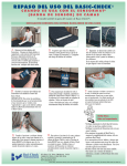
Important: Use of Rubber Bands and clips keeps Mat in
To prevent slipping and to maintain
position and aids in serviceability
the correct position of the Sensormat®,
always use the enclosed rubber bands
and metal clips.
A. Thread one end of the band through
the hole of the clip to form a loop. Pass the other
end of the band through the loop and pull tight to
form a knot at the base of the clip.
B. Thread the other end of the band through the
Sensormat® hole to form a loop. Bring the lip
through the loop and pull tight to form another knot
at the end of the Sensormat®. Repeat these steps on
the other end of the mat.
C. Position Sensormat® across width of bed 3 inches to 5 inches below bend in
mattress so it will be under the patient’s buttocks.
D. Attach the clips to the piping at the bottom of the mattress on both sides of
the bed or to the bed frame. The idea is to have the rubber bands taut so the
Sensormat® does not slide back and forth over the mattress.
E. You may place over the Sensormat® a felt or incontinence pad, towel, draw
sheet, rubber sheet, sheep skin or convoluted foam pad. Make the bed as usual.
4
To ensure compatibility, the Model Vr control unit should be used only with
Bed-Check® Sensormat® pressure sensitive mats. An alarm may sound when a
damaged or incompatible mat is plugged into the control unit. The power supply must be unplugged from the unit or from the wall to cancel the alarm.
Always physically inspect the status of the control unit by viewing the illuminated indicators on the face of the control unit before leaving the patients
room. If the control unit is in either HOLD mode, press the reset button to
immediately begin monitoring and ensure the green monitor light is flashing.
There is a possibility of the patient exiting the bed or chair during either HOLD
period.
The Sensormat® is effective for patients weighing 100 pounds or more. For
patients weighing under 100 pounds, test the effectiveness immediately upon
installation with the patient in bed. Please be aware that the physiology of each
patient is different. The functionality of the Sensormat® is impacted by the
physics of the patient’s weight and height.
Plug the Sensormat® cord connector into the side of the control unit (Port designated “Sensormat®”). Sensormats® are available with 5 1/2 foot and 8 foot cords.
If you are using the wire holster with control unit, 5 1/2 foot cords work best.
Other cord lengths may be special ordered.
Nursing personnel should test the system daily for proper functioning. If the
patient weighs 100 pounds or more, the nurse may test the system using just
hand pressure on the Sensormat®. Lighter weights could possibly compromise
system performance, and if the patient weighs less than 100 pounds, system
function should be checked using the actual patient’s presence in the bed. If the
system does not perform properly, trying a different Sensormat® may resolve the
problem.
5
Control Unit
Operation
The Bed-Check® Model Vr control unit provides the following indicators and
functions:
HOLD - The yellow HOLD indicator is illuminated when the control unit is on
and waiting to begin monitoring. When the HOLD indicator flashes, it indicates
that there is weight on the Sensormat® and the Control unit will begin
MONitoring after the preselected HOLD delay countdown. The HOLD delay
countdown may be set from 1 to 20 seconds. We recommend 5 seconds.
There is a separate and distinct temporary 25 second hold time programmed into
the Control Unit. When weight is on the Sensormat® (patient on the mat in bed
or on the chair) and the Control Unit is MONitoring (green light), the caregiver
may press the RESET button to put the system into temporary HOLD status
(blinking yellow light) for servicing the patient. The unit will remain in this
temporary HOLD status as long as weight stays on the Sensormat® for up to 25
seconds, and then will resume MONitoring. However, if any time during the 25
seconds weight is removed from the Sensormat®, this immediately puts the unit
into permanent HOLD (steady yellow light). Once on permanent HOLD, the
unit will begin the preselected HOLD delay countdown (e.g. 5 seconds) to
MONitor only when weight is returned to the Sensormat®.
Note that in any HOLD mode, monitoring may be started immediately (no
delay countdown) by pressing RESET, as long as weight is on the Sensormat®.
Always assure the green MONitor light is on before leaving the patient.
The caregiver may adjust the patient/resident in bed, do local therapy, etc. during the (25 second) temporary HOLD period without setting off the alarm. If
the Control Unit begins to again monitor and it is taking longer to care for or
remove the patient/resident from the bed, press RESET again to renew the 25
second temporary HOLD time. If the care giver has completed the task and the
control unit is still in the temporary (blinking) HOLD status, press RESET to
immediately begin MONitoring before leaving the room.
MONitor - The green MON indicator is illuminated when the control unit is
monitoring the patient. If the patient’s weight is off the Sensormat® for the entire
preselected delay, i.e. 3 seconds, the alarm will sound. If RESET is pressed
while the MON indicator is active, the control unit will return to the HOLD
mode. Please review the HOLD function above. A flashing MONitor indicator
indicates that the unit is actively monitoring and that weight is off the
Sensormat®, but the preselected alarm delay has not yet expired.
6
ALARM - The red ALARM indicator is illuminated when the control unit is
alarming. The control unit will exit the alarm mode and enter the HOLD mode
when the RESET button is pressed. The alarm delay time can be set within a
range of 1 to 9 seconds. We recommend 3 seconds. The time delay should be set
just long enough to allow patient movement in bed without generating false
alarms.
The nurse call system must be physically reset in the patient’s room after resetting the Control Unit in the event of an alarm.
RESET - This button is used to change the operating mode of the Control Unit.
If the unit is in the MONitoring mode (weight is on the Sensormat®), pressing
the RESET button will cause the Control Unit to enter a blinking HOLD (interim wait status) for 25 seconds. If weight is removed from the Sensormat® during
the blinking HOLD, the Control Unit will begin a fixed HOLD status. If the
unit is alarming, the RESET button will change the operating mode to the
HOLD mode.
▲ - The up arrow on the face of the Control Unit will increment the delay time
by one second each time it is pressed. If the delay is set to nine seconds, pressing the up arrow will change the delay to one second. This button is active during the HOLD mode and MON mode. The up arrow is inactive while the unit is
alarming. The Control Unit can be internally set to limit the external cycling of
the alarm delay to within a range of 1 to 3 seconds (please review the Model Vr
Program Guide).
Always press the RESET button to immediately begin monitoring before
leaving the patient.
Placement of the Control Unit
Using the nylon Velcro® strap or optional holster, hang the Control Unit on the
bed in a place that is out of the patient’s reach and sight, but where it is readily
accessible to the nursing personnel. Avoid unit placement in any area where it
might come in contact with bodily fluids. If the patient can reach the Control
Unit without moving off of the Sensormat®, relocate the Control Unit. The
Control Unit, alternatively, can be placed in a Bed-Check® wire holster for
placement on the back of the bed’s headboard.
7
Always physically inspect the status of the control unit by viewing the illuminated indicators on the face of the control unit before leaving the patient’s
room. If the control unit is in either HOLD mode, press the reset button to
immediately begin monitoring and ensure the green monitor light is flashing.
There is a possibility of the patient exiting the bed or chair during either HOLD
period without causing the system to alarm.
Plug the Control Unit’s external power supply cord into the Control Unit (Port
designated as "Power") first. Then plug the power supply into an AC wall outlet.
IF THE SENSORMAT® IS PLUGGED IN AND WEIGHT IS APPLIED TO
THE SENSORMAT®, THE CONTROL UNIT WILL ALARM IF THE NURSE
CALL CORD IS NOT PLUGGED INTO THE UNIT WHEN POWER IS SUPPLIED. The Control Unit will ignore the absence or presence of the nurse call
cord if the Relay Action is set to "no pullout protection". (Refer to the section
entitled Manual Programming Guide on page 9 for more information.)
Connect the Control Unit’s nurse call cord (phone style plug end) to the Control
Unit (Port designated as "Nurse Call"). Plug the 1/4 inch phono style plug into
the nurse call system. Some systems may require an adapter which may be purchased with your Bed-Check® System (For Details see the section entitled
Interfacing the Bed-Check® System with Your Nurse Call System on page 14).
The Control Unit and cords must be placed in such a location or manner in
which it would not subject them to damage from moving bed parts or
positioning of the bed. Do not position either component of the system such
that it may cause one to pull against the other, causing stress to the connecting wire or its connecting plug.
Once the patient is positioned properly on the Sensormat®, the yellow HOLD
indicator will begin to flash. After a preset monitoring delay (the delay time is
factory preset to 5 seconds) the Control Unit will begin monitoring automatically as indicated by the green MONitoring indicator. To bypass this delay, press
the RESET button and immediate monitoring will be indicated by the green
MONitoring indicator.
The Bed-Check® Control Unit, its power supply and the Bed-Check® Sensormat®
have been tested and listed by a Nationally Recognized Testing Laboratory as a
system, and have met all applicable FDA regulations. The Bed-Check® system is
categorized as Nurse Call Accessory Equipment and is tested to UL® Standard
1069 by Edison Testing Labs (ETL), and CSA® 22.2 No. 205R.
8
Manual Programming Guide
Introduction
The Bed-Check® Model Vr offers a variety of features that may be manually
programmed. The configuration information is retained in nonvolatile memory
within the control unit. The configuration can be changed at any time. The nonvolatile memory is also used to retain statistical data. This data may be accessed
using a laptop or desktop computer and special software available from
Bed-Check®.
Two methods are available for configuring the Model Vr:
1. Programming through the front panel of the Control Unit; and,
2. Programming with a personal computer.
Manual programming should only be performed when this manual is readily
available as a guide.
Manually Programmable Features
There are five user selectable features, each offering several options:
1. Alarm sound characteristic;
2. Nurse call system relay action - the type of electrical impulse required
by the nurse call system;
3. Hold delay - time in seconds that elapses before MONitoring occurs;
4. Alarm delay - time in seconds that elapses from the moment the patient’s
weight is off the Sensormat® to the moment of an alarm; and,
5. Alarm volume
The alarm sound is selected from a list of seven possible options. This allows a
facility to choose a sound which is distinctive from other equipment in use
around the patient, to use particular sounds to prioritize patients relative to a
particular patient’s risk for fall or to avoid becoming tone deaf to a particular
alarm by changing the tone periodically.
9
The Control Unit is shipped from the factory to operate with a normally open
nurse call system. This is appropriate for the majority of nurse call systems. The
Control Unit may be programmed to operate with a normally closed nurse call
system using a personal computer. A particular nurse call system, whether normally open or normally closed, will require either a continuous pulse, a single
pulse or repeated pulses to activate the nurse call system. The relay action
option allows the Control Unit to be adapted to the particular nurse call installation. In addition, the “no pull-out protection" option may be selected if the
Control Unit will not be plugged into a nurse call system. An alarm will also
sound if there is a bad connection between the nurse call cord and the Control
Unit.
The HOLD delay is factory preset to five seconds. The HOLD delay is the
period of time that elapses from the moment that the patient’s weight is placed
upon the Sensormat® and when the Control Unit automatically begins the
MONitoring mode. Although five seconds will suffice for most facilities, there
may be patients for which a different HOLD delay will work better, i.e. a particularly active patient may need a shorter delay while a patient who requires a
lot of adjusting while being placed in bed may require a longer HOLD delay
time. It is good practice to always press RESET when leaving the patient and
not depend on the automatic MONitoring function.
The alarm volume may be adjusted to balance the needs of alerting the staff to a
patient out of bed against the needs of nearby patients who may be affected by
the alarm. The volume may be adjusted from zero to nine when programming
through the front panel or zero to 31 when programmed via a personal computer. In either case, zero silences the alarm. A nine programmed from the front
panel will yield the same volume as a 31 programmed from a personal computer. The only difference in the two methods is the granularity (resolution) available in arriving at or near an intermediate volume level.
Programming Through The Front Panel
Programming the Model Vr Control Unit through the front panel should not be
attempted until this entire section has been reviewed and you feel comfortable
giving it a try. Programming of the Model Vr Control Unit through the front
panel is not possible if the “3 second limit” delay option is active. This option
must be disabled, using the programming with a personal computer option,
before programming through the front panel is possible. To (re)program any
individual feature you must begin at the beginning of the programming process;
all of the steps for the entire programming process must be followed.
10
Programming Procedure
Front panel of the Bed-Check® Model Vr Control Unit
Apply power to the Control Unit. It is not necessary to connect the nurse
call cord or to connect a Sensormat®.
1. Use the up arrow button
display to nine seconds.
on the face of the Control Unit to set the digital
2. Unplug the power supply from the Control Unit for several seconds.
3. While pressing the RESET button on the front panel, apply power to the
Control Unit. Release the RESET button after all indicator lights on the
right side of the front panel come on, and the unit beeps.
Note: All three indicator lights (ALARM, MONitoring, HOLD) should be
lit at this time. If not, start over with step one.
4. You are ready to program the sound option. If you do not wish to change
the sound, press RESET to skip this step and go to Step 5. To make a
change: The numeric display on the left side of the front panel shows the
current sound selection. Match the numeric display with the list below. Use
the up arrow buttons
to change the number displayed and choose the
desired sound from the list below. Once the appropriate number is displayed,
press the RESET button, a beep will follow.
11
Sounds:
0. Fast Beep
1. Medium Beep
2. Slow Beep
3. Ring
4. Warble
5. Triple Tone
6. Music
The ALARM indicator should go out leaving the MONitoring and HOLD
indicators lit.
5. If you do not want to change the relay action, press RESET to skip this step
and go to Step 6. To set the appropriate relay action, use the up arrow button
on the front panel, select the number for the desired relay action from
the list below. Press RESET when the correct number is displayed, a beep
will follow.
Relay Option:
0. Continuous closure
1. Repeated pulses
2. One Shot
3. No pull-out protection (do not use/or no nurse call system)
The MONitoring indicator should go out and the ALARM and HOLD indicators should remain lit.
6. If you do not want to change the HOLD time, press RESET to skip this step
and go to Step 7. Use the up arrow
to select the desired HOLD time.
The HOLD time is adjustable from 1 to 9 seconds. Programming through a
PC provides from 1 to 20 seconds HOLD time. This is the time in seconds
that will elapse before the unit will automatically begin MONitoring. After
selecting the desired HOLD time, press RESET, a beep will follow.
The HOLD indicator should go out and the ALARM and MONitoring indicators should remain lit.
12
7. If you do not wish to change the volume, press RESET to skip this step and
go to Step 8. Use the up arrow button
to set the desired volume. The
volume may be adjusted from zero to nine when programming through the
front panel or zero to 31 when programmed via a personal computer. In
either case, zero silences the alarm. A nine programmed from the front
panel will yield the same volume as a 31 programmed from a personal
computer.
If you have adjusted the volume, press RESET, a beep will follow.
8. Unplug the power supply from the unit for approx. 2 seconds.
9. Apply power to the control unit.
This ends the programming mode.
10. Adjust the delay using the arrow button
to an appropriate seconds
value, typically three seconds. This is the time that will elapse from the
moment that the patient’s weight leaves the Sensormat and the alarm
sounds. The range of options is 1 to 9 seconds.
This unit is now programmed.
Nurse Call Installation Instructions
The Bed-Check® Vr with Accessory Port performs the same functions as the
standard Vr monitor, but does have a significant advantage for facilities with
1/4” input jacks.
The facility’s existing Nurse Call cord is plugged directly into the Bed-Check®
Vr monitor via the port in the bottom center of the monitor as shown below. The
Bed-Check® Nurse Call cord, supplied with the unit, will then plug directly into
the existing Nurse Call port and into the port designated “Nurse Call” on the
unit. Always check the system before exiting the room.
The advantage of the unit is the elimination of an adaptor. Not hanging the
adaptor and extra power cord saves
space, possible confusion of connections, and the addition of basic adaptors that may be lost or damaged over
time. The Nurse Call system may be
utilized by the patient as is normally
done, and should the patient move off
the Sensormat®, the alarm will sound
at the nurses station as is normal.
Model Vr plugs into Nurse Call system
13
Care and Maintenance
The Bed-Check® Control Unit may not be effective with another manufacturer’s
sensing device, the use of which may cause damage to the Bed-Check®
Control Unit and will void the Bed-Check® warranty.
Danger of electrical shock. Never immerse the power supply or Control Unit in
any liquid.
If maintenance or opening of the Control Unit is required, it should be performed in a static-controlled (free) environment by qualified personnel.
The Control Unit and the Sensormat may be cleaned with a damp cloth or
sponge using mild disinfectants. Never use alcohol, acidic or harsh petroleum
based cleaners. If absolutely essential, the Control Unit may be gas sterilized up
to 120o F.
Interfacing with the Nurse Call System
The Bed-Check® Model Vr can be set for a normally open or normally closed
nurse call system. The unit is factory preset to function with a normally open
system. Please refer to the program manual.
The Control Unit uses a standard, two conductor, 1/4 inch phone plug, the most
common type of nurse call connection. If your nurse call system does not
provide a compatible input, contact Bed-Check® or your biomedical department
to obtain the appropriate adapter.
If your facility does not have a biomedical department, please contact
Bed-Check® at 1-800-523-7956. If requesting information on interfacing the
Control Unit to a nurse call system, please have the following information
available:
• The brand of your nurse call system.
• A description of the system’s call cord or pillow speaker, including the
type of plug and number of pins in the plug.
• Whether your nurse call system is normally open or normally closed.
14
Troubleshooting
Test the system’s operations daily. Failure to do so could result in injury or
death.
Problem: No alarm - Patient out of bed
Check:
1. Are you using the Bed-Check® Sensormat® or another manufacturer’s
mat? A foreign mat will generally cause the Control Unit to alarm when
it is plugged into the unit and power is on.
2. Did the patient get up during the preset HOLD period?
3. Is the Sensormat® bent through misplacement or handling? Is it
functional - try another Sensormat®.
4. Is there an object putting pressure on the Sensormat® simulating the
patient’s weight?
5. Is there power to the unit?
Problem: Control Unit alarms during set up
Check:
1. Is the connector between the Sensormat® and Control Unit snapped in
properly?
2. Has the cord been pulled from the Sensormat® or its connector?
3. Is the mat a Bed-Check® Sensormat®?
4. If the unit is programmed for a nurse call cord (pull out protected), verify
that the cord is plugged into the unit.
Problem: Alarm triggered - Patient in bed
Check:
1. Is the Control Unit programmed to send a signal to the nurse call system
and the nurse call cord is not plugged into the Control Unit?
2. Is the Sensormat® placed beneath the patient’s buttocks, or if used behind
the back, is the patient of sufficient weight and the bed properly
adjusted?
3. Has the Sensormat® slipped toward the end of the bed because the
rubber bands and clips were not used to secure the Sensormat® into
position beneath the patient’s buttocks?
4. Is the connector between the Sensormat® and Control Unit snapped in
properly?
5. Is the time delay set too low for the patient’s level of activity?
15
6. If the patient weighs less than 100 pounds, has the system been tested
with that patient?
7. Did the patient get up and return to bed upon hearing the alarm?
8. Has the Sensormat® cord been pulled out or damaged (check moving bed
parts)?
Problem: Room alarm triggered - No call at nursing station
-orNurse call will not turn off after an alarm
Check:
1. Is the nurse call plug firmly connected to the patient station or adapter?
2. Is the call cord or pillow speaker firmly connected to the patient station
or adapter?
3. Is the adapter firmly connected to the patient station?
4. Was the Control Unit reset after an alarm before the nurse call system
alarm was canceled?
5. Is the Control Unit programmed to have “No Pull Out Protection"? If
so, a signal will not be sent to the nurse call system.
6. Has the nurse call adapter been tested for proper functioning?
7. Is the mat a Bed-Check® Sensormat®?
16
LIMITED WARRANTY:
BED-CHECK® CONTROL UNITS
1. WARRANTOR:
This Limited Warranty is given by Bed-Check®, 1620 N 20th Cir, Lincoln, NE 68503.
2. DURATION:
This Limited Warranty begins on the date the product is delivered to the purchaser and continues for
a period of two years (new units) or one year (refurbished units).
3. TO WHOM THIS LIMITED WARRANTY IS GIVEN:
This Limited Warranty is given to the original purchaser of Bed-Check’s® products only.
4. PRODUCTS COVERED:
This Limited Warranty covers all Bed-Check® Control Units. (i.e. Model Vr, Classic-Check, ChairCheck II, and Basic-Check)
5. WHAT IS COVERED UNDER THIS LIMITED WARRANTY:
Defects in material and workmanship which occur within the defined duration of this limited warranty.
Warrantor makes no other warranties expressed or implied, including without limitation, warrantor
makes no warranty as to merchantability or fitness for a particular purpose.
6. WHAT IS NOT COVERED UNDER THIS LIMITED WARRANTY:
a) ANY INCIDENTAL, INDIRECT, OR CONSEQUENTIAL LOSS, DAMAGE, OR EXPENSE
THAT MAY RESULT FROM ANY DEFECT, FAILURE, OR MALFUNCTION OF THE CONTROL
UNITS.
b) ANY INCIDENTAL, INDIRECT, OR CONSEQUENTIAL LOSS, DAMAGE, OR EXPENSE
THAT MAY RESULT FROM USE OF THE CONTROL UNITS WITH ANOTHER MANUFACTURER’S
PRESSURE SENSITIVE MAT, SENSING DEVICE, OR OTHER FALL PREVENTION
PRODUCT.
NOTE: SOME STATES DO NOT ALLOW THE EXCLUSION OR LIMITATION OF INCIDENTAL
OR CONSEQUENTIAL DAMAGES, SO THE ABOVE LIMITATIONS OR
EXCLUSIONS MAY NOT APPLY TO YOU.
c) Any defects or damage to the Control Units that may result from use of the Control Units with
another manufacturer’s parts, pressure sensitive mat, sensing device, or other fall prevention product.
d) Any failure that results from an accident, purchaser’s abuse, neglect or failure to operate the Control
Units in accordance with the instructions provided in the owner’s manual(s) supplied with the
Control Units.
e) Any Control Units which have the serial numbers altered, defaced or removed.
f) Any Control Units which have been altered or modified in any way without the express written consent
of Bed-Check®.
g) Any Control Units which have been repaired other than by Bed-Check®.
7. RESPONSIBILITIES OF WARRANTOR UNDER THIS LIMITED WARRANTY: a) In the
event of a defect, malfunction, or other failure of the product not caused by any misuse or damage
to the product while in the possession of purchaser, the warrantor will remedy the failure or defect
without charge to the purchaser within a reasonable time. The remedy will consist of repair or
replacement of the product, or refund of the purchase price, at the warrantor’s option. If the product
is no longer available, warrantor will supply purchaser with a comparable product or refund the purchase
price at warrantor’s option. However, the warrantor will not elect refund unless it is unable to
provide replacement, and repair is not commercially practicable and cannot be made within a reasonable
time, or unless the purchaser is willing to accept such refund. b) If this product or one of its
component parts contains a defect or malfunction, after a reasonable number of attempts by the warrantor
to remedy the defects or malfunctions, the purchaser will be entitled to either a refund or
replacement of the product or its component part or parts. Replacement of a component part
includes its free installation.
8. RESPONSIBILITIES OF THE PURCHASER UNDER THIS LIMITED WARRANTY:
a) Disinfect the Control Unit, if necessary, so that it is reasonably free from infectious matter.
b) Package the Control Unit with a minimum of two inches of shock absorbent packaging material.
Deliver or ship the Control Unit to Bed-Check®. Freight costs, if any, must be borne by
the purchaser.
c) Use the Control Unit with reasonable care and in accordance with the supplied owner’s manual.
THIS LIMITED WARRANTY GIVES YOU SPECIFIC LEGAL RIGHTS AND YOU MAY
ALSO HAVE OTHER RIGHTS WHICH VARY FROM STATE TO STATE.
17
LIMITED WARRANTY
BED-CHECK® SENSORMATS®
1. WARRANTOR:
This Limited Warranty is given by Bed-Check®, 1620 N 20th Cir, Lincoln, NE 68503.
2. DURATION:
This Limited Warranty begins on the date the product is delivered to the purchaser and continues for a period of
one year or for the duration of the warranty stated on the Sensormat® label from the date first installed, whichever
comes first.
3. TO WHOM THIS LIMITED WARRANTY IS GIVEN:
This Limited Warranty is given to the original purchaser of Bed-Check’s ® products only.
4. PRODUCTS COVERED:
This Limited Warranty covers all Bed-Check® Sensormats®.
5. WHAT IS COVERED UNDER THIS LIMITED WARRANTY:
Defects in material and workmanship which occur within the period described in paragraph 2. Warrantor makes
no other warranties expressed or implied, including without limitation, warrantor makes no warranty as to merchantability or fitness for a particular purpose.
6. WHAT IS NOT COVERED UNDER THIS LIMITED WARRANTY:
a) ANY INCIDENTAL, INDIRECT, OR CONSEQUENTIAL LOSS, DAMAGE, OR EXPENSE THAT MAY
RESULT FROM ANY DEFECT, FAILURE, OR MALFUNCTION OF THE SENSORMAT® ANY INCIDENTAL, INDIRECT, OR CONSEQUENTIAL LOSS, DAMAGE, OR EXPENSE THAT MAY RESULT FROM
USE OF THE SENSORMAT® WITH ANOTHER MANUFACTURER’S CONTROL UNIT OR OTHER FALL
PREVENTION PRODUCT.
NOTE: SOME STATES DO NOT ALLOW THE EXCLUSION OR LIMITATION OF INCIDENTAL OR
CONSEQUENTIAL DAMAGES, SO THE ABOVE LIMITATIONS OR EXCLUSIONS MAY NOT
APPLY TO YOU.
b) Any defects or damage to the Sensormat® that may result from use of the Sensormat® with another
manufacturer’s parts, control unit, or other fall prevention product.
c) Any failure that results from an accident, purchaser’s abuse, neglect or failure to operate the Sensormat® in
accordance with the instructions provided on the Sensormat® label.
d) Any Sensormat® which has the serial numbers altered, defaced or removed.
e) Any Sensormat® which has been altered or modified in any way without the express written consent of
Bed-Check®.
f) Any Sensormat® which has been repaired other than by Bed-Check®.
7. RESPONSIBILITIES OF WARRANTOR UNDER THIS LIMITED WARRANTY:
a) In the event of a defect, malfunction, or other failure of the product not caused by any misuse or damage to the
product while in the possession of purchaser, the warrantor will remedy the failure or defect without charge to
the purchaser within a reasonable time. The remedy will consist of repair or replacement of the product, or
refund of the purchase price, at the warrantor’s option. If the product is no longer available, warrantor will supply
purchaser with a comparable product or refund the purchase price at warrantor’s option. However, the warrantor
will not elect refund unless it is unable to provide replacement, and repair is not commercially practicable and
cannot be made within a reasonable time, or unless the purchaser is willing to accept such refund.
b) If this product or one of its component parts contains a defect or malfunction, after a reasonable number of
attempts by the warrantor to remedy the defects or malfunctions, the purchaser will be entitled to either a refund
or replacement of the product or its component part or parts. Replacement of a component part includes its free
installation.
8. RESPONSIBILITIES OF THE PURCHASER UNDER THIS LIMITED WARRANTY:
a) Disinfect the Sensormat®, if necessary, so that it is reasonably free from infectious matter.
b) Package the Sensormat® unfolded and in a flat position. Deliver or ship the Sensormat® to
Bed-Check®. Freight costs, if any, must be borne by the purchaser.
c) Use the Sensormat® with reasonable care and in accordance with the supplied owner’s manual.
THIS LIMITED WARRANTY GIVES YOU SPECIFIC LEGAL RIGHTS AND YOU MAY ALSO HAVE
OTHER RIGHTS WHICH VARY FROM STATE TO STATE.
18
This monitor may not be compatible with mats manufactured by companies other
than Bed-Check®. Use of incompatible mats may result in injury or death, and
voids the product warranty.
Important Notice
Date and Time Retention on the Vr During Extended Shelf Storage
In a continuing effort to increase product reliability, Bed-Check® has included a state of
the art memory backup system intended to last the life of the product. The system
avoids the problems associated with battery failure and leakage by utilizing a high value
electrolytic capacitor as a power source. This capacitor is maintenance free but does
require system power input every 30 to 60 days to maintain the “Date & Time” data.
The recommended recharge time is 2.5 hours for a full charge. If this information is lost
however, the unit will automatically reload the information from the host PC during set
up for the next patient. This is an automatic, transparent function and requires no user
input to ensure that the information has been fully updated.
Mailing Address: PO Box 80238, Lincoln, NE 68501-0238
Shipping Address: 1620 N 20th Cir Lincoln, NE 68503-1103
1-800-523-7956
www.bedcheck.com
© 2008 The Stanley Works All Rights Reserved
Velcro is a registered trademark of 3M.
Bed-Check, Chair-Check, Sensormat and Access are registered trademarks of Stanley Logistics, Inc.
20


