1
Cat. No. H100-E1-04A
E5CN
Temperature Controller
USER’S MANUAL
E5CN Temperature Controller
User’s Manual
Revised July 2003
iv
Notice:
OMRON products are manufactured for use according to proper procedures by a qualified operator
and only for the purposes described in this manual.
The following conventions are used to indicate and classify precautions in this manual. Always heed
the information provided with them. Failure to heed precautions can result in injury to people or damage to property.
!DANGER
Indicates an imminently hazardous situation which, if not avoided, will result in death or
serious injury.
!WARNING
Indicates a potentially hazardous situation which, if not avoided, could result in death or
serious injury.
!Caution
Indicates a potentially hazardous situation which, if not avoided, may result in minor or
moderate injury, or property damage.
Visual Aids
The following headings appear in the left column of the manual to help you locate different types of
information.
Note Indicates information of particular interest for efficient and convenient operation of the product.
1,2,3...
1. Indicates lists of one sort or another, such as procedures, checklists, etc.
v
Conventions Used in This Manual
Meanings of Abbreviations
The following abbreviations are used in parameter names, figures and in text explanations. These
abbreviations mean the following:
Symbol
PV
Term
Process value
SP
AT
Set point
Auto-tuning
ST
EU
Self-tuning
Engineering unit (See note.)
Note “EU” stands for Engineering Unit. EU is used as the minimum unit for engineering units such as °C, m, and g.
The size of EU varies according to the input type. For example, when the input
temperature setting range is –200 to +1300°C, 1 EU is 1°C, and when the
input temperature setting range is –20.0 to +500.0°C, 1 EU is 0.1°C.
In the case of analog input, the size of EU varies according to the decimal
point position of the scaling setting, and 1 EU becomes the minimum scaling
unit.
How to Read Display Symbols
The following tables show the correspondence between the symbols displayed on the displays and
alphabet characters.
A B C D E F GH I J K L M
N O P Q R S T U V WX Y Z
OMRON, 1998
All rights reserved. No part of this publication may be reproduced, stored in a retrieval system, or transmitted, in any form, or
by any means, mechanical, electronic, photocopying, recording, or otherwise, without the prior written permission of
OMRON.
No patent liability is assumed with respect to the use of the information contained herein. Moreover, because OMRON is constantly striving to improve its high-quality products, the information contained in this manual is subject to change without
notice. Every precaution has been taken in the preparation of this manual. Nevertheless, OMRON assumes no responsibility
for errors or omissions. Neither is any liability assumed for damages resulting from the use of the information contained in
this publication.
vi
TABLE OF CONTENTS
PRECAUTIONS . . . . . . . . . . . . . . . . . . . . . . . . . . . . . . . . . . .
xi
1
Preface . . . . . . . . . . . . . . . . . . . . . . . . . . . . . . . . . . . . . . . . . . . . . . . . . . . . . . . . . . . . . . . . . .
xii
2
Precautions. . . . . . . . . . . . . . . . . . . . . . . . . . . . . . . . . . . . . . . . . . . . . . . . . . . . . . . . . . . . . . .
xii
3
Safety Precautions . . . . . . . . . . . . . . . . . . . . . . . . . . . . . . . . . . . . . . . . . . . . . . . . . . . . . . . . .
xii
SECTION 1
INTRODUCTION . . . . . . . . . . . . . . . . . . . . . . . . . . . . . . . . .
1
1-1
Names of Parts . . . . . . . . . . . . . . . . . . . . . . . . . . . . . . . . . . . . . . . . . . . . . . . . . . . . . . . . . . . .
2
1-2
I/O Configuration and Main Functions . . . . . . . . . . . . . . . . . . . . . . . . . . . . . . . . . . . . . . . . .
3
1-3
How Setup Levels Are Configured and Operating the Keys on the Front Panel. . . . . . . . . .
5
1-4
Communications Function. . . . . . . . . . . . . . . . . . . . . . . . . . . . . . . . . . . . . . . . . . . . . . . . . . .
7
SECTION 2
PREPARATIONS . . . . . . . . . . . . . . . . . . . . . . . . . . . . . . . . . .
9
2-1
Installation . . . . . . . . . . . . . . . . . . . . . . . . . . . . . . . . . . . . . . . . . . . . . . . . . . . . . . . . . . . . . . .
10
2-2
Wiring Terminals . . . . . . . . . . . . . . . . . . . . . . . . . . . . . . . . . . . . . . . . . . . . . . . . . . . . . . . . . .
12
2-3
Requests at Installation . . . . . . . . . . . . . . . . . . . . . . . . . . . . . . . . . . . . . . . . . . . . . . . . . . . . .
16
SECTION 3
BASIC OPERATION . . . . . . . . . . . . . . . . . . . . . . . . . . . . . . .
17
3-1
Initial Setup Examples. . . . . . . . . . . . . . . . . . . . . . . . . . . . . . . . . . . . . . . . . . . . . . . . . . . . . .
18
3-2
Setting the Input Type . . . . . . . . . . . . . . . . . . . . . . . . . . . . . . . . . . . . . . . . . . . . . . . . . . . . . .
20
3-3
Selecting ×C/×F. . . . . . . . . . . . . . . . . . . . . . . . . . . . . . . . . . . . . . . . . . . . . . . . . . . . . . . . . . .
21
3-4
Selecting PID Control or ON/OFF Control . . . . . . . . . . . . . . . . . . . . . . . . . . . . . . . . . . . . . .
22
3-5
Setting Output Specifications . . . . . . . . . . . . . . . . . . . . . . . . . . . . . . . . . . . . . . . . . . . . . . . .
23
3-6
Setting the SP. . . . . . . . . . . . . . . . . . . . . . . . . . . . . . . . . . . . . . . . . . . . . . . . . . . . . . . . . . . . .
25
3-7
Executing ON/OFF Control. . . . . . . . . . . . . . . . . . . . . . . . . . . . . . . . . . . . . . . . . . . . . . . . . .
26
3-8
Determining PID Constants (AT, ST, manual setup) . . . . . . . . . . . . . . . . . . . . . . . . . . . . . . .
28
3-9
Alarm Outputs . . . . . . . . . . . . . . . . . . . . . . . . . . . . . . . . . . . . . . . . . . . . . . . . . . . . . . . . . . . .
32
3-10 Heater Burnout Alarm (HBA) . . . . . . . . . . . . . . . . . . . . . . . . . . . . . . . . . . . . . . . . . . . . . . . .
35
3-11 Requests during Operation . . . . . . . . . . . . . . . . . . . . . . . . . . . . . . . . . . . . . . . . . . . . . . . . . .
38
SECTION 4
Applied Operation . . . . . . . . . . . . . . . . . . . . . . . . . . . . . . . . .
39
4-1
Shifting Input Values . . . . . . . . . . . . . . . . . . . . . . . . . . . . . . . . . . . . . . . . . . . . . . . . . . . . . . .
40
4-2
Alarm Hysteresis . . . . . . . . . . . . . . . . . . . . . . . . . . . . . . . . . . . . . . . . . . . . . . . . . . . . . . . . . .
44
4-3
Setting Scaling Upper and Lower Limits (analog input). . . . . . . . . . . . . . . . . . . . . . . . . . . .
46
4-4
Executing Heating and Cooling Control . . . . . . . . . . . . . . . . . . . . . . . . . . . . . . . . . . . . . . . .
47
4-5
To Use Event Input . . . . . . . . . . . . . . . . . . . . . . . . . . . . . . . . . . . . . . . . . . . . . . . . . . . . . . . .
49
4-6
Setting the SP Upper and Lower Limit Values . . . . . . . . . . . . . . . . . . . . . . . . . . . . . . . . . . .
53
4-7
Executing the SP Ramp Function (limiting the SP change rate) . . . . . . . . . . . . . . . . . . . . . .
55
vii
TABLE OF CONTENTS
4-8
To Move to the Advanced Function Setting Level . . . . . . . . . . . . . . . . . . . . . . . . . . . . . . . .
57
4-9
Using the Key Protect Level . . . . . . . . . . . . . . . . . . . . . . . . . . . . . . . . . . . . . . . . . . . . . . . . .
58
4-10 To Use PV Color Change Function . . . . . . . . . . . . . . . . . . . . . . . . . . . . . . . . . . . . . . . . . . . .
59
SECTION 5
Parameters. . . . . . . . . . . . . . . . . . . . . . . . . . . . . . . . . . . . . . . .
61
5-1
Conventions Used in this Section . . . . . . . . . . . . . . . . . . . . . . . . . . . . . . . . . . . . . . . . . . . . .
62
5-2
Protect Level . . . . . . . . . . . . . . . . . . . . . . . . . . . . . . . . . . . . . . . . . . . . . . . . . . . . . . . . . . . . .
63
5-3
Operation Level . . . . . . . . . . . . . . . . . . . . . . . . . . . . . . . . . . . . . . . . . . . . . . . . . . . . . . . . . . .
65
5-4
Adjustment Level. . . . . . . . . . . . . . . . . . . . . . . . . . . . . . . . . . . . . . . . . . . . . . . . . . . . . . . . . .
71
5-5
Initial Setting Level . . . . . . . . . . . . . . . . . . . . . . . . . . . . . . . . . . . . . . . . . . . . . . . . . . . . . . . .
79
5-6
Advanced Function Setting Level . . . . . . . . . . . . . . . . . . . . . . . . . . . . . . . . . . . . . . . . . . . . .
88
5-7
Communication Setting Level . . . . . . . . . . . . . . . . . . . . . . . . . . . . . . . . . . . . . . . . . . . . . . . .
105
SECTION 6
Calibration. . . . . . . . . . . . . . . . . . . . . . . . . . . . . . . . . . . . . . . . 107
6-1
Parameter Structure . . . . . . . . . . . . . . . . . . . . . . . . . . . . . . . . . . . . . . . . . . . . . . . . . . . . . . . .
108
6-2
User Calibration. . . . . . . . . . . . . . . . . . . . . . . . . . . . . . . . . . . . . . . . . . . . . . . . . . . . . . . . . . .
109
6-3
Calibrating Thermocouples . . . . . . . . . . . . . . . . . . . . . . . . . . . . . . . . . . . . . . . . . . . . . . . . . .
110
6-4
Calibrating Analog Input . . . . . . . . . . . . . . . . . . . . . . . . . . . . . . . . . . . . . . . . . . . . . . . . . . . .
113
6-5
Calibrating Platinum Resistance Thermometers . . . . . . . . . . . . . . . . . . . . . . . . . . . . . . . . . .
114
6-6
Checking Indication Accuracy . . . . . . . . . . . . . . . . . . . . . . . . . . . . . . . . . . . . . . . . . . . . . . .
115
Appendices . . . . . . . . . . . . . . . . . . . . . . . . . . . . . . . . . . . . . . . 117
Index. . . . . . . . . . . . . . . . . . . . . . . . . . . . . . . . . . . . . . . . . . . . . 133
Revision History . . . . . . . . . . . . . . . . . . . . . . . . . . . . . . . . . . . 135
viii
About this Manual:
Please read this manual carefully and be sure you understand the information provided before
attempting to install or operate the E5CN Temperature Controller. Be sure to read the precautions provided in the following section.
Precautions provides general precautions for using the E5CN Temperature Controller.
Section 1 describes the features, names of parts and typical functions.
Section 2 describes installation and wiring.
Section 3 describes basic control examples.
Section 4 describes advanced functions to fully use E5CN.
Section 5 describes advanced functions to fully use E5CN.
Section 6 describes calibration method.
!WARNING Failure to read and understand the information provided in this manual may result in personal injury or death, damage to the product, or product failure. Please read each section
in its entirety and be sure you understand the information provided in the section and
related sections before attempting any of the procedures or operations given.
ix
x
PRECAUTIONS
This section provides general precautions for using the E5CN Temperature Controller.
The information contained in this section is important for the safe and reliable application of the E5CN
Temperature Controller. You must read this section and understand the information contained before attempting
to set up or operate a Temperature Controller.
1
2
3
Preface. . . . . . . . . . . . . . . . . . . . . . . . . . . . . . . . . . . . . . . . . . . . . . . . . . . . . . .
Precautions . . . . . . . . . . . . . . . . . . . . . . . . . . . . . . . . . . . . . . . . . . . . . . . . . . .
Safety Precautions. . . . . . . . . . . . . . . . . . . . . . . . . . . . . . . . . . . . . . . . . . . . . .
3-1
Safety Signal Words . . . . . . . . . . . . . . . . . . . . . . . . . . . . . . . . . . . . .
3-2
Safety Precautions . . . . . . . . . . . . . . . . . . . . . . . . . . . . . . . . . . . . . .
3-3
Notice . . . . . . . . . . . . . . . . . . . . . . . . . . . . . . . . . . . . . . . . . . . . . . . .
xii
xii
xii
xii
xiii
xiii
xi
1
Preface
1
Preface
The compact temperature controller E5CN allows the user to carry out the following:
• Select from many types of temperature, infrared temperature sensor and
analog input
• Select heating and cooling control in addition to standard control
• Select AT (auto-tuning) and ST (self-tuning) as tuning functions
• Use multi-SP and the run/stop function according to event input
• Use the HBA (heater burnout alarm) function (when option board E53CNHB or E53-CNH03 is fitted)
• Use the communications function (when option communications unit E53CNH03 is fitted)
• Calibrate sensor input
• The E5CN features a watertight construction (NEMA4X : equivalent to
IP66).
• The E5CN conforms to UL/CSA/ICE safety standards and EMC standards.
• Control process condition can be checked visually by PV color change
function.
This User’s Manual describes how to use the E5CN.
Before using your E5CN, thoroughly read and understand this manual in order
to ensure correct use.
Also, store this manual in a safe place so that it can be retrieved whenever
necessary.
Note
2
For an additional description of the communications function, also refer to the
E5AN/EN/CN/GN Temperature Controller, Communications Function User’s
Manuals (Cat. No. H102)
Precautions
When the product is used under the circumstances or environment described
in this manual, always adhere to the limitations of the rating and functions.
Also, for safety, take countermeasures such as fitting fail safe installations.
DO NOT USE :
• In circumstances or environments that have not been described below in
this manual.
• For control in nuclear power, railway, aircraft, vehicle, incinerator, medical,
entertainment, or safety applications.
• Where death or serious property damage may occur, or where extensive
safety precautions are required.
3
3-1
Safety Precautions
Safety Signal Words
This manual uses the following signal words to mark safety precautions for the
E5CN.
These precautions provide important information for the safe application of
the product. You must be sure to follow the instructions provided in all safety
precautions.
xii
3
Safety Precautions
!WARNING Indicates information that, if not heeded, could possibly result in loss of life or
serious injury.
!Caution Indicates information that, if not heeded, could result in relatively serious or
minor injury, damage to the product, or faulty operation.
3-2
Safety Precautions
!Caution Electric Shock Warning
Do not touch the terminals while the power is ON.
Doing so may cause an electric shock.
!Caution Do not allow metal fragments or lead wire scraps to fall inside this product.
These may cause electric shock, fire or malfunction.
!Caution Never disassemble, repair or modify the product.
Doing so may cause electric shock, fire or malfunction.
!Caution Do not use the product in flammable and explosive gas atmospheres.
!Caution The life expectancy of the output relays varies greatly with the switching
capacity and other switching conditions. Always use the output relays within
their rated load and electrical life expectancy. If an output relay is used beyond
its life expectancy, its contacts may become fused or burned.
!Caution Use the product within the rated load.
Not doing so may cause damage or fire.
!Caution Use this product within the rated supply voltage.
Not doing so may cause damage or fire.
!Caution Tighten the terminal screws properly. Tighten them to a torque of 0.74 N⋅m
(7.5kgf⋅cm)(max.)
Loose screws may cause malfunction.
!Caution Set all settings according to the control target of the product.
If the settings are not appropriate for the control target, the product may operate in an unexpected manner, resulting in damage to the product or resulting
in accidents.
!Caution To maintain safety in the event of a product malfunction, always take appropriate safety measures, such as installing an alarm on a separate line to prevent
excessive temperature rise.
If a malfunction prevents proper control, a major accident may result.
3-3
Notice
Be sure to observe these precautions to ensure safe use.
1. Do not wire unused terminals.
2. Be sure to wire properly with correct polarity of terminals.
xiii
3
Safety Precautions
3. To reduce induction noise, separate the high-voltage or large-current power lines from other lines, and avoid parallel or common wiring with the power lines when you are wiring to the terminals. We recommend using
separating pipes, ducts, or shielded lines.
4. Do not use this product in the following places:
• Places subject to dust or corrosive gases (in particular, sulfide gas and
ammonia gas)
• Places subject to high humidity, condensation or freezing
• Places subject to direct sunlight
• Places subject to vibration and large shocks
• Places subject to splashing liquid or oily atmosphere
• Places directly subject to heat radiated from heating equipment
• Places subject to intense temperature changes
5. To allow heat to escape, do not block the area around the product. (Ensure
that enough space is left for the heat to escape.)
• Do not block the ventilation holes on the casing.
6. When you draw out the internal mechanism from the housing, never touch
electric components inside or subject the internal mechanism to shock.
7. Cleaning: Do not use paint thinner or the equivalent. Use standard grade
alcohol to clean the product.
8. Use specified size (M3.5, width 7.2 mm or less) crimped terminals for wiring.
9. Allow as much space as possible between the E5CN and devices that generate powerful high-frequency noise (e.g. high-frequency welders, highfrequency sewing machines) or surges.
10. When executing self-tuning, turn the load (e.g. heater) ON simultaneously
or before you turn the E5CN ON. If you turn the E5CN ON before turning
the load ON, correct self-tuning results and optimum control may no longer
be obtained.
11. Use a 100 to 240 VAC (50/60 Hz), 24 VAC (50/60 Hz) or 24 VDC power
supply matched to the power specifications of the E5CN. Also, make sure
that rated voltage is attained within two seconds of turning the power ON.
12. Attach a surge suppresser or noise filter to peripheral devices that generate noise (in particular, motors, transformers, solenoids, magnetic coils or
other equipment that have an inductance component).
13. When mounting a noise filter on the power supply, be sure to first check the
filter’s voltage and current capacity, and then mount the filter as close as
possible to the E5CN.
14. Use within the following temperature and humidity ranges:
• Temperature: -10 to 55°C, Humidity: 25 to 85% (with no icing or condensation)
If the E5CN is installed inside a control board, the ambient temperature
must be kept to under 55°C, including the temperature around the E5CN.
If the E5CN is subjected to heat radiation, use a fan to cool the surface of
the E5CN to under 55°C.
15. Store within the following temperature and humidity ranges:
• Temperature: -25 to 65°C, Humidity: 25 to 85% (with no icing or condensation)
16. Never place heavy objects on, or apply pressure to the E5CN as it may
cause it to deform and deteriorate during use or storage.
17. Avoid using the E5CN in places near a radio, television set, or wireless installation. These devices can cause radio disturbances which adversely affect the performance of the E5CN.
xiv
SECTION 1
INTRODUCTION
1-1
1-2
1-3
1-4
Names of Parts . . . . . . . . . . . . . . . . . . . . . . . . . . . . . . . . . . . . . . . . . . . . . . . .
2
1-1-1
Front panel . . . . . . . . . . . . . . . . . . . . . . . . . . . . . . . . . . . . . . . . . . . .
2
1-1-2
Display . . . . . . . . . . . . . . . . . . . . . . . . . . . . . . . . . . . . . . . . . . . . . . .
2
1-1-3
How to use keys . . . . . . . . . . . . . . . . . . . . . . . . . . . . . . . . . . . . . . . .
3
I/O Configuration and Main Functions . . . . . . . . . . . . . . . . . . . . . . . . . . . . . .
3
1-2-1
I/O configuration . . . . . . . . . . . . . . . . . . . . . . . . . . . . . . . . . . . . . . .
3
1-2-2
Main functions . . . . . . . . . . . . . . . . . . . . . . . . . . . . . . . . . . . . . . . . .
4
How Setup Levels Are Configured and Operating the Keys on the Front Panel
5
1-3-1
Selecting parameters. . . . . . . . . . . . . . . . . . . . . . . . . . . . . . . . . . . . .
7
1-3-2
Fixing settings. . . . . . . . . . . . . . . . . . . . . . . . . . . . . . . . . . . . . . . . . .
7
Communications Function . . . . . . . . . . . . . . . . . . . . . . . . . . . . . . . . . . . . . . .
7
1
Section 1-1
Names of Parts
1-1
1-1-1
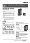
Names of Parts
Front panel
Temperature
unit
No.1 display
Operation
indicators
No.2 display
Up key
Level key
Mode key
1-1-2
Down key
Display
No. 1 display
Displays the process value or parameter type.
No. 2 display
Displays the set point, manipulated variable or set value (setup) of the parameter.
Operation indicators
1. ALM1 (alarm 1)
Lights when alarm 1 output is ON.
ALM2 (alarm 2)
Lights when alarm 2 output is ON.
2. HB (heater burnout alarm display)
Lights when a heater burnout is detected.
3. OUT1, 2 (control output 1, control output 2)
Lights when control output 1 and/or control output 2 are ON.
Note, however, that OUT1 is out at all times when control output 1 is current output.
4. STOP (stop)
Lights when control of the E5CN has been stopped.
During control, this indicator lights when an event or the run/stop function has become stopped. Otherwise, this indicator is out.
5. CMW (communications writing control)
Lights when communications writing is “enabled” and is out when it is “disabled.”
Temperature unit
The temperature unit is displayed when the display unit parameter is set to a
temperature. Indication is determined by the currently selected “temperature
unit” parameter set value. When this parameter is set to “°C”, “c” is displayed,
and when set to “°F”, “f” is displayed.
2
Section 1-2
I/O Configuration and Main Functions
1-1-3
How to use keys
The following describes the basic functions of the front panel keys.
(level) key
Press this key to select the setting levels. The setting level is selected in order
“operation level” ←→ “adjustment level”, “initial setting level” ←→ “communications setting level”.
(mode) key
Press this key to select parameters within each level.
(up) key
Each press of this key increments values displayed on the No.2 display. Holding down this key continuously increments values.
(down) key
Each press of this key decrements values displayed on the No.2 display. Holding down this key continuously decrements values.
+
key
combination
1-2
This key combination sets the E5CN to the “protect level.” For details on the
protect level, see Section 5 Parameters.
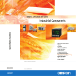
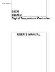
I/O Configuration and Main Functions
1-2-1
I/O configuration
E5CN
OUT1
Control output 1
Temperature
input/analog input
Control output 1
Control output 2
*HBA
Heating
and cooling
CT input
OUT2
Alarm output 2
Standard
ALM2
*
Event input 2ch
SP input from external
digital switch function
andRun/Stop function
Alarm 2
Controller
Alarm 1
ALM1
HB
HBA
Alarm output 1
Input error
Communications *
function
"*" marked items are options.
3
I/O Configuration and Main Functions
1-2-2
Section 1-2
Main functions
The following introduces the main functions of the E5CN. For details on each
function and how to use the functions, see Section 3 onwards.
Input sensor types
• The following input sensors can be connected for temperature input:
Thermocouple
: K, J, T, E, L, U, N, R, S, B
Infrared temperature sensor type : ES1A
: K(10 to 70°C), K(60 to 120°C),
K(115 to 165°C), K (160 to 260°C)
Platinum resistance thermometer
: Pt100, JPt100
Analog input
: 0 to 50 mV
Control output
• Control output is either relay, voltage output or current output depending
on the model of E5CN.
• If you select heating and cooling control on the E5CN-@2@@, alarm 2
output is used as cooling side output. So, use alarm 1 if an alarm is
needed in heating and cooling control.
Alarms
• Alarms are supported on the E5CN-@2@@. Set the alarm type and alarm
value, or upper- and lower-limit alarms.
• If necessary, a more comprehensive alarm function can be achieved by
setting the “standby sequence”, “alarm hysteresis”, “close in alarm/open
in alarm” and Alarm latch ON/OFF parameters.
• When the input error output is set to “ON”, alarm output 1 turns ON when
an input error occurs.
Control adjustment
• Optimum PID constants can be set easily by AT (auto-tuning) and ST
(self-tuning).
Event input
• When the option event input unit E53-CNHB is mounted in the E5CN, the
following functions can be achieved by event input:
Set point selection (multi-SP max. 4 points) and run/stop
HBA
• The heater burnout alarm (HBA) function is supported when the option
unit (E53-CNHB or E53-CNH03) is mounted in the E5CN.
Communications function
• Communications according to CompoWay/F* and Sysway are supported
when the option communications unit E53-CNH03 is mounted in the
E5CN.
Communications are carried out over the RS-485 interface.
Note
4
CompoWay/F is a general-purpose serial communications-based unified communications procedure developed by OMRON. CompoWay/F uses commands compliant with the well-established FINS, together with a unified frame
format on OMRON programmable controllers to facilitate communications
between personal computers and components.
Section 1-3
How Setup Levels Are Configured and Operating the Keys on the Front Panel
1-3
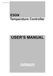
How Setup Levels Are Configured and Operating the Keys
on the Front Panel
Parameters are divided into groups, each called a “level”. Each of the set values (setup items) in these levels are called a “parameter.” The parameters on
the E5CN are divided into the following seven levels:
Power ON
Operation level
Adjustment level
+
key
1 second min.
key
Less than
1 second
key 3 seconds min.
key
1 second min.
25
100
key
The PV display flashes after one second.
25
100
+
key
3 seconds min.
Control stops.
Initial setting level
key
Less than
1 second
Communications
setting level
+
key
The PV display
flashes
Protect level
Password input
set value "-169"
key
1 second min.
Advanced
function setting level
Password input
set value "1201"
Note :
Communications setting level is displayed
when the optional communication unit
E53-CNH03 is mounted.
Control in progress
Calibration level
Control stopped
Control in
Progress
Control Stopped
Protect level
-
Operation level
-
Adjustment level
-
Initial setting level
-
Advanced function setting level
-
Calibration level
-
Communications setting level
-
: Indicates items that can be set.
Of these levels, the initial setting level, communications setting level,
advanced function setting level and calibration level can be used only when
control has stopped. Note that controller outputs are stopped when any of
these four levels are selected.
5
How Setup Levels Are Configured and Operating the Keys on the Front Panel
Section 1-3
Protect level
• To move the mode at this level, simultaneously press the
and
keys for at least three seconds in the operation level or adjustment level.
This level is for preventing unwanted or accidental modification of parameters. Protected levels will not be displayed, and so the parameters in that
level cannot be modified.
Operation level
• This level is displayed when you turn the power ON. You can move to the
protect level, initial setting level and adjustment level from this level.
• Normally, select this level during operation. During operation, the process
value, set point and manipulated variable can be monitored, and the
alarm value and upper- and lower-limit alarms can be monitored and
modified.
Adjustment level
• To move the mode at this level, press the
ond.
key for less than one sec-
• This level is for entering set values and offset values for control. This level
contains parameters for setting the AT (auto-tuning), communications
writing enable/disable, hysteresis, multi-SP, input shift values, heater
burnout alarm (HBA) and PID constants. You can move to the top parameter of the initial setting level and operation level from here.
Initial setting level
• To move the mode at this level, press the
key for at least three seconds in the operation level or adjustment level. The PV display flashes
after one second. This level is for specifying the input type, selecting the
control method, control period, setting direct/reverse action and alarm
type. You can move to the advanced function setting level or communications setting level from this level. To return to the operation level, press the
key for at least one second. To move to the communications setup
level, press the
key for less than one second.
Advanced function setting
level
• To select this level, you must enter the password (“-169”) in the initial setting level.
• You can move to the calibration level only from this level.
• This level is for setting the automatic return of display mode, MV limitter,
event input assignment, standby sequence, alarm hysteresis, ST (selftuning) and for moving to the user calibration level.
Communications setting
level
• To move the mode at this level, press the
key for less than one second in the initial setting level. When the communications function is used,
set the communications conditions in this level. Communicating with a
personal computer (host computer) allows set points to be read and written, and manipulated variables to be monitored.
Note
Calibration level
This level is available if communications card (E53-CNH03) is fitted
to the unit.
• To move the mode at this level, you must enter the password “1201” in the
advanced function setting level. This level is for offsetting deviation in the
input circuit.
• You cannot move to other levels by operating the keys on the front panel
from the calibration level. To cancel this level, turn the power OFF then
back ON again.
6
Section 1-4
Communications Function
1-3-1
Selecting parameters
• To select parameters in each level, press the
key. Each press of the
key advances to the next parameter. For details on each parameter,
see Section 5.
Parameter
1
Parameter
2
Parameter
3
Parameter
n
1-3-2
Fixing settings
• If you press the
key at the final parameter, the display returns to the
top parameter for the current level.
• To change parameter settings or setup, specify the setting using the
or
the
keys, and either leave the setting for at least two seconds or press
key. This fixes the setting.
• When another level is selected, the parameter and setting on the display
are fixed.
• When you turn the power OFF, you must first fix the settings or parameter
setup (by pressing the
key). The settings and parameter setup are
sometimes not changed by merely pressing the
1-4
or
keys.
Communications Function
The E5CN can be provided with a communications function that allows you to
check and set controller parameters on a host computer. If the communications function is required, mount the option unit E53-CNH03 in the E5CN. For
details on the communications function, see the separate “Communications
Functions User’s Manual.”
Follow the procedure below to move to the communications setting level.
1,2,3...
1. Press the
key for at least three seconds in the “operation level”. The
level moves to the “initial setting level”.
2. Press the
key for less than one second. The “initial setting level”
moves to the “communications setting level”.
7
Section 1-4
Communications Function
3. Pressing the
figure.
4. Press the
key advances the parameters as shown in the following
or
keys to change the parameter setups.
Communications unit No.
Baud rate
Data bit
Stop bit
Parity
Setting up
communications data
Parameter
Communications unit No.
Baud rate
Data bit
Stop bit
Parity
8
Set the E5CN communications specifications so that they match the communications setup of the host computer.
Displayed
Characters
Set (monitor) Value
A:; 0 to 99
.<? 1.2, 2.4, 4.8, 9.6, 19.2
Settings
, , , ,
81: 7, 8
?.5@ 1, 2
<>@E None, even, odd
:;:1,1B1:,;00
Default
Unit
1
9.6
None
kbps
7
bit
2
Even
bit
None
SECTION 2
PREPARATIONS
2-1
2-2
2-3
Installation. . . . . . . . . . . . . . . . . . . . . . . . . . . . . . . . . . . . . . . . . . . . . . . . . . . .
10
2-1-1
Dimensions . . . . . . . . . . . . . . . . . . . . . . . . . . . . . . . . . . . . . . . . . . . .
10
2-1-2
Panel cutout . . . . . . . . . . . . . . . . . . . . . . . . . . . . . . . . . . . . . . . . . . .
10
2-1-3
Setting up the option units . . . . . . . . . . . . . . . . . . . . . . . . . . . . . . . .
11
2-1-4
Mounting. . . . . . . . . . . . . . . . . . . . . . . . . . . . . . . . . . . . . . . . . . . . . .
12
Wiring Terminals. . . . . . . . . . . . . . . . . . . . . . . . . . . . . . . . . . . . . . . . . . . . . . .
12
2-2-1
Terminal arrangement . . . . . . . . . . . . . . . . . . . . . . . . . . . . . . . . . . . .
12
2-2-2
Precautions when wiring. . . . . . . . . . . . . . . . . . . . . . . . . . . . . . . . . .
13
2-2-3
Wiring . . . . . . . . . . . . . . . . . . . . . . . . . . . . . . . . . . . . . . . . . . . . . . . .
13
Requests at Installation . . . . . . . . . . . . . . . . . . . . . . . . . . . . . . . . . . . . . . . . . .
16
2-3-1
To ensure prolonged use . . . . . . . . . . . . . . . . . . . . . . . . . . . . . . . . . .
16
2-3-2
To reduce the influence of noise . . . . . . . . . . . . . . . . . . . . . . . . . . . .
16
2-3-3
To ensure high-precision measurement . . . . . . . . . . . . . . . . . . . . . .
16
9
Section 2-1
Installation
Installation
2-1-1
Dimensions
E5CN
(Unit: mm)
E5CN
102
93
48 × 48
78
58
44.8 × 44.8
9
48.8
2-1
1
11
6
2
12
7
3
13
8
4
14
9
5
15
10
• The E5CN-@-500 is provided with a terminal cover.
2-1-2
Panel cutout
(Unit: mm)
When mounted separately
When group-mounted
+1.0
+0.6
45 0
45 0
+0.6
60 min.
45 +0.6
0
(48 × number of units -2.5) 0
• Insert the controller through the hole in the panel from the front, and push
the adapter on from the rear. Push the adapter up to the back of the panel
ensuring that the controller is pushed all the way in, removing any gap
between the controller, panel and adapter. Finally use the two screws on
the adapter to secure the unit in place.
• To mount the E5CN so that it is waterproof, insert the waterproof packing
onto the E5CN. The E5CN cannot be waterproofed when the E5CN is
group-mounted.
• The recommended panel thickness is 1 to 5 mm.
• Maintain the specified mounting space between each controller. Controllers must not be closely mounted vertically.
• When two or more E5CNs are mounted, make sure that the surrounding
temperature does not exceed the allowable operating temperature given
in the specifications.
10
Section 2-1
Installation
2-1-3
Setting up the option units
If communications, event input and heater burnout functions are required,
mount the communications unit (E53-CNH03 or E53-CN03) or the event input
unit (E53-CNHB or E53-CNB).
The heater burnout function is supported on either of these two option units.
Option units
Name
Communications Unit
Model
E53-CNH03 (For relay and voltage output)
Function
RS-485 communication and heater burnout alarm
Event Input Unit
E53-CN03 (For current output)
E53-CNHB (For relay and voltage output)
RS-485 communication
Event input and heater burnout alarm
E53-CNB (For current output)
Event input
• Terminal label:x 1
Assembling the unit
(1)
Regular flat blade
screwdriver
(units: mm)
20 min.
(4)
(2)
(1)
(3)
1,2,3...
1. Insert the tools (see drawing above) into the slots (one on the top and one
on the bottom) and release the hooks.
2. Insert the tool into the gap between the front and rear, and slightly draw out
the front panel. Then, draw out the front panel towards you holding it by its
top and bottom sides.
3. Match the upper and lower claws with the connection points and insert the
option unit. Mount the option unit in the center.
4. Before you push the unit back into the case, make sure that the watertight
packing is in place. Push the unit back into the rear case until you hear a
click. When you do this, hold down the hooks on the top and bottom of the
rear case so that they are firmly hooked in place.
11
Section 2-2
Wiring Terminals
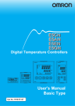
2-1-4
Mounting
Terminal cover
How to attach the E5CN
on the panel
1,2,3...
1. Insert the E5CN into the mounting hole in the panel.
2. Push the adapter along the E5CN body from the terminals up to the panel,
and fasten temporarily.
3. Tighten the two fixing screws on the adapter. When tightening screws,
tighten the two screws alternately keeping the torque to approximately
0.29 to 0.39 N⋅m.
How to attach the terminal
cover
2-2
2-2-1
Make sure that the “UP” mark is facing up, and then fit the terminal cover
(E53-COV10) into the holes on the top and bottom.
The E5CN-@-500 is provided with a terminal cover.
Wiring Terminals
Terminal arrangement
E5CN
E53-CNHB
1
11
−
Analog input
B
B
−
−
2
12
7
3
13
8
4
14
9
5
15
10
ALM2/
ALM1/heater Control output2
burnout/Input error
12
11
EV1
12
EV2
13
Input power supply
+
Pt
TC
Two input power supplies are available: 100 to 240 VAC or 24 VDC.
+
Communications/
CT
6
Control output 1
A
Event input/
CT
Alarm output
+
Voltage output/relay
output/Current output
E53-CNH03
−
+
11
EV1 12
A(−)
EV2 13
Do not
use
+
14
14
CT
CT
15
RS-485
B(+)
15
Section 2-2
Wiring Terminals
2-2-2
Precautions when wiring
• Separate input leads and power lines in order to protect the E5CN and its
lines from external noise.
• Use AWG28 or larger twisted pair cable.
• We recommend using solderless terminals when wiring the E5CN.
• Tighten the terminal screws using a torque no greater than 0.74 N⋅m.
• Use the following type of solderless terminals for M3.5 screws.
7.2 mm max.
7.2 mm max.
2-2-3
Wiring
Power supply
• Connect to terminal Nos. 9 and 10. The following table shows the specifications.
Input power supply
100 to 240 VAC, 50/60 Hz
7VA
E5CN
24 VAC, 50/60 Hz
24 VDC (no polarity)
4VA
3W
• Standard insulation is applied to the power supply I/O sections. If reinforced insulation is required, connect the input and output terminals to a
device without any exposed current-carrying parts or to a device with
standard insulation suitable for the maximum operating voltage of the
power supply I/O section.
Input
• Connect to terminal Nos. 3 to 5 as follows according to the input type.
3
4
−
5
+
3
4
3
4
5
5
−
v
+
Thermocouple Platinum resistance Analog
thermometer
input
Control output 1
• Terminal Nos. 1 and 2 are for control output. The following diagrams show
the available outputs and their internal equalizing circuits.
+V
+V
Temperature
controller
1
+
−
1
1 +
L
L
2
Relay
GND 2
Voltage
GND
2
−
Current
• The following table shows the specifications for each output type.
Output type
Relay
Voltage (PNP)
Specifications
250 VAC, 3A (resistive load), electrical life: 100,000 operations
PNP type, 12 VDC, 21 mA (with short-circuit protection)
Current
4 to 20mA DC, load : 600Ω max., resolution : approx. 2,600
13
Section 2-2
Wiring Terminals
• The voltage output (control output) is not electrically insulated from the
internal circuits. When using a grounding thermocouple, do not connect
the control output terminals to the ground. If the control output terminals
are connected to the ground, errors will occur in the measured temperature values as a result of leakage current.
Alarm output/Control
output 2
• On the E5CN-@2@@@-500, alarm output 1 (ALM1) is across terminal
Nos.7 and 8, and alarm output 2 (ALM2) is across terminal Nos.6 and 8.
When heating and cooling control is used, alarm output 2 becomes cooling output.
• When the input error output is set to “ON”, alarm output 1 turns ON when
an input error occurs.
• When the option unit (E53-CNHB or E53-CNH03) is mounted on the
E5CN, an OR of alarm output 1 and the heater burnout alarm will be output. To disable alarm output 1 and output only the heater burnout alarm
on terminals 7 and 8, set the mode of the alarm output 1 to 0.
• The equivalent circuits for terminal Nos. 6 to 8 are shown in the following
diagram.
6
ALM2/OUT2
7
ALM1/heater burnout alarm/Input error
8
• Relay specifications are as follows:
SPST-NO 250 VAC 1A
CT input
• When the option unit (E53-CNH03 or E53-CNHB) is mounted on the
E5CN and the heater burnout function is used, connect a current transformer (CT) across terminal Nos. 14 and 15.
14
CT
15
Event input
• When the option event input unit E53-CNHB is mounted in the E5CN and
event input is used, connect to terminal Nos. 11 to 13.
11
12
EV1
13
EV2
• Use event inputs under the following conditions:
• The output current is approx. 7mA.
Contact inputON: 1 kΩ max., OFF: 100kΩ min.
No-contact inputON: residual voltage 1.5 V max., OFF: leakage current 0.1 mA max.
14
Section 2-2
Wiring Terminals
Polarities during no-contact input are as follows:
11
12
13
Communications
−
EV1
+
EV2
+
• When the option communications unit E53-CNH03 is mounted in the
E5CN for communicating with a host computer, connect the communications cable across terminal Nos. 11 and 12.
Specify both ends of the transmission path including the host computer as
the end node (that is, connect terminators to both ends).
The maximum terminal resistance is 54 Ohms.
11
B(+)
12
A(−)
RS-485
Communications Unit Wiring Diagram
Host computer
Shielded cable
RS-485
−
+
FG
A<B : "1" mark
A>B : "2" space
E5CN (No.1)
RS-485
No Abbr.
12 A(−)
11 B(+)
E5CN (No.31)
RS-485
No Abbr.
12 A(−)
11 B(+)
Terminator (120W, 1/2 W)
• The RS-485 connection can be either one-to-one to one-to-N. Up to 32
units including the host computer can be connected in one-to-N systems.
Use shielded, twisted pair cable (AWG 28 or larger) and keep the total
cable length to 500m.
15
Section 2-3
Requests at Installation
2-3
2-3-1
Requests at Installation
To ensure prolonged use
Use the temperature in the following operating environment:
Temperature : –10 to +55°C (icing and condensation not allowed)
Humidity : 25 to 85%
When the temperature controller is incorporated in a control panel, make sure
that the controller’s ambient temperature and not the panel’s ambient temperature does not exceed 55°C.
The life of electronic equipment such as temperature controllers is influenced
not only by the life determined by the relay switching count but also by the life
of the electronic components used internally. The service life of components
is dependent on the ambient temperature: the higher the ambient temperature
becomes, the shorter the service life becomes, and vice versa. For this reason, the service life of the temperature controller can be extended by lowering
its internal temperature.
Gang-mounting two or more temperature controllers, or mounting temperature controllers above each other may cause heat to build up inside the temperature controllers, which will shorten their service life. When mounting
temperature controllers like this, forced cooling measures such as a cooling
fan for cooling the temperature controllers must be taken into consideration.
Prevent only the terminal block from being cooled. Otherwise, this may result
in a measurement error.
2-3-2
To reduce the influence of noise
To reduce induction noise, the leads on the temperature controller’s terminal
block must be wired separately from large-voltage/large-current power leads.
Also, avoid wiring leads in parallel with power leads or in the same wiring
path. Other methods such as separating conduits and wiring ducts, or using
shield wire are also effective.
Attach a surge absorber or noise filter to peripheral equipment that generates
noise (in particular, motors, transformers, solenoids, or other equipment that
has a magnetic coil or other inductance component).
When a noise filter is used at the power supply, first check the voltage or current, and attach the noise filter as close as possible to the temperature controller.
Also, install the temperature controller as far away as possible from equipment that generates strong, high frequency (e.g. high-frequency welders,
high-frequency sewing machines) or surges.
2-3-3
To ensure high-precision measurement
When the thermocouple leads are extended, be sure to use a compensating
lead wire matched to the type of thermocouple.
When the platinum resistance detector leads are extended, use the lead having the smallest resistance to equalize the resistance of the three leads.
Install the temperature controller so that it is horizontal.
If there is a large error in the measurement values, make sure that input compensation has been set correctly.
16
SECTION 3
BASIC OPERATION
3-1
3-2
Initial Setup Examples . . . . . . . . . . . . . . . . . . . . . . . . . . . . . . . . . . . . . . . . . .
18
Setting the Input Type . . . . . . . . . . . . . . . . . . . . . . . . . . . . . . . . . . . . . . . . . . .
20
3-2-1
Input type . . . . . . . . . . . . . . . . . . . . . . . . . . . . . . . . . . . . . . . . . . . . .
20
Selecting °C/°F . . . . . . . . . . . . . . . . . . . . . . . . . . . . . . . . . . . . . . . . . . . . . . . .
21
3-3-1
Temperature unit . . . . . . . . . . . . . . . . . . . . . . . . . . . . . . . . . . . . . . . .
21
3-4
Selecting PID Control or ON/OFF Control . . . . . . . . . . . . . . . . . . . . . . . . . .
22
3-5
Setting Output Specifications . . . . . . . . . . . . . . . . . . . . . . . . . . . . . . . . . . . . .
23
3-5-1
Control period. . . . . . . . . . . . . . . . . . . . . . . . . . . . . . . . . . . . . . . . . .
23
3-5-2
Direct/reverse operation . . . . . . . . . . . . . . . . . . . . . . . . . . . . . . . . . .
23
3-3
3-6
3-7
Setting the SP . . . . . . . . . . . . . . . . . . . . . . . . . . . . . . . . . . . . . . . . . . . . . . . . .
25
3-6-1
Changing the SP . . . . . . . . . . . . . . . . . . . . . . . . . . . . . . . . . . . . . . . .
25
Executing ON/OFF Control . . . . . . . . . . . . . . . . . . . . . . . . . . . . . . . . . . . . . .
26
3-7-1
ON/OFF Control. . . . . . . . . . . . . . . . . . . . . . . . . . . . . . . . . . . . . . . .
26
3-7-2
Setup . . . . . . . . . . . . . . . . . . . . . . . . . . . . . . . . . . . . . . . . . . . . . . . . .
27
Determining PID Constants (AT, ST, manual setup) . . . . . . . . . . . . . . . . . . .
28
3-8-1
AT (auto-tuning) . . . . . . . . . . . . . . . . . . . . . . . . . . . . . . . . . . . . . . . .
28
3-8-2
ST (self-tuning). . . . . . . . . . . . . . . . . . . . . . . . . . . . . . . . . . . . . . . . .
30
3-8-3
ST start conditions . . . . . . . . . . . . . . . . . . . . . . . . . . . . . . . . . . . . . .
30
3-8-4
ST stable range . . . . . . . . . . . . . . . . . . . . . . . . . . . . . . . . . . . . . . . . .
31
3-8-5
Manual setup. . . . . . . . . . . . . . . . . . . . . . . . . . . . . . . . . . . . . . . . . . .
31
Alarm Outputs. . . . . . . . . . . . . . . . . . . . . . . . . . . . . . . . . . . . . . . . . . . . . . . . .
32
3-9-1
Alarm type . . . . . . . . . . . . . . . . . . . . . . . . . . . . . . . . . . . . . . . . . . . .
33
3-9-2
Alarm value. . . . . . . . . . . . . . . . . . . . . . . . . . . . . . . . . . . . . . . . . . . .
34
3-10 Heater Burnout Alarm (HBA). . . . . . . . . . . . . . . . . . . . . . . . . . . . . . . . . . . . .
35
3-10-1 HBA detection . . . . . . . . . . . . . . . . . . . . . . . . . . . . . . . . . . . . . . . . .
35
3-8
3-9
3-10-2 Operating conditions. . . . . . . . . . . . . . . . . . . . . . . . . . . . . . . . . . . . .
35
3-10-3 Setup . . . . . . . . . . . . . . . . . . . . . . . . . . . . . . . . . . . . . . . . . . . . . . . . .
36
3-10-4 How to calculate detection current values . . . . . . . . . . . . . . . . . . . .
37
3-10-5 Example . . . . . . . . . . . . . . . . . . . . . . . . . . . . . . . . . . . . . . . . . . . . . .
37
3-11 Requests during Operation . . . . . . . . . . . . . . . . . . . . . . . . . . . . . . . . . . . . . . .
38
17
Section 3-1
Initial Setup Examples
3-1
Initial Setup Examples
On previous controllers, sensor input type, alarm type and control period were
set by the DIP switches. These hardware settings are now set in parameters
in setup menus. The
and
keys are used to switch between setup
menus, and the amount of time that you hold the keys down for determines
which setup menu you move to. This section describes two typical examples.
Typical example 1
Input type:
Control method:
Alarm type:
Alarm value 1:
Set point:
0 K thermocouple -200 to 1300°C
ON/OFF control
2 upper limit
20°C (deviation)
100°C
Setup procedure
Power ON
Power ON
Operation level
25 Process value/
0
set point
Press
key for at least
three seconds.
Control stops.
Initial setting level
Initial setting level
Set input
specifications
Set control
specifications
Set alarm type
in-t
Check input
type.
4
Check that
control is
ON/OFF control.
cntl
onof
alt1
Check alarm
type.
2
Input type
0
In ON/OFF onof
control
stop
In PID control
Alarm 1 type 2
Press
key for at
least one second.
Operation level
Press
keys
to set point to
"100°C".
Operation level
Set alarm values
Start operation
18
Make sure that
control is
running.
25
100
run
During run run
During stop stop
al-1
Alarm value 1 20
r-5
Press
keys
to set alarm
value to "20°C".
Process value/
set point 100
20
Start operation
Section 3-1
Initial Setup Examples
Typical example 2
Input type:
4 T thermocouple -200 to 400°C
Control method:
PID control
Calculate PID constants by AT (auto-tuning)
execution.
Alarm type:
2 upper limit
Alarm value 1:
30°C (deviation)
Set point:
150°C
Setup procedure
Power ON
Power ON
Operation level
25 Process value/
0
set point
Press
key for at
least three seconds.
Control stops.
Initial setting level
Initial setting level
Press
keys
to select input
type.
Set input
specifications
Press
keys
to set PID control.
Set control
specifications
Press
keys
to set ST to OFF.
Set alarm type
Check the
control period.
Check alarm
type.
Operation level
PV/SP
After AT execution
Press
keys
to set point to
"150°C".
During AT execution
Adjustment level
Adjustment level
AT execution
(when PID control is selected)
While AT is being
executed, SP will flash
After AT execution
During AT execution
Execute AT
(auto-tuning).
Operation level
Make sure
that set point
is "150°C".
Make sure that
control is
running.
in-t
4
cntl
pid
Input type 4
In ON/OFF onoff
control
pid
In PID control
st
To execute ST on
cp
Control period
(heat) (unit:
off To cancel ST off
20 seconds) 20
alt1
2
Alarm 1 type 2
Press
key for at
least one second.
25
150
Process value/
set point 150
Press
key for
less than 1 second.
at
To execute AT on
on To cancel AT off
Press
key for
less than 1 second.
25
Process value/
150 set point 150
r-5
During run run
run During stop stop
Operation level
Set alarm values
Start operation
Press
keys
to set alarm value
to "30°C".
al-1
30
Alarm value 1 30
Start program execution
19
Section 3-2
Setting the Input Type
3-2
Setting the Input Type
The E5CN supports four input types: platinum resistance thermometer, thermocouple, infrared temperature sensor and analog inputs. Set the input type
matched to the sensor used in the “input type” parameter. The E5CN specifications support two types of inputs, platinum resistance thermometer input
types and thermocouple input type, whose set values differ. Check the type of
E5CN at purchase.
3-2-1
Input type
Setting the input type “thermocouple K-20.0 to 500.0°C”.
Operation Procedure
Operation level
1,2,3...
25
Initial setting level
Input type
1. Press the
key for at least three seconds to move from the “operation
level” to the “initial setting level”.
2. Press the
key to enter the set value of the desired sensor. When you
use K thermocouple (-20.0 to 500.0°C), enter “1” as the set value.
Hint:
The set value is fixed if you do not operate the keys on the front panel
for two seconds after changing the parameter, or by pressing the
or
keys.
List of Input Types
Input type
Platinum resistance thermometer input
type
Platinum
resistance
thermometer
Name
Pt100
JPt100
Input type
Thermocouple
input type
Thermocouple
Name
K
0
-200 to 850 (°C)/ -300 to 1500 (°F)
1
-199.9 to 500.0 (°C)/ -199.9 to 900.0 (°F)
2
0.0 to 100.0 (°C)/ 0.0 to 210.0 (°F)
3
-199.9 to 500.0 (°C)/ -199.9 to 900.0 (°F)
4
0.0 to 100.0 (°C)/ 0.0 to 210.0 (°F)
Set
Value
0
-200 to 1300 (°C)/ -300 to 2300 (°F)
-20.0 to 500.0 (°C)/ 0.0 to 900.0 (°F)
2
-100 to 850 (°C)/ -100 to 1500 (°F)
3
-20 to 400.0 (°C)/ 0.0 to 750.0 (°F)
T
4
-200 to 400 (°C)/ -300 to 700 (°F)
17
-199.9 to 400.0 (°C)/ -199.9 to 700.0 (°F)
5
0 to 600 (°C)/ 0 to 1100 (°F)
L
6
-100 to 850 (°C)/ -100 to 1500 (°F)
U
7
-200 to 400 (°C)/ -300 to 700 (°F)
18
-199.9 to 400.0 (°C)/ -199.9 to 700.0 (°F)
8
-200 to 1300 (°C)/ -300 to 2300 (°F)
R
9
0 to 1700 (°C)/ 0 to 3000 (°F)
S
10
0 to 1700 (°C)/ 0 to 3000 (°F)
B
11
100 to 1800 (°C)/ 300 to 3200 (°F)
10 to 70°C
12
0 to 90 (°C)/ 0 to 190 (°F)
60 to 120°C
13
0 to 120 (°C)/ 0 to 240 (°F)
115 to 165°C
14
0 to 165 (°C)/ 0 to 320 (°F)
160 to 260°C
15
0 to 260 (°C)/ 0 to 500 (°F)
0 to 50mV
16
One of the following ranges depending on the
results of scaling:
-1999 to 9999, -199.9 to 999.9,
-19.99 to 99.99, -1.999 to 9.999
Shaded ranges indicate default settings.
20
Input Temperature Setup Range
J
N
Analog input
Input Temperature Setup Range
1
E
Infrared
temperature
sensor
ES1A
Set
Value
Selecting °C/°F
3-3
3-3-1
Section 3-3
Selecting °C/°F
Temperature unit
• Select either “°C” or “°F” as the temperature unit.
• Set the temperature unit in the “temperature unit” parameter of “initial setting level”. Default is “c: °C”.
Select “°C”.
Operation Procedure
Operation level
30
1,2,3...
Initial setting level
Input type
1. Press the
key for at least three seconds to move from the “operation
level” to the “initial setting level”.
2. Select the “temperature unit” parameter by pressing the
Press the
c : °C
or
key.
keys to select either “°C” or “°F”.
f : °F
3. To return to the “operation level” press the
key for at least one second.
Temperature unit
21
Selecting PID Control or ON/OFF Control
3-4
Section 3-4
Selecting PID Control or ON/OFF Control
The E5CN supports two control methods, 2-PID control and ON/OFF control.
The control method is selected by the “PID / ON/OFF” parameter in the “initial
setting level”. When this parameter is set to “pid”, 2-PID control is set, and
when set to “onof”, ON/OFF control is set (default).
2-PID control
PID control is set by AT (auto-tuning), ST (self-tuning) or manual setup.
For PID control, set the PID constants in the “proportional band (P)”, “integral
time (I)” and “derivative time (D)” parameters.
ON/OFF control
In “ON/OFF” control, the control output is turned ON when the process value
is lower than the current set point, and the control output is turned OFF when
the process value is higher than the current set point (reverse operation).
22
Section 3-5
Setting Output Specifications
3-5
Setting Output Specifications
3-5-1
Control period
Control
period
(OUT1)
Control
period
(OUT2)
• Set the output period (control period). Though a shorter period provides
better control performance, we recommend setting the control period to
20 seconds or more taking the life expectancy in the case of relay output
into consideration. If necessary, readjust the control period by trial operation, for example, when the control period parameters are set to their
defaults.
• Set the control period in the “control period (OUT1)” and “control period
(OUT2)” parameters (initial setting level). Default is “20 seconds”.
• The “control period (OUT2)” parameter can be used only in heating and
cooling control.
• Whenever control output 1 is the current output, “control period (OUT1)”
cannot be used.
3-5-2
Direct/reverse operation
• “Direct operation” refers to control where the manipulated variable is
increased according to the increase in the process value. Alternatively,
“Reverse operation” refers to control where the manipulated variable is
decreased according to the increase in the process value.
Manipulated variable
Manipulated variable
100%
100%
0%
0%
Low temperature Set value
Direct operation
High temperature
Low temperature Set value
High temperature
Reverse operation
For example, when the process value (PV) (temperature) is lower than the set
point (SP) (temperature) in a heating control system, the manipulated variable
increases by the difference between the PV and SP values.
Accordingly, this becomes “reverse operation” in a heating control system, or
alternatively, “direct operation” in a cooling control system.
• Direct/reverse operation is set in the “direct/reverse operation” parameter
(initial setting level). The “direct/reverse operation” parameter default is
“reverse operation”.
23
Section 3-5
Setting Output Specifications
In this example, let’s monitor the “input type”, “temperature unit”, “direct/
reverse operation” and “control period (OUT1)” parameters.
Operation Procedure
“input type” = “0”: K thermocouple
“temperature unit” = “c”: °C
“direct/reverse operation” = “or-r”: reverse operation
“control period (OUT1)” = “20 (secs)”
Operation level
1,2,3...
1. Press the
key for at least three seconds to move from the “operation
level” to the “initial setting level”.
2. The input type is displayed. When you are setting the input type for the first
time, “0”: K thermocouple is set. (“0” is set in the case of a platinum resistance thermometer.) To select a different sensor, press the
or
Initial setting level
Input type
keys.
3. Select the “temperature unit” parameter by pressing the
is “c”: °C. To select “f”: °F, press either of the
Temperature unit
cp
Control period
(OUT1)
20
Direct/reverse
operation
Operation level
PV/SP
24
or
key. Default
keys.
4. Select the “control period (OUT1) parameter by pressing the
Default is “20”.
key.
5. Select the “direct/reverse operation” parameter by pressing the
key.
Default is “or-r”: reverse operation. To select “or-d”: direct operation,
press either
or
keys.
6. To return to the “operation level” press the
key for at least one second.
Section 3-6
Setting the SP
3-6
Setting the SP
The “operation level” is displayed when the E5CN is turned ON. The upper
display (No.1 display) displays the process value, and the lower display (No.2
display) displays the set point.
Operation level
3-6-1
Changing the SP
• The set point cannot be changed when the “operation/adjustment protection” parameter is set to “3”. For details, see “4.9 Using the Key Protect
Levels.”
• To change the set point, press the
or
keys in the “PV/SP”
parameter (operation level), and set the desired set value. The new set
point is selected two seconds after you have specified the new value.
• Multi-SP is used to switch between two or four set points.
See “4.5 To Use Event Input” for details.
In this example, let’s change the set point from “0°C” to “200°C”.
Operation Procedure
Operation level
1,2,3...
1. Normally, the “PV/SP” parameter is displayed. The set point is “0°C”.
2. Press the
or
keys until the set point changes to “200°C”.
25
Section 3-7
Executing ON/OFF Control
3-7
Executing ON/OFF Control
In “ON/OFF” control, the control output turns OFF when the currently controlled temperature reaches a preset set point. When the manipulated variable
turns OFF, the temperature begins to fall and the control turns ON again. This
operation is repeated at a certain point. At this time, how much the temperature must fall before control turns ON again is determined by the “hysteresis
(OUT1)” parameter. Also, how much the manipulated variable must be
adjusted in response in the increase or decrease in the process value is
determined by “direct/reverse operation” parameter.
3-7-1
ON/OFF Control
• Switching between 2-PID control and ON/OFF control is carried out by the
“PID / ON/OFF” parameter (initial setting level). When this parameter is
set to “pid”, 2-PID control is selected, and when set to “onof”, ON/OFF
control, is selected. Default is “onof”.
Hysteresis
• In ON/OFF control the hysteresis is used as a differential for switching the
output ON when the temperature moves away from the required set point,
and is used give stability around the set point.
The control output (OUT1) and control output (OUT2) functions are set in
the hysteresis (OUT1) and hysteresis (OUT2) functions respectively.
In standard heating or cooling control, the hysteresis can only be set on
the side approaching the set point.
Hysteresis (OUT1)
Revers operation
ON
OFF
PV
Set point
3-position control
• In heating and cooling control, a dead band (an area where both control
outputs are “0”) can be set to either the heating or cooling side. So, 3position control is made possible.
Dead band
Revers operation
Hysteresis (OUT2)
Hysteresis (OUT1)
ON
Heating
side
Cooling
side
OFF
PV
Set point
Parameters
26
Symbol
?4/
/:@8
;>1B
/0.
/?/
4E?
/4E?
Parameter Name: Level
Description
Standard/heating and cooling: Initial setting level
For specifying control method
PID / ON/OFF: Initial setting level
For specifying control method
Direct/reverse operation: Initial setting level
For specifying control method
Dead band: Adjustment level
Heating and cooling control
Cooling coefficient: Adjustment level
Heating and cooling control
Hysteresis (OUT1): Adjustment level
ON/OFF control
Hysteresis (OUT2): Adjustment level
ON/OFF control
Section 3-7
Executing ON/OFF Control
3-7-2
Setup
To execute ON/OFF control, set the “set point,” “PID / ON/OFF” and “hysteresis” parameters.
Setting the PID / ON/OFF parameter
In this example, let’s first check that the “PID / ON/OFF” parameter is set to
“onof” in the “initial setting level”.
Operation Procedure
1,2,3...
Operation level
PV
1. Press the
key for at least three seconds to move from the “operation
level” to the “initial setting level”.
2. Display the “input type” parameter in the initial setting level.
3. Select the “PID / ON/OFF” parameter by pressing the
key.
4. Check that the set value is “onof” (default).
Initial setting level
Input type
PID / ON/OFF
27
Section 3-8
Determining PID Constants (AT, ST, manual setup)
3-8
3-8-1
Determining PID Constants (AT, ST, manual setup)
AT (auto-tuning)
• When you execute auto-tuning, the optimum PID constants for the set
point during program execution are automatically set by forcibly changing
the manipulated variable to calculate the characteristics (called the “limit
cycle method”) of the control target.
• To execute AT (auto-tuning), specify “on: AT execute”, and to cancel AT
(auto-tuning), specify “off: AT cancel”.
• AT (auto-tuning) cannot be executed during ON/OFF control.
• The result of AT (auto-tuning) is mirrored in the “proportional band (P),”
“integral time (I)” and “derivative time (D)” parameters in the “adjustment
level”.
Adjustment level
Proportional band
Integral time
Derivative time
Description
AT (auto-tuning) is started when the “AT execute/cancel” parameter is set to
“ON”. During execution of AT, the No.1 display for the “AT execute/cancel”
parameter blinks. When AT ends, the “AT execute/cancel” parameter turns
OFF, and the No.1 display stops blinking.
AT execute/cancel
No.1 display
During AT execution
If you move to the “operation level” during AT execution, the No.2 display
blinks to indicate that AT is being executed.
PV/SP
No.2 display
During AT execution
Only the “communications writing”, “run/stop” and “AT execution/cancel”
parameters can be changed during AT execution. Other parameters cannot
be changed.
28
Section 3-8
Determining PID Constants (AT, ST, manual setup)
Execute auto-tuning (AT).
Operation Procedure
1,2,3...
Adjustment Level
AT execute/
cancel
1. Press the
key for less than one second to move from the “operation
level” to the “adjustment level”.
2. Press the
key to start execution of AT (auto-tuning).
“on” is displayed during AT execution.
3. “off” is displayed when AT ends.
4. To return to the “operation level,” press the
key.
Operation level
PV
About PID parameters
When control characteristics are already known, the PID parameters can be set
directly to adjust control.
PID parameters are set in the "proportional band" (P), "integrated time" (I) and
"derivative time" (D) parameters in the "adjustment level".
29
Section 3-8
Determining PID Constants (AT, ST, manual setup)
3-8-2
ST (self-tuning)
The ST (self-tuning) function executes tuning from the start of program execution to calculate PID constants matched to the control target.
Once the PID constants have been calculated, ST is not executed when the
next control operation is started as long as the set point remains unchanged.
st
ST (self-tuning) is executed when the “ST” parameter is set to “ON” in the “initial setting level”.
When the ST function is in operation, be sure to turn the power supply of the
load connected to the control output ON simultaneously with or before starting
operation of the E5CN.
Operation Procedure
Execute self-tuning (ST).
1,2,3...
Initial setting level
Input type
1. Press the
key for at least three seconds to move from the “operation
level” to the “initial setting level”.
2. Select the “ST” parameter by pressing the
3. Press the
key.
key to select “on” (default).
ST
4. To return to the “operation level,” press the
play blinks during self-tuning (ST) execution.
key. The temperature dis-
ST
3-8-3
ST start conditions
Self-tuning by step response tuning (SRT) is started when the following conditions are met after program execution is started and the set point is changed.
Note
At Start of Program Execution
When Set Point Is Changed
1. The set point at the start of program execution differs from the set point (See Note 1)
when the previous SRT was executed.
2. The difference between the temperature at
start of program execution is larger than
(current proportional band×1.27+4°C) or the
(ST stable range) whichever is larger.
3. The temperature at the start of program execution is smaller than the set point
during reverse operation, and is larger than
the set point during direct operation.
4. No reset from input error
1. The new set point differs from the set point
(See Note 1) used when the previous SRT
was executed.
2. The set point change width is larger than
(current proportional band×1.27+4°C) or the
(ST stable range) whichever is larger.
3. During reverse operation, the new set point
is larger than the set point before the
change; and during direct operation, the
new set point is smaller than the set point
before the change.
4. The temperature is in a stable state (See
Note 2). (An equilibrium state is acceptable
when the output is 0% when the power is
turned ON.)
(1) The previous SRT-implemented set point is called the set point obtained
by calculating the PID constant by the previous SRT.
(2) In this state, the measurement point is within the ST stable range.
(3) In this state, the change width of the PV every 60 seconds is at the ST
stable range or less.
PID constants are not modified for the currently preset set point by self-tuning
(ST) in the following instances:
1,2,3...
1. When the PID constants have been changed manually with ST set to ON.
2. When auto-tuning (AT) has been executed.
30
Section 3-8
Determining PID Constants (AT, ST, manual setup)
3-8-4
ST stable range
The ST stable range is a condition for determining the conditions under which
ST (self-tuning) functions.
In this example, let’s set the ST stable range to 20°C.
Operation Procedure
1,2,3...
Advanced function setting level
ST stable range
1. Select the “ST stable range” parameter by pressing the
key in the “advanced function setting level”.
To move to this level, see “4.8 To Move to the Advanced Function Setting
Level”.
2. Set to 20°C (deviation) using the
3-8-5
key.
Manual setup
The individual PID constants can be manually set in the “Proportional band”,
“integral time”, and “Derivative time” parameters in the “adjustment level”.
In this example, let’s set the “proportional band” parameter to “10.0”, the “integrated time” parameter to “250” and the “derivative time” parameter to “45”.
Operation Procedure
Adjustment level
1,2,3...
AT execute/
cancel
Proportional
band
1. Press the
level”.
key to move from the “operation level” to the “adjustment
2. Select “proportional band” by pressing the
3. Press the
or
key to set the parameter to “10.0”.
4. Select “integrated time” by pressing the
5. Press the
or
7. Press the
or
key.
key to set the parameter to “250”.
6. Select “derivative time” by pressing the
Integrated
time
key
key.
key to set the parameter to “45”.
8. To return to the “operation level,” press the
key.
Derivative
time
Proportional Operation
When PID constants I (integral time) and D (derivative time) are set to "0", control is
executed according to proportional operation. The default set point becomes the
center value of the proportional band.
Related parameter
"manual reset value" (adjustment level)
31
Section 3-9
Alarm Outputs
• When P (proportional band) is adjusted
When P is increased
When P is
decreased
Set
Value
Set
Value
The curve rises gradually, and
a long stable time is achieved,
preventing overshoot.
Overshoot and hunting occur,
however the set point is
quickly reached after which
the curve stabilizes.
• When I (integral time) is adjusted
When I is increased
When I is decreased
Set
Value
Set
Value
It takes a long time for the process value to reach the set
point. It takes time to achieve
a stable state, however there
is little overshoot/undershoot
and hunting.
Overshoot/undershoot and
hunting occur, and the curve
rises quickly.
• When D (derivative time) is adjusted
When D is increased
When D is
decreased
3-9
Set
Value
Set
Value
Overshoot/undershoot and
stable time are reduced, however, fine hunting occurs on
changes in the curve itself.
Overshoot/undershoot
increase, and it takes time for
the process value to reach the
set point.
Alarm Outputs
• Alarms can be used on the E5CN-@2@@@ (2-alarm model).
• Alarm output conditions are determined by the combination of “alarm
type” and “alarm hysteresis.”
• The following describes the “alarm type”, “alarm value”, “upper-limit
alarm” and “lower-limit alarm” parameters.
32
Section 3-9
Alarm Outputs
3-9-1
Alarm type
Set
Value
*1
0
1
Alarm Type
Alarm Output Operation
When alarm value
X is positive
Alarm function OFF
Upper- and lower-limit
(deviation)
2
Output OFF
L H
ON
OFF
X
ON
OFF
Lower-limit (deviation)
*1
4
Upper- and lower-limit
range (deviation)
5
X
6
7
8
ON
OFF
Upper-limit alarm with
standby sequence
(deviation)
ON
OFF
Lower-limit alarm with
standby sequence
(deviation)
ON
OFF
L H
L H
X
SP
X
SP
X
0
Absolute-value lower-limit
X
ON
OFF
Absolute-value upper-limit
with standby sequence
11
Note
Absolute-value lower-limit
with standby sequence
SP
X
SP
*2
*2
SP
ON
OFF
10
X
SP
Absolute-value upper-limit
9
ON
OFF
SP
ON
OFF
Upper- and lower-limit
alarm with standby
sequence (deviation)
ON
OFF
SP
ON
OFF
*1
*2
SP
Upper-limit (deviation)
3
When alarm value X
is negative
0
X
ON
OFF
0
ON
OFF
ON
OFF
ON
OFF
ON
OFF
ON
OFF
X
ON
OFF
0
ON
OFF
X
SP
X
SP
X
0
X
0
X
0
X
0
(1) With set values 1, 4 and 5, the upper- and lower-limit values can be set
independently for each alarm point, and are expressed as “L” and “H”.
Default is set value “2”.
(2) When both or one of set values “L” and “H” are set to a minus value, the
alarm output function can be set as follows:
H
L
H L
ON
OFF
SP
L
H
ON
OFF
SP
ON
OFF
SP
• Alarm types are set independently for each alarm in the “alarm 1” and
“alarm 2” parameters (initial setting level). Default is “2: upper-limit
alarm (deviation)”.
33
Section 3-9
Alarm Outputs
3-9-2
al
al
al
al
al
al
Alarm value
1l
2l
1h
2h
-1
-2
Lower-limit
alarm value
Upper-limit
alarm value
• To set the upper- and lower-limit alarm values for deviation, set the upper
and lower limits in each of the “alarm 1 upper limit”, “alarm 2 upper limit”,
“alarm 1 lower limit” and “alarm 2 lower limit” parameters (operation level).
Alarm value
Set “alarm 1” to the upper-limit alarm. The following shows related parameters
and setups. In this example, the alarm output is active when the set point is
exceeded by “10°C”. (The temperature unit in this example is “°C”.)
“alarm 1 type” = “2: upper-limit alarm (deviation)”
“alarm value 1” = “10”
Operation Procedure
Initial setting level
• Alarm values are indicated by “X” in the table on the previous page. When
the upper and lower limits are set independently, “H” is displayed for
upper limit values, and “L” is displayed for lower limit values.
1,2,3...
Input type
1. Press the
key for at least three seconds to move from the “operation
level” to the “initial setting level”.
2. Select the “alarm 1 type” parameter by pressing the
key. Check that
the “alarm type” parameter is set to “2” (default, upper-limit alarm).
3. To return to the “operation level” press the
Alarm 1 type
4. Select “alarm value 1” by pressing
5. Press the
Operation level
PV/SP
Alarm value 1
34
key for at least one second.
.
key to set the parameter to “10”.
Section 3-10
Heater Burnout Alarm (HBA)
3-10 Heater Burnout Alarm (HBA)
3-10-1 HBA detection
• Heater burnout detection works as follows.
1,2,3...
To CT terminal
1. Connect the current transformer (CT) to terminal Nos. 14 and 15, and insert the heater lead through the CT hole. For specifications, models and
external dimensions of current transformers that can be used on this controller, see “Appendix, About Current Transformer (CT).”
2. When current flows through this lead, the current transformer generates
AC current proportional to the current value. The E5CN measures this AC
current to calculate the current flowing to the heater.
3. If the heater is burned out, the current measured at the current transformer
decreases. This value is compared with the value set as the “heater burnout set value”, and the output becomes active as the heater burnout alarm.
Heater lead
• Set the heater burnout set value in the “heater burnout detection” parameter (adjustment level). To monitor the current value of the current transformer, use the “heater current monitor” parameter.
• When you are not using the HBA function, set the “heater burnout”
parameter (advanced function setting level) to “OFF”.
3-10-2 Operating conditions
• The HBA function can be used when the option unit (E53-CNH03 or E53CNHB) is mounted on the E5CN. Be sure to connect the CT to the E5CN,
and pass the heater lead through the CT hole.
• Turn the heater ON at the same time as or before turning the E5CN ON. If
the heater is turned ON after turning the E5CN ON, the heater burnout
alarm will activate.
• Control is continued even if the heater burnout alarm is active. (That is,
the E5CN attempts to control the heater on which the heater burnout
alarm has not occurred.)
• The heater burnout alarm is detected when the control output is continuously ON for 190 ms or more.
• The rated current value may sometimes differ slightly from the actual current flowing to the heater. Check the current value in an actual operating
state in the “heater current monitor” parameter.
• If there is little difference between the current in a normal state and the
current in the burnout state, detection may become unstable. On a heater
of current 10.0 A or less, maintain a difference of 1.0 A or more. On a
heater of current 10.0 A or more, maintain a difference of 2.5 A or more.
• The HBA function cannot be used when the heater is controlled by a
phase control system or cycle control system. Also, 3-phase heaters cannot be used.
When heater burnout is detected on a 3-phase heater, use the K2CU-F@@A-@GS
(with gate input terminal). For details, see the respective data sheet.)
35
Section 3-10
Heater Burnout Alarm (HBA)
3-10-3 Setup
To activate the heater burnout alarm, set the “HBA used” parameter
(advanced function setting level) to “ON” and the heater burnout set value in
the “heater burnout detection” parameter (adjustment level).
In this example, let’s set the “heater burnout detection” parameter to “2.5”.
Operation Procedure
Moving to the advanced function setting level
The default of the “heater burnout” parameter is already “ON”, so set the
“heater burnout detection” parameter.
Operation level
PV/SP
1,2,3...
Initial setting level
Input type
1. Move to the advanced function setting level.
Press the
key for at least three seconds to move from the “operation
level” to the “initial setting level”.
2. Then move to “advanced function setting level” by pressing the
3. Press the
Move to advanced
function setting level
Advanced function setting level
key.
key to enter the password (“-169”), and move from the “ini-
tial setting level” to the “advanced function setting level”.
The top parameter in the “advanced function setting level” is displayed.
4. Select the “HBA used” parameter by pressing the
keyy.
Make sure that this parameter is set to “ON” (default).
Next, let’s set the “heater current value monitor” parameter.
HBA used
Setting heater burnout detection
Operation level
PV/SP
6. Press the
key for less than one second to move from the “operation
level” to the “adjustment level”.
Adjustment level
AT execute/
cancel
Heater current
value monitor
Heater burnout
detection
36
5. Press the
key for at least one second to move from the “advanced
function setting level” to the “initial setting level” and then to the “operation
level”.
7. Select the “heater current value monitor” parameter by pressing the
key. Check the current value. Next, set the “heater burnout detection” parameter.
8. Select the “heater burnout detection” parameter by pressing the
key.
Set the current value as a reference value. Set this set value so that there
is a large difference between the current flowing to the heater lead when
heater operation is normal and the current flowing when a heater burnout
occurs.
9. For example, set “2.5”. To return to the “operation level”, press the
for less than one second.
key
Section 3-10
Heater Burnout Alarm (HBA)
3-10-4 How to calculate detection current values
• Calculate the set value by the following equation:
(current value at normal operation + current value at heater burnout)
Set value =
2
• To set the value of the heater burnout when two or more heaters are connected through the CT, use the curent value of the smallest heater connected. OR the current value when one of the heaters burns out if all the
heaters have the same current value.
• Make sure that the following conditions are satisfied:
Heater of current 10.0 A or less:
Current value at normal operation current value at heater burnout ≥ 1 A
(When the resultant current is less than 1 A, detection is unstable.)
Heater of current 10.0 A or more:
Current value at normal operation current value at heater burnout ≥ 2.5 A
(When the resultant current is less than 2.5 A, detection is unstable.)
• The setting range is 0.1 to 49.9 A. Heater burnout is not detected when
the set value is “0.0” or “50.0”. When the set value is “0.0”, the heater
burnout alarm is set to “OFF”, and if the set value is “50.0”, the heater
burnout alarm is set to “ON”.
• Set the total current value at normal heater operation to 50 A or less.
When set to “55.0 A”, “ffff” is displayed in the “heater current monitor”
parameter.
3-10-5 Example
Example 1
When using a 200 VAC, 1 kW heater
Control output
Heater
Current during normal operation =
1000
= 5A (< 10A)
200
Current at heater burnout = 0A
1KW
AC200V
CT
E5CN
14
Set value =
5+0
= 2.5A
200
(current at normal operation - current at heater
burnout ) = 5−0 = 5A (≥ 1A))
15
Example 2
When using three 200 VAC, 1 kW heaters
Control output
Heater
1000
× 3 = 15A (≥ 10A)
200
Current at burnout of one heater = 1000 × 2 = 10A
200
Set value = 5 + 10 = 12.5A
2
Current at normal operation =
1KWx3
CT
E5CN 14
Parameters
Symbol
/@
4.
4.4
4.8
AC200V
(current at normal operation - current at heater
burnout ) = 15−10 = 5A (≥ 2.5A))
15
Parameter : Level
Description
Heater current value monitor: Adjustment level
For heater current value monitor
Heater burnout detection: Adjustment level
For HBA detection
Heater burnout hysteresis: Advanced function setting level
For HBA detection
Heater burnout latch: Advanced function setting level
For HBA detection
37
Section 3-11
Requests during Operation
3-11 Requests during Operation
1,2,3...
1. About four seconds is required for outputs to turn ON when the power is
turned ON. Take this into consideration when the temperature controller is
incorporated into a sequence circuit.
2. Allow at least 30 minutes for warming up.
3. When self-tuning is used, turn the temperature controller and load (e.g.
heater) ON simultaneously or turn the load ON before the temperature
controller. If the load is turned ON before the temperature controller, correct self-tuning and optimum control are no longer possible.
When operation is started after warm-up, turn the power OFF once after
warm-up is completed, and then turn the temperature controller and load
ON simultaneously. (Instead of turning the temperature controller power
ON again, moving from the STOP to the RUN mode also is possible.)
4. The temperature controller may be subject to the influence of radio interference if used near a radio, TV or wireless equipment.
38
SECTION 4
Applied Operation
4-1
4-2
4-3
4-4
4-5
4-6
4-7
Shifting Input Values. . . . . . . . . . . . . . . . . . . . . . . . . . . . . . . . . . . . . . . . . . . .
40
4-1-1
Shifting input . . . . . . . . . . . . . . . . . . . . . . . . . . . . . . . . . . . . . . . . . .
40
4-1-2
How to calculate input shift values (2-point shift) . . . . . . . . . . . . . .
41
4-1-3
1-point shift method . . . . . . . . . . . . . . . . . . . . . . . . . . . . . . . . . . . . .
42
4-1-4
2-point shift method . . . . . . . . . . . . . . . . . . . . . . . . . . . . . . . . . . . . .
42
4-1-5
Example of 2-point temperature input shift . . . . . . . . . . . . . . . . . . .
43
Alarm Hysteresis. . . . . . . . . . . . . . . . . . . . . . . . . . . . . . . . . . . . . . . . . . . . . . .
44
4-2-1
Standby sequence . . . . . . . . . . . . . . . . . . . . . . . . . . . . . . . . . . . . . . .
44
4-2-2
Alarm latch . . . . . . . . . . . . . . . . . . . . . . . . . . . . . . . . . . . . . . . . . . . .
44
4-2-3
Close in alarm/open in alarm . . . . . . . . . . . . . . . . . . . . . . . . . . . . . .
45
Setting Scaling Upper and Lower Limits (analog input) . . . . . . . . . . . . . . . .
46
4-3-1
Analog input . . . . . . . . . . . . . . . . . . . . . . . . . . . . . . . . . . . . . . . . . . .
46
Executing Heating and Cooling Control . . . . . . . . . . . . . . . . . . . . . . . . . . . . .
47
4-4-1
Heating and cooling control . . . . . . . . . . . . . . . . . . . . . . . . . . . . . . .
47
4-4-2
Setup . . . . . . . . . . . . . . . . . . . . . . . . . . . . . . . . . . . . . . . . . . . . . . . . .
48
To Use Event Input . . . . . . . . . . . . . . . . . . . . . . . . . . . . . . . . . . . . . . . . . . . . .
49
4-5-1
Setting event input . . . . . . . . . . . . . . . . . . . . . . . . . . . . . . . . . . . . . .
49
4-5-2
How to use multi-SP . . . . . . . . . . . . . . . . . . . . . . . . . . . . . . . . . . . . .
49
4-5-3
Setting by key operation . . . . . . . . . . . . . . . . . . . . . . . . . . . . . . . . . .
50
4-5-4
Setup . . . . . . . . . . . . . . . . . . . . . . . . . . . . . . . . . . . . . . . . . . . . . . . . .
50
4-5-5
Executing run/stop control . . . . . . . . . . . . . . . . . . . . . . . . . . . . . . . .
52
Setting the SP Upper and Lower Limit Values . . . . . . . . . . . . . . . . . . . . . . . .
53
4-6-1
Set point limitter . . . . . . . . . . . . . . . . . . . . . . . . . . . . . . . . . . . . . . . .
53
4-6-2
Setup . . . . . . . . . . . . . . . . . . . . . . . . . . . . . . . . . . . . . . . . . . . . . . . . .
54
Executing the SP Ramp Function (limiting the SP change rate) . . . . . . . . . .
55
4-7-1
SP ramp. . . . . . . . . . . . . . . . . . . . . . . . . . . . . . . . . . . . . . . . . . . . . . .
55
4-8
To Move to the Advanced Function Setting Level . . . . . . . . . . . . . . . . . . . . .
57
4-9
Using the Key Protect Level . . . . . . . . . . . . . . . . . . . . . . . . . . . . . . . . . . . . . .
58
4-9-1
Key protect . . . . . . . . . . . . . . . . . . . . . . . . . . . . . . . . . . . . . . . . . . . .
58
4-10 To Use PV Color Change Function. . . . . . . . . . . . . . . . . . . . . . . . . . . . . . . . .
59
4-10-1 PV color change . . . . . . . . . . . . . . . . . . . . . . . . . . . . . . . . . . . . . . . .
59
4-10-2 Setup . . . . . . . . . . . . . . . . . . . . . . . . . . . . . . . . . . . . . . . . . . . . . . . . .
60
39
Section 4-1
Shifting Input Values
4-1
4-1-1
Shifting Input Values
Shifting input
• The input shift type matched to the sensor currently selected in the “input
type” parameter is displayed.
1-point shift
• 2-point shift is applied only for infrared temperature sensors.
• With 1-point shift, only the value set to the “Temperature input shift”
parameter (adjustment level) is applied to the entire temperature input
range. For example, if the input shift value is set to “1.2°C”, the process
value is treated as “201.2°C” after input shift is applied when the process
value is 200°C.
Temperature
Upper-limit
value
After shift
Lower-limit
value
Before
shift
Input shift value
Input
0
100
In this example, let’s shift the input of the K sensor by “1°C” by 1-point input
shift.
Operation Procedure
Operation level
Operation level
1,2,3...
1. Press the
level”.
key to move from the “operation level” to the “adjustment
2. Select the “temperature input shift” parameter by pressing the
Adjustment level
3. Press the
or
keys to set “1”.
4. To return to the “operation level,” press the
1°C larger than before shift is applied.
Temperature
input shift
Operation level
40
key.
key. The process value is
Section 4-1
Shifting Input Values
2-point shift
Upper-limit
temperature
input shift
value
Lower-limit
temperature
input shift
value
• The input temperature range of infrared temperature sensors can be
shifted by setting an individual value for the upper and lower points of the
sensor range. This means that the shift can be applied equally across the
range with separate values for each end of the range. For example, if the
upper-limit value is set to “2°C” and the lower-limit value is set to “1°C”,
the sensor range is shifted by an average of 1.5°C at 50% input.
• Set the upper-limit value in the “upper-limit temperature input shift value”
parameter and the lower-limit value in the “lower-limit temperature input
shift value” parameter.
Temperature
Upper-limit
value
Upper-limit temperature input shift value
After shift
Before shift
Lower-limit value
0
4-1-2
Input
Lower-limit temperature
input shift value
100
How to calculate input shift values (2-point shift)
When the infrared temperature sensor model ES1A is connected to the
E5CN, an offset of several to several tens of a degree can occur.
For this reason, offset the readout value by 1-point or 2-point shift as
described in this item. This offset occurs as a bias current for detecting controller sensor error flows to the output impedance of the infrared temperature
sensor. 2-point shift can be carried out only on infrared temperature sensors,
and cannot be set for other input types.
[Preparations]
1,2,3...
1. Set to the temperature range matching the input specifications of the infrared temperature sensor. (ES1A is supported only in thermocouple input
types on the E5CN.)
2. Prepare a thermometer capable of measuring the temperature of the control target as shown in Figure 1 so that 1-point shift or 2-point shift can be
carried out.
(C) Control target
Infrared
temperature
sensor
(B) Thermometer
(A) E5CN
Figure 1 Configuration When Compensating an Infrared Temperature Sensor
41
Section 4-1
Shifting Input Values
4-1-3
1-point shift method
1,2,3...
Adjustment level
insh
10
insl
10
Upper-limit
temperature
input shift value
1. In the configuration shown in Figure 1, bring the set point to near the value
at which the temperature of the control target is to be controlled. Let’s assume that the control target temperature (C) and the control target temperature (B) are matching.
2. Check the control target temperature (B) and the controller readout (A).
Take the following value as the input shift value, and set the same numerical values to “insl” and “insh”.
control target temperature (B) - controller readout (A)
Lower-limit
temperature
input shift value
Figure 2 shows the effect of 1-point temperature input shift.
3. After you have set the input shift values, check controller readout (A) and
control target temperature (B). If they are almost the same, this completes
temperature input shift.
Controller readout (A)
After shift
Temperature readout
after shift (e.g. 120°C)
Input shift value (e.g. 10°C)
Temperature readout
before shift (e.g. 110°C)
Before shift
0
Near set point
(e.g. 120°C)
Temperature readout of
control target (B)
Figure 2 1-point Temperature Input Shift
4-1-4
2-point shift method
Use 2-point input shift if you want to increase the accuracy of the readout values across the range of the sensor.
1,2,3...
1. Shift the controller readout by two points, near room temperature and near
the value at which the temperature of the control target is to be controlled.
For this reason, bring the control target temperature to near room temperature and to near the set point, and check control target temperature (B)
and controller readout (A).
2. Using equations (1) and (2) calculate the upper- and lower-limit temperature input shift values from the readout and temperature to be shifted that
you obtained in step 1.
Figure 3 shows the effect of shift by 2-point temperature input shift.
Controller readout (A)
Set temperature
upper limit YH
(e.g. 260°C)
Temperature readout
after input shift X2 (e.g. 110°C)
Temperature readout
before input shift Y2 (e.g. 105°C)
After shift
Upper-limit temperature
input shift value
Before shift
Temperature readout
before input shift Y1 (e.g. 40°C)
Temperature readout
after input shift X1 (e.g. 25°C)
Lower-limit temperature
input shift value
Temperature readout of
control target (B)
0 X1 room temperature
(e.g. 25°C)
Near X2 set point (e.g. 110°C)
Set temperature
lower limit YL (e.g. 0°C)
Figure 3 2-point Temperature Input Shift
42
Section 4-1
Shifting Input Values
• Use the following equation to calculate the lower-limit temperature input
shift value.
insl =
YL - Y1
Y2 - Y1
× {(X2 - Y2) - (X1 - Y1)} + (X1 - Y1)...equation 1
• Use the following equation to calculate the upper-limit temperature input
shift value.
insh =
YH - Y1
Y2 - Y1
× {(X2 - Y2) - (X1 - Y1)} + (X1 - Y1)...equation 2
3. After you have set the calculated values to “insl” and “insh”, check controller readout (A) and control target temperature (B).
4. Although the input shift was carried out at two points, close to room temperature (ambient temperature), and near to the set point, select points
close to each end of the sensor range to improve accuracy across the full
range of the sensor measurement range.
Note
4-1-5
Before selecting these values, check that they will not damage the
controller if applied.
Example of 2-point temperature input shift
In this example, we use the ES1A K 0 to 260°C specification.
YL an YH in equations 1 and 2 are set temperature lower limit YL is 0°C and
set temperature upper limit YH is 260°C. Check the temperature of the control
target.
When the room temperature X1 is 25°C, the readout on the controller Y1 is
40°C, and when the temperature near the set point X2 is 110°C, the readout
on the controller Y2 becomes105°C.
Lower-limit temperature input shift value
Adjustment level
insl
Lower-limit tem
perature input
shift value
insh
Upper-limit tem
perature input
shift value
27
53
insl =
0 - 40
105 - 40
× {(110 - 105) - (25 - 40)} + (25 - 40) = -27.3 (°C)
Upper-limit temperature input shift value
insh =
260 - 40
× {(110 - 105) - (25 - 40)} + (25 - 40) = 52.7 (°C)
105 - 40
43
Section 4-2
Alarm Hysteresis
4-2
Alarm Hysteresis
• The hysteresis of alarm outputs when alarms are switched ON/OFF can
be set as follows:
Upper-limit
alarm
Lower-limit
alarm
Alarm hysteresis
ON
ON
OFF
OFF
Alarm value
Alarm hysteresis
Alarm value
• Alarm hysteresis is set independently for each alarm in the “alarm hysteresis 1” and “alarm hysteresis 2” parameters (advanced function setting
level). Default is “0.2”.
4-2-1
Standby sequence
• “Standby sequence” is a function which allows the alarm outputs to be
temporarily disabled while the first alarm condition occurs. From here on,
the alarm output is active for future alarm conditions.
• For example, in a standard heating application, if you used the standard
“low alarm”, the alarm would be active from switching the controller ON.
However, with “Standby Sequence”, the alarm output is disabled during
the first warmup, and the temperature has to rise above the alarm set
point before the alarm can become active. Then, if the temperature falls
below the alarm set point, the output is active.
Restart
4-2-2
• The standby sequence is canceled when an alarm is output. It is, however, restarted later by the “standby sequence” parameter (advanced
function setting level).
For details, see the “standby sequence” parameter in “Section 5, Parameters.”
Alarm latch
• “Alarm latch” is a function where alarm output once turned ON stays ON
regardless of the temperature.
• The alarm latch can be canceled by turning the power OFF. (Note, however, that it can also be canceled by switching to the initial setting level,
communications setting level, advanced function setting level or calibration level.
44
Section 4-2
Alarm Hysteresis
4-2-3
Close in alarm/open in alarm
• When the E5CN is set to “close in alarm,” the status of the alarm output is
normally open. When set to “open in alarm,” the status of the alarm output
is output inverted or nomally closed.
• Alarm type and close in alarm (normally open)/open in alarm (normally
closed) can be set independently for each alarm.
• Close in alarm/open in alarm is set in the “alarm 1 to 2 open in alarm”
parameters (advanced function setting level). Default is “n-o: close in
alarm”.
Alarm Output Function
Close in
alarm
Open in
alarm
ON
Output
ON
Alarm LCD
Lit
OFF
ON
OFF
OFF
Out
Lit
OFF
ON
Out
• Alarm output turns OFF (relay contact open) at a power interruption and
for about two seconds after the power is turned ON regardless of the
close in alarm/open in alarm setting
Summary of alarm
operations
The figure below visually summarizes the above description of alarm operations (when alarm type is set to “lower-limit alarm with standby sequence” and
E5CN is set to “close in alarm”).
Alarm type: lower-limit alarm with
standby sequence
PV
Alarm value
Alarm hysteresis
Time
Standby sequence
canceled
ON
Alarm
OFF
ON (closed)
Output
OFF (open)
When “alarm 1 open in alarm” (advanced function setting level) is set to “open
in alarm”, the heater burnout alarm and input error output also become “open
in alarm.”
Parameters
Symbol
-84@
Parameter : Level
Alarm 1 to 2 hysteresis:
Advanced function setting level
Description
Alarm
>?1@
Standby sequence reset method:
Advanced function setting level
Alarm
-8@:
Alarm 1 to 2 open in alarm:
Advanced function setting level
Alarm
@:1 or 2
45
Section 4-3
Setting Scaling Upper and Lower Limits (analog input)
4-3
4-3-1
Setting Scaling Upper and Lower Limits (analog input)
Analog input
Scaling
upper
limit
Scaling
lower limit
Decimal
point
• When an analog input (voltage input) is selected, scaling matched to the
control is possible.
• Scaling is set in the “scaling upper limit”, “scaling lower limit” and “decimal
point” parameters (initial setting level). These parameters cannot be used
when temperature input type is selected.
• The “scaling upper limit” parameter sets the physical quantity to be
expressed by the upper limit value of input, and the “scaling lower limit”
parameter sets the physical quantity to be expressed by the lower-limit
value of input. The “decimal point” parameter specifies the number of digits past the decimal point.
• The following figure shows a scaling example of 0 to 5 mV input. After
scaling, the humidity can be directly read.
Readout
(humidity)
50mV
Upper-limit value (95.0%)
Lower-limit value (10.0%)
0mV
Input
(0 to 50 mV)
0
100%FS
In this example, let’s set the scaling upper- and lower-limits so that inputs 0 to
50 mV become 10.0% to 95.0%.
Operation Procedure
Initial setting level
1,2,3...
Input type
1. Press the
key for at least three seconds to move from the “operation
level” to the “initial setting level”.
2. Select “scaling upper limit” by pressing
Scaling upper
limit
3. Press the
or
key to set the parameter to “950”.
4. Select “scaling lower limit” by pressing
5. Press the
or
.
.
key to set the parameter to “100”.
6. Select the decimal point position by pressing
Scaling lower
limit
7. Press the
or
key to set the parameter to “1”.
8. To return to the “operation level” press the
Decimal point
46
.
key for at least one second.
Section 4-4
Executing Heating and Cooling Control
4-4
4-4-1
Executing Heating and Cooling Control
Heating and cooling control
Heating and cooling control can be used on E5CN-@2@@ controllers. Heating
and cooling control operates when “h-c: heating and cooling” is selected in
the “standard/heating and cooling” parameter (initial setting level). Select the
standard heating control or cooling control according to the following table:
Setting
Control Method
Output
Direct/reverse
operation
Control output 1
Control output 2
Standard control
Reverse operation
Control output
(heat)
-
Standard control
Direct operation
-
Heating and cooling control
Heating and cooling control
Reverse operation
Control output
(cool)
Control output
(heat)
Control output
(cool)
Direct operation
Control output
(cool)
Control output
(heat)
(Parameter default is heating control (standard).)
• When heating and cooling control is selected, the “dead band” and “cooling coefficient” parameters can be used.
Dead band
The dead band is set with the set point as its center on the E5CN-@2@@. The
dead band width is the set value of the “dead band” parameter (adjustment
level). Setting a negative value produces an overlap band.
Default is “0.0EU.”
Dead band:
dead band width = positive
Output
Cooling side
Heating side
Heating side
PV
0
Overlap band:
dead band width = negative
Output
PV
0
Set point
Cooling coefficient
Cooling side
Set point
If the heating and cooling characteristics of the control target greatly differ,
preventing satisfactory control characteristics from being obtained by the
same PID constants, adjust the proportional band (P) at the cooling side using
the cooling coefficient to balance control between the heating and cooling
sides. In heating and cooling control, P at the heating or cooling side is calculated by the following formula:
Control output 1 P = P
Control output 2 side P = P × cooling coefficient
The cooling coefficient is applied to control output 1 side P to obtain control
whose characteristics (control output 2 side P) differ from those on the control
output 1 side.
47
Section 4-4
Executing Heating and Cooling Control
Output
Output
Control output 1 side
P × 1.0
Control output 1 side
P × 1.0
Control output
1 side P
0
4-4-2
Control output 2 side P
Set point
Control output 1 side P × 0.8
PV
Control output
1 side P
0
Control output 2 side P
PV
Set point
Control output 1 side P × 1.5
Setup
To set heating and cooling control, set the “standard/heating and cooling”,
“dead band” and “cooling coefficient” parameters.
Setting heating and cooling control
In this example, let’s set the scaling upper- and lower-limits so that inputs 0 to
50 mV become 10.0% to 95.0%.
Operation Procedure
1,2,3...
Initial setting level
Standard/heating
and cooling
1. Press the
key for at least three seconds to move from the “operation
level” to the “initial setting level”.
2. Select “heating and cooling control” in the “initial setting level”.
send: Standard control
h-g: Heating and cooling control
Setting dead band
“dead band” = “5”
Operation Procedure
Adjustment level
1,2,3...
Dead band
1. Select “dead band” in the “adjustment level”.
2. Press the
key to set the parameter to “5.0”.
The setting range is -199.9 to 999.9.
Setting cooling coefficient
Cooling coefficient = 10
Operation Procedure
Adjustment level
1,2,3...
Cooling
coefficient
48
1. Select “cooling coefficient” in the “adjustment level”.
In this example, set the parameter to “10”.
2. Press the
key to set the parameter to “10.00”.
The setting range is 0.01 to 99.99.
Section 4-5
To Use Event Input
4-5
To Use Event Input
4-5-1
Setting event input
• By event input, either of multi-SP or RUN/STOP can be selected for use.
• Of these, the multi-SP function event input is used only for the number (0
to 2) set in number of multi-SP uses” (advanced function level).
• RUN/STOP is assigned to inputs unused for multi-SP of events inputs 1
and 2 by “event input assignments 1 and 2” (advanced function level).
Number
Setting
Event Input Function
of
Event input
Event input
Event input 1
Event input 2
Multi-SP assignment 1 assignment 2
function
function
Uses
0
NONE or STOP 1”
NONE or RUN/STOP switching 1”
1
– (not displayed)
2
– (not displayed)
Note
11
EV1
EV2
13
4-5-2
Multi–SP 2 set
NONE or
points (set point 0/1 RUN/STOP switchswitching)
ing
Multi–SP 4 set points
(set point 0/1/2/3 switching)
“STOP (RUN/STOP) switching” can be set only on one of event input assignments 1 or 2. The event input on the side that is set can
be used. The setting on the other side becomes “NONE”.
When you are setting two external input set points, set in the “number of multiSP uses” parameter.
E5CN
12
NONE or
STOP
• To select set points (0/1)
Two set points can be selected when the “number of multi-SP uses” is set
to “1” (default). This setting need not be changed. Set point 0 or 1 is specified by the ON/OFF state of event input 1.
How to use multi-SP
With multi-SP, preset four set points (SP0 to 3) in the adjustment level, a
switch the set point either by operating the keys or by external input signals
(event input).
When multi-SP is used by
event input
Multi-SP can be used when the option event input unit E53-CNHB is mounted
on the E5CN and “number of multi-SP uses” is set to “1” or “2”.
• When “number of multi-SP uses” is set to “1”
Event input 1
OFF
ON
Selected Set Point
Set point 0
Set point 1
• When “number of multi-SP uses” is set to “2”
Event input 1
Event input 2
OFF
OFF
Selected Set Point
Set point 0
ON
OFF
OFF
ON
Set point 1
Set point 2
ON
ON
Set point 3
49
Section 4-5
To Use Event Input
Note
4-5-3
Event input can be used when the option event input unit E53CNHB is mounted in the E5CN. Select event input ON/OFF while
the E5CN is turned ON. Judgment of event input ON/OFF is carried
out on event inputs of 50 ms or more.
Setting by key operation
You can select set points 0 to 3 by changing the set value of the “multi-SP”
parameter. The “multi-SP” display conditions are as follows:
• When the option event input unit E53-CNHB is not mounted in the E5CN,
and “multi-SP” is set to “ON”
• When the option event input unit E53-CNHB is mounted in the E5CN, the
“number of multi-SP uses” is set to “0” and “multi-SP” is set to “ON”
The following table shows the relationship between the “multi SP” parameter
set value and the selected set point.
Multi-SP
4-5-4
0
Selected Set Point
Set point 0
1
2
Set point 1
Set point 2
3
Set point 3
Setup
To select set points (0/1/2/3)
Operation Procedure
50
Before you set the “number of multi SP uses,” cancel protection and move to
the “advanced function setting level”. For details on how to cancel protection,
see “4.9 Using the Key Protect Level”.
Section 4-5
To Use Event Input
Operation level
1,2,3...
PV/SP
1. Press the
key for at least three seconds to move from the “operation
level” to the “initial setting level”.
2. Select “Move to advanced function setting level” by pressing the
3. Press the
Initial setting level
key to enter “-169” (password).
You can move to the “advanced function setting level” by pressing the
key or leaving the setting for at least two seconds.
Input type
4.
Select “Number of multi-SP uses” by pressing the
5. Press the
Move to advanced
function setting
level
key.
key.
key to set the parameter to “2”.
6. To return to the “initial setting level” press the
ond.
7. To return to the “operation level” press the
key for at least one seckey for at least one second.
Set points 0, 1, 2 and 3 are set according to the ON/OFF states of event
inputs 1 and 2.
E5CN
Advanced function setting level
Parameter
initialize
11
12
EV1
EV2
13
Number of multi-SP uses setting
Number of
multi-SP uses
51
Section 4-5
To Use Event Input
4-5-5
Executing run/stop control
When “event input assignment 1” or “event input assignment 2” is set to “run/
stop”, control started when event input 1 or 2 becomes “OFF”. Control is
stopped when event input 1 or 2 becomes “ON”. However, alarm output will
be ON according to alarm setting.
While control is stopped, STP (stop) lights.
Setting
Event input 1 or 2
ON
STOP
Event input 1 or 2
OFF
RUN
Note
Input Contact
State
When “number of multi-SP uses” is set to “0” or “1” that is not the
set point setting, run/stop control is possible according to event inputs.
Event input assignments 1 and 2 are as follows according to the “number of
multi-SP uses” setting.
Number
Setting
of
Event input
Event input
Multi-SP assignment 1 assignment 2
Uses
0
Event input 2
function
NONE
STOP
NONE
RUN/STOP
switching
STOP
NONE
RUN/STOP
switching
NONE
NONE
Multi–SP 2 set
points (set point 0/1
switching)
Multi–SP 2 set
points (set point 0/1
switching)
NONE
RUN/STOP
switching
NONE
NONE
– (setting data STOP
not displayed)
1
Event Input Function
Event input 1
function
– (setting data NONE
not displayed)
NONE or
RUN/STOP switching
– (setting data – (setting data Multi–SP 4 set points
not displayed) not displayed) (set point 0/1/2/3 switching)
2
• When the number of multi-SP uses is set to either 1 or 2, and event input
assignment 1 or 2 is set to “not displayed,” the setting automatically
becomes “none.”
• When the “number of multi-SP uses” is set to “0”, and both input assignments 1 and 2 can be set, RUN/STOP is assigned to only one event
assignment. The other event assignment is automatically set to OFF.
• When the RUN/STOP function is used for event inputs, RUN/STOP at the
run level is not displayed.
Parameters
Symbol
1B
1B
1B:
52
Parameters : Level
Event input 1 assignment:
Advanced function setting level
Event input 2 assignment:
Advanced function setting level
Number of multi-SP uses:
Advanced function setting level
Description
For event input function
Section 4-6
Setting the SP Upper and Lower Limit Values
4-6
4-6-1
Setting the SP Upper and Lower Limit Values
Set point limitter
The setting range of the set point is limited by the set point limitter. The set
point limitter is used to prevent the control target from reaching abnormal temperatures. The upper- and lower-limit values of this set point limitter are set by
the “set point upper limit” and “set point lower limit” parameters in the “initial
setting level”, respectively. However, note that when the set point limitter is
reset, the set point is forcibly changed to the upper- or lower-limit value of the
set point limitter if the set point is out of the limitter range. Also, when the input
type and temperature unit are changed, the set point limitter is forcibly reset to
the sensor setting range.
Sensor range
Set point limitter
Setting range
Set point
A
Changed to the
new upper limit
value
B
×
Changed to upper
limit value
Set point
C
Input type changed
Set point
Upper- and lower-limit values of the limitter
Sensor upper- and lower-limit values
Parameters
Symbol
?84
?88
Parameters : Level
Set point
B
(setting possible)
× (setting impossible)
Description
Set point upper limit: Initial setting level For limiting SP setting
Set point lower limit: Initial setting level For limiting SP setting
53
Section 4-6
Setting the SP Upper and Lower Limit Values
4-6-2
Setup
To set the set point upper and lower limits, set in the “set point upper limit” and
“set point lower limit” parameters in the “initial setting level”. This example
describes how to set the set point limitter “-200 to 1300°C” to input type K
thermocouple.
-200
1300
Sensor range
Set point limitter
-100
1000
Setting the set point upper limit
Set the “set point upper limit” parameter to “1000”.
Operation Procedure
Initial setting level
1,2,3...
Input type
1. Press the
key for at least three seconds to move from the “operation
level” to the “initial setting level”.
2. Select “set point upper limit”.
3. Press the
or
key to set the parameter to “1000”.
Set point
upper limit
Setting the set point lower limit
Set the “set point lower limit” parameter to “-100”.
Operation Procedure
1,2,3...
Set point lower
limit
54
1. Select “set point lower limit” in the “initial setting level”.
2. Press the
or
key to set the parameter to “-100”.
Executing the SP Ramp Function (limiting the SP change rate)
4-7
4-7-1
Section 4-7
Executing the SP Ramp Function (limiting the SP change
rate)
SP ramp
With the SP ramp function, the controller operates according to the value (set
point during SP ramp) limited by a change rate. The interval in which the set
point during SP ramp is limited is referred to as the “SP ramp”.
SP
SP ramp
SP after change
SP ramp set value
Time unit of ramp rate (min.)
SP before change
Time
Change point
The change rate during SP ramp is specified by the “SP ramp set value”
parameter. The “SP ramp set value” default is “OFF”, and the SP ramp function is disabled.
Changing of the ramp set point can be monitored in the “set point during SP
ramp” parameter (operation level). Use this parameter during monitoring of
the SP ramp.
Operation is the same also during switching of the set points by multi-SP.
Parameters
Symbol
;84
Parameters : Level
MV upper limit :
Advanced function setting level
MV lower limit :
Advanced function setting level
Description
For limiting manipulated variable
?84
Set point upper limit:
Initial setting level
For limiting SP setting
?88
Set point lower limit:
Initial setting level
For limiting SP setting
?<>@
SP ramp set value:
Advanced function setting level
For limiting SP change rate
;88
For limiting manipulated variable
55
Section 4-7
Executing the SP Ramp Function (limiting the SP change rate)
Operation at start
If the SP ramp function is enabled when the E5CN is turned ON, and when
“run” is switched to from “stop,” the process value may reach the set point
after SP ramp in the same way as when the set point is changed. In this case,
operation is carried out with the process value regarded as the set point
before the change was made.
The direction of the SP ramp changes according to the relationship between
the process value and the set point.
PV < SP
PV > SP
SP
SP
SP ramp
SP ramp
Set point
PV
Same
change rate
Set point
PV
Time
Power ON
Restrictions during SP
ramp operation
56
Time
Power ON
• Execution of auto-tuning starts after the end of SP ramp.
• When control is stopped or an error occurs, the SP ramp function is disabled.
Section 4-8
To Move to the Advanced Function Setting Level
4-8
To Move to the Advanced Function Setting Level
In the default setting, the advanced function setting level is protected and you
cannot move to this setting level. To move to this setting level, you must first
cancel the protection applied by the “protect level.” See “4.9 Using the Key
Protect Level”.
1,2,3...
1. Press the
and
the “operation level.”
Note
Protect level
keys simultaneously for at least three seconds in
The key pressing time can be changed in ”protect level move time”
(advanced function level).
oapt
"operation/adjust
ment protection"
2. The controller moves to the protect level, and “operation/adjustment protection” is displayed.
icpt
"initial setting/
communications
protection"
3. Press the
tion.”
0
1
key once to move to “initial setting/communications protec-
4. Set the set value to “0”
icpt
0
PV/SP
5. Press the
el.”
in-t
Input type
6. Press the
key for at least three seconds to move to the “initial setting
level” from the “operation level.”
amoV
Move to advanced
function setting
level
Operation level
25
and
keys simultaneously to return to the “operation lev-
100
Initial setting level
0
-169
Advanced function
setting level
init
7. Select the “Move to advanced function setting level” parameter by pressing
the
key.
8. Press the
key to enter the password (“-169”), and either press the
key or leave the setting for at least two seconds to move to the “advanced
function setting level” from the “initial setting level.”
off
57
Section 4-9
Using the Key Protect Level
4-9
4-9-1
Using the Key Protect Level
Key protect
• To move to the protect level, press the
for at least three seconds.
and
keys simultaneously
• The protect level protects parameters that are not changed during controller operation until operation is started to prevent them from being modified
unintentionally.
• The protect level setting restricts the range of parameters that can be
used.
Operation/adjustment
protection
The following table shows the relationship between set values and the range
of protection.
Level
Set value
0
1
2
3
Operation PV
level
PV/SP
Other
×
Adjustment level
×
×
×
×
×
: Can be displayed and
changed
: Can be displayed
: Cannot be displayed
and move to other levels
not possible
• When this parameter is set to “0”, parameters are not protected.
• Default is “0”.
Initial setting/
communications
protection
This protect level restricts movement to the initial setting level, communications setting level and advanced function setting level.
Set
value
Initial
setting
level
Communications setting
level
Advanced function setting level
0
×
1
×
2
×
×
×
: Move to other
levels possible
: Move to other
levels not possible
• Default is “1”.
Setting change protection
This protect level protects setup from being changed by operating the keys on
the front panel.
Set
value
OFF
ON
Description
Setup can be changed by key operation.
Setup cannot be changed by key operation. (The protect level can be
changed.)
• Default is “OFF”.
58
Section 4-10
To Use PV Color Change Function
4-10 To Use PV Color Change Function
4-10-1 PV color change
colr
PV color
change
The PV color change function is used to change the PV (1st display) color.
There are two colors “red” and “green”, and can be selected from the following
three modes and five functions.
• Mode which displays “red” and “green” all the time when matching the display color with other controller models.
• Mode which switches the PV display color to “red→green (when alarm 1
occurs)” and “green→red (when alarm 1 occurs)” according to alarm 1
which is used for abnormal signal/temperature reach signal.
• Mode which switches the PV display color to “red→green (within PV stable band→red)” according to PV stable band as the stable display or deviation display. Set the PV stable band at “PV stable band” in “Advanced
function setting level”.
• The default is “red : Red”.
The following shows the display functions set by the “PV color change function”.
Mode
Constant
Setting
Function
PV Display Color
Application Example
>10
Red
Always Red
For matching the display color
with other controller models
3>:
Green
Always Green
For matching the display color
with other controller models
Linked to
alarm 1
Alarm
value
ON
ALM1 lit
OFF
PV
SP
>3
Red→Green
ALM1 off
Red
3>
Green→Red
Green
Linked to
PV stable
band
PV stable
band
ALM1 lit
Green
Application Example
For displaying PV reach signal
Red
For displaying abnormal signal
PV stable
band
Low Within range
High
PV
SP
>3>
Red→Green→Red
PV stable band
PV stable
band
Low
Within PV stable band
High
Application Example
Red
Green
Red
For displaying whether the temperature is within the stable band
or not.
When the mode linking to PV stable band is selected, the PV display color will
change according to whether the present value (PV) is lower/within/higher
than the PV stable band shown in the following figure. The PV stable band is
set as shown with the SP as the center. The default is 5.0 (EU).
PV stable
band
Low
PV stable
band
Within range
High
PV
SP
59
Section 4-10
To Use PV Color Change Function
4-10-2 Setup
• To set PV color change to stable display
To display PV color in the green stable display when the PV is within SP ±
15.0×C to enable to check the control process at a glance, set “PV color
change” and “PV stable band”.
Operation Procedure
Release the protect before
setting "PV color change" "PV stable range" to prepare
to move to advanced function
setting level". (See steps 1 to
6 of page 57.)
Operation level
25
1,2,3...
PV/SP
“PV color change” = “r-g.r : Red→Green→Red
“PV stable band” = “15.0°C”
1. Press the
key for more than 3 seconds to move from the “operation
level” to the “initial setting level”.
100
Initial setting level
in-t
Input type
2. Select “Move to advanced function setting level” by pressing the
key.
0
3. Press the
Initial setting level
amoV
169
Move to advanced
function setting
level
key to enter “–169” (password).
You can move to the “advanced function setting level” by pressing the
key or leaving the setting for at least two seconds.
Advanced function
setting level
init
Parameter
initialize
off
4. Select “PV color change” by pressing the
Advanced function
setting level
colr
key.
PV color change
red
5. Press the
key to set the parameter to “r-g.r”.
colr
r-g.r
6. Select “PV stable band” by pressing the
Advanced function
setting level
pV-b
key.
PV stable band
5.0
7. Press the
pV-b
key to set the parameter to “15.0”.
8. To return to the “initial setting level”, press the
ond.
15 . 0
key for at least one sec-
Operation level
25
100
60
PV/SP
9. To return to the “operation setting level”, press the
second.
key for at least one
SECTION 5
Parameters
5-1
5-2
Conventions Used in this Section . . . . . . . . . . . . . . . . . . . . . . . . . . . . . . . . . .
62
5-1-1
Meanings of icons used in this Section. . . . . . . . . . . . . . . . . . . . . . .
62
5-1-2
About parameter display. . . . . . . . . . . . . . . . . . . . . . . . . . . . . . . . . .
62
5-1-3
About the Order in Which Parameters Are Described in This Section
62
Protect Level . . . . . . . . . . . . . . . . . . . . . . . . . . . . . . . . . . . . . . . . . . . . . . . . . .
63
5-3
Operation Level. . . . . . . . . . . . . . . . . . . . . . . . . . . . . . . . . . . . . . . . . . . . . . . .
65
5-4
Adjustment Level . . . . . . . . . . . . . . . . . . . . . . . . . . . . . . . . . . . . . . . . . . . . . .
71
5-5
Initial Setting Level. . . . . . . . . . . . . . . . . . . . . . . . . . . . . . . . . . . . . . . . . . . . .
79
5-6
Advanced Function Setting Level . . . . . . . . . . . . . . . . . . . . . . . . . . . . . . . . . .
88
5-7
Communication Setting Level. . . . . . . . . . . . . . . . . . . . . . . . . . . . . . . . . . . . .
105
61
Section 5-1
Conventions Used in this Section
5-1
5-1-1
Conventions Used in this Section
Meanings of icons used in this Section
Describes the functions of the parameter.
Function
Describes the setting range and defaults of the parameter.
Setting
Describes the monitor range.
Monitor
Describes the parameter operations.
Example
of use
Describes related parameters and items.
See
5-1-2
About parameter display
Parameters are displayed only when the “Conditions of Use” on the right of
the parameter heading are satisfied. However, note that the settings of protected parameters are still valid, and are not displayed regardless of the conditions of use.
AT Execute/cancel
Displayed symbol
5-1-3
Parameter name
The control must be
2-PID control.
Conditions of use
About the Order in Which Parameters Are Described in This
Section
Parameters are described level by level.
The first page of each level lists the parameters available in that level. The
parameter names in this list are listed in the order that they are displayed on
the E5CN.
62
Section 5-2
Protect Level
5-2
Protect Level
Three levels of protection are provided on the E5CN, “operation/adjustment
protection”, “initial setting/communications protection” and “setting change
protection.” These protect levels prevent unwanted operation of the keys on
the front panel in varying degrees.
Power ON
Protect level
Operation
level
key
1 second
min.
Adjustment
level
Page
+
key
3 seconds
min.
+
key
1 second
min.
Protect
level
Control in progress
Operation/adjustment
protection
63
Initial setting/commu
nications protection
63
Setting change
protection
63
To move from the operation Level to the protect level, press
the and
keys for at least three seconds.
The settings of protected parameters are not displayed
and so cannot be modified.
oapt
Operation/adjustment protection
icpt
Initial setting/communications protection
wtpt
Setting change protection
This parameter specifies the range of parameters to be protected.
cates the default.
indi-
■ Operation/adjustment protection
The following table shows the relationship between set values and the range
of protection.
Function
Level
Set value
0
Setting
1
2
3
Operation PV
level
PV/SP
Other
Adjustment level
×
×
×
×
×
×
: Can be displayed and
changed
: Can be displayed
: Cannot be displayed and
move to other levels not
possible
• Parameter items are not protected when the set value is set to “0”.
63
Section 5-2
Protect Level
■ Initial setting/communications protection
Move to the “initial setting level,” “communications setting level” and
“advanced function setting level” is restricted.
Set
value
Initial
setting
level
Communica- Advanced functions setting tion setting level
level
0
×
1
2
×
×
×
×
: Move to other levels
possible
: Move to other levels
not possible
■ Setting change protection
Changes to setups by key operation are restricted.
Set value
Description
OFF
Setup can be changed by key operation.
ON
64
Setup cannot be changed by key operation. (The protect level can be
changed.)
Section 5-3
Operation Level
5-3
Operation Level
Display this level when you are to
carry out control operations on the
E5CN. You can set alarm values or
monitor the manipulated variable in
this level.
Operation level
Page
PV
66
5-5
Power ON
PV/SP
66
Operation
level
Adjustment
level
key
less than
1 sec.
Multi-SP
66
key 3 seconds min.
key
1 second
min.
25
key No.1 display flashes.
100
Set point during SP
ramp
67
Heater current value
monitor
67
Control stops
Initial setting
level
key
less than
1 sec.
Communications
setup level
Run/stop
68
Alarm value 1
Control in progress
68
Control stopped
This level is automatically displayed
immediately after the E5CN is turned
ON. To move to other levels, press
the
keys.
key or the
and
Upper-limit alarm
value 1
69
Lower-limit alarm
value 1
69
Alarm value 2
68
Upper-limit alarm
value 2
69
Lower-limit alarm
value 2
69
MV monitor (OUT1)
70
0.0
MV monitor (OUT2)
0.0
70
65
Section 5-3
Operation Level
The “additional PV display” parameter must be set to “ON”.
PV
The process value is displayed on the No.1 display, and nothing is displayed
(blank) on the No.2 display.
Function
Process
Value
Monitor
Monitor Range
Input range lower limit -10%FS to input range upper limit
+10%FS
Scaling lower limit -10%FS to scaling upper limit +10%FS
Unit
EU
The decimal point position is dependent on the selected sensor.
■ Related parameters
“Input type” (initial setting level)
“Set point upper limit” “Set point lower limit” (initial setting level)
See
PV/SP
The process value is displayed on the No.1 display, and the set point is displayed on the No.2 display.
Function
Monitor
Monitor Range
Process
Value
Set Point
Input range lower limit -10%FS to input range upper limit
+10%FS
Scaling lower limit -10%FS to scaling upper limit +10%FS
Set point lower limit to set point upper limit
Unit
EU
EU
The decimal point position is dependent on the selected sensor.
Refer to the PV parameter.
See
m-sp
Multi-SP (set point 0 to 3)
The “multi-SP uses” parameter must
be set to “ON”.
Multi-SP allows you to set up to four set points (SP0 to 3) in adjustment level.
These can be switched by operating the keys on the front panel or by external
input signals (event input). In the parameter, enter set points 0 to 3.
Function
66
Section 5-3
Operation Level
sp-m
The “SP ramp set value” parameter
must not be set to “OFF”.
Set point during SP ramp
This parameter monitors the set point during SP ramp.
Function
“Ramp” is a function for restricting the change width of the set point as a
change rate.
The set value is displayed when “SP ramp set value” parameter (advanced
function setting level) is set.
When the set point is out of the preset ramp, the set point is matched to the
set point set in the “PV/SP” parameter.
Monitor Range
SP: Set point lower limit to set point upper limit
Unit
EU
Monitor
■ Related parameters
See
ce
“PV/SP” (operation level)
“SP ramp set value” (advanced function setting level)
“Set point upper limit” “Set point lower limit” (initial setting level)
The “heater burnout” parameter must
be set to “ON”.
Heater current value monitor
This parameter measures the heater current value from the CT input used for
detecting heater burnout.
Measures and displays the heater current value.
Function
Monitor Range
0.0 to 55.0
Monitor
Unit
A
• When the current exceeds 55.0A, “fffff” is displayed.
■ Related parameter
“Heater burnout detection” (adjustment level)
See
67
Section 5-3
Operation Level
The run/stop function must not be set
to event input assignments 1 and 2.
Run/Stop
This parameter specifies run and stop.
When “run: run” is selected, control is running. When “stop: stop” is selected,
control is stopped. When control is stopped, the STOP display lights.
Default is “run”.
Function
When the run/stop function is being controlled by event input, the run/stop
function cannot be set by operating the keys on the front panel.
See
Alarm value 1
The alarm type must be set to other
than upper and lower limit alarm.
Alarm value 2
The control must be set to standard
control. (Alarm value 1 only)
This parameter sets the input value “X” in the alarm type list.
• This parameter is used for setting the alarm values of alarm outputs 1 to
2.
Function
• During temperature input, the decimal point position is dependent on the
currently selected sensor, and during analog input it is dependent on the
“decimal point” parameter setting.
Unit
Setting Range
-1999 to 9999
EU
Default
0
Setting
The alarm type must be set to other than upper and lower limit alarm.
■ Related parameters
See
68
“Input type” “Scaling upper limit” “Scaling lower limit” “Decimal point”
“Alarm 1 type” “Alarm 2 type” (initial setting level)
“Alarm 1 open in alarm” “Alarm 2 open in alarm” “Alarm 1 hysteresis” “Alarm 2
hysteresis” “Standby sequence reset method”, “Alarm 1 to 2 latch” (advanced
function setting level)
Section 5-3
Operation Level
al1h
Upper-limit alarm value 1
al1l
Lower-limit alarm value 1
Alarm 1 type must be set to upper
and lower limits, upper and lower
limit range, or upper- and lower-limit
with standby sequence.
This parameter independently sets the upper- and lower-limit alarm values
when the mode for setting the upper and lower limits is selected for alarm 1
type (initial setting level).
• This parameter sets the upper and lower limit values of alarm 1.
Function
• During temperature input, the decimal point position is dependent on the
currently selected sensor, and during analog input it is dependent on the
“decimal point” parameter setting.
Unit
Setting Range
-1999 to 9999
EU
Default
0
Setting
■ Related parameters
See
“Alarm 1 type” (initial setting level)
“Standby sequence reset method” “Alarm 1 open in alarm” “Alarm 1 hysteresis”, “Alarm latch” (advanced function setting level)
al2h
Upper-limit alarm value 2
al2l
Lower-limit alarm value 2
The control must be standard control.
Alarm 2 type must be set to upper
and lower limits, upper and lower
limit range, or upper- and lower-limit
alarm with standby sequence.
This parameter independently sets the upper- and lower-limit alarm values
when the mode for setting the upper and lower limits is selected for alarm 2
type (initial setting level).
• This parameter sets the upper and lower limit values of alarm 2.
• The decimal point position is dependent on the currently selected sensor.
Function
Unit
Setting Range
-1999 to 9999
EU
Default
0
Setting
■ Related parameters
See
“Input type” “Alarm 2 type” (initial setting level)
“Standby sequence reset method” “Alarm 2 open in alarm” “Alarm 2 hysteresis”, “Alarm 1 to 2 latch” (advanced function setting level)
69
Section 5-3
Operation Level
Manipulated variable display must be
set to “ON”.
MV monitor (OUT1)
This parameter is for monitoring the manipulated variable on the control output 1 side during operation.
• This parameter cannot be set.
Function
• During standard control, the manipulated variable is monitored, and during control output 1 and cooling control, the manipulated variable on the
heating side is monitored.
• Default is “OFF” and the manipulated variable is not displayed.
Unit
Setting Range
Default
Standard
0.0 to 100.0
%
Heating and cooling
0.0 to 100.0
%
Monitor
■ Related parameters
“Manipulated variable display” (advanced function setting level)
See
c-o
The control must be heating and
cooling control.
Manipulated variable display must be
set to “ON”.
MV monitor (OUT2)
This parameter is for monitoring the manipulated variable on the control output 2 side during operation.
• This parameter cannot be set.
• During heating and cooling control, the manipulated variable on the control output 2 side (“ALM 2” terminal output) is monitored.
Function
Setting Range
Heating and cooling
Unit
0.0 to 100.0
Default
%
Monitor
■ Related parameters
“Standard/heating and cooling” (initial setting level)
“Manipulated variable display” (advanced function setting level)
See
70
Section 5-4
Adjustment Level
5-4
Adjustment Level
This level is for executing AT (auto-tuning) or setting up the control.
This level provides you with basic
controller setup parameters for PID
(proportional band, integral time,
derivative time) and heating and
cooling control.
Adjustment level
Page
AT execute/cancel
Power ON
72
Communications writing
72
Operation
level
key
less than
1 sec.
Adjustment
level
+
key
0.0
Heater current value
monitor
73
key 3 seconds min.
key
1 second
min.
25
100
key
Heater burnout detection
No.1 display flashes.
0.0
Control stop
Initial setting
level
key
less than
1 sec.
Communications
setup level
73
Set point 0
74
Protect
level
Set point 1
74
Control in progress
Control stopped
Set point 2
To move to the adjustment level from
the operation level, press the
key for less than one second.
• The set points 0 to 3 in the
adjustment level are set values
for switching the set point during
multi-SP input.
• Heater current value monitor
and HBA detection are displayed
when option unit (E53-CNHB or
E53-CNH03) is mounted on the
E5CN.
74
Set point 3
74
0.0
0.0
0.0
Temperature input
shift value
75
Upper-limit tempera
ture input shift value
75
Lower-limit temperature
input shift value
75
Proportional band
8.0
• You can change adjustment
level parameters by setting
Operation/adjustment
protection to “0”. If the protect level is
set to “1” to “3”, adjustment level
parameters cannot be displayed.
76
Integral time
76
Derivative time
76
Cooling coefficient
77
1 . 00
Dead band
77
Manual reset value
50 . 0
Hysteresis (OUT1)
1.0
Hysteresis (OUT2)
1.0
78
78
78
71
Section 5-4
Adjustment Level
AT execute/cancel
The E5CN must be in operation, and
control must be 2-PID control.
This parameter executes AT (auto-tuning).
Function
Example
of use
• When you execute auto-tuning, the optimum PID parameters “proportional band,” “integral time” and “derivative time” for the set point during
program execution are automatically set by forcibly changing the manipulated variable to calculate the characteristics of the control target.
• Normally, this parameter is set to “off”. If you press the
or
keys,
the parameter is turned ON and AT is executed.
AT cannot be executed when control has stopped or during ON/OFF control.
• When AT execution ends, the parameter setting automatically returns to
“off”.
■ Related parameters
“Proportional band” “Integral time” “Derivative time” (adjustment level)
“PID / ON/OFF” (initial setting level)
See
cmwt
Communications writing
The communication unit (E53CNH03) must be mounted on the
E5CN.
This parameter enables/disables writing of parameters to the E5CN from the
host (personal computer) by communications.
Function
Setting
ON:
OFF:
Default:
Writing enabled
Writing disabled
OFF
■ Related parameter
“MB command logic switching” (advanced function level) (page 102)
See
72
“Communication unit No.” “Baud rate” “Data bit” “Parity” “Stop bit” (communications setting level)
Section 5-4
Adjustment Level
ct
The “HBA used” parameter must be
set to “ON”.
Heater current value monitor
This parameter measures the current value of the heater from current transformer (CT) input to detect heater burnout.
This parameter measures and displays the current value of the heater.
Function
Unit
Setting Range
0.0 to 55.0
Monitor
A
• ”ffff” is displayed when 55.0A is exceeded.
■ Related parameters
“Heater burnout detection” (adjustment level)
“HBA used” (advanced function setting level)
See
hb
The “HBA used” parameter must be
set to “ON”.
Heater burnout detection
This parameter sets the current value for the heater burnout alarm output to
become active.
• This parameter outputs the heater burnout alarm when the heater current
value falls below this parameter setting.
Function
• When the set value is “0.0”, the heater burnout alarm is “OFF”. When the
set value is “50.0”, the heater burnout alarm is “ON”.
Unit
Setting Range
0.0 to 50.0
A
Default
0.0
Setting
■ Related parameters
See
“HBA used” (advanced function setting level)
“Heater current value monitor” (adjustment level)
“Heater burnout latch” (advanced function setting level)
“Heater burnout hysteresis” (advanced function setting level)
73
Section 5-4
Adjustment Level
sp-0
Set point 0
sp-1
Set point 1
sp-2
Set point 2
sp-3
Set point 3
The “number of multi-SP uses”
parameter must be set to either “1” or
“2”, and the “multi-SP uses” parameter must be set to “ON”.
These parameters set the set points when the multi-SP function is used.
The values set in these parameters can be selected by operating the keys on
the front panel or by event input.
Function
• When the set point has been changed, the set value of these parameters
currently set by multi-SP is linked and changed.
• During temperature input, the decimal point position is dependent on the
selected sensor.
During analog input, the decimal point position is dependent on the setting of
the “decimal point position” parameter.
Unit
Setting Range
Set point lower limit to set point upper limit
EU
Setting
■ Related parameters
See
74
“Number of multi-SP uses” (advanced function setting level)
“PV/SP” (operation level) “Input type” (initial setting level)
“Input type” (initial setting level)
“Event input assignment 1” (advanced function setting level)
“Event input assignment 2” (advanced function setting level)
“Multi-SP uses” (advanced function setting level)
Default
0
Section 5-4
Adjustment Level
The “input type” parameter must be
set to temperature input excluding an
infrared temperature sensor.
Temperature input shift
Sometimes an error between the set point and the actual temperature occurs.
To offset this, a value obtained by adding an input shift value to the input is
displayed as the measurement value and used for control.
The entire input range is shifted by a fixed rate (1-point shift). If the input shift
value is set to “-1°C”, the set point is controlled to a value obtained by subtracting 1°C from the actual temperature.
Function
Unit
Setting Range
-199.9 to 999.9
EU
Default
0.0
Setting
■ Related parameters
“Input type” (initial setting level)
See
Upper-limit temperature input shift value
The “input type” parameter must be
set to only the infrared temperature
sensor.
Lower-limit temperature input shift value
Whereas the entire input range is shifted by a fixed rate (1-point shift) in the
“temperature input shift” parameter, the input range is shifted by two points (2point shift) at the upper and lower limits. 2-point shift enables more accurate
offset of the input range compared with 1-point shift, if the input shift values at
the upper and lower limits differ.
This parameter sets input shift values for each of the upper and lower limits
(2-point shift) of the input range.
Function
Unit
Setting Range
-199.9 to 999.9
EU
Default
0.0
Setting
■ Related parameters
“Input type” (initial setting level)
See
75
Section 5-4
Adjustment Level
The control must be 2-PID control.
Proportional band
Integral time
Derivative time
This parameter sets the PID parameters. Note that PID is automatically set
when AT and ST are executed.
Proportional action :P refers to control in which the MV is proportional to the
deviation (control error).
Integral action :
I gives a control action that is proportional to the time
integral of the control error. With proportional control,
there is normally an offset (control error). So, proportional
action is used in combination with integral action. As time
passes, this control error disappears, and the set point
comes to agree with the control temperature (process
value).
Derivative action :
D gives a control action that is proportional to the time
derivative of the control error. As proportional control and
integral control correct for errors in the control result, the
control system will be late in responding to sudden
changes in temperature. Derivative action enables control that is proportional to a predicted process output to
correct for future error
Function
Parameter
Setting
Setting Range
0.1 to 999.9
0 to 3999
EU
Second
8.0
233
Derivative time
0 to 3999
Second
40
“AT execute/cancel” (adjustment level)
76
Default
Proportional band
Integral time
■ Related parameters
See
Unit
Section 5-4
Adjustment Level
The control must be either heating
and cooling control and 2-PID control.
Cooling coefficient
If the heating and cooling characteristics of the control target greatly differ,
preventing satisfactory control characteristics from being obtained by the
same PID parameters, adjust the proportional band (P) at the control output 2
side by adding the cooling coefficient to balance control between the control
output 1 and control output 2 sides.
In heating and cooling control, control output 2 side P is calculated by the following formula to set the cooling coefficient:
Control output 2 side P = Cooling coefficient × P (proportional band)
Function
Unit
Setting Range
0.01 to 99.99
None
Default
1.00
Setting
■ Related parameters
“Proportional band” (adjustment level)
See
The control system must be heating
and cooling control.
Dead band
This parameter sets the output dead band width in a heating and cooling control system. A negative setting sets an overlap band.
This parameter sets an area in which the control output is “0” centering
around the set point in a heating and cooling control system.
Function
• The decimal point setting follows the currently set sensor. During analog
input, the decimal point setting follows the “decimal point position” setting.
Unit
Setting Range
-199.9 to 999.9
EU
Default
0.0
Setting
77
Section 5-4
Adjustment Level
The control must be standard control
and 2-PID control. The “integral time”
parameter must be set to “0”.
Manual reset value
• This parameter sets the required manipulated variable to remove offset
during stabilization of P or PD control.
Function
Unit
Setting Range
0.0 to 100.0
%
Default
50.0
Setting
■ Related parameters
“PID / ON/OFF” (initial setting level)
“Integral time” (adjustment level)
See
The control must be ON/OFF control.
Hysteresis (OUT1)
Hysteresis (OUT2)
This parameter sets the hysteresis for ensuring stable operation at ON/OFF
switching.
• In a standard control, use the “hysteresis (OUT1)” parameter. The “hysteresis (OUT2)” parameter cannot be used.
Function
• In a heating and cooling control, the hysteresis can be set independently
for heating and cooling. Use the “hysteresis (OUT1)” parameter to set the
control output 1 side hysteresis, and use the “hysteresis (OUT2)” parameter to set the control output 2 side hysteresis.
• The decimal point setting follows the currently set sensor. During analog
input, the decimal point setting follows the “decimal point position” setting.
Unit
Setting Range
0.1 to 999.9
EU
Setting
■ Related parameters
“PID / ON/OFF” (initial setting level)
See
78
Default
1.0
Section 5-5
Initial Setting Level
5-5
Initial Setting Level
This level is for setting up the basic specifications of the E5CN. In this level,
you can set the “input type” parameter for selecting the sensor input to be
connected to the E5CN, limit the setting range of set points or set the alarm
mode.
Power ON
Operation
level
Initial setting level
key
less than
1 sec.
Page
Adjustment
level
Input type
80
key 3 seconds min.
key
1 second
min.
25
100
key No.1 display flashes.
Scaling upper limit
81
Control stops
Scaling lower limit
Initial setting
level
key
less than
1 sec.
81
Communications
setup level
Decimal point
81
Control in progress
°C/°F selection
82
Control stopped
To move from the operation level to
Set point upper limit
the initial setting level, press
for three seconds or more.
Set point lower limit
82
key
• The initial setting level is not displayed when “initial/communications protection” is set to “2”.
This initial setting level can be
used when “initial setting/communications protection” is set to
“0” or “1”.
• The “scaling upper limit”, “scaling lower limit” and “decimal
point” parameters are displayed
when analog input is selected as
the input type.
82
PID / ON/OFF
83
Standard/heating and
cooling
83
ST
84
Control period (OUT1)
84
Control period (OUT2)
84
Direct/reverse operation
85
Alarm 1 type
85
Alarm 2 type
86
Move to advanced
function setting level
79
Section 5-5
Initial Setting Level
Input type
• This parameter sets the sensor type by a corresponding code.
Function
• When this parameter is changed, the set point upper limit is changed to
the default. If the set point limits must be changed, set the “set point upper
limit” and “set point lower limit” parameters (initial setting level).
• Set the code according to the following table. Shaded ranges indicate
default settings.
The defaults are as follows.
Setting
Platinum resistance thermometer : “0”: platinum resistance thermometer
pt100
Thermocouple : “0”: K thermocouple
Input type
Platinum
resistance
thermometer
Platinum
resistance
thermometer
Name
Pt100
JPt100
Input type
Thermocouple input
type
Thermocouple
Name
K
Analog input
Input Temperature Range
0
-200 to 850 (°C)/ -300 to 1500 (°F)
1
-199.9 to 500.0 (°C)/ -199.9 to 900.0 (°F)
2
0.0 to 100.0 (°C)/ 0.0 to 210.0 (°F)
3
-199.9 to 500.0 (°C)/ -199.9 to 900.0 (°F)
4
0.0 to 100.0 (°C)/ 0.0 to 210.0 (°F)
Set
Value
0
Input Temperature Range
-200 to 1300 (°C)/ -300 to 2300 (°F)
1
-20.0 to 500.0 (°C)/ 0.0 to 900.0 (°F)
J
2
-100 to 850 (°C)/ -100 to 1500 (°F)
3
-20 to 400.0 (°C)/ 0.0 to 750.0 (°F)
T
4
-200 to 400 (°C)/ -300 to 700 (°F)
17
-199.9 to 400.0 (°C)/ -199.9 to 700.0 (°F)
E
5
0 to 600 (°C)/ 0 to 1100 (°F)
L
6
-100 to 850 (°C)/ -100 to 1500 (°F)
U
7
-200 to 400 (°C)/ -300 to 700 (°F)
18
-199.9 to 400.0 (°C)/ -199.9 to 700.0 (°F)
8
-200 to 1300 (°C)/ -300 to 2300 (°F)
N
Infrared
temperature
sensor
ES1A
Set
Value
R
9
0 to 1700 (°C)/ 0 to 3000 (°F)
S
10
0 to 1700 (°C)/ 0 to 3000 (°F)
B
11
100 to 1800 (°C)/ 300 to 3200 (°F)
K10 to
70°C
12
0 to 90 (°C)/ 0 to 190 (°F)
K60 to
120°C
13
0 to 120 (°C)/ 0 to 240 (°F)
K115 to
165°C
14
0 to 165 (°C)/ 0 to 320 (°F)
K160 to
260°C
15
0 to 260 (°C)/ 0 to 500 (°F)
0 to 50mV
16
One of following ranges depending on the
results of scaling:
-1999 to 9999, -199.9 to 999.9,
■ Related parameters
“°C/°F selection” “Set point upper limit” “Set point lower limit” (initial setting
level)
See
80
Section 5-5
Initial Setting Level
The input type must be set to analog
input.
Scaling upper limit
Scaling lower limit
Decimal point
• These parameters can be used when voltage input is selected as the
input type.
• When voltage input is selected as the input type, scaling is carried out.
Set the upper limit in the “scaling upper limit” parameter and the lower
limit in the “scaling lower limit” parameter.
Function
• The “decimal point” parameter specifies the decimal point position of
parameters (set point, etc.) whose unit is set to EU.
• Scaling upper limit, Scaling lower limit
Setting
Parameter
Scaling upper limit
Setting Range
Scaling lower limit +1 to 9999
Unit
None
Default
100
Scaling lower limit
-1999 to scaling upper limit -1
None
0
• Decimal point: Default is “0: 0 digits past decimal point”
Set value
0
1
Setting
0 digits past decimal point
1 digit past decimal point
Example
1234
123.4
■ Related parameters
“Input type” (initial setting level)
See
81
Section 5-5
Initial Setting Level
The input type must be set to temperature input.
°C/°F selection
• Set the temperature input unit to either of “°C” or “°F”.
Function
Default
Setting Range
/: °C/2: °F
/
Setting
■ Related parameters
“Input type” (initial setting level)
See
Set point upper limit
Set point lower limit
Function
• This parameter limits the upper and lower limits when the SP is set. The
SP can be set within the range defined by the upper and lower limit set
values in the “set point upper limit” and “set point lower limit” parameters.
The existing SP settings that are out of the range are forcibly changed to
one of the upper or lower limit values (which-ever is closest).
• When the temperature input type and temperature unit have been
changed, the set point upper limit and set point lower limit are forcibly
changed to the upper and lower limits of the sensor.
• During temperature input, the decimal point position is dependent on the
currently selected sensor. During analog input, it is dependent on the
“decimal point” parameter setting.
Setting Range
Parameter
Set point upper
limit
Set point lower limit +1 to sensor range upper
limit
Platinum resistance thermometer
Set point lower
limit
Sensor range lower limit to set point upper limit EU
-1
Setting
■ Related parameters
“Input type” “°C/°F selection” (initial setting level)
See
82
Unit
Default
EU
1300
EU
850
-200
Section 5-5
Initial Setting Level
PID / ON/OFF
• This parameter selects 2-PID control or ON/OFF control.
• The AT and ST tuning functions can be used in 2-PID control.
Function
Setting Range
<50: 2-PID /;:;2: ON/OFF
Default
;:;2
Setting
■ Related parameters
See
s-hc
“AT execute/cancel” “Manual reset” “Hysteresis (OUT1)” “Hysteresis (OUT2)”
(adjustment level)
“ST stable range” (advanced function setting level)
Standard/heating and
cooling
The E5CN must support alarm 2 output.
• This parameter selects standard control or heating and cooling control.
Function
• When heating and cooling control is selected, the alarm 2 output terminal
“ALM2” is used for control output 2 side output. So, alarm 2 cannot be
used.
Setting Range
?@:0: Standard /4/: Heating and cooling
Default
?@:0
Setting
■ Related parameters
See
“MV monitor (OUT1)” “MV monitor (OUT2)” (operation level)
“Alarm value 1” “Upper-limit alarm value 1” “Lower-limit alarm value 1” (operation level)
“Hysteresis (OUT2)” “Cooling coefficient” “Dead band” (adjustment level)
“Control period (OUT2)” (initial setting level)
“Alarm 1 type” (initial setting level)
“Alarm 1 hysteresis” “Alarm 1 open in alarm” (advanced function setting level)
83
Section 5-5
Initial Setting Level
The control must be set to temperature input, standard control and 2PID control.
ST self-tuning
Function
• The ST (self-tuning) function executes tuning from the start of program
execution to calculate PID constants matched to the control target. When
the ST function is in operation, be sure to turn the power supply of the
load connected to the control output ON simultaneously with or before
starting operation of the E5CN.
Parameter
Setting Range
ST
;22: ST function OFF /;:: ST function ON
Unit
None
Default
;:
Setting
■ Related parameters
“ST stable range” (advanced function setting level)
“Input type” “PID / ON/OFF” (initial setting level)
See
The control must be set to 2-PID
control.
Control period (OUT1)
Control period (OUT2)
• This parameter sets the output period. Set the control period taking the
control characteristics and the electrical life expectancy of the relay into
consideration.
Function
• In a standard control system, use the “control period (OUT1)” parameter.
The “control period (OUT2)” parameter cannot be used.
• In a heating and cooling control system, the control period can be set
independently for heating and cooling. Use the “control period (OUT1)”
parameter to set the heating side control period, and use the “control
period (OUT2)” parameter to set the cooling side control period.
• Whenever control output 1 is the current output, “control period (OUT1)”
cannot be used.
Parameter
Setting
Control period (OUT1)
Control period (OUT2)
Setting Range
1 to 99
1 to 99
■ Related parameters
“PID / ON/OFF” (initial setting level)
See
84
Unit
Second
Second
Default
20
20
Section 5-5
Initial Setting Level
Direct/reverse operation
Function
• “Direct operation” refers to control where the manipulated variable is
increased according to the increase in the process value. Alternatively,
“reverse operation” refers to control where the manipulated variable is
increased according to the decrease in the process value.
Default
Setting Range
;>>: Reverse operation /;>0: Direct operation
;>>
Setting
The alarm 1 type must be supported.
Alarm 1 type
• Select one of the following alarm 1 types:
Deviation/Deviation range/Absolute value
Function
Refer to the alarm type list on the following page.
Setting
■ Related parameters
See
“Alarm value 1” (operation level)
“Upper-limit alarm value 1” “Lower-limit alarm value 1” (operation level)
“Standby sequence reset method” “Alarm 1 open in alarm” “Alarm 1 hysteresis” (advanced function setting level)
85
Section 5-5
Initial Setting Level
The alarm 2 type must be supported.
The control must be set to standard
control.
Alarm 2 type
• Select one of the following alarm 2 types:
Deviation/Deviation range/Absolute value
Function
Set
Value
Setting
0
Alarm Type
Alarm Output Operation
When X is positive
Alarm function OFF
Output OFF
*1 1
Upper- and lower-limit (deviation)
L H
ON
OFF
2
3
Upper-limit (deviation)
X
SP
Lower-limit (deviation)
X
ON
OFF
*1 4
*1 5
6
7
8
Upper- and lower-limit range
(deviation)
Upper- and lower-limit with
standby sequence (deviation)
Upper-limit with standby
sequence (deviation)
Lower-limit with standby
sequence (deviation)
9
11
Note
L H
L H
X
ON
OFF
SP
ON
OFF
X
SP
*2
*2
ON
OFF
X
SP
X
SP
X
0
Absolute-value lower-limit
Absolute-value lower-limit with
standby sequence
SP
X
ON
OFF
ON
OFF
ON
OFF
X
SP
Absolute-value upper-limit
Absolute-value upper-limit with
standby sequence
ON
OFF
SP
ON
OFF
ON
OFF
10
SP
ON
OFF
ON
OFF
*2
SP
ON
OFF
86
When X is negative
X
0
X
0
X
0
ON
OFF
ON
OFF
ON
OFF
ON
OFF
ON
OFF
SP
X
0
X
0
X
0
X
0
(1) With set values 1, 4 and 5, the upper and lower limit values can be set
independently for each alarm type, and are expressed as “L” and “H”. Default is set value “2”.
Section 5-5
Initial Setting Level
(2) When both or one of set values ”L” and ”H” are set to a minus value, the
alarm output function can be set as follows:
H
L
L
H L
ON
OFF
SP
H
ON
OFF
SP
ON
OFF
SP
• Alarm types are set independently for each alarm in the “alarm 1 type”
and “alarm 2 type” parameters (initial setting level). Default is “2: Upperlimit alarm”.
■ Related parameters
See
“Alarm value 2” (operation level)
“Upper-limit alarm value 2” “Lower-limit alarm value 2” (operation level)
“Standby sequence reset method” “Alarm 2 open in alarm” “Alarm 2 hysteresis” (advanced function setting level)
87
Section 5-6
Advanced Function Setting Level
5-6
Advanced Function Setting Level
This level is for using the E5CN to its maximum. To move to this level, enter
the password (“-169”) in the “initial setting level”.
Power ON
Operation
level
Adjustment
level
key
less than
1 second
+ key
1 second
min.
key 3 seconds min.
key
1 second
min.
25
key No.1 display flashes.
100
Control stops.
Initial setting level
key
less than
1 second
Communications
setting
level
Protect level
Password input
set value -169"
key
1 second min.
Advanced
function setting
level
Password input
set value 1201"
Control in progress
Calibration level
Control stopped
• The parameters in this level can be used when “initial setting/communications protection” is set to “0”.
• To move to calibration level, enter the password (“1201”).
Advanced function setting level
Page
Parameter initialize
Number of multi-SP uses
Event input assignment 1
Event input assignment 2
Multi-SP uses
SP ramp set value
Standby sequence
reset method
Alarm 1 open in alarm
Alarm 1 hysteresis
Alarm 2 open in alarm
Alarm 2 hysteresis
HBA used
Heater burnout latch
Heater burnout hysteresis
ST stable range
α
88
89
89
90
90
91
91
92
93
94
93
94
95
95
95
96
96
Page
MV upper limit
MV lower limit
Input digital filter
Additional PV display
MV display
Automatic return of
display mode
Alarm 1 latch
Alarm 2 latch
Protect level move time
Input error output
Cold junction
compensation method
MB command logic switching
PV color change
PV stable band
Move to calibration level
97
97
98
98
99
99
100
100
100
101
101
102
103
103
Section 5-6
Advanced Function Setting Level
Parameter initialize
This parameter returns parameter settings to their defaults.
Function
ON: Initializes all parameters.
OFF: Turns the E5CN OFF after returning parameter settings to their defaults.
Setting
The option event input unit E53CNHB must be mounted in the
E5CN.
Number of Multi-SP
Uses
“Multi-SP” is a function for setting set points 0 to 3 in advance, and selecting
these set points by a combination of event inputs 1 and 2.
Function
The “number of multi-SP uses” parameter is used when the number of preset
set points is 2 or 4. This parameter determines display or non-display of the
“event input assignment 1” and “event input assignment 2” parameters.
The “number of multi-SP uses” displays which functions are assigned to event
inputs 1 and 2.
Setting
Number
of
Multi-SP
Uses
Setting
Event input
assignment 1
0
NONE or STOP 1”
1
– (not displayed)
2
– (not displayed)
Note
Event Input Function
Event input
assignment 2
Event input 1
function
Event input 2
function
NONE or RUN/STOP switching 1”
NONE or STOP
Multi–SP 2 set
NONE or
points (set point 0/1 RUN/STOP switchswitching)
ing
Multi–SP 4 set points
(set point 0/1/2/3 switching)
“STOP (RUN/STOP) switching” can be set only on one of event input assignments 1 or 2. The event input on the side that is set can
be used. The setting on the other side becomes “NONE”.
Multi-SP can be used when the option event input unit E53-CNHB is mounted
on the E5CN, and the “number of multi-SP uses” is set to “1” or “2”.
• When the number of multi-SP uses is set to “1”
Event input 1
OFF
Selected Set Point
Set point 0
ON
Set point 1
89
Section 5-6
Advanced Function Setting Level
• When the number of multi-SP uses is set to “2”
OFF
Event input 1
OFF
Selected Set Point
Set point 0
ON
OFF
OFF
ON
Set point 1
Set point 2
ON
ON
Set point 3
Note
Event input 2
Event input can be used when the option event input unit E53CNHB is mounted in the E5CN. Select event input ON/OFF while
the E5CN is turned ON. Judgment of event input ON/OFF is carried
out on event inputs of 50 ms or more.
■ Related parameters
See
“Event input assignment 1” (advanced function setting level)
“Event input assignment 2” (advanced function setting level)
“Multi-SP uses” (advanced function setting level)
“Set point 0” “Set point 1” “Set point 2” “Set point 3” (adjustment level)
eV-1
Event input assignment 1
eV-2
Event input assignment 2
The number of multi-SP uses must
be set to “0” or “1”.
• The following functions are assigned as event input 1 or event input 2:
“Run/stop”
Function
Function
Settings
Setting
:;:1
None
?@;<
RUN/STOP
• Default is “none” for event input assignment 1 and “stop” for event input
assignment 2.
■ Related parameters
“Set point 0” “Set point 1” “Set point 2” “Set point 3” (adjustment level)
“Number of multi-SP uses” (advanced function setting level)
See
90
Section 5-6
Advanced Function Setting Level
mspu
The “number of multi-SP uses”
parameter must be set to “0” on models on which the option event input
unit E53-CNHB is not mounted.
Multi-SP uses
When the “multi-SP uses” parameter is set to “ON”, you can select set points
0 to 3 by operating the keys on the front panel of the controller.
Function
When the option event input unit E53-CNHB is mounted on the E5GN, this
parameter can be used when the “number of multi-SP uses” parameter is set
to “0” and “multi-SP uses” is set to ON.
;::
You can select set points 0 to 3.
;22: You cannot select set points 0 to 3.
Setting
■ Related parameters
“Multi-SP” (operation level)
“Number of Multi-SP uses” (advanced function setting level)
See
SP ramp set value
Function
ST (self-tuning) must be set to
“OFF”.
• This parameter specifies the change rate during SP ramp operation. Set
the maximum permissible change width per unit of time (minute) as the
“SP ramp set value”. However, note, that when the “SP ramp set value” is
set to “OFF”, the SP ramp function is disabled.
• When setting “30 per minute” as the “SP ramp set value,” set the “SP
ramp set value” parameter to “30”.
• During temperature input, the decimal point position of the SP ramp set
value is dependent on the currently selected sensor, and during analog
input it is dependent on scaling.
Parameter
SP ramp set value
Setting Range
OFF, 1 to 9999
Unit
EU
Default
OFF
Setting
■ Related parameters
“Input type” “Scaling upper limit” “Scaling lower limit” “Decimal point” “ST” (initial setting level)
See
91
Section 5-6
Advanced Function Setting Level
The alarm 1/2 type must be set to
“with standby sequence.”
Standby sequence reset method
• This parameter selects the conditions for enabling reset after the standby
sequence of the alarm has been canceled.
Function
• Output is turned OFF when the initial setting level, communications setting level, advanced function setting level or calibration level is switched
to.
• Condition A:
Control started (including power ON), and set point, alarm value (upper/
lower-limit alarm value) or input shift value (upper/lower-limit temperature
input shift value) changed
• Condition B:
Power ON
• The following example shows the reset action when the alarm type is
lower-limit alarm with standby sequence.
Condition A only
SP change
Alarm point
(after change)
Alarm hysteresis
Condition A only
Alarm point
: Standby sequence canceled point
: Standby sequence reset point
Alarm output: Condition A
Alarm output: Condition B
Setting Range
Setting
-: Condition A / .: Condition B
Default
-
■ Related parameters
“Alarm 1 type” “Alarm 2 type” (initial setting level)
“Alarm 1 to 2 latch” (advanced function setting level)
See
92
Section 5-6
Advanced Function Setting Level
Alarm 1 function must be supported.
Alarm 1 open in alarm
• This parameter sets the output states of alarm 1.
Function
• When the E5CN is set to “close in alarm,” the status of the alarm output
function is normally open. When set to “open in alarm,” the status of the
alarm output is output inverted normally, or closed. The following table
shows the relationship between alarm output functions, alarm output and
output LCDs.
• When “alarm 1 open in alarm” is set to “open in alarm”, the heater burnout
alarm and input error output also become “open in alarm.”
Alarm Output Function
Setting
Alarm Output
Output LCDs
Close in alarm
ON
OFF
ON
OFF
Lit
Out
Open in alarm
ON
OFF
OFF
ON
Lit
Out
Setting Range
:;: Close in alarm / :/: Open in alarm
Default
:;
■ Related parameters
See
“Alarm value 1” “Upper-limit alarm value 1” “Lower-limit alarm value 1” (operation level)
“Alarm 1 type” “Standard/heating and cooling” (initial setting level)
“Alarm 1 hysteresis” “Standby sequence reset method”, “Alarm latch”
(advanced function setting level)
Alarm 2 function must be supported.
Control must be set to standard control.
Alarm 2 open in alarm
• This parameter sets the output states of alarm 2.
Function
• When the E5CN is set to “close in alarm,” the status of the alarm output
function is normally open. When set to “open in alarm,” the status of the
alarm output function is output inverted normally closed. The following
table shows the relationship between alarm output functions, alarm output
and output LCDs.
Alarm Output Function
Setting
Alarm Output
Output LCDs
Close in alarm
ON
OFF
ON
OFF
Lit
Out
Open in alarm
ON
OFF
OFF
ON
Lit
Out
Setting Range
:;: Displayed/ :/: Not displayed
Default
:;
93
Section 5-6
Advanced Function Setting Level
■ Related parameters
See
“Alarm value 2” “Upper-limit alarm value 2” “Lower-limit alarm value 2” (operation level)
“Alarm 2 type” (initial setting level)
“Alarm 2 hysteresis” “Standby sequence reset method”, “Alarm 2 latch”
(advanced function setting level)
Alarm 1 function must be supported.
Alarm 1 hysteresis
• This parameter sets the hysteresis of alarm output 1.
• During analog input, the decimal point setting follows the “decimal point
position” setting.
Function
Unit
Setting Range
0.1 to 999.9
EU
Default
0.2
Setting
■ Related parameters
See
“Alarm value 1” “Upper-limit alarm value 1” “Lower-limit alarm value 1” (operation level)
“Alarm 1 type” “Standard/heating and cooling” (initial setting level)
“Alarm 1 open in alarm” “Standby sequence reset method”, “Alarm 1 latch”
(advanced function setting level)
Alarm 2 function must be supported.
Control must be set to standard control.
Alarm 2 hysteresis
• This parameter sets the hysteresis of alarm output 2.
• During analog input, the decimal point setting follows the “decimal point
position” setting.
Function
Unit
Setting Range
0.1 to 999.9
EU
Default
0.2
Setting
■ Related parameters
See
94
“Alarm value 2” (operation level)
“Upper-limit alarm value 2” “Lower-limit alarm value 2” (operation level)
“Alarm 2 type” (initial setting level)
“Alarm 2 open in alarm” “Standby sequence reset method”, “Alarm 2 latch”
(advanced function setting level)
Section 5-6
Advanced Function Setting Level
hbu
The option event input unit E53CNHB or the communication unit
E53-CNH03 must be mounted in the
E5CN.
HBA used
• This parameter sets use of the heater burnout alarm.
Function
Default
Setting Range
;:: Enabled / ;22: Disabled
;:
Setting
hbl
Function
The “HBA used” parameter must be
set to “ON”.
Heater burnout latch
• When this parameter is set to ON, the heater burnout alarm is held until
either of the following conditions is satisfied: Output is turned OFF when
the initial setting level, communications setting level, advanced function
setting level or calibration level is switched to.
a
Heater burnout detection is set to “0.0A”.
b
The power is turned OFF then back ON again (power is reset).
Default
Setting Range
Setting
;:: Enabled / ;22: Disabled
;22
■ Related parameters
“HBA used” (advanced function setting level)
See
hbh
The “heater burnout latch” parameter
must be set to OFF.
Heater burnout hysteresis
• This parameter sets the hysteresis when HBA is detected.
Function
Unit
Setting Range
0.1 to 50.0
A
Default
0.1
Setting
■ Related parameters
“HBA used” (advanced function setting level)
See
95
Section 5-6
Advanced Function Setting Level
The control must be set to temperature input, standard control, PID control, and ST set to “ON”.
ST stable range
• This parameter sets the set value for determining the conditions under
which ST (self-tuning) occurs. This parameter cannot be used when the
“ST” parameter is set to “OFF”.
Function
Unit
Setting Range
0.1 to 999.9
EU
Default
15.0
Setting
■ Related parameters
“PID / ON/OFF” (initial setting level)
“Input type” (initial setting level)
“ST” (initial setting level)
See
The control must be 2-PID control,
and the “ST” parameter must be set
to “OFF”.
α
• Normally, use this parameter at its default.
• This parameter sets 2-PID-constant α.
Function
Setting Range
0.00 to 1.00
Unit
None
Setting
■ Related parameters
“PID / ON/OFF” (initial setting level)
“ST” (initial setting level)
See
96
Default
0.65
Section 5-6
Advanced Function Setting Level
The control must be 2-PID control,
and the “ST” parameter must be set
to “OFF”.
MV upper limit
MV lower limit
Function
Setting
• The “MV upper limit” and “MV lower limit” parameters set the upper and
lower limits of the manipulated variable. When the manipulated variable
calculated by the E5CN exceeds the upper or lower limit value, the upper
or lower limit set becomes the output level.
• MV upper limit
The setting ranges during standard control and heating and control output
2 control are different.
The manipulated variable at the cooling side during heating and cooling
control is expressed as a negative value.
Control Method
Setting Range
Standard
MV lower limit +0.1 to 105.0
Heating and cooling 0.0 to 105.0
Unit
%
%
Default
105.0
105.0
• MV lower limit
The setting ranges during standard control and heating and cooling control are different.
The manipulated variable at the control output 2 side during heating and
cooling control is expressed as a negative value.
Control Method
Standard
Setting Range
-5.0 to MV upper limit -0.1
Heating and cooling -105.0 to 0.0
%
Unit
Default
-5.0
%
-105.0
■ Related parameters
“PID / ON/OFF” (initial setting level)
“ST” (initial setting level)
See
97
Section 5-6
Advanced Function Setting Level
Input digital filter
• Sets the time constant of the input digital filter. The following figure shows
the effect on data after passing through the digital filter:
Function
PV before passing through filter
A
PV after passing through filter
0.63A
Time
constant
Time
Input digital filter
Setting Range
0.0 to 999.9
Unit
Second
Default
0.0
Setting
puad
Additional PV display
• This parameter adds the facility of displaying only the PV. It is added to
the top of the operation level. It is used to give the option of displaying the
PV and SP or just the PV only.
Function
Setting Range
;:: Displayed / ;22: Not displayed
Setting
98
Default
OFF
Section 5-6
Advanced Function Setting Level
o-dp
Manipulated variable display
This parameter displays the manipulated variable.
Function
The manipulated variable is displayed when the “manipulated variable monitor
(OUT1) and (OUT2)” parameters are set to “ON”, and not displayed when
these parameters are set to “OFF”.
Default
Setting Range
;:: Displayed / ;22: Not displayed
OFF
Setting
Automatic return of display mode
• If you do not operate any of the keys on the front panel for the time set by
this parameter in the “operation level” and “adjustment level”, the display
automatically returns to the PV/SP display.
Function
• This function is disabled (display does not change automatically) when
this parameter is set to “OFF”.
Setting Range
OFF, 1 to 99
Unit
Second
Default
OFF
Setting
99
Section 5-6
Advanced Function Setting Level
The alarm 1 function must be ON.
a1lt
Alarm 1 latch
a2lt
Alarm 2 latch
Function
The alarm 2 function must be ON.
• When this setting is set to “ON”, the alarm function is held until the power
is turned OFF once the alarm function has turned ON. Note, however, that
the latch is canceled when the initial setting level, advanced function setting level or calibration level is switched to.
• When alarm output function is set to open in alarm, closed output is held,
and set to closed in alarm, open output is held.
Default
Setting Range
;:: ON / ;22: OFF
;22
Setting
■ Related parameters
See
prlt
“Alarm value 1 to 2” (operation level) (page 68)
“Upper-limit alarm value 1 to 2” “Lower-limit alarm value 1 to 2” (operation
level) (page 69)
“Alarm 1 to 2 type” (initial setting level) (page 85 and page 86)
“Standby sequence reset method” (advanced function setting level) (page 92)
“Alarm 1 to 2 open in alarm” “Alarm 1 to 2 hysteresis” (advanced function setting level” (page 93 to page 93)
Protect level move time
• Sets the key pressing time required for moving to the protect level from
the operation level or the adjustment level.
Function
Setting Range
1 to 30
Unit
Second
Default
3
Setting
■ Related parameters
“Operation/adjustment protection” “Initial setting/communications protection”
“Setting change protection” (protect level) (page 63)
See
100
Section 5-6
Advanced Function Setting Level
sero
The alarm 1 type must be supported.
Input error output
• When this setting is set to “ON”, alarm 1 output becomes ON at an input
error. Note, however, that the alarm 1 operation display does not light.
• The alarm 1 output is the OR output of alarm 1, HBA used and input error.
Function
• Output is turned OFF by moving to the initial setting level, communications setting level, advanced function setting level or calibration level.
Default
Setting Range
;:: ON / ;22: OFF
;22
Setting
■ Related parameters
“Input error” (error display) (page 120)
See
cjc
Input type must be thermocouple or
infrared temperature sensor
Cold junction
compensation method
• Specifies whether cold junction compensation is to be performed internally by the controller or to be performed externally when the input type
setting value is No.0 to 15, 17 or 18.
Function
• The cold junction compensation external setting is valid when the temperature difference is measured using two thermocouples or two ES1As.
Default
Setting Range
;:: internally / ;22: externally
;:
Setting
■ Related parameters
“Input type” (initial setting level) (page 80)
See
101
Section 5-6
Advanced Function Setting Level
rlrV
Communications function must be
supported.
MB command logic
switching
• Switches the logic of MB command (communications writing switching) in
the Sysway communications procedures.
Function
• The MB command (communications writing switching) is equivalent to the
MB command (remote/local switching) on the E5@J.
• The hatched setting is the default (same logic as E5@J).
Text Data of MB Command
0000
0001
Setting Value
OFF
Setting
ON
Communications writing
enabled (remote mode selection)
Communications writing disabled (local mode selection)
Communications writing disabled (local mode selection)
Communications writing
enabled (remote mode selection)
■ Related parameters
“Communications writing” (adjustment level) (page 72)
See
102
Section 5-6
Advanced Function Setting Level
PV color change
function
colr
Use the PV color change function to change the PV (1st display) color. There
are “red color” and “green color”, and can be selected from the following three
modes and five functions.
Function
• Mode which displays “red” or “green” all the time.
• Mode which switches the PV display color to “red→green (when alarm 1
is ON)” and ” green→red (when alarm 1 is ON)” according to alarm 1.
• Mode which switches the PV display color to “red→green (within PV stable band→red)” according to PV stable band. Set the PV stable band to
“PV stable band” in “Advanced function setting level”.
• The default is “red : Red”.
The following shows the display functions set by the “PV color change function”.
Setting
Mode
Constant
Setting
Function
>10
Red
PV Display Color
Always Red
3>:
Always Green
Green
Linked to
alarm 1
Application Example
For matching the display
color with other controller
models
For matching the display
color with other controller
models
Alarm
value
ON
ALM1 lit
OFF
PV
SP
ALM1 off
ALM1 lit
Application Example
>3
Red→Green
Red
Green
For displaying
PV reach signal
3>
Green→Red
Green
Red
For displaying
abnormal signal
Linked to
PV stable
band
PV stable
band
PV stable
band
Low Within range
High
PV
SP
>3>
Red→Green
→Red
Low
Within PV
stable band
High
Application Example
Red
Green
Red
For displaying whether the
temperature is within the stable band or not.
■ Related parameters
“PV stable band” (advanced function setting level) (page 104)
See
103
Section 5-6
Advanced Function Setting Level
pV-b
PV stable band
This parameter sets the PV stable band width when the PV display color is
changed according to the PV stable band.
Function
• When the mode linking to the PV stable band is selected, the PV display
color will change according to whether the present value (PV) is lower/
within/higher than the PV stable band shown in the following figure.
• The hysteresis width is fixed at 0.2 (EU).
PV stable PV stable
band
band
Low
Within range
High
PV
0.2 (EU)
SP
Unit
Setting Range
0.1 to 999.9
0.2 (EU)
EU
Default
5.0
Setting
■ Related parameters
“PV color change” (advanced function setting level) (page 103)
See
104
Section 5-7
Communication Setting Level
5-7
Communication Setting Level
u-no
Communications function must be
supported.
Communications unit No.
bps
Baud rate
len
Communications data length
sbit
Communications stop bit
prty
Communications parity
• Each parameter is enabled when the power is reset.
Function
• Match the communications specifications of the E5CN and the host computer. If a 1 : N connection is being used, ensure that the communications
specifications for all devices in the system (except “Communications unit
No.”) are the same.
Parameter
Setting
Displayed
Characters
Set Value
Setting Range
Communications
unit No.
A:;
Baud rate
.<?
Communications
data length
Communications
stop bit
Communications
parity
81:
1.2 / 2.4 / 4.8 / 9.6 / 19.2 (kbps) 1.2/2.4/ 4.8/
9.6/19.2 (kbps)
7/8 (bit)
7 / 8 (bit)
?.5@
1/2
1/2
<>@E
none / eVen / odd
None/even/odd
0, 1 to 99
0 to 99
Highlighted characters indicate defaults.
■ Related parameters
“Communications writing” (adjustment level) (page 72)
See
105
Communication Setting Level
106
Section 5-7
SECTION 6
Calibration
6-1
Parameter Structure. . . . . . . . . . . . . . . . . . . . . . . . . . . . . . . . . . . . . . . . . . . . .
108
6-2
User Calibration . . . . . . . . . . . . . . . . . . . . . . . . . . . . . . . . . . . . . . . . . . . . . . .
109
6-3
Calibrating Thermocouples. . . . . . . . . . . . . . . . . . . . . . . . . . . . . . . . . . . . . . .
110
6-4
Calibrating Analog Input . . . . . . . . . . . . . . . . . . . . . . . . . . . . . . . . . . . . . . . .
113
6-5
Calibrating Platinum Resistance Thermometers. . . . . . . . . . . . . . . . . . . . . . .
114
6-6
Checking Indication Accuracy . . . . . . . . . . . . . . . . . . . . . . . . . . . . . . . . . . . .
115
107
Section 6-1
Parameter Structure
6-1
Parameter Structure
• To calibrate the E5CN, enter the password “1201” at the “move to calibration level” parameter in the “advanced function setting level”. “adj” is displayed.
• However, note that the “move to calibration level” parameter might not be
displayed when, for example, the user is calibrating the E5CN for the first
time. If this happens, set the “initial/communications protection” parameter in the protect level to “0” before moving to the “advanced function setting level”.
• The parameters in the calibration level are structured as follows:
Advanced function
setting level
These parameters are automatically moved to according to the event input.
Once the user has calibrated the E5CN, a dot will be displayed when the calibration level is moved to, to indicate that the E5CN has already been calibrated by the user.
Dot is displayed.
108
Section 6-2
User Calibration
6-2
User Calibration
The E5CN is correctly calibrated before it is shipped from the factory, and normally need not be calibrated by the user.
If, however, it must be calibrated by the user, use the parameters for calibrating temperature input and analog input.
However, note that OMRON cannot ensure the results of calibration by
the user.
Also, calibration data is overwritten with the latest settings. The default
calibration settings cannot be returned to after user calibration.
Calibrating input
When the user calibrates the E5CN, the input type currently selected in
parameters is calibrated. The following 22 input types can be calibrated.
• Thermocouple :
12 types
• Infrared temperature sensor :
4 type
• Analog input :
1 type
• Platinum resistance thermometer : 5 types
Registering calibration
data
The new calibration data for each item is temporarily registered. It can be officially registered as calibration data only when all items have been calibrated
to new values. So, be sure to temporarily register all items when you calibrate
the E5CN.
When calibration data is registered, it is registered regardless of whether or
not the E5CN has been calibrated by the user.
Prepare separate measuring devices and equipment for calibration. For
details on how to handle measuring devices and equipment, refer to the
respective instruction manuals.
109
Section 6-3
Calibrating Thermocouples
6-3
Calibrating Thermocouples
• Calibrate according to the type of thermocouple, thermocouple 1 group
(input types 0, 2, 5, 6, 8) and thermocouple 2 group (input types 1, 3, 4, 7,
9, 10, 11, 12, 13, 14, 15).
• When calibrating, do not cover the bottom of the E5CN. Also, do not touch
the input terminals (Nos. 4 and 5) or compensating conductor on the
E5CN.
Preparations
E5CN
9
STV
Input power supply
10
4
Cold junction
compensator
5
0°C/32°F
Compensating conductor
• Set the cold junction compensator designed for compensation of internal
thermocouples to 0°C. However, make sure that internal thermocouples
are disabled (tips are open).
• In the above figure, STV refers to a standard DC current/voltage source.
• Use the compensating conductor designed for the selected thermocouple. However, note that when thermocouples R, S, E, B or an infrared
temperature sensor is used, the cold junction compensator and the compensating conductor can be substituted with the cold junction compensator and the compensating conductor for thermocouple K.
Connecting the
Cold Junction
Compensator
Correct process values cannot be obtained if you touch the contact ends of the
compensating conductor during calibration of a thermocouple. Accordingly, shortcircuit (enable) or open (disable) the tip of the thermocouple inside the cold junction
compensator as shown in the figure below to create a contact or non-contact state
for the cold junction compensator.
Cold junction compensator
Cold junction compensator
Short
E5CN
0°C/32°F
Compensating conductor
110
E5CN
0°C/32°F
Compensating conductor
Open
Section 6-3
Calibrating Thermocouples
This example describes how to calibrate the E5CN when thermocouple input
is currently selected on an E5CN supporting thermocouple input.
1,2,3...
1. Connect the power supply.
2. Connect a standard DC current/voltage source (STV), precision digital
multimeter (DMM) and contact junction compensator (e.g. zero controller
as in figure) to the thermocouple input terminals, as shown in the figure below.
STV
−
DMM
+
Leave open.
Zero
controller
OUTPUT
INPUT
Compensating conductor of
currently selected thermocouple
Use K thermocouple
compensating conductor for E, R,
S and B thermocouples and
infrared temperature sensor.
3. Turn the power ON.
4. Move to the calibration level.
This starts the 30-minute aging timer. This timer provides an approximate
timer for aging. After 30 minutes, the No.2 display changes to “0”. You can
advance to the next step in this procedure even if “0” is not displayed.
Input type 0, 2, 5, 6, 8
5. Press the
key to set the E5CN to the state on the left.
The No.2 display at this time displays the currently entered count value entered in Hexadecimal. Set the STV as follows:
• Input types 0, 2, 5, 6, 8 : Set to “54 mV”.
• Input types 1, 3, 4, 7, 9, 10, 11, 12, 13, 14, 15: Set to “24 mV”.
Allow the count value on the No.2 display to fully stabilize, then press the
key to temporarily register the calibration setup.
Input type, 1, 3, 4, 7, 9,
10, 11, 12, 13, 14, 15
111
Section 6-3
Calibrating Thermocouples
6. Press the
key to set the E5CN to the state on the left.
Set STV to “-9mV”.
Allow the count value on the No.2 display to fully stabilize, then press the
key to temporarily register the calibration setup.
7. Press the
key. The No.2 display changes to the state on the left when
the input type is 1, 3, 4, 7, 9, 10, 11, 12, 13, 14 or 15.
8. Set STV to “54mV”.
Allow the count value on the No.2 display to fully stabilize, then press the
key to temporarily register the calibration setup.
9. Press the
key. The No.2 display changes to the state on the left when
the input type is 1, 3, 4, 7, 9, 10, 11, 12, 13, 14 or 15. Set STV to “-9mV”.
10. Allow the count value on the No.2 display to fully stabilize, then press the
key to temporarily register the calibration setup.
11. Press the
key to set the E5CN to the state on the left.
12. Change the wiring as follows:
Open in non-connected state
STV
DMM
+
Leave open.
Zero
controller
OUTPUT
INPUT
Compensating conductor of
currently selected thermocouple
Use K thermocouple
compensating conductor for E, R,
S and B thermocouples.
Disconnect the STV to enable the thermocouple of the cold junction compensator. When doing this, be sure to disconnect the wiring on the STV
side.
13. Allow the count value on the No.2 display to fully stabilize, then press the
key to temporarily register the calibration setup.
str
no
14. Press the
key. The No.2 display changes to the state on the left. Note
that the data to be temporarily registered is not displayed when it is not entirely prepared.
Press the
key. The No.2 display changes to “yes”. Release the key
and wait two seconds or press the
key. This stores the temporarily
registered calibration data to EEPROM. Data will not be stored to memory
if you press the
key with “no” displayed on the No.2 display.
15. The calibration mode is quit by turning the power OFF.
112
Section 6-4
Calibrating Analog Input
6-4
Calibrating Analog Input
This example describes how to calibrate when 0 to 50 mV input (input type
16) is currently selected on an E5CN supporting thermocouple input.
9
Input power supply
10
1,2,3...
STV
−
DMM
+
1. Connect the power supply.
2. Connect an STV and DMM to the analog input terminals, as shown in the
figure above.
3. Turn the power ON.
4. Move to the calibration level.
This starts the 30-minute aging timer. This timer provides an approximate
timer for aging. After 30 minutes, the No.2 display changes to “0”. You can
advance to the next step in this procedure even if “0” is not displayed.
5. Press the
key to set the E5CN to the state on the left.
The No.2 display at this time displays the currently entered count value entered in Hexadecimal. Set the STV to “54mV”.
6. Allow the count value on the No.2 display to fully stabilize, then press the
key to temporarily register the calibration setup.
7. Press the
key to set the E5CN to the state on the left.
Set STV to “-9mV”.
8. Allow the count value on the No.2 display to fully stabilize, then press the
key to temporarily register the calibration setup.
9. Press the
key. The No.2 display changes to the state on the left. Note
that the data to be temporarily registered is not displayed when it is not entirely prepared.
Press the
key. The No.2 display changes to “yes”. Release the key
and wait two seconds or press the
key. This stores the temporarily
registered calibration data to EEPROM. To cancel storage of temporarily
registered calibration data to memory, press the
the
key without pressing
key.
10. The calibration mode is quit by turning the power OFF.
113
Section 6-5
Calibrating Platinum Resistance Thermometers
6-5
Calibrating Platinum Resistance Thermometers
This example describes how to calibrate the E5CN when it is connected to a
platinum resistance thermometer.
Input power
supply
9
E5CN
10
A3
B4
B5
When calibrating a platinum resistance thermometer use wires of the same
thickness as those used to connect the E5CN.
6-dial
1,2,3...
1. Connect the power supply.
2. Connect a precision resistance box (called “6-dial” in this manual) to the
platinum resistance thermometer input terminals.
3. Turn the power ON.
4. Move to the calibration level. This starts the 30-minute aging timer. This
timer provides an approximate timer for aging. After 30 minutes, the No.2
display changes to “0”. You can advance to the next step in this procedure
even if “0” is not displayed.
Input type 0
5. Press the
key to display the count value for each input type.
The No.2 display at this time displays the currently entered count value entered in Hexadecimal. Set the 6-dial as follows:
• Input type 0:
Input types 1, 3
390 Ω
• Input type 1 or 3: 280 Ω
• Input type 2 or 4: 140 Ω
6. Allow the count value on the No.2 display to fully stabilize, then press the
key to temporarily register the calibration setup.
Input types 2, 4
7. Press the
key to set the E5CN to the state on the left.
Set the 6-dial as follows:
• Input type 0:
10 Ω
• Input type 1 or 3: 10 Ω
Input type 0
• Input type 2 or 4: 100 Ω
8. Allow the count value on the No.2 display to fully stabilize, then press the
key to temporarily register the calibration setup.
Input types 1, 3
9. Press the
key. The No.2 display changes to the state on the left. Note
that the data to be temporarily registered is not displayed when it is not entirely prepared.
Press the
Input types 2, 4
key. The No.2 display changes to “yes”. Release the key
and wait two seconds or press the
key. This stores the temporarily
registered calibration data to EEPROM. Data will not be stored to memory
if you press the
key with “no” displayed on the No.2 display.
10. The calibration mode is quit by turning the power OFF.
114
Section 6-6
Checking Indication Accuracy
6-6
Checking Indication Accuracy
• After calibrating input, be sure to check indication accuracy to make sure
that the E5CN has been correctly calibrated.
• Operate the E5CN in the PV/SP monitor mode.
• Check the indication accuracy at the upper and lower limits and mid-point.
Thermocouple or infrared
temperature sensor
• Preparation
The following figure shows the required device connection. Make sure
that the E5CN and cold junction compensator are connected by a compensating conductor for the thermocouple that is to be used during actual
operation. For the infrared temperature sensor, connect a K thermocouple, and set the input type to the K thermocouple.
9
E5CN
Input power supply
Cold junction compensator
10
− 4
STV
+ 5
Compensation conductor
• Operation
Make sure that the cold junction compensator is at 0°C, and set STV output to the voltage equivalent to the starting power of the check value.
The cold junction compensator and compensation conductor are not
required when an external cold junction compensation method is used.
Platinum resistance
thermometer
• Preparation
The following figure shows the required device connection:
E5CN
9
Input power supply
10
A 3
B 4
6-dial
B 5
• Operation
Set the 6-dial to the resistance equivalent to the check value.
Analog input
• Preparation
The following figure shows the required device connection:
9
E5CN
Input power supply
10
− 4
+ 5
STV
• Operation
Set the STV output to the voltage of the check value.
115
Checking Indication Accuracy
116
Section 6-6
Appendix A
Specifications
Ratings
Supply voltage
Operating voltage range
100 to 240 VAC, 50/60 Hz
85 to 110% of rated supply voltage
24 VAC, 50/60 Hz/24 VDC
Power
consumption
7VA
4VA/3W
E5CN
Sensor input
Control
output
Thermocouple:
K, J, T, E, L, U, N, R, S, B
Platinum resistance thermometer: Pt100, JPt100
Infrared temperature sensor:
K10 to 70°C, K60 to 120°C, K115 to 165°C,
K160 to 260°C
Voltage input:
0 to 50 mV
Relay output
SPST-NO, 250 VAC, 3A (resistive load), electrical life: 100,000 operations
Min. applicable load 5V 10 m
Voltage output
Output voltage 12 VDC (PNP), max. load current 21 mA, with short-circuit protection
circuit
DC4-20 mA load 600Ω max. resolution approx. 2,600
Current output
Alarm output
SPST-NO, 250 VAC, 1A (resistive load), electrical life: 100,000 operations
Min. applicable load 1V 1 mA
Control method
Setting method
2-PID or ON/OFF control
Digital setting using front panel keys
Indication method
Other functions
7-segment digital display and single-lighting indicator
According to controller model
Ambient temperature
Ambient humidity
−10 to 55°C (with no condensation or icing)
Relative humidity 25 to 85%
Storage temperature
Altitude
−25 to 65°C (with no condensation or icing)
2,000 m or less
Recommended fuse
Installation environment
T2A, 250 VAC, time lag, low shut-off capacity
Installation Category II, Pollution Class 2 (IEC 61010-1 compliant)
Note For the setting ranges for each sensor input, see page 126.
HBA (when option unit (E53-CNHB or E53-CNH03) is mounted)
Max. heater current
Input current readout accuracy
Single-phase AC 50 A
±5%FS±1 digit max.
Heater burnout alarm setting range
0.1 to 49.9 A (0.1 A units)
0.0 A: Heater burnout alarm output turns OFF.
50.0 A: Heater burnout alarm output turns ON.
Min. detection ON time
190ms
Note When the control output ON time is less than 190 ms, heater burnout detection and heater current measurement are not carried out.
117
Appendix A
Characteristics
Indication accuracy
Hysteresis
Thermocouple:
(±0.5% of indication value or ±1°C, whichever is greater) ±1 digit max. (See note.)
Platinum resistance thermometer:
(±0.5% of indication value or ±1°C, whichever is greater) ±1 digit max.
Analog input: ±5%FS±1 digit max.
CT input: ±5%FS±1 digit max.
0.1 to 999.9EU (in units of 0.1EU)
Proportional band (P)
Integral time (I)
0.1 to 999.9EU (in units of 0.1EU)
0 to 3999 (in units of 1 second)
Derivative time (D)
Control period
0 to 3999 (in units of 1 second)
1 to 99 (in units of 1 second)
Manual reset value
Alarm setting range
0.0 to 100.0% (in units of 0.1%)
−1999 to 9999 (decimal point position dependent on input type)
Sampling period
Insulation resistance
500 ms
20 MΩ min. (by 500 VDC megger)
Dielectric strength
Malfunction vibration
2000 VAC 50 or 60 Hz 1min
10 to 55 Hz, 20 m/s2 for 10 min. each in X, Y and Z directions
Vibration resistance
Malfunction shock
10 to 55 Hz, Peak Height Amplitude 75 mm for 2 hrs. each in X, Y and Z directions
Shock resistance
300 m/s2 max. 3 times each in 3 axes, 6 directions (relay: 100 m/s2)
Approx. 150 g
Adapter: approx. 10g
Terminal cover : approx. 10g
Weight
200 m/s2 max. 3 times each in 3 axes, 6 directions (relay: 100 m/s2)
Protective structure
Front panel: NEMA4X for indoor use (equivalent to IP66),
Rear case: IP20, terminals: IP00
Memory protection
EEPROM (non-volatile memory) (number of writes: 100,000)
Note The indication of K thermocouples in the −200 to 1300°C range, T and N thermocouples at a temperature of −100°C or less, and U and L thermocouples at any temperature is ±2°C±1 digit maximum. The
indication of B thermocouples at a temperature of 400°C or less is unrestricted.
The indication of R and S thermocouples at a temperature of 200°C or less is ±3°C±1 digit maximum.
118
Appendix A
Current Transformer (CT)
Specifications
Item
Specifications
E54-CT3
Model
E54-CT1
Max. continuous current
Dielectric strength
50A
1000 VAC (1 minute)
Vibration resistance
Weight
50 Hz 98m/s2 {10G}
Approx. 11.5 g
Accessory
None
120A (See note.)
Approx. 50 g
Armature (2)
Plug (2)
Note The maximum continuous current of the E5CN is 50 A.
External dimensions
21
15
2.8
5
3
10.5
25
φ5
.8
7.5
E54-CT1
10
2-
φ
3.
40
30
E54-CT3
φ2.36
15
2M
3
de
pt
h
4
40×40
φ1
2
9
30
30
119
Appendix A
Error Display
When an error has occurred, the No.1 display alternately indicates error codes together with the current display
item.
This section describes how to check error codes on the display, and the actions you must take to remedy the
problem.
Input error
Meaning
The input value has exceeded the control range.
* Control range
Platinum resistance
thermometer,
thermocouple input
ES1A input
: Temperature setting lower limit –20°C to temperature setting upper limit +20°C
(temperature setting lower limit –40°F to temperature setting upper limit +40°F)
: Same as input indication range
Analog input
: –5% to 105% of scaling range
Action
Check the wiring of inputs for miswiring, disconnections, short-circuits and the input type.
If no abnormality is found in the wiring and input type, turn the power OFF then back ON again. If the display
remains the same, the E5CN must be repaired. If the display is restored, then a probable cause could be electrical noise affecting the control system. Check for electrical noise.
Operation at error
After the error occurs, the error is displayed, and control output functions turn OFF. (Current output is approx.
0 mA).
Alarm outputs function as if the upper limit value has been exceeded.
When “output input error” (advanced function level) is set to ON, the alarm 1 output turns ON when an input
error occurs.
An error message is displayed when “process value” or “PV/SP” are displayed.
Memory error
Meaning
Internal memory operation is in error.
Action
First, turn the power OFF then back ON again. If the display remains the same, the E5CN must be repaired. If
the display is restored, then a probable cause could be electrical noise affecting the control system. Check for
electrical noise.
Operation at error
Control output and alarm output turn OFF. (Current output is approx. 0 mA).
120
Appendix A
h.err
HB error
Meaning
Internal circuits are in error.
Action
First, turn the power OFF then back ON again. If the display remains the same, the E5CN must be repaired. If
the display is restored, then a probable cause can be electrical noise affecting the control system. Check for
electrical noise.
Operation at error
Control output and control output functions turn OFF. An error message is displayed when “process value” or
“PV/SP” are displayed.
Display range over
Meaning
Though this is not an error, this is displayed when the process value exceeds the display range when the control range is larger than the display range (-1999 to 9999).
• When less than “−1999”
• When less than “9999”
Action
Control continues, allowing normal operation. An error message is displayed when “process value” or “PV/SP”
are displayed.
ffff
Current value exceeds
Meaning
This error is displayed when the heater current value exceeds “55.0A”.
Action
Control continues, allowing normal operation. An error message is displayed when “heater current value monitor” is displayed.
121
Appendix A
Parameter Operation List
Operation level
Parameter Name
Symbol
PV
PV/SP
Multi-SP
Set point during SP ramp
Heater current value monitor
Run/stop
Setting (monitor) Value
Display
Sensor input indication range
SP lower limit to SP upper limit
9?<
?<9
/@
>?
0
0 to 3
SP lower limit to SP upper limit
0
Unit
None
EU
Run
Alarm value 1
Upper-limit alarm value 1
-8
-84
-1999 to 9999
-1999 to 9999
0
0
EU
EU
Lower-limit alarm value 1
Alarm value 2
-88
-8
-1999 to 9999
-1999 to 9999
0
0
EU
EU
Upper-limit alarm value 2
Lower-limit alarm value 2
-84
-88
-1999 to 9999
-1999 to 9999
0
0
EU
EU
;
MV monitor (OUT2)
/;
>A:, ?@;<
Set
Value
EU
EU
A
None
MV monitor (OUT1)
0.0 to 55.0
Run/stop
Default
-5.0 to 105.0 (standard)
0.0 to 105.0 (heating and cooling)
%
%
0.0 to 105.0
%
Adjustment level
Parameter Name
Symbol
AT execute/cancel
Communications writing
-@
/9C@
Heater current value monitor
Heater burnout detection
/@
4.
Setting (monitor) Value
Display
Unit
;22
;22
None
None
0.0 to 55.0
0.0 to 50.0
0
A
A
ON, OFF
ON, OFF
;:, ;22
;:, ;22
Default
Set point 0
Set point 1
?<
?<
SP lower limit to upper limit
SP lower limit to upper limit
0
0
EU
EU
Set point 2
Set point 3
?<
?<
SP lower limit to upper limit
SP lower limit to upper limit
0
0
EU
EU
Temperature input shift
Upper-limit temperature
input shift value
5:?
5:?4
-199.9 to 999.9
-199.9 to 999.9
0.0
0.0
°C or °F
°C or °F
Lower-limit temperature
input shift value
5:?8
-199.9 to 999.9
0.0
°C or °F
0.1 to 999.9
0 to 3999
8.0
233
EU
Second
Proportional band
Integral time
<
5
Derivative time
Cooling coefficient
0
/?/
0 to 3999
0.01 to 99.99
40
1.00
Second
None
Dead band
Manual reset value
/0.
;2>
-199.9 to 999.9
0.0 to 100.0
0.0
50.0
EU
%
Hysteresis (OUT1)
Hysteresis (OUT2)
4E?
/4E?
0.1 to 999.9
0.1 to 999.9
1.0
1.0
EU
EU
122
Set
Value
Appendix A
Initial Setting Level
Parameter Name
Input type
Symbol
5:@
Setting (monitor) Value
Platinum
resistance
thermometer
Thermocouple
Decimal point
Temperature unit
Set point upper limit
Set point lower limit
0<
0A
?84
?88
Unit
None
0
None
100
0
None
None
0
None
None
SP lower limit +1 to input range
lower value (temperature)
1300
EU
SP lower limit +1 to scaling upper
limit (analog)
1300
EU
-200
EU
-200
EU
Analog
input
5:4
5:8
0 : Pt100
1 : Pt100
2 : Pt100
3 : JPt100
4 : JPt100
0:K
1:K
2:J
3:J
4:T
5:E
6:L
7:U
8:N
9:R
10 : S
11 : B
12 : K10 to 70°C
13 : K60 to 120°C
14 : K115 to 165°C
15 : K160 to 260°C
Default
0
Infrared
temperature sensor
Scaling upper limit
Scaling lower limit
Display
16 : 0 to 50mA
Scaling lower limit +1 to 9999
-1999 to scaling upper limit -1
0,1
°C, °F
/, 2
PID / ON/OFF
/:@8
Input range lower limit to SP upper
limit -1 (temperature)
Scaling lower limit to SP upper
limit -1 (analog)
2-PID, ON/OFF
<50, ;:;2
ON/OFF
None
Standard/heating and cooling
?4/
Standard, heating and cooling
?1:0, 4/
Standard
None
ON, OFF
1 to 99
;:, ;22
ON
20
None
Second
ST
Control period (OUT1)
Control period (OUT2)
Direct/reverse operation
?@
/<
//<
;>1B
Set
Value
1 to 99
20
Direct operation, reverse operation ;>0, ;>> Reverse
operation
Second
None
123
Appendix A
Parameter Name
Symbol
Alarm 1 type
-8@
Alarm 2 type
Move to advanced function
setting level
124
Setting (monitor) Value
0:
1:
2:
3:
4:
5:
Display
Default
Unit
2
None
-8@
Alarm function OFF
Upper- and lower-limit alarm
Upper-limit alarm
Lower-limit alarm
Upper- and lower-limit range
Upper- and lower-limit alarm
with standby sequence
6: Upper-limit alarm with
standby sequence
7: Lower-limit alarm with
standby sequence
8: Absolute-value upper-limit
alarm
9: Absolute-valuelowerlimitalarm
10: Absolute-value upper-limit
alarm with standby sequence
11: Absolute-valuelowerlimitalarm with standby
sequence
Same as alarm 1 type
2
None
-:;B
-1999 to 9999
0
None
Set
Value
Appendix A
Advanced function setting level
Parameter Name
Symbol
Setting (monitor) Value
Display
Default
Unit
Parameter initialize
5:5@
ON, OFF
;:, ;22
OFF
None
Number of multi-SP uses
Event input assignment 1
1B9
1B
0 to 2
None, run/stop
:;:1, ?@;<
1
None
None
None
Event input assignment 2
Multi-SP uses
1B
9?<A
None, run/stop
ON, OFF
:;:1, ?@;<
;:, ;22
RUN/STOP None
OFF
None
SP ramp monitor
Standby sequence reset
method
Alarm 1 open in alarm
?<>@
>1?@
OFF, 1 to 9999
Condition A, Condition B
;22, to -, .
OFF
EU
Condition A None
-8:
Open in alarm/Close in alarm
:;, :/
Alarm 1 hysteresis
-84
0.1 to 999.9
Close in
alarm
0.2
Alarm 2 open in alarm
-8:
Open in alarm/Close in alarm
:;, :/
Alarm 2 hysteresis
-84
Close in
alarm
0.2
EU
;:, ;22
;:, ;22
ON
OFF
None
None
HBA used
Heater burnout latch
4.A
4.8
0.1 to 999.9
ON, OFF
ON, OFF
None
EU
None
Heater burnout hysteresis
ST stable range
4.4
?@.
0.1 to 50.0
0.1 to 999.9
0.1
15.0
A
EU
α
MV upper limit
-82;84
0.00 to 1.00
MV lower limit +0.1 to 105.0
(standard)
0.0 to 105.0 (heating and cooling)
-5.0 to MV upper limit -0.1
(standard)
-105.0 to 0.0 (heating and cooling)
0.65
105.0
None
%
105.0
%
-5.0
%
-105.0
%
0.1 to 999.9
0.0
Second
MV lower limit
Input digital filter
Additional PV display
MV display
Automatic return of display mode
;88
5:2
<A-0
;0<
>1@
ON, OFF
ON, OFF
;:, ;22
;:, ;22
OFF
OFF
None
None
OFF, 1 to 9999
;22, to OFF
Second
;:, ;22
;:, ;22
OFF
OFF
None
None
3
Alarm 1 latch
Alarm 2 latch
-8@
-8@
ON, OFF
ON, OFF
Protect level move time
<>8@
1 to 30
Input error output
?1>;
ON, OFF
;:, ;22
OFF
Second
None
/6/
ON, OFF
;:, ;22
ON
None
MB command logic
switching
>8>B
ON, OFF
;:, ;22
OFF
None
PV color change
/;8>
Red
None
PV stable band
<A.
Red, Green
>10, 3>:, >3,
Red→Green : When ALM1 is
3>, >3.>
lit,
Green→Red : When ALM1 is lit
Red→Green→Red : Within PV
stable band : Green
Outside stable band : Red
0.1 to 999.9
5.0
EU
Move to calibration level
/9;B
-1999 to 9999
0
None
Cold junction compensation method
Set
Value
125
Appendix A
Protect level
Parameter Name
Symbol
Operation/adjustment protection
Initial setting/
communications protection
Setup change protection
Setting (monitor) Value
Display
Default
Unit
;-<@
0 to 3
0
None
5/<@
0 to 2
1
None
C@<@
ON, OFF
OFF
None
;:, ;22
Set
Value
Communications setting level
Parameter Name
Communication unit No.
Baud rate
Data bit
Stop bit
Parity
126
Symbol
A:;
Setting (monitor)
Value
0 to 99
.<?
81:
1.2, 2.4, 4.8, 9.6, 19.2
7, 8
?.5@
<>@E
1, 2
None, Even, Odd
Display
Default
, , , , :;:1, 1B1:, ;00
Unit
1
None
9.6
7
kbps
bit
2
Even
bit
None
Set
Value
Appendix A
Sensor Input Setting Ranges
Platinum
resistance
thermometer
input type
Input type
Platinum resistance
thermometer
Specifications Set Value
0
Pt100
JPt100
Input type
Thermocouple input type
Thermocouple
Specifications
Input Temperature Range
-200 to 850 (°C)/ -300 to 1500 (°F)
1
2
-199.9 to 500.0 (°C)/ -199.9 to 900.0 (°F)
0.0 to 100.0 (°C)/ 0.0 to 210.0 (°F)
3
4
-199.9 to 500.0 (°C)/ -199.9 to 900.0 (°F)
0.0 to 100.0 (°C)/ 0.0 to 210.0 (°F)
Set Value
Input Temperature Range
K
0
1
-200 to 1300 (°C)/ -300 to 2300 (°F)
-20.0 to 500.0 (°C)/ 0.0 to 900.0 (°F)
J
2
3
-100 to 850 (°C)/ -100 to 1500 (°F)
-20 to 400.0 (°C)/ 0.0 to 750.0 (°F)
T
4
17
-200 to 400 (°C)/ -300 to 700 (°F)
-199.9 to 400 (°C)/ -199.9 to 700 (°F)
E
L
5
6
0 to 600 (°C)/ 0 to 1100 (°F)
-100 to 850 (°C)/ -100 to 1500 (°F)
U
7
18
-200 to 400 (°C)/ -300 to 700 (°F)
-199.9 to 400 (°C)/ -199.9 to 700 (°F)
N
R
8
9
-200 to 1300 (°C)/ -300 to 2300 (°F)
0 to 1700 (°C)/ 0 to 3000 (°F)
S
B
10
11
0 to 1700 (°C)/ 0 to 3000 (°F)
100 to 1800 (°C)/ 300 to 3200 (°F)
Infrared
temperature
sensor ES1A
K10 to 70°C
K60 to 120°C
12
13
0 to 90 (°C)/ 0 to 190 (°F)
0 to 120 (°C)/ 0 to 240 (°F)
K115 to 165°C
K160 to 260°C
14
15
0 to 165 (°C)/ 0 to 320 (°F)
0 to 260 (°C)/ 0 to 500 (°F)
Analog input
0 to 50mV
16
One of following ranges depending on the results
of scaling: -1999 to 9999, -199.9 to 999.9
The applicable standards for each of the above input ranges are as follows:
K, J, T, E, N, R, S, B:
JIS C1602-1995, IEC 584-1
L:
Fe-CuNi, DIN 43710-1985
U:
Cu-CuNi, DIN 43710-1985
JPt100:
JIS C 1604-1989, JIS C 1606-1989
Pt100:
JIS C 1604-1997 IEC 751
Default is set value “0”.
Control Range
• Platinum resistance thermometer and thermocouple input
–20°C of temperature setting lower limit to +20°C of the temperature setting upper limit
Or, –40°F of temperature setting lower limit to +40°F of the temperature setting upper limit
• ES1A input
Same as input indication range
• Analog input
–5% to +105% of scaling range
127
Appendix A
Setup Levels Diagram
The following diagram shows an overview of the setup levels on the E5CN. To move to the advanced function
setting level and calibration level, you must enter passwords. Some parameters are not displayed depending
on the protect level setting and the conditions of use.
Control stops when you move from the operation level to the initial setting level.
Power ON
Operation level
Adjustment level
+
key
1 second min.
key
Less than
1 second
key 3 seconds min.
key
1 second min.
25
100
Initial setting level
key
Less than
1 second
key
1 second min.
25
key
The PV display flashes after one second.
Control stops.
Communications
setting level
+
key
The PV display
flashes
100
+
key
3 seconds min.
Protect level
Password input
set value "−169"
Advanced
function setting level
Password input
set value "1201"
Note :
Communications setting level is displayed
when the optional communication unit
E53-CNH03 is mounted.
Control in progress
Calibration level
Control stopped
128
Appendix A
129
Appendix A
Parameter Flow
• If you press the mode key at the last parameter in each level, you return to the top parameter in that level.
key 1 second min.
key 1 second min.
Advanced function setting level
Initial setting level
key 3 second min.
Parameter initialize
Input type
Number of multi-SP uses
Select 2 or 4 SPs.
Scaling upper limit
0 to 50 mV
Event input
assignment 1
Set multi-SP
and run/stop input.
Event input
assignment 2
Scaling lower limit
Decimal point
Multi-SP uses
°C/°F selection
Limit the set point.
SP ramp set value
Change rate during SP ramp
SP upper limit
Standby sequence reset method
Reset conditions after standby
sequence is canceled.
SP lower limit
Alarm 1 open in alarm
Set the alarm output 1
ON/OFF states.
PID / ON/OFF
Select the control method
Alarm 1 hysteresis
Standard/heating and cooling
Alarm 2 open in alarm
Set the alarm output 2
ON/OFF states.
ST
Alarm 2 hysteresis
Control period (OUT1)
Set the pulse output
cycle.
HBA used
ON/OFF
Control period (OUT2)
Self-tuning
Heater burnout latch
Latch after HBA detection
Alarm 1 latch
Alarm ON latch
Heater burnout hysteresis
Alarm 2 latch
Alarm 1 type
Select the alarm mode.
ST stable range
Set the deviation.
Protect level move time
Alarm 2 type
α
Input error output
Advanced PID parameter
Direct/reverse operation
Control the manipulated variable according
to the increase/decrease in the PV.
MV upper limit
Password input set
value -169"
Cold junction compensation
method
MV lower limit
MB command logic switching
Input digital filter
Set the time constant in
seconds.
PV color change
Additional PV display
Displayed first in the operation level.
PV stable band
MV display
Move to calibration level
Move to advanced
function setting level
Displayed only when Initial/
Communications protect="0"
key
less than
1 second
Communications setting level
Communication
unit No.
Baud rate
Data bit
Stop bit
Automatic return of display
mode
Automatic return to operation level when the keys on
the front panel are operated.
Parity
Communications setup on other party
personal computer is different.
130
key
less than
1 second
Appendix A
Power ON
key Less than 1 second
Operation level
Adjustment level
key Less than 1 second
Add in the additional PV
display" parameter.
PV
AT execute/cancel
Auto-tuning
PV/SP
Communications writing
Enable or disable writing by communications.
Multi-SP
Select SP.
Heater current
value monitor
SP ramp monitor
Heater burnout
detection
Heater current value monitor
Current value monitor of HBA
SP 0
Run/stop
SP 1
Alarm value 1
SP 2
HBA function
SP used by multi-SP
Upper-limit
alarm value 1
Set either of these parameters.
SP 3
1-point shift
Lower-limit
alarm value 1
Temperature input
shift
Alarm value 2
Upper-limit temperature input shift value
2-point shift
Upper-limit
alarm value 2
Set either of these parameters.
Lower-limit temperature input shift value
Lower-limit
alarm value 2
Proportional band
P
MV monitor (OUT1)
Integral time
I
MV monitor (OUT2)
Derivative time
D
Cooling
coefficient
+
key
1 second min.
+
key
3* second min.
* The key pressing time can
be changed in "protect level
move time".
Protect level
Operation/adjustment protection
Restricts display and modification of menus in
the operation and adjustment levels.
Initial setting/communications protection
Restricts display and modification of menus in the initial setup, operation level and adjustment levels.
PID settings
Used in heating and cooling control
Dead band
Manual reset value
Clear the offset during stabilization of P or PD control.
Hysteresis (OUT1)
Set hysteresis.
Hysteresis (OUT2)
Setting change protection
Protects changes to setups by operation of the
front panel keys.
131
Appendix A
132
Index
Symbols
[down] key, 3
F
Fixing settings, 7
[level] + [mode] key combination, 3
[mode] key, 3
Numerics
1-point shift method, 42
H
HBA, 4
Heater burnout detection, 36, 73
Hysteresis, 26
2-PID control, 26
3-position control, 26
A
I
I/O configuration, 3
Initial setting level, 6
Adjustment level, 6
Initial/communications protection, 79
Advanced function setting level, 6
Input sensor types, 4
Alarm 1 type, 69, 92
Input type, 81, 127
Alarm 2 type, 92
Integral time, 28
Alarm latch, 44
Alarm output/Control output 2, 14
Analog input, 4
Analog input (voltage input), 46
M
Manual setup, 31
AT execute/cancel, 28
C
N
Number of multi-SP uses, 49
Calibration level, 6
Changing the SP, 25
Communications data length, 105
O
Communications parity, 105
ON/OFF control, 27
Communications setting level, 6
Operation indicators, 2
Communications stop bit, 105
Operation level, 6, 25, 27, 71, 79
Communications unit No., 105
Control output, 4
D
P
PID constants, 28
precautions, xi
Decimal point, 66, 68, 69, 79, 91
Precautions when wiring, 13
Derivative time, 28, 31, 72
Proportional band, 28, 72
Display, 2
PV/SP, 25, 67
E
Event input, 66
R
Registering calibration data, 109
Example of 2-point temperature input shift, 43
133
Index
S
Scaling lower limit, 79
Scaling upper limit, 79
Selecting parameters, 7
Set point, 25
Standby sequence, 44
T
Temperature input, 4
Temperature unit, 21
134
Revision History
A manual revision code appears as a suffix to the catalog number on the front cover of the manual.
Cat. No. H100-E1-04A
Revision code
The following table outlines the changes made to the manual during each revision. Page numbers refer to the
previous version.
Revision code
Date
Revised content
1
2
October 1998
January 2000
Original production
All Pages:Modified the level key mark.
Page V:Changed “Meanings of Abbreviations”.
Page 1-4:Modified the diagram in “I/O configuration”.
Page 1-6:Modified the diagram in “How Setup Levels Are Configured and Operating
the Key on the Front Panel”.
Page 2-2:Modified the diagram in “Panel cutout”.
Page 2-5:Modified the diagram in “Terminal arrangement”.
Page 2-8:Added “2.3 Requests at Installation”.
Page 3-4:Modified the table in “List of Input Types”.
Page 3-14:Modified “ST start conditions”.
Page 3-22:Added “3.11 Requests during Operation”.
Page 4-6:Added “Alarm latch”.
Page 4-9:Modified the table in “Heating and cooling control”.
Page 4-11:Modified the table in “Setting event input”.
Page 4-11:Added the diagram.
Page 4-14:Modified the table in “Executing run/stop control”.
Page 5-3:Modified the diagram in “Protect Level”.
Page 5-19:Modified the table in “Input type”.
Page 5-23:Changed the default in “ST self-tuning”.
Page 5-26:Modified the diagram in “Advanced Function Setting Level”.
Page 5-27:Modified the table in “Number of Multi-SP Uses”.
Page 5-38 to 40: Added new pages.
Page A-2:Modified the table in “Ratings”.
Page A-3:Modified the table in “Characteristics”.
Page A-9:Modified the table in “Advanced function setting level”.
Page A-11:Modified the table in “SENSOR INPUT SETTING AND INDICATION
RANGES”.
Page A-11:Added “Control range”.
Page A-12:Modified the diagram in “SETUP LEVELS DIAGRAM”.
Page A-14:Modified the diagram in “PARAMETER FLOW”.
135
Revision History
Revision code
03
Date
Feburary 2002
04
June 2002
All Pages:Changed “Non-contact temperature” into “Infrared temperature”.
Page I:Added one sentence in “Preface”.
Page 1-2:Modified “Operation indicators”.
Page 4-9:Modified the table in “Heating and cooling control”. Modified “Dead band”.
Page 4-21 to 22: Added “To Use PV Color Change Function”.
Page 5-26:Modified the diagram.
Page 5-32:Modified the tables.
Page 5-39:Modified “Output input error” and “Cold junction compensation method”.
Page 5-41 to 42: Added “Advanced Function Setting Level”.
Page A-5:Modified “Input error”.
Page A-9:Added “PV color change function” and “PV stable band”.
Page A-14 to 15: Changed the diagram.
04A
July 2003
Data converted from Interleaf to FrameMaker.
136
Revised content
Page 2-2:Changed the diagram in “Dimensions”.
Page 2-3:Changed “Setting up the option units”.
Page 2-3:Changed the table “Option units”.
Page 2-6:Changed “Alarm output/Control output 2”.
Page 4-2:Modified the diagram in “Operation Procedure”.
Page 4-14:Modified “Executing run/stop control”.
Page 5-19:Added set values 17 and 18.
Page A-3:Changed the table “Characteristics”.
Page A-9:Deleted “Alarm 3 latch”.
Page A-11:Added set values 17 and 18.
Page A-12:Changed the diagram.
Page A-13:Changed the diagram.
Page A-14:Changed the diagram.
OMRON Corporation
Industrial Automation Company
Industrial Devices and Components Division H.Q.
Measuring Components Department
Shiokoji Horikawa, Shimogyo-ku,
Kyoto, 600-8530 Japan
Tel: (81)75-344-7080/Fax: (81)75-344-7189
Regional Headquarters
OMRON EUROPE B.V.
Wegalaan 67-69, NL-2132 JD Hoofddorp
The Netherlands
Tel: (31)2356-81-300/Fax: (31)2356-81-388
OMRON ELECTRONICS LLC
1 East Commerce Drive, Schaumburg, IL 60173
U.S.A.
Tel: (1)847-843-7900/Fax: (1)847-843-8568
OMRON ASIA PACIFIC PTE. LTD.
83 Clemenceau Avenue,
#11-01, UE Square,
239920 Singapore
Tel: (65)6835-3011/Fax: (65)6835-2711
OMRON CHINA CO., LTD. BEIJING OFFICE
Room 1028, Office Building,
Beijing Capital Times Square,
No. 88 West Chang'an Road,
Beijing, 100031 China
Tel: (86)10-8391-3005/Fax: (86)10-8391-3688
Authorized Distributor:
Cat. No. H100-E1-04A
Note: Specifications subject to change without notice
Printed in Japan
0703-1M (1098) (B)
Cat. No. H100-E1-04A
E5CN Temperature Controller
USER’S MANUAL