1
E5AZ
E5EZ
Digital Temperature Controller
User's Manual
Cat. No. H205-E1-01
E5AZ/E5EZ Digital Temperature
Controller
User’s Manual
Produced September 2007
iv
Preface
The compact E5AZ/E5EZ Temperature Controller allows the user to carry out
the following:
• Depth of only 78 mm.
• Select from many types of temperature, infrared temperature sensor and
analog input
• Select heating/cooling control in addition to standard control
• Select AT (auto-tuning) and ST (self-tuning) as tuning functions
• Use multi-SP and the run/stop function according to event input
• Use optional functions when option board E53-AZM is mounted along
with option units.
• Use the HBA (heater burnout alarm) function (when option unit E53-AZH
is fitted)
• Use the communications function (when option communications unit E53AZ01 or E53-AZ03 is fitted)
• The E5AZ/E5EZ conforms to UL/CSA/IEC safety standards and EMC
standards.
This User’s Manual describes how to use the E5AZ/E5EZ.
Before using your E5AZ/E5EZ, thoroughly read and understand this manual
in order to ensure correct use.
Also, store this manual in a safe place so that it can be retrieved whenever
necessary.
Note
For an additional description of the communications function, also refer to the
E5AZ/E5EZ/E5EZ-PRR/E5CZ Digital Temperature Controllers Communications User’s Manual (Cat. No. H204).
Visual Aids
The following headings appear in the left column of the manual to help you locate different types of
information.
Note Indicates information of particular interest for efficient and convenient operation of the product.
1,2,3...
1. Indicates lists of one sort or another, such as procedures, checklists, etc.
OMRON, 2007
All rights reserved. No part of this publication may be reproduced, stored in a retrieval system, or transmitted, in any form, or
by any means, mechanical, electronic, photocopying, recording, or otherwise, without the prior written permission of
OMRON.
No patent liability is assumed with respect to the use of the information contained herein. Moreover, because OMRON is constantly striving to improve its high-quality products, the information contained in this manual is subject to change without
notice. Every precaution has been taken in the preparation of this manual. Nevertheless, OMRON assumes no responsibility
for errors or omissions. Neither is any liability assumed for damages resulting from the use of the information contained in
this publication.
v
Read and Understand this Manual
Please read and understand this manual before using the product. Please consult your OMRON
representative if you have any questions or comments.
Warranty and Limitations of Liability
WARRANTY
OMRON's exclusive warranty is that the products are free from defects in materials and workmanship for a
period of one year (or other period if specified) from date of sale by OMRON.
OMRON MAKES NO WARRANTY OR REPRESENTATION, EXPRESS OR IMPLIED, REGARDING NONINFRINGEMENT, MERCHANTABILITY, OR FITNESS FOR PARTICULAR PURPOSE OF THE
PRODUCTS. ANY BUYER OR USER ACKNOWLEDGES THAT THE BUYER OR USER ALONE HAS
DETERMINED THAT THE PRODUCTS WILL SUITABLY MEET THE REQUIREMENTS OF THEIR
INTENDED USE. OMRON DISCLAIMS ALL OTHER WARRANTIES, EXPRESS OR IMPLIED.
LIMITATIONS OF LIABILITY
OMRON SHALL NOT BE RESPONSIBLE FOR SPECIAL, INDIRECT, OR CONSEQUENTIAL DAMAGES,
LOSS OF PROFITS OR COMMERCIAL LOSS IN ANY WAY CONNECTED WITH THE PRODUCTS,
WHETHER SUCH CLAIM IS BASED ON CONTRACT, WARRANTY, NEGLIGENCE, OR STRICT
LIABILITY.
In no event shall the responsibility of OMRON for any act exceed the individual price of the product on which
liability is asserted.
IN NO EVENT SHALL OMRON BE RESPONSIBLE FOR WARRANTY, REPAIR, OR OTHER CLAIMS
REGARDING THE PRODUCTS UNLESS OMRON'S ANALYSIS CONFIRMS THAT THE PRODUCTS
WERE PROPERLY HANDLED, STORED, INSTALLED, AND MAINTAINED AND NOT SUBJECT TO
CONTAMINATION, ABUSE, MISUSE, OR INAPPROPRIATE MODIFICATION OR REPAIR.
Application Considerations
SUITABILITY FOR USE
OMRON shall not be responsible for conformity with any standards, codes, or regulations that apply to the
combination of products in the customer's application or use of the products.
At the customer's request, OMRON will provide applicable third party certification documents identifying
ratings and limitations of use that apply to the products. This information by itself is not sufficient for a
complete determination of the suitability of the products in combination with the end product, machine,
system, or other application or use.
The following are some examples of applications for which particular attention must be given. This is not
intended to be an exhaustive list of all possible uses of the products, nor is it intended to imply that the uses
listed may be suitable for the products:
• Outdoor use, uses involving potential chemical contamination or electrical interference, or conditions or
uses not described in this manual.
• Nuclear energy control systems, combustion systems, railroad systems, aviation systems, medical
equipment, amusement machines, vehicles, safety equipment, and installations subject to separate
industry or government regulations.
• Systems, machines, and equipment that could present a risk to life or property.
Please know and observe all prohibitions of use applicable to the products.
NEVER USE THE PRODUCTS FOR AN APPLICATION INVOLVING SERIOUS RISK TO LIFE OR
PROPERTY WITHOUT ENSURING THAT THE SYSTEM AS A WHOLE HAS BEEN DESIGNED TO
ADDRESS THE RISKS, AND THAT THE OMRON PRODUCTS ARE PROPERLY RATED AND INSTALLED
FOR THE INTENDED USE WITHIN THE OVERALL EQUIPMENT OR SYSTEM.
PROGRAMMABLE PRODUCTS
OMRON shall not be responsible for the user's programming of a programmable product, or any
consequence thereof.
vi
Disclaimers
CHANGE IN SPECIFICATIONS
Product specifications and accessories may be changed at any time based on improvements and other
reasons.
It is our practice to change model numbers when published ratings or features are changed, or when
significant construction changes are made. However, some specifications of the products may be changed
without any notice. When in doubt, special model numbers may be assigned to fix or establish key
specifications for your application on your request. Please consult with your OMRON representative at any
time to confirm actual specifications of purchased products.
DIMENSIONS AND WEIGHTS
Dimensions and weights are nominal and are not to be used for manufacturing purposes, even when
tolerances are shown.
PERFORMANCE DATA
Performance data given in this manual is provided as a guide for the user in determining suitability and does
not constitute a warranty. It may represent the result of OMRON's test conditions, and the users must
correlate it to actual application requirements. Actual performance is subject to the OMRON Warranty and
Limitations of Liability.
ERRORS AND OMISSIONS
The information in this document has been carefully checked and is believed to be accurate; however, no
responsibility is assumed for clerical, typographical, or proofreading errors, or omissions.
vii
Safety Precautions
■ Definition of Precautionary Information
The following notation is used in this manual to provide precautions required
to ensure safe usage of the product.
The safety precautions that are provided are extremely important to safety.
Always read and heed the information provided in all safety precautions.
The following notation is used.
CAUTION
Indicates a potentially hazardous situation which, if not
avoided, is likely to result in minor or moderate injury or in
property damage.
■ Symbols
Symbol
Meaning
General Caution
Indicates non-specific general cautions, warnings, and
dangers.
Caution
Electrical Shock Caution
Indicates possibility of electric shock under specific
conditions.
viii
Prohibition
General Prohibition
Indicates non-specific general prohibitions.
Mandatory
Caution
General Caution
Indicates non-specific general cautions, warnings, and
dangers.
■ Safety Precautions
CAUTION
If the output relays are used past their life expectancy, contact
fusing or burning may occasionally occur. Always consider the
application conditions and use the output relays within their rated
load and electrical life expectancy. The life expectancy of output
relays varies considerably with the output load and switching
conditions.
CAUTION - Risk of Fire and Electric Shock
a) This product is UL listed as Open Type Process Control
Equipment. It must be mounted in an enclosure that does not
allow fire to escape externally.
b) More than one disconnect switch may be required to deenergize the equipment before servicing the product.
c) Signal inputs are SELV, limited energy. (See note 1.)
d) Caution: To reduce the risk of fire or electric shock, do not
interconnect the outputs of different Class 2 circuits. (See note
2.)
Do not touch the terminals while power is being supplied. Doing
so may occasionally result in minor injury due to electric shock.
Be sure to turn OFF the power supply before mounting the option
unit. Not doing so may occasionally result in minor or moderate
injury due to electric shock.
Do not allow pieces of metal, wire clippings, or fine metallic
shavings or filings from installation to enter the product. Doing so
may occasionally result in electric shock, fire, or malfunction.
Do not use the product where subject to flammable or explosive
gas. Otherwise, minor injury from explosion may occasionally
occur.
Never disassemble, modify, or repair the product or touch any of
the internal parts. Minor electric shock, fire, or malfunction may
occasionally occur.
Note
1.
A SELV circuit is one separated from the power supply with double insulation
or reinforced insulation, that does not exceed 30 V r.m.s. and 42.4 V peak or
60 VDC.
2.
A class 2 power supply is one tested and certified by UL as having the current
and voltage of the secondary output restricted to specific levels.
ix
CAUTION
Loose screws may occasionally result in fire.
Tighten terminal screws to the specified torque of 0.74 to
0.90 N⋅m.
Unexpected operation may result in equipment damage or
accidents if the settings are not appropriate for the controlled
system. Set the Temperature Controller as follows:
A malfunction in the Temperature Controller may occasionally
make control operations impossible or prevent alarm outputs,
resulting in property damage.
To maintain safety in the event of malfunction of the Temperature
Controller, take appropriate safety measures, such as installing a
monitoring device on a separate line.
Be sure that the platinum resistance thermometer type and the
input type set on the Temperature Controller are the same.
x
Precautions for Safe Use
Be sure to observe the following precautions to ensure the safe use of the product.
1. Do not use the product in any of the following environments.
• Places subject to splashing liquid or oil atmosphere
• Places subject to direct sunlight
• Places subject to dust or corrosive gas (in particular, sulfide gas and
ammonia gas)
• Places subject to intense temperature change
• Places subject to icing and condensation
• Places subject to vibration and large shocks
• Places directly subject to heat radiated from heating equipment.
2. To reduce the risk of fire or electric shock, install the Temperature Controller in a controlled environment relatively free of contaminants.
3. Use and store the product within the rated temperature and humidity ranges. Group-mounting two or more Temperature Controllers, or mounting
Temperature Controllers above each other may cause heat to build up inside the Temperature Controllers, which will shorten their service life. In
such a case, use forced cooling by fans or other means of air ventilation to
cool down the Temperature Controllers.
4. To allow heat to escape, do not block the area around the product. Do not
block the ventilation holes on the product.
5. Use the specified size (M3.5, width of 7.2 mm or less) crimped terminals
for wiring.
6. To connect bare wires to the terminal block, use copper braided or solid
wires with a gage of AWG24 to AWG14 (equal to a cross-sectional area of
0.205 to 2.081 mm2). (The stripping length is 5 to 6 mm.) Up to two wires
of the same size and type, or two crimp terminals can be inserted into a
single terminal.
7. Be sure to wire properly with correct polarity of terminals. Do not wire any
of the I/O terminals incorrectly.
8. Do not wire the terminals that are not used.
9. The voltage output (control output) is not electrically isolated from the internal circuits. When using a grounded temperature sensor, do not connect
any of the control output terminals to ground.Otherwise unwanted current
paths will cause measurement errors.
10. To avoid inductive noise, keep the wiring for the Temperature Controller's
terminal block away from power cables carrying high voltages or large currents. Also, do not wire power lines together with or parallel to Temperature
Controller wiring. Using shielded cables and using separate conduits or
ducts is recommended. Attach a surge suppressor or noise filter to peripheral devices that generate noise (in particular, motors, transformers, solenoids, magnetic coils or other equipment that have an inductance
component). When a noise filter is used at the power supply, first check the
voltage or current, and attach the noise filter as close as possible to the
temperature controller. Allow as much space as possible between the Temperature Controller and devices that generate powerful high frequencies
(high-frequency welders, high-frequency sewing machines, etc.) or surge.
11. Use the product within the rated load and power supply.
xi
12. Use a switch, relay, or other contact so that the power supply voltage
reaches the rated voltage within 2 seconds. If the applied voltage is increased gradually, the power supply may not be reset or malfunctions may
occur.
13. When using PID operation (self-tuning), turn ON the power supply to the
load (e.g., heater) at the same time or before turning the power supply to
the Temperature Controller ON. If power is turned ON for the Temperature
Controller before turning ON power supply to the load, self-tuning will not
be performed properly and optimum control will not be achieved.
14. Design the system (e.g., control panel) to allow for the 2 seconds of delay
required for the Temperature Controller's output to stabilize after the power
is turned ON.
15. A switch or circuit breaker should be provided close to this unit. The switch
or circuit breaker should be within easy reach of the operator, and must be
marked as a disconnecting means for this unit.
16. Approximately 30 minutes is required for the correct temperature to be displayed after turning the power supply to the Temperature Controller ON.
Turn the power supply ON at least 30 minutes prior to starting control operations.
17. The output may turn OFF when shifting to certain levels. Take this into consideration when performing control.
18. When turning OFF the power, use a switch or relay to ensure the voltage
decreases immediately. Incorrect operation and data storage errors may
occur if the voltage decreases slowly.
19. When extending the thermocouple lead wires, always use compensating
conductors suitable for the type of thermocouple. Do not extend the lead
wires on a platinum resistance thermometer. Use only low-resistance wire
(5 Ω max. per line) for lead wires and make sure that the resistance is the
same for all three wires.
20. Make sure that any option units are installed correctly. Do not remove the
internal PCB when installing an option unit.
21. When drawing out the Temperature Controller from the case, do not apply
force that would deform or alter the Temperature Controller.
22. When drawing out the Temperature Controller from the case to replace the
Temperature Controller, check the status of the terminals. If corroded terminals are used, contact faults with the terminals may cause the temperature inside the Temperature Controller to increase, possibly resulting in fire.
If the terminals are corroded, replace the rear case as well.
23. When inserting the Temperature Controller into the case, do not force it
into the case. Doing so will damage internal parts.
24. When drawing out the Temperature Controller from the case, turn the power supply OFF first, and absolutely do not touch the terminals or electronic
components or apply shock to them. When inserting the Temperature Controller, do not allow the electronic components to come into contact with the
case.
25. Static electricity may damage internal components. Always touch grounded metal to discharge any static electricity before handling the Temperature Controller. When drawing out the Temperature Controller from the
case, do not touch the electronic components or patterns on the board with
xii
your hand. Hold the Temperature Controller by the edge of the front panel
when handling it.
26. The EEPROM has a limited write life. When overwriting data frequently,
e.g., via communications, use RAM Mode.
27. Do not use paint thinner or similar chemical to clean with. Use standard
grade alcohol.
28. Use tools when separating parts for disposal. Contact with the sharp internal parts may cause injury.
xiii
Precautions for Correct Use
Service Life
1. Use the product within the following temperature and humidity ranges:
Temperature: −10 to 55°C (with no icing or condensation)
Humidity: 25% to 85%
If the product is installed inside a control board, the ambient temperature
must be kept to under 55°C, including the temperature around the product.
2. The service life of electronic devices like Temperature Controllers is determined not only by the number of times the relay is switched but also by the
service life of internal electronic components. Component service life is affected by the ambient temperature: the higher the temperature, the shorter
the service life, and the lower the temperature, the longer the service life.
Therefore, the service life can be extended by lowering the temperature of
the Temperature Controller.
3. When two or more Temperature Controllers are mounted horizontally close
to each other or vertically next to one another, the internal temperature will
increase due to heat radiated by the Temperature Controllers and the service life will decrease. In such a case, use forced cooling by fans or other
means of air ventilation to cool down the Temperature Controllers. When
providing forced cooling, however, be careful not to cool down the terminals sections alone to avoid measurement errors.
Measurement Accuracy
1. When extending or connecting the thermocouple lead wire, be sure to use
compensating wires that match the thermocouple types.
2. When extending or connecting the lead wire of the platinum resistance
thermometer, be sure to use wires that have low resistance and keep the
resistance of the three lead wires the same.
3. Mount the product so that it is horizontally level.
4. If the measurement accuracy is low, check to see if input shift has been set
correctly.
Operating Precautions
1. It takes approximately two seconds for the outputs to turn ON from after
the power supply is turned ON. Due consideration must be given to this
time when incorporating Temperature Controllers in a sequence circuit.
2. When using self-tuning, turn ON power for the load (e.g., heater) at the
same time as or before supplying power to the Temperature Controller. If
power is turned ON for the Temperature Controller before turning ON power for the load, self-tuning will not be performed properly and optimum control will not be achieved.
3. When starting operation after the Temperature Controller has warmed up,
turn OFF the power and then turn it ON again at the same time as turning
ON power for the load. (Instead of turning the Temperature Controller OFF
and ON again, switching from STOP mode to RUN mode can also be
used.)
4. Avoid using the Controller in places near a radio, television set, or wireless
installation. These devices can cause radio disturbances which adversely
affect the performance of the Controller.
xiv
Related Manuals
The manuals related to the E5AZ/E5EZ are configured as shown in the following tables. Refer to these
manuals as required.
Name
E5AZ/E5EZ Digital Temperature Controller User’s
Manual
E5AZ/E5EZ/E5EZ-PRR/E5CZ Digital Temperature
Controllers Communications User’s Manual
Cat. No.
Contents
H205
Describes the following information on the E5AZ/E5EZ.
(This
• Overview and features
manual) • Basic specifications
• System design
• System configuration
• Mounting and wiring
• Maintenance
H204
Describes the CompoWay/F and SYSWAY communications commands used with E5@Z Digital Temperature
Controllers.
xv
Conventions Used in This Manual
Model Notations
“E5AZ/E5EZ” is used when the information being provided applies to all E5@Z-@3@@ Digital Temperature Controllers. The notation used in the manual for information that is restricted by the model is
given in the following table.
Notation
E53-AZM
Optional function
Option board is mounted along with one or two of the following option units.
E53-AZH
E53-AZ01
Heater burnout alarm option unit
RS-232C communications option unit
E53-AZ03
E53-AZB
RS-485 communications option unit
Event input option unit
Note The E5AZ/E5EZ provides optional functions when an E53-AZM option board
is mounted along with one or two (E53-AZH and another) option units.
Meanings of Abbreviations
The following abbreviations are used in parameter names, figures and in text explanations. These
abbreviations mean the following:
Symbol
Term
PV
SP
Process value
Set point
SV
AT
Set value
Auto-tuning
ST
EU
Self-tuning
Engineering unit (See note.)
Note “EU” stands for Engineering Unit. EU is used as the minimum unit for engineering units such as °C, m, and g.
The size of EU varies according to the input type. For example, when the input
temperature setting range is –200 to +1300°C, 1 EU is 1°C, and when the
input temperature setting range is –20.0 to +500.0°C, 1 EU is 0.1°C.
In the case of analog input, the size of EU varies according to the decimal
point position of the scaling setting, and 1 EU becomes the minimum scaling
unit.
How to Read Display Symbols
The following tables show the correspondence between the symbols displayed on the displays and
alphabet characters.
A B C D E F G H I J K L M
N OP QR S T U V WX Y Z
xvi
TABLE OF CONTENTS
SECTION 1
Introduction. . . . . . . . . . . . . . . . . . . . . . . . . . . . . . . . . . . . . . .
1
1-1
Names of Parts . . . . . . . . . . . . . . . . . . . . . . . . . . . . . . . . . . . . . . . . . . . . . . . . . . . . . . . . . . . .
2
1-2
I/O Configuration and Main Functions . . . . . . . . . . . . . . . . . . . . . . . . . . . . . . . . . . . . . . . . .
4
1-3
Setting Level Configuration and Key Operations . . . . . . . . . . . . . . . . . . . . . . . . . . . . . . . . .
6
1-4
Communications Function. . . . . . . . . . . . . . . . . . . . . . . . . . . . . . . . . . . . . . . . . . . . . . . . . . .
8
SECTION 2
Preparations . . . . . . . . . . . . . . . . . . . . . . . . . . . . . . . . . . . . . .
11
2-1
Installation . . . . . . . . . . . . . . . . . . . . . . . . . . . . . . . . . . . . . . . . . . . . . . . . . . . . . . . . . . . . . . .
12
2-2
Wiring Terminals . . . . . . . . . . . . . . . . . . . . . . . . . . . . . . . . . . . . . . . . . . . . . . . . . . . . . . . . . .
16
2-3
Requests at Installation . . . . . . . . . . . . . . . . . . . . . . . . . . . . . . . . . . . . . . . . . . . . . . . . . . . . .
22
SECTION 3
Basic Operation. . . . . . . . . . . . . . . . . . . . . . . . . . . . . . . . . . . .
23
3-1
Initial Setting Examples. . . . . . . . . . . . . . . . . . . . . . . . . . . . . . . . . . . . . . . . . . . . . . . . . . . . .
24
3-2
Setting the Input Type . . . . . . . . . . . . . . . . . . . . . . . . . . . . . . . . . . . . . . . . . . . . . . . . . . . . . .
27
3-3
Selecting the Temperature Unit . . . . . . . . . . . . . . . . . . . . . . . . . . . . . . . . . . . . . . . . . . . . . . .
28
3-4
Selecting PID Control or ON/OFF Control . . . . . . . . . . . . . . . . . . . . . . . . . . . . . . . . . . . . . .
29
3-5
Setting Output Specifications . . . . . . . . . . . . . . . . . . . . . . . . . . . . . . . . . . . . . . . . . . . . . . . .
30
3-6
Setting the Set Point (SP) . . . . . . . . . . . . . . . . . . . . . . . . . . . . . . . . . . . . . . . . . . . . . . . . . . .
32
3-7
Using ON/OFF Control . . . . . . . . . . . . . . . . . . . . . . . . . . . . . . . . . . . . . . . . . . . . . . . . . . . . .
33
3-8
Determining PID Constants (AT, ST, Manual Setup) . . . . . . . . . . . . . . . . . . . . . . . . . . . . . .
35
3-9
Alarm Outputs . . . . . . . . . . . . . . . . . . . . . . . . . . . . . . . . . . . . . . . . . . . . . . . . . . . . . . . . . . . .
40
3-10 Using Heater Burnout Alarm (HBA). . . . . . . . . . . . . . . . . . . . . . . . . . . . . . . . . . . . . . . . . . .
45
3-11 Requests during Operation . . . . . . . . . . . . . . . . . . . . . . . . . . . . . . . . . . . . . . . . . . . . . . . . . .
49
SECTION 4
Applications Operations. . . . . . . . . . . . . . . . . . . . . . . . . . . . .
51
4-1
Shifting Input Values . . . . . . . . . . . . . . . . . . . . . . . . . . . . . . . . . . . . . . . . . . . . . . . . . . . . . . .
52
4-2
Alarm Hysteresis . . . . . . . . . . . . . . . . . . . . . . . . . . . . . . . . . . . . . . . . . . . . . . . . . . . . . . . . . .
56
4-3
Setting Scaling Upper and Lower Limits (for Analog Inputs) . . . . . . . . . . . . . . . . . . . . . . .
59
4-4
Executing Heating/Cooling Control . . . . . . . . . . . . . . . . . . . . . . . . . . . . . . . . . . . . . . . . . . .
61
4-5
Using Event Inputs . . . . . . . . . . . . . . . . . . . . . . . . . . . . . . . . . . . . . . . . . . . . . . . . . . . . . . . .
63
4-6
Setting the SP Upper- and Lower-Limit Values . . . . . . . . . . . . . . . . . . . . . . . . . . . . . . . . . .
67
4-7
Using the SP Ramp Function (to Limit the SP Change Rate) . . . . . . . . . . . . . . . . . . . . . . . .
69
4-8
Moving to the Advanced Function Setting Level . . . . . . . . . . . . . . . . . . . . . . . . . . . . . . . . .
71
4-9
Using the Key Protect Level . . . . . . . . . . . . . . . . . . . . . . . . . . . . . . . . . . . . . . . . . . . . . . . . .
72
xvii
TABLE OF CONTENTS
SECTION 5
Parameters. . . . . . . . . . . . . . . . . . . . . . . . . . . . . . . . . . . . . . . .
73
5-1
Conventions Used in This Section. . . . . . . . . . . . . . . . . . . . . . . . . . . . . . . . . . . . . . . . . . . . .
74
5-2
Protect Level . . . . . . . . . . . . . . . . . . . . . . . . . . . . . . . . . . . . . . . . . . . . . . . . . . . . . . . . . . . . .
75
5-3
Operation Level . . . . . . . . . . . . . . . . . . . . . . . . . . . . . . . . . . . . . . . . . . . . . . . . . . . . . . . . . . .
77
5-4
Adjustment Level. . . . . . . . . . . . . . . . . . . . . . . . . . . . . . . . . . . . . . . . . . . . . . . . . . . . . . . . . .
85
5-5
Initial Setting Level . . . . . . . . . . . . . . . . . . . . . . . . . . . . . . . . . . . . . . . . . . . . . . . . . . . . . . . .
94
5-6
Advanced Function Setting Level . . . . . . . . . . . . . . . . . . . . . . . . . . . . . . . . . . . . . . . . . . . . .
104
5-7
Communications Setting Level . . . . . . . . . . . . . . . . . . . . . . . . . . . . . . . . . . . . . . . . . . . . . . .
120
Appendix . . . . . . . . . . . . . . . . . . . . . . . . . . . . . . . . . . . . . . . . . 121
Index. . . . . . . . . . . . . . . . . . . . . . . . . . . . . . . . . . . . . . . . . . . . . 139
Revision History . . . . . . . . . . . . . . . . . . . . . . . . . . . . . . . . . . . 141
xviii
About this Manual:
Please read this manual carefully and be sure you understand the information provided before
attempting to install or operate the E5AZ/E5EZ Temperature Controller. Be sure to read the precautions provided in the following section.
Section 1 describes the features, names of parts and typical functions.
Section 2 describes installation and wiring.
Section 3 describes basic control examples.
Section 4 describes advanced functions to fully use E5AZ/E5EZ.
Section 5 describes the parameters of the E5AZ/E5EZ.
xix
xx
SECTION 1
Introduction
This section introduces the features, components, and main specifications of the E5AZ/E5EZ Digital Temperature
Controllers.
1-1
1-2
1-3
1-4
Names of Parts . . . . . . . . . . . . . . . . . . . . . . . . . . . . . . . . . . . . . . . . . . . . . . . .
2
1-1-1
Front Panel . . . . . . . . . . . . . . . . . . . . . . . . . . . . . . . . . . . . . . . . . . . .
2
1-1-2
Meaning of Indicators. . . . . . . . . . . . . . . . . . . . . . . . . . . . . . . . . . . .
2
1-1-3
Using the Keys . . . . . . . . . . . . . . . . . . . . . . . . . . . . . . . . . . . . . . . . .
3
I/O Configuration and Main Functions . . . . . . . . . . . . . . . . . . . . . . . . . . . . . .
4
1-2-1
I/O Configuration . . . . . . . . . . . . . . . . . . . . . . . . . . . . . . . . . . . . . . .
4
1-2-2
Basic Model . . . . . . . . . . . . . . . . . . . . . . . . . . . . . . . . . . . . . . . . . . .
4
1-2-3
Main Functions . . . . . . . . . . . . . . . . . . . . . . . . . . . . . . . . . . . . . . . . .
5
Setting Level Configuration and Key Operations . . . . . . . . . . . . . . . . . . . . . .
6
1-3-1
Selecting Parameters. . . . . . . . . . . . . . . . . . . . . . . . . . . . . . . . . . . . .
8
1-3-2
Fixing Settings . . . . . . . . . . . . . . . . . . . . . . . . . . . . . . . . . . . . . . . . .
8
Communications Function . . . . . . . . . . . . . . . . . . . . . . . . . . . . . . . . . . . . . . .
8
1
Section 1-1
Names of Parts
1-1
1-1-1
Names of Parts
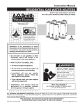
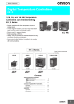
Front Panel
E5AZ
Temperature unit
No.1 display
Operation indicators
No.2 display
Up key
Level key
Mode key
Down key
E5EZ
Operation indicators
No.1 display
Temperature unit
No.2 display
Operation indicators
Mode key
Level key
1-1-2
Up key
Down key
Meaning of Indicators
No. 1 display
Displays the process value or parameter type.
Lights for approximately one second during startup.
No. 2 display
2
Displays the set point, parameter operation read value, or the variable input
value.
Section 1-1
Names of Parts
Lights for approximately one second during startup.
Operation indicators
1. ALM1 (alarm 1)
Lights when alarm 1 output is ON.
ALM2 (alarm 2)
Lights when alarm 2 output is ON.
ALM3 (alarm 3)
Lights when alarm 3 output is ON.
2. HB (heater burnout alarm display)
Lights when a heater burnout is detected.
3. OUT1, OUT2 (control output 1, control output 2)
Lights when control output 1 or control output 2 is ON.
However, OUT1 is not lit whenever control output 1 is current output.
4. STOP (stop)
Lights when operation is stopped.
During operation, this indicator lights when operation is stopped by an
event or by using the RUN/STOP function.
5. CMW (communications writing control)
Lights when communications writing is enabled and is not lit when it is disabled.
Temperature unit
The temperature unit is displayed when parameters are set to display a temperature. The display is determined by the currently selected "temperature
unit" parameter set value. c indicates °C and f indicates °F.
Flashes during ST operation.
1-1-3
Using the Keys
This section describes the basic functions of the front panel keys.
(level) key
Press this key to move between setting levels. The following setting levels can
be selected: operation level, adjustment level, initial setting level, communications setting level.
(mode) key
Press this key to change parameters within a setting level.
(up) key
Each press of this key increments the value displayed on the No. 2 display or
advances the setting. Holding the key down speeds up the incrementation.
(down) key
Each press of this key decrements values displayed on the No. 2 display or
reverses the setting. Holding the key down speeds up the decrementation.
+
These keys set the E5AZ/E5EZ to the "protect level". For details on the protect level, refer to SECTION 5 Parameters.
keys
3
Section 1-2
I/O Configuration and Main Functions
1-2
I/O Configuration and Main Functions
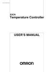
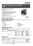
1-2-1
I/O Configuration
E5AZ/E5EZ
OUT1
Control output 1
Temperature
input/analog input
Control output 1
Control output 2
*
OUT2
Heating/
cooling
CT input
(See note.)
Alarm output 3
Standard
ALM3
*
Alarm 3
Event input 2ch
(See note.)
ALM2
Controller
Alarm 2
Set point input functions from
external digital switches:
Run/Stop
Alarm 1
*
HBA
Alarm output 2
ALM1
HB
Alarm output 1
Input error
*
Communications
function
*Items marked with asterisks are options.
Note
1-2-2
Functions can be assigned individually for each output by changing the set
values for the control output 1 assignment, the control output 2 assignment,
the alarm 1 assignment, the alarm 2 assignment, and the alarm 3 assignment
in the advanced function setting level.
Basic Model
E5@Z - @ 3 @ @
Option 2: Blank: Not available.
01:
RS-232C
03:
RS-485
B:
2 event inputs
Option 1: Blank: Not available.
H:
Heater Burnout Alarm
3:
Three alarms
Control Output: R: Relay Output
Q: Voltage Output
C: Current Output
A: Output Unit can be mounted.
Size:
Note
4
A:
E:
96 × 96 mm (W × H)
96 × 48 mm (W × H)
Options 1 and 2 are supported when using an E53-AZM Option Board.
I/O Configuration and Main Functions
1-2-3
Section 1-2
Main Functions
This section introduces the main E5AZ/E5EZ functions. For details on particular functions and how to use them, refer to SECTION 3 Basic Operation and
following sections.
Input Sensor Types
• The following input sensors can be connected for temperature input:
Platinum resistance thermometer
: Pt100, JPt100
Thermocouple
: K, J, T, E, L, U, N, R, S, B
Infrared temperature sensor: ES1B
:10 to 70°C, 60 to 120°C, 115 to 165°C,
140 to 260°C
Analog input
: 0 to 50 mV
Control Outputs
• A control output can be relay, voltage, or current output, depending on the
model of E5AZ/E5EZ.
• With the E5@Z-@3@@, alarm output 3 is used as control output 2 (cooling) when heating/cooling control is selected. Therefore, use alarm 1 and
2 if an alarm is required while using heating/cooling control.
Alarms
• Alarms can be used with the E5@Z-@3@@. Set the alarm type and alarm
value or the alarm value upper and lower limits.
• If necessary, a more comprehensive alarm function can be achieved by
setting the standby sequence, alarm hysteresis, close in alarm/open in
alarm, and alarm latch parameters.
• When the "input error output" parameter is set to ON, alarm output 1 turns
ON when an input error occurs.
Control Adjustment
• Optimum PID constants can be set easily by performing AT (auto-tuning)
or ST (self-tuning).
Event Inputs
• With the E53-AZB, the following functions can be executed using event
inputs: switching set points (multi-SP, 4 pts. max.), and switching RUN/
STOP status.
Heater Burnout Alarms
(HBA)
• With the E53-AZH, the heater burnout detection alarm function can be
used.
Communications
Functions
• With the E53-AZ01 or E53-AZ03, the communications functions utilizing
CompoWay/F (See note 1.) or SYSWAY can be used.
E5@Z-@3@03: RS-485 interface
E5@Z-@3@01: RS-232C interface
Note
1. CompoWay/F is an integrated general-purpose serial communications
protocol developed by OMRON. It uses commands compliant with the wellestablished FINS, together with a consistent frame format on OMRON Programmable Controllers to facilitate communications between personal
computers and components.
2. SYSWAY communications cannot be used for the alarm 3 output.
5
Section 1-3
Setting Level Configuration and Key Operations
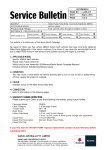
1-3
Setting Level Configuration and Key Operations
Parameters are divided into groups, each called a “level”. Each of the set values (setup items) in these levels are called a “parameter.” The parameters on
the E5AZ/E5EZ are divided into the following six levels:
Power ON
Operation level
Adjustment level
+
keys
The PV display
flashes
+
keys
1 second min.
key
Less than
1 second
key 3 seconds min.
key
1 second min.
25
100
key
The PV display flashes after one second.
25
100
+
keys
3 seconds min.
Control stops.
Initial setting level
key
Less than
1 second
key
1 second min.
Communications
setting level
Password input
set value "−169"
Advanced
function setting level
Protect level
Note :
Communications setting level is displayed
when the optional communications unit
E53-AZ01 or E53-AZ03 is mounted along
with the E53-AZM option board.
The key pressing time can be changed in
"Move to protect level time" (advanced
function setting level).
Control in progress
Control stopped
Note
Protect level
Control in
Progress
Can be set.
Control Stopped
-
Operation level
Adjustment level
Can be set.
Can be set.
-
Initial setting level
Advanced function setting level
(See note.)
Communications setting level
-
Can be set.
Can be set.
-
Can be set.
Set the parameters in the “initial setting/communications protect” under “protect level” to “0”, to activate advanced function setting level.
Of these levels, the initial setting level, communications setting level, and
advanced function setting level can be used only when control has stopped.
Note that controller outputs are stopped when any of these three levels are
selected.
6
Section 1-3
Setting Level Configuration and Key Operations
Protect level
• To move to this level, simultaneously press the
and
keys for at
least three seconds in the operation level or adjustment level. This level is
for preventing unwanted or accidental modification of parameters. Protected levels will not be displayed, and so the parameters in that level cannot be modified.
Note
Operation level
The key pressing time can be changed in "Move to protect level
time" (advanced function setting level).
• This level is displayed when you turn the power ON. You can move to the
protect level, initial setting level and adjustment level from this level.
• Normally, select this level during operation. During operation, the process
value and manipulated variable can be monitored, and the set points,
alarm values and upper- and lower-limit alarms can be monitored and
modified.
Adjustment level
• To move to this level, press the
key for less than one second.
• This level is for entering set values and offset values for control. This level
contains parameters for setting the AT (auto-tuning), communications
writing enable/disable, hysteresis, multi-SP, input shift values, heater
burnout alarm (HBA) and PID constants. You can move to the top parameter of the initial setting level, protect level, and operation level from here.
Initial setting level
• To move to this level, press the
key for at least three seconds in the
operation level or adjustment level. The PV display flashes after one second. This level is for specifying the input type, selecting the control
method, control period, setting direct/reverse operation and alarm type.
You can move to the advanced function setting level or communications
setting level from this level. To return to the operation level, press the
key for at least one second. To move to the communications setting level,
press the
key for less than one second.
Advanced function setting
level
• To activate this level, set the parameters in the “initial setting/communications protect” under the “protect level” to “0” and then enter the password
(“−169”) in the initial setting level.
• The initial setting level can be accessed from this level.
• This level is for setting the automatic display return time, MV limiter, event
input assignment, standby sequence, alarm hysteresis, and ST (self-tuning).
Communications setting
level
• To move to this level, press the
key for less than one second in the
initial setting level. When the communications function is used, set the
communications conditions in this level. Communicating with a personal
computer (host computer) allows set points to be read and written, and
manipulated variables to be monitored.
Note
This level is available if a communications unit (E53-AZ01 or E53AZ03) is fitted to the unit along with the E53-AZM option board.
7
Section 1-4
Communications Function
1-3-1
Selecting Parameters
• To select parameters in each level, press the
key. Each press of the
key advances to the next parameter. For details on each parameter,
see Section 5.
Parameter
1
Parameter
2
Parameter
3
Parameter
n
1-3-2
Fixing Settings
• If you press the
key at the final parameter, the display returns to the
top parameter for the current level.
• To change parameter settings or setup, specify the setting using the
or
the
key, and either leave the setting for at least two seconds or press
key. This fixes the setting.
• When another level is selected, the parameter and setting on the display
are fixed.
• When you turn the power OFF, you must first fix the settings or parameter
setup (by pressing the
key). The settings and parameter setup are
sometimes not changed by merely pressing the
1-4
or
key.
Communications Function
The E5AZ/E5EZ can be provided with a communications function that allows
you to check and set controller parameters on a host computer. If the communications function is required, mount the option unit E53-AZ01 or E53-AZ03 in
the E5AZ/E5EZ. For details on the communications function, see the separate
Communications User’s Manual (Cat. No. H204).
Follow the procedure below to move to the communications setting level.
1,2,3...
1. Press the
key for at least three seconds in the “operation level”. The
level moves to the “initial setting level”.
2. Press the
key for less than one second. The “initial setting level”
moves to the “communications setting level”.
8
Section 1-4
Communications Function
3. Pressing the
figure.
4. Press the
key advances the parameters as shown in the following
or
key to change the parameter setups.
Communications unit No.
Baud rate
Data length
Stop bits
Parity
Setting up
communications data
Parameter
Set the E5AZ/E5EZ communications specifications so that they match the
communications setup of the host computer.
Displayed
Characters
Set (monitor) Value
Communications unit No.
Baud rate
u-no 0 to 99
bps 1.2, 2.4, 4.8, 9.6, 19.2
Data length
Stop bits
len 7, 8
sbit 1, 2
Parity
prty None, even, odd
Settings
1. 2, 2. 4, 4. 8, 9. 6,
19. 2
none, even, odd
Default
Unit
1
9.6
None
kbps
7
2
bit
bit
Even
None
9
Communications Function
10
Section 1-4
SECTION 2
Preparations
This section describes the work required to prepare the E5AZ/E5EZ Digital Temperature Controllers for operation,
including installation and wiring.
2-1
2-2
2-3
Installation. . . . . . . . . . . . . . . . . . . . . . . . . . . . . . . . . . . . . . . . . . . . . . . . . . . .
12
2-1-1
Dimensions . . . . . . . . . . . . . . . . . . . . . . . . . . . . . . . . . . . . . . . . . . . .
12
2-1-2
Panel Cutout . . . . . . . . . . . . . . . . . . . . . . . . . . . . . . . . . . . . . . . . . . .
13
2-1-3
Mounting. . . . . . . . . . . . . . . . . . . . . . . . . . . . . . . . . . . . . . . . . . . . . .
14
2-1-4
Setting up the Option Units . . . . . . . . . . . . . . . . . . . . . . . . . . . . . . .
15
Wiring Terminals. . . . . . . . . . . . . . . . . . . . . . . . . . . . . . . . . . . . . . . . . . . . . . .
16
2-2-1
Terminal Arrangement . . . . . . . . . . . . . . . . . . . . . . . . . . . . . . . . . . .
16
2-2-2
Precautions when Wiring . . . . . . . . . . . . . . . . . . . . . . . . . . . . . . . . .
18
2-2-3
Wiring . . . . . . . . . . . . . . . . . . . . . . . . . . . . . . . . . . . . . . . . . . . . . . . .
18
Requests at Installation . . . . . . . . . . . . . . . . . . . . . . . . . . . . . . . . . . . . . . . . . .
22
2-3-1
To Ensure Prolonged Use . . . . . . . . . . . . . . . . . . . . . . . . . . . . . . . . .
22
2-3-2
To Reduce the Influence of Noise. . . . . . . . . . . . . . . . . . . . . . . . . . .
22
2-3-3
To Ensure High-precision Measurement . . . . . . . . . . . . . . . . . . . . .
22
11
Section 2-1
Installation
2-1
2-1-1
E5AZ
Installation
Dimensions
(Unit: mm)
11.5
91
91
E5EZ
(Unit: mm)
11.5
12
Section 2-1
Installation
E5AZ
Panel Cutout
(Unit: mm)
Individual Mounting
Group Mounting
(96 × number of Units − 3.5) +1.0
92+0.8
0
120 min.
92+0.8
0
0
92+0.8
0
2-1-2
(Unit: mm)
Individual Mounting
Group Mounting
92+0.8
0
45+0.6
0
92+0.8
0
(48 × number of Units − 2.5) +1.0
0
120 min.
E5EZ
• The recommended panel thickness is 1 to 8 mm.
• Units must not be closely mounted vertically. (Observe the recommended
mounting space limits.)
• When group mounting several Controllers, ensure that the surrounding
temperature does not exceed the ambient operating temperature listed in
the specifications.
13
Section 2-1
Installation
2-1-3
Mounting
E5AZ
Adapter mounted (sold separately).
E5
AZ
E5EZ
Adapter mounted (sold separately).
E5
EZ
Mounting to the Panel
1,2,3...
14
1. Insert the E5AZ/E5EZ into the square mounting hole in the panel (thickness: 1 to 8 mm). Attach the Mounting Brackets provided with the product
to the mounting grooves on the top and bottom surfaces of the rear case.
Section 2-1
Installation
2. Use a ratchet to alternately tighten the screws on the top and bottom
Mounting Brackets little by little to maintain balance, until the ratchet turns
freely.
2-1-4
Setting up the Option Units
If heater burnout alarm, communications and event input functions are
required, mount a heater burnout alarm unit (E53-AZH), a communications
unit (E53-AZ01 or E53-AZ03), or an event input unit (E53-AZB).
The E5AZ/E5EZ provides optional functions when an E53-AZM option board
is mounted along with one or two (E53-AZH and another) option units.
Option units
Name
Model
Function
Option Board
Heater Burnout Alarm Unit
E53-AZM
E53-AZH
Option board is mounted along with one or two of the following option units.
Heater burnout alarm
Communications Unit
E53-AZ01
E53-AZ03
RS-232C communications
RS-485 communications
Event Input Unit
E53-AZB
Event input
• Terminal label: × 1
Assembling the unit
(1)
Flat-blade
screwdriver
(units: mm)
20 min.
(4)
(2)
0.4 2.0
(1)
(3)
1,2,3...
1. Insert the tools (see drawing above) into the slots (one on the top and one
on the bottom) and release the hooks.
2. Insert the tool into the gap between the front and rear, and slightly draw out
the front panel. Then, draw out the front panel towards you holding it by its
top and bottom sides.
3. Match the upper and lower claws with the connection points and insert the
option board (E53-AZM) after the option unit (E53-AZH, E53-AZ01, E53AZ03, or E53-AZB) is attached to the board. Mount the option board in the
left from the front.
4. Before you push the unit back into the case, make sure that the packing is
in place. Push the unit back into the rear case until you hear a click. When
you do this, hold down the hooks on the top and bottom of the rear case so
that they are firmly hooked in place.
15
Section 2-2
Wiring Terminals
2-2
2-2-1
Wiring Terminals
Terminal Arrangement
E5AZ
100 to 240 VAC
1
1
12
2
2
13
3
3
14
Input power supply
AL3/OUT2
Alarm output, 250 VAC 2 A
(resistive load)
4
4
15
5
5
16
6
6
17
7
7
18
8
8
19
AL2
Voltage output, 12 VDC 40 mA
AL1/HB
Current output, 4 to 20 mA DC
600 Ω
OUT1
A
Relay output, 250 VAC 5 A
(resistive load)
−
−
B
B
+
+
Analog input TC
9
9
20
10
10
21
11
11
22
Pt
E5EZ
100 to 240 VAC
1
Input power supply
2
AL3/OUT2
Alarm output, 250 VAC 2 A
(resistive load)
AL2
3
4
5
Voltage output, 12 VDC 40 mA
6
AL1/HB
7
Current output, 4 to 20 mA DC
600 Ω
OUT1
8
A
9
Relay output, 250 VAC 5 A
(resistive load)
−
−
B
B
+
+
Analog input TC
16
10
11
Pt
Section 2-2
Wiring Terminals
Option Units
E53-AZM
Option Board
E53-AZ@ or E53-AZ@@
Option Units
12
13
A
+
14
15
Contact inputs
E53-AZ01
Communications
E53-AZ03
Communications
RS-232C
Non-contact inputs
RS-485
SD
12
B (+)
RD
13
SG
14
The E53-AZM option board is always
mounted along with one or two (E53AZH and another) option units.
A (−)
Do not use.
15
Do not use.
Do not use.
Do not use.
16
Do not use.
Do not use.
Do not use.
B
E53-AZH
Heater Burnout Detection
12
Do not use.
13
Do not use.
14
Do not use.
15
16
Host computer
E53-AZB
Even Inputs
Host computer
A
Note
B
16
Heater burnout detection input
Note
The combination of A and B is also available.
17
Section 2-2
Wiring Terminals
2-2-2
Precautions when Wiring
• Separate input leads and power lines in order to protect the E5AZ/E5EZ
and its lines from external noise.
• Use AWG24 (cross-sectional area: 0.205 mm2) to AWG14 (cross-sectional area: 2.081 mm2) twisted-pair cable (stripping length: 5 to 6 mm).
Cross-sectional area of conductor
2
AWG24: 0.205 mm
2
AWG14: 2.081 mm
• We recommend using solderless terminals when wiring the E5AZ/E5EZ.
• Tighten the terminal screws using a torque no greater than 0.74 to
0.90 N⋅m.
• Use the following type of solderless terminals for M3.5 screws.
7.2 mm max.
7.2 mm max.
2-2-3
Wiring
Power supply
• Connect to terminals 1 and 2. The following table shows the specifications.
Input power supply
E5AZ/E5EZ
100 to 240 VAC, 50/60 Hz
10 VA
• Reinforced insulation is applied between the input power supply and the
I/O sections.
Input
• Connect to terminals 9 to 11 as follows according to the input type.
A
B
10
B’
11
Thermocouple
Control output 1
9
10
Platinum
resistance
thermometer
11
Analog
input
• Terminals 7 and 8 are for control output. The following diagrams show the
available outputs and their internal equalizing circuits.
+
7
8
7
+V
L
−
Relay
+
+V
7
L
18
10
V
11
8
GND
Voltage
−
8
GND
Current
Section 2-2
Wiring Terminals
• The following table shows the specifications for each output type.
Output type
Relay
Specifications
250 VAC, 5 A (resistive load), electrical life: 100,000 operations
Voltage (PNP)
Current
PNP type, 12 VDC, 40 mA (with short-circuit protection)
4 to 20 mA DC, load: 600 Ω max., resolution: approx. 2,600
• The voltage output (control output) is not electrically insulated from the
internal circuits. When using a grounding thermocouple, do not connect
the control output terminals to the ground. If the control output terminals
are connected to the ground, errors will occur in the measured temperature values as a result of leakage current.
Alarm output/Control
output 2
• On the E5@Z-@3@@, alarm output 1 (ALM1) is across terminals 5 and 6,
and alarm output 2 (ALM2) is across terminals 4 and 6, and alarm output
3 (ALM3) is across terminals 3 and 6. When heating/cooling control is
used, alarm output 3 becomes cooling output.
When the input error output is set to “ON”, alarm output 1 turns ON when
an input error occurs.
• Terminals 5 and 6 on the E5AZ/E5EZ to which an E53-AZH Option Unit is
mounted output the alarm output 1 or heater burnout alarm values. If the
mode of alarm output 1 is set to 0 to disable alarm output 1, terminals 5
and 6 will output the heater burnout alarm.
• The equivalent circuits of alarm output 1, 2, and 3 are shown in the following diagram.
3
4
AL3/OUT2
5
AL2
AL1/HB
6
• Relay specifications are as follows:
SPST-NO 250 VAC 2 A
CT input
• When the option unit (E53-AZH) is mounted on the E5AZ/E5EZ and the
heater burnout function is used, connect a current transformer (CT)
across terminals 15 and 16.
15
CT
16
Event input
• When the option event input unit E53-AZB is mounted in the E5AZ/E5EZ
and event input is used, connect to terminals 12 to 14.
12
+
EV1
+
EV2
13
14
−
• Use event inputs under the following conditions:
19
Section 2-2
Wiring Terminals
• The output current is approx. 7 mA.
Contact input ON: 1 kΩ max., OFF: 100 kΩ min.
No-contact input ON: residual voltage 1.5 V max., OFF: leakage current 0.1 mA max.
Polarities during no-contact input are as follows:
12
EV1
13
EV2
14
RS-232C
Communications
• When the E53-AZ01 option communications unit is mounted in the E5AZ/
E5EZ for communicating with a host computer, connect the communications cable across terminals 12, 13, and 14.
12
13
14
SD
RD
RS-232C
SG
Communications Unit Wiring Diagram
Host computer
RS-232C: 25 Pin
RS-232C
No.
SD(TXD)
2
12
SD
RD(RXD)
3
13
RD
RS(RTS)
4
14
SG
CS(CTS)
5
DR(DSR)
6
SG
ER(DTR)
FG
7
20
1
• The RS-232C connection is 1:1.
• The maximum cable length is 15 m. Use the RS-232C optical interface
cable (Z3RN) as an extension cable if necessary.
• Use AWG24 (cross-sectional area: 0.205 mm2) to AWG14 (cross-sectional area: 2.081 mm2) shielded twisted-pair cable.
RS-485
Communications
• When the E53-AZ03 option communications unit is mounted in the E5AZ/
E5EZ for communicating with a host computer, connect the communications cable across terminals 12 and 13.
Specify both ends of the transmission path including the host computer as
the end node (that is, connect terminators to both ends).
The maximum terminal resistance is 54 Ω.
12
B(+)
13
A(−)
RS-485
20
Section 2-2
Wiring Terminals
• To satisfy the requirements of the EN 61326 class A standard in the conducted emission test, add a clamp filter (TDK: ZAT1730-0730) in the communications line between the K3SC and the Temperature Controller.
Communications Unit Wiring Diagram
Host computer
Shielded cable
RS-485
−
+
FG
A<B: "1" mark
A>B: "0" space
E5AZ/E5EZ (No.1)
RS-485
No Abbr.
13 A(−)
12 B(+)
E5AZ/E5EZ (No.31)
RS-485
No Abbr.
13 A(−)
12 B(+)
Terminator (120 Ω, 1/2 W)
• The RS-485 connection can be either one-to-one to one-to-N. Up to
32 units including the host computer can be connected in one-to-N systems. Use AWG24 (cross-sectional area: 0.205 mm2) to AWG14 (crosssectional area: 2.081 mm2) shielded twisted-pair cable and keep the total
cable length to 500 m.
Cable reference diagram
Cross-sectional area of conductor
2
AWG24: 0.205 mm
2
AWG14: 2.081 mm
21
Section 2-3
Requests at Installation
2-3
2-3-1
Requests at Installation
To Ensure Prolonged Use
Use the temperature in the following operating environment:
Temperature: –10 to +55°C (icing and condensation not allowed)
Humidity: 25 to 85%
When the temperature controller is incorporated in a control panel, make sure
that the controller’s ambient temperature and not the panel’s ambient temperature does not exceed 55°C.
The life of electronic equipment such as temperature controllers is influenced
not only by the life determined by the relay switching count but also by the life
of the electronic components used internally. The service life of components
is dependent on the ambient temperature: the higher the ambient temperature
becomes, the shorter the service life becomes, and vice versa. For this reason, the service life of the temperature controller can be extended by lowering
its internal temperature.
Gang-mounting two or more temperature controllers, or mounting temperature controllers above each other may cause heat to build up inside the temperature controllers, which will shorten their service life. When mounting
temperature controllers like this, forced cooling measures such as a cooling
fan for cooling the temperature controllers must be taken into consideration.
Prevent only the terminal block from being cooled. Otherwise, this may result
in a measurement error.
2-3-2
To Reduce the Influence of Noise
To reduce induction noise, the leads on the temperature controller’s terminal
block must be wired separately from large-voltage/large-current power leads.
Also, avoid wiring leads in parallel with power leads or in the same wiring
path. Other methods such as separating conduits and wiring ducts, or using
shield wire are also effective.
Attach a surge absorber or noise filter to peripheral equipment that generates
noise (in particular, motors, transformers, solenoids, or other equipment that
has a magnetic coil or other inductance component).
When a noise filter is used at the power supply, first check the voltage or current, and attach the noise filter as close as possible to the temperature controller.
Also, install the temperature controller as far away as possible from equipment
that generates strong, high frequency (e.g. high-frequency welders, high-frequency sewing machines) or surges.
2-3-3
To Ensure High-precision Measurement
When the thermocouple leads are extended, be sure to use a compensating
lead wire matched to the type of thermocouple.
When the platinum resistance detector leads are extended, use the lead having the smallest resistance to equalize the resistance of the three leads.
Install the temperature controller so that it is horizontal.
If there is a large error in the measurement values, make sure that input compensation has been set correctly.
22
SECTION 3
Basic Operation
This section describes the basic operation of the E5AZ/E5EZ Digital Temperature Controllers, including key operations to
set parameters and descriptions of display elements based on specific control examples.
3-1
3-2
3-3
Initial Setting Examples . . . . . . . . . . . . . . . . . . . . . . . . . . . . . . . . . . . . . . . . .
24
Setting the Input Type . . . . . . . . . . . . . . . . . . . . . . . . . . . . . . . . . . . . . . . . . . .
27
3-2-1
Input Type . . . . . . . . . . . . . . . . . . . . . . . . . . . . . . . . . . . . . . . . . . . . .
27
Selecting the Temperature Unit. . . . . . . . . . . . . . . . . . . . . . . . . . . . . . . . . . . .
28
3-3-1
28
Temperature Unit . . . . . . . . . . . . . . . . . . . . . . . . . . . . . . . . . . . . . . .
3-4
Selecting PID Control or ON/OFF Control . . . . . . . . . . . . . . . . . . . . . . . . . .
29
3-5
Setting Output Specifications . . . . . . . . . . . . . . . . . . . . . . . . . . . . . . . . . . . . .
30
3-5-1
Control Period. . . . . . . . . . . . . . . . . . . . . . . . . . . . . . . . . . . . . . . . . .
30
3-5-2
Direct/Reverse Operation . . . . . . . . . . . . . . . . . . . . . . . . . . . . . . . . .
30
3-6
3-7
3-8
3-9
Setting the Set Point (SP) . . . . . . . . . . . . . . . . . . . . . . . . . . . . . . . . . . . . . . . .
32
3-6-1
Changing the SP . . . . . . . . . . . . . . . . . . . . . . . . . . . . . . . . . . . . . . . .
32
Using ON/OFF Control. . . . . . . . . . . . . . . . . . . . . . . . . . . . . . . . . . . . . . . . . .
33
3-7-1
ON/OFF Control. . . . . . . . . . . . . . . . . . . . . . . . . . . . . . . . . . . . . . . .
33
3-7-2
Settings . . . . . . . . . . . . . . . . . . . . . . . . . . . . . . . . . . . . . . . . . . . . . . .
34
Determining PID Constants (AT, ST, Manual Setup) . . . . . . . . . . . . . . . . . . .
35
3-8-1
AT (Auto-tuning) . . . . . . . . . . . . . . . . . . . . . . . . . . . . . . . . . . . . . . .
35
3-8-2
ST (Self-tuning) . . . . . . . . . . . . . . . . . . . . . . . . . . . . . . . . . . . . . . . .
37
3-8-3
ST Start Conditions. . . . . . . . . . . . . . . . . . . . . . . . . . . . . . . . . . . . . .
37
3-8-4
ST Stable Range . . . . . . . . . . . . . . . . . . . . . . . . . . . . . . . . . . . . . . . .
38
3-8-5
Manual Setup . . . . . . . . . . . . . . . . . . . . . . . . . . . . . . . . . . . . . . . . . .
38
Alarm Outputs. . . . . . . . . . . . . . . . . . . . . . . . . . . . . . . . . . . . . . . . . . . . . . . . .
40
3-9-1
Alarm Types . . . . . . . . . . . . . . . . . . . . . . . . . . . . . . . . . . . . . . . . . . .
41
3-9-2
Alarm Values . . . . . . . . . . . . . . . . . . . . . . . . . . . . . . . . . . . . . . . . . .
42
3-9-3
Alarm Delays . . . . . . . . . . . . . . . . . . . . . . . . . . . . . . . . . . . . . . . . . .
43
3-10 Using Heater Burnout Alarm (HBA) . . . . . . . . . . . . . . . . . . . . . . . . . . . . . . .
45
3-10-1 HBA Detection . . . . . . . . . . . . . . . . . . . . . . . . . . . . . . . . . . . . . . . . .
45
3-10-2 Operating Conditions . . . . . . . . . . . . . . . . . . . . . . . . . . . . . . . . . . . .
45
3-10-3 Setup . . . . . . . . . . . . . . . . . . . . . . . . . . . . . . . . . . . . . . . . . . . . . . . . .
46
3-10-4 Calculating Detection Current Values . . . . . . . . . . . . . . . . . . . . . . .
48
3-10-5 Application Examples. . . . . . . . . . . . . . . . . . . . . . . . . . . . . . . . . . . .
48
3-11 Requests during Operation . . . . . . . . . . . . . . . . . . . . . . . . . . . . . . . . . . . . . . .
49
23
Section 3-1
Initial Setting Examples
3-1
Initial Setting Examples
On previous controllers, sensor input type, alarm type and control period were
set by the DIP switches. These hardware settings are now set in parameters
in setup menus. The
and
keys are used to switch between setup
menus, and the amount of time that you hold the keys down for determines
which setup menu you move to. This section describes two typical examples.
Interpretations and Meanings
of Typical Examples
Changing Setting Value
in-t
0
Indicates the continued presence of set data.
This should be pressed
continuously prior
to switching to any other data objectives.
in-h
100
in-l
0
cntl
onof
24
Changing Numeric Value
C
cntl
onof
25
0
Each interface’ value and their selection
are realized through UD this option.
Section 3-1
Initial Setting Examples
Typical example 1
Input type:
Control method:
Alarm type:
Alarm value 1:
Set point:
5 K thermocouple −200 to 1300°C
ON/OFF control
2 upper limit
20°C (deviation)
100°C
Setup procedure
Power ON
Power ON
Operation level
25 Process value/
25
C
0
0
set point
Press
key for at least
three seconds.
Control stops.
Initial setting level
Initial setting level
Set input
specifications
Set control
specifications
Set alarm type
in-t
in-t
Check input
type.
5
5
Check that
control is
ON/OFF control.
cntl
cntl
onof
onof
alt1
alt1
Check alarm
type.
22
Input type
5
In ON/OFF
control in
PID control
onof
pid
Alarm 1 type 2
Press
key for at
at least one second.
Operation level
Press
keys
to set point to
"100°C".
Operation level
Set alarm values
Start operation
C
25
25
100
100
Make sure that
control is
running.
run
During run run
During stop stop
al-1
al-1
Alarm value 1 20
r-5
r-5
run
Press
keys
to set alarm
value to "20°C".
C
Process value/
set point 100
20
20
Start operation
25
Section 3-1
Initial Setting Examples
Typical example 2
Input type:
9 T thermocouple −200 to 400°C
Control method:
PID control
Calculate PID constants by AT (auto-tuning)
execution.
Alarm type:
2 upper limit
Alarm value 1:
30°C (deviation)
Set point:
150°C
Setup procedure
Power ON
Power ON
Operation level
C
25 Process value/
25
0
0 set point
Press
key for at
least three seconds.
Control stops.
Initial setting level
Initial setting level
Set input
specifications
Set control
specifications
Set alarm type
Press DU keys
to select input
type.
in-t
in-t
Press DU keys
to set PID control.
cntl
cntl
9
C
25
150
In ON/OFF onoff
control
pid
pid In PID control
Press DU keys
to set ST to OFF.
st
st
To execute ST on
Check the
control period.
cp
cp
Control period
(heat) (unit:
seconds) 20
off To cancel ST off
off
20
20
alt1
alt1
Adjustment level
AT execution
26
150
While AT is being
executed, SP will flash
After AT execution
2
Adjustment level
Execute AT
(auto-tuning).
2
Alarm 1 type 2
Press
key for at
least one second.
Operation level
Press DU keys
to set point to
"150°C".
During AT execution
C
Input type 9
pid
Check alarm
type.
PV/SP
After AT execution
9
C
25
25
150
150
Process value/
set point 150
Press
key for
less than 1 second.
at
at
To execute AT on
off
To cancel AT off
off
at
(when PID
control is
selected)
off
During AT execution
at
on
Operation level
Make sure
that set point
is "150°C".
Make sure that
control is
running.
Press
key for
less than 1 second.
25
25
150
Process value/
150 set point 150
r-5
r-5
During run run
run
run During stop stop
Operation level
Set alarm values
Start operation
26
Press DU keys
to set alarm value
to "30°C".
al-1
al-1
30
30
Alarm value 1 30
Start program execution
Section 3-2
Setting the Input Type
3-2
Setting the Input Type
The E5AZ/E5EZ supports four input types: platinum resistance thermometer,
thermocouple, infrared temperature sensor and analog inputs. Set the input
type matched to the sensor used in the “input type” parameter. In the product
specifications, there are models with thermocouple/resistance thermometer
inputs (multi-input) and models with analog input. The settings differ depending on the model. Check to make sure which model you are using.
3-2-1
Input Type
Setting the input type “thermocouple K −20.0 to 500.0°C”.
Operation Procedure
Operation level
C
1,2,3...
25
1. Press the
key for at least three seconds to move from the “operation
level” to the “initial setting level”.
0
Initial setting level
in-t
Input type
2. Press the
key to enter the set value of the desired sensor. When you
use K thermocouple (−20.0 to 500.0°C), enter “6” as the set value.
Hint:
5
The set value is fixed if you do not operate the keys on the front panel
for two seconds after changing the parameter, or by pressing the
or
key.
List of Input Types
in-t
Input type
6
Platinum resistance
thermometer
Thermocouple
Name
Pt100
−200 to 850 (°C)/−300 to 1500 (°F)
1
−199.9 to 500.0 (°C)/−199.9 to 900.0 (°F)
0.0 to 100.0 (°C)/0.0 to 210.0 (°F)
3
−199.9 to 500.0 (°C)/−199.9 to 900.0 (°F)
4
0.0 to 100.0 (°C)/0.0 to 210.0 (°F)
K
5
−200 to 1300 (°C)/−300 to 2300 (°F)
6
−20.0 to 500.0 (°C)/0.0 to 900.0 (°F)
7
−100 to 850 (°C)/−100 to 1500 (°F)
8
−20.0 to 400.0 (°C)/0.0 to 750.0 (°F)
9
−200 to 400 (°C)/−300 to 700 (°F)
22
−199.9 to 400.0 (°C)/ −199.9 to 700.0 (°F)
10
0 to 600 (°C)/ 0 to 1100 (°F)
L
11
−100 to 850 (°C)/−100 to 1500 (°F)
U
12
−200 to 400 (°C)/−300 to 700 (°F)
23
−199.9 to 400.0 (°C)/−199.9 to 700.0 (°F)
E
Note
0
JPt100
T
Analog input
Input Temperature Setting Range
2
J
Infrared temperature
sensor
ES1B
Set
Value
N
13
−200 to 1300 (°C)/−300 to 2300 (°F)
R
14
0 to 1700 (°C)/0 to 3000 (°F)
S
15
0 to 1700 (°C)/0 to 3000 (°F)
B
16
100 to 1800 (°C)/ 300 to 3200 (°F)
10 to 70°C
17
0 to 90 (°C)/0 to 190 (°F)
60 to 120°C
18
0 to 120 (°C)/0 to 240 (°F)
115 to 165°C
19
0 to 165 (°C)/0 to 320 (°F)
140 to 260°C
20
0 to 260 (°C)/0 to 500 (°F)
0 to 50mV
21
One of the following ranges depending on the
results of scaling:
−1999 to 9999, −199.9 to 999.9,
The default is “5”.
27
Section 3-3
Selecting the Temperature Unit
3-3
Selecting the Temperature Unit
3-3-1
Temperature Unit
• Select either “°C” or “°F” as the temperature unit.
• Set the temperature unit in the “temperature unit” parameter of “initial setting level”. Default is “c: °C”.
Select “°C”.
Operation Procedure
Operation level
C
1,2,3...
30
1. Press the
key for at least three seconds to move from the “operation
level” to the “initial setting level”.
0
Initial setting level
in-t
Input type
Press the
c : °C
5
Temperature unit
d-u
c
28
2. Select the “temperature unit” parameter by pressing the
or
key.
key to select either “°C” or “°F”.
f : °F
3. To return to the “operation level” press the
key for at least one second.
Selecting PID Control or ON/OFF Control
3-4
Section 3-4
Selecting PID Control or ON/OFF Control
The E5AZ/E5EZ supports two control methods, 2-PID control and ON/OFF
control. The control method is selected by the “PID ON/OFF” parameter in the
“initial setting level”. When this parameter is set to “pid”, 2-PID control is set,
and when set to “onof”, ON/OFF control is set (default).
2-PID control
PID control is set by AT (auto-tuning), ST (self-tuning) or manual setup.
For PID control, set the PID constants in the “proportional band (P)”, “integral
time (I)” and “derivative time (D)” parameters.
ON/OFF control
In “ON/OFF” control, the control output is turned ON when the process value
is lower than the current set point, and the control output is turned OFF when
the process value is higher than the current set point (reverse operation).
29
Section 3-5
Setting Output Specifications
3-5
Setting Output Specifications
3-5-1
Control Period
Control
period
(OUT1)
Control
period
(OUT2)
• Set the output period (control period). Though a shorter period provides
better control performance, we recommend setting the control period to
20 seconds or more taking the life expectancy in the case of relay output
into consideration. If necessary, readjust the control period by trial operation, for example, when the control period parameters are set to their
defaults.
• Set the control period in the “control period (OUT1)” and “control period
(OUT2)” parameters (initial setting level). Default is “20 seconds”.
• The “control period (OUT2)” parameter can be used only in heating/cooling control.
• Whenever control output 1 is the current output, “control period (OUT1)”
cannot be used.
3-5-2
Direct/Reverse Operation
• “Direct operation” refers to control where the manipulated variable is
increased according to the increase in the process value. Alternatively,
“Reverse operation” refers to control where the manipulated variable is
decreased according to the increase in the process value.
Manipulated variable
Manipulated variable
100%
100%
0%
0%
Low temperature Set value
Direct operation
High temperature
Low temperature Set value
High temperature
Reverse operation
For example, when the process value (PV) (temperature) is lower than the set
point (SP) (temperature) in a heating control system, the manipulated variable
increases by the difference between the PV and SP values.
Accordingly, this becomes “reverse operation” in a heating control system, or
alternatively, “direct operation” in a cooling control system.
• Direct/reverse operation is set in the “direct/reverse operation” parameter
(initial setting level). The “direct/reverse operation” parameter default is
“reverse operation”.
30
Section 3-5
Setting Output Specifications
In this example, let’s monitor the “input type”, “temperature unit”, “direct/
reverse operation” and “control period (OUT1)” parameters.
Operation Procedure
“input type” = “5”: K thermocouple
“temperature unit” = “c”: °C
“direct/reverse operation” = “or-r”: reverse operation
“control period (OUT1)” = “20 (secs)”
Operation level
C
1,2,3...
30
1. Press the
key for at least three seconds to move from the “operation
level” to the “initial setting level”.
0
Initial setting level
in-t
Input type
5
d-u
2. The input type is displayed. When you are setting the input type for the first
time, “5”: K thermocouple is set. To select a different sensor, press the
or
Temperature unit
key.
3. Select the “temperature unit” parameter by pressing the
is “c”: °C. To select “f”: °F, press the
key. Default
key.
c
cp
Control period
(OUT1)
4. Select the “control period (OUT1) parameter by pressing the
Default is “20”.
key.
20
C
oreV
Direct/reverse
operation
5. Select the “direct/reverse operation” parameter by pressing the
key.
Default is “or-r”: reverse operation. To select “or-d”: direct operation,
press the
key.
PV/SP
6. To return to the “operation level”, press the
ond.
OOor-r
Operation level
C
30
key for at least one sec-
0
31
Section 3-6
Setting the Set Point (SP)
3-6
Setting the Set Point (SP)
The “operation level” is displayed when the E5AZ/E5EZ is turned ON. The
upper display (No.1 display) displays the process value, and the lower display
(No.2 display) displays the set point.
Operation level
C
20
0
3-6-1
Changing the SP
• The set point cannot be changed when the “operation/adjustment protect”
parameter is set to “3”. For details, see 4-9 Using the Key Protect Level.
• To change the set point, press the
or
key in the “PV/SP” param-
eter (operation level), and set the desired set value. The new set point is
selected two seconds after you have specified the new value.
• Multi-SP is used to switch between two or four set points.
See 4-5 Using Event Inputs for details.
In this example, let’s change the set point from “0°C” to “200°C”.
Operation Procedure
1,2,3...
Operation level
C
30
0
C
30
200
32
1. Normally, the “PV/SP” parameter is displayed. The set point is “0°C”.
2. Press the
key until the set point changes to “200°C”.
Section 3-7
Using ON/OFF Control
3-7
Using ON/OFF Control
In “ON/OFF” control, the control output turns OFF when the currently controlled temperature reaches a preset set point. When the manipulated variable
turns OFF, the temperature begins to fall and the control turns ON again. This
operation is repeated at a certain point. At this time, how much the temperature must fall before control turns ON again is determined by the “hysteresis
(OUT1)” parameter. Also, how much the manipulated variable must be
adjusted in response in the increase or decrease in the process value is
determined by “direct/reverse operation” parameter.
3-7-1
ON/OFF Control
• Switching between 2-PID control and ON/OFF control is carried out by the
“PID ON/OFF” parameter (initial setting level). When this parameter is set
to “pid”, 2-PID control is selected, and when set to “onof”, ON/OFF control is selected. Default is “onof”.
Hysteresis
• With ON/OFF control, hysteresis is used to stabilize operation when
switching between ON and OFF.
The control output (OUT1) and control output (OUT2) functions are set in
the hysteresis (OUT1) and hysteresis (OUT2) functions respectively.
• In standard control (heating or cooling control), the setting of the “hysteresis (heating)” parameter in the adjustment level is used as the hysteresis
regardless of whether the control type is heating control or cooling control.
Hysteresis (OUT1)
Revers operation
ON
OFF
PV
Set point
3-position control
• In heating/cooling control, a dead band (an area where both control outputs are “0”) can be set to either the heating or cooling side. This makes it
possible to use 3-position control.
Dead band
Revers operation
Hysteresis (OUT2)
Hysteresis (OUT1)
ON
Heating
side
Cooling
side
OFF
PV
Set point
Parameters
Symbol
Parameter Name: Level
Description
s-hc
Standard or heating/cooling: Initial setting level
For specifying control method
cntl
PID ON/OFF: Initial setting level
For specifying control method
orev
Direct/reverse operation: Initial setting level
For specifying control method
c-sc
Cooling coefficient: Adjustment level
Heating/cooling control
c-db
Dead band: Adjustment level
Heating/cooling control
hys
Hysteresis (OUT1): Adjustment level
ON/OFF control
chys
Hysteresis (OUT2): Adjustment level
ON/OFF control
33
Section 3-7
Using ON/OFF Control
3-7-2
Settings
To execute ON/OFF control, set the “set point,” “PID ON/OFF” and “hysteresis” parameters.
Setting the PID ON/OFF parameter
In this example, let’s first check that the “PID ON/OFF” parameter is set to
“onof” in the “initial setting level”.
Operation Procedure
1,2,3...
Operation level
C
PV
25
1. Press the
key for at least three seconds to move from the “operation
level” to the “initial setting level”.
100
Initial setting level
in-t
Input type
2. Display the “input type” parameter in the initial setting level.
PID ON/OFF
3. Select the “PID ON/OFF” parameter by pressing the
5
cntl
key.
4. Check that the set value is “onof” (default).
onof
5. Press the
key for at least 1 second to return to the “operation level”.
SP Setting
Next, set the set point value.
Operation Procedure
In this example, the set point is set to 200. The set value (i.e., the SP) is
shown at the bottom of the display.
1,2,3...
Operation level
C
25
100
C
25
200
34
PV/SP
1. In the operation level, select “PV/SP”.
2. Use the
the
key to set the SP value (for example: 200). After pressing
key or waiting for at least two seconds, this value will be fixed.
Section 3-8
Determining PID Constants (AT, ST, Manual Setup)
3-8
3-8-1
Determining PID Constants (AT, ST, Manual Setup)
AT (Auto-tuning)
• When you execute auto-tuning, the optimum PID constants for the set
point during program execution are automatically set by forcibly changing
the manipulated variable to calculate the characteristics (called the “limit
cycle method”) of the control target.
• To execute AT (auto-tuning), specify “on: AT execute”, and to cancel AT
(auto-tuning), specify “off: AT cancel”.
• AT (auto-tuning) cannot be executed when control has stopped or during
ON/OFF control.
• The result of AT (auto-tuning) is reflected in the “proportional band (P),”
“integral time (I)” and “derivative time (D)” parameters in the “adjustment
level”.
Adjustment level
C
p
Proportional band
i
Integral time
8.0
233
d
Derivative time
40
AT Operations
AT (auto-tuning) is started when the “AT execute/cancel” parameter is set to
“ON”. During execution of AT, the No.1 display for the “AT execute/cancel”
parameter blinks. When AT ends, the “AT execute/cancel” parameter turns
OFF, and the No.1 display stops blinking.
AT execute/cancel
at
at
off
No.1 display
on
During AT execution
If you move to the “operation level” during AT execution, the No.2 display
blinks to indicate that AT is being executed.
PV/SP
C
25
100
C
25
No.2 display
100
During AT execution
Only the “communications writing”, “run/stop” and “AT execute/cancel” parameters can be changed during AT execution. Other parameters cannot be
changed.
35
Section 3-8
Determining PID Constants (AT, ST, Manual Setup)
Execute auto-tuning (AT).
Operation Procedure
1,2,3...
Adjustment Level
AT execute/
cancel
1. Press the
key for less than one second to move from the “operation
level” to the “adjustment level”.
2. Press the
key to start execution of AT (auto-tuning).
“on” is displayed during AT execution.
3. “off” is displayed when AT ends.
Operation level
PV
About PID parameters
36
4. To return to the “operation level,” press the
key.
When control characteristics are already known, the PID parameters can be set
directly to adjust control.
PID parameters are set in the "proportional band" (P), "integral time" (I) and
"derivative time" (D) parameters in the "adjustment level".
Section 3-8
Determining PID Constants (AT, ST, Manual Setup)
3-8-2
ST (Self-tuning)
ST (self-tuning) is a function that finds PID constants by using step response
tuning (SRT) when Controller operation begins or when the set point is
changed.
Once the PID constants have been calculated, ST is not executed when the
next control operation is started as long as the set point remains unchanged.
st
ST (self-tuning) is executed when the “ST” parameter is set to “ON” in the “initial setting level”.
When the ST function is in operation, be sure to turn the power supply of the
load connected to the control output ON simultaneously with or before starting
operation of the E5AZ/E5EZ.
Operation Procedure
Execute self-tuning (ST).
1,2,3...
Initial setting level
1. Press the
key for at least three seconds to move from the “operation
level” to the “initial setting level”.
Input type
5
2. Select the “ST” parameter by pressing the
ST
3. Press the
3-8-3
key to select “on” (default).
4. To return to the “operation level,” press the
play blinks during self-tuning (ST) execution.
ST
key.
key. The temperature dis-
ST Start Conditions
Self-tuning by step response tuning (SRT) is started when the following conditions are met after program execution is started and the set point is changed.
Note
At Start of Program Execution
When Set Point Is Changed
1. The set point at the start of program execution differs from the set point (See note 1.)
when the previous SRT was executed.
2. The difference between the temperature at
start of program execution is larger than
(current proportional band×1.27+4°C) or
the (ST stable range) whichever is larger.
3. The temperature at the start of program
execution is smaller than the set point during reverse operation, and is larger than
the set point during direct operation.
4. No reset from input error
1. The new set point differs from the set point
(see note 1) used when the previous SRT
was executed.
2. The set point change width is larger than (current proportional band×1.27+4°C) or the (ST
stable range) whichever is larger.
3. During reverse operation, the new set point is
larger than the set point before the change;
and during direct operation, the new set point
is smaller than the set point before the
change.
4. The temperature is in a stable state (see note
2). (An equilibrium state is acceptable when
the output is 0% when the power is turned
ON.) (See note 3.)
(1) The previous SRT-implemented set point is called the set point obtained
by calculating the PID constant by the previous SRT.
(2) In this state, the measurement point is within the ST stable range.
37
Section 3-8
Determining PID Constants (AT, ST, Manual Setup)
(3) In this state, the change width of the PV every 60 seconds is at the ST
stable range or less.
PID constants are not modified for the currently preset set point by self-tuning
(ST) in the following instances:
1,2,3...
1. When the PID constants have been changed manually with ST set to ON.
2. When auto-tuning (AT) has been executed.
3-8-4
ST Stable Range
The ST stable range is a condition for determining the conditions under which
ST (self-tuning) functions.
In this example, let’s set the ST stable range to 20°C.
Operation Procedure
1,2,3...
Advanced function setting level
ST stable range
1. Select the “ST stable range” parameter by pressing the
key in the “advanced function setting level”.
To move to this level, see 4-8 Moving to the Advanced Function Setting
Level.
2. Set to 20°C (deviation) using the
3-8-5
or
key.
Manual Setup
The individual PID constants can be manually set in the “proportional band”,
“integral time”, and “derivative time” parameters in the “adjustment level”.
In this example, let’s set the “proportional band” parameter to “10.0”, the “integral time” parameter to “250” and the “derivative time” parameter to “45”.
Operation Procedure
Adjustment level
at
1,2,3...
AT execute/
cancel
1. Press the
level”.
key to move from the “operation level” to the “adjustment
off
C
p
Proportional
band
2. Select “proportional band” by pressing the
key
8.0
C
p
10.0
38
3. Press the
or
key to set the parameter to “10.0”.
Section 3-8
Determining PID Constants (AT, ST, Manual Setup)
i
Integrated time
4. Select “integral time” by pressing the
key.
233
5. Press the
i
or
key to set the parameter to “250”.
250
d
Derivative time
6. Select “derivative time” by pressing the
key.
40
7. Press the
d
or
key to set the parameter to “45”.
8. To return to the “operation level,” press the
key.
45
Proportional Operation
When PID constants I (integral time) and D (derivative time) are set to "0", control is
executed according to proportional operation. The default set point becomes the
center value of the proportional band.
Related parameter
"manual reset value" (adjustment level)
39
Section 3-9
Alarm Outputs
• When P (proportional band) is adjusted
When P is increased
When P is
decreased
Set
Value
Set
Value
The curve rises gradually, and
a long stable time is achieved,
preventing overshoot.
Overshoot and hunting occur,
however the set point is
quickly reached after which
the curve stabilizes.
• When I (integral time) is adjusted
When I is increased
When I is decreased
Set
Value
Set
Value
It takes a long time for the process value to reach the set
point. It takes time to achieve
a stable state, however there
is little overshoot/undershoot
and hunting.
Overshoot/undershoot and
hunting occur, and the curve
rises quickly.
• When D (derivative time) is adjusted
When D is increased
When D is
decreased
3-9
Set
Value
Set
Value
Overshoot/undershoot and
stable time are reduced, however, fine hunting occurs on
changes in the curve itself.
Overshoot/undershoot
increase, and it takes time for
the process value to reach the
set point.
Alarm Outputs
• Alarm output conditions are determined by a combination of the “alarm
type”, “alarm value” and “alarm hysteresis” parameters. For details, refer
to 4-2 Alarm Hysteresis.
• The following describes the “alarm type”, “alarm value”, “upper-limit
alarm” and “lower-limit alarm” parameters.
40
Section 3-9
Alarm Outputs
3-9-1
Alarm Types
Set
Value
0
1
2
Alarm Type
Alarm Output Operation
When alarm value
X is positive
Alarm function OFF
Upper- and lower-limit
(deviation)
(See note 1.)
Output OFF
SP
Upper-limit (deviation)
X
Lower-limit (deviation)
5
6
7
8
Upper- and lower-limit
range (deviation)
(See note 1.)
Upper- and lower-limit
alarm with standby
sequence (deviation)
(See note 1.)
X
L H
ON
OFF
L H
ON
OFF
11
ON
OFF
Lower-limit alarm with
standby sequence
(deviation)
ON
OFF
Note
X
SP
(See note 3.)
(See note 4.)
SP
X
ON
OFF
SP
X
ON
OFF
SP
Absolute-value upper-limit
X
ON
OFF
0
Absolute-value lower-limit
Absolute-value lower-limit
with standby sequence
SP
(See note 5.)
Upper-limit alarm with
standby sequence
(deviation)
Absolute-value upper-limit
with standby sequence
X
SP
X
ON
OFF
10
ON
OFF
SP
ON
OFF
9
ON
OFF
SP
ON
OFF
4
(See note 2.)
L H
ON
OFF
ON
OFF
3
When alarm value X
is negative
ON
OFF
0
X
ON
OFF
ON
OFF
0
X
ON
OFF
ON
OFF
0
X
SP
X
SP
X
0
X
0
X
0
X
0
(1) With set values 1, 4 and 5, the upper- and lower-limit values can be set
independently for each alarm point, and are expressed as “L” and “H”.
(2) Set value 1: Upper- and lower-limit alarms
Case 1
Case 2
Case 3 (ON in regular situations)
H< 0.L <0
L H SP
H< 0.L <0
H<L
SP L H
H> 0.L <0
H>L
L
H
SP H
H< 0.L >0
H≥L
LSP
SP H
L
H> 0.L <0
H≤L
41
Section 3-9
Alarm Outputs
(3) Set value 4: Upper- and lower-limit range alarm
Case 1
Case 2
Case 3 (OFF in regular situations)
≥
≤
(4) Set value 5: Upper- and lower-limit alarms with standby sequence
• The upper- and lower-limit alarms described above.
• In cases 1 and 2, if there is significant overlap between the upper- and
lower-limit values after hysteresis, the alarm will always be OFF.
Examples of case 1 and 2 : In case 3, under general conditions, the
alarm is turned OFF.
(5) Set value 5: Upper- and lower-limit alarms with standby sequence
If there is significant overlap between the upper- and lower-limit values after hysteresis, the alarm will always be OFF.
3-9-2
al
al
al
al
al
al
al
al
al
Alarm Values
1l
2l
3l
1h
2h
3h
-1
-2
-3
Operation Procedure
42
Alarm value
lower-limit
• Alarm values are indicated by “X” in the table on the previous page. When
the upper and lower limits are set independently, “H” is displayed for
upper limit values, and “L” is displayed for lower limit values.
• To set the alarm value for the upper and lower limits for deviation, set the
upper and lower limits in each of the “alarm 1 upper limit”, “alarm 2 upper
limit”, “alarm 3 upper limit”, “alarm 1 lower limit”, “alarm 2 lower limit” and
“alarm 3 lower limit” parameters (operation level).
Alarm value
upper-limit
Alarm value
Set “alarm 1” to the upper-limit alarm. The following shows related parameters
and setups. In this example, the alarm output is active when the set point is
exceeded by “10°C”. (The temperature unit in this example is “°C”.)
“alarm 1 type” = “2: upper-limit alarm (deviation)”
“alarm value 1” = “10”
Section 3-9
Alarm Outputs
1,2,3...
Initial setting level
Input level
in-t
1. Press the
key for at least three seconds to move from the “operation
level” to the “initial setting level”.
5
alt1
Alarm 1 type
2. Select the “alarm 1 type” parameter by pressing the
key. Confirm that
the set value is 2. The default value is 2 (Upper-limit alarm).
2
Operation level
C
25
PV/SP
3. To return to the “operation level”, press the
ond.
key for at least one sec-
100
C
Alarm value 1
al-1
4. Select “alarm value 1” by pressing
.
0
5. Press the
C
key to set the parameter to “10”.
al-1
10
3-9-3
Alarm Delays
• Creates a delay between the time the PV value reaches the alarm ON/
OFF set point and the time of alarm output. Alarm delay may be set independently for alarms 1, 2, and 3.
• This level is under the advanced function setting level. Before changing
settings, please verify that the protection function has been disabled.
a3on
a3of
Operation Procedure
Set alarm 1 ON delay to "10 seconds". Relevant parameters and settings are
given below. In this example, alarm output will begin after a "10 second" delay.
“alarm 1 ON delay” = “10”
43
Section 3-9
Alarm Outputs
Initial setting level
in-t
1,2,3...
Input level
1. Press the
key for at least 3 seconds, switching from the "operation level" to the "initial setting level".
5
amoV
2. Press the
key to select the "advanced function setting level". Switch
to the advanced function setting level.
amoV
3. Use the
keys to set the parameter to "−169".Enter the advanced
function setting level.
0
-169
Advanced function setting level
Switch to
advanced function
setting level
init
4. To set "alarm1 ON delay" press the
delay" parameter.
key and select the "alarm 1 ON
off
C
a1on
Alarm 1
ON delay
0
C
a1on
10
44
5. Use the
key to set 10 second (delay).
Using Heater Burnout Alarm (HBA)
Section 3-10
3-10 Using Heater Burnout Alarm (HBA)
3-10-1 HBA Detection
• Heater burnout detection works as follows.
1,2,3...
To CT terminal
1. Connect the current transformer (CT) to terminals 15 and 16, and insert
the heater lead through the CT hole. For specifications, models and external dimensions of current transformers that can be used on this controller,
refer to Current Transformer (CT) in Appendix.
2. When current flows through this lead, the current transformer generates
AC current proportional to the current value. The E5AZ/E5EZ measures
this AC current to calculate the current flowing to the heater.
3. If the heater is burned out, the measured current decreases and falls below
the heater burnout detection value. The output is then activated as the
heater burnout alarm.
Heater lead
• Set the heater burnout set value in the “heater burnout detection” parameter (adjustment level). To monitor the current value of the current transformer, use the “heater current monitor” parameter.
• When you are not using the HBA function, set the “heater burnout”
parameter (advanced function setting level) to “OFF”.
• For models with HBA, an OR output is established between the ALM 1
function and the HBA. If the ALM1 function is to be used for HBA only, set
0 as the ALM1 type and do not use ALM1.
3-10-2 Operating Conditions
• The HBA function can be used when the option unit (E53-AZH) is
mounted on the E5AZ/E5EZ. Be sure to connect the CT to the E5AZ/
E5EZ, and pass the heater lead through the CT hole.
• Turn the heater ON at the same time as or before turning the E5AZ/E5EZ
ON. If the heater is turned ON after turning the E5AZ/E5EZ ON, the
heater burnout alarm will activate.
• Control is continued even if the heater burnout alarm is active. (That is,
the E5AZ/E5EZ attempts to control the heater on which the heater burnout alarm has not occurred.)
• The heater burnout alarm is detected when the control output is continuously ON for 190 ms or more.
• The rated current value may sometimes differ slightly from the actual current flowing to the heater. Check the current value in an actual operating
state in the “heater current monitor” parameter.
• If there is little difference between the current in a normal state and the
current in the burnout state, detection may become unstable. On a heater
of current 10.0 A or less, maintain a difference of 1.0 A or more. On a
heater of current 10.0 A or more, maintain a difference of 2.5 A or more.
• The HBA function cannot be used when the heater is controlled by a
phase control system or cycle control system. Also, 3-phase heaters cannot be used.
When heater burnout is detected on a 3-phase heater, use the K2CU-F@@A-@GS
(with gate input terminal). See the respective datasheet for details.
45
Section 3-10
Using Heater Burnout Alarm (HBA)
3-10-3 Setup
To activate the heater burnout alarm, set the “HB ON/OFF” parameter
(advanced function setting level) to “ON” and the heater burnout set value in
the “heater burnout detection” parameter (adjustment level).
In this example, let’s set the “heater burnout detection” parameter to “2.5”.
Operation Procedure
Moving to the advanced function setting level
The default of the “heater burnout” parameter is already “ON”, so set the
“heater burnout detection” parameter.
1,2,3...
PV/SP
1. Move to the advanced function setting level.
Press the
key for at least three seconds to move from the “operation
level” to the “initial setting level”.
Input type
2. Then move to “advanced function setting level” by pressing the
Operation level
C
25
100
Initial setting level
in-t
key.
5
3. Press the
amoV
key to enter the password (“−169”), and move from the “ini-
tial setting level” to the “advanced function setting level”.
-169
Advanced function setting level
init
off
hbu
on
46
Move to advanced
function setting
level
HB ON/OFF
The top parameter in the “advanced function setting level” is displayed.
4. Select the “HB ON/OFF” parameter by pressing the
Make sure that this parameter is set to “ON” (default).
key.
Next, let’s set the “heater current value monitor” parameter.
Using Heater Burnout Alarm (HBA)
Section 3-10
Setting heater burnout detection
PV/SP
5. Press the
key for at least one second to move from the “advanced
function setting level” to the “initial setting level” and then to the “operation
level”.
AT execute/
cancel
6. Press the
key for less than one second to move from the “operation
level” to the “adjustment level”.
Heater current
value monitor
7. Select the “heater current value monitor” parameter by pressing the
key. Check the current value. Next, set the “heater burnout detection” parameter.
Heater burnout
detection
8. Select the “heater burnout detection” parameter by pressing the
key.
Set the current value as a reference value. Set this set value so that there
is a large difference between the current flowing to the heater lead when
heater operation is normal and the current flowing when a heater burnout
occurs.
Operation level
C
25
100
Adjustment level
at
off
ct
0.0
hb
0.0
hb
9. For example, set “2.5”. To return to the “operation level”, press the
for less than one second.
key
2.5
47
Section 3-10
Using Heater Burnout Alarm (HBA)
3-10-4 Calculating Detection Current Values
• Calculate the set value by the following equation:
(current value at normal operation + current value at heater burnout)
Set value =
2
• To set the current for heater burnout when two or more heaters are connected through the CT, use the value from when the heater with the smallest current burns out. If all of the heaters have the same current, use the
value from when any one of them burns out.
• Make sure that the following conditions are satisfied:
Heater with a current of less than 10.0 A:
(Current value at normal operation) − (Current value at heater burnout) ≥
1A
When the difference is less than 1 A, detection is unstable.
Heater with a current of 10.0 A or more:
(Current value at normal operation) − (Current value at heater burnout) ≥
2.5 A
When the difference is less than 2.5 A, detection is unstable.
• The setting range is 0.1 to 49.9 A. Heater burnout is not detected when
the set value is “0.0” or “50.0”. When the set value is “0.0”, the heater
burnout alarm is set to “OFF”, and if the set value is “50.0”, the heater
burnout alarm is set to “ON”.
• Set the total current value at normal heater operation to 50 A or less.
When set to “55.0 A”, “ffff” is displayed in the “heater current monitor”
parameter.
3-10-5 Application Examples
Example 1
When using a 200 VAC, 1 kW heater
Control output
Heater
Current during normal operation =
1000
= 5 A (< 10 A)
200
Current at heater burnout = 0 A
1 kw
200 VAC
CT
E5AZ/E5EZ 15
Set value =
5+0
= 2.5 A
2
(current at normal operation − current at heater
burnout) = 5 − 0 = 5 A (≥ 1 A))
16
Example 2
When using three 200 VAC, 1 kW heaters
Control output
Heater
1000
× 3 = 15 A (≥ 10 A)
200
Current at burnout of one heater = 1000 × 2 = 10 A
200
Set value =15 + 10 = 12.5 A
2
Current at normal operation =
1 kw × 3
CT
E5AZ/E5EZ 15
Parameters
48
Symbol
200 VAC
(current at normal operation − current at heater
burnout) = 15−10 = 5 A (≥ 2.5 A))
16
Parameter: Level
Description
ct
Heater current value monitor: Adjustment level
hb
Heater burnout detection: Adjustment level
For HBA detection
hbh
Heater burnout hysteresis: Advanced function setting level
For HBA detection
hbl
Heater burnout latch: Advanced function setting level
For HBA detection
For heater current value monitor
Section 3-11
Requests during Operation
3-11 Requests during Operation
1,2,3...
1. About four seconds is required for outputs to turn ON when the power is
turned ON. Take this into consideration when the temperature controller is
incorporated into a sequence circuit.
2. Allow at least 30 minutes for warming up.
3. When self-tuning is used, turn the temperature controller and load (e.g.
heater) ON simultaneously or turn the load ON before the temperature
controller. If the load is turned ON after the temperature controller, correct
self-tuning and optimum control are no longer possible.
When operation is started after warm-up, turn the power OFF once after
warm-up is completed, and then turn the temperature controller and load
ON simultaneously. (Instead of turning the temperature controller power
ON again, moving from the STOP to the RUN mode also is possible.)
4. The temperature controller may be subject to the influence of radio interference if used near a radio, TV or wireless equipment.
49
Requests during Operation
50
Section 3-11
SECTION 4
Applications Operations
This section describes scaling, the SP ramp function, and other special functions that can be used to make the most of the
functionality of the E5AZ/E5EZ Digital Temperature Controllers.
4-1
4-2
4-3
4-4
4-5
Shifting Input Values. . . . . . . . . . . . . . . . . . . . . . . . . . . . . . . . . . . . . . . . . . . .
52
4-1-1
Shifting Inputs . . . . . . . . . . . . . . . . . . . . . . . . . . . . . . . . . . . . . . . . .
52
4-1-2
How to Calculate Input Shift Values for a Two-point Shift . . . . . . .
53
4-1-3
One-point Shift Method . . . . . . . . . . . . . . . . . . . . . . . . . . . . . . . . . .
54
4-1-4
Two-point Shift Method . . . . . . . . . . . . . . . . . . . . . . . . . . . . . . . . . .
54
4-1-5
Example of Two-point Temperature Input Shift. . . . . . . . . . . . . . . .
55
Alarm Hysteresis. . . . . . . . . . . . . . . . . . . . . . . . . . . . . . . . . . . . . . . . . . . . . . .
56
4-2-1
Standby Sequence. . . . . . . . . . . . . . . . . . . . . . . . . . . . . . . . . . . . . . .
56
4-2-2
Alarm Latch . . . . . . . . . . . . . . . . . . . . . . . . . . . . . . . . . . . . . . . . . . .
56
4-2-3
Close in Alarm/Open in Alarm. . . . . . . . . . . . . . . . . . . . . . . . . . . . .
57
4-2-4
Alarm Delays . . . . . . . . . . . . . . . . . . . . . . . . . . . . . . . . . . . . . . . . . .
57
Setting Scaling Upper and Lower Limits (for Analog Inputs) . . . . . . . . . . . .
59
4-3-1
59
Analog Input . . . . . . . . . . . . . . . . . . . . . . . . . . . . . . . . . . . . . . . . . . .
Executing Heating/Cooling Control . . . . . . . . . . . . . . . . . . . . . . . . . . . . . . . .
61
4-4-1
Heating/Cooling Control . . . . . . . . . . . . . . . . . . . . . . . . . . . . . . . . .
61
4-4-2
Settings . . . . . . . . . . . . . . . . . . . . . . . . . . . . . . . . . . . . . . . . . . . . . . .
62
Using Event Inputs . . . . . . . . . . . . . . . . . . . . . . . . . . . . . . . . . . . . . . . . . . . . .
63
4-5-1
Event Input Settings . . . . . . . . . . . . . . . . . . . . . . . . . . . . . . . . . . . . .
63
4-5-2
How to Use the Multi-SP Function. . . . . . . . . . . . . . . . . . . . . . . . . .
63
4-5-3
Settings by Key Operation . . . . . . . . . . . . . . . . . . . . . . . . . . . . . . . .
64
4-5-4
Settings . . . . . . . . . . . . . . . . . . . . . . . . . . . . . . . . . . . . . . . . . . . . . . .
64
4-5-5
Executing Run/Stop Control. . . . . . . . . . . . . . . . . . . . . . . . . . . . . . .
66
Setting the SP Upper- and Lower-Limit Values . . . . . . . . . . . . . . . . . . . . . . .
67
4-6-1
Set Point Limiter. . . . . . . . . . . . . . . . . . . . . . . . . . . . . . . . . . . . . . . .
67
4-6-2
Setting . . . . . . . . . . . . . . . . . . . . . . . . . . . . . . . . . . . . . . . . . . . . . . . .
68
Using the SP Ramp Function (to Limit the SP Change Rate) . . . . . . . . . . . .
69
4-7-1
SP Ramp . . . . . . . . . . . . . . . . . . . . . . . . . . . . . . . . . . . . . . . . . . . . . .
69
4-8
Moving to the Advanced Function Setting Level . . . . . . . . . . . . . . . . . . . . . .
71
4-9
Using the Key Protect Level . . . . . . . . . . . . . . . . . . . . . . . . . . . . . . . . . . . . . .
72
4-9-1
72
4-6
4-7
Protection . . . . . . . . . . . . . . . . . . . . . . . . . . . . . . . . . . . . . . . . . . . . .
51
Section 4-1
Shifting Input Values
4-1
Shifting Input Values
4-1-1
Shifting Inputs
• The input shift type matched to the sensor currently selected in the “input
type” parameter is displayed.
One-point shift
• Two-point shift is applied only for infrared temperature sensors.
• With one-point shift, only the value set to the “Temperature input shift”
parameter (adjustment level) is applied to the entire temperature input
range. For example, if the input shift value is set to “1.2°C”, the process
value is treated as “201.2°C” after input shift is applied when the process
value is 200°C.
Temperature
Upper-limit
value
After shift
Lower-limit
value
Before
shift
Input shift value
Input
0
100
In this example, let’s shift the input of the K sensor by “1°C” by one-point input
shift.
Operation Procedure
Operation level
Operation level
C
30
200
Adjustment level
1,2,3...
at
1. Press the
level”.
key to move from the “operation level” to the “adjustment
off
C
in5
Temperature
input shift
2. Select the “temperature input shift” parameter by pressing the
key.
0.0
3. Press the
C
or
key to set “1.0”.
in5
1.0
Operation level
C
31
20.0
52
4. To return to the “operation level,” press the
1°C larger than before shift is applied.
key. The process value is
Section 4-1
Shifting Input Values
Two-point shift
Upper-limit
temperature
input shift
value
Lower-limit
temperature
input shift
value
• Separate shift values can be set for the upper limit and lower limit of the
sensor input range for an infrared sensor. If different shift values are set
for the upper limit and lower limit, then the slope of the line will be different
before and after applying the input shift. For example, if the upper-limit
value is set to 2°C and the lower-limit value is set to 1°C, the input temperature will be shifted by 1.5°C for a 50% input, i.e., by the average of the
upper-limit and lower-limit values.
• Set the upper-limit value in the “upper-limit temperature input shift value”
parameter and the lower-limit value in the “lower-limit temperature input
shift value” parameter.
Temperature
Upper-limit
value
Upper-limit temperature input shift value
After shift
Before shift
Lower-limit value
0
4-1-2
Input
Lower-limit temperature
input shift value
100
How to Calculate Input Shift Values for a Two-point Shift
When the infrared temperature sensor model ES1B is connected to the E5AZ/
E5EZ, an offset of several degrees to several tens of a degree can occur.
For this reason, offset the readout value by one-point or two-point shift as
described in this item. This offset occurs as a bias current for detecting controller sensor error flows to the output impedance of the infrared temperature
sensor. Two-point shift can be carried out only on infrared temperature sensors, and cannot be set for other input types.
[Preparations]
1,2,3...
1. Set a temperature range matching the input specifications of the infrared
temperature sensor. (ES1B is supported only in thermocouple input types
on the E5AZ/E5EZ.)
2. Prepare a thermometer capable of measuring the temperature of the control target as shown in Figure 1 so that one-point shift or two-point shift can
be carried out.
53
Section 4-1
Shifting Input Values
(C) Control target
Infrared
temperature
sensor
(B) Thermometer
−
+ (A) E5EZ Temperature controller
Figure 1 Configuration When Compensating an Infrared Temperature Sensor
4-1-3
One-point Shift Method
1,2,3...
Adjustment level
C
in5h
Upper-limit
temperature
input shift value
10
1. In the configuration shown in Figure 1, bring the set point to near the value
at which the temperature of the control target is to be controlled. Let’s assume that the control target temperature (C) and the control target temperature (B) are matching.
2. Check the control target temperature (B) and the controller readout (A).
Take the following value as the input shift value, and set the same numerical values to “insl” and “insh”.
control target temperature (B) - controller readout (A)
Figure 2 shows the effect of one-point temperature input shift.
C
in5l
Lower-limit
temperature
input shift value
10
3. After you have set the input shift values, check controller readout (A) and
control target temperature (B). If they are almost the same, this completes
temperature input shift.
Controller readout (A)
After shift
Temperature readout
after shift (e.g. 120°C)
Input shift value (e.g. 10°C)
Temperature readout
before shift (e.g. 110°C)
0
Before shift
Near set point
(e.g. 120°C)
Temperature readout of
control target (B)
Figure 2 One-point Temperature Input Shift
4-1-4
Two-point Shift Method
Use two-point input shift if you want to increase the accuracy of the readout
values across the range of the sensor.
1,2,3...
54
1. Shift the controller readout by two points, near room temperature and near
the value at which the temperature of the control target is to be controlled.
For this reason, bring the control target temperature to near room temperature and to near the set point, and check control target temperature (B)
and controller readout (A).
Section 4-1
Shifting Input Values
2. Using equations (1) and (2) calculate the upper- and lower-limit temperature input shift values from the readout and temperature to be shifted that
you obtained in step 1.
Figure 3 shows the effect of shift by two-point temperature input shift.
Controller readout (A)
Set temperature
upper limit YH
(e.g. 260°C)
After shift
Upper-limit temperature
input shift value
Temperature readout
after input shift X2 (e.g. 110°C)
Before shift
Temperature readout
before input shift Y2 (e.g. 105°C)
Temperature readout
before input shift Y1 (e.g. 40°C)
Temperature readout
after input shift X1 (e.g. 25°C)
Lower-limit temperature
input shift value
Temperature readout of
control target (B)
0 X1 room temperature
(e.g. 25°C)
Near X2 set point (e.g. 110°C)
Set temperature
lower limit YL (e.g. 0°C)
Figure 3 Two-point Temperature Input Shift
• Use the following equation to calculate the lower-limit temperature input
shift value.
insl =
YL − Y1
Y2 − Y1
× {(X2 − Y2) − (X1 − Y1)} + (X1 − Y1)...equation 1
• Use the following equation to calculate the upper-limit temperature input
shift value.
insh =
YH − Y1
Y2 − Y1
× {(X2 − Y2) − (X1 − Y1)} + (X1 − Y1)...equation 2
3. After you have set the calculated values to “insl” and “insh”, check controller readout (A) and control target temperature (B).
4. Although the input shift was carried out at two points, close to room temperature (ambient temperature), and near to the set point, select points
close to each end of the sensor range to improve accuracy across the full
range of the sensor measurement range.
Note
4-1-5
Before selecting these values, check that they will not damage the
controller if applied.
Example of Two-point Temperature Input Shift
In this example, we use the ES1B K 0 to 260°C specification. In equations 1
and 2, the set temperature lower limit YL is 0°C and the set temperature upper
limit YH is 260°C. Check the temperature of the control target.
The temperature input offset values can be calculated as shown below when
the Controller readout Y1 is 40°C for a room temperature X1 of 25°C and
when the Controller readout Y2 is 105°C for a set point temperature X2 of
110°C.
Adjustment level
C
in5l
Lower-limit
temperature
input shift value
-27
C
in5h
53
Upper-limit
temperature
input shift value
Lower-limit temperature input shift value
insl =
0 − 40
105 − 40
× {(110 − 105) − (25 − 40)} + (25 − 40) = −27.3 (°C)
Upper-limit temperature input shift value
insh =
260 − 40
× {(110 − 105) − (25 − 40)} + (25 − 40) = 52.7 (°C)
105 − 40
55
Section 4-2
Alarm Hysteresis
4-2
Alarm Hysteresis
• The hysteresis of alarm outputs when alarms are switched ON/OFF can
be set as follows:
Upper-limit
alarm
Lower-limit
alarm
Alarm hysteresis
ON
ON
OFF
OFF
Alarm value
Alarm hysteresis
Alarm value
• Alarm hysteresis is set independently for each alarm in the “alarm hysteresis 1”, “alarm hysteresis 2” and “alarm hysteresis 3” parameters
(advanced function setting level). Default is “0.2”.
4-2-1
Standby Sequence
• “Standby sequence” is a function which allows the alarm outputs to be
temporarily disabled while the first alarm condition occurs. From here on,
the alarm output is active for future alarm conditions.
• For example, with a lower limit alarm, the process value will normally be
below the set point, i.e., within the alarm range, when the power supply is
turned ON, causing an alarm to be output.
If the lower limit alarm with a standby sequence is selected, an alarm will
not be output until the process value increases above the alarm set value,
i.e., until it leaves the alarm range, and then falls back below the alarm set
value.
Restart
4-2-2
• The standby sequence is canceled when an alarm is output. It is, however, restarted later by the “standby sequence reset” parameter
(advanced function setting level).
For details, see the “standby sequence reset” parameter in Section 5
Parameters.
Alarm Latch
• The alarm latch can be used to keep the alarm output ON regardless of
the temperature once the alarm output has turned ON. The alarm output
will turn OFF when the power is turned OFF.
• (The alarm output can also be turned OFF by switching to the initial setting level, communications setting level, or advanced function setting
level.)
56
Section 4-2
Alarm Hysteresis
4-2-3
Close in Alarm/Open in Alarm
• When the E5AZ/E5EZ is set to “close in alarm,” the status of the alarm
output is normally open. When set to “open in alarm,” the status of the
alarm output is output inverted or normally closed.
• Alarm type and close in alarm (normally open)/open in alarm (normally
closed) can be set independently for each alarm.
• Close in alarm/open in alarm is set in the “alarm 1 to 3 open in alarm”
parameters (advanced function setting level). Default is “n-o: close in
alarm”.
Alarm Output Function
Close in
alarm
Open in
alarm
ON
Output
ON
Alarm LCD
Lit
OFF
ON
OFF
OFF
Out
Lit
OFF
ON
Out
• Alarm output turns OFF (relay contact open) at a power interruption and
for about two seconds after the power is turned ON regardless of the
close in alarm/open in alarm setting
Summary of alarm
operations
The figure below visually summarizes the above description of alarm operations (when alarm type is set to “lower-limit alarm with standby sequence” and
E5AZ/E5EZ is set to “close in alarm”).
Alarm type: lower-limit alarm with
standby sequence
PV
Alarm value
Alarm hysteresis
Time
Standby sequence
canceled
Alarm
Output
ON
OFF
ON (closed)
OFF (open)
When “alarm 1 open in alarm” (advanced function setting level) is set to “open
in alarm”, the heater burnout alarm and input error output also become “open
in alarm.”
4-2-4
Alarm Delays
• When "alarm type" is not set to "0: alarm function OFF", then alarm ON/
OFF delays can be set independently.
• Using the "alarm 1 to 3 ON/OFF delay" parameter (advanced function setting level), users can set alarm delay times independently. The default is
"0: alarm no delay".
57
Section 4-2
Alarm Hysteresis
The following figure shows an example of absolute-value upper-limit alarms to
illustrate the effect of delay function on alarm output.
Condition Switching Point
Example)
Absolute-value Upper-limit Alarm
Alarm Value
Hysteresis Amount
Prevents Frequent
Switching.
PV
T
Alarm Output
(no delay feature)
Alarm Output
(with delay)
t11 ≤ T
Alarm Output
(with delay) t21 >T
T1
ON Delay
OFF Delay
t11
t12
ON Delay
t21
T2
t22
OFF Delay
During a delay, if an alarm ON/OFF status changes, delay will occur again.
Note
Parameters
1. During a delay, the alarm display and communications status will also be delayed.
2. During a delay, if an alarm ON/OFF status changes, delay will occur again.
3. When power is turned on, or the initial setting level changes to the operation
level, the ON delay will be used.
4. All outputs will turn OFF and the OFF delays will not function when moving
to the initial setting level or when an alarm is output for a heater burnout error.
Symbol
alh@
rest
al@n
Parameter Level
Alarm 1 to 3 hysteresis:
Advanced Function Setting Level
Standby Sequence Reset:
Advanced Function Setting Level
Alarm 1 to 3 Open in Alarm:
Advanced Function Setting Level
Alarm
Alarm
a@on
Alarm 1 to 3 ON delay:
Advanced Function Setting Level
Alarm
a@of
Alarm 1 to 3 OFF delay:
Advanced Function Setting Level
Alarm
@:1, 2, or 3
58
Description
Alarm
Section 4-3
Setting Scaling Upper and Lower Limits (for Analog Inputs)
4-3
4-3-1
Setting Scaling Upper and Lower Limits (for Analog
Inputs)
Analog Input
Scaling
upper
limit
Scaling
lower limit
Decimal
point
• When an analog input (voltage input) is selected, scaling matched to the
control is possible.
• Scaling is set in the “scaling upper limit”, “scaling lower limit” and “decimal
point” parameters (initial setting level). These parameters cannot be used
when temperature input type is selected.
• The “scaling upper limit” parameter sets the physical quantity to be
expressed by the upper limit value of input, and the “scaling lower limit”
parameter sets the physical quantity to be expressed by the lower-limit
value of input. The “decimal point” parameter specifies the number of digits below the decimal point.
• The following figure shows a scaling example of 0 to 50 mV input. After
scaling, the humidity can be directly read.
Readout
(humidity)
50 mV
Upper-limit value (95.0%)
Lower-limit value (10.0%)
0 mV
Input
(0 to 50 mV)
0
100%FS
59
Section 4-3
Setting Scaling Upper and Lower Limits (for Analog Inputs)
In this example, let’s set the scaling upper- and lower-limits to display 0 to
50 mV as 10.0% to 95.0%.
Operation Procedure
1,2,3...
Initial setting level
1. Press the
key for at least three seconds to move from the “operation
level” to the “initial setting level”.
Input type
in-t
21
in-h
Scaling upper
limit
2. Select “scaling upper limit” by pressing
.
100
3. Press the
in-h
or
key to set the parameter to “950”.
950
in-l
Scaling lower
limit
4. Select “scaling lower limit” by pressing
.
0
5. Press the
or
key to set the parameter to “100”.
in-l
100
dp
Decimal point
6. Select the decimal point position by pressing
.
0
dp
1
60
7. Press the
or
key to set the parameter to “1”.
8. To return to the “operation level” press the
key for at least one second.
Section 4-4
Executing Heating/Cooling Control
4-4
4-4-1
Executing Heating/Cooling Control
Heating/Cooling Control
Heating/cooling control can be used on E5@Z-@3@@ controllers. Heating/
cooling control operates when “h-c: heating/cooling” is selected in the “standard or heating/cooling” parameter (initial setting level). Select the standard
heating control or cooling control according to the following table:
Setting
Control Method
Output
Direct/reverse
operation
Control output 1
Control output 2
Standard control
Reverse operation
Control output
(heat)
-
Standard control
Direct operation
-
Heating/cooling
control
Heating/cooling
control
Reverse operation
Control output
(cool)
Control output
(heat)
Control output
(cool)
Direct operation
Control output
(cool)
Control output
(heat)
(Parameter default is heating control (standard).)
• When heating/cooling control is selected, the “cooling coefficient” and
“dead band” parameters can be used.
Cooling coefficient
If the heating/cooling characteristics of the control target greatly differ, preventing satisfactory control characteristics from being obtained by the same
PID constants, adjust the proportional band (P) at the cooling side using the
cooling coefficient to balance control between the heating/cooling sides. In
heating/cooling control, P at the heating or cooling side is calculated by the
following formula:
Control output 1 side P = P
Control output 2 side P = P × cooling coefficient
The cooling coefficient is applied to control output 1 side P to obtain control
whose characteristics (control output 2 side P) differ from those on the control
output 1 side.
Output
Output
Control output 1 side
P × 1.0
Control output 1 side
P × 1.0
Control
output
1 side P
0
Dead band
Control
output
1 side P
Control output 2 side P
Set point
Control output 1 side P × 0.8
PV
0
Control output 2 side P
PV
Set point
Control output 1 side P × 1.5
The dead band is set with the set point as its center on the E5@Z-@3@@.
The dead band width is the set value of the “dead band” parameter (adjustment level). Setting a negative value produces an overlap band.
Default is “0.0EU.”
61
Section 4-4
Executing Heating/Cooling Control
Dead band:
dead band width = positive
Output
Heating side
PV
Set point
4-4-2
Heating side
Cooling side
0
Overlap band:
dead band width = negative
Output
Cooling side
PV
0
Set point
Settings
To set heating/cooling control, set the “standard or heating/cooling”, “cooling
coefficient” and “dead band” parameters.
Setting heating/cooling control
“Standard or heating/cooling” = “heating and cooling”
Operation Procedure
1,2,3...
Initial setting level
Standard/
heating and
cooling
1. Press the
key for at least three seconds to move from the “operation
level” to the “initial setting level”.
2. Select “heating/cooling control” in the “initial setting level”.
stnd: Standard control
h-c: Heating/cooling control
Setting cooling coefficient
Cooling coefficient = 10
Operation Procedure
1,2,3...
Adjustment level
c-5c
1. Select “cooling coefficient” in the “adjustment level”.
In this example, set the parameter to “10”.
Cooling
coefficient
1.00
c-5c
10.00
62
2. Press the
or
key to set the parameter to “10.00”.
The setting range is 0.01 to 99.99.
Section 4-5
Using Event Inputs
Setting dead band
“dead band” = “5”
Operation Procedure
1,2,3...
1. Select “dead band” in the “adjustment level”.
Adjustment level
C
c-db
Dead band
0.0
C
2. Press the
or
key to set the parameter to “5.0”.
The setting range is −199.9 to 999.9.
c-db
5.0
4-5
4-5-1
Using Event Inputs
Event Input Settings
• By event input, either of multi-SP or RUN/STOP can be selected for use.
• Of these, the multi-SP function, event input is used only for the number (0
to 2) set in number of multi-SP uses” (advanced function setting level).
• Event inputs (1 and 2) that are not used for the multi-SP function are
assigned using the “event input assignment 1” and “event input assignment 2” parameters (advanced function setting level).
• When an option unit (E53-AZB) is mounted on the E5AZ/E5EZ, the functions listed in the following table can be used.
Number
Setting
of
Event input
Event input
Multi-SP assignment 1 assignment 2
Uses
12
EV1
13
EV2
14
4-5-2
EV1
EV2
Event input 1
function
Event input 2
function
0
NONE or STOP (See note.)
NONE or RUN/STOP switching
(See note.)
1
– (not displayed)
Multi–SP 2 set
NONE or
points (set point 0/1 RUN/STOP switchswitching)
ing
2
– (not displayed)
Note
E5AZ/E5EZ
Event Input Function
NONE or
STOP
Multi–SP 4 set points
(set point 0/1/2/3 switching)
“STOP (RUN/STOP) switching” can be set only on one of event input assignments 1 or 2. The event input on the side that is set can
be used. The setting on the other side becomes “NONE”.
When you are setting two external input set points, set in the “number of multiSP uses” parameter.
• Switching is possible between two set points (0 and 1) by setting the
“number of multi-SP uses” parameter to 1. The default setting is 1 and
does not need to be changed to switch between two set points. Set point
0 or 1 is specified by the ON/OFF state of event input 1.
How to Use the Multi-SP Function
With multi-SP, preset four set points (SP 0 to 3) in the adjustment level, a
switch the set point either by operating the keys or by external input signals
(event input).
63
Section 4-5
Using Event Inputs
When multi-SP is used by
event input
Multi-SP can be used when the option event input unit E53-AZB is mounted
on the E5AZ/E5EZ and “number of multi-SP uses” is set to “1” or “2”.
• When “number of multi-SP uses” is set to “1”
OFF
Event input 1
Selected Set Point
Set point 0
ON
Set point 1
• When “number of multi-SP uses” is set to “2”
Event input 1
Selected Set Point
OFF
ON
OFF
OFF
Set point 0
Set point 1
OFF
ON
Set point 2
ON
ON
Set point 3
Note
4-5-3
Event input 2
Event input can be used when the option event input unit
E53-AZB is mounted in the E5AZ/E5EZ. Select event input ON/
OFF while the E5AZ/E5EZ is turned ON. Judgment of event input
ON/OFF is carried out on event inputs of 50 ms or more.
Settings by Key Operation
You can select set points 0 to 3 by changing the set value of the “multi-SP”
parameter. The “multi-SP” display conditions are as follows:
• When the option event input unit E53-AZB is not mounted in the E5AZ/
E5EZ, and “multi-SP” is set to “ON”
• When the option event input unit E53-AZB is mounted in the E5AZ/E5EZ,
the “number of multi-SP uses” is set to “0” and “multi-SP” is set to “ON”
The following table shows the relationship between the “multi SP” parameter
set value and the selected set point.
Multi-SP
4-5-4
0
Selected Set Point
Set point 0
1
2
Set point 1
Set point 2
3
Set point 3
Settings
To select set points (0/1/2/3)
Operation Procedure
64
Before you set the “number of multi SP uses,” cancel protection and move to
the “advanced function setting level”. For details on how to cancel protection,
refer to 4-9 Using the Key Protect Level.
Section 4-5
Using Event Inputs
Operation level
25
PV/SP
100
Initial setting level
1,2,3...
Input type
in-t
1. Press the
key for at least three seconds to move from the “operation
level” to the “initial setting level”.
5
2. Select “Move to advanced function setting level” by pressing the
key.
amoV
0
amoV
Move to advanced
function setting
level
3. Press the
or
key to enter “−169” (password).
-169
Advanced function setting level
Parameter
initialization
You can move to the “advanced function setting level” by pressing the
key or leaving the setting for at least two seconds.
init
off
Number of multi-SP uses setting
Number of
multi-SP uses
4.
Select “Number of multi-SP uses” by pressing the
key.
eV-m
1
5. Press the
eV-m
2
or
key to set the parameter to “2”.
6. To return to the “initial setting level”, press the
ond.
7. To return to the “operation level”, press the
ond.
key for at least one seckey for at least one sec-
Set points 0, 1, 2 and 3 are set according to the ON/OFF states of event
inputs 1 and 2.
E5AZ/E5EZ
12
EV1
EV1
13
EV2
EV2
14
−
65
Section 4-5
Using Event Inputs
4-5-5
Executing Run/Stop Control
When “event input assignment 1” or “event input assignment 2” is set to “run/
stop”, control started when event input 1 or 2 becomes “OFF”. Control is
stopped when event input 1 or 2 becomes “ON”. However, alarm output will
be ON according to alarm setting.
While control is stopped, STP (stop) lights.
Setting
Event input 1 or 2
ON
STOP
Event input 1 or 2
OFF
RUN
Note
Input Contact
State
When “number of multi-SP uses” is set to “0” or “1” that is not the
set point setting, run/stop control is possible according to event inputs.
Event input assignments 1 and 2 are as follows according to the “number of
multi-SP uses” setting.
Number
Setting
Event Input Function
of
Event input
Event input
Event input 1
Event input 2
Multi-SP assignment 1 assignment 2
function
function
Uses
0
NONE
STOP
NONE
RUN/STOP
switching
STOP
NONE
RUN/STOP
NONE
switching
NONE
NONE
NONE
NONE
1
2
– (setting data STOP
not displayed)
Multi–SP 2 set
RUN/STOP
points (set point 0/1 switching
switching)
– (setting data NONE
not displayed)
Multi–SP 2 set
NONE or
points (set point 0/1 RUN/STOP switchswitching)
ing
– (setting data – (setting data Multi–SP 4 set points
not displayed) not displayed) (set point 0/1/2/3 switching)
• When the number of multi-SP uses is set to either 1 or 2, and event input
assignment 1 or 2 is set to “not displayed,” the setting automatically
becomes “none.”
• When the “number of multi-SP uses” is set to “0”, and both input assignments 1 and 2 can be set, RUN/STOP is assigned to only one event
assignment. The other event assignment is automatically set to OFF.
• When the RUN/STOP function is used for event inputs, RUN/STOP at the
run level is not displayed.
Parameters
Symbol
ev-1
ev-2
ev-n
66
Parameters: Level
Event input 1 assignment:
Advanced function setting level
Event input 2 assignment:
Advanced function setting level
Number of multi-SP uses:
Advanced function setting level
Description
For event input function
Section 4-6
Setting the SP Upper- and Lower-Limit Values
4-6
4-6-1
Setting the SP Upper- and Lower-Limit Values
Set Point Limiter
The setting range of the set point is limited by the set point limiter. The set
point limiter is used to prevent the control target from reaching abnormal temperatures. The upper- and lower-limit values of this set point limiter are set by
the “set point upper limit” and “set point lower limit” parameters in the “initial
setting level”, respectively. However, note that when the set point limiter is
reset, the set point is forcibly changed to the upper- or lower-limit value of the
set point limiter if the set point is out of the limiter range. Also, when the input
type and temperature unit are changed, the set point limiter is forcibly reset to
the sensor setting range.
Sensor range
Set point limiter
Setting range
Set point
A
Changed to the
new upper limit
value
B
×
Changed to upper
limit value
Set point
C
Input type changed
Set point
Upper- and lower-limit values of the limiter
Sensor upper- and lower-limit values
Parameters
Symbol
sl-h
sl-l
Parameters: Level
Set point
B
(setting possible)
× (setting impossible)
Description
Set point upper limit: Initial setting level For limiting SP setting
Set point lower limit: Initial setting level For limiting SP setting
67
Section 4-6
Setting the SP Upper- and Lower-Limit Values
4-6-2
Setting
To set the set point upper and lower limits, set in the “set point upper limit” and
“set point lower limit” parameters in the “initial setting level”. This example
describes how to set the set point limiter “−200 to 1300°C” to input type K
thermocouple.
−200
1300
Sensor range
Set point limiter
−100
1000
Setting the set point upper limit
Set the “set point upper limit” parameter to “1000”.
Operation Procedure
1,2,3...
Initial setting level
1. Press the
key for at least three seconds to move from the “operation
level” to the “initial setting level”.
Input type
in-t
5
C
Set point
upper limit
sl-h
2. Select “set point upper limit”.
1300
3. Press the
C
or
key to set the parameter to “1000”.
sl-h
1000
Setting the set point lower limit
Set the “set point lower limit” parameter to “−100”.
Operation Procedure
1,2,3...
C
sl-l
1. Select “set point lower limit” in the “initial setting level”.
Set point lower
limit
-200
C
sl-l
-100
68
2. Press the
or
key to set the parameter to “−100”.
Using the SP Ramp Function (to Limit the SP Change Rate)
4-7
4-7-1
Section 4-7
Using the SP Ramp Function (to Limit the SP Change
Rate)
SP Ramp
With the SP ramp function, the controller operates according to the value (set
point during SP ramp) limited by a change rate. The interval in which the set
point during SP ramp is limited is referred to as the “SP ramp”.
SP
SP ramp
SP after change
SP ramp set value
Time unit of ramp rate (min.)
SP before change
Time
Change point
The change rate during SP ramp is specified by the “SP ramp set value”
parameter. The “SP ramp set value” default is “OFF”, and the SP ramp function is disabled.
Changing of the ramp set point can be monitored in the “set point during SP
ramp” parameter (operation level). Use this parameter during monitoring of
the SP ramp.
Operation is the same also during switching of the set points by multi-SP.
Parameters
Symbol
ol-h
Parameters: Level
MV upper limit :
Advanced function setting level
MV lower limit:
Advanced function setting level
Description
For limiting manipulated variable
sl-h
Set point upper limit:
Initial setting level
For limiting SP setting
sl-l
Set point lower limit:
Initial setting level
For limiting SP setting
sprt
SP ramp set value:
Advanced function setting level
For limiting SP change rate
ol-l
For limiting manipulated variable
69
Section 4-7
Using the SP Ramp Function (to Limit the SP Change Rate)
Operation at start
If the SP ramp function is enabled when the E5AZ/E5EZ is turned ON, and
when “run” is switched to from “stop,” the process value may reach the set
point after SP ramp in the same way as when the set point is changed. In this
case, operation is carried out with the process value regarded as the set point
before the change was made.
The direction of the SP ramp changes according to the relationship between
the process value and the set point.
PV > SP
PV < SP
SP
SP
SP ramp
SP ramp
Set point
PV
Same
change rate
Set point
PV
Time
Power ON
Restrictions during SP
ramp operation
70
Time
Power ON
• Execution of auto-tuning starts after the end of SP ramp.
• When control is stopped or an error occurs, the SP ramp function is disabled.
Section 4-8
Moving to the Advanced Function Setting Level
4-8
Moving to the Advanced Function Setting Level
In the default setting, the advanced function setting level is protected and you
cannot move to this setting level. To move to this setting level, you must first
cancel the protection applied by the “protect level.” See 4-9 Using the Key Protect Level.
1,2,3...
1. Press the
and
the “operation level.”
Note
Protect level
oapt
"operation/
adjustment
protect"
keys simultaneously for at least three seconds in
The key pressing time can be changed in ”Move to protect level
time” (advanced function setting level).
2. The controller moves to the protect level, and “operation/adjustment protect” is displayed.
0
icpt
"initial setting/
communications
protect"
3. Press the
key once to move to “initial setting/communications protect.”
1
4. Set the set value to “0”
icpt
0
Operation level
C
PV/SP
5. Press the
el.”
Input type
6. Press the
key for at least three seconds to move to the “initial setting
level” from the “operation level.”
Move to advanced
function setting
level
7. Select the “Move to advanced function setting level” parameter by pressing
25
and
keys simultaneously to return to the “operation lev-
100
Initial setting level
in-t
5
amoV
-169
Advanced function
setting level
init
off
the
key.
8. Press the
or
key to enter the password (“−169”), and either press
the
key or leave the setting for at least two seconds to move to the “advanced function setting level” from the “initial setting level.”
71
Section 4-9
Using the Key Protect Level
4-9
4-9-1
Using the Key Protect Level
Protection
• To move to the protect level, press the
for at least three seconds.
and
keys simultaneously
• The protect level protects parameters that are not changed during controller operation until operation is started to prevent them from being modified
unintentionally.
• The protect level setting restricts the range of parameters that can be
used.
Operation/adjustment
protect
The following table shows the relationship between set values and the range
of protection.
Level
Set value
0
1
2
3
Operation PV
level
PV/SP
Other
×
Adjustment level
×
×
×
×
×
: Can be displayed and
changed
: Can be displayed
: Cannot be displayed
and move to other levels
not possible
• When this parameter is set to “0”, parameters are not protected.
• Default is “0”.
Initial setting/
communications protect
This protect level restricts movement to the initial setting level, communications setting level and advanced function setting level.
Set
value
Initial
setting
level
Communications setting
level
Advanced function setting level
0
×
1
×
2
×
×
×
: Move to other
levels possible
: Move to other
levels not possible
• Default is “1”.
Setting change protect
This protect level protects setup from being changed by operating the keys on
the front panel.
Set
value
OFF
ON
Description
Setup can be changed by key operation.
Setup cannot be changed by key operation. (The protect level can be
changed.)
• Default is “OFF”.
72
SECTION 5
Parameters
This section describes the individual parameters used to setup, control, and monitor operation.
5-1
Conventions Used in This Section . . . . . . . . . . . . . . . . . . . . . . . . . . . . . . . . .
74
5-1-1
Meanings of Icons Used in This Section . . . . . . . . . . . . . . . . . . . . .
74
5-1-2
About Related Parameter Displays . . . . . . . . . . . . . . . . . . . . . . . . . .
74
5-1-3
About the Order in Which Parameters Are Described in This Section
74
5-2
Protect Level . . . . . . . . . . . . . . . . . . . . . . . . . . . . . . . . . . . . . . . . . . . . . . . . . .
75
5-3
Operation Level. . . . . . . . . . . . . . . . . . . . . . . . . . . . . . . . . . . . . . . . . . . . . . . .
77
5-4
Adjustment Level . . . . . . . . . . . . . . . . . . . . . . . . . . . . . . . . . . . . . . . . . . . . . .
85
5-5
Initial Setting Level. . . . . . . . . . . . . . . . . . . . . . . . . . . . . . . . . . . . . . . . . . . . .
94
5-6
Advanced Function Setting Level . . . . . . . . . . . . . . . . . . . . . . . . . . . . . . . . . .
104
5-7
Communications Setting Level . . . . . . . . . . . . . . . . . . . . . . . . . . . . . . . . . . . .
120
73
Section 5-1
Conventions Used in This Section
5-1
5-1-1
Conventions Used in This Section
Meanings of Icons Used in This Section
Describes the functions of the parameter.
Function
Describes the setting range and defaults of the parameter.
Setting
Describes the monitor range.
Monitor
Describes the parameter operations.
Example
of use
Describes related parameters and items.
See
5-1-2
About Related Parameter Displays
Parameters are displayed only when the “Conditions of Use” on the right of
the parameter heading are satisfied. However, note that the settings of protected parameters are still valid, and are not displayed regardless of the conditions of use.
AT Execute/cancel
Displayed symbol
5-1-3
Parameter name
The control must be
2-PID control.
Conditions of use
About the Order in Which Parameters Are Described in This
Section
Parameters are described level by level.
The first page of each level lists the parameters available in that level. The
parameter names in this list are listed in the order that they are displayed on
the E5AZ/E5EZ.
74
Section 5-2
Protect Level
5-2
Protect Level
Three levels of protection are provided on the E5AZ/E5EZ, “operation/adjustment protect”, “initial setting/communications protect” and “setting change
protect.” These protect levels prevent unwanted operation of the keys on the
front panel in varying degrees.
Power ON
Protect level
Page
Operation level
key
1 second
min.
Operation/adjustment
protect
Adjustment
level
75
+
key
3 seconds
min.
+
key
1 second
min.
Initial setting/
communications
protect
75
Protect level
Setting change
protect
Control in progress
75
To move from the operation Level to the protect level,
press the and
keys for at least three seconds.
The settings of protected parameters are not displayed
and so cannot be modified.
oapt
Operation/adjustment protect
icpt
Initial setting/communications protect
wtpt
Setting change protect
This parameter specifies the range of parameters to be protected.
cates the default.
indi-
■ Operation/adjustment protect
The following table shows the relationship between set values and the range
of protection.
Function
Level
Set value
0
Setting
1
2
3
Operation PV
level
PV/SP
Other
Adjustment level
×
×
×
×
×
×
: Can be displayed and
changed
: Can be displayed
: Cannot be displayed and
moving to other levels is
not possible
• Parameter items are not protected when the set value is set to “0”.
75
Section 5-2
Protect Level
■ Initial setting/communications protect
Move to the “initial setting level,” “communications setting level” and
“advanced function setting level” is restricted.
Set
value
Initial
setting
level
Communica- Advanced functions setting tion setting level
level
0
: Movement possible
×
1
×
2
×
×
: Movement not possible
×
■ Setting change protect
Changes to setups by key operation are restricted.
Set value
OFF
ON
76
Description
Setup can be changed by key operation.
Setup cannot be changed by key operation. (The protect level can be
changed.)
Section 5-3
Operation Level
5-3
Operation Level
Display this level when you are to carry out control operations on the E5AZ/
E5EZ. You can set alarm values or monitor the manipulated variable in this
level.
Power ON
Operation
level
key
less than
1 sec.
key
1 second
min.
Adjustment
level
key 3 seconds min.
key No.1 display flashes.
Control stops
Initial setting
level
key
less than
1 sec.
Communications
setup level
Control in progress
Control stopped
This level is automatically displayed immediately after the E5AZ/E5EZ is
turned ON. To move to other levels, press the
key or the
and
keys.
77
Section 5-3
Operation Level
Operation level
Page
Page
PV
PV/SP
Multi-SP
Alarm value 2
79
81
79
Alarm value
upper-limit 2
82
79
Alarm value
lower-limit 2
82
Set point during SP
ramp
80
Heater current value
monitor
80
Alarm value 3
81
Alarm value
upper-limit 3
83
Alarm value
lower-limit 3
83
0
Run/stop
81
0
Alarm value 1
78
81
Alarm value
upper-limit 1
82
Alarm value
lower-limit 1
82
MV monitor (OUT1)
83
MV monitor (OUT2)
84
Section 5-3
Operation Level
The “additional PV display” parameter must be set to “ON”.
PV
The process value is displayed on the No.1 display, and nothing is displayed
(blank) on the No.2 display.
Function
Process
Value
Monitor Range
Input indication range (See page 133.)
Unit
EU
During temperature input, the decimal point position depends on the currently
selected sensor, and during analog input, it depends on the “decimal point”
parameter setting.
Monitor
■ Related parameters
“Input type” (initial setting level)
“Set point upper limit” “Set point lower limit” (initial setting level)
See
PV/SP
The process value is displayed on the No.1 display, and the set point is displayed on the No.2 display.
Function
Process
Value
Monitor Range
Input indication range (See page 133.)
Unit
EU
Setting Range
Unit
Monitor
Set Point
Set point lower limit to set point upper limit
EU
During temperature input, the decimal point position depends on the currently
selected sensor, and during analog input, it depends on the "decimal point"
parameter setting.
Refer to the PV parameter.
See
m-sp
Multi-SP (set point 0 to 3)
The “multi-SP uses” parameter must
be set to “ON”.
Multi-SP allows you to set up to four set points (SP 0 to 3) in adjustment level.
These can be switched by operating the keys on the front panel or by external
input signals (event input). In the parameter, enter set points 0 to 3.
Function
79
Section 5-3
Operation Level
sp-m
The “SP ramp set value” parameter
must not be set to “OFF”.
Set point during SP ramp
This parameter monitors the set point during SP ramp.
Function
“Ramp” is a function for restricting the change width of the set point as a
change rate.
The set value is displayed when “SP ramp set value” parameter (advanced
function setting level) is set.
When the set point is out of the preset ramp, the set point is matched to the
set point set in the “PV/SP” parameter.
Monitor Range
Unit
SP: Set point lower limit to set point upper limit
EU
Monitor
■ Related parameters
See
ct
“PV/SP” (operation level)
“SP ramp set value” (advanced function setting level)
“Set point upper limit” “Set point lower limit” (initial setting level)
The “heater burnout” parameter must
be set to “ON”.
Heater current value monitor
This parameter measures the heater current value from the CT input used for
detecting heater burnout.
Measures and displays the heater current value.
Function
Monitor Range
0.0 to 55.0
Monitor
Unit
A
• When the current exceeds 55.0 A, “ffff” is displayed.
■ Related parameter
“Heater burnout detection” (adjustment level)
See
80
Section 5-3
Operation Level
The run/stop function must not be set
to event input assignments 1 and 2.
Run/Stop
This parameter specifies run and stop.
Function
When “run: run” is selected, control is running. When “stop: stop” is
selected, control is stopped. When control is stopped, the STOP display
lights.
Default is “run”.
When the run/stop function is being controlled by event input, the run/stop
function cannot be set by operating the keys on the front panel.
See
al-3
Alarm value 1
The alarm type must be set to other
than upper- and lower-limit alarm.
Alarm value 2
The control must be set to standard
control. (Alarm value 3 only)
Alarm value 3
This parameter sets the input value “X” in the alarm type list.
• This parameter is used for setting the alarm values of alarm outputs 1 to
3.
Function
• During temperature input, the decimal point position is dependent on the
currently selected sensor, and during analog input, it is dependent on the
“decimal point” parameter setting.
Unit
Setting Range
−1999 to 9999
EU
Default
0
Setting
The alarm type must be set to other than upper- and lower-limit alarm.
■ Related parameters
See
“Input type” “Scaling upper limit” “Scaling lower limit” “Decimal point”
“Alarm 1 type” “Alarm 2 type” “Alarm 3 type” (initial setting level)
“Alarm 1 open in alarm” “Alarm 2 open in alarm” “Alarm 3 open in alarm”
“Alarm 1 hysteresis” “Alarm 2 hysteresis” “Alarm 3 hysteresis” “Standby
sequence reset”, “Alarm 1 to 3 latch” (advanced function setting level)
81
Section 5-3
Operation Level
al1h
Alarm value upper limit 1
al1l
Alarm value lower limit 1
Alarm 1 type must be set to upper
and lower limits, upper- and lowerlimit range, or upper- and lower-limit
with standby sequence.
These parameters independently set the alarm value upper and lower limits
when the mode for setting the upper and lower limits is selected for alarm 1
type (initial setting level).
• This parameter sets the upper- and lower-limit values of alarm 1.
Function
• During temperature input, the decimal point position is dependent on the
currently selected sensor, and during analog input, it is dependent on the
“decimal point” parameter setting.
Unit
Setting Range
−1999 to 9999
EU
Default
0
Setting
■ Related parameters
See
“Input type” “Alarm 1 type” (initial setting level)
“Standby sequence reset” “Alarm 1 open in alarm” “Alarm 1 hysteresis”,
“Alarm 1 latch” (advanced function setting level)
al2h
Alarm value upper limit 2
al2l
Alarm value lower limit 2
The control must be standard control.
Alarm 2 type must be set to upper
and lower limits, upper- and lowerlimit range, or upper- and lower-limit
alarm with standby sequence.
These parameters independently set the alarm value upper and lower limits
when the mode for setting the upper and lower limits is selected for alarm 2
type (initial setting level).
• This parameter sets the upper- and lower-limit values of alarm 2.
Function
• During temperature input, the decimal point position depends on the currently selected sensor, and during analog input it depends on the “decimal
point” parameter setting.
Unit
Setting Range
−1999 to 9999
EU
Default
0
Setting
■ Related parameters
See
82
“Input type” “Alarm 2 type” (initial setting level)
“Standby sequence reset” “Alarm 2 open in alarm” “Alarm 2 hysteresis”,
“Alarm 2 latch” (advanced function setting level)
Section 5-3
Operation Level
al3h
Alarm value upper limit 3
al3l
Alarm value lower limit 3
The control must be standard control.
Alarm 3 type must be set to upper
and lower limits, upper- and lowerlimit range, or upper- and lower-limit
alarm with standby sequence.
These parameters independently set the alarm value upper and lower limits
alarm values when the mode for setting the upper and lower limits is selected
for alarm 3 type (initial setting level).
• This parameter sets the upper- and lower-limit values of alarm 3.
Function
• During temperature input, the decimal point position depends on the currently selected sensor, and during analog input it depends on the “decimal
point” parameter setting.
Unit
Setting Range
−1999 to 9999
EU
Default
0
Setting
■ Related parameters
See
“Input type” “Alarm 3 type” (initial setting level)
“Standby sequence reset” “Alarm 3 open in alarm” “Alarm 3 hysteresis”,
“Alarm 3 latch” (advanced function setting level)
Manipulated variable display must be
set to “ON”.
MV monitor (OUT1)
This parameter is for monitoring the manipulated variable on the control output 1 side during operation.
• This parameter cannot be set.
Function
• During standard control, the manipulated variable is monitored, and during control output 1 and cooling control, the manipulated variable on the
heating side is monitored.
• Default is “OFF” and the manipulated variable is not displayed.
Setting Range
Standard
Heating/cooling
Unit
0.0 to 100.0
0.0 to 100.0
Default
%
%
Monitor
■ Related parameters
“Manipulated variable display” (advanced function setting level)
See
83
Section 5-3
Operation Level
c-o
The control must be heating/cooling
control.
Manipulated variable display must be
set to “ON”.
MV monitor (OUT2)
This parameter is for monitoring the manipulated variable on the control output 2 side during operation.
• This parameter cannot be set.
• During heating/cooling control, the manipulated variable on the control
output 2 side (“ALM 2” terminal output) is monitored.
Function
Setting Range
Heating/cooling
Unit
0.0 to 100.0
Default
%
Monitor
■ Related parameters
“Standard or heating/cooling” (initial setting level)
“Manipulated variable display” (advanced function setting level)
See
84
Section 5-4
Adjustment Level
5-4
Adjustment Level
This level is for executing AT (auto-tuning) or setting up the control.
This level provides you with basic controller setup parameters for PID (proportional band, integral time, derivative time) and heating/cooling control.
Power ON
Operation
Level
Adjustment
Level
Press
key less than 1 second.
Control in progress
To move to the adjustment level from the operation level, press the
for less than one second.
key
• The set points 0 to 3 in the adjustment level are set values for switching
the set point during multi-SP input.
• Heater current value monitor and HBA detection are displayed when
option unit (E53-AZH) is mounted on the E5AZ/E5EZ.
• You can change adjustment level parameters by setting Operation/adjustment protect to “0”. If the protect level is set to “1” to “3”, adjustment level
parameters cannot be displayed.
85
Section 5-4
Adjustment Level
Adjustment level
Page
AT execute/cancel
Communications writing
87
87
Heater current value
monitor
88
Heater burnout
detection
88
Set point 0
Set point 1
Set point 2
Set point 3
Temperature input
shift value
89
89
89
89
90
Upper-limit temperature
90
input shift value
86
Page
Lower-limit temperature
90
input shift value
Proportional band
Integral time
Derivative time
Cooling coefficient
Dead band
Manual reset value
Hysteresis (OUT1)
Hysteresis (OUT2)
91
91
91
92
92
93
93
93
Section 5-4
Adjustment Level
AT execute/cancel
The E5AZ/E5EZ must be in operation, and control must be 2-PID control.
This parameter executes AT (auto-tuning).
Function
• When you execute auto-tuning, the optimum PID parameters “proportional band,” “integral time” and “derivative time” for the set point during
program execution are automatically set by forcibly changing the manipulated variable to calculate the characteristics of the control target.
• Normally, this parameter is set to “off”. If you press the
the parameter is turned ON and AT is executed.
Example
of use
or
key,
• AT cannot be executed when control has stopped or during ON/OFF control.
• When AT execution ends, the parameter setting automatically returns to
“off”.
■ Related parameters
“Proportional band” “Integral time” “Derivative time” (adjustment level)
“PID ON/OFF” (initial setting level)
See
cmwt
Communications writing
The communications unit (E53-AZ01
or E53-AZ03) must be mounted on
the E5AZ/E5EZ.
This parameter enables/disables writing of parameters to the E5AZ/E5EZ
from the host (personal computer) by communications.
Function
Setting
ON:
OFF:
Default:
Writing enabled
Writing disabled
OFF
■ Related parameter
“MB command logic switching” (advanced function setting level) (page 119)
See
“Communications unit No.” “Baud rate” “Data length” “Stop bits” “Parity” (communications setting level)
87
Section 5-4
Adjustment Level
ct
The “HB ON/OFF” parameter must
be set to “ON”.
Heater current value monitor
This parameter measures the current value of the heater from current transformer (CT) input to detect heater burnout.
This parameter measures and displays the current value of the heater.
Function
Unit
Setting Range
0.0 to 55.0
Monitor
A
• ”ffff” is displayed when 55.0 A is exceeded.
■ Related parameters
“Heater burnout detection” (adjustment level)
“HB ON/OFF” (advanced function setting level)
See
hb
The “HB ON/OFF” parameter must
be set to “ON”.
Heater burnout detection
This parameter sets the current value for the heater burnout alarm output to
become active.
• This parameter outputs the heater burnout alarm when the heater current
value falls below this parameter setting.
Function
• When the set value is “0.0”, the heater burnout alarm is “OFF”. When the
set value is “50.0”, the heater burnout alarm is “ON”.
Unit
Setting Range
0.0 to 50.0
A
Default
0.0
Setting
■ Related parameters
See
88
“HB ON/OFF” (advanced function setting level)
“Heater current value monitor” (adjustment level)
“Heater burnout latch” (advanced function setting level)
“Heater burnout hysteresis” (advanced function setting level)
Section 5-4
Adjustment Level
sp-0
Set point 0
sp-1
Set point 1
sp-2
Set point 2
sp-3
Set point 3
The “number of multi-SP uses”
parameter must be set to either “1” or
“2”, and the “multi-SP uses” parameter must be set to “ON”.
These parameters set the set points when the multi-SP function is used.
The values set in these parameters can be selected by operating the keys on
the front panel or by event input.
Function
• When the set point has been changed, the set value of these parameters
currently set by multi-SP is linked and changed.
• During temperature input, the decimal point position is dependent on the
selected sensor.
During analog input, the decimal point position is dependent on the setting of
the “decimal point position” parameter.
Unit
Setting Range
Set point lower limit to set point upper limit
EU
Default
0
Setting
■ Related parameters
See
“Number of multi-SP uses” (advanced function setting level)
“PV/SP” (operation level)
“Input type” (initial setting level)
“Event input assignment 1” (advanced function setting level)
“Event input assignment 2” (advanced function setting level)
“Multi-SP uses” (advanced function setting level)
89
Section 5-4
Adjustment Level
The “input type” parameter must be
set to temperature input excluding an
infrared temperature sensor.
Temperature input shift
Sometimes an error between the set point and the actual temperature occurs.
To offset this, a value obtained by adding an input shift value to the input is
displayed as the measurement value and used for control.
The entire input range is shifted by a fixed rate (one-point shift). If the input
shift value is set to “−1°C”, the set point is controlled to a value obtained by
subtracting 1°C from the actual temperature.
Function
Unit
Setting Range
−199.9 to 999.9
°C or °F
Default
0.0
Setting
■ Related parameters
“Input type” (initial setting level)
See
Upper-limit temperature input shift value
The “input type” parameter must be
set to only the infrared temperature
sensor.
Lower-limit temperature input shift value
Whereas the entire input range is shifted by a fixed rate (one-point shift) in the
“temperature input shift” parameter, the input range is shifted by two points
(two-point shift) at the upper and lower limits. Two-point shift enables more
accurate offset of the input range compared with one-point shift, if the input
shift values at the upper and lower limits differ.
This parameter sets input shift values for each of the upper and lower limits
(two-point shift) of the input range.
Function
Unit
Setting Range
−199.9 to 999.9
°C or °F
Setting
■ Related parameters
“Input type” (initial setting level)
See
90
Default
0.0
Section 5-4
Adjustment Level
The control must be 2-PID control.
Proportional band
Integral time
Derivative time
This parameter sets the PID parameters. Note that PID is automatically set
when AT and ST are executed.
Proportional action: P refers to control in which the MV is proportional to the
deviation (control error).
Integral action:
I gives a control action that is proportional to the time
integral of the control error. With proportional control,
there is normally an offset (control error). So, proportional
action is used in combination with integral action. As time
passes, this control error disappears, and the set point
comes to agree with the control temperature (process
value).
Derivative action:
D gives a control action that is proportional to the time
derivative of the control error. As proportional control and
integral control correct for errors in the control result, the
control system will be late in responding to sudden
changes in temperature. Derivative action enables control that is proportional to a predicted process output to
correct for future error
Function
Parameter
Setting
Setting Range
Unit
Default
Proportional band
Integral time
0.1 to 999.9
0 to 3999
EU (See note.)
Second
8.0
233
Derivative time
0 to 3999
Second
40
Note
Set “none” as the unit for Controllers with Analog Inputs.
■ Related parameters
“AT execute/cancel” (adjustment level)
See
91
Section 5-4
Adjustment Level
The control must be either heating/
cooling control and 2-PID control.
Cooling coefficient
If the heating/cooling characteristics of the control target greatly differ, preventing satisfactory control characteristics from being obtained by the same
PID parameters, adjust the proportional band (P) at the control output 2 side
by adding the cooling coefficient to balance control between the control output
1 and control output 2 sides.
In heating/cooling control, control output 2 side P is calculated by the following formula to set the cooling coefficient:
Control output 2 side P = Cooling coefficient × P (proportional band)
Function
Unit
Setting Range
0.01 to 99.99
None
Default
1.00
Setting
■ Related parameters
“Proportional band” (adjustment level)
See
The control system must be heating/
cooling control.
Dead band
This parameter sets the output dead band width in a heating/cooling control
system. A negative setting sets an overlap band.
• This parameter sets an area in which the control output is “0” centering
around the set point in a heating/cooling control system.
Function
Unit
Setting Range
−199.9 to 999.9
Setting
92
Note
EU
Default
0.0
Set “none” as the unit for Controllers with Analog Inputs.
Section 5-4
Adjustment Level
The control must be standard control
and 2-PID control. The “integral time”
parameter must be set to “0”.
Manual reset value
• This parameter sets the required manipulated variable to remove offset
during stabilization of P or PD control.
Function
Unit
Setting Range
0.0 to 100.0
%
Default
50.0
Setting
■ Related parameters
“PID ON/OFF” (initial setting level)
“Integral time” (adjustment level)
See
The control must be ON/OFF control.
Hysteresis (OUT1)
Hysteresis (OUT2)
This parameter sets the hysteresis for ensuring stable operation at ON/OFF
switching.
• In a standard control, use the “hysteresis (OUT1)” parameter. The “hysteresis (OUT2)” parameter cannot be used.
Function
• In a heating/cooling control, the hysteresis can be set independently for
heating/cooling. Use the “hysteresis (OUT1)” parameter to set the control
output 1 side hysteresis, and use the “hysteresis (OUT2)” parameter to
set the control output 2 side hysteresis.
Unit
Setting Range
0.1 to 999.9
Setting
Note
EU
Default
1.0
Set “none” as the unit for Controllers with Analog Inputs.
■ Related parameters
“PID ON/OFF” (initial setting level)
See
93
Section 5-5
Initial Setting Level
5-5
Initial Setting Level
This level is for setting up the basic specifications of the E5AZ/E5EZ. In this
level, you can set the “input type” parameter for selecting the sensor input to
be connected to the E5AZ/E5EZ, limit the setting range of set points or set the
alarm mode.
Power ON
Operation
Level
Press
1 second
or longer
Press
3 seconds
or longer
C
Initial Setting
Level
25
100
Press
Key
first display flicker
Control stopped
Control in progress
Control stopped
To move from the operation level to the initial setting level, press
three seconds or more.
key for
• The initial setting level is not displayed when “initial setting/communications protect” is set to “2”. This initial setting level can be used when “initial
setting/communications protect” is set to “0” or “1”.
• The “scaling upper limit”, “scaling lower limit” and “decimal point” parameters are displayed when analog input is selected as the input type.
94
Section 5-5
Initial Setting Level
Initial setting level
Page
Input type
96
Page
ST self-tuning
100
5
Scaling upper limit
Scaling lower limit
Decimal point
°C/°F selection
Set point upper limit
Set point lower limit
PID ON/OFF
Standard or
heating/cooling
97
97
97
98
98
98
99
Control period (OUT1)
Control period (OUT2)
Direct/reverse
operation
Alarm 1 type
Alarm 2 type
Alarm 3 type
Move to advanced
function setting level
100
100
101
101
102
102
104
99
95
Section 5-5
Initial Setting Level
Input type
• This parameter sets the sensor type by a corresponding code.
Function
• When this parameter is changed, the set point upper limit is changed to
the default. If the set point limits must be changed, set the “set point upper
limit” and “set point lower limit” parameters (initial setting level).
• Set the code according to the following table. Shaded ranges indicate
default settings.
Input type
Name
Setting
Platinum
resistance
thermometer
Pt100
JPt100
Thermocouple
K
J
T
Analog input
0
Input Temperature Range
−200 to 850 (°C)/−300 to 1500 (°F)
1
−199.9 to 500.0 (°C)/−199.9 to 900.0 (°F)
2
0.0 to 100.0 (°C)/0.0 to 210.0 (°F)
3
−199.9 to 500.0 (°C)/−199.9 to 900.0 (°F)
4
0.0 to 100.0 (°C)/0.0 to 210.0 (°F)
5
−200 to 1300 (°C)/−300 to 2300 (°F)
6
−20.0 to 500.0 (°C)/0.0 to 900.0 (°F)
7
−100 to 850 (°C)/−100 to 1500 (°F)
8
−20.0 to 400.0 (°C)/0.0 to 750.0 (°F)
9
−200 to 400 (°C)/−300 to 700 (°F)
22
−199.9 to 400.0 (°C)/−199.9 to 700.0 (°F)
10
0 to 600 (°C)/0 to 1100 (°F)
L
11
−100 to 850 (°C)/−100 to 1500 (°F)
U
12
−200 to 400 (°C)/−300 to 700 (°F)
23
−199.9 to 400.0 (°C)/−199.9 to 700.0 (°F)
E
Infrared
temperature
sensor
ES1B
Set
Value
N
13
−200 to 1300 (°C)/−300 to 2300 (°F)
R
14
0 to 1700 (°C)/0 to 3000 (°F)
S
15
0 to 1700 (°C)/0 to 3000 (°F)
B
16
100 to 1800 (°C)/300 to 3200 (°F)
10 to 70°C
17
0 to 90 (°C)/0 to 190 (°F)
60 to
120°C
18
0 to 120 (°C)/0 to 240 (°F)
115 to
165°C
19
0 to 165 (°C)/0 to 320 (°F)
140 to
260°C
20
0 to 260 (°C)/0 to 500 (°F)
0 to 50 mV 21
One of following ranges depending on the
results of scaling:
−1999 to 9999, −199.9 to 999.9
■ Related parameters
“°C/°F selection” “Set point upper limit” “Set point lower limit” (initial setting
level)
See
96
Section 5-5
Initial Setting Level
The input type must be set to analog
input.
Scaling upper limit
Scaling lower limit
Decimal point
• These parameters can be used when voltage input is selected as the
input type.
• When voltage input is selected as the input type, scaling is carried out.
Set the upper limit in the “scaling upper limit” parameter and the lower
limit in the “scaling lower limit” parameter.
Function
• The “decimal point” parameter specifies the decimal point position of
parameters (set point, etc.) whose unit is set to EU.
• Scaling upper limit, Scaling lower limit
Setting
Parameter
Scaling upper limit
Setting Range
Scaling lower limit +1 to 9999
Unit
None
Default
100
Scaling lower limit
−1999 to scaling upper limit −1
None
0
• Decimal point: Default is “0: 0 digits past decimal point”
Set value
0
1
Setting
0 digits past decimal point
1 digit past decimal point
Example
1234
123.4
■ Related parameters
“Input type” (initial setting level)
See
97
Section 5-5
Initial Setting Level
The input type must be set to temperature input.
°C/°F selection
• Set the temperature input unit to either of “°C” or “°F”.
Function
Default
Setting Range
c: °C/f: °F
c
Setting
■ Related parameters
“Input type” (initial setting level)
See
Set point upper limit
Set point lower limit
Function
• This parameter limits the upper and lower limits when the SP is set. The
SP can be set within the range defined by the upper- and lower-limit set
values in the “set point upper limit” and “set point lower limit” parameters.
The existing SP settings that are out of the range are forcibly changed to
one of the upper- or lower-limit values (whichever is closest).
• When the temperature input type and temperature unit have been
changed, the set point upper limit and set point lower limit are forcibly
changed to the upper and lower limits of the sensor.
• During temperature input, the decimal point position is dependent on the
currently selected sensor. During analog input, it is dependent on the
“decimal point” parameter setting.
Setting Range
Parameter
Setting
Set point upper
limit
Set point lower
limit
Set point lower limit +1 to sensor range upper EU
limit
Sensor range lower limit to set point upper limit EU
−1
■ Related parameters
“Input type” “°C/°F selection” (initial setting level)
See
98
Unit
Default
1300
−200
Section 5-5
Initial Setting Level
PID ON/OFF
• This parameter selects 2-PID control or ON/OFF control.
• The AT and ST tuning functions can be used in 2-PID control.
Function
Setting Range
pid: 2-PID /onof: ON/OFF
Default
onof
Setting
■ Related parameters
See
s-hc
“AT execute/cancel” “Manual reset” “Hysteresis (OUT1)” “Hysteresis (OUT2)”
(adjustment level)
“ST stable range” (advanced function setting level)
Standard or heating/cooling
• This parameter selects standard control or heating/cooling control.
Function
• When heating/cooling control is selected, the alarm 3 output terminal
“ALM3” is used for control output 2 side output. So, alarm 3 cannot be
used.
Setting Range
stnd: Standard /h-c: Heating/cooling
Default
stnd
Setting
■ Related parameters
See
“MV monitor (OUT1)” “MV monitor (OUT2)” (operation level)
“Alarm value” “Alarm value upper limit 3” “Alarm value lower limit 3” (operation
level)
“Hysteresis (OUT2)” “Cooling coefficient” “Dead band” (adjustment level)
“Control period (OUT2)” (initial setting level)
“Alarm 3 type” (initial setting level)
“Alarm 3 hysteresis” “Alarm 3 open in alarm” (advanced function setting level)
99
Section 5-5
Initial Setting Level
The control must be set to temperature input, standard control and 2PID control.
ST self-tuning
Function
• The ST (self-tuning) function executes tuning from the start of program
execution to calculate PID constants matched to the control target. When
the ST function is in operation, be sure to turn the power supply of the
load connected to the control output ON simultaneously with or before
starting operation of the E5AZ/E5EZ.
Parameter
Setting Range
ST
off: ST function OFF /on: ST function ON
Unit
None
Default
on
Setting
■ Related parameters
“ST stable range” (advanced function setting level)
“Input type” “PID ON/OFF” (initial setting level)
See
The control must be set to 2-PID
control.
Control period (OUT1)
Control period (OUT2)
• This parameter sets the output period. Set the control period taking the
control characteristics and the electrical life expectancy of the relay into
consideration.
Function
• In a standard control system, use the “control period (OUT1)” parameter.
The “control period (OUT2)” parameter cannot be used.
• In a heating/cooling control system, the control period can be set independently for heating/cooling. Use the “control period (OUT1)” parameter
to set the heating side control period, and use the “control period (OUT2)”
parameter to set the cooling side control period.
• Whenever control output 1 is the current output, “control period (OUT1)”
cannot be used.
Parameter
Setting
Control period (OUT1)
Control period (OUT2)
Setting Range
1 to 99
1 to 99
■ Related parameters
“PID ON/OFF” (initial setting level)
See
100
Unit
Second
Second
Default
20
20
Section 5-5
Initial Setting Level
Direct/reverse operation
Function
• “Direct operation” refers to control where the manipulated variable is
increased according to the increase in the process value. Alternatively,
“reverse operation” refers to control where the manipulated variable is
increased according to the decrease in the process value.
Default
Setting Range
or-r: Reverse operation /or-d: Direct operation
or-r
Setting
The alarm 1 type must be supported.
Alarm 1 type
• Select one of the following alarm 1 types:
Deviation/Deviation range/Absolute value
Function
Refer to the alarm type list on the following page.
Setting
■ Related parameters
See
“Alarm value 1” (operation level)
“Alarm value upper limit 1” “Alarm value lower limit 1” (operation level)
“Standby sequence reset” “Alarm 1 open in alarm” “Alarm 1 hysteresis”
“Alarm 1 latch” (advanced function setting level)
101
Section 5-5
Initial Setting Level
The alarm 2, 3 type must be supported.
The control must be set to standard
control.
Alarm 2 type
alt3
Alarm 3 type
• Select one of the following alarm 2, 3 types:
Deviation/Deviation range/Absolute value
Function
Set
Value
Setting
0
1
2
Alarm Type
Alarm Output Operation
When alarm value
X is positive
Alarm function OFF
Upper- and lower-limit
(deviation)
(See note 1.)
Output OFF
L H
ON
OFF
Upper-limit (deviation)
X
SP
Lower-limit (deviation)
X
ON
OFF
4
5
6
7
8
Upper- and lower-limit
range (deviation)
(See note 1.)
Upper- and lower-limit
alarm with standby
sequence (deviation)
(See note 1.)
11
102
L H
ON
OFF
Lower-limit alarm with
standby sequence
(deviation)
ON
OFF
L H
SP
X
SP
(See note 3.)
(See note 4.)
SP
X
SP
X
SP
Absolute-value upper-limit
X
0
Absolute-value lower-limit
Absolute-value lower-limit
with standby sequence
ON
OFF
X
(See note 5.)
Upper-limit alarm with
standby sequence
(deviation)
Absolute-value upper-limit
with standby sequence
ON
OFF
SP
ON
OFF
ON
OFF
10
SP
ON
OFF
ON
OFF
9
(See note 2.)
SP
ON
OFF
3
When alarm value X
is negative
ON
OFF
ON
OFF
X
0
X
0
ON
OFF
ON
OFF
ON
OFF
ON
OFF
ON
OFF
X
0
ON
OFF
X
SP
X
SP
X
0
X
0
X
0
X
0
Section 5-5
Initial Setting Level
Note
(1) With set values 1, 4 and 5, the upper- and lower-limit values can be set
independently for each alarm point, and are expressed as “L” and “H”.
(2) Set value 1: Upper- and lower-limit alarms
Case 1
Case 2
Case 3 (ON in regular situations)
H< 0.L <0
L H SP
H< 0.L <0
H<L
SP L H
H> 0.L <0
H>L
L
H
SP H
H< 0.L >0
H≥L
LSP
SP H
L
H> 0.L <0
H≤L
(3) Set value 4: Upper- and lower-limit range alarm
Case 1
Case 2
Case 3 (OFF in regular situations)
≥
≤
(4) Set value 5: Upper- and lower-limit alarms with standby sequence
• The upper- and lower-limit alarms described above.
• In cases 1 and 2, if there is significant overlap between the upper- and
lower-limit values after hysteresis, the alarm will always be OFF.
Examples of case 1 and 2 : In case 3, under general conditions, the
alarm is turned OFF.
(5) Set value 5: Upper- and lower-limit alarms with standby sequence
If there is significant overlap between the upper- and lower-limit values after hysteresis, the alarm will always be OFF.
Note
• Alarm types are set independently for each alarm in the “alarm 1 type”,
“alarm 2 type” and “alarm 3 type” parameters (initial setting level).
Defaults is “2: Upper- limit alarm”.
■ Related parameters
See
“Alarm value 2, 3” (operation level)
“Alarm value upper limit 2, 3” “Alarm value lower limit 2, 3” (operation level)
“Standby sequence reset” “Alarm 2, 3 open in alarm” “Alarm 2, 3 hysteresis”
“Alarm 2, 3 latch” (advanced function setting level)
103
Section 5-6
Advanced Function Setting Level
5-6
Advanced Function Setting Level
This permits the maximum use of the E5AZ/E5EZ's functions. In the "Initial
Setting Level" enter the password ("−169") to switch to this level. When entering password, "initial setting/communications protect" setting value must be
set to "0".
Power ON
Operation
Level
Press
1
second or longer.
Adjustment
Level
Press
key less than 1 second.
C
25
100
Press
3 seconds or longer.
Press
key first
display flicker.
Control stops
Communications
Setting
Level
Initial Setting Level
Press
key less than 1 second.
Press
1
second or longer.
Set value for password input “−169”.
Advanced Function
Setting Level
Control in
progress
Control
stopped
• When the set value for "Initial setting/communications protect" is "0", the
parameter in the level can be used.
• Press the
key to switch between different set levels.
• Press the
or
key to change the set value.
Advanced Function Setting Level
Page
Page
Parameter
105
Initialization
al2n
eV-m
Number of
Multi-SP
Uses
alh2
eV-1
Event input
assignment
1
init
off
1
none
eV-2
stop
mspu
off
sprt
off
rest
a
al1n
n-o
alh1
0.2
105
0.2
106
Event input
assignment 106
2
Multi SP
uses
n-o
107
Alarm 2 open
110
in alarm
Alarm 2
hysteresis
Alarm 3 open
al3n in alarm
n-o
alh3
0.2
hbu
Alarm 3
hysteresis
HB ON/OFF
110
111
111
112
0.65
Input digital
filter
115
Additional
PV display
115
Manipulated
Alpha
Input error
sero output
Cold junction
cjc compensation
on
MB
rlrV command
off
116
1 ON
a1on Alarm
delay
a2lt
Alarm 2
latch
117
a1of delay
0
113
a3lt
Alarm 3
latch
117
a2of delay
0
off
Alarm 2 ON
Alarm 3 ON
119
119
Alarm 1 OFF 119
Alarm 2 OFF 119
Alarm 3 OFF
a3of delay
0
104
119
0
113
off
119
logic switching
a3on delay
0
off
118
method
117
off
118
off
Alarm 1
latch
ST stable
range
alfa
114
a1lt
112
109
MV lower
limit
o-dp variable
off
ret
117
time
a2on delay
0
Heater
burnout
hysteresis
Alarm 1
hysteresis
Page
Move to
prlt protect level
3
116
hbh
15.0
114
Automatic
display
return time
Standby
sequence
reset
st-b
pVad
MV upper
limit
display
Heater
112
burnout latch
Alarm 1 open 109
in alarm
inf
off
hbl
0.1
ol-l
0.0
SP ramp set
107
value
108
105.0
-50
on
off
Page
ol-h
119
Section 5-6
Advanced Function Setting Level
Parameter Initialization
This parameter returns parameter settings to their defaults.
Function
ON: Initializes all parameters.
Setting
OFF: Turns the E5AZ/E5EZ OFF after returning parameter settings to their
defaults.
The option event input unit E53-AZB
must be mounted in the E5AZ/E5EZ.
Number of Multi-SP
Uses
“Multi-SP” is a function for setting set points 0 to 3 in advance, and selecting
these set points by a combination of event inputs 1 and 2.
Function
The “number of multi-SP uses” parameter is used when the number of preset
set points is 2 or 4. This parameter determines display or non-display of the
“event input assignment 1” and “event input assignment 2” parameters.
The “number of multi-SP uses” displays which functions are assigned to event
inputs 1 and 2.
Setting
Number
of
Multi-SP
Uses
Setting
Event input
assignment 1
Event Input Function
Event input
assignment 2
Event input 1
function
Event input 2
function
0
NONE or STOP (See note.)
NONE or RUN/STOP switching
(See note.)
1
– (not displayed)
Multi–SP 2 set
NONE or
points (set point 0/1 RUN/STOP switchswitching)
ing
2
– (not displayed)
Note
NONE or STOP
Multi–SP 4 set points
(set point 0/1/2/3 switching)
“STOP (RUN/STOP) switching” can be set only on one of event input assignments 1 or 2. The event input on the side that is set can
be used. The setting on the other side becomes “NONE”.
• Default: 1
Multi-SP can be used when the option event input unit E53-AZB is
mounted on the E5AZ/E5EZ, and the “number of multi-SP uses” is set to
“1” or “2”.
• When the number of multi-SP uses is set to “1”
Event input 1
OFF
Selected Set Point
Set point 0
ON
Set point 1
105
Section 5-6
Advanced Function Setting Level
• When the number of multi-SP uses is set to “2”
OFF
Event input 1
OFF
Selected Set Point
Set point 0
ON
OFF
OFF
ON
Set point 1
Set point 2
ON
ON
Set point 3
Note
Event input 2
Event input can be used when the option event input unit
E53-AZB is mounted in the E5AZ/E5EZ. Select
event input ON/OFF while the E5AZ/E5EZ is turned ON.
Judgment of event input ON/OFF is carried out on event inputs
of 50 ms or more.
■ Related parameters
See
“Event input assignment 1” (advanced function setting level)
“Event input assignment 2” (advanced function setting level)
“Multi-SP uses” (advanced function setting level)
“Set point 0” “Set point 1” “Set point 2” “Set point 3” (adjustment level)
eV-1
Event input assignment 1
eV-2
Event input assignment 2
The number of multi-SP uses must
be set to “0” or “1”.
• The following functions are assigned as event input 1 or event input 2:
“Run/stop”
Function
Function
Settings
Setting
none
None
stop
RUN/STOP
• Default is “none” for event input assignment 1 and “stop” for event input
assignment 2.
■ Related parameters
“Set point 0” “Set point 1” “Set point 2” “Set point 3” (adjustment level)
“Number of multi-SP uses” (advanced function setting level)
See
106
Section 5-6
Advanced Function Setting Level
mspu
The “number of multi-SP uses”
parameter must be set to “0” on models on which the option event input
unit E53-AZB is not mounted.
Multi-SP uses
When the “multi-SP uses” parameter is set to “ON”, you can select set points
0 to 3 by operating the keys on the front panel of the controller.
Function
When the option event input unit E53-AZB is mounted on the E5AZ/E5EZ, this
parameter can be used when the “number of multi-SP uses” parameter is set
to “0” and “multi-SP uses” is set to ON.
on:
You can select set points 0 to 3.
off: You cannot select set points 0 to 3.
Setting
• Default: OFF
■ Related parameters
“Multi-SP” (operation level)
“Number of Multi-SP uses” (advanced function setting level)
See
SP ramp set value
Function
ST (self-tuning) must be set to
“OFF”.
• This parameter specifies the change rate during SP ramp operation. Set
the maximum permissible change width per unit of time (minute) as the
“SP ramp set value”. However, note that when the “SP ramp set value” is
set to “OFF”, the SP ramp function is disabled.
• During temperature input, the decimal point position of the SP ramp set
value is dependent on the currently selected sensor, and during analog
input it is dependent on scaling.
Parameter
SP ramp set value
Setting Range
OFF, 1 to 9999
Unit
EU
Default
Ooff
Setting
■ Related parameters
“Input type” “Scaling upper limit” “Scaling lower limit” “Decimal point” “ST” (initial setting level)
See
107
Section 5-6
Advanced Function Setting Level
The alarm 1 to 3 type must be set to
“with standby sequence.”
Standby sequence reset
• This parameter selects the conditions for enabling reset after the standby
sequence of the alarm has been canceled.
Function
• Output is turned OFF when the initial setting level, communications setting level, or advanced function setting level is switched to.
• Condition A:
Control started (including power ON), and set point, alarm value (alarm
value upper- and lower-limit) or input shift value (upper- and lower-limit
temperature input shift value) changed
• Condition B:
Power ON
• The following example shows the reset action when the alarm type is
lower-limit alarm with standby sequence.
Condition A only
SP change
Alarm point
(after change)
Alarm hysteresis
Condition A only
Alarm point
: Standby sequence canceled point
: Standby sequence reset point
Alarm output: Condition A
Alarm output: Condition B
Setting Range
a: Condition A / b: Condition B
Default
a
Setting
■ Related parameters
“Alarm 1 type” “Alarm 2 type” “Alarm 3 type” (initial setting level)
“Alarm 1 to 3 latch” (advanced function setting level)
See
108
Section 5-6
Advanced Function Setting Level
Alarm 1 function must be supported.
Alarm 1 open in alarm
• This parameter sets the output states of alarm 1.
Function
• When the E5AZ/E5EZ is set to “close in alarm,” the status of the alarm
output function is normally open. When set to “open in alarm,” the status
of the alarm output is output inverted normally, or closed. The following
table shows the relationship between alarm output functions, alarm output
and output LCDs.
• When “alarm 1 open in alarm” is set to “open in alarm”, the heater burnout
alarm and input error output also become “open in alarm.”
Alarm Output
Alarm Output Function
Setting
Output LCDs
Close in alarm
ON
OFF
ON
OFF
Lit
Out
Open in alarm
ON
OFF
OFF
ON
Lit
Out
Setting Range
Default
n-o: Close in alarm / n-c: Open in alarm
n-o
■ Related parameters
See
“Alarm value 1” “Alarm value upper limit 1” “Alarm value lower limit 1” (operation level)
“Alarm 1 type” “Standard or heating/cooling” (initial setting level)
“Alarm 1 hysteresis” “Standby sequence reset”, “Alarm 1 latch” (advanced
function setting level)
Alarm 1 function must be supported.
Alarm 1 hysteresis
• This parameter sets the hysteresis of alarm output 1.
Function
Unit
Setting Range
0.1 to 999.9
Setting
Note
EU
Default
0.2
Set “none” as the unit for Controllers with Analog Inputs.
■ Related parameters
See
“Alarm value 1” “Alarm value upper limit 1” “Alarm value lower limit 1” (operation level)
“Alarm 1 type” “Standard or heating/cooling” (initial setting level)
“Alarm 1 open in alarm” “Standby sequence reset”, “Alarm 1 latch” (advanced
function setting level)
109
Section 5-6
Advanced Function Setting Level
Alarm 2 function must be supported.
Alarm 2 open in alarm
• This parameter sets the output states of alarm 2.
Function
• When the E5AZ/E5EZ is set to “close in alarm,” the status of the alarm
output function is normally open. When set to “open in alarm,” the status
of the alarm output function is output inverted normally closed. The following table shows the relationship between alarm output functions, alarm
output and output LCDs.
Alarm Output Function
Setting
Alarm Output
Output LCDs
Close in alarm
ON
ON
Lit
Open in alarm
OFF
ON
OFF
OFF
Out
Lit
OFF
ON
Out
Setting Range
n-o: Close in alarm/ n-c: Open in alarm
Default
n-o
■ Related parameters
See
“Alarm value 2” “Alarm value upper limit 2” “Alarm value lower limit 2” (operation level)
“Alarm 2 type” (initial setting level)
“Alarm 2 hysteresis” “Standby sequence reset”, “Alarm 2 latch” (advanced
function setting level)
Alarm 2 function must be supported.
Alarm 2 hysteresis
• This parameter sets the hysteresis of alarm output 2.
Function
Unit
Setting Range
0.1 to 999.9
Setting
Note
EU
Default
0.2
Set “none” as the unit for Controllers with Analog Inputs.
■ Related parameters
See
110
“Alarm value 2” (operation level)
“Alarm value upper limit 2” “Alarm value lower limit 2” (operation level)
“Alarm 2 type” (initial setting level)
“Alarm 2 open in alarm” “Standby sequence reset”, “Alarm 2 latch” (advanced
function setting level)
Section 5-6
Advanced Function Setting Level
al3n
Alarm 3 function must be supported.
Control must be set to standard control.
Alarm 3 open in alarm
• This parameter sets the output states of alarm 3.
Function
• When the E5AZ/E5EZ is set to “close in alarm,” the status of the alarm
output function is normally open. When set to “open in alarm,” the status
of the alarm output is output inverted normally, or closed. The following
table shows the relationship between alarm output functions, alarm output
and output LCDs.
Alarm Output Function
Setting
Alarm Output
Output LCDs
Close in alarm
ON
ON
Lit
Open in alarm
OFF
ON
OFF
OFF
Out
Lit
OFF
ON
Out
Setting Range
Default
n-o: Close in alarm/ n-c: Open in alarm
n-o
■ Related parameters
See
alh3
“Alarm value 3” “Alarm value upper limit 3” “Alarm value lower limit 3” (operation level)
“Alarm 3 type” “Standard or heating/cooling” (initial setting level)
“Alarm 3 hysteresis” “Standby sequence reset”, “Alarm 3 latch” (advanced
function setting level)
Alarm 3 function must be supported.
Control must be set to standard control.
Alarm 3 hysteresis
• This parameter sets the hysteresis of alarm output 3.
Function
Setting Range
0.1 to 999.9
Setting
Note
Unit
°C or °F
Default
0.2
Set “none” as the unit for Controllers with Analog Inputs.
■ Related parameters
See
“Alarm value 3” (operation level)
“Alarm value upper limit 3” “Alarm value lower limit 3” (operation level)
“Alarm 3 type” (initial setting level)
“Alarm 3 open in alarm” “Standby sequence reset”, “Alarm 3 latch” (advanced
function setting level)
111
Section 5-6
Advanced Function Setting Level
hbu
The option event input unit E53-AZH
must be mounted in the E5AZ/E5EZ.
HB ON/OFF
• This parameter sets use of the heater burnout alarm.
• This parameter can be used if available units E53-AZH is installed in
E5AZ/E5EZ.
Function
Default
Setting Range
on: Enabled / off: Disabled
on
Setting
hbl
Function
The “HB ON/OFF” parameter must
be set to “ON”.
Heater burnout latch
• When this parameter is set to ON, the heater burnout alarm is held until
either of the following conditions is satisfied: Output is turned OFF when
the initial setting level, communications setting level, or advanced function
setting level is switched to.
a
Heater burnout detection is set to “0.0 A”.
b
The power is turned OFF then back ON again (power is reset).
Default
Setting Range
Setting
on: Enabled / off: Disabled
off
■ Related parameters
“HB ON/OFF” (advanced function setting level)
See
hbh
The “heater burnout latch” parameter
must be set to OFF.
Heater burnout hysteresis
• This parameter sets the hysteresis when HBA is detected.
Function
Unit
Setting Range
0.1 to 50.0
A
Default
0.1
Setting
■ Related parameters
“HB ON/OFF” (advanced function setting level)
See
112
Section 5-6
Advanced Function Setting Level
The control must be set to temperature input, standard control, PID control, and ST set to “ON”.
ST stable range
• This parameter sets the set value for determining the conditions under
which ST (self-tuning) occurs. This parameter cannot be used when the
“ST” parameter is set to “OFF”.
Function
Unit
Setting Range
0.1 to 999.9
EU
Default
15.0
Setting
■ Related parameters
“PID ON/OFF” (initial setting level)
“Input type” (initial setting level)
“ST” (initial setting level)
See
The control must be 2-PID control,
and the “ST” parameter must be set
to “OFF”.
Alpha
• Normally, use this parameter at its default.
• This parameter sets 2-PID-constant Alpha.
Function
Setting Range
0.00 to 1.00
Unit
None
Default
0.65
Setting
■ Related parameters
“PID ON/OFF” (initial setting level)
“ST” (initial setting level)
See
113
Section 5-6
Advanced Function Setting Level
The control must be 2-PID control,
and the “ST” parameter must be set
to “OFF”.
MV upper limit
MV lower limit
Function
Setting
• The “MV upper limit” and “MV lower limit” parameters set the upper and
lower limits of the manipulated variable. When the manipulated variable
calculated by the E5AZ/E5EZ exceeds the upper- or lower-limit value, the
upper or lower limit set value becomes the output level.
• MV upper limit
The setting ranges during standard control and heating/control output 2
control are different.
The manipulated variable at the cooling side during heating/cooling control is expressed as a negative value.
Control Method
Standard
Heating/cooling
Setting Range
MV lower limit +0.1 to 105.0
0.0 to 105.0
Unit
%
%
Default
105.0
105.0
• MV lower limit
The setting ranges during standard control and heating/cooling control
are different.
The manipulated variable at the control output 2 side during heating/cooling control is expressed as a negative value.
Control Method
Standard
Setting Range
−5.0 to MV upper limit −0.1
%
Default
−5.0
Heating/cooling
−105.0 to 0.0
%
−105.0
■ Related parameters
“PID ON/OFF” (initial setting level)
“ST” (initial setting level)
See
114
Unit
Section 5-6
Advanced Function Setting Level
Input digital filter
• Sets the time constant of the input digital filter. The following figure shows
the effect on data after passing through the digital filter:
Function
PV before passing through filter
A
PV after passing through filter
0.63A
Time
constant
Time
Input digital filter
Setting Range
0.0 to 999.9
Unit
Default
Second
0.0
Setting
pVad
Additional PV display
• This parameter adds the facility of displaying only the PV. It is added to
the top of the operation level. It is used to give the option of displaying the
PV and SP or just the PV only.
Function
Setting Range
on: Displayed / off: Not displayed
Default
off
Setting
115
Section 5-6
Advanced Function Setting Level
o-dp
Manipulated variable display
This parameter displays the manipulated variable.
Function
The manipulated variable is displayed when the “manipulated variable monitor
(OUT1) and (OUT2)” parameters are set to “ON”, and not displayed when
these parameters are set to “OFF”.
Default
Setting Range
on: Displayed / off: Not displayed
off
Setting
Automatic display return time
• If you do not operate any of the keys on the front panel for the time set by
this parameter in the “operation level” and “adjustment level”, the display
automatically returns to the PV/SP display.
Function
• This function is disabled (display does not change automatically) when
this parameter is set to “OFF”.
Setting Range
OFF, 1 to 99
Setting
116
Unit
Second
Default
off
Section 5-6
Advanced Function Setting Level
The alarm 1 function must be ON.
a1lt
Alarm 1 latch
a2lt
Alarm 2 latch
a3lt
Alarm 3 latch
Function
The alarm 2 function must be ON.
The alarm 3 function must be ON,
and control must be standard control.
• When this setting is set to “ON”, the alarm function is held until the power
is turned OFF once the alarm function has turned ON. Note, however, that
the latch is canceled when the initial setting level, or advanced function
setting level is switched to.
• When alarm output function is set to open in alarm, closed output is held,
and set to closed in alarm, open output is held.
Default
Setting Range
on: ON / off: OFF
off
Setting
■ Related parameters
See
prlt
“Alarm value 1 to 3” (operation level) (page 81)
“Alarm value upper limit 1 to 3” “Alarm value lower limit 1 to 3” (operation
level) (page 82)
“Alarm 1 to 3 type” (initial setting level) (page 101 and page 102)
“Standby sequence reset” (advanced function setting level) (page 108)
“Alarm 1 to 3 open in alarm” “Alarm 1 to 3 hysteresis” (advanced function setting level” (page 109 to page 110)
Move to protect level time
• Sets the key pressing time required for moving to the protect level from
the operation level or the adjustment level.
Function
Setting Range
1 to 30
Unit
Second
Default
3
Setting
■ Related parameters
“Operation/adjustment protect” “Initial setting/communications protect” “Setting change protect” (protect level) (page 75)
See
117
Section 5-6
Advanced Function Setting Level
sero
The alarm 1 type must be supported.
Input error output
• When this setting is set to “ON”, alarm 1 output becomes ON at an input
error. Note, however, that the alarm 1 operation display does not light.
Function
• The alarm 1 output is the OR output of alarm 1, HB ON/OFF and input
error.
• Output is turned OFF by moving to the initial setting level, communications setting level, or advanced function setting level.
Default
Setting Range
on: ON / off: OFF
off
Setting
■ Related parameters
“Input error” (error display) (page 125)
See
cjc
Input type must be thermocouple or
infrared temperature sensor
Cold junction
compensation method
• Specifies whether cold junction compensation is to be performed internally by the controller or to be performed externally when the input type
setting value is No.5 to 20, 22 or 23.
Function
• The cold junction compensation external setting is valid when the temperature difference is measured using two thermocouples or two ES1Bs.
Default
Setting Range
on: internally / off: externally
on
Setting
■ Related parameters
“Input type” (initial setting level) (page 96)
See
118
Section 5-6
Advanced Function Setting Level
rlrV
Communications function must be
supported.
MB command logic
switching
• Switches the logic of MB command (communications writing switching) in
the SYSWAY communications procedures.
Function
• The MB command (communications writing switching) is equivalent to the
MB command (remote/local switching) on the E5@J.
• The hatched setting is the default (same logic as E5@J).
Text Data of MB Command
Setting Value
OFF
Setting
ON
0000
Communications writing enabled
(remote mode selection)
Communications writing disabled (local mode selection)
0001
Communications writing disabled (local mode selection)
Communications writing enabled
(remote mode selection)
(Terms in parentheses () are the terms used on the E5@J.)
■ Related parameters
“Communications writing” (adjustment level) (page 87)
See
a1on
Alarm 1 ON delay
a2on
Alarm 2 ON delay
a3on
Alarm 3 ON delay
a1of
Alarm 1 OFF delay
a2of
Alarm 2 OFF delay
a3of
Alarm 3 OFF delay
Alarm1, 2, 3 type is not “0: Without
alarm function”
• This parameter is used to set the output delay for Alarm 1, 2, and 3.
• Output’s delayed activation and shutdown can be respectively set.
Setting Range
0 to 99
Units
Seconds
Initial Value
0
Alarm type must be set as any type other than 0.
• Related parameters
“Alarm 1, 2, and 3 type” (initial setting level) (page 101 and 102)
119
Section 5-7
Communications Setting Level
5-7
Communications Setting Level
u-no
Communications function must be
supported.
Communications unit No.
bps
Baud rate
len
Data length
sbit
Stop bits
prty
Parity
• Each parameter is enabled when the power is reset.
Function
• Match the communications specifications of the E5AZ/E5EZ and the host
computer. If a 1 : N connection is being used, ensure that the communications specifications for all devices in the system (except “Communications
unit No.”) are the same.
Parameter
Setting
Displayed
Characters
Set Value
Setting Range
Communications
unit No.
u-no
0, 1 to 99
Baud rate
bps
Data length
len
1.2 / 2.4 / 4.8 / 9.6 / 19.2 (kbps) 1.2/2.4/ 4.8/
9.6/19.2 (kbps)
7/8 (bit)
7 / 8 (bit)
Stop bits
sbit
1/2
1/2
Parity
prty
none / eVen / odd
None/even/odd
0 to 99
Highlighted characters indicate defaults.
■ Related parameters
“Communications writing” (adjustment level) (page 87)
See
120
Appendix
Specifications. . . . . . . . . . . . . . . . . . . . . . . . . . . . . . . . . . . . . . . . . . . . . . . . . . . . . . .
122
Ratings . . . . . . . . . . . . . . . . . . . . . . . . . . . . . . . . . . . . . . . . . . . . . . . . . . . . . . .
122
Characteristics . . . . . . . . . . . . . . . . . . . . . . . . . . . . . . . . . . . . . . . . . . . . . . . . . . . . . .
123
Current Transformer (CT) . . . . . . . . . . . . . . . . . . . . . . . . . . . . . . . . . . . . . . . . . . . . .
124
Specifications. . . . . . . . . . . . . . . . . . . . . . . . . . . . . . . . . . . . . . . . . . . . . . . . . .
124
External Dimensions . . . . . . . . . . . . . . . . . . . . . . . . . . . . . . . . . . . . . . . . . . . .
124
Error Display . . . . . . . . . . . . . . . . . . . . . . . . . . . . . . . . . . . . . . . . . . . . . . . . . . . . . . .
125
Parameter Operation List . . . . . . . . . . . . . . . . . . . . . . . . . . . . . . . . . . . . . . . . . . . . . .
128
Sensor Input Setting Ranges . . . . . . . . . . . . . . . . . . . . . . . . . . . . . . . . . . . . . . . . . . .
133
Setting Levels Diagram . . . . . . . . . . . . . . . . . . . . . . . . . . . . . . . . . . . . . . . . . . . . . . .
134
Parameter Flow . . . . . . . . . . . . . . . . . . . . . . . . . . . . . . . . . . . . . . . . . . . . . . . . . . . . .
136
121
Appendix
Specifications
Ratings
Supply voltage
Operating voltage range
100 to 240 VAC, 50/60 Hz
85% to 110% of rated supply voltage
Power
E5AZ/E5EZ
consumption
Sensor input (See note.)
10 VA
Control
output
Relay output
Voltage output
Current output
Alarm output
Thermocouple:
K, J, T, E, L, U, N, R, S, B
Platinum resistance thermometer: Pt100, JPt100
Infrared temperature sensor:
10 to 70°C, 60 to 120°C, 115 to 165°C,
140 to 260°C
Voltage input:
0 to 50 mV
SPST-NO, 250 VAC, 5 A (resistive load), electrical life: 100,000 operations
Min. applicable load 5 V 10 mA
Output voltage 12 VDC +15%/−20% (PNP), max. load current: 40 mA, with short-circuit
protection circuit
4 to 20 mA DC, load: 600 Ω max., resolution: approx. 2,600
Control method
SPST-NO, 250 VAC, 2 A (resistive load), electrical life: 100,000 operations
Min. applicable load 5 V 10 mA
2-PID or ON/OFF control
Setting method
Indication method
Digital setting using front panel keys
7-segment digital display and single-lighting indicator
Other functions
Ambient operating temperature
According to controller model
−10 to 55°C (with no condensation or icing)
Ambient operating humidity
Storage temperature
Relative humidity 25 to 85%
−25 to 65°C (with no condensation or icing)
Altitude
Recommended fuse
2,000 m or less
T2A, 250 VAC, time lag, low shut-off capacity
Installation environment
Installation Category II, Pollution Class 2 (IEC 61010-1 compliant)
Note For the setting ranges for each sensor input, see page 133.
HBA (when option unit (E53-AZH) is mounted)
Max. heater current
Single-phase 50 A AC
Input current readout accuracy
Heater burnout alarm setting range
±5%FS±1 digit max.
0.1 to 49.9 A (0.1 A units)
0.0 A: Heater burnout alarm output turns OFF.
50.0 A: Heater burnout alarm output turns ON.
190 ms (See note.)
Min. detection ON time
Note When the control output ON time is less than 190 ms, heater burnout detection and heater current measurement are not carried out.
122
Appendix
Characteristics
Indication accuracy
Hysteresis
Thermocouple:
(±0.5% of indication value or ±1°C, whichever is greater) ±1 digit max. (See note.)
Platinum resistance thermometer:
(±0.5% of indication value or ±1°C, whichever is greater) ±1 digit max.
Analog input: ±0.5%FS±1 digit max.
CT input: ±5%FS±1 digit max.
0.1 to 999.9EU (in units of 0.1EU)
Proportional band (P)
Integral time (I)
0.1 to 999.9EU (in units of 0.1EU)
0 to 3999 (in units of 1 second)
Derivative time (D)
Control period
0 to 3999 (in units of 1 second)
1 to 99 (in units of 1 second)
Manual reset value
Alarm setting range
0.0 to 100.0% (in units of 0.1%)
−1999 to 9999 (decimal point position depends on input type)
Sampling period
Insulation resistance
500 ms
20 MΩ min. (at 500 VDC)
Dielectric strength
Vibration resistance
2000 VAC 50 or 60 Hz 1min
Shock resistance
10 to 55 Hz, 20 m/s2 for 10 min. each in X, Y and Z directions
Weight
100 m/s2, 3 times each in X, Y, and Z directions
E5AZ Approx. 310 g
Adapter: approx. 100 g
E5EZ Approx. 260 g
Memory protection
EEPROM (non-volatile memory) (number of writes: 100,000)
Note The indication of K thermocouples in the −200 to 1300°C range, T and N thermocouples at a temperature of −100°C or less, and U and L thermocouples at any temperature is ±2°C±1 digit maximum. The
indication of B thermocouples at a temperature of 400°C or less is unrestricted.
The indication of R and S thermocouples at a temperature of 200°C or less is ±3°C±1 digit maximum.
123
Appendix
Current Transformer (CT)
Specifications
Item
Specifications
E54-CT3
Model
E54-CT1
Max. continuous current
Dielectric strength
50 A
1000 VAC (1 minute)
Vibration resistance
Weight
50 Hz 98m/s2 {10G}
Approx. 11.5 g
Accessory
None
120 A (See note.)
Approx. 50 g
Armature (2)
Plug (2)
Note The maximum continuous current of the E5AZ/E5EZ is 50 A.
External Dimensions
E54-CT1
21
15
2.8
5.8 dia.
7.5
25
3
10.5
40
Two, 3.5 dia.
10
30
E54-CT3
2.36 dia.
30
12 dia.
9
40 × 40
Two, M3 holes (depth: 4)
15
30
124
Appendix
Error Display
When an error has occurred, the No.1 display alternately indicates error codes together with the current display
item.
This section describes how to check error codes on the display, and the actions you must take to remedy the
problem.
Input error
Meaning
The input value has exceeded the input indication range: −1999 to 9999 or −199.9 to 999.9
Action
Check the wiring of inputs for miswiring, disconnections, short-circuits and the input type.
If no abnormality is found in the wiring and input type, turn the power OFF then back ON again. If the display
remains the same, the E5AZ/E5EZ must be repaired. If the display is restored, then a probable cause could be
electrical noise affecting the control system. Check for electrical noise.
Operation at error
After the error occurs, the error is displayed, and control output functions turn OFF. (Current output is approx.
0 mA).
Alarm outputs function as if the upper limit value has been exceeded.
When “output input error” (advanced function setting level) is set to ON, the alarm 1 output turns ON when an
input error occurs.
An error message is displayed when “process value” or “PV/SP” are displayed.
125
Appendix
Display range over
Meaning
Though this is not an error, this is displayed when the process value exceeds the display range when the control range is larger than the display range (−1999 to 9999 or −199.9 to 999.9).
• When less than “−1999 or −199.9”
• When less than “9999 or 999.9”
Action
Control continues, allowing normal operation. An error message is displayed when “process value” or “PV/SP”
are displayed.
Platinum resistance thermometer input
(setting range: does not include −199.9−500.0 (˚C) type)
Thermocouple input
(setting range: does not include −199.9−400.0 (˚C) type)
S.Err indicator
−1999
(−199.9)
Numeric value display
Input indication range
Display range
S.Err indicator
9999
(999.9)
Platinum resistance thermometer input
(setting range: does not include −199.9−500.0 (˚C) type)
Thermocouple input
(setting range: does not include −199.9−400.0 (˚C) type)
Numeric value display S.Err indicator
Input indication range
cccc indicator
−1999
(−199.9)
display range
9999
(999.9)
Analog signal input
● Display range < Numeric value display
Numeric value display cccc indicator S.Err indicator
S.Err indicator cccc indicator
9999
display
−1999
range (999.9)
(−199.9)
input indication range
Analog signal input
● Display range > Numeric value display
S.Err indicator
Numeric value display S.Err indicator
Input indication range
−1999
(−199.9)
Display range
9999
(999.9)
Memory error
Meaning
Internal memory operation is in error.
Action
First, turn the power OFF then back ON again. If the display remains the same, the E5AZ/E5EZ must be
repaired. If the display is restored, then a probable cause could be electrical noise affecting the control system.
Check for electrical noise.
Operation at error
Control output and alarm output turn OFF. (Current output is approx. 0 mA).
126
Appendix
h.err
HB error
Meaning
Internal circuits are in error.
Action
First, turn the power OFF then back ON again. If the display remains the same, the E5AZ/E5EZ must be
repaired. If the display is restored, then a probable cause can be electrical noise affecting the control system.
Check for electrical noise.
Operation at error
Control output and control output functions turn OFF. An error message is displayed when “process value” or
“PV/SP” are displayed.
ffff
Current value exceeds
Meaning
This error is displayed when the heater current value exceeds “55.0 A”.
Action
Control continues, allowing normal operation. An error message is displayed when “heater current value monitor” is displayed.
127
Appendix
Parameter Operation List
Operation level
Parameters
Characters
PV
PV/SP
Setting (monitor) Value
Display
Sensor input indication range
SP lower limit to SP upper limit
Multi-SP
Set point during SP ramp
Heater current value monitor
Run/stop
m-sp
sp-m
ct
r-s
0
0 to 3
SP lower limit to SP upper limit
0
Unit
None
EU
Run
Alarm value 1
Alarm value upper-limit 1
al-1
al1h
−1999 to 9999
−1999 to 9999
0
0
EU
EU
Alarm value lower-limit 1
Alarm value 2
al1l
al-2
−1999 to 9999
−1999 to 9999
0
0
EU
EU
Alarm value upper-limit 2
Alarm value lower-limit 2
al2h
al2l
−1999 to 9999
−1999 to 9999
0
0
EU
EU
Alarm value 3
Alarm value upper-limit 3
al-3
al3h
−1999 to 9999
−1999 to 9999
0
0
EU
EU
Alarm value lower-limit 3
MV monitor (OUT1)
al3l
o
−1999 to 9999
0.0 to 100.0 (standard)
0
EU
%
c-o
run, stop
0.0 to 100.0 (heating/cooling)
0.0 to 100.0
Set
Value
EU
EU
A
None
MV monitor (OUT2)
0.0 to 55.0
Run/stop
Default
%
%
Adjustment level
Parameters
CharacSetting (monitor) Value
ters
at OFF, ON
Display
Default
Unit
off, on
OFF
None
off, on
OFF
None
A
0.0 to 50.0
SP lower limit to SP upper limit
0
0
A
EU
sp-1
sp-2
SP lower limit to SP upper limit
SP lower limit to SP upper limit
0
0
EU
EU
Set point 3
Temperature input shift
sp-3
ins
SP lower limit to SP upper limit
−199.9 to 999.9
0
0.0
EU
°C or °F
Upper-limit temperature
input shift value
Lower-limit temperature
input shift value
Proportional band
insh
−199.9 to 999.9
0.0
°C or °F
insl
−199.9 to 999.9
0.0
°C or °F
p
0.1 to 999.9
8.0
EU
i
d
0 to 3999
0 to 3999
233
40
Second
Second
AT execute/cancel
Communications writing
Heater current value monitor
cmwt
ct
OFF, ON
0.0 to 55.0
Heater burnout detection
Set point 0
hb
sp-0
Set point 1
Set point 2
Integral time
Derivative time
Cooling coefficient
Dead band
c-sc
c-db
0.01 to 99.99
−199.9 to 999.9
1.00
0.0
None
EU
Manual reset value
Hysteresis (OUT1)
of-r
hys
0.0 to 100.0
0.1 to 999.9
50.0
1.0
%
EU
Hysteresis (OUT2)
chys
0.1 to 999.9
1.0
EU
128
Set
Value
Appendix
Initial Setting Level
Parameters
Input type
CharacSetting (monitor) Value
ters
in-t Platinum 0: Pt100
resis1: Pt100
tance
2: Pt100
thermom- 3: JPt100
eter
4: JPt100
Thermo5: K
couple
6: K
7: J
8: J
9: T
22: T
10: E
11: L
12: U
23: U
13: N
14: R
15: S
16: B
Infrared
17: 10 to 70°C
tempera- 18: 60 to 120°C
ture sen- 19: 115 to 165°C
sor
20: 140 to 260°C
Scaling upper limit
in-h
Analog
21: 0 to 50 mA
input
Scaling lower limit +1 to 9999
Scaling lower limit
Decimal point
in-l
dp
−1999 to scaling upper limit −1
0,1
Temperature unit
Set point upper limit
Set point lower limit
PID ON/OFF
Standard or heating/cooling
ST
Control period (OUT1)
Control period (OUT2)
Direct/reverse operation
d-u
sl-h
sl-l
cntl
s-hc
st
cp
c-cp
orev
°C, °F
Display
c, f
SP lower limit +1 to input range
lower value (temperature)
SP lower limit +1 to scaling upper
limit (analog)
Input range lower limit to SP upper
limit −1 (temperature)
Scaling lower limit to SP upper
limit −1 (analog)
Default
Unit
5
None
100
None
0
0
None
None
°C
None
1300
EU
1300
EU
−200
EU
−200
EU
ON/OFF, 2-PID
Standard or heating/cooling
onof, pid
stnd, h-c
ON/OFF
Standard
None
None
OFF, ON
1 to 99
off, on
ON
20
None
Second
1 to 99
20
Direct operation, reverse operation or-d, or-r Reverse
operation
Set
Value
Second
None
129
Appendix
Parameters
Alarm 1 type
Characters
alt1 0:
1:
2:
3:
4:
Setting (monitor) Value
Alarm 2 type
alt2
Alarm function OFF
Upper- and lower-limit alarm
Upper-limit alarm
Lower-limit alarm
Upper- and lower-limit range
alarm
5: Upper- and lower-limit alarm
with standby sequence
6: Upper-limit alarm with
standby sequence
7: Lower-limit alarm with
standby sequence
8: Absolute-value upper-limit
alarm
9: Absolute-value lower- limit
alarm
10: Absolute-value upper-limit
alarm with standby sequence
11: Absolute-value lower-limit
alarm with standby sequence
Same as alarm 1 type
Alarm 3 type
Move to advanced function
setting level
alt3
amov
Same as alarm 1 type
−1999 to 9999
130
Display
Default
Unit
2
None
2
None
2
0
None
None
Set
Value
Appendix
Advanced function setting level
Parameters
CharacSetting (monitor) Value
ters
init OFF, ON
Display
Default
Unit
off, on
OFF
None
Number of multi-SP uses
Event input assignment 1
ev-m
ev-1
0 to 2
None, run/stop
none, stop
1
None
None
None
Event input assignment 2
Multi-SP uses
ev-2
mspu
None, run/stop
OFF, ON
none, stop
off, on
RUN/STOP None
OFF
None
SP ramp monitor
Standby sequence reset
sprt
rest
OFF, 1 to 9999
Condition A, Condition B
off, 1 to 9999
a, b
OFF
EU
Condition A None
Alarm 1 open in alarm
al1n
Open in alarm/Close in alarm
n-o, n-c
Close in
alarm
None
Alarm 1 hysteresis
Alarm 2 open in alarm
alh1
al2n
0.1 to 999.9
Open in alarm/Close in alarm
EU
None
Alarm 2 hysteresis
alh2
0.1 to 999.9
0.2
Close in
alarm
0.2
Alarm 3 open in alarm
al3n
Open in alarm/Close in alarm
n-o, n-c
None
Alarm 3 hysteresis
alh3
0.1 to 999.9
Close in
alarm
0.2
EU
off, on
off, on
ON
OFF
None
None
Parameter initialization
HB ON/OFF
Heater burnout latch
hbu
hbl
OFF, ON
OFF, ON
n-o, n-c
EU
Heater burnout hysteresis
ST stable range
hbh
st-b
0.1 to 50.0
0.1 to 999.9
0.1
15.0
A
EU
Alpha
MV upper limit
alfa
ol-h
0.00 to 1.00
MV lower limit +0.1 to 105.0
(standard)
0.0 to 105.0 (heating/cooling)
0.65
105.0
None
%
105.0
%
MV lower limit
ol-l
−5.0 to MV upper limit −0.1
(standard)
−5.0
%
−105.0 to 0.0 (heating/cooling)
0.0 to 999.9
−105.0
0.0
%
Second
Input digital filter
Additional PV display
MV display
Automatic display return
time
inf
pvad
o-dp
ret
Set
Value
OFF, ON
OFF, ON
off, on
off, on
OFF
OFF
None
None
OFF, 1 to 99
off, 1 to 99
OFF
Second
Alarm 1 latch
Alarm 2 latch
a1lt
a2lt
OFF, ON
OFF, ON
off, on
off, on
OFF
OFF
None
None
Alarm 3 latch
Move to protect level time
a3lt
prlt
OFF, ON
1 to 30
off, on
OFF
3
None
Second
Input error output
Cold junction compensation method
sero
cjc
OFF, ON
OFF, ON
off, on
off, on
OFF
ON
None
None
MB command logic
switching
rlrv
OFF, ON
off, on
OFF
None
Alarm 1 ON delay
Alarm 2 ON delay
a1on
a2on
0 to 99
0 to 99
0
0
Second
Second
Alarm 3 ON delay
Alarm 1 OFF delay
a3on
a1of
0 to 99
0 to 99
0
0
Second
Second
Alarm 2 OFF delay
Alarm 3 OFF delay
a2of
a3of
0 to 99
0 to 99
0
0
Second
Second
131
Appendix
Protect level
Parameters
Operation/adjustment protect
CharacSetting (monitor) Value
ters
oapt 0 to 3
Initial setting/
communications protect
icpt
0 to 2
Setting change protect
wtpt
OFF, ON
Display
off, on
Default
Unit
0
None
1
None
OFF
None
Set
Value
Communications setting level
Parameters
Communications unit No.
Baud rate
Data length
Stop bits
Parity
132
CharacSetting (monitor)
ters
Value
u-no 0 to 99
bps
len
sbit
prty
1.2, 2.4, 4.8, 9.6, 19.2
7, 8
1, 2
None, Even, Odd
Display
1 . 2, 2 . 4, 4 . 8, 9 . 6,19 . 2
none, even, odd
Default
Unit
1
None
9.6
7
kbps
bit
2
Even
bit
None
Set
Value
Appendix
Sensor Input Setting Ranges
Input type
Platinum
resistance
thermometer
Specifica- Set
tions
Value
Pt100
JPt100
Input Temperature Setting Range
Input indication range
0
1
−200 to 850 (°C)/−300 to 1500 (°F)
−220 to 870 (°C)/−340 to 1540 (°F)
−199.9 to 500.0 (°C)/−199.9 to 900.0 (°F) −199.9 to 520.0 (°C)/−199.9 to 940.0 (°F)
2
3
0.0 to 100.0 (°C)/0.0 to 210.0 (°F)
−20.0 to 120.0 (°C)/−40.0 to 250.0 (°F)
−199.9 to 500.0 (°C)/−199.9 to 900.0 (°F) −199.9 to 520.0 (°C)/−199.9 to 940.0 (°F)
4
0.0 to 100.0 (°C)/0.0 to 210.0 (°F)
Specifica- Set
Input Temperature Setting Range
tions
Value
Thermocouple K
5
−200 to 1300 (°C)/−300 to 2300 (°F)
−20.0 to 120.0 (°C)/−40.0 to 250.0 (°F)
Input type
Infrared
temperature
sensor ES1B
Analog input
Input indication range
−220 to 1320 (°C)/−340 to 2340 (°F)
J
6
7
−20.0 to 500.0 (°C)/0.0 to 900.0 (°F)
−100 to 850 (°C)/−100 to 1500 (°F)
−40.0 to 520.0 (°C)/−40.0 to 940.0 (°F)
−120 to 870 (°C)/−140 to 1540 (°F)
T
8
9
−20.0 to 400.0 (°C)/0.0 to 750.0 (°F)
−200 to 400 (°C)/−300 to 700 (°F)
−40.0 to 420.0 (°C)/−40.0 to 790.0 (°F)
−220 to 420 (°C)/−340 to 740 (°F)
E
22
10
−199.9 to 400.0 (°C)/−199.9 to 700.0 (°F) −199.9 to 420.0 (°C)/−199.9 to 740.0 (°F)
0 to 600 (°C)/0 to 1100 (°F)
−20 to 620 (°C)/−40 to 1140 (°F)
L
U
11
12
−100 to 850 (°C)/−100 to 1500 (°F)
−200 to 400 (°C)/−300 to 700 (°F)
N
23
13
−199.9 to 400.0 (°C)/−199.9 to 700.0 (°F) −199.9 to 420.0 (°C)/−199.9 to 740.0 (°F)
−200 to 1300 (°C)/ −300 to 2300 (°F)
−220 to 1320 (°C)/ −340 to 2340 (°F)
R
S
14
15
0 to 1700 (°C)/0 to 3000 (°F)
0 to 1700 (°C)/0 to 3000 (°F)
−20 to 1720 (°C)/−40 to 3040 (°F)
−20 to 1720 (°C)/−40 to 3040 (°F)
B
16
100 to 1800 (°C)/300 to 3200 (°F)
0 to 1820 (°C)/0 to 3240 (°F)
10 to 70°C 17
60 to
18
120°C
0 to 90 (°C)/0 to 190 (°F)
0 to 120 (°C)/0 to 240 (°F)
−20 to 130 (°C)/−40 to 270 (°F)
−20 to 160 (°C)/−40 to 320 (°F)
115 to
165°C
19
0 to 165 (°C)/0 to 320 (°F)
−20 to 205 (°C)/−40 to 400 (°F)
140 to
260°C
20
0 to 260 (°C)/0 to 500 (°F)
−20 to 300 (°C)/−40 to 580 (°F)
0 to 50 mV 21
−120 to 870 (°C)/−140 to 1540 (°F)
−220 to 420 (°C)/−340 to 740 (°F)
One of following ranges depending on the −5 to 105% of the setting range
results of scaling: −1999 to 9999,
(however, display −1999 to 9999 or
−199.9 to 999.9
−199.9 to 999.9)
The applicable standards for each of the above input ranges are as follows:
K, J, T, E, N, R, S, B:
JIS C1602-1995, IEC 584-1
L:
Fe-CuNi, DIN 43710-1985
U:
Cu-CuNi, DIN 43710-1985
JPt100:
JIS C 1604-1989, JIS C 1606-1989
Pt100:
JIS C 1604-1997 IEC 751
Default is set value “5”.
Control Range
• Platinum resistance thermometer and thermocouple input
–20°C of temperature setting lower limit to +20°C of the temperature setting upper limit
Or, –40°F of temperature setting lower limit to +40°F of the temperature setting upper limit
• ES1B input
Same as input indication range
• Analog input
–5% to +105% of scaling range
133
Appendix
Setting Levels Diagram
The following chart gives an overview of the setting levels on the E5AZ/E5EZ.
To switch to the advanced function setting level, you must input the password. Certain parameters will not be
displayed, based on protect level settings and usage conditions.
When switching from the operation level to the initial setting level, control stops.
Power ON
Operation level
Adjustment level
+
keys
1 second min.
key
Less than
1 second
key 3 seconds min.
key
1 second min.
25
100
key
The PV display flashes after one second.
Control stops.
Initial setting level
key
Less than
1 second
key
1 second min.
Communications
setting level
+
keys
The PV display
flashes
25
25
100
100
+
keys
3 seconds min.
Protect level
Password input
set value "−169"
Advanced
function setting level
Control in progress
Control stopped
134
Appendix
135
Appendix
Parameter Flow
• If you press the mode key at the last parameter in each level, you return to the top parameter in that level.
Advanced function setting
level
key 1 second min.
key 1 second min.
Initial setting level
key 3 seconds min.
init
Parameter initialization
eV-m
Number of multi-SP uses
Select 2 or 4 SPs.
ol-h
eV-1
Event input assignment 1
Set multi-SP and
run/stop input.
ol-l
none
eV-2
Event input assignment 2
inf
mspu
Multi-SP uses
sprt
SP ramp set value
Change rate during SP
ramp
off
1
stop
off
C
off
C
C
C
o-dp
ret
a2lt
al2n
Alarm 2 open in alarm
Set the alarm output
2 ON/OFF states.
Alarm 2 hysteresis
alh2
al3n
alh3
hbu
off
hbh
0.1
st-b
15.0
alfa
0.65
in-l
Scaling lower limit
0
Input digital filter
Set the time constant in
seconds.
dp
MV display
off
d-u
c
C
°C/°F selection
Limit the set point.
sl-h
SP upper limit
sl-l
SP lower limit
cntl
PID ON/OFF
Select the control method.
s-hc
Standard or heating/cooling
1300
Automatic display return time
Automatic return to operation level
when the keys on the front panel are
operated.
Alarm 1 latch
off
off
Decimal point
0
Additional PV display
Displayed first in the
operation level.
C
-200
onof
Alarm 2 latch
Alarm ON latch
Alarm 3 latch
stnd
ST
Self-tuning
cp
20
Control period (OUT1)
Set the pulse output
cycle.
c-cp
Control period (OUT2)
Cold junction compensation method
oreV
Direct/reverse operation
rlrV
MB command logic
switching
alt1
Alarm 1 type
Select the alarm mode.
Heater burnout latch
Latch after HBA
detection
a1on
Alarm 1 ON delay
alt2
Alarm 2 type
Select the alarm mode.
Heater burnout
hysteresis
a2on
Alarm 2 ON delay
alt3
Alarm 3 type
Select the alarm mode.
ST stable range
Set the deviation.
a3on
Alarm 3 ON delay
amoV
Move to advanced function
setting level.
Alpha
Advanced PID parameter
a1of
Alarm 1 OFF delay
a2of
Alarm 2 OFF delay
a3of
Alarm 3 OFF delay
a3lt
off
on
Move to protect level time
prlt
3
Alarm 3 open in alarm
Set the alarm output
3 ON/OFF states.
Alarm 3 hysteresis
Input error output
sero
20
off
cjc
on
HB ON/OFF
off
0
0
2
2
0
0
0
or-r
2
0
0
136
Scaling upper limit
0 to 50 mV
st
on
hbl
in-h
100
off
Alarm 1 hysteresis
0.2
C
off
alh1
n-o
C
pVad
a1lt
0.2
C
0.0
Alarm 1 open in alarm
Set the alarm output
1 ON/OFF states.
n-o
MV upper limit
Restriction is MV
calculated value
MV lower limit
-5.0
al1n
0.2
C
105.0
Standby sequence reset
Reset conditions after
standby sequence is canceled.
n-o
Input type
5
rest
a
in-t
Control the manipulated variable
according to the increase/decrease
in the PV.
Password input set
value "−169"
Appendix
Power ON
key less than 1 second
Operation level
Adjustment level
key less than 1 second
C
C
25
PV
25
PV/SP
at
Add in the
additional PV
display"
parameter.
off
C
al-2
Alarm value 2
al2h
Alarm value
upper limit 2
m-sp
Multi-SP
Select SP.
C
sp-m
SP ramp monitor
C
0
C
al2l
Alarm value
lower limit 2
al-3
Alarm value 3
0
0
0
ct
00
r-5
Heater current value monitor
Current value monitor of
HBA
C
Run/stop
C
C
C
al3h
0
al-1 Alarm value 1
0
al1h Alarm value
upper limit 1
0
al1l
0
off
Set either
of these
parameters.
C
Alarm value
upper limit 3
Alarm value
lower limit 3
o
MV monitor
(OUT1)
c-o
MV monitor
(OUT2)
0
0.0
Alarm value
lower limit 1
0.0
Set either
of these
parameters.
C
C
C
C
+M keys
3* seconds min.
C
1
bps
9.6
len
oapt
Data length
7
icpt
C
sbit
Stop bits
prty
Parity
1
2
C
eVen
sp-3
SP 3
SP used by
multi-SP
in5 Temperature
input shift
0.0
One-point shift
in5h Upper-limit
temperature input Two-point shift
0.0
shift value
Lower-limit
in5l temperature input
0.0
shift value
p Proportional
band
P
i
Integral time
I PID settings
233
d Derivative
time
Protect level
0
C
sp-2
SP 2
D
40
Communications
unit No.
Baud rate
SP 1
8.0
key less than 1 second
u-no
sp-1
0
* The key pressing time
can be changed in Move
to protect level time.
Communications setting level
SP 0
0
C
key less than 1 second
sp-0
HBA
function
0
C
+M keys
1 second min.
hb
Heater burnout
detection
0
al3l
Set either
of these
parameters.
Heater current
value monitor
00
C
Communications writing
Enable or disable writing by
communications.
ct
00
0
run
C
cmwt
0
100
AT execute/cancel
Auto-tuning
wtpt
off
Restricts display and modification of
menus in the operation and adjustment
levels.
C
c-db
Dead band
Used in
heating/
cooling
control
reset value
of-r Manual
Clear the offset during
50.0
stabilization of P or PD control.
C
Setting change protect
Protects changes to setups by
operation of the front panel keys.
Cooling
coefficient
0.0
Initial setting/communications
protect
Restricts display and modification of
menus in the initial setup, operation
level and adjustment levels.
c-sc
1.00
Operation/adjustment protect
C
hy5 Hysteresis (OUT1)
1.0
Set hysteresis.
chy5
Hysteresis (OUT2)
1.0
137
Appendix
138
Index
Symbols
[down] key, 3
[level] key, 3
[mode] key, 3
Example of two-point temperature input shift, 55
F
Fixing settings, 8
[up] key, 3
Numerics
H
HBA, 5
2-PID control, 33
Heater burnout detection, 46, 88
3-position control, 33
Hysteresis, 33
A
I
Adjustment level, 7, 85
I/O configuration, 4
Advanced function setting level, 7, 104
Initial setting level, 7, 94
Alarm 1 type, 101
Initial setting/communications protect, 72, 75, 76
Alarm 2 type, 102
Input sensor types, 5
Alarm 3 type, 102
Input type, 27, 96, 133
Alarm latch, 56
Integral time, 35, 91
Alarm output/Control output 2, 19
Analog input, 5
Analog input (voltage input), 59
AT execute/cancel, 35
M
Manual setup, 38
Meaning of indicators, 2
B
Baud rate, 120
N
Number of multi-SP uses, 63, 105
C
Changing the SP, 32
O
Communications setting level, 7, 120
ON/OFF control, 33
Communications unit No., 120
One-point shift method, 54
Control output, 5
Operation indicators, 3
Operation level, 7, 32, 34, 77
D
Data length, 120
P
Decimal point, 79, 81, 82, 94, 97, 107
Parity, 120
Derivative time, 35, 38, 87, 91
PID constants, 35
Precautions when wiring, 18
E
Event input, 5, 15, 19, 63
Proportional band, 35, 91
Protect level, 7, 75
PV/SP, 32, 79
139
Index
S
Safety precautions, viii
Scaling lower limit, 94, 97
Scaling upper limit, 94, 97
Selecting parameters, 8
Set point, 32
Standby sequence, 56
Stop bits, 120
T
Temperature input, 5
Temperature unit, 3, 28
140
Revision History
A manual revision code appears as a suffix to the catalog number on the front cover of the manual.
Cat. No. H205-E1-01
Revision code
The following table outlines the changes made to the manual during each revision. Page numbers refer to the
previous version.
Revision code
1
Date
Revised content
September 2007 Original production
141
Revision History
142
OMRON Corporation
Industrial Automation Company
Control Devices Division H.Q.
Shiokoji Horikawa, Shimogyo-ku,
Kyoto, 600-8530 Japan
Tel: (81)75-344-7109/Fax: (81)75-344-7149
Regional Headquarters
OMRON EUROPE B.V.
Wegalaan 67-69, NL-2132 JD Hoofddorp
The Netherlands
Tel: (31)2356-81-300/Fax: (31)2356-81-388
OMRON ELECTRONICS LLC
One Commerce Drive Schaumburg,
IL 60173-5302 U.S.A.
Tel: (1) 847-843-7900/Fax: (1) 847-843-7787
OMRON ASIA PACIFIC PTE. LTD.
No. 438A Alexandra Road # 05-05/08 (Lobby 2),
Alexandra Technopark, Singapore 119967
Tel: (65) 6835-3011/Fax: (65) 6835-2711
OMRON (CHINA) CO., LTD.
Room 2211, Bank of China Tower,
200 Yin Cheng Zhong Road,
Pu Dong New Area, Shanghai, 200120, China
Tel: (86) 21-5037-2222/Fax: (86) 21-5037-2200
In the interest of product improvement, specifications are
subject to change without notice.
Authorized Distributor:
Cat. No. H205-E1-01
Note: Specifications subject to change without notice.