1
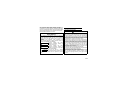
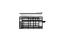
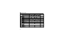
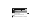
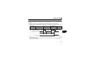
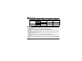
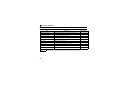
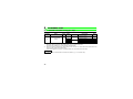
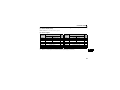
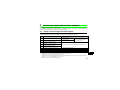
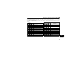
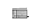
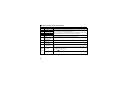
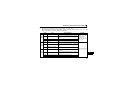
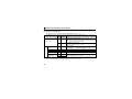
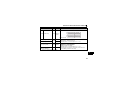
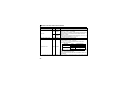
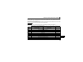
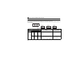
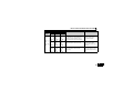
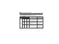
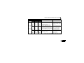
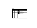
DETAILS OF INPUT AND OUTPUT SIGNALS
Device
No.
RXD
RXE
RXF
RX1A
RX1B
55
Signal
Description
After "1" is set in the frequency setting command/torque command
(RYD) and the frequency setting command/torque command is
Frequency setting completion (RAM) written to the inverter RAM, "1" is set in this signal.
When "0" is set in the frequency setting command/torque
command (RYD), "0" is set in this signal.
After "1" is set in the frequency setting command/torque command
(RYE) and the frequency setting command/torque command is
Frequency setting completion (RAM,
written to the inverter RAM and EEPROM, "1" is set in this signal.
EEPROM)
When "0" is set in the frequency setting command/torque
command (RYE), "0" is set in this signal.
After "1" is set in the instruction code execution request (RYF) and
the processes corresponding to the instruction codes (RWw2, 10,
Instruction code execution completion 12, 14, 16 and 18) are executed, "1" is set in this signal.
When "0" is set in the instruction code execution request (RYF), "0"
is set in this signal.
When an inverter error occurs (protective function is activated), "1"
Error status flag
is set in this signal.
When the inverter goes into the ready status upon completion of
initial setting after power-ON or hardware reset, "1" is set in this
signal. When an inverter error occurs (protective function is
Remote station ready
activated), "0" is set in this signal.
The signal is used as an interlock signal during the write to/read
from the master module.