1
NASA/ESA Conference on Adaptive Hardware and Systems
A New High-Level Reconfigurable Lossless Image Compression System for Space
Applications
Guoxia Yu, Tanya Vladimirova, Xiaofeng Wu, Martin N. Sweeting
Surrey Space Centre,Department of Electronic Engineerin,
University of Surrey, Guildford, GU2 7XH, UK
{g.yu, t.vladimirova, x.wu, m.sweeting}@surrey.ac.uk
architectural exploration. Those most popular tools
include Handel C, Dime C, Impulse C, Synplify DSP and
Xilinx AccelDSP. We use Matlab for the image
compression model, which is then converted to HDL with
Xilinx AccelDSP.
Remote sensing tasks require transmission to ground
of an extensive amount of imaging data with on-board
image compression being the solution to the “Bandwidth
versus Data Volume” dilemma of modern spacecraft [1].
The Consultative Committee for Space Data Systems Lossless
Data
Compression
(CCSDS-LDC)
recommendation [2] is a low complexity algorithm which
also has low memory and power usage. Its error-resilience
functionality is important for the hostile space
environment. To stop error propagation, a sample is
periodically kept uncompressed as a reference. So data
before and after a reference sample are compressed
independently. Therefore error is constrained in a small
region, called Independent Compression Region (ICR).
Being a 2-D type of data, an image can be compressed
further, by using a 2-D prediction scheme, instead of the
default 1-D scheme. However compression of a current
pixel will depend on neighbour pixels of previous lines,
which is contrary to the featured coding independency,
assuming one line of data is fairly larger than one ICR,
which is true for most Earth observation remote sensing
tasks.
In this paper, we introduce a new design, which is a
combination of 2-D prediction and independency coding
by using a scanning scheme beforehand. This new design
could increase the compression ratio by around 93%, with
being only slightly more complex. Its performance is
better than the state-of-the-art JPEG-LS, under the same
conditions.
The image compression core is developed and
integrated into a reconfigurable system-on-chip (SoC) for
payload computing targeting the small satellite platform.
The SoC takes advantage of high-density SRAM-based
FPGAs to accommodate the on-board computer on a
single chip, resulting in an efficient hardware architecture
in terms of power, area and speed.
Abstract
On board image data compression is an important feature
of satellite remote sensing payloads. Reconfigurable
Intellectual Property (IP) cores can enable change of
functionality or modifications. A new and efficient
lossless image compression scheme for space applications
is proposed. In this paper, we present a lossless image
compression IP core designed using AccelDSP, which
gives users high level of flexibility. One typical
configuration is implemented and tested on an FPGA
prototyping board. Finally, it is integrated successfully
into a System-on-Chip platform for payload data
processing and control.
1. Introduction
Recent fast advances in Field Programmable Gate
Arrays (FPGA), such as high clock frequencies and
parallel processing capabilities, have made them a
preferred platform for digital signal processing (DSP).
FPGAs have been widely used in space missions, ranging
from control and data processing tasks in satellites to
Mars rovers.
Reconfigurable hardware like FPGAs crosses the
boundary between software and hardware applying
hardware description languages (HDL) such as VHDL or
Verilog to program and redefine the hardware
architecture. A wide variety of soft Intellectual Property
(IP) cores are distributed in synthesisable HDL format.
However, the alteration of these HDL codes to suit
different application scenarios, is extremely difficult even
to experienced hardware engineers.
Nowadays, high level languages (HLL) like C or
Matlab are used to capture the data processing model. A
class of EDA tools is emerging, which can be employed to
convert automatically from HLL to Register-Transfer
Level (RTL) HDL, or straightaway to FPGA
configuration bit stream. This additional procedure is
developed to speed up the design cycle, and to let
designers concentrate on the algorithmic optimization and
978-0-7695-3166-3/08 $25.00 © 2008 IEEE
DOI 10.1109/AHS.2008.56
183
Authorized licensed use limited to: University of Surrey. Downloaded on December 2, 2009 at 06:29 from IEEE Xplore. Restrictions apply.
lines. Here by adapting BDC to the proposed scan
scheme, we apply an embedded BDC, which means that it
is inserted into the GAP technique. So in order to get a
better prediction, the WN, W, and WS pixel values in
Figure 3, are compensated through the embedded BDC
using the equation below:
In Section 2 and Section 3 the lossless compression
algorithm and the Xilinx AccelDSP software are
introduced accordingly. Then the performance of the
compression algorithm is evaluated in Section 4. Section 5
presents the System Level IP Core Development. In
Section 6, issues related to the configuration and
implementation of the IP core are discussed. Section 7
presents a reconfigurable system-on-chip architecture for
space missions.
E i = E i + ( mean (Oi ) + mean (Oi −1 )) / 2 − mean ( Ei −1 )
Where Ei is the current even column line, accordingly Ei-1
is the previous even column line, Oi and Oi-1 are the two
previous odd column lines. They all consist of 16 pixels,
as defined in the proposed scanning scheme.
2. Lossless Compression Algorithm
In May 1997, the consultative committee for space data
systems (CCSDS) published a recommendation standard
for lossless data compression, which is an extended Rice
algorithm, with added two low-entropy coding options
[3]. In this section the proposed scan scheme plus a 2-D
prediction and the recommendation are presented.
2.1. Proposed
Prediction
Scanning
Scheme
and
(1)
…
…
…
(a) Raster Scan
2-D
…
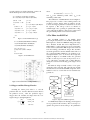
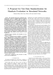
Normally image data are read in raster scan (RS) order
as shown in Figure 1-a. On each line the first pixel is
taken as the reference sample. Hence ICR is just one
horizontal line of data. The scan method, shown in Figure
1-b, named Peanno-Hilbert (PH) scan, is believed to be
the optimum scan to reduce 2-D spatial correlation to 1-D
correlation [4]. To enable a 2-D prediction without
affecting the ICR coding independency, a new vertical
scan (VS) is proposed, which has a “V” shape as shown in
Figure 1-c. This scan goes down vertically, and turns from
the start again after N pixels. N is 16, as it is the number
of samples in the smallest compression unit. Therefore a
2-D prediction can be made using previous vertical
line(s), while inside one ICR.
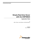
Here the Gradient-Adjusted Predictor (GAP) [5]
method is rotated by 90 degrees in the vertical mode as
shown in Figure 2. The value of the current pixel marked
as a star is predicted by using two pixels above and some
pixels of two previous vertical lines. The definition of the
vertical and horizontal gradients of intensity and the
pseudo-code for the GAP prediction are given in Figure 3.
Linear CCD image sensors used in push-broom
imaging payloads, have different offset and shift registers,
and hence difference in brightness for the even and odd
column pixels. Thus the lesser correlation between odd
and even column pixels will suppress the compression
performance. In [6], a method called Brightness
Difference Compensation (BDC) is reported, which is
able to bring 5.5% further data reduction on JPEG-LS.
BDC is applied to images on a tile-by-tile basis with a tile
size of 512 by 512 pixels. The proposed VS scan needs to
buffer only 16 lines of image data, while BDC needs 512
(b) Peano-Hilbert Scan
.
.
.
.
.
.
.
.
.
.
.
.
.
.
.
.
.
.
.
.
.
.
.
.
…
(c) Proposed Scan
Figure 1. Different scan scheme in the preprocessing part of the compression process
NN
WN
WW
N
W
Reference
WSW
WS
Figure 2a. Vertical GAP
Casual Neighbours
Current
Figure 2b. Reference Band
and current Band
In multispectral images (MS), there exists another
correlation, the spectral correlation. Sometimes the
spatial correlation is much more significant than the
spectral one, while in other cases the spectral
correlation will dominate, which can be established by
comparison of the spectral and spatial gradients. To
take into account both of these correlations, a 3-D
extension to GAP is proposed. The spectral gradient
ds and the switch between normal 2-D GAP and
184
Authorized licensed use limited to: University of Surrey. Downloaded on December 2, 2009 at 06:29 from IEEE Xplore. Restrictions apply.
spectral prediction are defined in Figure 4, where ‘R’
means that the pixel is in the reference band.
where
θ = minimum( xˆi − xmin , xmax − xˆi )
xmin is the minimum possible value, xmax is the
dv = abs(NN-N)+ abs(W-WN)+ abs(W-WS)
and
dh = abs(N-WN)+ abs(W-WW)+ abs(WS-WSW)
maximum possible value.
The architecture of CCSDS-LDC is shown in Figure 5.
The pre-processor consists of the scanning scheme, the
prediction, and the mapper. Then an adaptive encoder
converts the mapped prediction residual into an encoded
bit sequence y. The entropy coder is a collection of
variable-length codes operating in parallel. The coding
option achieving the highest compression is selected, and
the option ID bit pattern is enclosed and forwarded.
if dh-dv > 80
pre = N;
elseif dh-dv < -80
pre = W;
pre = (N + W)/ 2 + (WS-WN)/ 4;
else
if dh-dv > 32
elseif dh-dv > 8
pre = (pre + N)/ 2;
pre = ( 3*pre + N)/ 4;
elseif dh-dv < -32
pre = (pre + W)/ 2;
elseif dh-dv < -8
pre = ( 3*pre + W)/ 4;
end
3. The Xilinx AccelDSP Tool
end
Figure 3. Vertical GAP Prediction [5]
The AccelDSP software is the Matlab signal
processing model synthesis tool from Xilinx, which allows
DSP engineers to transform a Matlab floating-point design
into a hardware module that can be implemented in a
Xilinx FPGA or other technologies. Its most interesting
feature is that a synthesizable RTL design can be achieved
from the floating point M-Code design. The automatic
test-bench generation is another valuable feature. The tool
also could invoke HDL simulation tools, Synthesis tools,
and implementation tools. As shown in the design flow
diagram in Figure 6, AccelDSP verifies the generated
module on each step to be as true as the previous one, or
to be subjectively acceptable with a small difference
during the conversion from floating point design to fixed
point.
The M-Code design normally consists of two parts:
design files and a script file. The script file acts just like
the testbench used in a traditional HDL design flow, but in
addition it serves as a source file for later testbench auto
generations.
ds = abs(WS-RWS-(WSW-RWSW + W-RW)/ 2 )
+ abs(W-RW-(WW-RWW + WN-RWN)/2 )
+ abs(N-RN-(WN-RWN + NN-RNN)/ 2 )
if (ds < dh) & (ds < dv)
pre(kkk) = RC + (W-RW + N-RN)/ 2;
else
Normal 2 D GAP
Figure 4. 3-D GAP Extension
Floating point
(m-file)
Figure 5. The CCSDS-LDC encoding architecture [3]
RTL (VHLD
or Verilog)
Verify
Simulationn
2.2. Mapper and Rice Entropy Encoder
Fixed-point
(m-file or c++)
Assuming the current pixel value is xi , and the
Synthesis
predicted value is x̂i , then the difference between them is
Verify
the prediction error ∆ i . After the prediction stage a
Implementation
mapper takes the residuals and maps them into nonnegative integers, through Equation 4.
0 ≤ ∆i ≤ θ
2∆ i
(4)
δ i = 2 ∆ i − 1 - θ ≤ ∆ i ≤ 0
θ + ∆
otherwise
i
Figure 6. Typical AccelDSP Design Flow
AccelDSP firstly analyzes the floating-point design and
sets up a golden model in memory. The second step is to
quantize the golden model according to the quantization
185
Authorized licensed use limited to: University of Surrey. Downloaded on December 2, 2009 at 06:29 from IEEE Xplore. Restrictions apply.
rules applied by the designer. If no rules are available then
it works automatically based on intrinsic properties. Next
a fix-point design is achieved. Then the same script file is
used to verify the fixed point design, by comparing it with
the saved output results of the golden model, to make sure
that the fixed-point design works correctly. The fourth
step is to generate an RTL design and a testbench at the
same time. ModelSim or other simulation tools are used to
simulate the generated RTL design, which compares the
testbench output with the saved fixed-point simulation
output. If they are exactly the same then it is a “PASS”.
This design flow genuinely speeds up the conversion
process from a Matlab model to a RTL hardware
representation. What’s more, the flow can work
automatically once design rules have been set.
EmbeddedBDC, RS, VS, GAP and CCSDS-LDC are
tested. Table 2 shows that the results in column 6 are
comparable to the results in column 2, which are much
better than JPEG-LS (column 1). By comparing the results
in columns 6 and 7 it can be seen that embedded BDC
only slightly underperforms BDC, however it reduces the
buffer memory size 32 times. Table 2 also shows that the
results of the proposed solution (column 7) are much
better than the results achieved by RS and CCSDS-LS
(column 3), nearly doubling the compression ratio only
with an extra memory buffer of 16 lines image data and a
combination of simple scan scheme and GAP prediction.
It can be concluded that the proposed approach is the
most efficient scheme for lossless data compression with
constrained error propagation functionality.
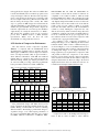
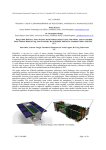
For evaluation of the compression performance of
multispectral images, we use a MS image from the NASA
Landsat7 satellite, which consists of different land types
as shown in Figure 7. 6 out of 8 available bands are used,
as they are sharing the same resolution of 30 m. The bands
of multispectral images are not aligned accurately. So
image registration [7] is required before compression with
3-D prediction. Before the compression of the current
band, the previous band is already compressed and taken
as the reference band, while the first band is compressed
using the intra-band mode. Then according to the derived
displacement between these two bands, the reference one
is translated and resampled with a bilinear model.
4. Evaluation of Compression Performance
The state-of-the-art lossless compression algorithm,
JPEG-LS, is compared with the CCSDS-LDC based
algorithms. Here one ICR consists of 128 times 16 pixels,
which applies to JPEG-LS as well. Compression results in
terms of Compression Ratio (CR) are given in Table 1,
where different combinations of RS, PH, VS, GAP and
CCSDS_LDC are compared. The results show that the
different scanning scheme give similar performance, but
an extra 2-D GAP processing could bring significantly
better performance, which exceeds that of JPEG-LS
Table 1. Compression Ratio on Standard Test Images
CR
JPEGLS
RS+CCS
DS-LDC
PH+CCS
DS-LDC
VS+CCS
DS_LDC
VS+GAP+
CCSDSLDC
Goldhill
Lena
Mandrill
Peppers
AVE
1.57
1.74
1.17
1.62
1.53
1.53
1.6
1.26
1.56
1.49
1.52
1.67
1.24
1.6
1.51
1.5
1.71
1.21
1.59
1.5
1.64
1.77
1.3
1.67
1.6
Table 2. Compression Ratio on Satellite Test Images
CR
D001
D002
D003
D004
D005
AVE
JPEGLS
1
3.48
4.49
2.84
3.47
2.71
3.4
BDC+J
PEGLS
2
3.64
5.32
2.94
3.68
2.78
3.67
RS+CC
SDSLDC
3
1.93
1.73
1.87
1.88
1.83
1.85
BDC+R
S+CCS
DSLDC
BDC+
VS+CC
SDS_L
DC
BDC+
VS+GA
P+CCS
DSLDC
4
3.2
4.69
2.6
3.2
2.39
3.21
5
3.13
4.87
2.52
3.29
2.29
3.22
6
3.68
5.07
2.98
3.63
2.73
3.62
VS+Embe
ddedBDC
GAP+CC
SDS-LDC
7
3.63
4.94
2.96
3.61
2.74
3.58
Figure 7. The Multispectral Test Image (Copyright NASA)
Table 3. Compression Ratio of the Multispectral Test Image
CR
B1
B2
B3
B4
B5
B7
AVE
Five panchromatic images (4m GSD, 6144 by 6144
pixels) captured from the Surrey Satellite Technology Ltd.
(SSTL) ‘Beijing-1’ small satellite are selected, containing
different features. The Beijing-1 panchromatic imager is
of push-broom type, so we could compare performance of
the proposed embedded BDC with that of its complex
rival BDC. Different combinations of JPEG-LS, BDC,
JPEG-LS
(ICR=16x1
28)
RS+CCS
DS-LDC
RS+Ban
dDiff+C
CSDSLDC
VS+2D_
GAP+C
CSDSLDC
VS+Ban
dDiff_2D
_GAP+C
CSDSLDC
VS+3D_
GAP+C
CSDSLDC
1
2.04
2.07
1.90
2.23
1.94
1.84
2.002
2
2.25
2.41
2.17
2.74
2.42
2.19
2.362
3
2.25
2.39
2.34
2.38
2.42
2.36
2.355
4
2.39
2.55
2.32
2.70
2.59
2.31
2.477
5
2.39
2.47
2.43
2.49
2.54
2.46
2.461
6
2.39
2.68
2.46
3.02
2.65
2.46
2.609
Compression results on the multispectral test image in
terms of CR are shown in Table 3, where different
186
Authorized licensed use limited to: University of Surrey. Downloaded on December 2, 2009 at 06:29 from IEEE Xplore. Restrictions apply.
combinations of methods are compared. The results in the
first two columns and the fourth one are derived band by
band, without any interband coding technique. They are
included here for comparison purposes. The results in the
third and fifth column are based on the difference of the
current band with the reference one, which is referred to
as “BandDiff” [8]. The results in the last column derived
with the proposed 3D_GAP technique, give the best
performance out of all.
Firstly, a script file is needed, which provides the input
(or test data) and displays the output for validation
purpose. Test data should be comprehensive. A control
unit module is developed with four control signals
indicating whether the current data is at the point of
“reference sample”, “start segment”, “reference sample
block”, or “block end”. A pre-processing module is then
developed, which is validated by comparing the output
“y” with the expected ones.
The coder part, which takes output of the preprocessing module, is then designed. A block of data,
(block size J), is stored in a FIFO. Each block is coded
separately, by using several coding options. The variablelength code and its length are generated according to the
coding option. Here, the code is separated into two types normal code and zero code. To validate the encoding part,
a comprehensive test data is encoded, and then applied to
a developed de-compression m-function, and it is checked
whether the reconstructed data is exactly the same as the
original one. Also, the obtained compression ratio for the
standard LENA image is confirmed by those in the
literature [9, 10]. The byte formatter converts the variablelength code into byte output, with output enable signal.
The reconfigurable parameters of the IP core include:
the number of bits per pixel, N, the block size, J, the
number of blocks of each reference sample interval, R,
and the number of blocks of each segment, S [3]. As R
depends on the actual application very much, it can also
be configured after the implementation, with the dedicated
‘load’ and ‘RefIntevalValue’ interfaces. These parameters
are adjusted according to different imaging scenarios and
custom requirements.
5. System Level IP Core Development
The IP core is developed based on a clear algorithmic
data flow, taking into account how it will be translated
into HDL, and how it will work on the FPGA. After the
floating-point simulation is finished in Matlab, AccelDSP
is used to analyze the design, and translate it to a fixedpoint design with manual setup of some registers’
quantization for the purpose of area optimization.
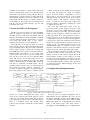
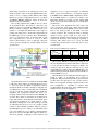
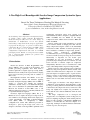
The architecture of the IP core design is shown in
Figure 8. Image data are scanned from the buffer in the
proposed scanning method. The scan module is basically a
memory address generator, which reads the image data
from RAM based on the sequence of generated addresses.
Embedded BDC and GAP are in one module. GAP
requires pixels’ value from two previous vertical lines.
And only those in the first one need embedded BDC,
which will smooth out this GAP related region. For
multispectral images in Band Interleaved by Line (BIL)
format or Band interleaved by Pixel (BIP) format the
extra effort to implement 3-D GAP requires only the
spectral prediction, and the control of selection between
the spectral and spatial prediction. Afterwards, the
prediction residuals are mapped to non-negative integers.
The coding length of each option is computed and the
6. Configuration and Implementation
Figure 8. Lossless image compression IP core design architecture
shortest one is found. Subsequently the entropy coder
sends out the compressed bit stream using the chosen
coding option along with the option ID. The compressed
code is given at the output in bytes with enable signals.
There is a dedicated control logic module, which
generates control signals to each block to ensure seamless
operation.
We have tested one typical configuration and its
implementation. In this configuration, N is 8; J is 16; S is
64; and the default R is 32. The converted RTL design is
synthesized and implemented in three different Xilinx
FPGA chips. Their costs of implementation are listed in
Table 4. The Virtex4 chips could easily achieve a
throughput more than 800 Mbps. Its cost implementation,
187
Authorized licensed use limited to: University of Surrey. Downloaded on December 2, 2009 at 06:29 from IEEE Xplore. Restrictions apply.
is reasonable, by comparison with the JPEG-LS FPGA
implementation in [11], which uses around 11,272 LUTs
and 13 BRAM, with 64 MHz of Frequency, on a
Spartan3E 3S1200E-5.
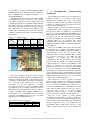
The implementation was tested on the ZestSC2 FPGA
prototyping board shown in Figure 9 [12]. In this
prototyping system, the personal computer (PC) host
communicates with the on-board FPGA and thereafter the
data memory through a USB interface. First the host
writes image data to the data memory, and then it triggers
the compression core running on the FPGA to start
reading data, compressing data, and at the same time
sending the compressed data back to the Host through the
USB interface.
7.
A
Reconfigurable
Architecture
The resultant image compression core is integrated as a
peripheral module in a System-on-a-Chip design,
implemented on an FPGA chip as part of the payload
controller of a small satellite. In addition to the image
compression, other IP cores for space applications are in a
process of development [14, 15].
The SoC design is targeted at the Xilinx Virtex series
of FPGAs. The central processing unit is the LEON3
microprocessor, which is a SPARC V8 soft intellectual
property core written in VHDL [16]. The SPARC V8 is a
RISC architecture with typical features like large number
of registers and few and simple instruction formats.
However, the LEON3 IP core is more than a SPARC
compatible CPU. It is also equipped with various
peripherals that interconnect through two types of the
AMBA bus (AHB and APB), e.g. Ethernet, SpaceWire,
PCI, UART etc.
The SoC is an AMBA centric design and subsystems
of the OBC can be added to the LEON3 processor
providing that they are AMBA interfaced. The AHB is a
high-performance system bus and provides highbandwidth operations. On the other hand, APB is a simple
and low-power extension to the AHB bus. The
compression core requires fast and intensive
communication with the data memory, and not much
interaction with the LEON3 core. Hence the image
compression IP core is connected to the APB bus, for the
purpose of achieving low-power and high system
performance. The IP core is controlled by the LEON3
processor for switching on/off. A direct AHB-like highspeed image bus is designed in order that the compression
core can send/receive data to/from the memory bypass the
LEON3 CPU. This extra image bus will make the primary
AHB bus and modules on it free to use, even when the
compression is working in full-speed.
The compression core uses a separate clock input.
Hence it can be configured at a much higher frequency
than the LEON3 CPU speed. For example the LEON3
processor is clocked at 70 MHz, but the compression core
is clocked at 100 MHz in the SoC implementation on the
Avnet Virtex-4 LX60 evaluation board [17]. It has a
power-save mode if there is no need of image
compression. When an image is coming, the LEON3
processor will send a command to activate the IP core.
The SoC is also capable of partial run-time
reconfiguration, which enables us to improve the IP cores
even after the spacecraft is launched. Starting from the
Virtex II series, Xilinx Virtex FPGAs have integrated an
internal configuration access port (ICAP) into the
programmable fabric, which enables the user to write
software programs that modify the circuit structure and
Table 4. Costs of Implementation
Resources
FPGA
LUTs &
percentage
use
SP3-2000-4c
XC4VSX35-12c
XC4VLX60-10c
6136 14%
5711 18%
5903 11%
Register
bits
&
percentage
use
1965 4%
1757 5%
1720 4%
Multipliers
9 Block Mult
8/192 DSP48
8/64 DSP48
Estimated
Frequency
(150Mhz
Requested)
74.7Mhz
150.3Mhz
125.2Mhz
Figure 9. The configuration implementation prototyping system
[12]
The power consumption measured on the prototyping
system confirms the results estimated with Xilinx Xpower,
which are both shown in Table 5. The Dynamic power
consumption on the ZestSC2 prototyping board is higher,
as it is the sum of the dynamic power of all active
components, not just the compression core. This
prototyping board provides a clock of 48 MHz, at which
the compression core is working, which means it has 48
Mpixels/second of throughput. So the energy required to
compress a 95 MByte image (10000 by 10000 pixels) is
around 0.072 J. Its 14 mW/Mpixels/second is a little
lower than 15 mW/Mpixels/second of the 3.3 V ASIC
implementation of CCSDS-LDC in [13].
Table 5. Power Consumption Comparison
Xpower Estimation
ZestSC2 Board Meaurements
Dynamic
35.96 mW
60 mW
System-on-Chip
Quiescent
624.6 mW
625 mW
188
Authorized licensed use limited to: University of Surrey. Downloaded on December 2, 2009 at 06:29 from IEEE Xplore. Restrictions apply.
functionality at run-time for an embedded processor. The
ICAP is actually a subset of the SelectMAP interface [18],
which is used to configure Xilinx FPGAs. The Xilinx
FPGAs also provide on-chip hard-wired cores, e.g. Block
SelectRAM (BRAM), multipliers. Figure 10 shows the
diagram of the SoC architecture.
The on-chip peripheral bus (OPB) is used to connect
all the ICAP modules. The ICAP is connected to the
LEON3 processor via the OPB-to-AHB bridge. Once the
FPGA is initially configured, the ICAP is used as an
interface to reconfigure the FPGA. The control logic for
reading and writing data to the ICAP is implemented in
the LEON3 processor as a software driver. The BRAM is
used as a configuration cache. As the bitstream of each
SoC component can be stored on board in a Flash
memory, the bitstream of a new or upgraded component
can be uploaded through the satellite uplink from the
ground station.
application code for rapid development of embedded
Linux systems. The LEON port of SnapGear supports
both MMU and non-MMU LEON configurations. In fact,
the non-MMU kernel is a uClinux port similar to the
Microblaze uClinux port. In this case the original ICAP
driver can be used in the LEON3 processor with minor
modifications.
The device driver implements the read(), write() and
ioctl() system calls: read() reads a frame from the ICAP
into a user memory buffer (BRAM); write() writes a frame
from a user memory buffer to the ICAP; and ioctl()
controls operations, like querying the status or changing
operation modes. Upon system boot, the driver is
automatically installed in the SnapGear, and the ICAP is
registered in the Linux device subsystem, appearing as
/dev/icap. This feature allows us to access the ICAP
module using standard Linux system calls, such as open,
read and write.
Table 6. Virtex-4 LX60 Resource Utilisation
Resources
SoC
With compression
Without compression
Difference
LUTs
&
percentage
use
20267 38%
14387 27%
5880 11%
Register bits
& percentage
use
8724
6794
1930
16%
12%
4%
DSP48
11/64
2/64
9/64
Block
RAM
31/160
29/160
2/160
The resource utilisation of the Virtex-4 LX60 chip for
the SoC implementation with and without the compression
core are presented in Table 6. Compared to Table 4, the
synthesis results show that the compression core needs
around 200 more registers and 2 more BRAM, due to the
additional image bus and the interface between the IP core
and the LEON3 processor.
This LEON-based SoC architecture with the support of
ICAP is capable of reconfiguring and evolving its
peripherals. The partial bitstream can be generated at the
ground station and uploaded to the on-board memory.
Hence we can upgrade our image compression IP core if a
new configuration or algorithm is required. This
reconfigurability has been tested on the AVNET Virtex-4
LX60 board [17] as shown in Figure 11.
Figure 10. The SoC architecture of the on-board controller
(OBC)
The ICAP device driver is available in the Xilinx EDK
toolkit. The driver enables an embedded microprocessor
to read and write the FPGA configuration memory
through the ICAP at run-time. On-chip reconfiguration is
accomplished by using a read-modify-write mechanism
[19]. To modify the on-chip subsystems, the ICAP first
determines the configuration frames that need to be
modified, and then reads each frame into the BRAM once
at a time. The contents of each frame are modified before
being written back to the ICAP. The current ICAP driver
only supports modification of a single frame at a time.
The driver is managed by a real-time operating system in
an embedded microprocessor core. For example, Xilinx
released a driver running in uClinux, which is ported to
the MicroBlaze processor. There is an embedded Linux
port to the LEON3 processor, which is called SnapGear
that can be used for the OBC. The SnapGear Linux is a
full source package, comprising a kernel, libraries and
Figure 11. The SoC implementation demo system [17]
189
Authorized licensed use limited to: University of Surrey. Downloaded on December 2, 2009 at 06:29 from IEEE Xplore. Restrictions apply.
8. Conclusions
[7]
A new efficient lossless image compression scheme is
proposed, which is suitable for real satellite remote
sensing images. It consists of a new scanning scheme, a
modified 2-D prediction method, and a novel 3-D
extension prediction method for multispectral images. A
new reconfigurable compression IP core is implemented
in VHDL from a high-level Matlab code, which can easily
be modified at the algorithmic level. A typical
configuration and its implementation are successfully
tested on an FPGA prototyping system.
The compression core is integrated successfully into a
SoC platform for payload processing and control. It is
attached as a peripheral to LEON3 processor via the
AHB/APB bus to achieve low-power and higher system
performance. A dedicated image bus provides to the core
high-speed access to the data memory allowing the
LEON3 processor to perform other data processing tasks.
[8]
[9]
[10]
[11]
Acknowledgments
The authors gratefully acknowledge the provision of
satellite images from SSTL and DMC International
Imaging for the experimental results in this paper. This
research is sponsored by the University of Surrey, an ORS
PhD award and EPSRC grant EP/C546318/01.
[12]
[13]
References
[1]
[2]
[3]
[4]
[5]
[6]
[14]
T. Vladimirova, M. Meerman, and A. Curiel, "OnBoard Compression of Multispectral Images for
Small Satellites," in Geoscience and Remote
Sensing Symposium, 2006. IGARSS 2006. IEEE
International Conference on, 2006, pp. 3533-3536.
P.-S. Yeh, G. A. Moury, and P. Armbruster,
"CCSDS Data Compression Recommendation:
Development and Status," in Applications of
Digital Image Processing XXV, Seattle, WA, USA,
2002, pp. 302-313.
CCSDS,
Lossless
Data
Compression,
Recommendation for space data system standards
vol. 121.0-B-1: CCSDS, 1997.
S. Atek and T. Vladimirova, "A New Lossless
Compression Method for Small Satellite On-Board
Imaging.pdf," WSEAS Transactions Mathematics,
vol. 1, no. 1-4, pp. 171-176, 2002.
X. Wu and N. Memon, "Context-based, adaptive,
lossless image coding," Communications, IEEE
Transactions on, vol. 45, pp. 437-444, 1997.
G. Yu, T. Vladimirova, and M. Sweeting, "A New
Automatic
On-Board
Multispectral
Image
Compression System for Leo Earth Observation
Satellites," in Digital Signal Processing, 2007 15th
[15]
[16]
[17]
[18]
[19]
IEEE International Conference on, 2007, pp. 395398.
G. Yu, T. Vladimirova, and M. Sweeting,
"Autonomous Band Registration for ON-Board
Applications," in 2007 IEEE International
Conference
on
Signal
Processing
and
Communications, Dubai, UAE, 2007, pp. 13271330.
P.-S. Yeh, "Multispectral Prediction: a two-step
predictor," G. Yu, Ed.: Personal Communication,
2007.
M. Gilles, R. André, and L. Guy, "Overview And
General Principles Of Source Coding, Channel
Coding & Modulation In CCSDS And DVB-S
Standards," in 11th European Signal Processing
Conference (EUSIPCO), Toulouse, France, 2002,
pp. 581-584.
L. H. Miles and J. A. Venbrux, "Szip Compression
2.0," University of New Mexico (UNM), 2005, p.
http://hdfgroup.com/doc_resource/SZIP/.
CAST, "JPEG-LS Encoder Core — XILINX FPGA
Implementation
Results,"
2007,
pp.
http://www.cast-inc.com/cores/jpegls-e/jpegls_exilinx.htm.
"FPGA USB BOARDS - ZestSC2," Orange Tree
Technologies,
2007,
p.
http://www.orangetreetech.com/fpga_board_zestsc
2.html.
P.-S. Yeh, "Implementation of CCSDS lossless
data compression for space and data archival
applications," in Proceedings of the Space
Operations Conference, 2002.
T. Vladimirova and M. N. Sweeting, "System-on-aChip Development for Small Satellite On-Board
Data Handling," Journal of Aerospace Computing,
Information, and Communication, AIAA, vol. 01,
pp. 36-43, January 2004.
T. Vladimirova and X. Wu, "On-Board Partial RunTime
Reconfiguration
for
Pico-Satellite
Constellations," in the 1st NASA/ESA Conference
on Adaptive Hardware and Systems (AHS 2006),
2006, pp. 262-269.
J. Gaisler, "GRLIB IP Library User’s Manual
(Version 1.0.4)," Gaisler Research, 2005.
"Xilinx Virtex-4 LX Evaluation Kit ": Avnet
Electronics, 2007, p. http://www.avnet.com/.
B. Blodget, P. James-Roxby, E. Keller, S.
McMillan, and P. Sundararajan, "A Selfreconfiguration Platform," in 13th International
Conference on Field-Programmable Logic and
Applications, Lisbon, Portugal, 2003, pp. 565-574.
Xilinx, "Processor IP Reference Guide," Xilinx
DataSheet, Feb. 2005.
190
Authorized licensed use limited to: University of Surrey. Downloaded on December 2, 2009 at 06:29 from IEEE Xplore. Restrictions apply.