1
Developer’s Guide
Borland®
™
Delphi 7
for Windows
®
Borland Software Corporation
100 Enterprise Way, Scotts Valley, CA 95066-3249
www.borland.com
Refer to the DEPLOY document located in the root directory of your Delphi 7 product for a complete list of files that
you can distribute in accordance with the Delphi 7 License Statement and Limited Warranty.
Borland Software Corporation may have patents and/or pending patent applications covering subject matter in this
document. Please refer to the product CD or the About dialog box for the list of applicable patents. The furnishing of
this document does not give you any license to these patents.
COPYRIGHT © 1983–2002 Borland Software Corporation. All rights reserved. All Borland brand and product names
are trademarks or registered trademarks of Borland Software Corporation in the United States and other countries.
All other marks are the property of their respective owners.
Printed in the U.S.A.
HDE1370WW21001 7E5R0802
0203040506-9 8 7 6 5 4 3 2 1
D3
Contents
Chapter 1
Introduction
Using object variables . . . . . . . . . . .
Creating, instantiating, and destroying
objects . . . . . . . . . . . . . . . . . . .
Components and ownership . . . . . .
Defining new classes . . . . . . . . . . . .
Using interfaces . . . . . . . . . . . . . . .
Using interfaces across the hierarchy .
Using interfaces with procedures . . .
Implementing IInterface . . . . . . . .
TInterfacedObject . . . . . . . . . . . .
Using the as operator with interfaces .
Reusing code and delegation. . . . . .
Using implements for delegation .
Aggregation . . . . . . . . . . . . .
Memory management of interface
objects. . . . . . . . . . . . . . . . . .
Using reference counting . . . . . .
Not using reference counting. . . .
Using interfaces in distributed
applications . . . . . . . . . . . . . .
1-1
What’s in this manual? . . . . . . . . . . . . . . 1-1
Manual conventions . . . . . . . . . . . . . . . . 1-2
Developer support services . . . . . . . . . . . . 1-3
Part I
Programming with Delphi
Chapter 2
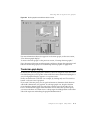
Developing applications with Delphi 2-1
Integrated development environment .
Designing applications . . . . . . . . .
Creating projects . . . . . . . . . . . . .
Editing code . . . . . . . . . . . . . . .
Compiling applications . . . . . . . . .
Debugging applications . . . . . . . . .
Deploying applications . . . . . . . . .
.
.
.
.
.
.
.
.
.
.
.
.
.
.
.
.
.
.
.
.
.
.
.
.
.
.
.
.
.
.
.
.
.
.
.
2-1
2-2
2-3
2-4
2-4
2-5
2-5
Chapter 3
Using the component library
Understanding the component library . .
Properties, methods, and events . . . .
Properties . . . . . . . . . . . . . . .
Methods . . . . . . . . . . . . . . . .
Events . . . . . . . . . . . . . . . . .
User events . . . . . . . . . . . . . .
System events . . . . . . . . . . . . .
Internal events . . . . . . . . . . . .
Objects, components, and controls . . . . .
TObject branch . . . . . . . . . . . . . .
TPersistent branch . . . . . . . . . . . .
TComponent branch . . . . . . . . . . .
TControl branch . . . . . . . . . . . . .
TWinControl/TWidgetControl branch
.
.
.
.
.
.
.
.
.
.
.
.
.
.
. 3-1
. 3-3
. 3-3
. 3-4
. 3-4
. 3-4
. 3-4
. 3-4
. 3-5
. 3-6
. 3-7
. 3-7
. 3-9
. 3-10
What is an object? . . . . . . . . . . . . . . .
Examining a Delphi object . . . . . . . .
Changing the name of a component . . .
Inheriting data and code from an object. . .
Scope and qualifiers . . . . . . . . . . . . . .
Private, protected, public, and published
declarations . . . . . . . . . . . . . . . .
.
.
.
.
.
.
.
.
.
.
.
.
.
.
.
.
.
.
.
.
.
.
.
.
.
.
.
.
.
.
.
.
.
.
. 4-8
. 4-9
. 4-9
4-12
4-13
4-14
4-14
4-15
4-16
4-16
4-17
4-18
. . . 4-18
. . . 4-19
. . . 4-20
. . . 4-21
Using BaseCLX
Using streams . . . . . . . . . . . . . . . . .
Using streams to read or write data . . .
Stream methods for reading and
writing. . . . . . . . . . . . . . . . .
Reading and writing components . .
Reading and writing strings . . . . .
Copying data from one stream to
another . . . . . . . . . . . . . . . . . .
Specifying the stream position and size.
Seeking to a specific position . . . . .
Using Position and Size properties .
Working with files . . . . . . . . . . . . . .
Approaches to file I/O . . . . . . . . . .
Using file streams . . . . . . . . . . . . .
Creating and opening files using
file streams . . . . . . . . . . . . . .
Using the file handle . . . . . . . . .
Manipulating files . . . . . . . . . . . . .
Deleting a file. . . . . . . . . . . . . .
Finding a file . . . . . . . . . . . . . .
Renaming a file. . . . . . . . . . . . .
File date-time routines . . . . . . . .
Copying a file . . . . . . . . . . . . .
Chapter 4
Using the object model
.
.
.
.
.
.
.
.
.
.
.
.
Chapter 5
3-1
.
.
.
.
.
.
.
.
.
.
.
.
.
.
. . . . 4-7
4-1
4-1
4-2
4-4
4-5
4-5
. . 4-6
iii
5-1
. . . 5-2
. . . 5-2
. . . 5-2
. . . 5-3
. . . 5-3
.
.
.
.
.
.
.
.
.
.
.
.
.
.
. 5-4
. 5-4
. 5-4
. 5-5
. 5-5
. 5-6
. 5-6
.
.
.
.
.
.
.
.
.
.
.
.
.
.
.
.
. 5-7
. 5-8
. 5-8
. 5-8
. 5-8
5-10
5-10
5-11
Working with ini files and the system
Registry . . . . . . . . . . . . . . . . . . .
Using TIniFile and TMemIniFile . .
Using TRegistryIniFile . . . . . . . .
Using TRegistry . . . . . . . . . . . .
Working with lists . . . . . . . . . . . . . .
Common list operations . . . . . . . . .
Adding list items . . . . . . . . . . .
Deleting list items. . . . . . . . . . .
Accessing list items . . . . . . . . . .
Rearranging list items . . . . . . . .
Persistent lists. . . . . . . . . . . . . . .
Working with string lists . . . . . . . . . .
Loading and saving string lists . . . . .
Creating a new string list . . . . . . . .
Short-term string lists . . . . . . . .
Long-term string lists. . . . . . . . .
Manipulating strings in a list . . . . . .
Counting the strings in a list. . . . .
Accessing a particular string . . . .
Locating items in a string list . . . .
Iterating through strings in a list . .
Adding a string to a list . . . . . . .
Moving a string within a list. . . . .
Deleting a string from a list . . . . .
Associating objects with a string list
Working with strings . . . . . . . . . . . .
Wide character routines . . . . . . . . .
Commonly used long string routines .
Commonly used routines for
null-terminated strings. . . . . . . . .
Declaring and initializing strings . . . .
Mixing and converting string types . .
String to PChar conversions. . . . . . .
String dependencies . . . . . . . . .
Returning a PChar local variable . .
Passing a local variable as a PChar .
Compiler directives for strings . . . . .
Creating drawing spaces . . . . . . . . . .
Printing . . . . . . . . . . . . . . . . . . . .
Converting measurements . . . . . . . . .
Performing conversions . . . . . . . . .
Performing simple conversions . . .
Performing complex conversions . .
Adding new measurement types . . . .
Creating a simple conversion family
and adding units . . . . . . . . . . . .
Declare variables . . . . . . . . . . .
Register the conversion family . . .
.
.
.
.
.
.
.
.
.
.
.
.
.
.
.
.
.
.
.
.
.
.
.
.
.
.
.
.
.
.
.
.
.
.
.
.
.
.
.
.
.
.
.
.
.
.
.
.
.
.
.
.
.
.
.
.
. 5-11
. 5-12
. 5-13
. 5-13
. 5-14
. 5-15
. 5-15
. 5-15
. 5-16
. 5-16
. 5-16
. 5-17
. 5-17
. 5-18
. 5-18
. 5-18
. 5-20
. 5-20
. 5-20
. 5-20
. 5-20
. 5-21
. 5-21
. 5-21
. 5-22
. 5-22
. 5-22
. 5-23
.
.
.
.
.
.
.
.
.
.
.
.
.
.
.
.
.
.
.
.
.
.
.
.
.
.
.
.
.
.
. 5-26
. 5-27
. 5-28
. 5-28
. 5-29
. 5-29
. 5-29
. 5-30
. 5-31
. 5-32
. 5-33
. 5-33
. 5-33
. 5-33
. 5-34
Register measurement units . . . . .
Use the new units . . . . . . . . . . .
Using a conversion function . . . . . . .
Declare variables . . . . . . . . . . . .
Register the conversion family . . . .
Register the base unit . . . . . . . . .
Write methods to convert to and
from the base unit . . . . . . . . . .
Register the other units . . . . . . . .
Use the new units . . . . . . . . . . .
Using a class to manage conversions . .
Creating the conversion class. . . . .
Declare variables . . . . . . . . . . . .
Register the conversion family and
the other units . . . . . . . . . . . .
Use the new units . . . . . . . . . . .
Defining custom variants . . . . . . . . . .
Storing a custom variant type’s data . .
Creating a class to enable the custom
variant type. . . . . . . . . . . . . . . .
Enabling casting . . . . . . . . . . . .
Implementing binary operations. . .
Implementing comparison
operations. . . . . . . . . . . . . . .
Implementing unary operations . . .
Copying and clearing custom variants .
Loading and saving custom
variant values. . . . . . . . . . . . .
Using the TCustomVariantType
descendant . . . . . . . . . . . . . .
Writing utilities to work with a custom
variant type. . . . . . . . . . . . . . . .
Supporting properties and methods
in custom variants . . . . . . . . . . . .
Using TInvokeableVariantType . . .
Using TPublishableVariantType . . .
.
.
.
.
.
.
.
.
.
.
.
.
5-35
5-35
5-36
5-36
5-36
5-36
.
.
.
.
.
.
.
.
.
.
.
.
5-36
5-37
5-37
5-37
5-38
5-39
.
.
.
.
.
.
.
.
5-39
5-40
5-40
5-41
. . 5-42
. . 5-42
. . 5-44
. . 5-46
. . 5-47
. . 5-48
. . 5-49
. . 5-50
. . 5-50
. . 5-51
. . 5-51
. . 5-53
Chapter 6
Working with components
Setting component properties . . . . . . . .
Setting properties at design time . . . .
Using property editors . . . . . . . .
Setting properties at runtime. . . . . . .
Calling methods. . . . . . . . . . . . . . . .
Working with events and event handlers .
Generating a new event handler. . . . .
Generating a handler for a component’s
default event . . . . . . . . . . . . . . .
Locating event handlers . . . . . . . . .
. . . 5-34
. . . 5-35
. . . 5-35
iv
6-1
.
.
.
.
.
.
.
.
.
.
.
.
.
.
. 6-2
. 6-2
. 6-3
. 6-3
. 6-3
. 6-3
. 6-4
. . . 6-4
. . . 6-4
Associating an event with an existing event
handler. . . . . . . . . . . . . . . . . . . . .
Using the Sender parameter . . . . . . . .
Displaying and coding shared events . .
Associating menu events with event
handlers . . . . . . . . . . . . . . . . . . . .
Deleting event handlers . . . . . . . . . . . .
Cross-platform and non-cross-platform
components . . . . . . . . . . . . . . . . . . . .
Adding custom components to the
Component palette . . . . . . . . . . . . . .
Adding graphical objects to a string list
Adding images to an application . .
Adding images to a string list . . . .
Drawing owner-drawn items. . . . .
Sizing owner-draw items . . . . . . . . .
Drawing owner-draw items . . . . . . .
6-5
6-5
6-5
6-6
6-6
Implementing drag and drop in controls . .
Starting a drag operation . . . . . . . . .
Accepting dragged items . . . . . . . . .
Dropping items . . . . . . . . . . . . . . .
Ending a drag operation. . . . . . . . . .
Customizing drag and drop with
a drag object. . . . . . . . . . . . . . . .
Changing the drag mouse pointer . . . .
Implementing drag and dock in controls . .
Making a windowed control a
docking site . . . . . . . . . . . . . . . .
Making a control a dockable child . . . .
Controlling how child controls
are docked . . . . . . . . . . . . . . . . .
Controlling how child controls
are undocked . . . . . . . . . . . . . . .
Controlling how child controls respond
to drag-and-dock operations . . . . . .
Working with text in controls. . . . . . . . .
Setting text alignment . . . . . . . . . . .
Adding scroll bars at runtime . . . . . . .
Adding the clipboard object. . . . . . . .
Selecting text . . . . . . . . . . . . . . . .
Selecting all text . . . . . . . . . . . . . .
Cutting, copying, and pasting text . . . .
Deleting selected text . . . . . . . . . . .
Disabling menu items . . . . . . . . . . .
Providing a pop-up menu . . . . . . . . .
Handling the OnPopup event. . . . . . .
Adding graphics to controls . . . . . . . . .
Indicating that a control is
owner-drawn . . . . . . . . . . . . . . .
.
.
.
.
.
6-9
Creating applications . . . . . . . . . . . .
GUI applications. . . . . . . . . . . . .
User interface models . . . . . . . .
SDI applications . . . . . . . . . . .
MDI applications. . . . . . . . . . .
Setting IDE, project, and compiler
options . . . . . . . . . . . . . . .
Programming templates . . . . . . . .
Console applications . . . . . . . . . .
Service applications . . . . . . . . . . .
Service threads . . . . . . . . . . . .
Service name properties. . . . . . .
Debugging service applications . .
Creating packages and DLLs . . . . . . .
When to use packages and DLLs . . .
Writing database applications . . . . . . .
Distributing database applications . .
Creating Web server applications . . . . .
Creating Web Broker applications . . .
Creating WebSnap applications . . . .
Creating Web Services applications . .
Writing applications using COM . . . . .
Using COM and DCOM . . . . . . . .
Using MTS and COM+ . . . . . . . . .
Using data modules . . . . . . . . . . . .
Creating and editing standard
data modules. . . . . . . . . . . . . .
Naming a data module and its
unit file . . . . . . . . . . . . . . .
Placing and naming components .
Using component properties and
events in a data module . . . . . .
Creating business rules in a data
module . . . . . . . . . . . . . . .
Accessing a data module from a form
Adding a remote data module to an
application server project . . . . . . .
7-1
7-1
7-2
7-3
7-3
. . 7-3
. . 7-4
. . 7-4
. . 7-4
. . 7-5
. . 7-5
. . 7-6
.
.
.
.
.
.
.
.
.
.
.
.
.
7-14
7-14
7-14
7-15
7-16
7-17
Building applications, components, and
libraries
8-1
7-1
.
.
.
.
.
.
.
.
.
.
.
Chapter 8
6-7
Chapter 7
Working with controls
.
.
.
.
.
.
. 7-6
. 7-6
. 7-7
. 7-7
. 7-8
. 7-9
. 7-9
. 7-10
. 7-10
. 7-11
. 7-11
. 7-12
. 7-13
. . 7-13
v
.
.
.
.
.
.
.
.
.
.
.
.
.
.
.
. 8-1
. 8-2
. 8-2
. 8-2
. 8-2
.
.
.
.
.
.
.
.
.
.
.
.
.
.
.
.
.
.
.
.
.
.
.
.
.
.
.
.
.
.
.
.
.
.
.
.
.
.
.
.
.
.
.
.
.
.
.
.
.
.
.
.
.
.
.
.
.
. 8-3
. 8-3
. 8-4
. 8-5
. 8-7
. 8-9
. 8-9
8-10
8-11
8-11
8-12
8-12
8-13
8-14
8-14
8-15
8-15
8-15
8-16
. . . 8-16
. . . 8-17
. . . 8-18
. . . 8-18
. . . 8-19
. . . 8-19
. . . 8-20
Using the Object Repository . . . . . . . . .
Sharing items within a project . . . . . .
Adding items to the Object Repository .
Sharing objects in a team environment .
Using an Object Repository item
in a project . . . . . . . . . . . . . . . . .
Copying an item . . . . . . . . . . . .
Inheriting an item. . . . . . . . . . . .
Using an item . . . . . . . . . . . . . .
Using project templates . . . . . . . . . .
Modifying shared items . . . . . . . . . .
Specifying a default project, new form,
and main form . . . . . . . . . . . . . .
Enabling Help in applications . . . . . . . .
Help system interfaces . . . . . . . . . . .
Implementing ICustomHelpViewer . . .
Communicating with the Help
Manager . . . . . . . . . . . . . . . . . .
Asking the Help Manager for
information . . . . . . . . . . . . . . . .
Displaying keyword-based Help . . . . .
Displaying tables of contents . . . . . . .
Implementing IExtendedHelpViewer . .
Implementing IHelpSelector . . . . . . .
Registering Help system objects . . . . .
Registering Help viewers . . . . . . .
Registering Help selectors . . . . . . .
Using Help in a VCL application. . . . . . .
How TApplication processes VCL Help .
How VCL controls process Help . . . . .
Using Help in a CLX application. . . . . . .
How TApplication processes CLX Help .
How CLX controls process Help . . . . .
Calling a Help system directly . . . . . . . .
Using IHelpSystem . . . . . . . . . . . . . .
Customizing the IDE Help system . . . . . .
.
.
.
.
. 8-20
. 8-20
. 8-21
. 8-21
.
.
.
.
.
.
. 8-21
. 8-21
. 8-22
. 8-22
. 8-22
. 8-22
.
.
.
.
. 8-23
. 8-23
. 8-24
. 8-24
Adding forms . . . . . . . . . . . . . . . .
Linking forms . . . . . . . . . . . . . .
Avoiding circular unit references . . .
Managing layout . . . . . . . . . . . . . .
Using forms . . . . . . . . . . . . . . . . . . .
Controlling when forms reside
in memory . . . . . . . . . . . . . . . . .
Displaying an auto-created form. . . .
Creating forms dynamically . . . . . .
Creating modeless forms such
as windows . . . . . . . . . . . . . . .
Creating a form instance using a local
variable . . . . . . . . . . . . . . . . .
Passing additional arguments to forms . .
Retrieving data from forms. . . . . . . . .
Retrieving data from modeless forms .
Retrieving data from modal forms. . .
Reusing components and groups of
components . . . . . . . . . . . . . . . . . .
Creating and using component templates . .
Working with frames . . . . . . . . . . . . . .
Creating frames . . . . . . . . . . . . . . .
Adding frames to the Component
palette . . . . . . . . . . . . . . . . . . . .
Using and modifying frames. . . . . . . .
Sharing frames. . . . . . . . . . . . . . . .
Developing dialog boxes . . . . . . . . . . . .
Using open dialog boxes . . . . . . . . . .
Organizing actions for toolbars and
menus . . . . . . . . . . . . . . . . . . . . .
What is an action? . . . . . . . . . . . . . .
Setting up action bands . . . . . . . . . . .
Creating toolbars and menus . . . . . . .
Adding color, patterns, or pictures
to menus, buttons, and toolbars . . .
Adding icons to menus and
toolbars . . . . . . . . . . . . . . . . .
Selecting menu and toolbar styles . . .
Creating dynamic menus . . . . . . . .
Creating toolbars and menus that
users can customize . . . . . . . . . .
Hiding unused items and categories
in action bands . . . . . . . . . . . . .
Creating most recently used
(MRU) lists . . . . . . . . . . . . . . .
. . 8-25
.
.
.
.
.
.
.
.
.
.
.
.
.
.
.
.
.
. 8-25
. 8-26
. 8-27
. 8-27
. 8-28
. 8-29
. 8-29
. 8-29
. 8-30
. 8-30
. 8-30
. 8-31
. 8-31
. 8-31
. 8-32
. 8-32
. 8-33
Chapter 9
Developing the application user
interface
Controlling application behavior. .
Working at the application level
Handling the screen . . . . . . .
Setting up forms . . . . . . . . . . .
Using the main form . . . . . . .
Hiding the main form . . . . . .
.
.
.
.
.
.
.
.
.
.
.
.
.
.
.
.
.
.
9-1
.
.
.
.
.
.
.
.
.
.
.
.
.
.
.
.
.
.
.
.
.
.
.
.
9-1
9-2
9-2
9-3
9-3
9-3
vi
.
.
.
.
.
. 9-4
. 9-4
. 9-4
. 9-5
. 9-6
. . 9-6
. . 9-6
. . 9-7
. . 9-8
.
.
.
.
.
. 9-8
. 9-8
. 9-9
. 9-9
9-11
.
.
.
.
9-13
9-13
9-14
9-14
.
.
.
.
.
9-15
9-15
9-16
9-17
9-17
.
.
.
.
9-18
9-19
9-20
9-20
. 9-22
. 9-22
. 9-23
. 9-24
. 9-24
. 9-24
. 9-25
Using action lists . . . . . . . . . . . . . . .
Setting up action lists . . . . . . . . . .
What happens when an action fires . .
Responding with events . . . . . . .
How actions find their targets . . . .
Updating actions . . . . . . . . . . . . .
Predefined action classes . . . . . . . .
Writing action components . . . . . . .
Registering actions . . . . . . . . . . . .
Creating and managing menus. . . . . . .
Opening the Menu Designer . . . . . .
Building menus . . . . . . . . . . . . . .
Naming menus . . . . . . . . . . . .
Naming the menu items . . . . . . .
Adding, inserting, and deleting
menu items . . . . . . . . . . . . .
Adding separator bars . . . . . . . .
Specifying accelerator keys and
keyboard shortcuts . . . . . . . . .
Creating submenus. . . . . . . . . . . .
Creating submenus by demoting
existing menus . . . . . . . . . . .
Moving menu items . . . . . . . . .
Adding images to menu items . . .
Viewing the menu . . . . . . . . . .
Editing menu items in the Object
Inspector . . . . . . . . . . . . . . . . .
Using the Menu Designer context
menu . . . . . . . . . . . . . . . . . . .
Commands on the context menu . .
Switching between menus at
design time . . . . . . . . . . . . .
Using menu templates . . . . . . . . . .
Saving a menu as a template . . . . . .
Naming conventions for template
menu items and event handlers . .
Manipulating menu items at runtime .
Merging menus . . . . . . . . . . . . . .
Specifying the active menu: Menu
property . . . . . . . . . . . . . . .
Determining the order of merged
menu items: GroupIndex property
Importing resource files . . . . . . . . .
Designing toolbars and cool bars . . . . .
Adding a toolbar using a panel
component. . . . . . . . . . . . . . . .
Adding a speed button to a panel. .
Assigning a speed button’s glyph. .
.
.
.
.
.
.
.
.
.
.
.
.
.
.
.
.
.
.
.
.
.
.
.
.
.
.
.
.
. 9-26
. 9-26
. 9-27
. 9-27
. 9-29
. 9-29
. 9-30
. 9-31
. 9-31
. 9-32
. 9-33
. 9-34
. 9-34
. 9-34
Setting the initial condition of a
speed button . . . . . . . . . . . .
Creating a group of speed buttons.
Allowing toggle buttons . . . . . .
Adding a toolbar using the toolbar
component . . . . . . . . . . . . . . .
Adding a tool button . . . . . . . .
Assigning images to tool buttons .
Setting tool button appearance
and initial conditions . . . . . . .
Creating groups of tool buttons . .
Allowing toggled tool buttons . . .
Adding a cool bar component . . . . .
Setting the appearance of the
cool bar . . . . . . . . . . . . . . .
Responding to clicks . . . . . . . . . .
Assigning a menu to a tool button .
Adding hidden toolbars . . . . . . . .
Hiding and showing toolbars . . . . .
Demo programs . . . . . . . . . . . . .
Common controls and XP themes. . . . .
. . . 9-35
. . . 9-36
. . . 9-36
. . . 9-37
.
.
.
.
.
.
.
.
. 9-37
. 9-38
. 9-38
. 9-39
. . . 9-48
. . . 9-48
. . . 9-49
. . . 9-49
. . . 9-49
. . . 9-50
.
.
.
.
.
.
.
.
.
.
.
.
9-50
9-51
9-51
9-51
.
.
.
.
.
.
.
.
.
.
.
.
.
.
.
.
.
.
.
.
.
9-52
9-52
9-52
9-53
9-53
9-53
9-54
.
.
.
.
.
.
.
.
.
.
.
.
.
.
.
.
.
.
.
.
.
.
.
.
.
.
.
.
.
.
.
.
.
.
.
.
.
.
.
.
.
.
.
.
.
.
.
.
.
.
. 10-1
. 10-2
. 10-2
. 10-3
. 10-3
. 10-4
. 10-5
. 10-5
. 10-5
. 10-6
. 10-6
. 10-6
. 10-7
. 10-7
. 10-8
. 10-8
. 10-8
. 10-9
. 10-9
. 10-9
10-10
10-10
.10-11
.10-11
10-12
Chapter 10
Types of controls
Text controls . . . . . . . . . . . . .
Edit controls . . . . . . . . . . .
Edit control properties . . .
Memo and rich edit controls
Text viewing controls . . . . . .
Labels . . . . . . . . . . . . . . .
Specialized input controls . . . . .
Scroll bars . . . . . . . . . . . .
Track bars. . . . . . . . . . . . .
Up-down controls . . . . . . . .
Spin edit controls (CLX only) .
Hot key controls (VCL only) . .
Splitter controls . . . . . . . . .
Buttons and similar controls . . . .
Button controls. . . . . . . . . .
Bitmap buttons . . . . . . . . .
Speed buttons . . . . . . . . . .
Check boxes . . . . . . . . . . .
Radio buttons . . . . . . . . . .
Toolbars. . . . . . . . . . . . . .
Cool bars (VCL only) . . . . . .
List controls . . . . . . . . . . . . .
List boxes and check-list boxes
Combo boxes. . . . . . . . . . .
Tree views . . . . . . . . . . . .
. . . 9-39
. . . 9-40
. . . 9-40
. . . 9-41
. . . 9-41
. . . 9-43
. . . 9-44
. . . 9-44
. . . 9-44
. . . 9-45
. . . 9-45
. . . 9-45
. . . 9-46
. . . 9-47
. . . 9-47
. . . 9-48
vii
10-1
.
.
.
.
.
.
.
.
.
.
.
.
.
.
.
.
.
.
.
.
.
.
.
.
.
.
.
.
.
.
.
.
.
.
.
.
.
.
.
.
.
.
.
.
.
.
.
.
.
.
.
.
.
.
.
.
.
.
.
.
.
.
.
.
.
.
.
.
.
.
.
.
.
.
.
.
.
.
.
.
.
.
.
.
.
.
.
.
.
.
.
.
.
.
.
.
.
.
.
.
List views . . . . . . . . . . . .
Icon views (CLX only) . . . . .
Date-time pickers and month
calendars. . . . . . . . . . . .
Grouping controls . . . . . . . . .
Group boxes and radio groups
Panels . . . . . . . . . . . . . .
Scroll boxes . . . . . . . . . . .
Tab controls . . . . . . . . . . .
Page controls . . . . . . . . . .
Header controls. . . . . . . . .
Display controls . . . . . . . . . .
Status bars. . . . . . . . . . . .
Progress bars . . . . . . . . . .
Help and hint properties . . .
Grids. . . . . . . . . . . . . . . . .
Draw grids . . . . . . . . . . .
String grids . . . . . . . . . . .
Value list editors (VCL only) . . .
Graphic controls . . . . . . . . . .
Images . . . . . . . . . . . . . .
Shapes . . . . . . . . . . . . . .
Bevels . . . . . . . . . . . . . .
Paint boxes . . . . . . . . . . .
Animation control . . . . . . .
Chapter 12
. . . . . . . 10-13
. . . . . . . 10-13
.
.
.
.
.
.
.
.
.
.
.
.
.
.
.
.
.
.
.
.
.
.
.
.
.
.
.
.
.
.
.
.
.
.
.
.
.
.
.
.
.
.
.
.
.
.
.
.
.
.
.
.
.
.
.
.
.
.
.
.
.
.
.
.
.
.
.
.
.
.
.
.
.
.
.
.
.
.
.
.
.
.
.
.
.
.
.
.
.
.
.
.
.
.
.
.
.
.
.
.
.
.
.
.
.
.
.
.
.
.
.
.
.
.
.
.
.
.
.
.
.
.
.
.
.
.
.
.
.
.
.
.
.
.
.
.
.
.
.
.
.
.
.
.
.
.
.
.
.
.
.
.
.
.
Working with graphics and
multimedia
10-13
10-13
10-14
10-14
10-14
10-15
10-15
10-15
10-16
10-16
10-16
10-17
10-17
10-17
10-17
10-18
10-19
10-19
10-19
10-19
10-20
10-20
Overview of graphics programming . . .
Refreshing the screen . . . . . . . . . .
Types of graphic objects . . . . . . . .
Common properties and methods
of Canvas . . . . . . . . . . . . . . . .
Using the properties of the Canvas
object . . . . . . . . . . . . . . . . . .
Using pens . . . . . . . . . . . . . .
Using brushes . . . . . . . . . . . .
Reading and setting pixels . . . . .
Using Canvas methods to draw
graphic objects . . . . . . . . . . . . .
Drawing lines and polylines . . . .
Drawing shapes . . . . . . . . . . .
Handling multiple drawing objects
in your application . . . . . . . . . .
Keeping track of which drawing
tool to use . . . . . . . . . . . . . .
Changing the tool with speed
buttons . . . . . . . . . . . . . . .
Using drawing tools . . . . . . . . .
Drawing on a graphic . . . . . . . . . .
Making scrollable graphics . . . . .
Adding an image control . . . . . .
Loading and saving graphics files . . .
Loading a picture from a file . . . .
Saving a picture to a file. . . . . . .
Replacing the picture . . . . . . . .
Using the clipboard with graphics . .
Copying graphics to the clipboard.
Cutting graphics to the clipboard .
Pasting graphics from the
clipboard . . . . . . . . . . . . . .
Rubber banding example . . . . . . . .
Responding to the mouse . . . . . .
Responding to a mouse-down
action . . . . . . . . . . . . . . . .
Adding a field to a form object
to track mouse actions . . . . . . .
Refining line drawing . . . . . . . .
Chapter 11
Designing classes and components with
ModelMaker
11-1
ModelMaker fundamentals . . . . . .
ModelMaker models . . . . . . . .
Using ModelMaker with the IDE .
Creating models . . . . . . . . . .
Using ModelMaker views. . . . . . .
Collections pane . . . . . . . . . .
Classes view . . . . . . . . . . .
Units view . . . . . . . . . . . .
Diagrams view . . . . . . . . .
Members pane . . . . . . . . . . .
Editors pane. . . . . . . . . . . . .
Implementation Editor . . . . .
Unit Code Editor . . . . . . . .
Diagram Editor . . . . . . . . .
Other Editors . . . . . . . . . .
For more information . . . . . . . . .
.
.
.
.
.
.
.
.
.
.
.
.
.
.
.
.
.
.
.
.
.
.
.
.
.
.
.
.
.
.
.
.
.
.
.
.
.
.
.
.
.
.
.
.
.
.
.
.
.
.
.
.
.
.
.
.
.
.
.
.
.
.
.
.
.
.
.
.
.
.
.
.
.
.
.
.
.
.
.
.
. 11-2
. 11-2
. 11-2
. 11-3
. 11-4
. 11-5
. 11-5
. 11-5
. 11-6
. 11-7
. 11-7
. 11-7
. 11-8
. 11-9
. 11-9
11-10
viii
12-1
. . . 12-1
. . . 12-2
. . . 12-3
. . . 12-4
.
.
.
.
.
.
.
.
.
.
.
.
12-5
12-5
12-8
12-9
. . 12-10
. . 12-10
. . .12-11
. . 12-12
. . 12-12
.
.
.
.
.
.
.
.
.
.
.
.
.
.
.
.
.
.
.
.
.
.
.
.
12-13
12-14
12-16
12-17
12-17
12-19
12-19
12-20
12-20
12-21
12-22
12-22
. . 12-23
. . 12-24
. . 12-24
. . 12-25
. . 12-27
. . 12-28
Working with multimedia . . . . . . . .
Adding silent video clips to an
application. . . . . . . . . . . . . . .
Example of adding silent
video clips . . . . . . . . . . . . .
Adding audio and/or video clips
to an application . . . . . . . . . . .
Example of adding audio and/or
video clips (VCL only) . . . . . .
Chapter 14
. . . 12-30
Exception handling
. . . 12-30
Defining protected blocks . . . . . . . . .
Writing the try block . . . . . . . . . .
Raising an exception. . . . . . . . .
Writing exception handlers. . . . . . .
Exception-handling statements . .
Handling classes of exceptions . . .
Scope of exception handlers . . . .
Reraising exceptions. . . . . . . . .
Writing finally blocks . . . . . . . . . .
Writing a finally block. . . . . . . .
Handling exceptions in VCL applications
VCL exception classes . . . . . . . . .
Default exception handling in VCL . .
Silent exceptions. . . . . . . . . . . . .
Defining your own VCL exceptions. .
. . . 12-31
. . . 12-32
. . . 12-33
Chapter 13
Writing multi-threaded applications 13-1
Defining thread objects . . . . . . . . . . . .
Initializing the thread . . . . . . . . . . .
Assigning a default priority . . . . . .
Indicating when threads are freed . .
Writing the thread function . . . . . . . .
Using the main VCL/CLX thread. . .
Using thread-local variables . . . . . .
Checking for termination by
other threads. . . . . . . . . . . . . .
Handling exceptions in the thread
function . . . . . . . . . . . . . . . .
Writing clean-up code . . . . . . . . . . .
Coordinating threads . . . . . . . . . . . . .
Avoiding simultaneous access . . . . . .
Locking objects . . . . . . . . . . . . .
Using critical sections . . . . . . . . .
Using the multi-read exclusive-write
synchronizer . . . . . . . . . . . . . .
Other techniques for sharing
memory . . . . . . . . . . . . . . . .
Waiting for other threads . . . . . . . . .
Waiting for a thread to finish
executing . . . . . . . . . . . . . . . .
Waiting for a task to be completed . .
Executing thread objects . . . . . . . . . . .
Overriding the default priority . . . . . .
Starting and stopping threads . . . . . .
Debugging multi-threaded applications . .
Naming a thread . . . . . . . . . . . . . .
Converting an unnamed thread to
a named thread . . . . . . . . . . . .
Assigning separate names to
similar threads. . . . . . . . . . . . .
.
.
.
.
.
.
.
. 13-2
. 13-3
. 13-3
. 13-4
. 13-4
. 13-4
. 13-6
. 14-2
. 14-2
. 14-3
. 14-4
. 14-4
. 14-6
. 14-6
. 14-7
. 14-8
. 14-9
. 14-9
14-10
.14-11
14-12
14-13
.
.
.
.
.
.
.
.
.
.
.
.
.
.
.
.
.
.
.
.
.
.
.
.
.
.
.
Developing cross-platform
applications
Creating CLX applications . . . . . . . . .
Porting VCL applications . . . . . . . . .
Porting techniques . . . . . . . . . . .
Platform-specific ports . . . . . . .
Cross-platform ports . . . . . . . .
Windows emulation ports . . . . .
Modifying VCL applications . . . . . .
WinCLX versus VisualCLX. . . . . . .
What VisualCLX does differently .
Features that do not port directly or
are missing . . . . . . . . . . . . . . .
Comparing WinCLX and
VisualCLX units . . . . . . . . . . . .
Differences in CLX object constructors
Handling system and widget events .
Writing portable code . . . . . . . . . .
Using conditional directives . . . .
Terminating conditional directives.
Including inline assembler code . .
Programming differences on Linux . .
. 13-6
. 13-7
. 13-7
. 13-7
. 13-8
. 13-8
. . 13-8
. . 13-9
. . 13-9
.
.
.
.
.
.
.
.
.
.
.
.
.
.
.
.
.
.
.
.
.
.
Chapter 15
. . 13-6
.
.
.
.
.
.
14-1
.
.
.
.
.
.
.
.
.
.
.
.
.
.
.
13-10
13-10
13-12
13-12
13-12
13-13
13-13
. 13-13
. 13-15
ix
15-1
15-2
15-2
15-2
15-3
15-3
15-3
15-4
15-5
15-6
. . . 15-7
.
.
.
.
.
.
.
.
.
.
.
.
.
.
.
.
. 15-8
.15-11
15-12
15-12
15-13
15-14
15-15
15-16
Transferring applications between
Windows and Linux . . . . . . . . . . . .
Sharing source files between
Windows and Linux . . . . . . . . . .
Environmental differences between
Windows and Linux . . . . . . . . . .
Registry . . . . . . . . . . . . . . . .
Look and feel . . . . . . . . . . . . .
Directory structure on Linux . . . . . .
Cross-platform database applications . . .
dbExpress differences . . . . . . . . . .
Component-level differences . . . . . .
User interface-level differences . . . . .
Porting database applications to Linux
Updating data in dbExpress
applications . . . . . . . . . . . . . . .
Cross-platform Internet applications . . .
Porting Internet applications to Linux .
Deploying packages . . . . . . . .
Deploying applications that
use packages . . . . . . . . . .
Distributing packages to other
developers . . . . . . . . . . .
Package collection files . . . . .
. . 15-17
. . 15-17
.
.
.
.
.
.
.
.
.
.
.
.
.
.
.
.
.
.
15-18
15-20
15-20
15-20
15-21
15-22
15-22
15-23
15-24
. . . . . . 16-14
. . . . . . 16-14
Creating international applications 17-1
Internationalization and localization . . . .
Internationalization . . . . . . . . . . . .
Localization . . . . . . . . . . . . . . . .
Internationalizing applications . . . . . . .
Enabling application code . . . . . . . .
Character sets . . . . . . . . . . . . .
OEM and ANSI character sets . . . .
Multibyte character sets. . . . . . . .
Wide characters . . . . . . . . . . . .
Including bi-directional functionality
in applications . . . . . . . . . . . .
BiDiMode property . . . . . . . . . .
Locale-specific features . . . . . . . .
Designing the user interface . . . . . . .
Text . . . . . . . . . . . . . . . . . . .
Graphic images . . . . . . . . . . . .
Formats and sort order . . . . . . . .
Keyboard mappings . . . . . . . . . .
Isolating resources. . . . . . . . . . . . .
Creating resource DLLs. . . . . . . . . .
Using resource DLLs . . . . . . . . . . .
Dynamic switching of resource DLLs . .
Localizing applications . . . . . . . . . . . .
Localizing resources. . . . . . . . . . . .
Chapter 16
Why use packages? . . . . . . . . . . . . . . .
Packages and standard DLLs . . . . . . . .
Runtime packages . . . . . . . . . . . . . . . .
Loading packages in an application . . . .
Loading packages with the LoadPackage
function . . . . . . . . . . . . . . . . .
Deciding which runtime packages
to use . . . . . . . . . . . . . . . . . . . . .
Custom packages . . . . . . . . . . . . . . .
Design-time packages . . . . . . . . . . . . . .
Installing component packages . . . . . . .
Creating and editing packages . . . . . . . . .
Creating a package . . . . . . . . . . . . . .
Editing an existing package . . . . . . . . .
Understanding the structure
of a package . . . . . . . . . . . . . . . . .
Naming packages . . . . . . . . . . . . .
Requires clause . . . . . . . . . . . . . .
Contains clause . . . . . . . . . . . . . .
Editing package source files manually . . .
Compiling packages . . . . . . . . . . . . .
Package-specific compiler
directives . . . . . . . . . . . . . . . . .
Compiling and linking from
the command line . . . . . . . . . . . .
Package files created when
compiling . . . . . . . . . . . . . . . .
. . . . . . 16-14
Chapter 17
. . 15-26
. . 15-28
. . 15-28
Working with packages and
components
. . . . . . 16-14
16-1
. 16-2
. 16-2
. 16-3
. 16-3
. 16-4
. 16-4
. 16-5
. 16-5
. 16-6
. 16-7
. 16-7
. 16-8
.
.
.
.
.
.
.
.
.
.
.
.
.
.
.
.
.
.
17-1
17-1
17-2
17-2
17-2
17-2
17-3
17-3
17-4
.
.
.
.
.
.
.
.
.
.
.
.
.
.
. 17-4
. 17-4
. 17-7
. 17-7
. 17-7
. 17-8
. 17-8
. 17-8
. 17-8
. 17-9
17-10
.17-11
17-12
17-12
.
.
.
.
.
.
.
.
.
.
.
.
.
.
.
.
.
.
.
.
Chapter 18
Deploying applications
Deploying general applications . .
Using installation programs . .
Identifying application files
Application files . . . . . . .
Package files . . . . . . . . .
Merge modules. . . . . . . .
ActiveX controls . . . . . . .
Helper applications . . . . .
DLL locations. . . . . . . . .
Deploying CLX applications. . . .
. 16-8
. 16-8
. 16-9
. 16-9
16-10
16-10
16-11
16-13
16-13
x
18-1
.
.
.
.
.
.
.
.
.
.
.
.
.
.
.
.
.
.
.
.
.
.
.
.
.
.
.
.
.
.
.
.
.
.
.
.
.
.
.
.
.
.
.
.
.
.
.
.
.
.
18-1
18-2
18-2
18-3
18-3
18-3
18-5
18-5
18-6
18-6
Deploying database applications. . . . . . . . . 18-6
Deploying dbExpress database applications 18-7
Deploying BDE applications . . . . . . . . . 18-8
Borland Database Engine . . . . . . . . . 18-9
Deploying multi-tiered database applications
(DataSnap). . . . . . . . . . . . . . . . . . . 18-9
Deploying Web applications . . . . . . . . . . . 18-9
Deploying on Apache servers . . . . . . . 18-10
Enabling modules. . . . . . . . . . . . . 18-10
CGI applications . . . . . . . . . . . . . 18-11
Programming for varying host environments 18-12
Screen resolutions and color depths . . . . 18-12
Considerations when not dynamically
resizing . . . . . . . . . . . . . . . . . . 18-12
Considerations when dynamically resizing
forms and controls . . . . . . . . . . . 18-13
Accommodating varying color depths . 18-14
Fonts . . . . . . . . . . . . . . . . . . . . . . 18-14
Operating systems versions . . . . . . . . . 18-15
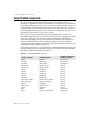
Software license requirements . . . . . . . . . 18-15
DEPLOY . . . . . . . . . . . . . . . . . . . . 18-15
README . . . . . . . . . . . . . . . . . . . 18-16
No-nonsense license agreement . . . . . . 18-16
Third-party product documentation . . . . 18-16
Designing the user interface . . . . . . . . . . 19-15
Analyzing data . . . . . . . . . . . . . . . 19-15
Writing reports. . . . . . . . . . . . . . . . 19-16
Chapter 20
Part II
Developing database applications
Chapter 19
Designing database applications
Using databases . . . . . . . . . . . . . . . .
Types of databases . . . . . . . . . . . . .
Database security. . . . . . . . . . . . . .
Transactions . . . . . . . . . . . . . . . . .
Referential integrity, stored procedures,
and triggers . . . . . . . . . . . . . . . .
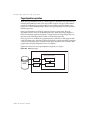
Database architecture . . . . . . . . . . . . .
General structure . . . . . . . . . . . . . .
The user interface form. . . . . . . . .
The data module . . . . . . . . . . . .
Connecting directly to a database
server. . . . . . . . . . . . . . . . . . . .
Using a dedicated file on disk. . . . . . .
Connecting to another dataset . . . . . .
Connecting a client dataset to another
dataset in the same application . . .
Using a multi-tiered architecture . . .
Combining approaches . . . . . . . . . .
19-1
.
.
.
.
. 19-1
. 19-2
. 19-4
. 19-4
.
.
.
.
.
. 19-5
. 19-6
. 19-6
. 19-6
. 19-6
. . 19-8
. . 19-9
. 19-10
. 19-12
. 19-13
. 19-14
xi
Using data controls
20-1
Using common data control features . . . . .
Associating a data control with
a dataset . . . . . . . . . . . . . . . . . .
Changing the associated dataset
at runtime . . . . . . . . . . . . . . . .
Enabling and disabling the data
source . . . . . . . . . . . . . . . . . .
Responding to changes mediated
by the data source . . . . . . . . . . .
Editing and updating data . . . . . . . . .
Enabling editing in controls on
user entry . . . . . . . . . . . . . . . .
Editing data in a control. . . . . . . . .
Disabling and enabling data display . . .
Refreshing data display. . . . . . . . . . .
Enabling mouse, keyboard, and
timer events . . . . . . . . . . . . . . . .
Choosing how to organize the data . . . . . .
Displaying a single record . . . . . . . . .
Displaying data as labels . . . . . . . .
Displaying and editing fields in an
edit box . . . . . . . . . . . . . . . . .
Displaying and editing text in a memo
control . . . . . . . . . . . . . . . . . .
Displaying and editing text in a rich
edit memo control . . . . . . . . . . .
Displaying and editing graphics fields
in an image control. . . . . . . . . . .
Displaying and editing data in list and
combo boxes . . . . . . . . . . . . . .
Handling Boolean field values with
check boxes . . . . . . . . . . . . . . .
Restricting field values with radio
controls . . . . . . . . . . . . . . . . .
Displaying multiple records . . . . . . . .
Viewing and editing data with TDBGrid. . .
Using a grid control in its default state . .
Creating a customized grid. . . . . . . . .
Understanding persistent columns . .
Creating persistent columns . . . . . .
Deleting persistent columns . . . . . .
Arranging the order of persistent
columns . . . . . . . . . . . . . . . . .
. 20-2
. 20-3
. 20-4
. 20-4
. 20-4
. 20-5
.
.
.
.
20-5
20-5
20-6
20-7
.
.
.
.
20-7
20-7
20-7
20-8
. 20-8
. 20-9
. 20-9
20-10
20-10
20-13
20-14
20-14
20-15
20-16
20-17
20-17
20-18
20-19
20-19
Setting column properties at design
time . . . . . . . . . . . . . . . . . .
Defining a lookup list column . . . .
Putting a button in a column . . . .
Restoring default values to a
column . . . . . . . . . . . . . . . .
Displaying ADT and array fields . . . .
Setting grid options . . . . . . . . . . .
Editing in the grid . . . . . . . . . . . .
Controlling grid drawing . . . . . . . .
Responding to user actions at runtime.
Creating a grid that contains other
data-aware controls . . . . . . . . . . . .
Navigating and manipulating records. . .
Choosing navigator buttons
to display . . . . . . . . . . . . . . . .
Hiding and showing navigator
buttons at design time . . . . . . .
Hiding and showing navigator
buttons at runtime . . . . . . . . .
Displaying fly-over help. . . . . . . . .
Using a single navigator for multiple
datasets . . . . . . . . . . . . . . . . .
Chapter 22
. . 20-20
. . 20-21
. . 20-22
.
.
.
.
.
.
.
.
.
.
.
.
Using decision support
components
Overview . . . . . . . . . . . . . . . . . . .
About crosstabs . . . . . . . . . . . . . . . .
One-dimensional crosstabs. . . . . . . .
Multidimensional crosstabs . . . . . . .
Guidelines for using decision support
components . . . . . . . . . . . . . . . . .
Using datasets with decision support
components . . . . . . . . . . . . . . . . .
Creating decision datasets with TQuery
or TTable . . . . . . . . . . . . . . . . .
Creating decision datasets with the
Decision Query editor. . . . . . . . . .
Using decision cubes . . . . . . . . . . . . .
Decision cube properties and events . .
Using the Decision Cube editor . . . . .
Viewing and changing dimension
settings . . . . . . . . . . . . . . . .
Setting the maximum available
dimensions and summaries. . . . .
Viewing and changing design
options . . . . . . . . . . . . . . . .
Using decision sources . . . . . . . . . . . .
Properties and events . . . . . . . . . . .
Using decision pivots. . . . . . . . . . . . .
Decision pivot properties. . . . . . . . .
Creating and using decision grids . . . . .
Creating decision grids . . . . . . . . . .
Using decision grids . . . . . . . . . . .
Opening and closing decision grid
fields. . . . . . . . . . . . . . . . . .
Reorganizing rows and columns in
decision grids. . . . . . . . . . . . .
Drilling down for detail in decision
grids . . . . . . . . . . . . . . . . . .
Limiting dimension selection in
decision grids. . . . . . . . . . . . .
Decision grid properties . . . . . . . . .
Creating and using decision graphs . . . .
Creating decision graphs . . . . . . . . .
Using decision graphs . . . . . . . . . .
The decision graph display. . . . . . . .
Customizing decision graphs . . . . . .
Setting decision graph template
defaults . . . . . . . . . . . . . . . .
Customizing decision graph series .
20-22
20-22
20-24
20-26
20-26
20-27
. . 20-28
. . 20-29
. . 20-30
. . 20-30
. . 20-31
. . 20-31
. . 20-32
Chapter 21
Creating reports with Rave
Reports
Overview . . . . . . . . . . . . . . .
Getting started . . . . . . . . . . . .
The Rave Visual Designer. . . . . .
Component overview . . . . . . . .
VCL/CLX components . . . . .
Engine components. . . . . .
Render components . . . . .
Data connection components
Rave project component . . .
Reporting components. . . . . .
Project components . . . . . .
Data objects . . . . . . . . . .
Standard components . . . .
Drawing components . . . .
Report components . . . . . .
Bar code components. . . . .
Getting more information . . . . . .
21-1
.
.
.
.
.
.
.
.
.
.
.
.
.
.
.
.
.
.
.
.
.
.
.
.
.
.
.
.
.
.
.
.
.
.
.
.
.
.
.
.
.
.
.
.
.
.
.
.
.
.
.
.
.
.
.
.
.
.
.
.
.
.
.
.
.
.
.
.
.
.
.
.
.
.
.
.
.
.
.
.
.
.
.
.
.
.
.
.
.
.
.
.
.
.
.
.
.
.
.
.
.
.
. 21-1
. 21-2
. 21-3
. 21-4
. 21-4
. 21-4
. 21-4
. 21-4
. 21-5
. 21-5
. 21-5
. 21-5
. 21-5
. 21-5
. 21-6
. 21-6
. 21-6
xii
22-1
.
.
.
.
.
.
.
.
22-1
22-2
22-3
22-3
. . 22-4
. . 22-5
. . 22-6
.
.
.
.
.
.
.
.
22-6
22-7
22-7
22-8
. . 22-8
. . 22-9
.
.
.
.
.
.
.
.
. 22-9
. 22-9
. 22-9
22-10
22-10
.22-11
.22-11
.22-11
. .22-11
. 22-12
. 22-12
.
.
.
.
.
.
.
22-12
22-12
22-13
22-13
22-14
22-15
22-16
. 22-17
. 22-18
Decision support components at
runtime . . . . . . . . . . . . . . . . . . . .
Decision pivots at runtime . . . . . . . .
Decision grids at runtime . . . . . . . . .
Decision graphs at runtime . . . . . . . .
Decision support components and memory
control . . . . . . . . . . . . . . . . . . . . .
Setting maximum dimensions,
summaries, and cells . . . . . . . . . . .
Setting dimension state . . . . . . . . . .
Using paged dimensions . . . . . . . . .
.
.
.
.
Using the Eof and Bof properties . .
Eof . . . . . . . . . . . . . . . . . .
Bof . . . . . . . . . . . . . . . . . .
Marking and returning to records . .
The Bookmark property. . . . . .
The GetBookmark method . . . .
The GotoBookmark and
BookmarkValid methods . . . .
The CompareBookmarks method
The FreeBookmark method . . . .
A bookmarking example . . . . .
Searching datasets . . . . . . . . . . . .
Using Locate . . . . . . . . . . . . . .
Using Lookup . . . . . . . . . . . . .
Displaying and editing a subset of data
using filters . . . . . . . . . . . . . . .
Enabling and disabling filtering . . .
Creating filters . . . . . . . . . . . . .
Setting the Filter property. . . . .
Writing an OnFilterRecord event
handler . . . . . . . . . . . . . .
Switching filter event handlers at
runtime . . . . . . . . . . . . . .
Setting filter options. . . . . . . . . .
Navigating records in a filtered
dataset . . . . . . . . . . . . . . . .
Modifying data . . . . . . . . . . . . . .
Editing records. . . . . . . . . . . . .
Adding new records . . . . . . . . .
Inserting records . . . . . . . . . .
Appending records . . . . . . . .
Deleting records . . . . . . . . . . . .
Posting data . . . . . . . . . . . . . .
Canceling changes. . . . . . . . . . .
Modifying entire records . . . . . . .
Calculating fields . . . . . . . . . . . . .
Types of datasets . . . . . . . . . . . . .
Using table type datasets. . . . . . . . .
Advantages of using table type
datasets . . . . . . . . . . . . . . . .
Sorting records with indexes . . . . .
Obtaining information about
indexes . . . . . . . . . . . . . .
Specifying an index with
IndexName . . . . . . . . . . . .
Creating an index with
IndexFieldNames . . . . . . . .
22-19
22-19
22-19
22-20
. 22-20
. 22-20
. 22-21
. 22-21
Chapter 23
Connecting to databases
23-1
Using implicit connections . . . . . . . . .
Controlling connections . . . . . . . . . . .
Connecting to a database server . . . .
Disconnecting from a database server .
Controlling server login . . . . . . . . . . .
Managing transactions . . . . . . . . . . .
Starting a transaction . . . . . . . . . .
Ending a transaction . . . . . . . . . . .
Ending a successful transaction . . .
Ending an unsuccessful transaction
Specifying the transaction isolation
level . . . . . . . . . . . . . . . . . . .
Sending commands to the server . . . . .
Working with associated datasets . . . . .
Closing all datasets without
disconnecting from the server. . . . .
Iterating through the associated
datasets . . . . . . . . . . . . . . . . .
Obtaining metadata . . . . . . . . . . . . .
Listing available tables. . . . . . . . . .
Listing the fields in a table . . . . . . .
Listing available stored procedures . .
Listing available indexes . . . . . . . .
Listing stored procedure parameters. .
.
.
.
.
.
.
.
.
.
.
.
.
.
.
.
.
.
.
.
.
. 23-2
. 23-3
. 23-3
. 23-4
. 23-4
. 23-6
. 23-7
. 23-8
. 23-8
. 23-9
. . . 23-9
. . 23-10
. . 23-12
. . 23-12
.
.
.
.
.
.
.
.
.
.
.
.
.
.
23-13
23-13
23-14
23-14
23-14
23-14
23-15
Chapter 24
Understanding datasets
Using TDataSet descendants . . . . . .
Determining dataset states . . . . . . .
Opening and closing datasets . . . . .
Navigating datasets . . . . . . . . . . .
Using the First and Last methods .
Using the Next and Prior methods .
Using the MoveBy method . . . . .
24-1
.
.
.
.
.
.
.
.
.
.
.
.
.
.
.
.
.
.
.
.
.
.
.
.
.
.
.
.
. 24-2
. 24-3
. 24-4
. 24-5
. 24-6
. 24-7
. 24-7
xiii
.
.
.
.
.
.
.
.
.
.
.
.
.
.
.
.
.
.
. 24-8
. 24-8
. 24-9
. 24-9
. 24-9
24-10
.
.
.
.
.
.
.
.
.
.
.
.
.
.
.
.
.
.
.
.
.
24-10
24-10
24-10
24-10
.24-11
.24-11
24-12
.
.
.
.
.
.
.
.
.
.
.
.
24-13
24-13
24-13
24-14
. . . 24-15
. . . 24-16
. . . 24-16
.
.
.
.
.
.
.
.
.
.
.
.
.
.
.
.
.
.
.
.
.
.
.
.
.
.
.
.
.
.
.
.
.
.
.
.
.
.
.
24-16
24-17
24-18
24-19
24-19
24-20
24-20
24-21
24-21
24-22
24-23
24-24
24-25
. . . 24-26
. . . 24-26
. . . 24-27
. . . 24-27
. . . 24-28
Using Indexes to search for records . . . . 24-28
Executing a search with Goto
methods . . . . . . . . . . . . . . . . . 24-29
Executing a search with Find
methods . . . . . . . . . . . . . . . . . 24-30
Specifying the current record after a
successful search . . . . . . . . . . . . 24-30
Searching on partial keys . . . . . . . . 24-30
Repeating or extending a search . . . . 24-30
Limiting records with ranges . . . . . . . . 24-31
Understanding the differences
between ranges and filters . . . . . . . 24-31
Specifying ranges . . . . . . . . . . . . . 24-31
Modifying a range . . . . . . . . . . . . 24-34
Applying or canceling a range . . . . . 24-34
Creating master/detail relationships. . . . 24-35
Making the table a detail of another
dataset . . . . . . . . . . . . . . . . . . 24-35
Using nested detail tables . . . . . . . . 24-37
Controlling Read/write access to
tables . . . . . . . . . . . . . . . . . . . . . 24-38
Creating and deleting tables . . . . . . . . 24-38
Creating tables . . . . . . . . . . . . . . 24-38
Deleting tables . . . . . . . . . . . . . . 24-41
Emptying tables . . . . . . . . . . . . . . . 24-41
Synchronizing tables . . . . . . . . . . . . . 24-42
Using query-type datasets . . . . . . . . . . . 24-42
Specifying the query . . . . . . . . . . . . . 24-43
Specifying a query using the
SQL property . . . . . . . . . . . . . . 24-44
Specifying a query using the
CommandText property . . . . . . . . 24-44
Using parameters in queries . . . . . . . . 24-45
Supplying parameters at design
time . . . . . . . . . . . . . . . . . . . . 24-45
Supplying parameters at runtime . . . . 24-47
Establishing master/detail relationships
using parameters . . . . . . . . . . . . . . 24-47
Preparing queries. . . . . . . . . . . . . . . 24-48
Executing queries that don’t return a result set .
24-49
Using unidirectional result sets . . . . . . . 24-49
Using stored procedure-type datasets . . . . . 24-50
Working with stored procedure
parameters. . . . . . . . . . . . . . . . . . 24-51
Setting up parameters at design
time . . . . . . . . . . . . . . . . . . . . 24-52
Using parameters at runtime . . . . . . 24-54
Preparing stored procedures . . . . . . . . 24-55
Executing stored procedures that don’t
return a result set . . . . . . . . . . . . . 24-55
Fetching multiple result sets . . . . . . . . 24-56
Chapter 25
xiv
Working with field components
25-1
Dynamic field components . . . . . . . . . .
Persistent field components . . . . . . . . . .
Creating persistent fields . . . . . . . . . .
Arranging persistent fields . . . . . . . . .
Defining new persistent fields . . . . . . .
Defining a data field . . . . . . . . . . .
Defining a calculated field . . . . . . .
Programming a calculated field . . . .
Defining a lookup field . . . . . . . . .
Defining an aggregate field . . . . . . .
Deleting persistent field components . . .
Setting persistent field properties
and events . . . . . . . . . . . . . . . . .
Setting display and edit properties
at design time. . . . . . . . . . . . . .
Setting field component properties
at runtime . . . . . . . . . . . . . . . .
Creating attribute sets for field
components . . . . . . . . . . . . . . .
Associating attribute sets with field
components . . . . . . . . . . . . . . .
Removing attribute associations . . . .
Controlling and masking user
input . . . . . . . . . . . . . . . . . . .
Using default formatting for numeric,
date, and time fields . . . . . . . . . .
Handling events . . . . . . . . . . . . .
Working with field component methods
at runtime . . . . . . . . . . . . . . . . . . .
Displaying, converting, and accessing
field values. . . . . . . . . . . . . . . . . . .
Displaying field component values in
standard controls . . . . . . . . . . . . .
Converting field values . . . . . . . . . . .
Accessing field values with the default
dataset property . . . . . . . . . . . . . .
Accessing field values with a dataset’s
Fields property. . . . . . . . . . . . . . .
Accessing field values with a dataset’s
FieldByName method. . . . . . . . . . .
Setting a default value for a field . . . . . . .
. 25-2
. 25-3
. 25-4
. 25-5
. 25-5
. 25-6
. 25-7
. 25-8
. 25-9
25-10
.25-11
.25-11
.25-11
25-13
25-13
25-14
25-14
25-15
25-15
25-16
25-17
25-18
25-18
25-19
25-20
25-21
25-21
25-22
Working with constraints . . . . . . . . .
Creating a custom constraint . . . . .
Using server constraints . . . . . . . .
Using object fields . . . . . . . . . . . . .
Displaying ADT and array fields . . .
Working with ADT fields . . . . . . .
Using persistent field components
Using the dataset’s FieldByName
method . . . . . . . . . . . . . . .
Using the dateset’s FieldValues
property . . . . . . . . . . . . . .
Using the ADT field’s FieldValues
property . . . . . . . . . . . . . .
Using the ADT field’s Fields
property . . . . . . . . . . . . . .
Working with array fields . . . . . . .
Using persistent fields . . . . . . .
Using the array field’s FieldValues
property . . . . . . . . . . . . . .
Using the array field’s Fields
property . . . . . . . . . . . . . .
Working with dataset fields . . . . . .
Displaying dataset fields . . . . . .
Accessing data in a nested dataset
Working with reference fields. . . . .
Displaying reference fields . . . .
Accessing data in a reference field
.
.
.
.
.
.
.
.
.
.
.
.
.
.
.
.
.
.
.
.
.
25-22
25-22
25-23
25-23
25-24
25-25
25-25
Using TStoredProc . . . . . . . . . . . .
Binding parameters . . . . . . . . . .
Working with Oracle overloaded
stored procedures . . . . . . . . . .
Connecting to databases with
TDatabase . . . . . . . . . . . . . . . .
Associating a database component
with a session. . . . . . . . . . . . .
Understanding database and session
component interactions . . . . . . .
Identifying the database . . . . . . .
Opening a connection using
TDatabase . . . . . . . . . . . . . . .
Using database components in
data modules . . . . . . . . . . . . .
Managing database sessions . . . . . . .
Activating a session . . . . . . . . . .
Specifying default database
connection behavior . . . . . . . . .
Managing database connections . . .
Working with password-protected
Paradox and dBASE tables . . . . .
Specifying Paradox directory
locations. . . . . . . . . . . . . . . .
Working with BDE aliases . . . . . .
Retrieving information about
a session . . . . . . . . . . . . . . . .
Creating additional sessions . . . . .
Naming a session . . . . . . . . . . .
Managing multiple sessions . . . . .
Using transactions with the BDE . . . . . .
Using passthrough SQL . . . . . . . . .
Using local transactions . . . . . . . . .
Using the BDE to cache updates . . . . . .
Enabling BDE-based cached updates . .
Applying BDE-based cached updates. .
Applying cached updates using
a database . . . . . . . . . . . . . . .
Applying cached updates with
dataset component methods . . . .
Creating an OnUpdateRecord event
handler . . . . . . . . . . . . . . . .
Handling cached update errors . . .
Using update objects to update
a dataset . . . . . . . . . . . . . . . . .
Creating SQL statements for update
components . . . . . . . . . . . . . .
Using multiple update objects . . . .
Executing the SQL statements . . . .
. . . 25-25
. . . 25-25
. . . 25-26
. . . 25-26
. . . 25-26
. . . 25-26
. . . 25-27
.
.
.
.
.
.
.
.
.
.
.
.
.
.
.
.
.
.
.
.
.
25-27
25-27
25-27
25-28
25-28
25-28
25-29
Chapter 26
Using the Borland Database Engine 26-1
BDE-based architecture . . . . . . . . . . .
Using BDE-enabled datasets . . . . . .
Associating a dataset with database
and session connections . . . . . .
Caching BLOBs . . . . . . . . . . . .
Obtaining a BDE handle . . . . . . .
Using TTable . . . . . . . . . . . . . . .
Specifying the table type for local
tables . . . . . . . . . . . . . . . . .
Controlling read/write access to
local tables . . . . . . . . . . . . . .
Specifying a dBASE index file . . . .
Renaming local tables . . . . . . . .
Importing data from another table .
Using TQuery. . . . . . . . . . . . . . .
Creating heterogeneous queries. . .
Obtaining an editable result set . . .
Updating read-only result sets . . .
. . . 26-1
. . . 26-2
.
.
.
.
.
.
.
.
. 26-3
. 26-4
. 26-4
. 26-5
. . . 26-5
.
.
.
.
.
.
.
.
.
.
.
.
.
.
.
.
. 26-6
. 26-6
. 26-8
. 26-8
. 26-9
. 26-9
26-10
26-11
xv
. .26-11
. 26-12
. 26-12
. 26-12
. 26-13
. 26-13
. 26-14
. 26-15
. 26-16
. 26-16
. 26-18
. 26-18
. 26-19
. 26-21
. 26-24
. 26-25
.
.
.
.
.
.
.
.
.
.
26-27
26-28
26-29
26-29
26-31
26-32
26-32
26-33
26-34
26-35
. 26-36
. 26-36
. 26-37
. 26-38
. 26-40
. 26-41
. 26-45
. 26-46
Using TBatchMove. . . . . . . . . . . . .
Creating a batch move component . .
Specifying a batch move mode . . . .
Appending records . . . . . . . . .
Updating records . . . . . . . . . .
Appending and updating records
Copying datasets . . . . . . . . . .
Deleting records. . . . . . . . . . .
Mapping data types . . . . . . . . . .
Executing a batch move . . . . . . . .
Handling batch move errors . . . . .
The Data Dictionary . . . . . . . . . . . .
Tools for working with the BDE . . . . .
.
.
.
.
.
.
.
.
.
.
.
.
.
.
.
.
.
.
.
.
.
.
.
.
.
.
.
.
.
.
.
.
.
.
.
.
.
.
.
26-49
26-49
26-50
26-50
26-50
26-51
26-51
26-51
26-51
26-52
26-52
26-53
26-55
Using Command objects . . . . . . . . . .
Specifying the command . . . . . . . .
Using the Execute method . . . . . . .
Canceling commands . . . . . . . . . .
Retrieving result sets with commands
Handling command parameters . . . .
Overview of ADO components . . . . . . .
Connecting to ADO data stores . . . . . . .
Connecting to a data store using
TADOConnection. . . . . . . . . . . . .
Accessing the connection object . . . .
Fine-tuning a connection . . . . . . . . .
Forcing asynchronous connections . .
Controlling time-outs. . . . . . . . . .
Indicating the types of operations
the connection supports . . . . . . .
Specifying whether the connection
automatically initiates transactions .
Accessing the connection’s commands .
ADO connection events . . . . . . . . . .
Events when establishing a
connection . . . . . . . . . . . . . . .
Events when disconnecting . . . . . .
Events when managing transactions .
Other events . . . . . . . . . . . . . . .
Using ADO datasets . . . . . . . . . . . . . .
Connecting an ADO dataset to a
data store . . . . . . . . . . . . . . .
Working with record sets . . . . . . .
Filtering records based on
bookmarks . . . . . . . . . . . . . . .
Fetching records asynchronously . . .
Using batch updates . . . . . . . . . .
Loading data from and saving
data to files. . . . . . . . . . . . . . .
Using TADODataSet . . . . . . . . . . . .
Types of unidirectional datasets . . . . . .
Connecting to the database server . . . .
Setting up TSQLConnection . . . . . .
Identifying the driver . . . . . . . .
Specifying connection parameters .
Naming a connection description .
Using the Connection Editor . . . .
Specifying what data to display . . . . . .
Representing the results of a query . .
Representing the records in a table . .
Representing a table using
TSQLDataSet . . . . . . . . . . . .
Representing a table using
TSQLTable . . . . . . . . . . . . .
Representing the results of a stored
procedure. . . . . . . . . . . . . . . .
Fetching the data . . . . . . . . . . . . . .
Preparing the dataset . . . . . . . . . .
Fetching multiple datasets . . . . . . .
Executing commands that do not
return records . . . . . . . . . . . . . . .
Specifying the command to execute. .
Executing the command . . . . . . . .
Creating and modifying server
metadata . . . . . . . . . . . . . . . .
Setting up master/detail linked cursors .
Accessing schema information . . . . . .
Fetching metadata into a
unidirectional dataset . . . . . . . .
Fetching data after using the
dataset for metadata . . . . . . . .
The structure of metadata
datasets . . . . . . . . . . . . . . .
Debugging dbExpress applications . . . .
Using TSQLMonitor to monitor
SQL commands . . . . . . . . . . . .
Using a callback to monitor
SQL commands . . . . . . . . . . . .
27-1
. 27-3
. 27-5
. 27-5
. 27-5
. 27-6
. . 27-6
. . 27-7
. . 27-7
. . 27-8
.
.
.
.
.
27-18
27-18
27-19
27-19
27-20
27-20
.
.
.
.
.
.
.
.
.
.
.
.
.
.
.
.
.
.
.
.
.
.
.
.
.
.
.
.
.
.
Using unidirectional datasets
. . 27-2
. . 27-3
.
.
.
.
.
.
.
.
.
.
.
Chapter 28
Chapter 27
Working with ADO components
.
.
.
.
.
.
. 27-8
. 27-8
. 27-9
. 27-9
. 27-9
. 27-10
. 27-11
. 27-11
. 27-12
. 27-13
. 27-15
. 27-16
xvi
28-1
28-2
28-2
28-3
28-3
28-4
28-4
28-5
28-6
28-6
28-7
. . . 28-7
. . . 28-7
.
.
.
.
.
.
.
.
.
.
.
.
28-8
28-8
28-9
28-9
. . 28-10
. . 28-10
. . .28-11
. . .28-11
. . 28-12
. . 28-13
. . 28-13
. . 28-14
. . 28-14
. . 28-19
. . 28-19
. . 28-20
Chapter 29
Using client datasets
Working with data using a client dataset . .
Navigating data in client datasets . . . .
Limiting what records appear. . . . . . .
Editing data . . . . . . . . . . . . . . . . .
Undoing changes . . . . . . . . . . . .
Saving changes . . . . . . . . . . . . .
Constraining data values . . . . . . . . .
Specifying custom constraints. . . . .
Sorting and indexing. . . . . . . . . . . .
Adding a new index . . . . . . . . . .
Deleting and switching indexes . . . .
Using indexes to group data. . . . . .
Representing calculated values . . . . . .
Using internally calculated fields
in client datasets. . . . . . . . . . . .
Using maintained aggregates . . . . . . .
Specifying aggregates . . . . . . . . .
Aggregating over groups
of records. . . . . . . . . . . . . . . .
Obtaining aggregate values . . . . . .
Copying data from another dataset . . .
Assigning data directly. . . . . . . . .
Cloning a client dataset cursor . . . .
Adding application-specific information
to the data . . . . . . . . . . . . . . . . .
Using a client dataset to cache updates . . .
Overview of using cached updates. . . .
Choosing the type of dataset for
caching updates. . . . . . . . . . . . . .
Indicating what records are modified . .
Updating records . . . . . . . . . . . . . .
Applying updates. . . . . . . . . . . .
Intervening as updates are applied . .
Reconciling update errors . . . . . . .
Using a client dataset with a provider . . . .
Specifying a provider . . . . . . . . . . .
Requesting data from the source
dataset or document . . . . . . . . . . .
Incremental fetching . . . . . . . . . .
Fetch-on-demand . . . . . . . . . . . .
Getting parameters from the source
dataset . . . . . . . . . . . . . . . . . . .
Passing parameters to the source
dataset . . . . . . . . . . . . . . . . . . .
Sending query or stored procedure
parameters . . . . . . . . . . . . . . .
Limiting records with parameters . .
Handling constraints from the server .
Refreshing records. . . . . . . . . . . .
Communicating with providers using
custom events . . . . . . . . . . . . .
Overriding the source dataset . . . . .
Using a client dataset with file-based
data . . . . . . . . . . . . . . . . . . . . .
Creating a new dataset . . . . . . . . .
Loading data from a file or stream . .
Merging changes into data . . . . . . .
Saving data to a file or stream . . . . .
Using a simple dataset . . . . . . . . . . .
When to use TSimpleDataSet . . . . .
Setting up a simple dataset . . . . . . .
29-1
.
.
.
.
.
.
.
.
.
.
.
.
.
. 29-2
. 29-2
. 29-2
. 29-5
. 29-5
. 29-6
. 29-7
. 29-7
. 29-8
. 29-8
. 29-9
. 29-9
29-10
.
.
.
.
.
.
.
.
Using provider components
Determining the source of data . . . . . . .
Using a dataset as the source of
the data . . . . . . . . . . . . . . . . . .
Using an XML document as the source
of the data . . . . . . . . . . . . . . . .
Communicating with the client dataset . .
Choosing how to apply updates using
a dataset provider . . . . . . . . . . . . . .
Controlling what information is included
in data packets. . . . . . . . . . . . . . . .
Specifying what fields appear in data
packets . . . . . . . . . . . . . . . . . .
Setting options that influence the data
packets . . . . . . . . . . . . . . . . . .
Adding custom information to data
packets . . . . . . . . . . . . . . . . . .
Responding to client data requests . . . . .
Responding to client update requests . . .
Editing delta packets before updating
the database . . . . . . . . . . . . . . .
Influencing how updates are applied . .
Screening individual updates . . . . . .
Resolving update errors on the
provider. . . . . . . . . . . . . . . . . .
Applying updates to datasets that
do not represent a single table . . . . .
Responding to client-generated events . . .
Handling server constraints . . . . . . . . .
29-13
29-14
29-14
29-14
29-15
. 29-15
. 29-16
. 29-17
.
.
.
.
.
.
.
.
. . 29-31
. . 29-32
.
.
.
.
.
.
.
.
29-33
29-33
29-34
29-34
29-35
29-35
29-36
29-36
Chapter 30
. 29-11
. 29-11
. 29-12
.
.
.
.
.
. . 29-30
. . 29-31
29-18
29-19
29-20
29-20
29-21
29-23
29-24
29-25
. 29-26
. 29-26
. 29-27
. 29-27
. 29-28
. 29-29
. 29-29
xvii
30-1
. . 30-2
. . 30-2
. . 30-2
. . 30-3
. . 30-4
. . 30-4
. . 30-4
. . 30-5
. . 30-6
. . 30-7
. . 30-8
. . 30-9
. 30-10
. .30-11
. .30-11
. 30-12
. 30-12
. 30-13
Chapter 31
Creating multi-tiered applications
Advantages of the multi-tiered database
model . . . . . . . . . . . . . . . . . . . . .
Understanding multi-tiered database
applications . . . . . . . . . . . . . . . . . .
Overview of a three-tiered application. .
The structure of the client application . .
The structure of the application server. .
The contents of the remote
data module . . . . . . . . . . . . . .
Using transactional data modules . .
Pooling remote data modules . . . . .
Choosing a connection protocol . . . . .
Using DCOM connections . . . . . . .
Using Socket connections . . . . . . .
Using Web connections. . . . . . . . .
Using SOAP connections. . . . . . . .
Building a multi-tiered application . . . . .
Creating the application server. . . . . . . .
Setting up the remote data module. . . .
Configuring TRemoteDataModule . .
Configuring TMTSDataModule . . . .
Configuring TSoapDataModule. . . .
Extending the application server’s
interface . . . . . . . . . . . . . . . . . .
Adding callbacks to the application
server’s interface . . . . . . . . . . .
Extending a transactional application
server’s interface . . . . . . . . . . .
Managing transactions in multi-tiered
applications . . . . . . . . . . . . . . . .
Supporting master/detail
relationships. . . . . . . . . . . . . . . .
Supporting state information in remote
data modules . . . . . . . . . . . . . . .
Using multiple remote data modules . .
Registering the application server . . . . . .
Creating the client application . . . . . . . .
Connecting to the application server. . .
Specifying a connection using
DCOM . . . . . . . . . . . . . . . . .
Specifying a connection using
sockets . . . . . . . . . . . . . . . . .
Specifying a connection using
HTTP . . . . . . . . . . . . . . . . . .
Specifying a connection using
SOAP . . . . . . . . . . . . . . . . . .
Brokering connections . . . . . . . . .
31-1
. . 31-2
.
.
.
.
. 31-2
. 31-3
. 31-4
. 31-5
.
.
.
.
.
.
.
.
.
.
.
.
.
.
. 31-6
. 31-7
. 31-8
. 31-9
. 31-9
. 31-9
31-10
31-11
31-11
31-12
31-13
31-13
31-15
31-16
. 31-16
. 31-17
. 31-17
. 31-17
. 31-18
.
.
.
.
.
31-19
31-21
31-22
31-22
31-23
. 31-24
. 31-24
. 31-25
Managing server connections . . . . . . .
Connecting to the server . . . . . . . .
Dropping or changing a server
connection . . . . . . . . . . . . . . .
Calling server interfaces . . . . . . . . . .
Using early binding with DCOM . . .
Using dispatch interfaces with
TCP/IP or HTTP . . . . . . . . . . . .
Calling the interface of a SOAP-based
server . . . . . . . . . . . . . . . . . .
Connecting to an application server
that uses multiple data modules . . . . .
Writing Web-based client applications . . . .
Distributing a client application as an
ActiveX control . . . . . . . . . . . . . .
Creating an Active Form for the
client application . . . . . . . . . . . .
Building Web applications using
InternetExpress . . . . . . . . . . . . . .
Building an InternetExpress
application . . . . . . . . . . . . . . . . .
Using the javascript libraries . . . . . .
Granting permission to access and
launch the application server . . . . .
Using an XML broker . . . . . . . . . . . .
Fetching XML data packets . . . . . . .
Applying updates from XML delta
packets . . . . . . . . . . . . . . . . .
Creating Web pages with an
InternetExpress page producer . . . . .
Using the Web page editor . . . . . . .
Setting Web item properties . . . . . .
Customizing the InternetExpress
page producer template . . . . . . . .
31-27
31-27
31-28
31-28
31-29
31-29
31-30
31-30
31-31
31-32
31-33
31-33
31-34
31-35
31-36
31-36
31-36
31-37
31-39
31-39
31-40
31-41
Chapter 32
Using XML in database
applications
Defining transformations . . . . . . . .
Mapping between XML nodes and
data packet fields . . . . . . . . . .
Using XMLMapper . . . . . . . . . .
Loading an XML schema or data
packet . . . . . . . . . . . . . . .
Defining mappings . . . . . . . .
Generating transformation files .
. 31-26
. 31-27
xviii
32-1
. . . . 32-1
. . . . 32-2
. . . . 32-4
. . . . 32-4
. . . . 32-5
. . . . 32-6
Converting XML documents into data
packets . . . . . . . . . . . . . . . . . . .
Specifying the source XML document .
Specifying the transformation . . . . .
Obtaining the resulting data packet . .
Converting user-defined nodes . . . . .
Using an XML document as the source
for a provider . . . . . . . . . . . . . . . .
Using an XML document as the client of
a provider . . . . . . . . . . . . . . . . . .
Fetching an XML document from
a provider . . . . . . . . . . . . . . . .
Applying updates from an XML
document to a provider . . . . . . . .
.
.
.
.
.
.
.
.
.
.
Chapter 34
. 32-6
. 32-6
. 32-7
. 32-7
. 32-7
Using Web Broker
Creating Web server applications with
Web Broker. . . . . . . . . . . . . . . . . .
The Web module. . . . . . . . . . . . . .
The Web Application object . . . . . . .
The structure of a Web Broker application .
The Web dispatcher. . . . . . . . . . . . . .
Adding actions to the dispatcher . . . .
Dispatching request messages . . . . . .
Action items . . . . . . . . . . . . . . . . . .
Determining when action items fire. . .
The target URL . . . . . . . . . . . . .
The request method type . . . . . . .
Enabling and disabling action items.
Choosing a default action item . . . .
Responding to request messages with
action items. . . . . . . . . . . . . . . .
Sending the response . . . . . . . . .
Using multiple action items . . . . .
Accessing client request information . . . .
Properties that contain request header
information. . . . . . . . . . . . . . . .
Properties that identify the target . .
Properties that describe the Web
client . . . . . . . . . . . . . . . . . .
Properties that identify the purpose
of the request . . . . . . . . . . . . .
Properties that describe the expected
response . . . . . . . . . . . . . . . .
Properties that describe the content .
The content of HTTP request messages .
Creating HTTP response messages . . . . .
Filling in the response header . . . . . .
Indicating the response status . . . .
Indicating the need for client action .
Describing the server application . .
Describing the content . . . . . . . .
Setting the response content . . . . . . .
Sending the response . . . . . . . . . . .
Generating the content of response
messages . . . . . . . . . . . . . . . . . . .
Using page producer components. . . .
HTML templates . . . . . . . . . . . .
Specifying the HTML template. . . .
Converting HTML-transparent
tags . . . . . . . . . . . . . . . . . .
. . . 32-8
. . . 32-9
. . . 32-9
. . 32-11
Part III
Writing Internet applications
Chapter 33
Creating Internet server
applications
About Web Broker and WebSnap . . . . . . .
Terminology and standards. . . . . . . . . . .
Parts of a Uniform Resource Locator. . . .
URI vs. URL . . . . . . . . . . . . . . . .
HTTP request header information . . . . .
HTTP server activity. . . . . . . . . . . . . . .
Composing client requests . . . . . . . . .
Serving client requests . . . . . . . . . . . .
Responding to client requests . . . . . . . .
Types of Web server applications . . . . . . .
ISAPI and NSAPI . . . . . . . . . . . . .
CGI stand-alone. . . . . . . . . . . . . .
Apache . . . . . . . . . . . . . . . . . . .
Web App Debugger. . . . . . . . . . . .
Converting Web server application
target types . . . . . . . . . . . . . . . . .
Debugging server applications . . . . . . . . .
Using the Web Application Debugger . . .
Launching your application with the
Web Application Debugger . . . . . .
Converting your application to another
type of Web server application . . . .
Debugging Web applications that
are DLLs . . . . . . . . . . . . . . . . . . .
User rights necessary for DLL
debugging . . . . . . . . . . . . . . . .
33-1
. 33-1
. 33-3
. 33-3
. 33-4
. 33-4
. 33-5
. 33-5
. 33-5
. 33-6
. 33-6
. 33-6
. 33-6
. 33-7
. 33-7
. 33-8
. 33-9
. 33-9
. 33-9
33-10
33-10
33-10
xix
34-1
.
.
.
.
.
.
.
.
.
.
.
.
.
.
.
.
.
.
.
.
.
.
.
.
.
.
34-1
34-2
34-3
34-3
34-5
34-5
34-5
34-6
34-6
34-6
34-7
34-7
34-7
.
.
.
.
.
.
.
.
34-8
34-8
34-9
34-9
. . 34-9
. . 34-9
. 34-10
. 34-10
.
.
.
.
.
.
.
.
.
.
.
34-10
.34-11
.34-11
.34-11
.34-11
34-12
34-12
34-12
34-12
34-13
34-13
.
.
.
.
34-13
34-14
34-14
34-15
. 34-16
Using page producers from an
action item . . . . . . . . . . . . . .
Chaining page producers together .
Using database information in responses .
Adding a session to the Web module .
Representing database information
in HTML . . . . . . . . . . . . . . . . .
Using dataset page producers . . . .
Using table producers . . . . . . . .
Specifying the table attributes . . . .
Specifying the row attributes . . . .
Specifying the columns. . . . . . . .
Embedding tables in HTML
documents . . . . . . . . . . . . . .
Setting up a dataset table producer .
Setting up a query table producer .
.
.
.
.
.
.
.
.
34-16
34-17
34-18
34-18
.
.
.
.
.
.
.
.
.
.
.
.
34-19
34-19
34-20
34-20
34-20
34-20
User access rights . . . . . . . . . . . . . .
Dynamically displaying fields as edit
or text boxes . . . . . . . . . . . . . .
Hiding fields and their contents . . . .
Preventing page access . . . . . . . . .
Server-side scripting in WebSnap . . . . . . .
Active scripting . . . . . . . . . . . . . . .
Script engine . . . . . . . . . . . . . . . . .
Script blocks . . . . . . . . . . . . . . . . .
Creating script . . . . . . . . . . . . . . . .
Wizard templates . . . . . . . . . . . .
TAdapterPageProducer . . . . . . . . .
Editing and viewing script . . . . . . . . .
Including script in a page. . . . . . . . . .
Script objects . . . . . . . . . . . . . . . . .
Dispatching requests and responses . . . . .
Dispatcher components. . . . . . . . . . .
Adapter dispatcher operation . . . . . . .
Using adapter components to
generate content . . . . . . . . . . . .
Receiving adapter requests and
generating responses . . . . . . . . .
Image request . . . . . . . . . . . . . .
Image response. . . . . . . . . . . . . .
Dispatching action items . . . . . . . . . .
Page dispatcher operation . . . . . . . . .
. . 34-21
. . 34-21
. . 34-21
Chapter 35
Creating Web Server applications
using WebSnap
Fundamental WebSnap components. .
Web modules . . . . . . . . . . . . .
Web application module types .
Web page modules . . . . . . . .
Web data modules . . . . . . . .
Adapters. . . . . . . . . . . . . . . .
Fields . . . . . . . . . . . . . . . .
Actions . . . . . . . . . . . . . . .
Errors. . . . . . . . . . . . . . . .
Records. . . . . . . . . . . . . . .
Page producers . . . . . . . . . . . .
Creating Web server applications with
WebSnap . . . . . . . . . . . . . . . .
Selecting a server type . . . . . . . .
Specifying application module
components . . . . . . . . . . . . .
Selecting Web application module
options . . . . . . . . . . . . . . . .
Advanced HTML design . . . . . . . .
Manipulating server-side script in
HTML files . . . . . . . . . . . . .
Login support . . . . . . . . . . . . . .
Adding login support . . . . . . . .
Using the sessions service . . . . . .
Login pages . . . . . . . . . . . . . .
Setting pages to require logins . . .
.
.
.
.
.
.
.
.
.
.
.
.
.
.
.
.
.
.
.
.
.
.
35-1
.
.
.
.
.
.
.
.
.
.
.
.
.
.
.
.
.
.
.
.
.
.
. 35-2
. 35-2
. 35-3
. 35-4
. 35-5
. 35-5
. 35-6
. 35-6
. 35-6
. 35-6
. 35-6
Creating Web server applications
using IntraWeb
. . . . 35-10
. . . . 35-11
.
.
.
.
.
.
.
.
.
.
.
.
35-23
35-25
35-26
35-27
35-27
35-28
36-1
Using IntraWeb components. . . . . . . . . . . 36-2
Getting started with IntraWeb . . . . . . . . . . 36-3
Creating a new IntraWeb application . . . . 36-4
Editing the main form . . . . . . . . . . . . 36-4
Writing an event handler for the button . . 36-5
Running the completed application . . . . . 36-6
Using IntraWeb with Web Broker and WebSnap . .
36-7
For more information. . . . . . . . . . . . . . . 36-8
. . . . . 35-9
.
.
.
.
.
.
35-18
35-18
35-19
35-19
35-20
35-20
35-20
35-21
35-21
35-21
35-21
35-21
35-22
35-22
35-23
35-23
Chapter 36
. . . . . 35-7
. . . . . 35-8
.
.
.
.
.
.
35-17
Chapter 37
35-12
35-13
35-13
35-14
35-15
35-17
Working with XML documents
Using the Document Object Model . . .
Working with XML components . . . .
Using TXMLDocument . . . . . . . .
Working with XML nodes . . . . . .
Working with a node’s value . . .
Working with a node’s attributes
Adding and deleting child nodes
xx
37-1
.
.
.
.
.
.
.
.
.
.
.
.
.
.
.
.
.
.
.
.
.
.
.
.
.
.
.
.
37-2
37-4
37-4
37-4
37-5
37-5
37-6
Chapter 39
Abstracting XML documents with the
Data Binding wizard. . . . . . . . . . . . . . . 37-6
Using the XML Data Binding wizard . . . . 37-8
Using code that the XML Data Binding
wizard generates . . . . . . . . . . . . . . . 37-9
Working with sockets
Implementing services . . . . . . . . . . . .
Understanding service protocols . . . .
Communicating with applications. .
Services and ports . . . . . . . . . . . . .
Types of socket connections . . . . . . . . .
Client connections. . . . . . . . . . . . .
Listening connections . . . . . . . . . . .
Server connections . . . . . . . . . . . .
Describing sockets . . . . . . . . . . . . . .
Describing the host . . . . . . . . . . . .
Choosing between a host name and
an IP address . . . . . . . . . . . . .
Using ports . . . . . . . . . . . . . . . . .
Using socket components . . . . . . . . . .
Getting information about the
connection . . . . . . . . . . . . . . . .
Using client sockets . . . . . . . . . . . .
Specifying the desired server . . . . .
Forming the connection . . . . . . . .
Getting information about the
connection . . . . . . . . . . . . . .
Closing the connection . . . . . . . .
Using server sockets . . . . . . . . . . .
Specifying the port. . . . . . . . . . .
Listening for client requests . . . . .
Connecting to clients . . . . . . . . .
Closing server connections . . . . . .
Responding to socket events. . . . . . . . .
Error events . . . . . . . . . . . . . . . .
Client events . . . . . . . . . . . . . . . .
Server events. . . . . . . . . . . . . . . .
Events when listening . . . . . . . . .
Events with client connections . . . .
Reading and writing over socket
connections . . . . . . . . . . . . . . . . .
Non-blocking connections . . . . . . . .
Reading and writing events . . . . .
Blocking connections . . . . . . . . . . .
Chapter 38
Using Web Services
Understanding invokable interfaces . . . . .
Using nonscalar types in invokable
interfaces . . . . . . . . . . . . . . . . .
Registering nonscalar types . . . . . .
Using remotable objects . . . . . . . .
Representing attachments . . . . . . .
Managing the lifetime of remotable
objects . . . . . . . . . . . . . . . . .
Remotable object example . . . . . . .
Writing servers that support Web
Services . . . . . . . . . . . . . . . . . . . .
Building a Web Service server . . . . . .
Using the SOAP application wizard . . .
Adding new Web Services. . . . . . . . .
Editing the generated code . . . . . .
Using a different base class . . . . . .
Using the Web Services Importer . . . . .
Browsing for Business services . . . . . .
Understanding UDDI . . . . . . . . .
Using the UDDI browser. . . . . . . .
Defining and using SOAP headers . . . .
Defining header classes . . . . . . . .
Sending and receiving headers . . . .
Communicating the structure of your
headers to other applications . . . .
Creating custom exception classes for
Web Services . . . . . . . . . . . . . . .
Generating WSDL documents for a
Web Service application . . . . . . . . .
Writing clients for Web Services . . . . . . .
Importing WSDL documents . . . . . . .
Calling invokable interfaces. . . . . . . .
Obtaining an invokable interface
from the generated function . . . . .
Using a remote interfaced object . . .
Processing headers in client applications
38-1
. . 38-2
.
.
.
.
. 38-4
. 38-5
. 38-6
. 38-7
. . 38-7
. . 38-7
.
.
.
.
.
.
.
.
.
.
.
.
.
. 38-9
. 38-9
38-10
38-11
38-12
38-12
38-13
38-14
38-15
38-15
38-16
38-16
38-16
. 38-17
. 38-18
.
.
.
.
38-19
38-20
38-20
38-20
. 38-21
. 38-21
. 38-23
xxi
39-1
.
.
.
.
.
.
.
.
.
.
.
.
.
.
.
.
.
.
.
.
39-1
39-2
39-2
39-2
39-3
39-3
39-3
39-3
39-4
39-4
. . 39-5
. . 39-5
. . 39-6
.
.
.
.
.
.
.
.
39-6
39-6
39-7
39-7
.
.
.
.
.
.
.
.
.
.
.
.
.
. 39-7
. 39-7
. 39-7
. 39-8
. 39-8
. 39-8
. 39-8
. 39-8
. 39-9
. 39-9
. 39-9
. 39-9
39-10
.
.
.
.
39-10
39-10
.39-11
.39-11
Part IV
CoClasses . . . . . . . . . . . . . . .
Type definitions . . . . . . . . . . .
Modules. . . . . . . . . . . . . . . .
Using the Type Library editor . . . . .
Valid types . . . . . . . . . . . . . .
Using Delphi or IDL syntax . . . .
Creating a new type library. . . . .
Opening an existing type library. .
Adding an interface to the type
library . . . . . . . . . . . . . . . .
Modifying an interface using the
type library . . . . . . . . . . . . .
Adding properties and methods to
an interface or dispinterface . . .
Adding a CoClass to the type
library . . . . . . . . . . . . . . . .
Adding an interface to a CoClass .
Adding an enumeration to the
type library . . . . . . . . . . . . .
Adding an alias to the type library
Adding a record or union to the
type library . . . . . . . . . . . . .
Adding a module to the type
library . . . . . . . . . . . . . . . .
Saving and registering type
library information. . . . . . . . .
Apply Updates dialog. . . . . . . .
Saving a type library . . . . . . . .
Refreshing the type library . . . . .
Registering the type library. . . . .
Exporting an IDL file . . . . . . . .
Deploying type libraries . . . . . . . . . .
Developing COM-based applications
Chapter 40
Overview of COM technologies
40-1
COM as a specification and
implementation . . . . . . . . . .
COM extensions . . . . . . . . . .
Parts of a COM application . . . . . . . .
COM interfaces . . . . . . . . . . . . .
The fundamental COM interface,
IUnknown . . . . . . . . . . . . .
COM interface pointers . . . . . .
COM servers . . . . . . . . . . . . . .
CoClasses and class factories . . .
In-process, out-of-process, and
remote servers . . . . . . . . . . .
The marshaling mechanism . . . .
Aggregation . . . . . . . . . . . . .
COM clients . . . . . . . . . . . . . . .
COM extensions . . . . . . . . . . . . . .
Automation servers . . . . . . . . . .
Active Server Pages . . . . . . . . . .
ActiveX controls . . . . . . . . . . . .
Active Documents . . . . . . . . . . .
Transactional objects . . . . . . . . . .
Type libraries . . . . . . . . . . . . . .
The content of type libraries . . . .
Creating type libraries . . . . . . .
When to use type libraries . . . . .
Accessing type libraries . . . . . .
Benefits of using type libraries . .
Using type library tools . . . . . .
Implementing COM objects with
wizards . . . . . . . . . . . . . . . . . .
Code generated by wizards . . . . . .
.
.
.
.
.
.
.
.
.
.
.
.
. 40-2
. 40-2
. 40-3
. 40-3
.
.
.
.
.
.
.
.
.
.
.
.
. 40-4
. 40-5
. 40-5
. 40-6
.
.
.
.
.
.
.
.
.
.
.
.
.
.
.
.
.
.
.
.
.
.
.
.
.
.
.
.
.
.
.
.
.
.
.
.
.
.
.
.
.
.
.
.
.
.
.
.
.
.
.
. 40-7
. 40-8
. 40-9
40-10
40-10
40-12
40-13
40-13
40-14
40-15
40-16
40-16
40-17
40-17
40-18
40-18
40-19
Importing type library information . . . .
Using the Import Type Library dialog
Using the Import ActiveX dialog . . .
Code generated when you import
type library information . . . . . . .
Controlling an imported object . . . . . .
Using component wrappers . . . . . .
ActiveX wrappers . . . . . . . . . .
Automation object wrappers . . . .
Using data-aware ActiveX controls . .
Example: Printing a document with
Microsoft Word . . . . . . . . . . . .
Preparing Delphi for this example .
Importing the Word type library . .
41-1
.
.
.
.
.
.
.
.
.
.
.
.
.
.
.
.
.
.
.
.
.
.
.
.
.
.
.
.
.
.
.
.
.
.
.
.
.
.
.
.
.
.
.
.
.
.
.
.
.
.
.
.
.
.
41-10
41-10
.41-11
.41-11
41-12
41-13
41-19
41-20
. . 41-21
. . 41-21
. . 41-22
. . 41-23
. . 41-23
. . 41-24
. . 41-24
. . 41-24
. . 41-25
.
.
.
.
.
.
.
.
.
.
.
.
.
.
Creating COM clients
Chapter 41
Type Library editor . . . . . . . . .
Parts of the Type Library editor.
Toolbar . . . . . . . . . . . . .
Object list pane . . . . . . . .
Status bar . . . . . . . . . . .
Pages of type information . .
Type library elements . . . . . .
Interfaces. . . . . . . . . . . .
Dispinterfaces . . . . . . . . .
.
.
.
.
.
.
.
.
41-25
41-26
41-26
41-26
41-27
41-27
41-27
Chapter 42
. . . 40-19
. . . 40-22
Working with type libraries
.
.
.
.
.
.
.
.
. 41-2
. 41-3
. 41-3
. 41-5
. 41-5
. 41-6
. 41-8
. 41-9
. 41-9
xxii
42-1
. . . 42-2
. . . 42-3
. . . 42-4
.
.
.
.
.
.
.
.
.
.
.
.
.
.
.
.
.
.
42-5
42-6
42-6
42-6
42-7
42-8
. . . 42-9
. . 42-10
. . 42-10
Using a VTable or dispatch interface
object to control Microsoft Word . .
Cleaning up the example . . . . . . .
Writing client code based on type library
definitions . . . . . . . . . . . . . . . . .
Connecting to a server . . . . . . . . .
Controlling an Automation server
using a dual interface . . . . . . . . .
Controlling an Automation server
using a dispatch interface . . . . . .
Handling events in an automation
controller . . . . . . . . . . . . . . . .
Creating clients for servers that do not
have a type library . . . . . . . . . . . . . .
Using .NET Assemblies with Delphi . . . .
Requirements for COM
Interoperability . . . . . . . . . . . . . .
.NET components and type libraries . . .
Accessing user-defined .NET
components . . . . . . . . . . . . . . . .
. 42-11
. 42-12
. 42-13
. 42-13
. 42-13
. 42-14
. 42-14
. 42-16
. 42-17
. 42-17
. 42-18
. 42-20
Chapter 43
Creating simple COM servers
Overview of creating a COM object . . . .
Designing a COM object . . . . . . . . . .
Using the COM object wizard . . . . . . .
Using the Automation object wizard . . .
COM object instancing types . . . . . .
Choosing a threading model . . . . . .
Writing an object that supports the
free threading model . . . . . . . .
Writing an object that supports the
apartment threading model . . . .
Writing an object that supports the
neutral threading model . . . . . .
Defining a COM object’s interface . . . . .
Adding a property to the object’s
interface . . . . . . . . . . . . . . . . .
Adding a method to the object’s
interface . . . . . . . . . . . . . . . . .
Exposing events to clients . . . . . . . .
Managing events in your
Automation object . . . . . . . . .
Automation interfaces . . . . . . . . . . . .
Dual interfaces . . . . . . . . . . . . . .
Dispatch interfaces . . . . . . . . . . . .
Custom interfaces . . . . . . . . . . . .
43-1
.
.
.
.
.
.
.
.
.
.
.
.
. 43-2
. 43-2
. 43-3
. 43-5
. 43-6
. 43-6
. . . 43-8
. . . 43-9
. . . 43-9
. . . 43-9
. . 43-10
. . 43-10
. . 43-11
.
.
.
.
.
.
.
.
.
.
43-12
43-13
43-13
43-14
43-15
Marshaling data . . . . . . . . . . . . . .
Automation compatible types . . . .
Type restrictions for automatic
marshaling . . . . . . . . . . . . . .
Custom marshaling . . . . . . . . . .
Registering a COM object . . . . . . . .
Registering an in-process server . . .
Registering an out-of-process server
Testing and debugging the application.
. . . 43-15
. . . 43-16
.
.
.
.
.
.
.
.
.
.
.
.
.
.
.
.
.
.
43-16
43-17
43-17
43-17
43-17
43-18
Creating an Active Server Object . . . . . .
Using the ASP intrinsics . . . . . . . . .
Application . . . . . . . . . . . . . . .
Request . . . . . . . . . . . . . . . . .
Response . . . . . . . . . . . . . . . .
Session . . . . . . . . . . . . . . . . .
Server . . . . . . . . . . . . . . . . . .
Creating ASPs for in-process or out-ofprocess servers . . . . . . . . . . . . . .
Registering an Active Server Object . . . .
Registering an in-process server . . . . .
Registering an out-of-process server . .
Testing and debugging the Active Server
Page application. . . . . . . . . . . . . . .
.
.
.
.
.
.
.
.
.
.
.
.
.
.
44-2
44-3
44-4
44-4
44-5
44-6
44-6
.
.
.
.
.
.
.
.
44-7
44-8
44-8
44-8
Chapter 44
Creating an Active Server Page
44-1
. . 44-8
Chapter 45
Creating an ActiveX control
Overview of ActiveX control creation . .
Elements of an ActiveX control . . . .
VCL control. . . . . . . . . . . . . .
ActiveX wrapper. . . . . . . . . . .
Type library. . . . . . . . . . . . . .
Property page . . . . . . . . . . . .
Designing an ActiveX control . . . . . . .
Generating an ActiveX control from a
VCL control . . . . . . . . . . . . . . . .
Generating an ActiveX control based on
a VCL form. . . . . . . . . . . . . . . . .
Licensing ActiveX controls. . . . . . . . .
Customizing the ActiveX control’s
interface . . . . . . . . . . . . . . . . . .
Adding additional properties,
methods, and events . . . . . . . . .
Adding properties and methods . .
Adding events . . . . . . . . . . . .
Enabling simple data binding with
the type library. . . . . . . . . . . . .
xxiii
45-1
.
.
.
.
.
.
.
.
.
.
.
.
.
.
.
.
.
.
.
.
.
45-2
45-2
45-3
45-3
45-3
45-3
45-4
. . . 45-4
. . . 45-6
. . . 45-7
. . . 45-8
. . . 45-9
. . . 45-9
. . 45-10
. . .45-11
Creating a property page for an
ActiveX control . . . . . . . . . . . . .
Creating a new property page . . .
Adding controls to a property page
Associating property page controls
with ActiveX control properties. .
Updating the property page . . .
Updating the object . . . . . . . .
Connecting a property page to
an ActiveX control . . . . . . . . .
Registering an ActiveX control . . . . .
Testing an ActiveX control . . . . . . .
Deploying an ActiveX control on
the Web . . . . . . . . . . . . . . . . .
Setting options . . . . . . . . . . . .
. . . . 45-12
. . . . 45-13
. . . . 45-13
. . . . 45-13
. . . . 45-13
. . . . 45-14
. . . . 45-14
. . . . 45-15
. . . . 45-15
. . . . 45-15
. . . . 45-16
Chapter 46
Creating MTS or COM+ objects
Understanding transactional objects. . . .
Requirements for a transactional object
Managing resources . . . . . . . . . . . . .
Accessing the object context. . . . . . .
Just-in-time activation . . . . . . . . . .
Resource pooling . . . . . . . . . . . . .
Database resource dispensers . . . .
Shared property manager . . . . . .
Releasing resources . . . . . . . . . .
Object pooling . . . . . . . . . . . . . .
MTS and COM+ transaction support . . .
Transaction attributes . . . . . . . . . .
Setting the transaction attribute . . .
46-1
.
.
.
.
.
.
.
.
.
.
.
.
.
.
.
.
.
.
.
.
.
.
.
.
.
.
. 46-2
. 46-3
. 46-3
. 46-4
. 46-4
. 46-5
. 46-6
. 46-6
. 46-8
. 46-8
. 46-9
46-10
46-11
Stateful and stateless objects . . . . .
Influencing how transactions end . .
Initiating transactions . . . . . . . . .
Setting up a transaction object on
the client side . . . . . . . . . . .
Setting up a transaction object on
the server side . . . . . . . . . .
Transaction time-out . . . . . . . . .
Role-based security . . . . . . . . . . . .
Overview of creating transactional
objects . . . . . . . . . . . . . . . . . .
Using the Transactional Object wizard .
Choosing a threading model for a
transactional object . . . . . . . . .
Activities . . . . . . . . . . . . . .
Generating events under COM+ . . . .
Using the Event Object wizard. . . .
Using the COM+ Event Subscription
object wizard . . . . . . . . . . . . .
Firing events using a COM+ event
object . . . . . . . . . . . . . . . . .
Passing object references . . . . . . . . .
Using the SafeRef method . . . .
Callbacks . . . . . . . . . . . . . .
Debugging and testing transactional
objects . . . . . . . . . . . . . . . . . .
Installing transactional objects . . . . .
Administering transactional objects . .
Index
xxiv
. . . .46-11
. . . 46-12
. . . 46-12
. . . 46-13
. . . 46-14
. . . 46-14
. . . 46-15
. . . 46-15
. . . 46-16
.
.
.
.
.
.
.
.
.
.
.
.
46-17
46-18
46-19
46-21
. . . 46-22
.
.
.
.
.
.
.
.
.
.
.
.
46-23
46-23
46-24
46-25
. . . 46-25
. . . 46-26
. . . 46-27
I-1
Tables
1.1
3.1
3.2
5.1
5.2
5.3
5.4
5.5
5.6
5.7
5.8
5.9
5.10
5.11
5.12
5.13
5.14
5.15
5.16
6.1
7.1
7.2
8.1
8.2
8.3
8.4
8.5
9.1
9.2
9.3
9.4
9.5
9.6
9.7
9.8
9.9
Typefaces and symbols . . . . . . . . .
Component sublibraries . . . . . . . .
Important base classes . . . . . . . . .
Values for the Origin parameter . . . .
Open modes . . . . . . . . . . . . . . .
Share modes . . . . . . . . . . . . . . .
Shared modes available for each
open mode . . . . . . . . . . . . . . . .
Attribute constants and values . . . . .
Classes for managing lists . . . . . . .
String comparison routines . . . . . . .
Case conversion routines . . . . . . . .
String modification routines . . . . . .
Sub-string routines . . . . . . . . . . .
Null-terminated string comparison
routines . . . . . . . . . . . . . . . . . .
Case conversion routines for nullterminated strings . . . . . . . . . . . .
String modification routines . . . . . .
Sub-string routines . . . . . . . . . . .
String copying routines . . . . . . . . .
Compiler directives for strings . . . . .
Component palette pages . . . . . . .
Properties of selected text. . . . . . . .
Fixed vs. variable owner-draw styles .
Compiler directives for libraries . . . .
Database pages on the Component
palette . . . . . . . . . . . . . . . . . . .
Web server applications. . . . . . . . .
Context menu options for data
modules. . . . . . . . . . . . . . . . . .
Help methods in TApplication . . . . .
Action setup terminology. . . . . . . .
Default values of the action manager’s
PrioritySchedule property . . . . . . .
Action classes . . . . . . . . . . . . . .
Methods overriden by base classes
of specific actions . . . . . . . . . . . .
Sample captions and their derived
names . . . . . . . . . . . . . . . . . . .
Menu Designer context menu
commands . . . . . . . . . . . . . . . .
Setting speed buttons’ appearance. . .
Setting tool buttons’ appearance . . . .
Setting a cool button’s appearance. . .
.
.
.
.
.
.
.
.
.
.
.
.
1-2
3-1
3-5
5-5
5-7
5-7
.
.
.
.
.
.
.
. 5-7
. 5-9
. 5-14
. 5-24
. 5-25
. 5-25
. 5-25
10.1 Edit control properties . . . . . . . . . .
12.1 Graphic object types . . . . . . . . . . .
12.2 Common properties of the Canvas
object . . . . . . . . . . . . . . . . . . . .
12.3 Common methods of the Canvas
object . . . . . . . . . . . . . . . . . . . .
12.4 CLX MIME types and constants . . . .
12.5 Mouse events . . . . . . . . . . . . . . .
12.6 Mouse-event parameters. . . . . . . . .
12.7 Multimedia device types and their
functions . . . . . . . . . . . . . . . . . .
13.1 Thread priorities . . . . . . . . . . . . .
13.2 WaitFor return values . . . . . . . . . .
14.1 Selected exception classes . . . . . . . .
15.1 Porting techniques . . . . . . . . . . . .
15.2 Changed or different features . . . . . .
15.3 WinCLX-only and equivalent
VisualCLX units. . . . . . . . . . . . . .
15.4 VisualCLX-only units . . . . . . . . . .
15.5 WinCLX-only units . . . . . . . . . . . .
15.6 Differences in the Linux and Windows
operating environments . . . . . . . . .
15.7 Common Linux directories . . . . . . .
15.8 Comparable data-access
components . . . . . . . . . . . . . . . .
15.9 Properties, methods, and events
for cached updates . . . . . . . . . . . .
16.1 Package files. . . . . . . . . . . . . . . .
16.2 Package-specific compiler directives . .
16.3 Package-specific command-line
compiler switches. . . . . . . . . . . . .
17.1 VCL methods that support BiDi . . . .
17.2 Estimating string lengths . . . . . . . .
18.1 Application files . . . . . . . . . . . . .
18.2 Merge modules and their
dependencies . . . . . . . . . . . . . . .
18.3 dbExpress deployment as stand-alone
executable . . . . . . . . . . . . . . . . .
18.4 dbExpress deployment with driver
DLLs . . . . . . . . . . . . . . . . . . . .
20.1 Data controls . . . . . . . . . . . . . . .
20.2 Column properties . . . . . . . . . . . .
20.3 Expanded TColumn Title properties . .
20.4 Properties that affect the way
composite fields appear . . . . . . . . .
. . 5-26
.
.
.
.
.
.
.
.
.
. 5-26
. 5-26
. 5-26
. 5-27
. 5-30
. 6-7
. 7-9
. 7-13
. 8-10
. . 8-11
. . 8-13
. . 8-17
. . 8-30
. . 9-18
. . 9-25
. . 9-30
. . 9-31
. . 9-34
.
.
.
.
. 9-40
. 9-48
. 9-50
. 9-52
xxv
. 10-2
. 12-3
. 12-4
. 12-4
12-22
12-24
12-25
12-33
. 13-3
.13-11
14-10
. 15-2
. 15-7
. 15-8
. 15-9
. 15-9
15-18
15-20
15-23
15-27
. 16-2
.16-11
16-13
. 17-6
. 17-7
. 18-3
. 18-4
. 18-7
. 18-8
. 20-2
20-20
20-21
20-24
20.5 Expanded TDBGrid Options
properties . . . . . . . . . . . . . . . .
20.6 Grid control events . . . . . . . . . .
20.7 Selected database control grid
properties . . . . . . . . . . . . . . . .
20.8 TDBNavigator buttons . . . . . . . .
21.1 Rave Reports documentation. . . . .
23.1 Database connection components . .
24.1 Values for the dataset State property
24.2 Navigational methods of datasets . .
24.3 Navigational properties of datasets .
24.4 Comparison and logical operators
that can appear in a filter . . . . . . .
24.5 FilterOptions values . . . . . . . . . .
24.6 Filtered dataset navigational
methods. . . . . . . . . . . . . . . . .
24.7 Dataset methods for inserting,
updating, and deleting data . . . . .
24.8 Methods that work with entire
records . . . . . . . . . . . . . . . . .
24.9 Index-based search methods . . . . .
25.1 TFloatField properties that affect
data display . . . . . . . . . . . . . .
25.3 Field component properties . . . . .
25.4 Field component formatting
routines . . . . . . . . . . . . . . . . .
25.5 Field component events. . . . . . . .
25.6 Selected field component methods .
25.7 Special conversion results . . . . . .
25.8 Types of object field components . .
25.9 Common object field descendant
properties . . . . . . . . . . . . . . . .
26.1 Table types recognized by the BDE
based on file extension . . . . . . . .
26.2 TableType values. . . . . . . . . . . .
26.3 BatchMove import modes . . . . . .
26.4 Database-related informational
methods for session components . .
26.5 TSessionList properties and
methods. . . . . . . . . . . . . . . . .
26.6 Properties, methods, and events for
cached updates. . . . . . . . . . . . .
26.7 UpdateKind values . . . . . . . . . .
26.8 Batch move modes. . . . . . . . . . .
26.9 Data Dictionary interface . . . . . . .
27.1 ADO components . . . . . . . . . . .
27.2 Connection parametres . . . . . . . .
27.3 ADO connection modes . . . . . . .
. . 20-25
. . 20-27
.
.
.
.
.
.
.
.
.
.
.
.
.
.
20-29
20-30
. 21-6
. 23-1
. 24-3
. 24-5
. 24-6
. . 24-14
. . 24-16
. . 24-16
. . 24-17
. . 24-22
. . 24-28
. . . 25-1
. . 25-11
.
.
.
.
.
.
.
.
.
.
25-15
25-16
25-17
25-20
25-24
. . 25-24
. . . 26-5
. . . 26-6
. . . 26-8
. . 26-27
. . 26-30
.
.
.
.
.
.
.
.
.
.
.
.
.
.
26-33
26-39
26-50
26-54
. 27-2
. 27-4
. 27-6
27.4 Execution options for ADO
datasets . . . . . . . . . . . . . . . . . . 27-12
27.5 Comparison of ADO and client
dataset cached updates. . . . . . . . . . 27-13
28.1 Columns in tables of metadata listing
tables . . . . . . . . . . . . . . . . . . . . 28-15
28.2 Columns in tables of metadata listing
stored procedures. . . . . . . . . . . . . 28-15
28.3 Columns in tables of metadata listing
fields . . . . . . . . . . . . . . . . . . . . 28-16
28.4 Columns in tables of metadata listing
indexes . . . . . . . . . . . . . . . . . . . 28-17
28.5 Columns in tables of metadata listing
parameters. . . . . . . . . . . . . . . . . 28-18
29.1 Filter support in client datasets . . . . . . 29-3
29.2 Summary operators for maintained
aggregates . . . . . . . . . . . . . . . . . 29-12
29.3 Specialized client datasets for caching
updates . . . . . . . . . . . . . . . . . . 29-18
30.1 AppServer interface members. . . . . . . 30-3
30.2 Provider options . . . . . . . . . . . . . . 30-5
30.3 UpdateStatus values . . . . . . . . . . . . 30-9
30.4 UpdateMode values . . . . . . . . . . . 30-10
30.5 ProviderFlags values . . . . . . . . . . . 30-10
31.1 Components used in multi-tiered
applications . . . . . . . . . . . . . . . . . 31-3
31.2 Connection components . . . . . . . . . . 31-5
31.3 Javascript libraries . . . . . . . . . . . . 31-35
33.1 Web Broker versus WebSnap . . . . . . . 33-2
34.1 MethodType values. . . . . . . . . . . . . 34-7
35.1 Web application module types . . . . . . 35-3
35.2 Web server application types . . . . . . . 35-8
35.3 Web application components . . . . . . . 35-9
35.4 Script objects . . . . . . . . . . . . . . . 35-22
35.5 Request information found in action
requests . . . . . . . . . . . . . . . . . . 35-25
36.1 VCL/CLX and IntraWeb
components . . . . . . . . . . . . . . . . . 36-2
38.1 Remotable classes. . . . . . . . . . . . . . 38-6
40.1 COM object requirements . . . . . . . . 40-12
40.2 Delphi wizards for implementing COM,
Automation, and ActiveX objects . . . . 40-21
40.3 DAX Base classes for generated
implementation classes . . . . . . . . . 40-23
41.1 Type Library editor files . . . . . . . . . . 41-2
41.2 Type Library editor parts . . . . . . . . . 41-3
41.3 Attribute syntax. . . . . . . . . . . . . . 41-14
43.1 Threading models for COM objects . . . 43-7
xxvi
44.1 IApplicationObject interface
members . . . . . . . . . . . . . .
44.2 IRequest interface members . . .
44.3 IResponse interface members . .
44.4 ISessionObject interface members
44.5 IServer interface members . . . .
.
.
.
.
.
.
.
.
.
.
.
.
.
.
.
.
.
.
.
.
. 44-4
. 44-4
. 44-5
. 44-6
. 44-6
46.1 IObjectContext methods for
transaction support . . . . . . . . . .
46.2 Threading models for transactional
objects . . . . . . . . . . . . . . . . .
46.3 Call synchronization options . . . .
46.4 Event publisher return codes . . . .
xxvii
. . 46-12
. . 46-17
. . 46-19
. . 46-23
Figures
3.1
4.1
9.1
9.3
9.4
9.6
9.7
10.2
11.1
11.2
11.3
11.4
11.5
11.6
11.7
11.8
11.9
12.1
17.1
17.2
17.3
17.4
19.1
19.2
19.3
19.4
19.5
20.1
20.2
20.3
20.4
A simplified hierarchy diagram . . . . .
A simple form . . . . . . . . . . . . . . .
A frame with data-aware controls and
a data source component . . . . . . . . .
Menu terminology. . . . . . . . . . . . .
MainMenu and PopupMenu
components . . . . . . . . . . . . . . . .
Adding menu items to a main menu . .
Nested menu structures. . . . . . . . . .
A progress bar . . . . . . . . . . . . . . .
Part of the ModelMaker toolbar . . . . .
ModelMaker showing a sample
model . . . . . . . . . . . . . . . . . . . .
The Classes view. . . . . . . . . . . . . .
The Units view . . . . . . . . . . . . . . .
The Diagrams view . . . . . . . . . . . .
The Members view . . . . . . . . . . . .
The Implementation Editor view . . . .
The Unit Code Editor . . . . . . . . . . .
The Diagram Editor . . . . . . . . . . . .
Bitmap-dimension dialog box from
the BMPDlg unit . . . . . . . . . . . . . .
TListBox set to bdLeftToRight . . . . . .
TListBox set to bdRightToLeft . . . . . .
TListBox set to
bdRightToLeftNoAlign . . . . . . . . . .
TListBox set to
bdRightToLeftReadingOnly . . . . . . .
Generic Database Architecture . . . . . .
Connecting directly to the
database server. . . . . . . . . . . . . . .
A file-based database application . . . .
Architecture combining a client dataset
and another dataset . . . . . . . . . . . .
Multi-tiered database architecture . . . .
TDBGrid control . . . . . . . . . . . . . .
TDBGrid control with ObjectView
set to False . . . . . . . . . . . . . . . . .
TDBGrid control with Expanded
set to False . . . . . . . . . . . . . . . . .
TDBGrid control with Expanded
set to True. . . . . . . . . . . . . . . . . .
. 3-5
. 4-3
. 9-16
. 9-32
. 9-33
. 9-36
. 9-37
10-16
. 11-3
. 11-4
. 11-5
. 11-5
. 11-6
. 11-7
. 11-8
. 11-8
. 11-9
12-21
. 17-5
. 17-5
. 17-5
. 17-5
. 19-6
. 19-8
. 19-9
19-12
19-13
20-15
20-23
20-23
20-24
20.5 TDBCtrlGrid at design time . . . . .
20.6 Buttons on the TDBNavigator
control . . . . . . . . . . . . . . . . .
22.1 Decision support components at
design time . . . . . . . . . . . . . .
22.2 One-dimensional crosstab . . . . . .
22.3 Three-dimensional crosstab . . . . .
22.4 Decision graphs bound to different
decision sources. . . . . . . . . . . .
26.1 Components in a BDE-based
application. . . . . . . . . . . . . . .
31.1 Web-based multi-tiered database
application. . . . . . . . . . . . . . .
33.1 Parts of a Uniform Resource
Locator . . . . . . . . . . . . . . . . .
34.1 Structure of a Server Application . .
35.2 Web App Components dialog . . . .
35.3 Web App Components dialog with
options for login support selected .
35.4 An example of a login page as seen
from a Web page editor . . . . . . .
35.5 Generating content flow . . . . . . .
35.6 Action request and response . . . .
35.7 Image response to a request . . . . .
35.8 Dispatching a page . . . . . . . . . .
36.2 The main form of the IntraWeb
application. . . . . . . . . . . . . . .
40.1 A COM interface . . . . . . . . . . .
40.2 Interface vtable . . . . . . . . . . . .
40.3 In-process server . . . . . . . . . . .
40.4 Out-of-process and remote servers .
40.5 COM-based technologies . . . . . .
40.6 Simple COM object interface . . . .
40.7 Automation object interface . . . . .
40.8 ActiveX object interface . . . . . . .
40.9 Delphi ActiveX framework . . . . .
41.1 Type Library editor . . . . . . . . . .
41.2 Object list pane . . . . . . . . . . . .
43.1 Dual interface VTable . . . . . . . .
45.1 Mask Edit property page in
design mode. . . . . . . . . . . . . .
46.1 The COM+ Events system . . . . . .
xxviii
. . 20-28
. . 20-29
. . . 22-2
. . . 22-3
. . . 22-3
. . 22-15
. . . 26-2
. . 31-31
. . . 33-3
. . . 34-4
. . . 35-9
. . 35-14
.
.
.
.
.
.
.
.
.
.
35-16
35-24
35-26
35-27
35-28
.
.
.
.
.
.
.
.
.
.
.
.
.
.
.
.
.
.
.
.
.
.
.
.
.
.
. 36-5
. 40-3
. 40-5
. 40-7
. 40-8
.40-11
40-20
40-20
40-20
40-23
. 41-3
. 41-5
43-14
. . 45-13
. . 46-21
Chapter
1
Introduction
Chapter1
The Developer’s Guide describes intermediate and advanced development topics, such
as building client/server database applications, creating Internet Web server
applications, and writing custom components. It allows you to build applications
that meet many industry-standard specifications such as SOAP, TCP/IP, COM+, and
ActiveX. Many of the advanced features that support Web development, advanced
XML technologies, and database development require components or wizards that
are not available in all editions of Delphi.
The Developer’s Guide assumes you are familiar with using Delphi and understand
fundamental Delphi programming techniques. For an introduction to Delphi
programming and the integrated development environment (IDE), see the Quick
Start manual or the online Help.
What’s in this manual?
This manual contains five parts, as follows:
• Part I, “Programming with Delphi,” describes how to build general-purpose
Delphi applications. This part provides details on programming techniques you
can use in any Delphi application. For example, it describes how to use common
objects that make user interface programming easy. Objects are available for
handling strings, manipulating text, implementing common dialogs, and so on.
This section also includes chapters on working with graphics, error and exception
handling, using DLLs, OLE automation, and writing international applications.
A chapter describes how to develop cross-platform applications that can be
compiled and run on either Windows or Linux platforms.
The chapter on deployment details the tasks involved in deploying your
application to your application users. For example, it includes information on
effective compiler options, using InstallShield Express, licensing issues, and how
Introduction
1-1
Manual conventions
to determine which packages, DLLs, and other libraries to use when building the
production-quality version of your application.
• Part II, “Developing database applications,” describes how to build database
applications using database tools and components. You can access several types of
databases, including local databases such as Paradox and dBASE, and network
SQL server databases such as InterBase, Oracle, and Sybase. You can choose from
a variety of data access mechanisms, including dbExpress, InterbaseExpress, and
ADO. To implement the more advanced database applications, you need the
features that are not available in all editions.
• Part III, “Writing Internet applications,” describes how to create applications that
are distributed over the Internet. Delphi includes a wide array of tools for writing
Web server applications, including: the Web Broker architecture, with which you
can create cross-platform server applications; WebSnap, with which you can
design Web pages in a GUI environment; support for working with XML
documents; and BizSnap, an architecture for using SOAP-based Web Services. For
lower-level support that underlies much of the messaging in Internet applications,
this section also describes how to work with socket components. The components
that implement many of these features are not available in all editions.
• Part IV, “Developing COM-based applications,” describes how to build
applications that can interoperate with other COM-based API objects on the
system such as Windows Shell extensions or multimedia applications. Delphi
contains components that support the ActiveX, COM+, and a COM-based library
for COM controls that can be used for general-purpose and Web-based
applications. A Type Library editor simplifies the development of COM servers.
Support for COM controls and ActiveX controls is not available in all editions of
Delphi.
Manual conventions
This manual uses the typefaces and symbols described in Table 1.1 to indicate special
text.
Table 1.1
Typefaces and symbols
Typeface or symbol
Monospace type
Monospaced text represents text as it appears on screen or in Delphi code.
It also represents anything you must type.
[]
Square brackets in text or syntax listings enclose optional items. Text of this
sort should not be typed verbatim.
Boldface
Boldfaced words in text or code listings represent Delphi keywords or
compiler options. Boldface is also used to emphasize certain words, such as
new terms.
Italics
Keycaps
1-2
Meaning
Developer’s Guide
Italicized words in text represent Delphi identifiers, such as variable or
type names.
This typeface indicates a key on your keyboard. For example, “Press Esc to
exit a menu.”
Developer support services
Developer support services
Borland offers a variety of support options, including free services on the Internet,
where you can search our extensive information base and connect with other users of
Borland products, technical support, and fee-based consultant-level support.
For more information about Borland’s developer support services, please see our
Web site at http://www.borland.com/devsupport/delphi, call Borland Assist at
(800) 523-7070, or contact our Sales Department at (831) 431-1064. For customers
outside of the United States of America, see our Web site at
http://www.borland.com/bww.
From the Web site, you can access many newsgroups where Delphi developers
exchange information, tips, and techniques. The site also includes a list of books
about Delphi.
When contacting support, be prepared to provide complete information about your
environment, the version and edition of the product you are using, and a detailed
description of the problem.
Introduction
1-3
1-4
Developer’s Guide
Part
I
Programming with Delphi
Part I
The chapters in “Programming with Delphi” introduce concepts and skills necessary
for creating applications using any edition of Delphi.
Programming with Delphi
Chapter
2
Developing applications with Delphi
Chapter2
Borland Delphi is an object-oriented, visual programming environment to develop
32-bit applications for deployment on Windows and Linux. Using Delphi, you can
create highly efficient applications with a minimum of manual coding.
Delphi provides a suite of Rapid Application Development (RAD) design tools,
including programming wizards and application and form templates, and supports
object-oriented programming with a comprehensive class library that includes:
• The Visual Component Library (VCL), which includes objects that encapsulate the
Windows API as well as other useful programming techniques (Windows).
• The Borland Component Library for Cross-Platform (CLX), which includes objects that
encapsulate the Qt library (Windows or Linux).
This chapter briefly describes the Delphi development environment and how it fits
into the development life cycle. The rest of this manual provides technical details on
developing general-purpose, database, Internet and Intranet applications, creating
ActiveX and COM controls, and writing your own components.
Integrated development environment
When you start Delphi, you are immediately placed within the integrated
development environment, also called the IDE. This IDE provides all the tools you
need to design, develop, test, debug, and deploy applications, allowing rapid
prototyping and a shorter development time.
The IDE includes all the tools necessary to start designing applications, such as the:
• Form Designer, or form, a blank window on which to design the user interface (UI)
for your application.
• Component palette for displaying visual and nonvisual components you can use
to design your user interface.
Developing applications with Delphi
2-1
Designing applications
• Object Inspector for examining and changing an object’s properties and events.
• Object TreeView for displaying and changing a components’ logical relationships.
• Code editor for writing and editing the underlying program logic.
• Project Manager for managing the files that make up one or more projects.
• Integrated debugger for finding and fixing errors in your code.
• Many other tools such as property editors to change the values for an object’s
property.
• Command-line tools including compilers, linkers, and other utilities.
• Extensive class libraries with many reusable objects. Many of the objects provided
in the class library are accessible in the IDE from the Component palette. By
convention, the names of objects in the class library begin with a T, such as
TStatusBar. Names of objects that begin with a Q are based on the Qt library and
are used for cross-platform applications.
Some tools may not be included in all editions of the product.
A more complete overview of the development environment is presented in the
Quick Start manual included with the product. In addition, the online Help system
provides help on all menus, dialog boxes, and windows.
Designing applications
You can design any kind of 32-bit application—from general-purpose utilities to
sophisticated data access programs or distributed applications.
As you visually design the user interface for your application, the Form Designer
generates the underlying Delphi code to support the application. As you select and
modify the properties of components and forms, the results of those changes appear
automatically in the source code, and vice versa. You can modify the source files
directly with any text editor, including the built-in Code editor. The changes you
make are immediately reflected in the visual environment.
You can create your own components using the Delphi language. Most of the
components provided are written in Delphi. You can add components that you write
to the Component palette and customize the palette for your use by including new
tabs if needed.
You can also design applications that run on both Linux and Windows by using CLX
components. CLX contains a set of classes that, if used instead of those in the VCL,
allows your program to port between Windows and Linux. Refer to Chapter 15,
“Developing cross-platform applications” for details about cross-platform
programming and the differences between the Windows and Linux environments. If
you are using Kylix while developing cross-platform applications, Kylix also
2-2
Developer’s Guide
Creating projects
includes a Developer’s Guide that is tailored for the Linux environment. You can refer
to the manual both in the Kylix online Help or the printed manual provided with the
Kylix product.
Chapter 8, “Building applications, components, and libraries,” introduces support
for different types of applications.
Creating projects
All application development revolves around projects. When you create an
application in Delphi you are creating a project. A project is a collection of files that
make up an application. Some of these files are created at design time. Others are
generated automatically when you compile the project source code.
You can view the contents of a project in a project management tool called the Project
Manager. The Project Manager lists, in a hierarchical view, the unit names, the forms
contained in the unit (if there is one), and shows the paths to the files in the project.
Although you can edit many of these files directly, it is often easier and more reliable
to use the visual tools.
At the top of the project hierarchy is a group file. You can combine multiple projects
into a project group. This allows you to open more than one project at a time in the
Project Manager. Project groups let you organize and work on related projects, such
as applications that function together or parts of a multi-tiered application. If you are
only working on one project, you do not need a project group file to create an
application.
Project files, which describe individual projects, files, and associated options, have a
.dpr extension. Project files contain directions for building an application or shared
object. When you add and remove files using the Project Manager, the project file is
updated. You specify project options using a Project Options dialog which has tabs
for various aspects of your project such as forms, application, and compiler. These
project options are stored in the project file with the project.
Units and forms are the basic building blocks of an application. A project can share
any existing form and unit file including those that reside outside the project
directory tree. This includes custom procedures and functions that have been written
as standalone routines.
If you add a shared file to a project, realize that the file is not copied into the current
project directory; it remains in its current location. Adding the shared file to the
current project registers the file name and path in the uses clause of the project file.
Delphi automatically handles this as you add units to a project.
When you compile a project, it does not matter where the files that make up the
project reside. The compiler treats shared files the same as those created by the
project itself.
Developing applications with Delphi
2-3
Editing code
Editing code
The Code editor is a full-featured ASCII editor. If using the visual programming
environment, a form is automatically displayed as part of a new project. You can start
designing your application interface by placing objects on the form and modifying
how they work in the Object Inspector. But other programming tasks, such as writing
event handlers for objects, must be done by typing the code.
The contents of the form, all of its properties, its components, and their properties
can be viewed and edited as text in the Code editor. You can adjust the generated
code in the Code editor and add more components within the editor by typing code.
As you type code into the editor, the compiler is constantly scanning for changes and
updating the form with the new layout. You can then go back to the form, view and
test the changes you made in the editor, and continue adjusting the form from there.
The code generation and property streaming systems are completely open to
inspection. The source code for everything that is included in your final executable
file—all of the VCL objects, CLX objects, RTL sources, and project files—can be
viewed and edited in the Code editor.
Compiling applications
When you have finished designing your application interface on the form and
writing additional code so it does what you want, you can compile the project from
the IDE or from the command line.
All projects have as a target a single distributable executable file. You can view or test
your application at various stages of development by compiling, building, or
running it:
• When you compile, only units that have changed since the last compile are
recompiled.
• When you build, all units in the project are compiled, regardless of whether they
have changed since the last compile. This technique is useful when you are unsure
of exactly which files have or have not been changed, or when you simply want to
ensure that all files are current and synchronized. It's also important to build when
you've changed global compiler directives to ensure that all code compiles in the
proper state.You can also test the validity of your source code without attempting
to compile the project.
• When you run, you compile and then execute your application. If you modified
the source code since the last compilation, the compiler recompiles those changed
modules and relinks your application.
If you have grouped several projects together, you can compile or build all projects in
a single project group at once. Choose Project|Compile All Projects or Project|Build
All Projects with the project group selected in the Project Manager.
Note
2-4
To compile a CLX application on Linux, you need Kylix.
Developer’s Guide
Debugging applications
Debugging applications
With the integrated debugger, you can find and fix errors in your applications. The
integrated debugger lets you control program execution, monitor variable values and
items in data structures, and modify data values while debugging.
The integrated debugger can track down both runtime errors and logic errors. By
running to specific program locations and viewing the variable values, the functions
on the call stack, and the program output, you can monitor how your program
behaves and find the areas where it is not behaving as designed. The debugger is
described in online Help.
You can also use exception handling to recognize, locate, and deal with errors.
Exceptions are classes, like other classes in Delphi, except, by convention, they begin
with an initial E rather than a T.
Deploying applications
Delphi includes add-on tools to help with application deployment. For example,
InstallShield Express (not available in all editions) helps you to create an installation
package for your application that includes all of the files needed for running a
distributed application. TeamSource software (not available in all editions) is also
available for tracking application updates.
To deploy a CLX application on Linux, you need Kylix.
Note
Not all editions have deployment capabilities.
Refer to Chapter 18, “Deploying applications,” for specific information on
deployment.
Developing applications with Delphi
2-5
2-6
Developer’s Guide
Chapter
3
Using the component library
Chapter3
This chapter presents an overview of the component library that you use while
developing applications. The component library includes the Visual Component
Library (VCL) and the Borland Component Library for Cross-Platform (CLX). The
VCL is for Windows-only development and CLX is for cross-platform development
on both Windows and Linux. The component library is extensive, containing both
components that you can work with in the IDE and classes that you create and use in
runtime code. Some of the classes can be used in any application, while others can
only appear in certain types of applications.
Understanding the component library
The component library is made up of objects separated into several sublibraries, each
of which serves a different purpose. These sublibraries are listed in Table 3.1:
Table 3.1
Component sublibraries
Part
Description
BaseCLX
Low-level classes and routines available for all CLX applications. BaseCLX includes
the runtime library (RTL) up to and including the Classes unit.
DataCLX
Client data-access components. The components in DataCLX are a subset of the total
available set of components for working with databases. These components are used
in cross-platform applications that access databases. They can access data from a file
on disk or from a database server using dbExpress.
NetCLX
Components for building Web Server applications. These include support for
applications that use Apache or CGI Web Servers.
Using the component library
3-1
Understanding the component library
Table 3.1
Component sublibraries (continued)
Part
Description
VisualCLX
Cross-platform GUI components and graphics classes. VisualCLX classes make use
of an underlying cross-platform widget library (Qt).
WinCLX
Classes that are available only on the Windows platform. These include controls that
are wrappers for native Windows controls, database access components that use
mechanisms (such as the Borland Database Engine or ADO) that are not available on
Linux, and components that support Windows-only technologies (such as COM, NT
Services, or control panel applets).
The VCL and CLX contain many of the same sublibraries. They both include
BaseCLX, DataCLX, NetCLX. The VCL also includes WinCLX while CLX includes
VisualCLX instead. Use the VCL when you want to use native Windows controls,
Windows-specific features, or extend an existing VCL application. Use CLX when
you want to write a cross-platform application or use controls that are available in
CLX applications, such as TLCDNumber. For more information on writing crossplatform applications, see Chapter 15, “Developing cross-platform applications.”
All classes descend from TObject. TObject introduces methods that implement
fundamental behavior like construction, destruction, and message handling.
Components are a subset of the component library that descend from the class
TComponent. You can place components on a form or data module and manipulate
them at design time. Using the Object Inspector, you can assign property values
without writing code. Most components are either visual or nonvisual, depending on
whether they are visible at runtime. Some components appear on the Component
palette.
Visual components, such as TForm and TSpeedButton, are called controls and descend
from TControl. Controls are used in GUI applications, and appear to the user at
runtime. TControl provides properties that specify the visual attributes of controls,
such as their height and width.
Nonvisual components are used for a variety of tasks. For example, if you are writing
an application that connects to a database, you can place a TDataSource component
on a form to connect a control and a dataset used by the control. This connection is
not visible to the user, so TDataSource is nonvisual. At design time, nonvisual
components are represented by an icon. This allows you to manipulate their
properties and events just as you would a visual control.
Classes that are not components (that is, classes that descend from TObject but not
TComponent) are also used for a variety of tasks. Typically, these classes are used for
accessing system objects (such as a file or the clipboard) or for transient tasks (such as
storing data in a list). You can’t create instances of these classes at design time,
although they are sometimes created by the components that you add in the Form
Designer.
3-2
Developer’s Guide
Understanding the component library
Detailed reference material on all VCL and CLX objects is accessible through online
Help while you are programming. In the Code editor, place the cursor anywhere on
the object and press F1 to display the Help topic. Objects, properties, methods, and
events that are in the VCL are marked “VCL Reference” and those in CLX are
marked “CLX Reference.”
Properties, methods, and events
Both the VCL and CLX form hierarchies of classes that are tied to the IDE, where you
can develop applications quickly. The classes in both component libraries are based
on properties, methods, and events. Each class includes data members (properties),
functions that operate on the data (methods), and a way to interact with users of the
class (events). The component library is written in the Delphi language, although the
VCL is based on the Windows API and CLX is based on the Qt widget library.
Properties
Properties are characteristics of an object that influence either the visible behavior or
the operations of the object. For example, the Visible property determines whether an
object can be seen in an application interface. Well-designed properties make your
components easier for others to use and easier for you to maintain.
Here are some of the useful features of properties:
• Unlike methods, which are only available at runtime, you can see and change
some properties at design time and get immediate feedback as the components
change in the IDE.
• You can access some properties in the Object Inspector, where you can modify the
values of your object visually. Setting properties at design time is easier than
writing code and makes your code easier to maintain.
• Because the data is encapsulated, it is protected and private to the actual object.
• The calls to get and set the values of properties can be methods, so special
processing can be done that is invisible to the user of the object. For example, data
could reside in a table, but could appear as a normal data member to the
programmer.
• You can implement logic that triggers events or modifies other data during the
access of a property. For example, changing the value of one property may require
you to modify another. You can change the methods created for the property.
• Properties can be virtual.
• A property is not restricted to a single object. Changing one property on one object
can affect several objects. For example, setting the Checked property on a radio
button affects all of the radio buttons in the group.
Using the component library
3-3
Understanding the component library
Methods
A method is a procedure that is always associated with a class. Methods define the
behavior of an object. Class methods can access all the public, protected, and private
properties and fields of the class and are commonly referred to as member functions.
See “Controlling access” on page 2-4 of the Component Writer’s Guide. Although most
methods belong to an instance of a class, some methods belong instead to the class
type. These are called class methods.
Events
An event is an action or occurrence detected by a program. Most modern applications
are said to be event-driven, because they are designed to respond to events. In a
program, the programmer has no way of predicting the exact sequence of actions a
user will perform. For example, the user may choose a menu item, click a button, or
mark some text. You can write code to handle the events in which you are interested,
rather than writing code that always executes in the same restricted order.
Regardless of how an event is triggered, VCL objects look to see if you have written
any code to handle that event. If you have, that code is executed; otherwise, the
default event handling behavior takes place.
The kinds of events that can occur can be divided into two main categories:
• User events
• System events
• Internal events
User events
User events are actions that the user initiates. Examples of user events are OnClick
(the user clicked the mouse), OnKeyPress (the user pressed a key on the keyboard),
and OnDblClick (the user double-clicked a mouse button).
System events
System events are events that the operating system fires for you. For example, the
OnTimer event (which the Timer component issues whenever a predefined interval
has elapsed), the OnPaint event (a component or window needs to be redrawn), and
so on. Usually, system events are not directly initiated by a user action.
Internal events
Internal events are events that are generated by the objects in your application. An
example of an internal event is the OnPost event that a dataset generates when your
application tells it to post the current record.
3-4
Developer’s Guide
Objects, components, and controls
Objects, components, and controls
Figure 3.2 is a greatly simplified view of the inheritance hierarchy that illustrates the
relationship between objects, components, and controls.
Figure 3.1
A simplified hierarchy diagram
TObject
[Objects]
TPersistent
TComponent
TControl
TWinControl*
[Objects]
[Objects]
TGraphicControl
[Objects]
[Objects]
Exception
[Objects]
* TWidgetControl in cross-platform applications.
Every object (class) inherits from TObject. Objects that can appear in the Form
Designer inherit from TPersistent or TComponent. Controls, which appear to the user
at runtime, inherit from TControl. There are two types of controls, graphic controls,
which inherit from TGraphicControl, and windowed controls, which inherit from
TWinControl or TWidgetControl. A control like TCheckBox inherits all the functionality
of TObject, TPersistent, TComponent, TControl, and TWinControl or TWidgetControl,
and adds specialized capabilities of its own.
The figure shows several important base classes, which are described in the
following table:
Table 3.2
Important base classes
Class
Description
TObject
Signifies the base class and ultimate ancestor of everything in the VCL or CLX.
TObject encapsulates the fundamental behavior common to all VCL/CLX
objects by introducing methods that perform basic functions such as creating,
maintaining, and destroying an instance of an object.
Exception
Specifies the base class of all classes that relate to VCL exceptions. Exception
provides a consistent interface for error conditions, and enables applications to
handle error conditions gracefully.
TPersistent
Specifies the base class for all objects that implement publishable properties.
Classes under TPersistent deal with sending data to streams and allow for the
assignment of classes.
TComponent
Specifies the base class for all components. Components can be added to the
Component palette and manipulated at design time. Components can own
other components.
Using the component library
3-5
Objects, components, and controls
Table 3.2
Important base classes (continued)
Class
Description
TControl
Represents the base class for all controls that are visible at runtime. TControl is
the common ancestor of all visual components and provides standard visual
controls like position and cursor. This class also provides events that respond to
mouse actions.
TWinControl or
TWidgetControl
Specifies the base class of all controls that can have keyboard focus. Controls
under TWinControl are called windowed controls while those under
TWidgetControl are called widgets.
The next few sections present a general description of the types of classes that each
branch contains. For a complete overview of the VCL and CLX object hierarchies,
refer to the VCL Object Hierarchy and CLX Object Hierarchy wall charts included
with this product.
TObject branch
The TObject branch includes all VCL and CLX classes that descend from TObject but
not from TPersistent. Much of the powerful capability of the component library is
established by the methods that TObject introduces. TObject encapsulates the
fundamental behavior common to all classes in the component library by introducing
methods that provide:
• The ability to respond when object instances are created or destroyed.
• Class type and instance information on an object, and runtime type information
(RTTI) about its published properties.
• Support for handling messages (VCL applications) or handling notifications (CLX
applications).
TObject is the immediate ancestor of many simple classes. Classes in the TObject
branch have one common, important characteristic: they are transitory. This means
that these classes do not have a method to save the state that they are in prior to
destruction; they are not persistent.
One of the main groups of classes in this branch is the Exception class. This class
provides a large set of built-in exception classes for automatically handling divideby-zero errors, file I/O errors, invalid typecasts, and many other exception
conditions.
Another group in the TObject branch is classes that encapsulate data structures, such
as:
•
•
•
•
TBits, a class that stores an “array” of Boolean values.
TList, a linked list class.
TStack, a class that maintains a last-in first-out array of pointers.
TQueue, a class that maintains a first-in first-out array of pointers.
Another group in the TObject branch are wrappers for external objects like TPrinter,
which encapsulates a printer interface, and TIniFile, which lets a program read from
or write to an ini file.
3-6
Developer’s Guide
Objects, components, and controls
TStream is a good example of another type of class in this branch. TStream is the base
class type for stream objects that can read from or write to various kinds of storage
media, such as disk files, dynamic memory, and so on (see “Using streams” on
page 5-2 for information on streams).
See Chapter 5, “Using BaseCLX,” for information on many of the classes in the
TObject branch (as well as on many global routines in the Delphi Runtime Library).
TPersistent branch
The TPersistent branch includes all VCL and CLX classes that descend from
TPersistent but not from TComponent. Persistence determines what gets saved with a
form file or data module and what gets loaded into the form or data module when it
is retrieved from memory.
Because of their persistence, objects from this branch can appear at design time.
However, they can’t exist independently. Rather, they implement properties for
components. Properties are only loaded and saved with a form if they have an
owner. The owner must be some component. TPersistent introduces the GetOwner
method, which lets the Form Designer determine the owner of the object.
Classes in this branch are also the first to include a published section where
properties can be automatically loaded and saved. A DefineProperties method lets
each class indicate how to load and save properties.
Following are some of the classes in the TPersistent branch of the hierarchy:
• Graphics such as: TBrush, TFont, and TPen.
• Classes such as TBitmap and TIcon, which store and display visual images, and
TClipboard, which contains text or graphics that have been cut or copied from an
application.
• String lists, such as TStringList, which represent text or lists of strings that can be
assigned at design time.
• Collections and collection items, which descend from TCollection or
TCollectionItem. These classes maintain indexed collections of specially defined
items that belong to a component. Examples include THeaderSections and
THeaderSection or TListColumns and TListColumn.
TComponent branch
The TComponent branch contains classes that descend from TComponent but not
TControl. Objects in this branch are components that you can manipulate on forms at
design time but which do not appear to the user at runtime. They are persistent
objects that can do the following:
• Appear on the Component palette and be changed on the form.
• Own and manage other components.
• Load and save themselves.
Using the component library
3-7
Objects, components, and controls
Several methods introduced by TComponent dictate how components act during
design time and what information gets saved with the component. Streaming (the
saving and loading of form files, which store information about the property values
of objects on a form) is introduced in this branch. Properties are persistent if they are
published and published properties are automatically streamed.
The TComponent branch also introduces the concept of ownership that is propagated
throughout the component library. Two properties support ownership: Owner and
Components. Every component has an Owner property that references another
component as its owner. A component may own other components. In this case, all
owned components are referenced in the component’s Components property.
The constructor for every component takes a parameter that specifies the new
component's owner. If the passed-in owner exists, the new component is added to
that owner's Components list. Aside from using the Components list to reference
owned components, this property also provides for the automatic destruction of
owned components. As long as the component has an owner, it will be destroyed
when the owner is destroyed. For example, since TForm is a descendant of
TComponent, all components owned by a form are destroyed and their memory freed
when the form is destroyed. (Assuming, of course, that the components have
properly designed destructors that clean them up correctly.)
If a property type is a TComponent or a descendant, the streaming system creates an
instance of that type when reading it in. If a property type is TPersistent but not
TComponent, the streaming system uses the existing instance available through the
property and reads values for that instance’s properties.
Some of the classes in the TComponent branch include:
• TActionList, a class that maintains a list of actions, which provides an abstraction
of the responses your program can make to user input.
• TMainMenu, a class that provides a menu bar and its accompanying drop-down
menus for a form.
• TOpenDialog, TSaveDialog, TFontDialog, TFindDialog, TColorDialog, and so on,
classes that display and gather information from commonly used dialog boxes.
• TScreen, a class that keeps track of the forms and data modules that an application
creates, the active form, the active control within that form, the size and resolution
of the screen, and the cursors and fonts available for the application to use.
Components that do not need a visual interface can be derived directly from
TComponent. To make a tool such as a TTimer device, you can derive from
TComponent. This type of component resides on the Component palette but performs
internal functions that are accessed through code rather than appearing in the user
interface at runtime.
See Chapter 6, “Working with components,” for details on setting properties, calling
methods, and working with events for components.
3-8
Developer’s Guide
Objects, components, and controls
TControl branch
The TControl branch consists of components that descend from TControl but not
TWinControl (TWidgetControl in CLX applications). Classes in this branch are
controls: visual objects that the user can see and manipulate at runtime. All controls
have properties, methods, and events in common that relate to how the control looks,
such as its position, the cursor associated with the control’s window, methods to
paint or move the control, and events to respond to mouse actions. Controls in this
branch, however, can never receive keyboard input.
Whereas TComponent defines behavior for all components, TControl defines behavior
for all visual controls. This includes drawing routines, standard events, and
containership.
TControl introduces many visual properties that all controls inherit. These include the
Caption, Color, Font, and HelpContext or HelpKeyword. While these properties inherited
from TControl, they are only published—and hence appear in the Object Inspector—
for controls to which they are applicable. For example, TImage does not publish the
Color property, since its color is determined by the graphic it displays. TControl also
introduces the Parent property, which specifies another control that visually contains
the control.
Classes in the TControl branch often called graphic controls, because they all descend
from TGraphicControl, which is an immediate descendant of TControl. Although these
controls appear to the user at runtime, graphic controls do not have their own
underlying window or widget. Instead, they use their parent’s window or widget. It
is because of this limitation that graphic controls cant receive keyboard input or act
as a parent to other controls. However, because they do not have their own window
or widget, graphic controls use fewer system resources. For details on many of the
classes in the TControl branch, see “Graphic controls” on page 10-19.
There are two versions of TControl, one for VCL (Windows-only) applications and
one for CLX (cross-platform) applications. Most controls have two versions as well, a
Windows-only version that descends from the Windows-only version of TControl,
and a cross-platform version that descends from the cross-platform version of
TControl. The Windows-only controls use native Windows APIs in their
implementations, while the cross-platform versions sit on top of the Qt crossplatform widget library.
See Chapter 7, “Working with controls,” for details on how to interact with controls
at runtime.
Using the component library
3-9
Objects, components, and controls
TWinControl/TWidgetControl branch
Most controls fall into the TWinControl/ TWidgetControl branch. Unlike graphic
controls, controls in this branch have their own associated window or widget.
Because of this, they are sometimes called windowed controls or widget controls.
Windowed controls all descend from TWinControl, which descends from the
windows-only version of TControl. Widget controls all descend from TWidgetControl,
which descends from the cross-platform version of TControl.
Controls in the TWinControl/TWidgetControl branch:
• Can receive focus while an application is running, which means they can receive
keyboard input from the application user. In comparison, graphic controls can
only display data and respond to the mouse.
• Can be the parent of one or more child controls.
• Have a handle, or unique identifier, that allows them to access the underlying
window or widget.
The TWinControl/TWidgetControl branch includes both controls that are drawn
automatically (such as TEdit, TListBox, TComboBox, TPageControl, and so on) and
custom controls that do not correspond directly to a single underlying Windows
control or widget. Controls in this latter category, which includes classes like
TStringGrid and TDBNavigator, must handle the details of painting themselves.
Because of this, they descend from TCustomControl, which introduces a Canvas
property on which they can paint themselves.
For details on many of the controls in the TWinControl/TWidgetControl branch, see
Chapter 10, “Types of controls.”
3-10
Developer’s Guide
Chapter
4
Using the object model
Chapter4
The Delphi language is a set of object-oriented extensions to standard Pascal. Objectoriented programming is an extension of structured programming that emphasizes
code reuse and encapsulation of data with functionality. Once you define a class, you
and other programmers can use it in different applications, thus reducing
development time and increasing productivity.
This chapter is a brief introduction of object-oriented concepts for programmers who
are just starting out with the Delphi language. For more details on object-oriented
programming for programmers who want to write components that can be installed
on the Component palette, see Chapter 1, “Overview of component creation,” of the
Component Writer’s Guide.
What is an object?
A class is a data type that encapsulates data and operations on data in a single unit.
Before object-oriented programming, data and operations (functions) were treated as
separate elements. An object is an instance of a class. That is, it is a value whose type
is a class. The term object is often used more loosely in this documentation and where
the distinction between a class and an instance of the class is not important, the term
“object” may also refer to a class.
You can begin to understand objects if you understand Pascal records or structures in
C. Records are made of up fields that contain data, where each field has its own type.
Records make it easy to refer to a collection of varied data elements.
Objects are also collections of data elements. But objects—unlike records—contain
procedures and functions that operate on their data. These procedures and functions
are called methods.
Using the object model
4-1
What is an object?
An object’s data elements are accessed through properties. The properties of many
Delphi objects have values that you can change at design time without writing code.
If you want a property value to change at runtime, you need to write only a small
amount of code.
The combination of data and functionality in a single unit is called encapsulation. In
addition to encapsulation, object-oriented programming is characterized by
inheritance and polymorphism. Inheritance means that objects derive functionality from
other objects (called ancestors); objects can modify their inherited behavior.
Polymorphism means that different objects derived from the same ancestor support
the same method and property interfaces, which often can be called interchangeably.
Examining a Delphi object
When you create a new project, the IDE displays a new form for you to customize. In
the Code editor, the automatically generated unit declares a new class type for the
form and includes the code that creates the new form instance. The generated code
for a new Windows application looks like this:
unit Unit1;
interface
uses Windows, Messages, SysUtils, Variants, Classes, Graphics, Controls, Forms, Dialogs;
type
TForm1 = class(TForm){ The type declaration of the form begins here }
private
{ Private declarations }
public
{ Public declarations }
end;{ The type declaration of the form ends here }
var
Form1: TForm1;
implementation{ Beginning of implementation part }
{$R *.dfm}
end.{ End of implementation part and unit}
The new class type is TForm1, and it is derived from type TForm, which is also a class.
A class is like a record in that they both contain data fields, but a class also contains
methods—code that acts on the object’s data. So far, TForm1 appears to contain no
fields or methods, because you haven’t added any components (the fields of the new
object) to the form and you haven’t created any event handlers (the methods of the
new object). TForm1 does contain inherited fields and methods, even though you
don’t see them in the type declaration.
This variable declaration declares a variable named Form1 of the new type TForm1.
var
Form1: TForm1;
4-2
Developer’s Guide
What is an object?
Form1 represents an instance, or object, of the class type TForm1. You can declare
more than one instance of a class type; you might want to do this, for example, to
create multiple child windows in a Multiple Document Interface (MDI) application.
Each instance maintains its own data, but all instances use the same code to execute
methods.
Although you haven’t added any components to the form or written any code, you
already have a complete GUI application that you can compile and run. All it does is
display a blank form.
Suppose you add a button component to this form and write an OnClick event
handler that changes the color of the form when the user clicks the button. The result
might look like this:
Figure 4.1
A simple form
When the user clicks the button, the form’s color changes to green. This is the eventhandler code for the button’s OnClick event:
procedure TForm1.Button1Click(Sender: TObject);
begin
Form1.Color := clGreen;
end;
Objects can contain other objects as data fields. Each time you place a component on
a form, a new field appears in the form’s type declaration. If you create the
application described above and look at the code in the Code editor, this is what you
see:
unit Unit1;
interface
uses Windows, Messages, SysUtils, Variants, Classes, Graphics, Controls, Forms, Dialogs;
type
TForm1 = class(TForm)
Button1: TButton;{ New data field }
procedure Button1Click(Sender: TObject);{ New method declaration }
private
{ Private declarations }
public
{ Public declarations }
end;
Using the object model
4-3
What is an object?
var
Form1: TForm1;
implementation
{$R *.dfm}
procedure TForm1.Button1Click(Sender: TObject);{ The code of the new method }
begin
Form1.Color := clGreen;
end;
end.
TForm1 has a Button1 field that corresponds to the button you added to the form.
TButton is a class type, so Button1 refers to an object.
All the event handlers you write using the IDE are methods of the form object. Each
time you create an event handler, a method is declared in the form object type. The
TForm1 type now contains a new method, the Button1Click procedure, declared in the
TForm1 type declaration. The code that implements the Button1Click method appears
in the implementation part of the unit.
Changing the name of a component
You should always use the Object Inspector to change the name of a component. For
example, suppose you want to change a form’s name from the default Form1 to a
more descriptive name, such as ColorWindow. When you change the form’s Name
property in the Object Inspector, the new name is automatically reflected in the
form’s .dfm or .xfm file (which you usually don’t edit manually) and in the source
code that the IDE generates:
unit Unit1;
interface
uses Windows, Messages, SysUtils, Variants, Classes, Graphics, Controls, Forms, Dialogs;
type
TColorWindow = class(TForm){ Changed from TForm1 to TColorWindow }
Button1: TButton;
procedure Button1Click(Sender: TObject);
private
{ Private declarations }
public
{ Public declarations }
end;
var
ColorWindow: TColorWindow;{ Changed from Form1 to ColorWindow }
implementation
{$R *.dfm}
procedure TColorWindow.Button1Click(Sender: TObject);
begin
Form1.Color := clGreen;{ The reference to Form1 didn't change! }
end;
end.
4-4
Developer’s Guide
Inheriting data and code from an object
Note that the code in the OnClick event handler for the button hasn’t changed.
Because you wrote the code, you have to update it yourself and correct any
references to the form:
procedure TColorWindow.Button1Click(Sender: TObject);
begin
ColorWindow.Color := clGreen;
end;
Inheriting data and code from an object
The TForm1 object seems simple. TForm1 appears to contain one field (Button1), one
method (Button1Click), and no properties. Yet you can show, hide, or resize of the
form, add or delete standard border icons, and set up the form to become part of a
Multiple Document Interface (MDI) application. You can do these things because the
form has inherited all the properties and methods of the component TForm. When you
add a new form to your project, you start with TForm and customize it by adding
components, changing property values, and writing event handlers. To customize
any object, you first derive a new object from the existing one; when you add a new
form to your project, the IDE automatically derives a new form from the TForm type:
TForm1 = class(TForm)
A derived class inherits all the properties, events, and methods of the class from
which it derives. The derived class is called a descendant and the class from which it
derives is called an ancestor. If you look up TForm in the online Help, you’ll see lists of
its properties, events, and methods, including the ones that TForm inherits from its
ancestors. A Delphi class can have only one immediate ancestor, but it can have
many direct descendants.
Scope and qualifiers
Scope determines the accessibility of an object’s fields, properties, and methods. All
members declared in a class are available to that class and, as is discussed later, often
to its descendants. Although a method’s implementation code appears outside of the
class declaration, the method is still within the scope of the class because it is
declared in the class declaration.
When you write code to implement a method that refers to properties, methods, or
fields of the class where the method is declared, you don’t need to preface those
identifiers with the name of the class. For example, if you put a button on a new form,
you could write this event handler for the button’s OnClick event:
procedure TForm1.Button1Click(Sender: TObject);
begin
Color := clFuchsia;
Button1.Color := clLime;
end;
Using the object model
4-5
Scope and qualifiers
The first statement is equivalent to
Form1.Color := clFuchsia
You don’t need to qualify Color with Form1 because the Button1Click method is part of
TForm1; identifiers in the method body therefore fall within the scope of the TForm1
instance where the method is called. The second statement, in contrast, refers to the
color of the button object (not of the form where the event handler is declared), so it
requires qualification.
The IDE creates a separate unit (source code) file for each form. If you want to access
one form’s components from another form’s unit file, you need to qualify the
component names, like this:
Form2.Edit1.Color := clLime;
In the same way, you can access a component’s methods from another form. For
example,
Form2.Edit1.Clear;
To access Form2’s components from Form1’s unit file, you must also add Form2’s unit
to the uses clause of Form1’s unit.
The scope of a class extends to its descendants. You can, however, redeclare a field,
property, or method in a descendant class. Such redeclarations either hide or
override the inherited member.
For more information about scope, inheritance, and the uses clause, see the Delphi
Language Guide.
Private, protected, public, and published declarations
A class type declaration contains three or four possible sections that control the
accessibility of its fields and methods:
Type
TClassName = Class(TObject)
public
{public fields}
{public methods}
protected
{protected fields}
{protected methods}
private
{private fields}
{private methods}
end;
• The public section declares fields and methods with no access restrictions. Class
instances and descendant classes can access these fields and methods. A public
member is accessible from wherever the class it belongs to is accessible—that is,
from the unit where the class is declared and from any unit that uses that unit.
4-6
Developer’s Guide
Using object variables
• The protected section includes fields and methods with some access restrictions. A
protected member is accessible within the unit where its class is declared and by
any descendant class, regardless of the descendant class’s unit.
• The private section declares fields and methods that have rigorous access
restrictions. A private member is accessible only within the unit where it is
declared. Private members are often used in a class to implement other (public or
published) methods and properties.
• For classes that descend from TPersistent, a published section declares properties
and events that are available at design time. A published member has the same
visibility as a public member, but the compiler generates runtime type information
for published members. Published properties appear in the Object Inspector at
design time.
When you declare a field, property, or method, the new member is added to one of
these four sections, which gives it its visibility: private, protected, public, or
published.
For more information about visibility, see the Delphi Language Guide.
Using object variables
You can assign one object variable to another object variable if the variables are of the
same type or are assignment compatible. In particular, you can assign an object
variable to another object variable if the type of the variable to which you are
assigning is an ancestor of the type of the variable being assigned. For example, here
is a TSimpleForm type declaration and a variable declaration section declaring two
variables, AForm and Simple:
type
TSimpleForm = class(TForm)
Button1: TButton;
Edit1: TEdit;
private
{ Private declarations }
public
{ Public declarations }
end;
var
AForm: TForm;
SimpleForm: TSimpleForm;
Using the object model
4-7
Creating, instantiating, and destroying objects
AForm is of type TForm, and SimpleForm is of type TSimpleForm. Because TSimpleForm
is a descendant of TForm, this assignment statement is legal:
AForm := SimpleForm;
Suppose you write an event handler for the OnClick event of a button. When the
button is clicked, the event handler for the OnClick event is called. Each event handler
has a Sender parameter of type TObject:
procedure TForm1.Button1Click(Sender: TObject);
begin
ƒ
end;
Because Sender is of type TObject, any object can be assigned to Sender. The value of
Sender is always the control or component that responds to the event. You can test
Sender to find the type of component or control that called the event handler using
the reserved word is. For example,
if Sender is TEdit then
DoSomething
else
DoSomethingElse;
Creating, instantiating, and destroying objects
Many of the objects you use in the Form Designer, such as buttons and edit boxes, are
visible at both design time and runtime. Some, such as common dialog boxes, appear
only at runtime. Still others, such as timers and data source components, have no
visual representation at runtime.
You may want to create your own classes. For example, you could create a TEmployee
class that contains Name, Title, and HourlyPayRate properties. You could then add a
CalculatePay method that uses the data in HourlyPayRate to compute a paycheck
amount. The TEmployee type declaration might look like this:
type
TEmployee = class(TObject)
private
FName: string;
FTitle: string;
FHourlyPayRate: Double;
public
property Name: string read FName write FName;
property Title: string read FTitle write FTitle;
property HourlyPayRate: Double read FHourlyPayRate write FHourlyPayRate;
function CalculatePay: Double;
end;
4-8
Developer’s Guide
Defining new classes
In addition to the fields, properties, and methods you’ve defined, TEmployee inherits
all the methods of TObject. You can place a type declaration like this one in either the
interface or implementation part of a unit, and then create instances of the new class
by calling the Create method that TEmployee inherits from TObject:
var
Employee: TEmployee;
begin
Employee := TEmployee.Create;
end;
The Create method is called a constructor. It allocates memory for a new instance
object and returns a reference to the object.
Components on a form are created and destroyed automatically. However, if you
write your own code to instantiate objects, you are responsible for disposing of them
as well. Every object inherits a Destroy method (called a destructor) from TObject. To
destroy an object, however, you should call the Free method (also inherited from
TObject), because Free checks for a nil reference before calling Destroy. For example,
Employee.Free;
destroys the Employee object and deallocates its memory.
Components and ownership
Delphi components have a built-in memory-management mechanism that allows one
component to assume responsibility for freeing another. The former component is
said to own the latter. The memory for an owned component is automatically freed
when its owner's memory is freed. The owner of a component—the value of its
Owner property—is determined by a parameter passed to the constructor when the
component is created. By default, a form owns all components on it and is in turn
owned by the application. Thus, when the application shuts down, the memory for
all forms and the components on them is freed.
Ownership applies only to TComponent and its descendants. If you create, for
example, a TStringList or TCollection object (even if it is associated with a form), you
are responsible for freeing the object.
Defining new classes
Although there are many classes in the object hierarchy, you are likely to need to
create additional classes if you are writing object-oriented programs. The classes you
write must descend from TObject or one of its descendants.
The advantage of using classes comes from being able to create new classes as
descendants of existing ones. Each descendant class inherits the fields and methods
of its parent and ancestor classes. You can also declare methods in the new class that
override inherited ones, introducing new, more specialized behavior.
Using the object model
4-9
Defining new classes
The general syntax of a descendant class is as follows:
Type
TClassName = Class (TParentClass)
public
{public fields}
{public methods}
protected
{protected fields}
{protected methods}
private
{private fields}
{private methods}
end;
If no parent class name is specified, the class inherits directly from TObject. TObject
defines only a handful of methods, including a basic constructor and destructor.
To define a class:
1 In the IDE, start with a project open and choose File|New|Unit to create a new
unit where you can define the new class.
2 Add the uses clause and type section to the interface section.
3 In the type section, write the class declaration. You need to declare all the member
variables, properties, methods, and events.
TMyClass = class; {This implicitly descends from TObject}
public
ƒ
private
ƒ
published {If descended from TPersistent or below}
ƒ
If you want the class to descend from a specific class, you need to indicate that
class in the definition:
TMyClass = class(TParentClass); {This descends from TParentClass}
For example:
type TMyButton = class(TButton)
property Size: Integer;
procedure DoSomething;
end;
4 Some editions of the IDE include a feature called class completion that simplifies
the work of defining and implementing new classes by generating skeleton code
for the class members you declare. If you have code completion, invoke it to finish
the class declaration: place the cursor within a method definition in the interface
section and press Ctrl+Shift+C (or right-click and select Complete Class at Cursor).
Any unfinished property declarations are completed, and for any methods that
require an implementation, empty methods are added to the implementation
section.
4-10
Developer’s Guide
Defining new classes
If you do not have class completion, you need to write the code yourself,
completing property declarations and writing the methods.
Given the example above, if you have class completion, read and write specifiers
are added to your declaration, including any supporting fields or methods:
type TMyButton = class(TButton)
property Size: Integer read FSize write SetSize;
procedure DoSomething;
private
FSize: Integer;
procedure SetSize(const Value: Integer);
The following code is also added to the implementation section of the unit.
{ TMyButton }
procedure TMyButton.DoSomething;
begin
end;
procedure TMyButton.SetSize(const Value: Integer);
begin
FSize := Value;
end;
5 Fill in the methods. For example, to make it so the button beeps when you call the
DoSomething method, add the Beep between begin and end.
{ TMyButton }
procedure TMyButton.DoSomething;
begin
Beep;
end;
procedure TMyButton.SetSize(const Value: Integer);
begin
if fsize < > value then
begin
FSize := Value;
DoSomething;
end;
end;
Note that the button also beeps when you call SetSize to change the size of the
button.
For more information about the syntax, language definitions, and rules for classes,
see the Delphi Language Guide.
Using the object model
4-11
Using interfaces
Using interfaces
Delphi is a single-inheritance language. That means that any class has only a single
direct ancestor. However, there are times you want a new class to inherit properties
and methods from more than one base class so that you can use it sometimes like one
and sometimes like the other. Interfaces let you achieve something like this effect.
An interface is like a class that contains only abstract methods (methods with no
implementation) and a clear definition of their functionality. Interface method
definitions include the number and types of their parameters, their return type, and
their expected behavior. By convention, interfaces are named according to their
behavior and prefaced with a capital I. For example, an IMalloc interface would
allocate, free, and manage memory. Similarly, an IPersist interface could be used as a
general base interface for descendants, each of which defines specific method
prototypes for loading and saving the state of an object to a storage, stream, or file.
An interface has the following syntax:
IMyObject = interface
procedure MyProcedure;
end;
A simple example of an interface declaration is:
type
IEdit = interface
procedure Copy;
procedure Cut;
procedure Paste;
function Undo: Boolean;
end;
Interfaces can never be instantiated. To use an interface, you need to obtain it from an
implementing class.
To implement an interface, define a class that declares the interface in its ancestor list,
indicating that it will implement all of the methods of that interface:
TEditor = class(TInterfacedObject, IEdit)
procedure Copy;
procedure Cut;
procedure Paste;
function Undo: Boolean;
end;
While interfaces define the behavior and signature of their methods, they do not
define the implementations. As long as the class’s implementation conforms to the
interface definition, the interface is fully polymorphic, meaning that accessing and
using the interface is the same for any implementation of it.
For more details about the syntax, language definitions and rules for interfaces, see
the Delphi Language Guide
4-12
Developer’s Guide
Using interfaces
Using interfaces across the hierarchy
Using interfaces lets you separate the way a class is used from the way it is
implemented. Two classes can implement the same interface without descending
from the same base class. By obtaining an interface from either class, you can call the
same methods without having to know the type of the class. This polymorphic use of
the same methods on unrelated objects is possible because the objects implement the
same interface. For example, consider the interface,
IPaint = interface
procedure Paint;
end;
and the two classes,
TSquare = class(TPolygonObject, IPaint)
procedure Paint;
end;
TCircle = class(TCustomShape, IPaint)
procedure Paint;
end;
Whether or not the two classes share a common ancestor, they are still assignment
compatible with a variable of IPaint as in
var
Painter: IPaint;
begin
Painter := TSquare.Create;
Painter.Paint;
Painter := TCircle.Create;
Painter.Paint;
end;
This could have been accomplished by having TCircle and TSquare descend from a
common ancestor (say, TFigure), which declares a virtual method Paint. Both TCircle
and TSquare would then have overridden the Paint method. In the previous example,
IPaint could be replaced by TFigure. However, consider the following interface:
IRotate = interface
procedure Rotate(Degrees: Integer);
end;
IRotate makes sense for the rectangle but not the circle. The classes would look like
TSquare = class(TRectangularObject, IPaint, IRotate)
procedure Paint;
procedure Rotate(Degrees: Integer);
end;
TCircle = class(TCustomShape, IPaint)
procedure Paint;
end;
Using the object model
4-13
Using interfaces
Later, you could create a class TFilledCircle that implements the IRotate interface to
allow rotation of a pattern that fills the circle without having to add rotation to the
simple circle.
Note
For these examples, the immediate base class or an ancestor class is assumed to have
implemented the methods of IInterface, the base interface from which all interfaces
descend. For more information on IInterface, see “Implementing IInterface” on
page 4-14 and “Memory management of interface objects” on page 4-18.
Using interfaces with procedures
Interfaces allow you to write generic procedures that can handle objects without
requiring that the objects descend from a particular base class. Using the IPaint and
IRotate interfaces defined previously, you can write the following procedures:
procedure PaintObjects(Painters: array of IPaint);
var
I: Integer;
begin
for I := Low(Painters) to High(Painters) do
Painters[I].Paint;
end;
procedure RotateObjects(Degrees: Integer; Rotaters: array of IRotate);
var
I: Integer;
begin
for I := Low(Rotaters) to High(Rotaters) do
Rotaters[I].Rotate(Degrees);
end;
RotateObjects does not require that the objects know how to paint themselves and
PaintObjects does not require the objects know how to rotate. This allows the generic
procedures to be used more often than if they were written to only work against a
TFigure class.
Implementing IInterface
Just as all objects descend, directly or indirectly, from TObject, all interfaces derive
from the IInterface interface. IInterface provides for dynamic querying and lifetime
management of the interface. This is established in the three IInterface methods:
• QueryInterface dynamically queries a given object to obtain interface references for
the interfaces that the object supports.
• _AddRef is a reference counting method that increments the count each time a call
to QueryInterface succeeds. While the reference count is nonzero the object must
remain in memory.
• _Release is used with _AddRef to allow an object to track its own lifetime and
determine when it is safe to delete itself. Once the reference count reaches zero, the
object is freed from memory.
4-14
Developer’s Guide
Using interfaces
Every class that implements interfaces must implement the three IInterface methods,
as well as all of the methods declared by any other ancestor interfaces, and all of the
methods declared by the interface itself. You can, however, inherit the
implementations of methods of interfaces declared in your class.
By implementing these methods yourself, you can provide an alternative means of
lifetime management, disabling reference-counting. This is a powerful technique that
lets you decouple interfaces from reference-counting.
TInterfacedObject
When defining a class that supports one or more interfaces, it is convenient to use
TInterfacedObject as a base class because it implements the methods of IInterface.
TInterfacedObject class is declared in the System unit as follows:
type
TInterfacedObject = class(TObject, IInterface)
protected
FRefCount: Integer;
function QueryInterface(const IID: TGUID; out Obj): HResult; stdcall;
function _AddRef: Integer; stdcall;
function _Release: Integer; stdcall;
public
procedure AfterConstruction; override;
procedure BeforeDestruction; override;
class function NewInstance: TObject; override;
property RefCount: Integer read FRefCount;
end;
Deriving directly from TInterfacedObject is straightforward. In the following example
declaration, TDerived is a direct descendant of TInterfacedObject and implements a
hypothetical IPaint interface.
type
TDerived = class(TInterfacedObject, IPaint)
ƒ
end;
Because it implements the methods of IInterface, TInterfacedObject automatically
handles reference counting and memory management of interfaced objects. For more
information, see “Memory management of interface objects” on page 4-18, which
also discusses writing your own classes that implement interfaces but that do not
follow the reference-counting mechanism inherent in TInterfacedObject.
Using the object model
4-15
Using interfaces
Using the as operator with interfaces
Classes that implement interfaces can use the as operator for dynamic binding on the
interface. In the following example,
procedure PaintObjects(P: TInterfacedObject)
var
X: IPaint;
begin
X := P as IPaint;
{ statements }
end;
the variable P of type TInterfacedObject, can be assigned to the variable X, which is an
IPaint interface reference. Dynamic binding makes this assignment possible. For this
assignment, the compiler generates code to call the QueryInterface method of P’s
IInterface interface. This is because the compiler cannot tell from P’s declared type
whether P’s instance actually supports IPaint. At runtime, P either resolves to an
IPaint reference or an exception is raised. In either case, assigning P to X will not
generate a compile-time error as it would if P was of a class type that did not
implement IInterface.
When you use the as operator for dynamic binding on an interface, you should be
aware of the following requirements:
• Explicitly declaring IInterface: Although all interfaces derive from IInterface, it is
not sufficient, if you want to use the as operator, for a class to simply implement
the methods of IInterface. This is true even if it also implements the interfaces it
explicitly declares. The class must explicitly declare IInterface in its interface list.
• Using an IID: Interfaces can use an identifier that is based on a GUID (globally
unique identifier). GUIDs that are used to identify interfaces are referred to as
interface identifiers (IIDs). If you are using the as operator with an interface, it
must have an associated IID. To create a new GUID in your source code you can
use the Ctrl+Shift+G editor shortcut key.
Reusing code and delegation
One approach to reusing code with interfaces is to have one interfaced object contain,
or be contained by another. Using properties that are object types provides an
approach to containment and code reuse. To support this design for interfaces, the
Delphi language has a keyword implements, that makes if easy to write code to
delegate all or part of the implementation of an interface to a subobject.
Aggregation is another way of reusing code through containment and delegation. In
aggregation, an outer object uses an inner object that implements interfaces which are
exposed only by the outer object.
4-16
Developer’s Guide
Using interfaces
Using implements for delegation
Many classes have properties that are subobjects. You can also use interfaces as
property types. When a property is of an interface type (or a class type that
implements the methods of an interface) you can use the keyword implements to
specify that the methods of that interface are delegated to the object or interface
reference which is the value of the property. The delegate only needs to provide
implementation for the methods. It does not have to declare the interface support.
The class containing the property must include the interface in its ancestor list.
By default, using the implements keyword delegates all interface methods. However,
you can use methods resolution clauses or declare methods in your class that
implement some of the interface methods to override this default behavior.
The following example uses the implements keyword in the design of a color adapter
object that converts an 8-bit RGB color value to a Color reference:
unit cadapt;
type
IRGB8bit = interface
['{1d76360a-f4f5-11d1-87d4-00c04fb17199}']
function Red: Byte;
function Green: Byte;
function Blue: Byte;
end;
IColorRef = interface
['{1d76360b-f4f5-11d1-87d4-00c04fb17199}']
function Color: Integer;
end;
{ TRGB8ColorRefAdapter map an IRGB8bit to an IColorRef }
TRGB8ColorRefAdapter = class(TInterfacedObject, IRGB8bit, IColorRef)
private
FRGB8bit: IRGB8bit;
FPalRelative: Boolean;
public
constructor Create(rgb: IRGB8bit);
property RGB8Intf: IRGB8bit read FRGB8bit implements IRGB8bit;
property PalRelative: Boolean read FPalRelative write FPalRelative;
function Color: Integer;
end;
implementation
constructor TRGB8ColorRefAdapter.Create(rgb: IRGB8bit);
begin
FRGB8bit := rgb;
end;
function TRGB8ColorRefAdapter.Color: Integer;
begin
if FPalRelative then
Result := PaletteRGB(RGB8Intf.Red, RGB8Intf.Green, RGB8Intf.Blue)
else
Result := RGB(RGB8Intf.Red, RGB8Intf.Green, RGB8Intf.Blue);
end;
end.
Using the object model
4-17
Using interfaces
For more information about the syntax, implementation details, and language rules
of the implements keyword, see the Delphi Language Guide.
Aggregation
Aggregation offers a modular approach to code reuse through sub-objects that make
up the functionality of a containing object, but that hide the implementation details
from that object. In aggregation, an outer object implements one or more interfaces.
At a minimum, it must implement IInterface. The inner object, or objects, also
implement one or more interfaces. However, only the outer object exposes the
interfaces. That is, the outer object exposes both the interfaces it implements and the
ones that its contained objects implement.
Clients know nothing about inner objects. While the outer object provides access to
the inner object interfaces, their implementation is completely transparent. Therefore,
the outer object class can exchange the inner object class type for any class that
implements the same interface. Correspondingly, the code for the inner object classes
can be shared by other classes that want to use it.
The aggregation model defines explicit rules for implementing IInterface using
delegation. The inner object must implement two versions of the IInterface methods.
• It must implement IInterface on itself, controlling its own reference count. This
implementation of IInterface tracks the relationship between the outer and the
inner object. For example, when an object of its type (the inner object) is created,
the creation succeeds only for a requested interface of type IInterface.
• It also implements a second IInterface for all the interfaces it implements that the
outer object exposes. This second IInterface delegates calls to QueryInterface,
_AddRef, and _Release to the outer object. The outer IInterface is referred to as the
“controlling Unknown.”
Refer to the MS online help for the rules about creating an aggregation. When writing
your own aggregation classes, you can also refer to the implementation details of
IInterface in TComObject. TComObject is a COM class that supports aggregation. If you
are writing COM applications, you can also use TComObject directly as a base class.
Memory management of interface objects
One of the concepts behind the design of interfaces is ensuring the lifetime
management of the objects that implement them. The _AddRef and _Release methods
of IInterface provide a way to implement this lifetime management. _AddRef and
_Release track the lifetime of an object by incrementing the reference count on the
object when an interface reference is passed to a client, and will destroy the object
when that reference count is zero.
If you are creating COM objects for distributed applications (in the Windows
environment only), then you should strictly adhere to the reference counting rules.
However, if you are using interfaces only internally in your application, then you
have a choice that depends upon the nature of your object and how you decide to use
it.
4-18
Developer’s Guide
Using interfaces
Using reference counting
The Delphi compiler provides most of the IInterface memory management for you by
its implementation of interface querying and reference counting. Therefore, if you
have an object that lives and dies by its interfaces, you can easily use reference
counting by deriving from TInterfacedObject. If you decide to use reference counting,
then you must be careful to only hold the object as an interface reference, and to be
consistent in your reference counting. For example:
procedure beep(x: ITest);
function test_func()
var
y: ITest;
begin
y := TTest.Create; // because y is of type ITest, the reference count is one
beep(y); // the act of calling the beep function increments the reference count
// and then decrements it when it returns
y.something; // object is still here with a reference count of one
end;
This is the cleanest and safest approach to memory management; and if you use
TInterfacedObject it is handled automatically. If you do not follow this rule, your
object can unexpectedly disappear, as demonstrated in the following code:
function test_func()
var
x: TTest;
begin
x := TTest.Create; // no count on the object yet
beep(x as ITest); // count is incremented by the act of calling beep
// and decremented when it returns
x.something; // surprise, the object is gone
end;
Note
In the examples above, the beep procedure, as it is declared, increments the reference
count (call _AddRef) on the parameter, whereas either of the following declarations
do not:
procedure beep(const x: ITest);
or
procedure beep(var x: ITest);
These declarations generate smaller, faster code.
One case where you cannot use reference counting, because it cannot be consistently
applied, is if your object is a component or a control owned by another component.
In that case, you can still use interfaces, but you should not use reference counting
because the lifetime of the object is not dictated by its interfaces.
Using the object model
4-19
Using interfaces
Not using reference counting
If your object is a component or a control that is owned by another component, then
it is part of a different memory management system that is based in TComponent.
Although some classes mix the object lifetime management approaches of
TComponent and interface reference counting, this is very tricky to implement
correctly.
To create a component that supports interfaces but bypasses the interface reference
counting mechanism, you must implement the _AddRef and _Release methods in code
such as the following:
function TMyObject._AddRef: Integer;
begin
Result := -1;
end;
function TMyObject._Release: Integer;
begin
Result := -1;
end;
You would still implement QueryInterface as usual to provide dynamic querying on
your object.
Note that, because you implement QueryInterface, you can still use the as operator for
interfaces, as long as you create an interface identifier (IID). You can also use
aggregation. If the outer object is a component, the inner object implements reference
counting as usual, by delegating to the “controlling Unknown.” It is at the level of the
outer object that the decision is made to circumvent the _AddRef and _Release
methods, and to handle memory management via another approach. In fact, you can
use TInterfacedObject as a base class for an inner object of an aggregation that has a as
its containing outer object one that does not follow the interface lifetime model.
Note
4-20
The “controlling Unknown” is the IUnknown implemented by the outer object and
the one for which the reference count of the entire object is maintained. IUnknown is
the same as IInterface, but is used instead in COM-based applications (Windows
only). For more information distinguishing the various implementations of the
IUnknown or IInterface interface by the inner and outer objects, see “Aggregation” on
page 4-18 and the Microsoft online Help topics on the “controlling Unknown.”
Developer’s Guide
Using interfaces
Using interfaces in distributed applications
In VCL applications, interfaces are a fundamental element in the COM, SOAP, and
CORBA distributed object models. Delphi provides base classes for these
technologies that extend the basic interface functionality in TInterfacedObject, which
simply implements the IInterface interface methods.
When using COM, classes and interfaces are defined in terms of IUnknown rather
than IInterface. There is no semantic difference between IUnknown and IInterface, the
use of IUnknown is simply a way to adapt Delphi interfaces to the COM definition.
COM classes add functionality for using class factories and class identifiers (CLSIDs).
Class factories are responsible for creating class instances via CLSIDs. The CLSIDs
are used to register and manipulate COM classes. COM classes that have class
factories and class identifiers are called CoClasses. CoClasses take advantage of the
versioning capabilities of QueryInterface, so that when a software module is updated
QueryInterface can be invoked at runtime to query the current capabilities of an object.
New versions of old interfaces, as well as any new interfaces or features of an object,
can become immediately available to new clients. At the same time, objects retain
complete compatibility with existing client code; no recompilation is necessary
because interface implementations are hidden (while the methods and parameters
remain constant). In COM applications, developers can change the implementation
to improve performance, or for any internal reason, without breaking any client code
that relies on that interface. For more information about COM interfaces, see
Chapter 40, “Overview of COM technologies.”.
When distributing an application using SOAP, interfaces are required to carry their
own runtime type information (RTTI). The compiler only adds RTTI to an interface
when it is compiled using the {$M+} switch. Such interfaces are called invokable
interfaces. The descendant of any invokable interface is also invokable. However, if an
invokable interface descends from another interface that is not invokable, client
applications can only call the methods defined in the invokable interface and its
descendants. Methods inherited from the non-invokable ancestors are not compiled
with type information and so can’t be called by clients.
The easiest way to define invokable interfaces is to define your interface so that it
descends from IInvokable. IInvokable is the same as IInterface, except that it is compiled
using the {$M+} switch. For more information about Web Service applications that
are distributed using SOAP, and about invokable interfaces, see Chapter 38, “Using
Web Services.”.
Another distributed application technology is CORBA. The use of interfaces in
CORBA applications is mediated by stub classes on the client and skeleton classes on
the server. These stub and skeleton classes handle the details of marshaling interface
calls so that parameter values and return values can be transmitted correctly.
Applications must use either a stub or skeleton class, or employ the Dynamic
Invocation Interface (DII) which converts all parameters to special variants (so that
they carry their own type information).
Using the object model
4-21
4-22
Developer’s Guide
Chapter
5
Using BaseCLX
Chapter5
There are a number of units in the component library that provide the underlying
support for most of the component libraries. These units include the global routines
that make up the runtime library, a number of utility classes such as those that
represent streams and lists, and the classes TObject, TPersistent, and TComponent.
Collectively, these units are called BaseCLX. BaseCLX does not include any of the
components that appear on the Component palette. Rather, the classes and routines
in BaseCLX are used by the components that do appear on the Component palette
and are available for you to use in application code or when you are writing your
own classes.
The following topics discuss many of the classes and routines that make up BaseCLX
and illustrate how to use them.
•
•
•
•
•
•
•
•
•
•
Note
Using streams
Working with files
Working with .ini files
Working with lists
Working with string lists
Working with strings
Creating drawing spaces
Printing
Converting measurements
Defining custom variants
This list of tasks is not exhaustive. The runtime library in BaseCLX contains many
routines to perform tasks that are not mentioned here. These include a host of
mathematical functions (defined in the Math unit), routines for working with date/
time values (defined in the SysUtils and DateUtils units), and routines for working
with Variant values (defined in the Variants unit).
Using BaseCLX
5-1
Using streams
Using streams
Streams are classes that let you read and write data. They provide a common
interface for reading and writing to different media such as memory, strings, sockets,
and BLOB fields in databases. There are several stream classes, which all descend
from TStream. Each stream class is specific to one media type. For example,
TMemoryStream reads from or writes to a memory image; TFileStream reads from or
writes to a file.
Using streams to read or write data
Stream classes all share several methods for reading and writing data. These methods
are distinguished by whether they:
• Return the number of bytes read or written.
• Require the number of bytes to be known.
• Raise an exception on error.
Stream methods for reading and writing
The Read method reads a specified number of bytes from the stream, starting at its
current Position, into a buffer. Read then advances the current position by the number
of bytes actually transferred. The prototype for Read is:
function Read(var Buffer; Count: Longint): Longint;
Read is useful when the number of bytes in the file is not known. Read returns the
number of bytes actually transferred, which may be less than Count if the stream did
not contain Count bytes of data past the current position.
The Write method writes Count bytes from a buffer to the stream, starting at the
current Position. The prototype for Write is:
function Write(const Buffer; Count: Longint): Longint;
After writing to the file, Write advances the current position by the number bytes
written, and returns the number of bytes actually written, which may be less than
Count if the end of the buffer is encountered or the stream can’t accept any more
bytes.
The counterpart procedures are ReadBuffer and WriteBuffer which, unlike Read and
Write, do not return the number of bytes read or written. These procedures are useful
in cases where the number of bytes is known and required, for example when
reading in structures. ReadBuffer and WriteBuffer raise an exception (EReadError and
EWriteError) if the byte count can not be matched exactly. This is in contrast to the
5-2
Developer’s Guide
Using streams
Read and Write methods, which can return a byte count that differs from the
requested value. The prototypes for ReadBuffer and WriteBuffer are:
procedure ReadBuffer(var Buffer; Count: Longint);
procedure WriteBuffer(const Buffer; Count: Longint);
These methods call the Read and Write methods to perform the actual reading and
writing.
Reading and writing components
TStream defines specialized methods, ReadComponent and WriteComponent, for
reading and writing components. You can use them in your applications as a way to
save components and their properties when you create or alter them at runtime.
ReadComponent and WriteComponent are the methods that the IDE uses to read
components from or write them to form files. When streaming components to or
from a form file, stream classes work with the TFiler classes, TReader and TWriter, to
read objects from the form file or write them out to disk. For more information about
using the component streaming system, see the online Help on the TStream, TFiler,
TReader, TWriter, and TComponent classes.
Reading and writing strings
If you are passing a string to a read or write function, you need to be aware of the
correct syntax. The Buffer parameters for the read and write routines are var and
const types, respectively. These are untyped parameters, so the routine takes the
address of a variable.
The most commonly used type when working with strings is a long string. However,
passing a long string as the Buffer parameter does not produce the correct result.
Long strings contain a size, a reference count, and a pointer to the characters in the
string. Consequently, dereferencing a long string does not result in the pointer
element. You need to first cast the string to a Pointer or PChar, and then dereference it.
For example:
procedure caststring;
var
fs: TFileStream;
const
s: string = 'Hello';
begin
fs := TFileStream.Create('temp.txt', fmCreate or fmOpenWrite);
fs.Write(s, Length(s));// this will give you garbage
fs.Write(PChar(s)^, Length(s));// this is the correct way
end;
Using BaseCLX
5-3
Using streams
Copying data from one stream to another
When copying data from one stream to another, you do not need to explicitly read
and then write the data. Instead, you can use the CopyFrom method, as illustrated in
the following example.
The application includes two edit controls (From and To) and a Copy File button.
procedure TForm1.CopyFileClick(Sender: TObject);
var
stream1, stream2:TStream;
begin
stream1:=TFileStream.Create(From.Text,fmOpenRead or fmShareDenyWrite);
try
stream2 := TFileStream.Create(To.Text fmOpenCreate or fmShareDenyRead);
try
stream2.CopyFrom(Stream1,Stream1.Size);
finally
stream2.Free;
finally
stream1.Free
end;
Specifying the stream position and size
In addition to methods for reading and writing, streams permit applications to seek
to an arbitrary position in the stream or change the size of the stream. Once you seek
to a specified position, the next read or write operation starts reading from or writing
to the stream at that position.
Seeking to a specific position
The Seek method is the most general mechanism for moving to a particular position
in the stream. There are two overloads for the Seek method:
function Seek(Offset: Longint; Origin: Word): Longint;
function Seek(const Offset: Int64; Origin: TSeekOrigin): Int64;
Both overloads work the same way. The difference is that one version uses a 32-bit
integer to represent positions and offsets, while the other uses a 64-bit integer.
5-4
Developer’s Guide
Working with files
The Origin parameter indicates how to interpret the Offset parameter. Origin should
be one of the following values:
Table 5.1
Values for the Origin parameter
Value
Meaning
soFromBeginning
Offset is from the beginning of the resource. Seek moves to the position
Offset. Offset must be >= 0.
soFromCurrent
Offset is from the current position in the resource. Seek moves to Position +
Offset.
soFromEnd
Offset is from the end of the resource. Offset must be <= 0 to indicate a
number of bytes before the end of the file.
Seek resets the current stream position, moving it by the indicated offset. Seek returns
the new current position in the stream.
Using Position and Size properties
All streams have properties that hold the current position and size of the stream.
These are used by the Seek method, as well as all the methods that read from or write
to the stream.
The Position property indicates the current offset, in bytes, into the stream (from the
beginning of the streamed data). The declaration for Position is:
property Position: Int64;
The Size property indicates the size of the stream in bytes. It can be used to determine
the number of bytes available for reading, or to truncate the data in the stream. The
declaration for Size is:
property Size: Int64;
Size is used internally by routines that read and write to and from the stream.
Setting the Size property changes the size of the data in the stream. For example, on a
file stream, setting Size inserts an end of file marker to truncate the file. If the Size of
the stream cannot be changed, an exception is raised. For example, trying to change
the Size of a read-only file stream raises an exception.
Working with files
BaseCLX supports several ways of working with files. The previous section, “Using
streams,” states that you can use specialized streams to read from or write to files. In
addition to using file streams, there are several runtime library routines for
performing file I/O. Both file streams and the global routines for reading from and
writing to files are described in “Approaches to file I/O” on page 5-6.
In addition to input/output operations, you may want to manipulate files on disk.
Support for operations on the files themselves rather than their contents is described
in “Manipulating files” on page 5-8.
Using BaseCLX
5-5
Working with files
Note
When writing cross-platform applications, remember that although the Delphi
language is not case sensitive, the Linux operating system is. When using objects and
routines that work with files, be attentive to the case of file names.
Approaches to file I/O
There are several approaches you can take when reading from and writing to files:
• The recommended approach for working with files is to use file streams. File
streams are instances of the TFileStream class used to access information in disk
files. File streams are a portable and high-level approach to file I/O. Because file
streams make the file handle available, this approach can be combined with the
next one. The next section, “Using file streams” discusses TFileStream in detail.
• You can work with files using a handle-based approach. File handles are provided
by the operating system when you create or open a file to work with its contents.
The SysUtils unit defines a number of file-handling routines that work with files
using file handles. On Windows, these are typically wrappers around Windows
API functions. Because the BaseCLX functions can use the Delphi language syntax,
and occasionally provide default parameter values, they are a convenient interface
to the Windows API. Furthermore, there are corresponding versions on Linux, so
you can use these routines in cross-platform applications. To use a handle-based
approach, you first open a file using the FileOpen function or create a new file
using the FileCreate function. Once you have the handle, use handle-based routines
to work with its contents (write a line, read text, and so on).
• The System unit defines a number of file I/O routines that work with file
variables, usually of the format "F: Text:" or "F: File:" File variables can have one of
three types: typed, text, and untyped. A number of file-handling routines, such as
AssignPrn and writeln, use them. The use of file variables is deprecated, and these
file types are supported only for backward compatibility. They are incompatible
with Windows file handles. If you need to work with them, see the Delphi Language
Guide.
Using file streams
The TFileStream class enables applications to read from and write to a file on disk.
Because TFileStream is a stream object, it shares the common stream methods. You
can use these methods to read from or write to the file, copy data to or from other
stream classes, and read or write components values. See “Using streams” on
page 5-2 for details on the capabilities that files streams inherit by being stream
classes.
In addition, file streams give you access to the file handle, so that you can use them
with global file handling routines that require the file handle.
5-6
Developer’s Guide
Working with files
Creating and opening files using file streams
To create or open a file and get access to its handle, you simply instantiate a
TFileStream. This opens or creates a specified file and provides methods to read from
or write to it. If the file cannot be opened, the TFileStream constructor raises an
exception.
constructor Create(const filename: string; Mode: Word);
The Mode parameter specifies how the file should be opened when creating the file
stream. The Mode parameter consists of an open mode and a share mode OR’ed
together. The open mode must be one of the following values:
Table 5.2
Open modes
Value
Meaning
fmCreate
TFileStream a file with the given name. If a file with the given name exists,
open the file in write mode.
fmOpenRead
Open the file for reading only.
fmOpenWrite
Open the file for writing only. Writing to the file completely replaces the
current contents.
fmOpenReadWrite
Open the file to modify the current contents rather than replace them.
The share mode can be one of the following values with the restrictions listed below:
Table 5.3
Share modes
Value
Meaning
fmShareCompat
Sharing is compatible with the way FCBs are opened (VCL applications
only).
fmShareExclusive
Other applications can not open the file for any reason.
fmShareDenyWrite
Other applications can open the file for reading but not for writing.
fmShareDenyRead
Other applications can open the file for writing but not for reading (VCL
applications only).
fmShareDenyNone
No attempt is made to prevent other applications from reading from or
writing to the file.
Note that which share mode you can use depends on which open mode you used.
The following table shows shared modes that are available for each open mode.
Table 5.4
Shared modes available for each open mode
Open Mode
fmShareCompat fmShareExclusive fmShareDenyWrite fmShareDenyRead fmShareDenyNone
fmOpenRead
Can’t use
Can’t use
Available
Can’t use
Available
fmOpenWrite
Available
Available
Can’t use
Available
Available
fmOpenReadWrite
Available
Available
Available
Available
Available
The file open and share mode constants are defined in the SysUtils unit.
Using BaseCLX
5-7
Working with files
Using the file handle
When you instantiate TFileStream you get access to the file handle. The file handle is
contained in the Handle property. On Windows, Handle is a Windows file handle. On
Linux versions of CLX, it is a Linux file handle. Handle is read-only and reflects the
mode in which the file was opened. If you want to change the attributes of the file
Handle, you must create a new file stream object.
Some file manipulation routines take a file handle as a parameter. Once you have a
file stream, you can use the Handle property in any situation in which you would use
a file handle. Be aware that, unlike handle streams, file streams close file handles
when the object is destroyed.
Manipulating files
Several common file operations are built into the runtime library. The routines for
working with files operate at a high level. For most routines, you specify the name of
the file and the routine makes the necessary calls to the operating system for you. In
some cases, you use file handles instead.
Caution
Although the Delphi language is not case sensitive, the Linux operating system is. Be
attentive to case when working with files in cross-platform applications.
Deleting a file
Deleting a file erases the file from the disk and removes the entry from the disk's
directory. There is no corresponding operation to restore a deleted file, so
applications should generally allow users to confirm before deleting files. To delete a
file, pass the name of the file to the DeleteFile function:
DeleteFile(FileName);
DeleteFile returns True if it deleted the file and False if it did not (for example, if the
file did not exist or if it was read-only). DeleteFile erases the file named by FileName
from the disk.
Finding a file
There are three routines used for finding a file: FindFirst, FindNext, and FindClose.
FindFirst searches for the first instance of a filename with a given set of attributes in a
specified directory. FindNext returns the next entry matching the name and attributes
specified in a previous call to FindFirst. FindClose releases memory allocated by
FindFirst. You should always use FindClose to terminate a FindFirst/FindNext
sequence. If you want to know if a file exists, a FileExists function returns True if the
file exists, False otherwise.
5-8
Developer’s Guide
Working with files
The three file find routines take a TSearchRec as one of the parameters. TSearchRec
defines the file information searched for by FindFirst or FindNext. If a file is found, the
fields of the TSearchRec type parameter are modified to describe the found file.
type
TFileName = string;
TSearchRec = record
Time: Integer;//Time contains the time stamp of the file.
Size: Integer;//Size contains the size of the file in bytes.
Attr: Integer;//Attr represents the file attributes of the file.
Name: TFileName;//Name contains the filename and extension.
ExcludeAttr: Integer;
FindHandle: THandle;
FindData: TWin32FindData;//FindData contains additional information such as
//file creation time, last access time, long and short filenames.
end;
On field of TSearchRec that is of particular interest is the Attr field. You can test Attr
against the following attribute constants or values to determine if a file has a specific
attribute:
Table 5.5
Attribute constants and values
Constant
Value
Description
faReadOnly
$00000001
Read-only files
faHidden
$00000002
Hidden files
faSysFile
$00000004
System files
faVolumeID
$00000008
Volume ID files
faDirectory
$00000010
Directory files
faArchive
$00000020
Archive files
faAnyFile
$0000003F
Any file
To test for an attribute, combine the value of the Attr field with the attribute constant
using the and operator. If the file has that attribute, the result will be greater than 0.
For example, if the found file is a hidden file, the following expression will evaluate
to True:
(SearchRec.Attr and faHidden > 0).
Attributes can be combined by OR’ing their constants or values. For example, to
search for read-only and hidden files in addition to normal files, pass the following as
the Attr parameter.
(faReadOnly or faHidden).
Using BaseCLX
5-9
Working with files
The following example illustrates the use of the three file find routines. It uses a label,
a button named Search, and a button named Again on a form. When the user clicks the
Search button, the first file in the specified path is found, and the name and the
number of bytes in the file appear in the label's caption. Each time the user clicks the
Again button, the next matching filename and size is displayed in the label:
var
SearchRec: TSearchRec;
procedure TForm1.SearchClick(Sender: TObject);
begin
FindFirst('c:\Program Files\MyProgram\bin\*.*', faAnyFile, SearchRec);
Label1.Caption := SearchRec.Name + ' is ' + IntToStr(SearchRec.Size) + ' bytes in size';
end;
procedure TForm1.AgainClick(Sender: TObject);
begin
if FindNext(SearchRec) = 0 then
Label1.Caption := SearchRec.Name + ' is ' + IntToStr(SearchRec.Size) + ' bytes in size'
else
FindClose(SearchRec);
end;
Note
In cross-platform applications, you should replace any hard-coded pathnames with
the correct pathname for the system or use environment variables (on the
Environment Variables page when you choose Tools|Environment Options) to
represent them.
Renaming a file
To change a file name, use the RenameFile function:
function RenameFile(const OldFileName, NewFileName: string): Boolean;
RenameFile changes a file name, identified by OldFileName, to the name specified by
NewFileName. If the operation succeeds, RenameFile returns True. If it cannot rename
the file (for example, if a file called NewFileName already exists), RenameFile returns
False. For example:
if not RenameFile('OLDNAME.TXT','NEWNAME.TXT') then
ErrorMsg('Error renaming file!');
You cannot rename (move) a file across drives using RenameFile. You would need to
first copy the file and then delete the old one.
Note
RenameFile in the runtime library is a wrapper around the Windows API MoveFile
function, so MoveFile will not work across drives either.
File date-time routines
The FileAge, FileGetDate, and FileSetDate routines operate on operating system datetime values. FileAge returns the date-and-time stamp of a file, or -1 if the file does not
exist. FileSetDate sets the date-and-time stamp for a specified file, and returns zero on
success or an error code on failure. FileGetDate returns a date-and-time stamp for the
specified file or -1 if the handle is invalid.
5-10
Developer’s Guide
Working with ini files and the system Registry
As with most of the file manipulating routines, FileAge uses a string filename.
FileGetDate and FileSetDate, however, use a Handle type as a parameter. To get the file
handle either:
• Use the FileOpen or FileCreate function to create a new file or open an existing file.
Both FileOpen and FileCreate return the file handle.
• Instantiate TFileStream to create or open a file. Then use its Handle property. See
“Using file streams” on page 5-6 for more information.
Copying a file
FindingAFile;RenamingAFile;FileDateTimeRoutines;DeletingAFileThe runtime
library does not provide any routines for copying a file. However, if you are writing
Windows-only applications, you can directly call the Windows API CopyFile function
to copy a file. Like most of the runtime library file routines, CopyFile takes a filename
as a parameter, not a file handle. When copying a file, be aware that the file attributes
for the existing file are copied to the new file, but the security attributes are not.
CopyFile is also useful when moving files across drives because neither the RenameFile
function nor the Windows API MoveFile function can rename or move files across
drives. For more information, see the Microsoft Windows online Help.
Working with ini files and the system Registry
Many applications use ini files to store configuration information. BaseCLX includes
two classes for working with ini files: TIniFile and TMemIniFile. Using ini files has the
advantage that they can be used in cross-platform applications and they are easy to
read and edit. For information on these classes, see “Using TIniFile and
TMemIniFile” on page 5-12 for more information.
Many Windows applications replace the use of ini files with the system Registry. The
Windows system Registry is a hierarchical database that acts as a centralized storage
space for configuration information. The VCL includes classes for working with the
system Registry. While these are technically not part of BaseCLX (because they are
only available on Windows), two of these classes, TRegistryIniFile and TRegistry, are
discussed here because of their similarity to the classes for working with ini files.
TRegistryIniFile is useful for cross-platform applications, because it shares a common
ancestor (TCustomIniFile) with the classes that work with ini files. If you confine
yourself to the methods of the common ancestor (TCustomIniFile) your application
can work on both applications with a minimum of conditional code. TRegistryIniFile
is discussed in “Using TRegistryIniFile” on page 5-13.
For applications that are not cross-platform, you can use the TRegistry class. The
properties and methods of TRegistry have names that correspond more directly to the
way the system Registry is organized, because it does not need to be compatible with
the classes for ini files. TRegistry is discussed in “Using TRegistry” on page 5-13.
Using BaseCLX
5-11
Working with ini files and the system Registry
Using TIniFile and TMemIniFile
The ini file format is still popular, many configuration files (such as the DSK Desktop
settings file) are in this format. This format is especially useful in cross-platform
applications, where you can’t always count on a system Registry for storing
configuration information. BaseCLX provides two classes, TIniFile and TMemIniFile,
to make reading and writing ini files very easy.
On Linux, TMemIniFile and TIniFile are identical. On Windows, TIniFile works
directly with the ini file on disk while TMemIniFile buffers all changes in memory and
does not write them to disk until you call the UpdateFile method.
When you instantiate the TIniFile or TMemIniFile object, you pass the name of the ini
file as a parameter to the constructor. If the file does not exist, it is automatically
created. You are then free to read values using the various read methods, such as
ReadString, ReadDate, ReadInteger, or ReadBool. Alternatively, if you want to read an
entire section of the ini file, you can use the ReadSection method. Similarly, you can
write values using methods such as WriteBool, WriteInteger, WriteDate, or WriteString.
Following is an example of reading configuration information from an ini file in a
form's OnCreate event handler and writing values in the OnClose event handler.
procedure TForm1.FormCreate(Sender: TObject);
var
Ini: TIniFile;
begin
Ini := TIniFile.Create( ChangeFileExt( Application.ExeName, '.INI' ) );
try
Top
:= Ini.ReadInteger( 'Form', 'Top', 100 );
Left
:= Ini.ReadInteger( 'Form', 'Left', 100 );
Caption := Ini.ReadString( 'Form', 'Caption', 'New Form' );
if Ini.ReadBool( 'Form', 'InitMax', false ) then
WindowState = wsMaximized
else
WindowState = wsNormal;
finally
TIniFile.Free;
end;
end;
procedure TForm1.FormClose(Sender: TObject; var Action TCloseAction)
var
Ini: TIniFile;
begin
Ini := TIniFile.Create( ChangeFileExt( Application.ExeName, '.INI' ) );
try
Ini.WriteInteger( 'Form', 'Top', Top);
Ini.WriteInteger( 'Form', 'Left', Left);
Ini.WriteString( 'Form', 'Caption', Caption );
Ini.WriteBool( 'Form', 'InitMax', WindowState = wsMaximized );
finally
TIniFile.Free;
end;
end;
5-12
Developer’s Guide
Working with ini files and the system Registry
Each of the Read routines takes three parameters. The first parameter identifies the
section of the ini file. The second parameter identifies the value you want to read,
and the third is a default value in case the section or value doesn't exist in the ini file.
Just as the Read methods gracefully handle the case when a section or value does not
exist, the Write routines create the section and/or value if they do not exist. The
example code creates an ini file the first time it is run that looks like this:
[Form]
Top=100
Left=100
Caption=Default Caption
InitMax=0
On subsequent execution of this application, the ini values are read in when the form
is created and written back out in the OnClose event.
Using TRegistryIniFile
Many 32-bit Windows applications store their information in the system Registry
instead of ini files because the Registry is hierarchical and doesn't suffer from the size
limitations of ini files. If you are accustomed to using ini files and want to move your
configuration information to the Registry instead, you can use the TRegistryIniFile
class. You may also want to use TRegistryIniFile in cross-platform applications if you
want to use the system Registry on Windows and an ini file on Linux. You can write
most of your application so that it uses the TCustomIniFile type. You need only
conditionalize the code that creates an instance of TRegistryIniFile (on Windows) or
TMemIniFile (on Linux) and assigns it to the TCustomIniFile your application uses.
TRegistryIniFile makes Registry entries look like ini file entries. All the methods from
TIniFile and TMemIniFile (read and write) exist in TRegistryIniFile.
When you construct a TRegistryIniFile object, the parameter you pass to the
constructor (corresponding to the filename for an IniFile or TMemIniFile object)
becomes a key value under the user key in the registry. All sections and values
branch from that root. TRegistryIniFile simplifies the Registry interface considerably,
so you may want to use it instead of the TRegistry component even if you aren't
porting existing code or writing a cross-platform application.i
Using TRegistry
If you are writing a Windows-only application and are comfortable with the
structure of the system Registry, you can use TRegistry. Unlike TRegistryIniFile, which
uses the same properties and methods of other ini file components, the properties
and methods of TRegistry correspond more directly to the structure of the system
Registry. For example, TRegistry lets you specify both the root key and subkey, while
TRegistryIniFile assumes HKEY_CURRENT_USER as a root key. In addition to
methods for opening, closing, saving, moving, copying, and deleting keys, TRegistry
lets you specify the access level you want to use.
Note
TRegistry is not available for cross-platform programming.
Using BaseCLX
5-13
Working with lists
The following example retrieves a value from a registry entry:
function GetRegistryValue(KeyName: string): string;
var
Registry: TRegistry;
begin
Registry := TRegistry.Create(KEY_READ);
try
Registry.RootKey = HKEY_LOCAL_MACHINE;
// False because we do not want to create it if it doesn’t exist
Registry.OpenKey(KeyName, False);
Result := Registry.ReadString('VALUE1');
finally
Registry.Free;
end;
end;
Working with lists
BaseCLX includes many classes that represents lists or collections of items. They vary
depending on the types of items they contain, what operations they support, and
whether they are persistent.
The following table lists various list classes, and indicates the types of items they
contain:
Table 5.6
5-14
Classes for managing lists
Object
Maintains
TList
A list of pointers
TThreadList
A thread-safe list of pointers
TBucketList
A hashed list of pointers
TObjectBucketList
A hashed list of object instances
TObjectList
A memory-managed list of object instances
TComponentList
A memory-managed list of components (that is, instances of classes
descended from TComponent)
TClassList
A list of class references
TInterfaceList
A list of interface pointers.
TQueue
A first-in first-out list of pointers
TStack
A last-in first-out list of pointers
TObjectQueue
A first-in first-out list of objects
TObjectStack
A last-in first-out list of objects
TCollection
Base class for many specialized classes of typed items.
TStringList
A list of strings
THashedStringList
A list of strings with the form Name=Value, hashed for performance.
Developer’s Guide
Working with lists
Common list operations
Although the various list classes contain different types of items and have different
ancestries, most of them share a common set of methods for adding, deleting,
rearranging, and accessing the items in the list.
Adding list items
Most list classes have an Add method, which lets you add an item to the end of the list
(if it is not sorted) or to its appropriate position (if the list is sorted). Typically, the
Add method takes as a parameter the item you are adding to the list and returns the
position in the list where the item was added. In the case of bucket lists (TBucketList
and TObjectBucketList), Add takes not only the item to add, but also a datum you can
associate with that item. In the case of collections, Add takes no parameters, but
creates a new item that it adds. The Add method on collections returns the item it
added, so that you can assign values to the new item’s properties.
Some list classes have an Insert method in addition to the Add method. Insert works
the same way as the Add method, but has an additional parameter that lets you
specify the position in the list where you want the new item to appear. If a class has
an Add method, it also has an Insert method unless the position of items is
predetermined For example, you can’t use Insert with sorted lists because items must
go in sort order, and you can’t use Insert with bucket lists because the hash algorithm
determines the item position.
The only classes that do not have an Add method are the ordered lists. Ordered lists
are queues and stacks. To add items to an ordered list, use the Push method instead.
Push, like Add, takes an item as a parameter and inserts it in the correct position.
Deleting list items
To delete a single item from one of the list classes, use either the Delete method or the
Remove method. Delete takes a single parameter, the index of the item to remove.
Remove also takes a single parameter, but that parameter is a reference to the item to
remove, rather than its index. Some list classes support only a Delete method, some
support only a Remove method, and some have both.
As with adding items, ordered lists behave differently than all other lists. Instead of
using a Delete or Remove method, you remove an item from an ordered list by calling
its Pop method. Pop takes no arguments, because there is only one item that can be
removed.
If you want to delete all of the items in the list, you can call the Clear method. Clear is
available for all lists except ordered lists.
Using BaseCLX
5-15
Working with lists
Accessing list items
All list classes (except TThreadList and the ordered lists) have a property that lets you
access the items in the list. Typically, this property is called Items. For string lists, the
property is called Strings, and for bucket lists it is called Data. The Items, Strings, or
Data property is an indexed property, so that you can specify which item you want to
access.
On TThreadList, you must lock the list before you can access items. When you lock the
list, the LockList method returns a TList object that you can use to access the items.
Ordered lists only let you access the “top” item of the list. You can obtain a reference
to this item by calling the Peek method.
Rearranging list items
Some list classes have methods that let you rearrange the items in the list. Some have
an Exchange method, that swaps the position of two items. Some have a Move method
that lets you move an item to a specified location. Some have a Sort method that lets
you sort the items in the list.
To see what methods are available, check the online Help for the list class you are
using.
Persistent lists
Persistent lists can be saved to a form file. Because of this, they are often used as the
type of a published property on a component. You can add items to the list at design
time, and those items are saved with the object so that they are there when the
component that uses them is loaded into memory at runtime. There are two main
types of persistent lists: string lists and collections.
Examples of string lists include TStringList and THashedStringList. String lists, as the
name implies, contain strings. They provide special support for strings of the form
Name=Value, so that you can look up the value associated with a name. In addition,
most string lists let you associate an object with each string in the list. String lists are
described in more detail in “Working with string lists” on page 5-17.
Collections descend from the class TCollection. Each TCollection descendant is
specialized to manage a specific class of items, where that class descends from
TCollectionItem. Collections support many of the common list operations. All
collections are designed to be the type of a published property, and many can not
function independently of the object that uses them to implement on of its properties.
At design time, the property whose value is a collection can use the collection editor
to let you add, remove, and rearrange items. The collection editor provides a
common user interface for manipulating collections.
5-16
Developer’s Guide
Working with string lists
Working with string lists
One of the most commonly used types of list is a list of character strings. Examples
include items in a combo box, lines in a memo, names of fonts, and names of rows
and columns in a string grid. BaseCLX provides a common interface to any list of
strings through an object called TStrings and its descendants such as TStringList and
THashedStringList. TStringList implements the abstract properties and methods
introduced by TStrings, and introduces properties, events, and methods to
• Sort the strings in the list.
• Prohibit duplicate strings in sorted lists.
• Respond to changes in the contents of the list.
In addition to providing functionality for maintaining string lists, these objects allow
easy interoperability; for example, you can edit the lines of a memo (which are a
TStrings descendant) and then use these lines as items in a combo box (also a TStrings
descendant).
A string-list property appears in the Object Inspector with TStrings in the Value
column. Double-click TStrings to open the String List editor, where you can edit, add,
or delete lines.
You can also work with string-list objects at runtime to perform such tasks as
•
•
•
•
Loading and saving string lists
Creating a new string list
Manipulating strings in a list
Associating objects with a string list
Loading and saving string lists
String-list objects provide SaveToFile and LoadFromFile methods that let you store a
string list in a text file and load a text file into a string list. Each line in the text file
corresponds to a string in the list. Using these methods, you could, for example,
create a simple text editor by loading a file into a memo component, or save lists of
items for combo boxes.
The following example loads a copy of the MyFile.ini file into a memo field and
makes a backup copy called MyFile.bak.
procedure EditWinIni;
var
FileName: string;{ storage for file name }
begin
FileName := 'c:\Program Files\MyProgram\MyFile.ini'{ set the file name }
with Form1.Memo1.Lines do
begin
LoadFromFile(FileName);{ load from file }
SaveToFile(ChangeFileExt(FileName, '.bak'));{ save into backup file }
end;
end;
Using BaseCLX
5-17
Working with string lists
Creating a new string list
A string list is typically part of a component. There are times, however, when it is
convenient to create independent string lists, for example to store strings for a lookup
table. The way you create and manage a string list depends on whether the list is
short-term (constructed, used, and destroyed in a single routine) or long-term
(available until the application shuts down). Whichever type of string list you create,
remember that you are responsible for freeing the list when you finish with it.
Short-term string lists
If you use a string list only for the duration of a single routine, you can create it, use
it, and destroy it all in one place. This is the safest way to work with string lists.
Because the string-list object allocates memory for itself and its strings, you should
use a try...finally block to ensure that the memory is freed even if an exception
occurs.
1 Construct the string-list object.
2 In the try part of a try...finally block, use the string list.
3 In the finally part, free the string-list object.
The following event handler responds to a button click by constructing a string list,
using it, and then destroying it.
procedure TForm1.Button1Click(Sender: TObject);
var
TempList: TStrings;{ declare the list }
begin
TempList := TStringList.Create;{ construct the list object }
try
{ use the string list }
finally
TempList.Free;{ destroy the list object }
end;
end;
Long-term string lists
If a string list must be available at any time while your application runs, construct the
list at start-up and destroy it before the application terminates.
1 In the unit file for your application’s main form, add a field of type TStrings to the
form’s declaration.
2 Write an event handler for the main form’s OnCreate event that executes before
the form appears. It should create a string list and assign it to the field you
declared in the first step.
3 Write an event handler that frees the string list for the form’s OnClose event.
5-18
Developer’s Guide
Working with string lists
This example uses a long-term string list to record the user’s mouse clicks on the
main form, then saves the list to a file before the application terminates.
unit Unit1;
interface
uses Windows, Messages, SysUtils, Variants, Classes, Graphics, Controls, Forms, Dialogs;
{For CLX apps: uses SysUtils, Variants, Classes, QGraphics, QControls, QForms, QDialogs;}
type
TForm1 = class(TForm)
procedure FormCreate(Sender: TObject);
procedure FormDestroy(Sender: TObject);
procedure FormMouseDown(Sender: TObject; Button: TMouseButton;
Shift: TShiftState; X, Y: Integer);
private
{ Private declarations }
public
{ Public declarations }
ClickList: TStrings;{ declare the field }
end;
var
Form1: TForm1;
implementation
{$R *.DFM}
procedure TForm1.FormCreate(Sender: TObject);
begin
ClickList := TStringList.Create;{ construct the list }
end;
procedure TForm1.FormDestroy(Sender: TObject);
begin
ClickList.SaveToFile(ChangeFileExt(Application.ExeName, '.log'));{ save the list }
ClickList.Free;{ destroy the list object }
end;
procedure TForm1.FormMouseDown(Sender: TObject; Button: TMouseButton;
Shift: TShiftState; X, Y: Integer);
begin
ClickList.Add(Format('Click at (%d, %d)', [X, Y]));{ add a string to the list }
end;
end.
Using BaseCLX
5-19
Working with string lists
Manipulating strings in a list
Operations commonly performed on string lists include:
•
•
•
•
•
•
•
•
Counting the strings in a list
Accessing a particular string
Finding the position of a string in the list
Iterating through strings in a list
Adding a string to a list
Moving a string within a list
Deleting a string from a list
Copying a complete string list
Counting the strings in a list
The read-only Count property returns the number of strings in the list. Since string
lists use zero-based indexes, Count is one more than the index of the last string.
Accessing a particular string
The Strings array property contains the strings in the list, referenced by a zero-based
index. Because Strings is the default property for string lists, you can omit the Strings
identifier when accessing the list; thus
StringList1.Strings[0] := 'This is the first string.';
is equivalent to
StringList1[0] := 'This is the first string.';
Locating items in a string list
To locate a string in a string list, use the IndexOf method. IndexOf returns the index of
the first string in the list that matches the parameter passed to it, and returns –1 if the
parameter string is not found. IndexOf finds exact matches only; if you want to match
partial strings, you must iterate through the string list yourself.
For example, you could use IndexOf to determine whether a given file name is found
among the Items of a list box:
if FileListBox1.Items.IndexOf('TargetFileName') > -1 ...
Iterating through strings in a list
To iterate through the strings in a list, use a for loop that runs from zero to Count – 1.
The following example converts each string in a list box to uppercase characters.
procedure TForm1.Button1Click(Sender: TObject);
var
Index: Integer;
begin
for Index := 0 to ListBox1.Items.Count - 1 do
ListBox1.Items[Index] := UpperCase(ListBox1.Items[Index]);
end;
5-20
Developer’s Guide
Working with string lists
Adding a string to a list
To add a string to the end of a string list, call the Add method, passing the new string
as the parameter. To insert a string into the list, call the Insert method, passing two
parameters: the string and the index of the position where you want it placed. For
example, to make the string “Three” the third string in a list, you would use:
Insert(2, 'Three');
To append the strings from one list onto another, call AddStrings:
StringList1.AddStrings(StringList2); { append the strings from StringList2 to StringList1 }
Moving a string within a list
To move a string in a string list, call the Move method, passing two parameters: the
current index of the string and the index you want assigned to it. For example, to
move the third string in a list to the fifth position, you would use:
StringListObject.Move(2, 4)
Deleting a string from a list
To delete a string from a string list, call the list’s Delete method, passing the index of
the string you want to delete. If you don’t know the index of the string you want to
delete, use the IndexOf method to locate it. To delete all the strings in a string list, use
the Clear method.
The following example uses IndexOf and Delete to find and delete a string:
with ListBox1.Items do
begin
BIndex := IndexOf('bureaucracy');
if BIndex > -1 then
Delete(BIndex);
end;
Copying a complete string list
You can use the Assign method to copy strings from a source list to a destination list,
overwriting the contents of the destination list. To append strings without
overwriting the destination list, use AddStrings. For example,
Memo1.Lines.Assign(ComboBox1.Items);
{ overwrites original strings }
copies the lines from a combo box into a memo (overwriting the memo), while
Memo1.Lines.AddStrings(ComboBox1.Items);
{ appends strings to end }
appends the lines from the combo box to the memo.
When making local copies of a string list, use the Assign method. If you assign one
string-list variable to another—
StringList1 := StringList2;
—the original string-list object will be lost, often with unpredictable results.
Using BaseCLX
5-21
Working with strings
Associating objects with a string list
In addition to the strings stored in its Strings property, a string list can maintain
references to objects, which it stores in its Objects property. Like Strings, Objects is an
array with a zero-based index. The most common use for Objects is to associate
bitmaps with strings for owner-draw controls.
Use the AddObject or InsertObject method to add a string and an associated object to
the list in a single step. IndexOfObject returns the index of the first string in the list
associated with a specified object. Methods like Delete, Clear, and Move operate on
both strings and objects; for example, deleting a string removes the corresponding
object (if there is one).
To associate an object with an existing string, assign the object to the Objects property
at the same index. You cannot add an object without adding a corresponding string.
Working with strings
The runtime library provides many specialized string-handling routines specific to a
string type. These are routines for wide strings, long strings, and null-terminated
strings (meaning PChars). Routines that deal with null-terminated strings use the
null-termination to determine the length of the string. There are no categories of
routines listed for ShortString types. However, some built-in compiler routines deal
with the ShortString type. These include, for example, the Low and High standard
functions. For more details about the various string types, see the Delphi Language
Guide.
The following topics provide an overview of many of the string-handling routines in
the runtime library.
Wide character routines
Wide strings are used in a variety of situations. Some technologies, such as XML, use
wide strings as a native type. You may also choose to use wide strings because they
simplify some of the string-handling issues in applications that have multiple target
locales. Using a wide character encoding scheme has the advantage that you can
make many of the usual assumptions about strings that do not work for MBCS
systems. There is a direct relationship between the number of bytes in the string and
the number of characters in the string. You do not need to worry about cutting
characters in half or mistaking the second part of a character for the start of a
different character.
A disadvantage of working with wide characters is that many VCL controls
represent string values as single byte or MBCS strings. (Cross-platform versions of
the controls typically use wide strings.) Translating between the wide character
system and the MBCS system every time you set a string property or read its value
can require tremendous amounts of extra code and slow your application down.
However, you may want to translate into wide characters for some special string
processing algorithms that need to take advantage of the 1:1 mapping between
characters and WideChars.
5-22
Developer’s Guide
Working with strings
The following functions convert between standard single-byte character strings (or
MBCS strings) and Unicode strings:
•
•
•
•
•
StringToWideChar
WideCharLenToString
WideCharLenToStrVar
WideCharToString
WideCharToStrVar
In addition, the following functions translate between WideStrings and other
representations:
•
•
•
•
UCS4StringToWideString
WideStringToUCS4String
VarToWideStr
VarToWideStrDef
The following routines work directly with WideStrings:
•
•
•
•
•
•
•
•
•
WideCompareStr
WideCompareText
WideSameStr
WideSameText
WideSameCaption (CLX applications only)
WideFmtStr
WideFormat
WideLowerCase
WideUpperCase
Finally, some routines include overloads for working with wide strings:
•
•
•
•
•
UniqueString
Length
Trim
TrimLeft
TrimRight
Commonly used long string routines
The long string handling routines cover several functional areas. Within these areas,
some are used for the same purpose, the differences being whether they use a
particular criterion in their calculations. The following tables list these routines by
these functional areas:
•
•
•
•
Comparison
Case conversion
Modification
Sub-string
Using BaseCLX
5-23
Working with strings
Where appropriate, the tables also provide columns indicating whether a routine
satisfies the following criteria.
• Uses case sensitivity: If locale settings are used, it determines the definition of case.
If the routine does not use locale settings, analyses are based upon the ordinal
values of the characters. If the routine is case-insensitive, there is a logical merging
of upper and lower case characters that is determined by a predefined pattern.
• Uses locale settings: Locale settings allow you to customize your application for
specific locales, in particular, for Asian language environments. Most locale
settings consider lowercase characters to be less than the corresponding uppercase
characters. This is in contrast to ASCII order, in which lowercase characters are
greater than uppercase characters. Routines that use the system locale are typically
prefaced with Ansi (that is, AnsiXXX).
• Supports the multi-byte character set (MBCS): MBCSs are used when writing code
for far eastern locales. Multi-byte characters are represented by one or more
character codes, so the length in bytes does not necessarily correspond to the
length of the string. The routines that support MBCS parse one- and multibyte
characters.
ByteType and StrByteType determine whether a particular byte is the lead byte of a
multibyte character. Be careful when using multibyte characters not to truncate a
string by cutting a character in half. Do not pass characters as a parameter to a
function or procedure, since the size of a character cannot be predetermined. Pass,
instead, a pointer to a to a character or string. For more information about MBCS,
see “Enabling application code” on page 17-2.
Table 5.7
5-24
String comparison routines
Routine
Case-sensitive
Uses locale settings
Supports MBCS
AnsiCompareStr
yes
yes
yes
AnsiCompareText
no
yes
yes
AnsiCompareFileName
no
yes
yes
AnsiMatchStr
yes
yes
yes
AnsiMatchText
no
yes
yes
AnsiContainsStr
yes
yes
yes
AnsiContainsText
no
yes
yes
AnsiStartsStr
yes
yes
yes
AnsiStartsText
no
yes
yes
AnsiEndsStr
yes
yes
yes
AnsiEndsText
no
yes
yes
AnsiIndexStr
yes
yes
yes
AnsiIndexText
no
yes
yes
CompareStr
yes
no
no
CompareText
no
no
no
AnsiResemblesText
no
no
no
Developer’s Guide
Working with strings
Table 5.8
Note
Case conversion routines
Routine
Uses locale settings Supports MBCS
AnsiLowerCase
yes
AnsiLowerCaseFileName
yes
yes
AnsiUpperCaseFileName
yes
yes
AnsiUpperCase
yes
yes
LowerCase
no
no
UpperCase
no
no
yes
The routines used for string file names: AnsiCompareFileName,
AnsiLowerCaseFileName, and AnsiUpperCaseFileName all use the system locale. You
should always use file names that are portable because the locale (character set) used
for file names can and might differ from the default user interface.
Table 5.9
String modification routines
Routine
Case-sensitive
Supports MBCS
AdjustLineBreaks
NA
yes
AnsiQuotedStr
NA
yes
AnsiReplaceStr
yes
yes
AnsiReplaceText
no
yes
StringReplace
optional by flag
yes
ReverseString
NA
no
StuffString
NA
no
Trim
NA
yes
TrimLeft
NA
yes
TrimRight
NA
yes
WrapText
NA
yes
Table 5.10
Sub-string routines
Routine
Case-sensitive Supports MBCS
AnsiExtractQuotedStr
NA
yes
AnsiPos
yes
yes
IsDelimiter
yes
yes
IsPathDelimiter
yes
yes
LastDelimiter
yes
yes
LeftStr
NA
no
RightStr
NA
no
MidStr
NA
no
QuotedStr
no
no
Using BaseCLX
5-25
Working with strings
Commonly used routines for null-terminated strings
The null-terminated string handling routines cover several functional areas. Within
these areas, some are used for the same purpose, the differences being whether or not
they use a particular criteria in their calculations. The following tables list these
routines by these functional areas:
•
•
•
•
•
Comparison
Case conversion
Modification
Sub-string
Copying
Where appropriate, the tables also provide columns indicating whether the routine is
case-sensitive, uses the current locale, and/or supports multi-byte character sets.
Table 5.11
Null-terminated string comparison routines
Routine
Case-sensitive Uses locale settings Supports MBCS
AnsiStrComp
yes
yes
AnsiStrIComp
no
yes
yes
AnsiStrLComp
yes
yes
yes
yes
AnsiStrLIComp
no
yes
yes
StrComp
yes
no
no
StrIComp
no
no
no
StrLComp
yes
no
no
StrLIComp
no
no
no
Table 5.12
Case conversion routines for null-terminated strings
Routine
Uses locale settings Supports MBCS
AnsiStrLower
yes
yes
AnsiStrUpper
yes
yes
StrLower
no
no
StrUpper
no
no
Table 5.13
String modification routines
Routine
StrCat
StrLCat
Table 5.14
5-26
Sub-string routines
Routine
Case-sensitive Supports MBCS
AnsiStrPos
yes
yes
AnsiStrScan
yes
yes
AnsiStrRScan
yes
yes
Developer’s Guide
Working with strings
Table 5.14
Sub-string routines (continued)
Routine
Case-sensitive Supports MBCS
StrPos
yes
no
StrScan
yes
no
StrRScan
yes
no
Table 5.15
String copying routines
Routine
StrCopy
StrLCopy
StrECopy
StrMove
StrPCopy
StrPLCopy
Declaring and initializing strings
When you declare a long string:
S: string;
you do not need to initialize it. Long strings are automatically initialized to empty. To
test a string for empty you can either use the EmptyStr variable:
S = EmptyStr;
or test against an empty string:
S = ‘’;
An empty string has no valid data. Therefore, trying to index an empty string is like
trying to access nil and will result in an access violation:
var
S: string;
begin
S[i];
// this will cause an access violation
// statements
end;
Similarly, if you cast an empty string to a PChar, the result is a nil pointer. So, if you
are passing such a PChar to a routine that needs to read or write to it, be sure that the
routine can handle nil:
var
S: string; // empty string
begin
proc(PChar(S)); // be sure that proc can handle nil
// statements
end;
Using BaseCLX
5-27
Working with strings
If it cannot, then you can either initialize the string:
S := ‘No longer nil’;
proc(PChar(S));// proc does not need to handle nil now
or set the length, using the SetLength procedure:
SetLength(S, 100);//sets the dynamic length of S to 100
proc(PChar(S));// proc does not need to handle nil now
When you use SetLength, existing characters in the string are preserved, but the
contents of any newly allocated space is undefined. Following a call to SetLength, S is
guaranteed to reference a unique string, that is a string with a reference count of one.
To obtain the length of a string, use the Length function.
Remember when declaring a string that:
S: string[n];
implicitly declares a short string, not a long string of n length. To declare a long string
of specifically n length, declare a variable of type string and use the SetLength
procedure.
S: string;
SetLength(S, n);
Mixing and converting string types
Short, long, and wide strings can be mixed in assignments and expressions, and the
compiler automatically generates code to perform the necessary string type
conversions. However, when assigning a string value to a short string variable, be
aware that the string value is truncated if it is longer than the declared maximum
length of the short string variable.
Long strings are already dynamically allocated. If you use one of the built-in pointer
types, such as PAnsiString, PString, or PWideString, remember that you are
introducing another level of indirection. Be sure this is what you intend.
Additional functions (CopyQStringListToTstrings, Copy TStringsToQStringList,
QStringListToTStringList) are provided for converting underlying Qt string types and
CLX string types. These functions are located in Qtypes.pas.
String to PChar conversions
Long string to PChar conversions are not automatic. Some of the differences between
strings and PChars can make conversions problematic:
• Long strings are reference-counted, while PChars are not.
• Assigning to a string copies the data, while a PChar is a pointer to memory.
• Long strings are null-terminated and also contain the length of the string, while
PChars are simply null-terminated.
5-28
Developer’s Guide
Working with strings
Situations in which these differences can cause subtle errors are discussed in the
following topics.
String dependencies
Sometimes you need convert a long string to a null-terminated string, for example, if
you are using a function that takes a PChar. If you must cast a string to a PChar, be
aware that you are responsible for the lifetime of the resulting PChar. Because long
strings are reference counted, typecasting a string to a PChar increases the
dependency on the string by one, without actually incrementing the reference count.
When the reference count hits zero, the string will be destroyed, even though there is
an extra dependency on it. The cast PChar will also disappear, while the routine you
passed it to may still be using it. For example:
procedure my_func(x: string);
begin
// do something with x
some_proc(PChar(x)); // cast the string to a PChar
// you now need to guarantee that the string remains
// as long as the some_proc procedure needs to use it
end;
Returning a PChar local variable
A common error when working with PChars is to store a local variable in a data
structure, or return it as a value. When your routine ends, the PChar disappears
because it is a pointer to memory, and not a reference counted copy of the string. For
example:
function title(n: Integer): PChar;
var
s: string;
begin
s := Format(‘title - %d’, [n]);
Result := PChar(s); // DON’T DO THIS
end;
This example returns a pointer to string data that is freed when the title function
returns.
Passing a local variable as a PChar
Consider the case where you have a local string variable that you need to initialize by
calling a function that takes a PChar. One approach is to create a local array of char
and pass it to the function, then assign that variable to the string:
// assume FillBuffer is a predefined function
function FillBuffer(Buf:PChar;Count:Integer):Integer
begin
ƒ
end;
// assume MAX_SIZE is a predefined constant
Using BaseCLX
5-29
Working with strings
var
i: Integer;
buf: array[0..MAX_SIZE] of char;
S: string;
begin
i := FillBuffer(0, buf, SizeOf(buf));// treats buf as a PChar
S := buf;
//statements
end;
This approach is useful if the size of the buffer is relatively small, since it is allocated
on the stack. It is also safe, since the conversion between an array of char and a string
is automatic. The Length of the string is automatically set to the right value after
assigning buf to the string.
To eliminate the overhead of copying the buffer, you can cast the string to a PChar (if
you are certain that the routine does not need the PChar to remain in memory).
However, synchronizing the length of the string does not happen automatically, as it
does when you assign an array of char to a string. You should reset the string Length
so that it reflects the actual width of the string. If you are using a function that returns
the number of bytes copied, you can do this safely with one line of code:
var
S: string;
begin
SetLength(S, MAX_SIZE;// when casting to a PChar, be sure the string is not empty
SetLength(S, GetModuleFilename( 0, PChar(S), Length(S) ) );
// statements
end;
Compiler directives for strings
The following compiler directives affect character and string types.
Table 5.16
Compiler directives for strings
Directive Description
5-30
{$H+/-}
A compiler directive, $H, controls whether the reserved word string represents a short
string or a long string. In the default state, {$H+}, string represents a long string. You
can change it to a ShortString by using the {$H-} directive.
{$P+/-}
The $P directive is meaningful only for code compiled in the {$H-} state, and is
provided for backwards compatibility. $P controls the meaning of variable parameters
declared using the string keyword in the {$H-} state.
In the {$P-} state, variable parameters declared using the string keyword are normal
variable parameters, but in the {$P+} state, they are open string parameters.
Regardless of the setting of the $P directive, the OpenString identifier can always be
used to declare open string parameters.
Developer’s Guide
Creating drawing spaces
Table 5.16
Compiler directives for strings (continued)
Directive Description
{$V+/-}
The $V directive controls type checking on short strings passed as variable
parameters. In the {$V+} state, strict type checking is performed, requiring the formal
and actual parameters to be of identical string types.
In the {$V-} (relaxed) state, any short string type variable is allowed as an actual
parameter, even if the declared maximum length is not the same as that of the formal
parameter. Be aware that this could lead to memory corruption. For example:
var S: string[3];
procedure Test(var T: string);
begin
T := ‘1234’;
end;
begin
Test(S);
end.
{$X+/-}
The {$X+} compiler directive enables support for null-terminated strings by activating
the special rules that apply to the built-in PChar type and zero-based character arrays.
(These rules allow zero-based arrays and character pointers to be used with Write,
Writeln, Val, Assign, and Rename from the System unit.)
Creating drawing spaces
Technically speaking, the TCanvas class does not belong to BaseCLX because there
are two separate versions, one for the Windows only (in the Graphics unit) and one
for cross-platform applications (in the QGraphics unit). The TCanvas class defined in
the Graphics unit encapsulates a Windows device context and the version in the
QGraphics unit encapsulates a paint device (Qt painter). This class handles all
drawing for forms, visual containers (such as panels) and the printer object (see
“Printing” on page 5-32). Using the canvas object, you need not worry about
allocating pens, brushes, palettes, and so on—all the allocation and deallocation are
handled for you.
TCanvas includes a large number of primitive graphics routines to draw lines, shapes,
polygons, fonts, etc. onto any control that contains a canvas. For example, here is a
button event handler that draws a line from the upper left corner to the middle of the
form and outputs some raw text onto the form:
procedure TForm1.Button1Click(Sender: TObject);
begin
Canvas.Pen.Color := clBlue;
Canvas.MoveTo( 10, 10 );
Canvas.LineTo( 100, 100 );
Canvas.Brush.Color := clBtnFace;
Canvas.Font.Name := ‘Arial’;
Canvas.TextOut( Canvas.PenPos.x, Canvas.PenPos.y,’This is the end of the line’ );
end;
Using BaseCLX
5-31
Printing
The TCanvas object defined in the Graphics unit also protects you against common
Windows graphics errors, such as restoring device contexts, pens, brushes, and so on
to the value they had before the drawing operation. TCanvas is used everywhere in
the VCL that drawing is required or possible, and makes drawing graphics both failsafe and easy.
See TCanvas in the online Help reference for a complete listing of properties and
methods.
Printing
Like TCanvas, the TPrinter class does not belong to BaseCLX because there are two
separate versions, one for VCL applications (in the Printers unit) and one for CLX
applications (in the QPrinters unit). The VCL TPrinter object encapsulates details of
Windows printers. The CLX TPrinter object is a paint device that paints on a printer.
It generates postscript and sends that to lpr, lp, or another print command. Both
versions of TPrinter, however, are extremely similar.
To get a list of installed and available printers, use the Printers property. Both printer
objects use a TCanvas (which is identical to the form's TCanvas) which means that
anything that can be drawn on a form can be printed as well. To print an image, call
the BeginDoc method followed by whatever canvas graphics you want to print
(including text through the TextOut method) and send the job to the printer by calling
the EndDoc method.
This example uses a button and a memo on a form. When the user clicks the button,
the content of the memo is printed with a 200-pixel border around the page.
To run this example successfully, add Printers to your uses clause.
procedure TForm1.Button1Click(Sender: TObject);
var
r: TRect;
i: Integer;
begin
with Printer do
begin
r := Rect(200,200,(Pagewidth - 200),(PageHeight - 200));
BeginDoc;
Canvas.Brush.Style := bsClear;
for i := 0 to Memo1.Lines.Count do
Canvas.TextOut(200,200 + (i *
Canvas.TextHeight(Memo1.Lines.Strings[i])),
Memo1.Lines.Strings[i]);
Canvas.Brush.Color := clBlack;
Canvas.FrameRect(r);
EndDoc;
end;
end;
For more information on the use of the TPrinter object, look in the online help under
TPrinter.
5-32
Developer’s Guide
Converting measurements
Converting measurements
The ConvUtils unit declares a general-purpose Convert function that you can use to
convert a measurement from one set of units to another. You can perform
conversions between compatible units of measurement such as feet and inches or
days and weeks. Units that measure the same types of things are said to be in the
same conversion family. The units you’re converting must be in the same conversion
family. For information on doing conversions, see “Performing conversions” on
page 5-33 and refer to Convert in the online Help.
The StdConvs unit defines several conversion families and measurement units
within each family. In addition, you can create customized conversion families and
associated units using the RegisterConversionType and RegisterConversionFamily
functions. For information on extending conversion and conversion units, see
“Adding new measurement types” on page 5-34 and refer to Convert in the online
Help.
Performing conversions
You can use the Convert function to perform both simple and complex conversions. It
includes a simple syntax and a second syntax for performing conversions between
complex measurement types.
Performing simple conversions
You can use the Convert function to convert a measurement from one set of units to
another. The Convert function converts between units that measure the same type of
thing (distance, area, time, temperature, and so on).
To use Convert, you must specify the units from which to convert and to which to
convert. You use the TConvType type to identify the units of measurement.
For example, this converts a temperature from degrees Fahrenheit to degrees Kelvin:
TempInKelvin := Convert(StrToFloat(Edit1.Text), tuFahrenheit, tuKelvin);
Performing complex conversions
You can also use the Convert function to perform more complex conversions between
the ratio of two measurement types. Examples of when you might need to use this
this are when converting miles per hour to meters per minute for calculating speed or
when converting gallons per minute to liters per hour for calculating flow.
For example, the following call converts miles per gallon to kilometers per liter:
nKPL := Convert(StrToFloat(Edit1.Text), duMiles, vuGallons, duKilometers, vuLiter);
The units you’re converting must be in the same conversion family (they must
measure the same thing). If the units are not compatible, Convert raises an
EConversionError exception. You can check whether two TConvType values are in the
same conversion family by calling CompatibleConversionTypes.
Using BaseCLX
5-33
Converting measurements
The StdConvs unit defines several families of TConvType values. See Conversion
family variables in the online Help for a list of the predefined families of
measurement units and the measurement units in each family.
Adding new measurement types
If you want to perform conversions between measurement units not already defined
in the StdConvs unit, you need to create a new conversion family to represent the
measurement units (TConvType values). When two TConvType values are registered
with the same conversion family, the Convert function can convert between
measurements made using the units represented by those TConvType values.
You first need to obtain TConvFamily values by registering a conversion family using
the RegisterConversionFamily function. After you get a TConvFamily value (by
registering a new conversion family or using one of the global variables in the
StdConvs unit), you can use the RegisterConversionType function to add the new units
to the conversion family. The following examples show how to do this.
For more examples, refer to the source code for the standard conversions unit
(stdconvs.pas). (Note that the source is not included in all editions of Delphi.)
Creating a simple conversion family and adding units
One example of when you could create a new conversion family and add new
measurement types might be when performing conversions between long periods of
time (such as months to centuries) where a loss of precision can occur.
To explain this further, the cbTime family uses a day as its base unit. The base unit is
the one that is used when performing all conversions within that family. Therefore,
all conversions must be done in terms of days. An inaccuracy can occur when
performing conversions using units of months or larger (months, years, decades,
centuries, millennia) because there is not an exact conversion between days and
months, days and years, and so on. Months have different lengths; years have
correction factors for leap years, leap seconds, and so on.
If you are only using units of measurement greater than or equal to months, you can
create a more accurate conversion family with years as its base unit. This example
creates a new conversion family called cbLongTime.
5-34
Developer’s Guide
Converting measurements
Declare variables
First, you need to declare variables for the identifiers. The identifiers are used in the
new LongTime conversion family, and the units of measurement that are its
members:
var
cbLongTime: TConvFamily;
ltMonths: TConvType;
ltYears: TConvType;
ltDecades: TConvType;
ltCenturies: TConvType;
ltMillennia: TConvType;
Register the conversion family
Next, register the conversion family:
cbLongTime := RegisterConversionFamily (‘Long Times’);
Although an UnregisterConversionFamily procedure is provided, you don’t need to
unregister conversion families unless the unit that defines them is removed at
runtime. They are automatically cleaned up when your application shuts down.
Register measurement units
Next, you need to register the measurement units within the conversion family that
you just created. You use the RegisterConversionType function, which registers units of
measurement within a specified family. You need to define the base unit which in the
example is years, and the other units are defined using a factor that indicates their
relation to the base unit. So, the factor for ltMonths is 1/12 because the base unit for
the LongTime family is years. You also include a description of the units to which
you are converting.
The code to register the measurement units is shown here:
ltMonths:=RegisterConversionType(cbLongTime,‘Months’,1/12);
ltYears:=RegisterConversionType(cbLongTime,’Years’,1);
ltDecades:=RegisterConversionType(cbLongTime,’Decades’,10);
ltCenturies:=RegisterConversionType(cbLongTime,’Centuries’,100);
ltMillennia:=RegisterConversionType(cbLongTime,’Millennia’,1000);
Use the new units
You can now use the newly registered units to perform conversions. The global
Convert function can convert between any of the conversion types that you registered
with the cbLongTime conversion family.
So instead of using the following Convert call,
Convert(StrToFloat(Edit1.Text),tuMonths,tuMillennia);
you can now use this one for greater accuracy:
Convert(StrToFloat(Edit1.Text),ltMonths,ltMillennia);
Using BaseCLX
5-35
Converting measurements
Using a conversion function
For cases when the conversion is more complex, you can use a different syntax to
specify a function to perform the conversion instead of using a conversion factor. For
example, you can’t convert temperature values using a conversion factor, because
different temperature scales have a different origins.
This example, which comes from the StdConvs unit, shows how to register a
conversion type by providing functions to convert to and from the base units.
Declare variables
First, declare variables for the identifiers. The identifiers are used in the cbTemperature
conversion family, and the units of measurement are its members:
var
cbTemperature: TConvFamily;
tuCelsius: TConvType;
tuKelvin: TConvType;
tuFahrenheit: TConvType;
Note
The units of measurement listed here are a subset of the temperature units actually
registered in the StdConvs unit.
Register the conversion family
Next, register the conversion family:
cbTemperature := RegisterConversionFamily (‘Temperature’);
Register the base unit
Next, define and register the base unit of the conversion family, which in the example
is degrees Celsius. Note that in the case of the base unit, we can use a simple
conversion factor, because there is no actual conversion to make:
tuCelsius:=RegisterConversionType(cbTemperature,’Celsius’,1);
Write methods to convert to and from the base unit
You need to write the code that performs the conversion from each temperature scale
to and from degrees Celsius, because these do not rely on a simple conversion factor.
These functions are taken from the StdConvs unit:
function
begin
Result
end;
function
begin
Result
end;
function
begin
Result
end;
5-36
FahrenheitToCelsius(const AValue: Double): Double;
:= ((AValue - 32) * 5) / 9;
CelsiusToFahrenheit(const AValue: Double): Double;
:= ((AValue * 9) / 5) + 32;
KelvinToCelsius(const AValue: Double): Double;
:= AValue - 273.15;
Developer’s Guide
Converting measurements
function CelsiusToKelvin(const AValue: Double): Double;
begin
Result := AValue + 273.15;
end;
Register the other units
Now that you have the conversion functions, you can register the other measurement
units within the conversion family. You also include a description of the units.
The code to register the other units in the family is shown here:
tuKelvin := RegisterConversionType(cbTemperature, 'Kelvin', KelvinToCelsius,
CelsiusToKelvin);
tuFahrenheit := RegisterConversionType(cbTemperature, 'Fahrenheit', FahrenheitToCelsius,
CelsiusToFahrenheit);
Use the new units
You can now use the newly registered units to perform conversions in your
applications. The global Convert function can convert between any of the conversion
types that you registered with the cbTemperature conversion family. For example the
following code converts a value from degrees Fahrenheit to degrees Kelvin.
Convert(StrToFloat(Edit1.Text), tuFahrenheit, tuKelvin);
Using a class to manage conversions
You can always use conversion functions to register a conversion unit. There are
times, however, when this requires you to create an unnecessarily large number of
functions that all do essentially the same thing.
If you can write a set of conversion functions that differ only in the value of a
parameter or variable, you can create a class to handle those conversions. For
example, there is a set standard techniques for converting between the various
European currencies since the introduction of the Euro. Even though the conversion
factors remain constant (unlike the conversion factor between, say, dollars and
Euros), you can’t use a simple conversion factor approach to properly convert
between European currencies for two reasons:
• The conversion must round to a currency-specific number of digits.
• The conversion factor approach uses an inverse factor to the one specified by the
standard Euro conversions.
However, this can all be handled by the conversion functions such as the following:
function
begin
Result
end;
function
begin
Result
end;
FromEuro(const AValue: Double, Factor; FRound: TRoundToRange): Double;
:= RoundTo(AValue * Factor, FRound);
ToEuro(const AValue: Double, Factor): Double;
:= AValue / Factor;
Using BaseCLX
5-37
Converting measurements
The problem is, this approach requires extra parameters on the conversion function,
which means you can’t simply register the same function with every European
currency. In order to avoid having to write two new conversion functions for every
European currency, you can make use of the same two functions by making them the
members of a class.
Creating the conversion class
The class must be a descendant of TConvTypeFactor. TConvTypeFactor defines two
methods, ToCommon and FromCommon, for converting to and from the base units of a
conversion family (in this case, to and from Euros). Just as with the functions you use
directly when registering a conversion unit, these methods have no extra parameters,
so you must supply the number of digits to round off and the conversion factor as
private members of your conversion class:
type
TConvTypeEuroFactor = class(TConvTypeFactor)
private
FRound: TRoundToRange;
public
constructor Create(const AConvFamily: TConvFamily;
const ADescription: string; const AFactor: Double;
const ARound: TRoundToRange);
function ToCommon(const AValue: Double): Double; override;
function FromCommon(const AValue: Double): Double; override;
end;
end;
The constructor assigns values to those private members:
constructor TConvTypeEuroFactor.Create(const AConvFamily: TConvFamily;
const ADescription: string; const AFactor: Double;
const ARound: TRoundToRange);
begin
inherited Create(AConvFamily, ADescription, AFactor);
FRound := ARound;
end;
The two conversion functions simply use these private members:
function TConvTypeEuroFactor.FromCommon(const AValue: Double): Double;
begin
Result := RoundTo(AValue * Factor, FRound);
end;
function TConvTypeEuroFactor.ToCommon(const AValue: Double): Double;
begin
Result := AValue / Factor;
end;
5-38
Developer’s Guide
Converting measurements
Declare variables
Now that you have a conversion class, begin as with any other conversion family, by
declaring identifiers:
var
euEUR: TConvType; { EU euro }
euBEF: TConvType; { Belgian francs }
euDEM: TConvType; { German marks }
euGRD: TConvType; { Greek drachmas }
euESP: TConvType; { Spanish pesetas }
euFFR: TConvType; { French francs }
euIEP: TConvType; { Irish pounds }
euITL: TConvType; { Italian lire }
euLUF: TConvType; { Luxembourg francs }
euNLG: TConvType; { Dutch guilders }
euATS: TConvType; { Austrian schillings }
euPTE: TConvType; { Portuguese escudos }
euFIM: TConvType; { Finnish marks }
cbEuro: TConvFamily;
Register the conversion family and the other units
Now you are ready to register the conversion family and the European monetary
units, using your new conversion class. Register the conversion family the same way
you registered the other conversion families:
cbEuro := RegisterConversionFamily ('European currency');
To register each conversion type, create an instance of the conversion class that
reflects the factor and rounding properties of that currency, and call the
RegisterConversionType method:
var
LInfo: TConvTypeInfo;
begin
LInfo := TConvTypeEuroFactor.Create(cbEuro,
if not RegisterConversionType(LInfo, euEUR)
LInfo.Free;
LInfo := TConvTypeEuroFactor.Create(cbEuro,
if not RegisterConversionType(LInfo, euBEF)
LInfo.Free;
LInfo := TConvTypeEuroFactor.Create(cbEuro,
if not RegisterConversionType(LInfo, euDEM)
LInfo.Free;
LInfo := TConvTypeEuroFactor.Create(cbEuro,
if not RegisterConversionType(LInfo, euGRD)
LInfo.Free;
LInfo := TConvTypeEuroFactor.Create(cbEuro,
if not RegisterConversionType(LInfo, euESP)
LInfo.Free;
LInfo := TConvTypeEuroFactor.Create(cbEuro,
if not RegisterConversionType(LInfo, euFFR)
LInfo.Free;
LInfo := TConvTypeEuroFactor.Create(cbEuro,
'EUEuro', 1.0, -2);
then
'BelgianFrancs', 40.3399, 0);
then
'GermanMarks', 1.95583, -2);
then
'GreekDrachmas', 340.75, 0);
then
'SpanishPesetas', 166.386, 0);
then
'FrenchFrancs', 6.55957, -2);
then
'IrishPounds', 0.787564, -2);
Using BaseCLX
5-39
Defining custom variants
if not RegisterConversionType(LInfo, euIEP)
LInfo.Free;
LInfo := TConvTypeEuroFactor.Create(cbEuro,
if not RegisterConversionType(LInfo, euITL)
LInfo.Free;
LInfo := TConvTypeEuroFactor.Create(cbEuro,
if not RegisterConversionType(LInfo, euLUF)
LInfo.Free;
LInfo := TConvTypeEuroFactor.Create(cbEuro,
if not RegisterConversionType(LInfo, euNLG)
LInfo.Free;
LInfo := TConvTypeEuroFactor.Create(cbEuro,
if not RegisterConversionType(LInfo, euATS)
LInfo.Free;
LInfo := TConvTypeEuroFactor.Create(cbEuro,
if not RegisterConversionType(LInfo, euPTE)
LInfo.Free;
LInfo := TConvTypeEuroFactor.Create(cbEuro,
if not RegisterConversionType(LInfo, euFIM)
LInfo.Free;
end;
Note
then
'ItalianLire', 1936.27, 0);
then
'LuxembourgFrancs', 40.3399, -2);
then
'DutchGuilders', 2.20371, -2);
then
'AustrianSchillings', 13.7603, -2);
then
'PortugueseEscudos', 200.482, -2);
then
'FinnishMarks', 5.94573, 0);
then
The ConvertIt demo provides an expanded version of this example that includes
other currencies (that do not have fixed conversion rates) and more error checking.
Use the new units
You can now use the newly registered units to perform conversions in your
applications. The global Convert function can convert between any of the European
currencies you have registered with the new cbEuro family. For example, the
following code converts a value from Italian Lire to German Marks:
Edit2.Text = FloatToStr(Convert(StrToFloat(Edit1.Text), euITL, euDEM));
Defining custom variants
One powerful built-in type of the Delphi language is the Variant type. Variants
represent values whose type is not determined at compile time. Instead, the type of
their value can change at runtime. Variants can mix with other variants and with
integer, real, string, and boolean values in expressions and assignments; the compiler
automatically performs type conversions.
By default, variants can’t hold values that are records, sets, static arrays, files, classes,
class references, or pointers. You can, however, extend the Variant type to work with
any particular example of these types. All you need to do is create a descendant of
the TCustomVariantType class that indicates how the Variant type performs standard
operations.
5-40
Developer’s Guide
Defining custom variants
To create a Variant type:
1 Map the storage of the variant’s data on to the TVarData record.
2 Declare a class that descends from TCustomVariantType. Implement all required
behavior (including type conversion rules) in the new class.
3 Write utility methods for creating instances of your custom variant and
recognizing its type.
The above steps extend the Variant type so that the standard operators work with
your new type and the new Variant type can be cast to other data types. You can
further enhance your new Variant type so that it supports properties and methods
that you define. When creating a Variant type that supports properties or methods,
you use TInvokeableVariantType or TPublishableVariantType as a base class rather than
TCustomVariantType.
Storing a custom variant type’s data
Variants store their data in the TVarData record type. This type is a record that
contains 16 bytes. The first word indicates the type of the variant, and the remaining
14 bytes are available to store the data. While your new Variant type can work
directly with a TVarData record, it is usually easier to define a record type whose
members have names that are meaningful for your new type, and cast that new type
onto the TVarData record type.
For example, the VarConv unit defines a custom variant type that represents a
measurement. The data for this type includes the units (TConvType) of measurement,
as well as the value (a double). The VarConv unit defines its own type to represent
such a value:
TConvertVarData = packed record
VType: TVarType;
VConvType: TConvType;
Reserved1, Reserved2: Word;
VValue: Double;
end;
This type is exactly the same size as the TVarData record. When working with a
custom variant of the new type, the variant (or its TVarData record) can be cast to
TConvertVarData, and the custom Variant type simply works with the TVarData
record as if it were a TConvertVarData type.
Note
When defining a record that maps onto the TVarData record in this way, be sure to
define it as a packed record.
Using BaseCLX
5-41
Defining custom variants
If your new custom Variant type needs more than 14 bytes to store its data, you can
define a new record type that includes a pointer or object instance. For example, the
VarCmplx unit uses an instance of the class TComplexData to represent the data in a
complex-valued variant. It therefore defines a record type the same size as TVarData
that includes a reference to a TComplexData object:
TComplexVarData = packed record
VType: TVarType;
Reserved1, Reserved2, Reserved3: Word;
VComplex: TComplexData;
Reserved4: LongInt;
end;
Object references are actually pointers (two Words), so this type is the same size as
the TVarData record. As before, a complex custom variant (or its TVarData record),
can be cast to TComplexVarData, and the custom variant type works with the
TVarData record as if it were a TComplexVarData type.
Creating a class to enable the custom variant type
Custom variants work by using a special helper class that indicates how variants of
the custom type can perform standard operations. You create this helper class by
writing a descendant of TCustomVariantType. This involves overriding the
appropriate virtual methods of TCustomVariantType.
Enabling casting
One of the most important features of the custom variant type for you to implement
is typecasting. The flexibility of variants arises, in part, from their implicit typecasts.
There are two methods for you to implement that enable the custom Variant type to
perform typecasts: Cast, which converts another variant type to your custom variant,
and CastTo, which converts your custom Variant type to another type of Variant.
When implementing either of these methods, it is relatively easy to perform the
logical conversions from the built-in variant types. You must consider, however, the
possibility that the variant to or from which you are casting may be another custom
Variant type. To handle this situation, you can try casting to one of the built-in
Variant types as an intermediate step.
For example, the following Cast method, from the TComplexVariantType class uses the
type Double as an intermediate type:
procedure TComplexVariantType.Cast(var Dest: TVarData; const Source: TVarData);
var
LSource, LTemp: TVarData;
begin
VarDataInit(LSource);
try
VarDataCopyNoInd(LSource, Source);
if VarDataIsStr(LSource) then
TComplexVarData(Dest).VComplex := TComplexData.Create(VarDataToStr(LSource))
5-42
Developer’s Guide
Defining custom variants
else
begin
VarDataInit(LTemp);
try
VarDataCastTo(LTemp, LSource, varDouble);
TComplexVarData(Dest).VComplex := TComplexData.Create(LTemp.VDouble, 0);
finally
VarDataClear(LTemp);
end;
end;
Dest.VType := VarType;
finally
VarDataClear(LSource);
end;
end;
In addition to the use of Double as an intermediate Variant type, there are a few
things to note in this implementation:
• The last step of this method sets the VType member of the returned TVarData
record. This member gives the Variant type code. It is set to the VarType property
of TComplexVariantType, which is the Variant type code assigned to the custom
variant.
• The custom variant’s data (Dest) is typecast from TVarData to the record type that
is actually used to store its data (TComplexVarData). This makes the data easier to
work with.
• The method makes a local copy of the source variant rather than working directly
with its data. This prevents side effects that may affect the source data.
When casting from a complex variant to another type, the CastTo method also uses an
intermediate type of Double (for any destination type other than a string):
procedure TComplexVariantType.CastTo(var Dest: TVarData; const Source: TVarData;
const AVarType: TVarType);
var
LTemp: TVarData;
begin
if Source.VType = VarType then
case AVarType of
varOleStr:
VarDataFromOleStr(Dest, TComplexVarData(Source).VComplex.AsString);
varString:
VarDataFromStr(Dest, TComplexVarData(Source).VComplex.AsString);
else
VarDataInit(LTemp);
try
LTemp.VType := varDouble;
LTemp.VDouble := TComplexVarData(LTemp).VComplex.Real;
VarDataCastTo(Dest, LTemp, AVarType);
Using BaseCLX
5-43
Defining custom variants
finally
VarDataClear(LTemp);
end;
end
else
RaiseCastError;
end;
Note that the CastTo method includes a case where the source variant data does not
have a type code that matches the VarType property. This case only occurs for empty
(unassigned) source variants.
Implementing binary operations
To allow the custom variant type to work with standard binary operators (+, -, *, /,
div, mod, shl, shr, and, or, xor listed in the System unit), you must override the
BinaryOp method. BinaryOp has three parameters: the value of the left-hand operand,
the value of the right-hand operand, and the operator. Implement this method to
perform the operation and return the result using the same variable that contained
the left-hand operand.
For example, the following BinaryOp method comes from the TComplexVariantType
defined in the VarCmplx unit:
procedure TComplexVariantType.BinaryOp(var Left: TVarData; const Right: TVarData;
const Operator: TVarOp);
begin
if Right.VType = VarType then
case Left.VType of
varString:
case Operator of
opAdd: Variant(Left) := Variant(Left) + TComplexVarData(Right).VComplex.AsString;
else
RaiseInvalidOp;
end;
else
if Left.VType = VarType then
case Operator of
opAdd:
TComplexVarData(Left).VComplex.DoAdd(TComplexVarData(Right).VComplex);
opSubtract:
TComplexVarData(Left).VComplex.DoSubtract(TComplexVarData(Right).VComplex);
opMultiply:
TComplexVarData(Left).VComplex.DoMultiply(TComplexVarData(Right).VComplex);
opDivide:
TComplexVarData(Left).VComplex.DoDivide(TComplexVarData(Right).VComplex);
else
RaiseInvalidOp;
end
else
RaiseInvalidOp;
end
else
RaiseInvalidOp;
end;
5-44
Developer’s Guide
Defining custom variants
There are several things to note in this implementation:
This method only handles the case where the variant on the right side of the operator
is a custom variant that represents a complex number. If the left-hand operand is a
complex variant and the right-hand operand is not, the complex variant forces the
right-hand operand first to be cast to a complex variant. It does this by overriding the
RightPromotion method so that it always requires the type in the VarType property:
function TComplexVariantType.RightPromotion(const V: TVarData;
const Operator: TVarOp; out RequiredVarType: TVarType): Boolean;
begin
{ Complex Op TypeX }
RequiredVarType := VarType;
Result := True;
end;
The addition operator is implemented for a string and a complex number (by casting
the complex value to a string and concatenating), and the addition, subtraction,
multiplication, and division operators are implemented for two complex numbers
using the methods of the TComplexData object that is stored in the complex variant’s
data. This is accessed by casting the TVarData record to a TComplexVarData record
and using its VComplex member.
Attempting any other operator or combination of types causes the method to call the
RaiseInvalidOp method, which causes a runtime error. The TCustomVariantType class
includes a number of utility methods such as RaiseInvalidOp that can be used in the
implementation of custom variant types.
BinaryOp only deals with a limited number of types: strings and other complex
variants. It is possible, however, to perform operations between complex numbers
and other numeric types. For the BinaryOp method to work, the operands must be
cast to complex variants before the values are passed to this method. We have
already seen (above) how to use the RightPromotion method to force the right-hand
operand to be a complex variant if the left-hand operand is complex. A similar
method, LeftPromotion, forces a cast of the left-hand operand when the right-hand
operand is complex:
function TComplexVariantType.LeftPromotion(const V: TVarData;
const Operator: TVarOp; out RequiredVarType: TVarType): Boolean;
begin
{ TypeX Op Complex }
if (Operator = opAdd) and VarDataIsStr(V) then
RequiredVarType := varString
else
RequiredVarType := VarType;
Result := True;
end;
This LeftPromotion method forces the left-hand operand to be cast to another complex
variant, unless it is a string and the operation is addition, in which case LeftPromotion
allows the operand to remain a string.
Using BaseCLX
5-45
Defining custom variants
Implementing comparison operations
There are two ways to enable a custom variant type to support comparison operators
(=, <>, <, <=, >, >=). You can override the Compare method, or you can override the
CompareOp method.
The Compare method is easiest if your custom variant type supports the full range of
comparison operators. Compare takes three parameters: the left-hand operand, the
right-hand operand, and a var Parameter that returns the relationship between the
two. For example, the TConvertVariantType object in the VarConv unit implements
the following Compare method:
procedure TConvertVariantType.Compare(const Left, Right: TVarData;
var Relationship: TVarCompareResult);
const
CRelationshipToRelationship: array [TValueRelationship] of TVarCompareResult =
(crLessThan, crEqual, crGreaterThan);
var
LValue: Double;
LType: TConvType;
LRelationship: TValueRelationship;
begin
// supports...
// convvar cmp number
//
Compare the value of convvar and the given number
// convvar1 cmp convvar2
//
Compare after converting convvar2 to convvar1's unit type
// The right can also be a string. If the string has unit info then it is
//
treated like a varConvert else it is treated as a double
LRelationship := EqualsValue;
case Right.VType of
varString:
if TryStrToConvUnit(Variant(Right), LValue, LType) then
if LType = CIllegalConvType then
LRelationship := CompareValue(TConvertVarData(Left).VValue, LValue)
else
LRelationship := ConvUnitCompareValue(TConvertVarData(Left).VValue,
TConvertVarData(Left).VConvType, LValue, LType)
else
RaiseCastError;
varDouble:
LRelationship := CompareValue(TConvertVarData(Left).VValue, TVarData(Right).VDouble);
else
if Left.VType = VarType then
LRelationship := ConvUnitCompareValue(TConvertVarData(Left).VValue,
TConvertVarData(Left).VConvType, TConvertVarData(Right).VValue,
TConvertVarData(Right).VConvType)
else
RaiseInvalidOp;
end;
Relationship := CRelationshipToRelationship[LRelationship];
end;
5-46
Developer’s Guide
Defining custom variants
If the custom type does not support the concept of “greater than” or “less than,” only
“equal” or “not equal,” however, it is difficult to implement the Compare method,
because Compare must return crLessThan, crEqual, or crGreaterThan. When the only
valid response is “not equal,” it is impossible to know whether to return crLessThan
or crGreaterThan. Thus, for types that do not support the concept of ordering, you can
override the CompareOp method instead.
CompareOp has three parameters: the value of the left-hand operand, the value of the
right-hand operand, and the comparison operator. Implement this method to
perform the operation and return a boolean that indicates whether the comparison is
True. You can then call the RaiseInvalidOp method when the comparison makes no
sense.
For example, the following CompareOp method comes from the TComplexVariantType
object in the VarCmplx unit. It supports only a test of equality or inequality:
function TComplexVariantType.CompareOp(const Left, Right: TVarData;
const Operator: Integer): Boolean;
begin
Result := False;
if (Left.VType = VarType) and (Right.VType = VarType) then
case Operator of
opCmpEQ:
Result := TComplexVarData(Left).VComplex.Equal(TComplexVarData(Right).VComplex);
opCmpNE:
Result := not TComplexVarData(Left).VComplex.Equal(TComplexVarData(Right).VComplex);
else
RaiseInvalidOp;
end
else
RaiseInvalidOp;
end;
Note that the types of operands that both these implementations support are very
limited. As with binary operations, you can use the RightPromotion and LeftPromotion
methods to limit the cases you must consider by forcing a cast before Compare or
CompareOp is called.
Implementing unary operations
To allow the custom variant type to work with standard unary operators ( -, not), you
must override the UnaryOp method. UnaryOp has two parameters: the value of the
operand and the operator. Implement this method to perform the operation and
return the result using the same variable that contained the operand.
For example, the following UnaryOp method comes from the TComplexVariantType
defined in the VarCmplx unit:
procedure TComplexVariantType.UnaryOp(var Right: TVarData; const Operator: TVarOp);
begin
if Right.VType = VarType then
case Operator of
opNegate:
TComplexVarData(Right).VComplex.DoNegate;
Using BaseCLX
5-47
Defining custom variants
else
RaiseInvalidOp;
end
else
RaiseInvalidOp;
end;
Note that for the logical not operator, which does not make sense for complex values,
this method calls RaiseInvalidOp to cause a runtime error.
Copying and clearing custom variants
In addition to typecasting and the implementation of operators, you must indicate
how to copy and clear variants of your custom Variant type.
To indicate how to copy the variant’s value, implement the Copy method. Typically,
this is an easy operation, although you must remember to allocate memory for any
classes or structures you use to hold the variant’s value:
procedure TComplexVariantType.Copy(var Dest: TVarData; const Source: TVarData;
const Indirect: Boolean);
begin
if Indirect and VarDataIsByRef(Source) then
VarDataCopyNoInd(Dest, Source)
else
with TComplexVarData(Dest) do
begin
VType := VarType;
VComplex := TComplexData.Create(TComplexVarData(Source).VComplex);
end;
end;
Note
Tip
The Indirect parameter in the Copy method signals that the copy must take into
account the case when the variant holds only an indirect reference to its data.
If your custom variant type does not allocate any memory to hold its data (if the data
fits entirely in the TVarData record), your implementation of the Copy method can
simply call the SimplisticCopy method.
To indicate how to clear the variant’s value, implement the Clear method. As with the
Copy method, the only tricky thing about doing this is ensuring that you free any
resources allocated to store the variant’s data:
procedure TComplexVariantType.Clear(var V: TVarData);
begin
V.VType := varEmpty;
FreeAndNil(TComplexVarData(V).VComplex);
end;
5-48
Developer’s Guide
Defining custom variants
You will also need to implement the IsClear method. This way, you can detect any
invalid values or special values that represent “blank” data:
function TComplexVariantType.IsClear(const V: TVarData): Boolean;
begin
Result := (TComplexVarData(V).VComplex = nil) or
TComplexVarData(V).VComplex.IsZero;
end;
Loading and saving custom variant values
By default, when the custom variant is assigned as the value of a published property,
it is typecast to a string when that property is saved to a form file, and converted back
from a string when the property is read from a form file. You can, however, provide
your own mechanism for loading and saving custom variant values in a more natural
representation. To do so, the TCustomVariantType descendant must implement the
IVarStreamable interface from Classes.pas.
IVarStreamable defines two methods, StreamIn and StreamOut, for reading a variant’s
value from a stream and for writing the variant’s value to the stream. For example,
TComplexVariantType, in the VarCmplx unit, implements the IVarStreamable methods
as follows:
procedure TComplexVariantType.StreamIn(var Dest: TVarData; const Stream: TStream);
begin
with TReader.Create(Stream, 1024) do
try
with TComplexVarData(Dest) do
begin
VComplex := TComplexData.Create;
VComplex.Real := ReadFloat;
VComplex.Imaginary := ReadFloat;
end;
finally
Free;
end;
end;
procedure TComplexVariantType.StreamOut(const Source: TVarData; const Stream: TStream);
begin
with TWriter.Create(Stream, 1024) do
try
with TComplexVarData(Source).VComplex do
begin
WriteFloat(Real);
WriteFloat(Imaginary);
end;
finally
Free;
end;
end;
Note how these methods create a Reader or Writer object for the Stream parameter to
handle the details of reading or writing values.
Using BaseCLX
5-49
Defining custom variants
Using the TCustomVariantType descendant
In the initialization section of the unit that defines your TCustomVariantType
descendant, create an instance of your class. When you instantiate your object, it
automatically registers itself with the variant-handling system so that the new
Variant type is enabled. For example, here is the initialization section of the
VarCmplx unit:
initialization
ComplexVariantType := TComplexVariantType.Create;
In the finalization section of the unit that defines your TCustomVariantType
descendant, free the instance of your class. This automatically unregisters the variant
type. Here is the finalization section of the VarCmplx unit:
finalization
FreeAndNil(ComplexVariantType);
Writing utilities to work with a custom variant type
Once you have created a TCustomVariantType descendant to implement your custom
variant type, it is possible to use the new Variant type in applications. However,
without a few utilities, this is not as easy as it should be.
It is a good idea to create a method that creates an instance of your custom variant
type from an appropriate value or set of values. This function or set of functions fills
out the structure you defined to store your custom variant’s data. For example, the
following function could be used to create a complex-valued variant:
function VarComplexCreate(const AReal, AImaginary: Double): Variant;
begin
VarClear(Result);
TComplexVarData(Result).VType := ComplexVariantType.VarType;
TComplexVarData(ADest).VComplex := TComplexData.Create(ARead, AImaginary);
end;
This function does not actually exist in the VarCmplx unit, but is a synthesis of
methods that do exist, provided to simplify the example. Note that the returned
variant is cast to the record that was defined to map onto the TVarData structure
(TComplexVarData), and then filled out.
Another useful utility to create is one that returns the variant type code for your new
Variant type. This type code is not a constant. It is automatically generated when you
instantiate your TCustomVariantType descendant. It is therefore useful to provide a
way to easily determine the type code for your custom variant type. The following
function from the VarCmplx unit illustrates how to write one, by simply returning
the VarType property of the TCustomVariantType descendant:
function VarComplex: TVarType;
begin
Result := ComplexVariantType.VarType;
end;
5-50
Developer’s Guide
Defining custom variants
Two other standard utilities provided for most custom variants check whether a
given variant is of the custom type and cast an arbitrary variant to the new custom
type. Here is the implementation of those utilities from the VarCmplx unit:
function VarIsComplex(const AValue: Variant): Boolean;
begin
Result := (TVarData(AValue).VType and varTypeMask) = VarComplex;
end;
function VarAsComplex(const AValue: Variant): Variant;
begin
if not VarIsComplex(AValue) then
VarCast(Result, AValue, VarComplex)
else
Result := AValue;
end;
Note that these use standard features of all variants: the VType member of the
TVarData record and the VarCast function, which works because of the methods
implemented in the TCustomVariantType descendant for casting data.
In addition to the standard utilities mentioned above, you can write any number of
utilities specific to your new custom variant type. For example, the VarCmplx unit
defines a large number of functions that implement mathematical operations on
complex-valued variants.
Supporting properties and methods in custom variants
Some variants have properties and methods. For example, when the value of a
variant is an interface, you can use the variant to read or write the values of
properties on that interface and call its methods. Even if your custom variant type
does not represent an interface, you may want to give it properties and methods that
an application can use in the same way.
Using TInvokeableVariantType
To provide support for properties and methods, the class you create to enable the
new custom variant type should descend from TInvokeableVariantType instead of
directly from TCustomVariantType.
TInvokeableVariantType defines four methods:
•
•
•
•
DoFunction
DoProcedure
GetProperty
SetProperty
that you can implement to support properties and methods on your custom variant
type.
Using BaseCLX
5-51
Defining custom variants
For example, the VarConv unit uses TInvokeableVariantType as the base class for
TConvertVariantType so that the resulting custom variants can support properties.
The following example shows the property getter for these properties:
function TConvertVariantType.GetProperty(var Dest: TVarData;
const V: TVarData; const Name: String): Boolean;
var
LType: TConvType;
begin
// supports...
// 'Value'
// 'Type'
// 'TypeName'
// 'Family'
// 'FamilyName'
// 'As[Type]'
Result := True;
if Name = 'VALUE' then
Variant(Dest) := TConvertVarData(V).VValue
else if Name = 'TYPE' then
Variant(Dest) := TConvertVarData(V).VConvType
else if Name = 'TYPENAME' then
Variant(Dest) := ConvTypeToDescription(TConvertVarData(V).VConvType)
else if Name = 'FAMILY' then
Variant(Dest) := ConvTypeToFamily(TConvertVarData(V).VConvType)
else if Name = 'FAMILYNAME' then
Variant(Dest) := ConvFamilyToDescription(ConvTypeToFamily(TConvertVarData(V).VConvType))
else if System.Copy(Name, 1, 2) = 'AS' then
begin
if DescriptionToConvType(ConvTypeToFamily(TConvertVarData(V).VConvType),
System.Copy(Name, 3, MaxInt), LType) then
VarConvertCreateInto(Variant(Dest), Convert(TConvertVarData(V).VValue,
TConvertVarData(V).VConvType, LType), LType)
else
Result := False;
end
else
Result := False;
end;
The GetProperty method checks the Name parameter to determine what property is
wanted. It then retrieves the information from the TVarData record of the Variant (V),
and returns it as a Variant (Dest). Note that this method supports properties whose
names are dynamically generated at runtime (As[Type]), based on the current value
of the custom variant.
Similarly, the SetProperty, DoFunction, and DoProcedure methods are sufficiently
generic that you can dynamically generate method names, or respond to variable
numbers and types of parameters.
5-52
Developer’s Guide
Defining custom variants
Using TPublishableVariantType
If the custom variant type stores its data using an object instance, then there is an
easier way to implement properties, as long as they are also properties of the object
that represents the variant’s data. If you use TPublishableVariantType as the base class
for your custom variant type, then you need only implement the GetInstance method,
and all the published properties of the object that represents the variant’s data are
automatically implemented for the custom variants.
For example, as was seen in “Storing a custom variant type’s data” on page 5-41,
TComplexVariantType stores the data of a complex-valued variant using an instance of
TComplexData. TComplexData has a number of published properties (Real, Imaginary,
Radius, Theta, and FixedTheta), that provide information about the complex value.
TComplexVariantType descends from TPublishableVariantType, and implements the
GetInstance method to return the TComplexData object (in TypInfo.pas) that is stored
in a complex-valued variant’s TVarData record:
function TComplexVariantType.GetInstance(const V: TVarData): TObject;
begin
Result := TComplexVarData(V).VComplex;
end;
TPublishableVariantType does the rest. It overrides the GetProperty and SetProperty
methods to use the runtime type information (RTTI) of the TComplexData object for
getting and setting property values.
Note
For TPublishableVariantType to work, the object that holds the custom variant’s data
must be compiled with RTTI. This means it must be compiled using the {$M+}
compiler directive, or descend from TPersistent.
Using BaseCLX
5-53
5-54
Developer’s Guide
Chapter
6
Working with components
Chapter6
Many components are provided in the IDE on the Component palette. You select
components from the Component palette and drop them onto a form or data module.
You design the application’s user interface by arranging the visual components such
as buttons and list boxes on a form. You can also place nonvisual components such as
data access components on either a form or a data module.
At first glance, Delphi’s components appear to be just like any other classes. But there
are differences between components in Delphi and the standard class hierarchies that
many programmers work with. Some differences are described here:
• All Delphi components descend from TComponent.
• Components are most often used as is and are changed through their properties,
rather than serving as “base classes” to be subclassed to add or change
functionality. When a component is inherited, it is usually to add specific code to
existing event handling member functions.
• Components can only be allocated on the heap, not on the stack.
• Properties of components intrinsically contain runtime type information.
• Components can be added to the Component palette in the IDE and manipulated
on a form.
Components often achieve a better degree of encapsulation than is usually found in
standard classes. For example, consider the use of a dialog containing a push button.
In a Windows program developed using VCL components, when a user clicks on the
button, the system generates a WM_LBUTTONDOWN message. The program must
catch this message (typically in a switch statement, a message map, or a response
table) and dispatch it to a routine that will execute in response to the message.
Working with components
6-1
Setting component properties
Most Windows messages (VCL applications) or system events (CLX applications) are
handled by Delphi components. When you want to respond to a message or system
event, you only need to provide an event handler.
Chapter 9, “Developing the application user interface,” provides details on using
forms such as creating modal forms dynamically, passing parameters to forms, and
retrieving data from forms.
Setting component properties
To set published properties at design time, you can use the Object Inspector and, in
some cases, special property editors. To set properties at runtime, assign their values
in your application source code.
For information about the properties of each component, see the online Help.
Setting properties at design time
When you select a component on a form at design time, the Object Inspector displays
its published properties and (when appropriate) allows you to edit them. Use the Tab
key to toggle between the left-hand Property column and the right-hand Value
column. When the cursor is in the Property column, you can navigate to any property
by typing the first letters of its name. For properties of Boolean or enumerated types,
you can choose values from a drop-down list or toggle their settings by doubleclicking in Value column.
If a plus (+) symbol appears next to a property name, clicking the plus symbol or
typing ‘+’ when the property has focus displays a list of subvalues for the property.
Similarly, if a minus (-) symbol appears next to the property name, clicking the minus
symbol or typing ‘-’ hides the subvalues.
By default, properties in the Legacy category are not shown; to change the display
filters, right-click in the Object Inspector and choose View. For more information, see
“property categories” in the online Help.
When more than one component is selected, the Object Inspector displays all
properties—except Name—that are shared by the selected components. If the value
for a shared property differs among the selected components, the Object Inspector
displays either the default value or the value from the first component selected.
When you change a shared property, the change applies to all selected components.
Changing code-related properties, such as the name of an event handler, in the
Object Inspector automatically changes the corresponding source code. In addition,
changes to the source code, such as renaming an event handler method in a form
class declaration, is immediately reflected in the Object Inspector.
6-2
Developer’s Guide
Calling methods
Using property editors
Some properties, such as Font, have special property editors. Such properties appear
with ellipsis marks (...) next to their values when the property is selected in the Object
Inspector. To open the property editor, double-click in the Value column, click the
ellipsis mark, or type Ctrl+Enter when focus is on the property or its value. With some
components, double-clicking the component on the form also opens a property editor.
Property editors let you set complex properties from a single dialog box. They
provide input validation and often let you preview the results of an assignment.
Setting properties at runtime
Any writable property can be set at runtime in your source code. For example, you
can dynamically assign a caption to a form:
Form1.Caption := MyString;
Calling methods
Methods are called just like ordinary procedures and functions. For example, visual
controls have a Repaint method that refreshes the control’s image on the screen. You
could call the Repaint method in a draw-grid object like this:
DrawGrid1.Repaint;
As with properties, the scope of a method name determines the need for qualifiers. If
you want, for example, to repaint a form within an event handler of one of the form’s
child controls, you don’t have to prepend the name of the form to the method call:
procedure TForm1.Button1Click(Sender: TObject);
begin
Repaint;
end;
For more information about scope, see “Scope and qualifiers” on page 4-5.
Working with events and event handlers
Almost all the code you write is executed, directly or indirectly, in response to events.
An event is a special kind of property that represents a runtime occurrence, often a
user action. The code that responds directly to an event—called an event handler—is a
Delphi procedure. The sections that follow show how to:
•
•
•
•
•
•
Generate a new event handler.
Generate a handler for a component’s default event.
Locate event handlers.
Associate an event with an existing event handler.
Associate menu events with event handlers.
Delete event handlers.
Working with components
6-3
Working with events and event handlers
Generating a new event handler
You can generate skeleton event handlers for forms and other components. To create
an event handler:
1 Select a component.
2 Click the Events tab in the Object Inspector. The Events page of the Object
Inspector displays all events defined for the component.
3 Select the event you want, then double-click the Value column or press Ctrl+Enter.
The Code editor opens with the cursor inside the skeleton event handler, or
begin...end block.
4 At the cursor, type the code that you want to execute when the event occurs.
Generating a handler for a component’s default event
Some components have a default event, which is the event the component most
commonly needs to handle. For example, a button’s default event is OnClick. To
create a default event handler, double-click the component in the Form Designer; this
generates a skeleton event-handling procedure and opens the Code editor with the
cursor in the body of the procedure, where you can easily add code.
Not all components have a default event. Some components, such as TBevel, don’t
respond to any events. Other components respond differently when you double-click
them in the Form Designer. For example, many components open a default property
editor or other dialog when they are double-clicked at design time.
Locating event handlers
If you generated a default event handler for a component by double-clicking it in the
Form Designer, you can locate that event handler in the same way. Double-click the
component, and the Code editor opens with the cursor at the beginning of the eventhandler body.
To locate an event handler that’s not the default,
1 In the form, select the component whose event handler you want to locate.
2 In the Object Inspector, click the Events tab.
3 Select the event whose handler you want to view and double-click in the Value
column. The Code editor opens with the cursor inside the skeleton event-handler.
6-4
Developer’s Guide
Working with events and event handlers
Associating an event with an existing event handler
You can reuse code by writing event handlers that respond to more than one event.
For example, many applications provide speed buttons that are equivalent to dropdown menu commands. When a button initiates the same action as a menu
command, you can write a single event handler and assign it to both the button’s and
the menu item’s OnClick event.
To associate an event with an existing event handler,
1 On the form, select the component whose event you want to handle.
2 On the Events page of the Object Inspector, select the event to which you want to
attach a handler.
3 Click the down arrow in the Value column next to the event to open a list of
previously written event handlers. (The list includes only event handlers written
for events of the same name on the same form.) Select from the list by clicking an
event-handler name.
The previous procedure is an easy way to reuse event handlers. Action lists and in the
VCL, action bands, however, provide powerful tools for centrally organizing the code
that responds to user commands. Action lists can be used in cross-platform
applications, whereas action bands cannot. For more information about action lists
and action bands, see “Organizing actions for toolbars and menus” on page 9-18.
Using the Sender parameter
In an event handler, the Sender parameter indicates which component received the
event and therefore called the handler. Sometimes it is useful to have several
components share an event handler that behaves differently depending on which
component calls it. You can do this by using the Sender parameter in an if...then...else
statement. For example, the following code displays the title of the application in the
caption of a dialog box only if the OnClick event was received by Button1.
procedure TMainForm.Button1Click(Sender: TObject);
begin
if Sender = Button1 then
AboutBox.Caption := 'About ' + Application.Title
else
AboutBox.Caption := '';
AboutBox.ShowModal;
end;
Displaying and coding shared events
When components share events, you can display their shared events in the Object
Inspector. First, select the components by holding down the Shift key and clicking on
them in the Form Designer; then choose the Events tab in the Object Inspector. From
the Value column in the Object Inspector, you can now create a new event handler
for, or assign an existing event handler to, any of the shared events.
Working with components
6-5
Working with events and event handlers
Associating menu events with event handlers
The Menu Designer, along with the MainMenu and PopupMenu components, make it
easy to supply your application with drop-down and pop-up menus. For the menus
to work, however, each menu item must respond to the OnClick event, which occurs
whenever the user chooses the menu item or presses its accelerator or shortcut key.
This section explains how to associate event handlers with menu items. For
information about the Menu Designer and related components, see “Creating and
managing menus” on page 9-32.
To create an event handler for a menu item,
1 Open the Menu Designer by double-clicking on a MainMenu or PopupMenu
component.
2 Select a menu item in the Menu Designer. In the Object Inspector, make sure that a
value is assigned to the item’s Name property.
3 From the Menu Designer, double-click the menu item. The Code editor opens with
the cursor inside the skeleton event handler, or the begin...end block.
4 At the cursor, type the code that you want to execute when the user selects the
menu command.
To associate a menu item with an existing OnClick event handler,
1 Open the Menu Designer by double-clicking a MainMenu or PopupMenu
component.
2 Select a menu item in the Menu Designer. In the Object Inspector, make sure that a
value is assigned to the item’s Name property.
3 On the Events page of the Object Inspector, click the down arrow in the Value
column next to OnClick to open a list of previously written event handlers. (The
list includes only event handlers written for OnClick events on this form.) Select
from the list by clicking an event handler name.
Deleting event handlers
When you delete a component from a form using the Form Designer, the Code editor
removes the component from the form’s type declaration. It does not, however,
delete any associated methods from the unit file, since these methods may still be
called by other components on the form. You can manually delete a method—such as
an event handler—but if you do so, be sure to delete both the method’s forward
declaration (in the unit’s interface section) and its implementation (in the
implementation section). Otherwise you’ll get a compiler error when you build your
project.
6-6
Developer’s Guide
Cross-platform and non-cross-platform components
Cross-platform and non-cross-platform components
The Component palette contains a selection of components that handle a wide
variety of programming tasks. The components are arranged in pages according to
their purpose and functionality. For example, commonly used components such as
those to create menus, edit boxes, or buttons are located on the Standard page. Which
pages appear in the default configuration depends on the edition of the product you
are running.
Table 3.3 lists typical default pages and components available for creating
applications, including those that are not cross-platform. You can use all CLX
components in both Windows and Linux applications. You can use some VCLspecific components in a Windows-only CLX application; however, the application is
not cross-platform unless you isolate these portions of the code.
Table 6.1
Component palette pages
Page name
Description
Cross-platform?
ActiveX
Sample ActiveX controls; see Microsoft
documentation (msdn.microsoft.com).
No
Additional
Specialized controls.
Yes, though for VCL applications
only: ApplicationEvents,
ValueListEditor, ColorBox, Chart,
ActionManager,
ActionMainMenuBar,
ActionToolBar, CustomizeDlg, and
StaticText.
For CLX applications only:
LCDNumber.
ADO
Components that provide data access
through the ADO framework.
No
BDE
Components that provide data access
through the Borland Database Engine.
No
COM+
Component for handling COM+ events.
No
Data Access
Components for working with database
data that are not tied to any particular
data access mechanism.
Yes, though for VCL applications
only: XMLTransform,
XMLTransformProvider, and
XMLTransformClient.
Data Controls
Visual, data-aware controls.
Yes, though for VCL applications
only: DBRichEdit, DBCtrlGrid, and
DBChart.
dbExpress
Database controls that use dbExpress, a
cross-platform, database-independent
layer that provides methods for
dynamic SQL processing. It defines a
common interface for accessing SQL
servers.
Yes
Working with components
6-7
Cross-platform and non-cross-platform components
Table 6.1
6-8
Component palette pages (continued)
Page name
Description
Cross-platform?
DataSnap
Components used for creating multitiered database applications.
No
Decision Cube
Data analysis components.
No
Dialogs
Commonly used dialog boxes.
Yes, though for VCL applications
only: OpenPictureDialog,
SavePictureDialog, PrintDialog, and
PrinterSetupDialog.
Indy Clients
Indy Servers
Indy Misc
Indy Intercepts
Indy I/O
Handlers
Cross-platform Internet components for
the client and server (open source
Winshoes Internet components).
Yes
InterBase
Components that provide direct access
to the InterBase database.
Yes
InterBaseAdmin
Components that access InterBase
Services API calls.
Yes
Internet
Components for Internet
communication protocols and Web
applications.
Yes
InternetExpress
Components that are simultaneously a
Web server application and the client of
a multi-tiered database application.
Yes
Office2K
COM Server examples for Microsoft
Excel, Word, and so on (see Microsoft
MSDN documentation).
No
IW Client Side
IW Control
IW Data
IW Standard
Components to build Web server
applications using IntraWeb.
No
Rave
Components to design visual reports.
Yes
Samples
Sample custom components.
No
Servers
COM Server examples for Microsoft
Excel, Word, and so on (see Microsoft
MSDN documentation).
No
Standard
Standard controls, menus.
Yes
System
Components and controls for systemlevel access, including timers,
multimedia, and DDE (VCL
applications).
Components for filtering and
displaying files (CLX applications).
The components are different
between a VCL and CLX
application.
Developer’s Guide
Cross-platform and non-cross-platform components
Table 6.1
Component palette pages (continued)
Page name
Description
Cross-platform?
WebServices
Components for writing applications
that implement or use SOAP-based
Web Services.
Yes
WebSnap
Components for building Web server
applications.
Yes
Win 3.1
Old style Win 3.1 components.
No
Win32 (VCL)/
Common
Controls (CLX)
Common Windows controls.
In CLX applications, the Common
Controls page replaces the Win32
page.
VCL applications only: RichEdit,
UpDown, HotKey, DataTimePicker,
MonthCalendar, CoolBar,
PageScroller, and ComboBoxEx.
CLX applications only: TextViewer,
TextBrowser, SpinEdit, and
IconView.
You can add, remove, and rearrange components on the palette, and you can create
component templates and frames that group several components.
For more information about the components on the Component palette, see online
Help. You can press F1 on the Component palette, on the component itself when it is
selected, after it has been dropped onto a form, or anywhere on its name in the Code
editor. If a tab of the Component palette is selected, the Help gives a general
description for all of the components on that tab. Some of the components on the
ActiveX, Servers, and Samples pages, however, are provided as examples only and
are not documented.
For more information on the differences between VCL and CLX applications, see
Chapter 15, “Developing cross-platform applications.”
Adding custom components to the Component palette
You can install custom components—written by yourself or third parties—on the
Component palette and use them in your applications. To write a custom component,
see the Component Writer’s Guide.” To install an existing component, see “Installing
component packages” on page 16-6.
Working with components
6-9
6-10
Developer’s Guide
Chapter
7
Working with controls
Chapter7
Controls are visual components that the user can interact with at runtime. This
chapter describes a variety of features common to many controls.
Implementing drag and drop in controls
Drag-and-drop is often a convenient way for users to manipulate objects. You can let
users drag an entire control, or let them drag items from one control—such as a list
box or tree view— into another.
•
•
•
•
•
•
Starting a drag operation
Accepting dragged items
Dropping items
Ending a drag operation
Customizing drag and drop with a drag object
Changing the drag mouse pointer
Starting a drag operation
Every control has a property called DragMode that determines how drag operations
are initiated. If DragMode is dmAutomatic, dragging begins automatically when the
user presses a mouse button with the cursor on the control. Because dmAutomatic can
interfere with normal mouse activity, you may want to set DragMode to dmManual
(the default) and start the dragging by handling mouse-down events.
Working with controls
7-1
Implementing drag and drop in controls
To start dragging a control manually, call the control’s BeginDrag method. BeginDrag
takes a Boolean parameter called Immediate and, optionally, an integer parameter
called Threshold. If you pass True for Immediate, dragging begins immediately. If you
pass False, dragging does not begin until the user moves the mouse the number of
pixels specified by Threshold. Calling
BeginDrag (False);
allows the control to accept mouse clicks without beginning a drag operation.
You can place other conditions on whether to begin dragging, such as checking
which mouse button the user pressed, by testing the parameters of the mouse-down
event before calling BeginDrag. The following code, for example, handles a mousedown event in a file list box by initiating a drag operation only if the left mouse
button was pressed.
procedure TFMForm.FileListBox1MouseDown(Sender: TObject;
Button: TMouseButton; Shift: TShiftState; X, Y: Integer);
begin
if Button = mbLeft then { drag only if left button pressed }
with Sender as TFileListBox do { treat Sender as TFileListBox }
begin
if ItemAtPos(Point(X, Y), True) >= 0 then { is there an item here? }
BeginDrag(False); { if so, drag it }
end;
end;
Accepting dragged items
When the user drags something over a control, that control receives an OnDragOver
event, at which time it must indicate whether it can accept the item if the user drops it
there. The drag cursor changes to indicate whether the control can accept the
dragged item. To accept items dragged over a control, attach an event handler to the
control’s OnDragOver event.
The drag-over event has a parameter called Accept that the event handler can set to
True if it will accept the item. Accept changes the cursor type to an accept cursor or
not.
The drag-over event has other parameters, including the source of the dragging and
the current location of the mouse cursor, that the event handler can use to determine
whether to accept the drag. In the following example, a directory tree view accepts
dragged items only if they come from a file list box.
procedure TFMForm.DirectoryOutline1DragOver(Sender, Source: TObject; X,
Y: Integer; State: TDragState; var Accept: Boolean);
begin
if Source is TFileListBox then
Accept := True
else
Accept := False;
end;
7-2
Developer’s Guide
Implementing drag and drop in controls
Dropping items
If a control indicates that it can accept a dragged item, it needs to handle the item
should it be dropped. To handle dropped items, attach an event handler to the
OnDragDrop event of the control accepting the drop. Like the drag-over event, the
drag-and-drop event indicates the source of the dragged item and the coordinates of
the mouse cursor over the accepting control. The latter parameter allows you to
monitor the path an item takes while being dragged; you might, for example, want to
use this information to change the color of components if an item is dropped.
In the following example, a directory tree view, accepting items dragged from a file
list box, responds by moving files to the directory on which they are dropped.
procedure TFMForm.DirectoryOutline1DragDrop(Sender, Source: TObject; X,
Y: Integer);
begin
if Source is TFileListBox then
with DirectoryOutline1 do
ConfirmChange('Move', FileListBox1.FileName, Items[GetItem(X, Y)].FullPath);
end;
Ending a drag operation
A drag operation ends when the item is either successfully dropped or released over
a control that cannot accept it. At this point an end-drag event is sent to the control
from which the drag was initiated. To enable a control to respond when items have
been dragged from it, attach an event handler to the control’s OnEndDrag event.
The most important parameter in an OnEndDrag event is called Target, which
indicates which control, if any, accepts the drop. If Target is nil, it means no control
accepts the dragged item. The OnEndDrag event also includes the coordinates on the
receiving control.
In this example, a file list box handles an end-drag event by refreshing its file list.
procedure TFMForm.FileListBox1EndDrag(Sender, Target: TObject; X, Y: Integer);
begin
if Target <> nil then FileListBox1.Update;
end;
Customizing drag and drop with a drag object
You can use a TDragObject descendant to customize an object’s drag-and-drop
behavior. The standard drag-over and drag-and-drop events indicate the source of
the dragged item and the coordinates of the mouse cursor over the accepting control.
To get additional state information, derive a custom drag object from TDragObject or
TDragObjectEx (VCL only) and override its virtual methods. Create the custom drag
object in the OnStartDrag event.
Working with controls
7-3
Implementing drag and dock in controls
Normally, the source parameter of the drag-over and drag-and-drop events is the
control that starts the drag operation. If different kinds of control can start an
operation involving the same kind of data, the source needs to support each kind of
control. When you use a descendant of TDragObject, however, the source is the drag
object itself; if each control creates the same kind of drag object in its OnStartDrag
event, the target needs to handle only one kind of object. The drag-over and dragand-drop events can tell if the source is a drag object, as opposed to the control, by
calling the IsDragObject function.
TDragObjectEx descendants (VCL only) are freed automatically whereas descendants
of TDragObject are not. If you have TDragObject descendants that you are not
explicitly freeing, you can change them so they descend from TDragObjectEx instead
to prevent memory loss.
Drag objects let you drag items between a form implemented in the application’s
main executable file and a form implemented using a DLL, or between forms that are
implemented using different DLLs.
Changing the drag mouse pointer
You can customize the appearance of the mouse pointer during drag operations by
setting the source component’s DragCursor property (VCL only).
Implementing drag and dock in controls
Descendants of TWinControl can act as docking sites and descendants of TControl can
act as child windows that are docked into docking sites. For example, to provide a
docking site at the left edge of a form window, align a panel to the left edge of the
form and make the panel a docking site. When dockable controls are dragged to the
panel and released, they become child controls of the panel.
•
•
•
•
•
Note
Making a windowed control a docking site
Making a control a dockable child
Controlling how child controls are docked
Controlling how child controls are undocked
Controlling how child controls respond to drag-and-dock operations
Drag-and-dock properties are not available in CLX applications.
Making a windowed control a docking site
To make a windowed control a docking site:
1 Set the DockSite property to True.
2 If the dock site object should not appear except when it contains a docked client,
set its AutoSize property to True. When AutoSize is True, the dock site is sized to 0
until it accepts a child control for docking. Then it resizes to fit around the child
control.
7-4
Developer’s Guide
Implementing drag and dock in controls
Making a control a dockable child
To make a control a dockable child:
1 Set its DragKind property to dkDock. When DragKind is dkDock, dragging the
control moves the control to a new docking site or undocks the control so that it
becomes a floating window. When DragKind is dkDrag (the default), dragging the
control starts a drag-and-drop operation which must be implemented using the
OnDragOver, OnEndDrag, and OnDragDrop events.
2 Set its DragMode to dmAutomatic. When DragMode is dmAutomatic, dragging (for
drag-and-drop or docking, depending on DragKind) is initiated automatically
when the user starts dragging the control with the mouse. When DragMode is
dmManual, you can still begin a drag-and-dock (or drag-and-drop) operation by
calling the BeginDrag method.
3 Set its FloatingDockSiteClass property to indicate the TWinControl descendant that
should host the control when it is undocked and left as a floating window. When
the control is released and not over a docking site, a windowed control of this class
is created dynamically, and becomes the parent of the dockable child. If the
dockable child control is a descendant of TWinControl, it is not necessary to create
a separate floating dock site to host the control, although you may want to specify
a form in order to get a border and title bar. To omit a dynamic container window,
set FloatingDockSiteClass to the same class as the control, and it will become a
floating window with no parent.
Controlling how child controls are docked
A docking site automatically accepts child controls when they are released over the
docking site. For most controls, the first child is docked to fill the client area, the
second splits that into separate regions, and so on. Page controls dock children into
new tab sheets (or merge in the tab sheets if the child is another page control).
Three events allow docking sites to further constrain how child controls are docked:
property OnGetSiteInfo: TGetSiteInfoEvent;
TGetSiteInfoEvent = procedure(Sender: TObject; DockClient: TControl; var
TRect; var CanDock: Boolean) of object;
InfluenceRect:
OnGetSiteInfo occurs on the docking site when the user drags a dockable child over
the control. It allows the site to indicate whether it will accept the control specified by
the DockClient parameter as a child, and if so, where the child must be to be
considered for docking. When OnGetSiteInfo occurs, InfluenceRect is initialized to the
screen coordinates of the docking site, and CanDock is initialized to True. A more
limited docking region can be created by changing InfluenceRect and the child can be
rejected by setting CanDock to False.
property OnDockOver: TDockOverEvent;
TDockOverEvent = procedure(Sender: TObject; Source: TDragDockObject; X, Y: Integer; State:
TDragState; var Accept: Boolean) of object;
Working with controls
7-5
Working with text in controls
OnDockOver occurs on the docking site when the user drags a dockable child over the
control. It is analogous to the OnDragOver event in a drag-and-drop operation. Use it
to signal that the child can be released for docking, by setting the Accept parameter. If
the dockable control is rejected by the OnGetSiteInfo event handler (perhaps because
it is the wrong type of control), OnDockOver does not occur.
property OnDockDrop: TDockDropEvent;
TDockDropEvent = procedure(Sender: TObject; Source: TDragDockObject; X, Y: Integer) of
object;
OnDockDrop occurs on the docking site when the user releases the dockable child
over the control. It is analogous to the OnDragDrop event in a normal drag-and-drop
operation. Use this event to perform any necessary accommodations to accepting the
control as a child control. Access to the child control can be obtained using the
Control property of the TDockObject specified by the Source parameter.
Controlling how child controls are undocked
A docking site automatically allows child controls to be undocked when they are
dragged and have a DragMode property of dmAutomatic. Docking sites can respond
when child controls are dragged off, and even prevent the undocking, in an
OnUnDock event handler:
property OnUnDock: TUnDockEvent;
TUnDockEvent = procedure(Sender: TObject; Client: TControl; var Allow: Boolean)
of object;
The Client parameter indicates the child control that is trying to undock, and the
Allow parameter lets the docking site (Sender) reject the undocking. When
implementing an OnUnDock event handler, it can be useful to know what other
children (if any) are currently docked. This information is available in the read-only
DockClients property, which is an indexed array of TControl. The number of dock
clients is given by the read-only DockClientCount property.
Controlling how child controls respond to drag-and-dock operations
Dockable child controls have two events that occur during drag-and-dock
operations: OnStartDock, analogous to the OnStartDrag event of a drag-and-drop
operation, allows the dockable child control to create a custom drag object.
OnEndDock, like OnEndDrag, occurs when the dragging terminates.
Working with text in controls
The following sections explain how to use various features of rich edit and memo
controls. Some of these features work with edit controls as well.
•
•
•
•
7-6
Setting text alignment
Adding scroll bars at runtime
Adding the clipboard object
Selecting text
Developer’s Guide
Working with text in controls
•
•
•
•
•
•
Selecting all text
Cutting, copying, and pasting text
Deleting selected text
Disabling menu items
Providing a pop-up menu
Handling the OnPopup event
Setting text alignment
In a rich edit or memo component, text can be left- or right-aligned or centered. To
change text alignment, set the edit component’s Alignment property. Alignment takes
effect only if the WordWrap property is True; if word wrapping is turned off, there is
no margin to align to.
For example, the following code attaches an OnClick event handler to a Character|
Left menu item, then attaches the same event handler to both a Character|Right and
Character|Center menu item.
procedure TForm.AlignClick(Sender: TObject);
begin
Left1.Checked := False; { clear all three checks }
Right1.Checked := False;
Center1.Checked := False;
with Sender as TMenuItem do Checked := True; { check the item clicked }
with Editor do { then set Alignment to match }
if Left1.Checked then
Alignment := taLeftJustify
else if Right1.Checked then
Alignment := taRightJustify
else if Center1.Checked then
Alignment := taCenter;
end;
You can also use the HMargin property to adjust the left and right margins in a memo
control.
Adding scroll bars at runtime
Rich edit and memo components can contain horizontal or vertical scroll bars, or
both, as needed. When word wrapping is enabled, the component needs only a
vertical scroll bar. If the user turns off word wrapping, the component might also
need a horizontal scroll bar, since text is not limited by the right side of the editor.
To add scroll bars at runtime:
1 Determine whether the text might exceed the right margin. In most cases, this
means checking whether word wrapping is enabled. You might also check
whether any text lines actually exceed the width of the control.
2 Set the rich edit or memo component’s ScrollBars property to include or exclude
scroll bars.
Working with controls
7-7
Working with text in controls
The following example attaches an OnClick event handler to a Character|WordWrap
menu item.
procedure TForm.WordWrap1Click(Sender: TObject);
begin
with Editor do
begin
WordWrap := not WordWrap; { toggle word wrapping }
if WordWrap then
ScrollBars := ssVertical { wrapped requires only vertical }
else
ScrollBars := ssBoth; { unwrapped might need both }
WordWrap1.Checked := WordWrap; { check menu item to match property }
end;
end;
The rich edit and memo components handle their scroll bars in a slightly different
way. The rich edit component can hide its scroll bars if the text fits inside the bounds
of the component. The memo always shows scroll bars if they are enabled.
Adding the clipboard object
Most text-handling applications provide users with a way to move selected text
between documents, including documents in different applications. TClipboard object
encapsulates a clipboard (such as the Windows Clipboard) and includes methods for
cutting, copying, and pasting text (and other formats, including graphics). The
Clipboard object is declared in the Clipbrd unit.
To add the Clipboard object to an application:
1 Select the unit that will use the clipboard.
2 Search for the implementation reserved word.
3 Add Clipbrd to the uses clause below implementation.
• If there is already a uses clause in the implementation part, add Clipbrd to the end
of it.
• If there is not already a uses clause, add one that says
uses Clipbrd;
For example, in an application with a child window, the uses clause in the unit's
implementation part might look like this:
uses
MDIFrame, Clipbrd;
7-8
Developer’s Guide
Working with text in controls
Selecting text
For text in an edit control, before you can send any text to the clipboard, that text
must be selected. Highlighting of selected text is built into the edit components.
When the user selects text, it appears highlighted.
Table 7.1 lists properties commonly used to handle selected text.
Table 7.1
Properties of selected text
Property
Description
SelText
Contains a string representing the selected text in the component.
SelLength
Contains the length of a selected string.
SelStart
Contains the starting position of a string relative to the beginning of an edit control’s
text buffer.
For example, the following OnFind event handler searches a Memo component for
the text specified in the FindText property of a find dialog component. If found, the
first occurrence of the text in Memo1 is selected.
procedure TForm1.FindDialog1Find(Sender: TObject);
var
I, J, PosReturn, SkipChars: Integer;
begin
for I := 0 to Memo1.Lines.Count do
begin
PosReturn := Pos(FindDialog1.FindText,Memo1.Lines[I]);
if PosReturn <> 0 then {found!}
begin
Skipchars := 0;
for J := 0 to I - 1 do
Skipchars := Skipchars + Length(Memo1.Lines[J]);
SkipChars := SkipChars + (I*2);
SkipChars := SkipChars + PosReturn - 1;
Memo1.SetFocus;
Memo1.SelStart := SkipChars;
Memo1.SelLength := Length(FindDialog1.FindText);
Break;
end;
end;
end;
Selecting all text
The SelectAll method selects the entire contents of an edit control, such as a rich edit
or memo component. This is especially useful when the component’s contents exceed
the visible area of the component. In most other cases, users select text with either
keystrokes or mouse dragging.
Working with controls
7-9
Working with text in controls
To select the entire contents of a rich edit or memo control, call the RichEdit1 control’s
SelectAll method.
For example:
procedure TMainForm.SelectAll(Sender: TObject);
begin
RichEdit1.SelectAll; { select all text in RichEdit }
end;
Cutting, copying, and pasting text
Applications that use the Clipbrd unit can cut, copy, and paste text, graphics, and
objects through the clipboard. The edit components that encapsulate the standard
text-handling controls all have methods built into them for interacting with the
clipboard. (See “Using the clipboard with graphics” on page 12-21 for information on
using the clipboard with graphics.)
To cut, copy, or paste text with the clipboard, call the edit component’s
CutToClipboard, CopyToClipboard, and PasteFromClipboard methods, respectively.
For example, the following code attaches event handlers to the OnClick events of the
Edit|Cut, Edit|Copy, and Edit|Paste commands, respectively:
procedure TEditForm.CutToClipboard(Sender: TObject);
begin
Editor.CutToClipboard;
end;
procedure TEditForm.CopyToClipboard(Sender: TObject);
begin
Editor.CopyToClipboard;
end;
procedure TEditForm.PasteFromClipboard(Sender: TObject);
begin
Editor.PasteFromClipboard;
end;
Deleting selected text
You can delete the selected text in an edit component without cutting it to the
clipboard. To do so, call the ClearSelection method. For example, if you have a Delete
item on the Edit menu, your code could look like this:
procedure TEditForm.Delete(Sender: TObject);
begin
RichEdit1.ClearSelection;
end;
7-10
Developer’s Guide
Working with text in controls
Disabling menu items
It is often useful to disable menu commands without removing them from the menu.
For example, in a text editor, if there is no text currently selected, the Cut, Copy, and
Delete commands are inapplicable. An appropriate time to enable or disable menu
items is when the user selects the menu. To disable a menu item, set its Enabled
property to False.
In the following example, an event handler is attached to the OnClick event for the
Edit item on a child form’s menu bar. It sets Enabled for the Cut, Copy, and Delete
menu items on the Edit menu based on whether RichEdit1 has selected text. The Paste
command is enabled or disabled based on whether any text exists on the clipboard.
procedure TEditForm.Edit1Click(Sender: TObject);
var
HasSelection: Boolean; { declare a temporary variable }
begin
Paste1.Enabled := Clipboard.HasFormat(CF_TEXT); {enable or disable the Paste
menu item}
HasSelection := Editor.SelLength > 0; { True if text is selected }
Cut1.Enabled := HasSelection; { enable menu items if HasSelection is True }
Copy1.Enabled := HasSelection;
Delete1.Enabled := HasSelection;
end;
The HasFormat method (Provides method in CLX applications) of the clipboard
returns a Boolean value based on whether the clipboard contains objects, text, or
images of a particular format. By calling HasFormat with the parameter CF_TEXT,
you can determine whether the clipboard contains any text, and enable or disable the
Paste item as appropriate.
Note
In CLX applications, use the Provides method. In this case, the text is generic. You can
specify the type of text using a subtype such as text/plain for plain text or text/html
for html.
Chapter 12, “Working with graphics and multimedia” provides more information
about using the clipboard with graphics.
Providing a pop-up menu
Pop-up, or local, menus are a common ease-of-use feature for any application. They
enable users to minimize mouse movement by clicking the right mouse button in the
application workspace to access a list of frequently used commands.
In a text editor application, for example, you can add a pop-up menu that repeats the
Cut, Copy, and Paste editing commands. These pop-up menu items can use the same
event handlers as the corresponding items on the Edit menu. You don’t need to
create accelerator or shortcut keys for pop-up menus because the corresponding
regular menu items generally already have shortcuts.
Working with controls
7-11
Working with text in controls
A form’s PopupMenu property specifies what pop-up menu to display when a user
right-clicks any item on the form. Individual controls also have PopupMenu
properties that can override the form’s property, allowing customized menus for
particular controls.
To add a pop-up menu to a form:
1 Place a pop-up menu component on the form.
2 Use the Menu Designer to define the items for the pop-up menu.
3 Set the PopupMenu property of the form or control that displays the menu to the
name of the pop-up menu component.
4 Attach handlers to the OnClick events of the pop-up menu items.
Handling the OnPopup event
You may want to adjust pop-up menu items before displaying the menu, just as you
may want to enable or disable items on a regular menu. With a regular menu, you
can handle the OnClick event for the item at the top of the menu, as described in
“Disabling menu items” on page 7-11.
With a pop-up menu, however, there is no top-level menu bar, so to prepare the popup menu commands, you handle the event in the menu component itself. The pop-up
menu component provides an event just for this purpose, called OnPopup.
To adjust menu items on a pop-up menu before displaying them:
1 Select the pop-up menu component.
2 Attach an event handler to its OnPopup event.
3 Write code in the event handler to enable, disable, hide, or show menu items.
In the following code, the Edit1Click event handler described previously in
“Disabling menu items” on page 7-11 is attached to the pop-up menu component’s
OnPopup event. A line of code is added to Edit1Click for each item in the pop-up
menu.
procedure TEditForm.Edit1Click(Sender: TObject);
var
HasSelection: Boolean;
begin
Paste1.Enabled := Clipboard.HasFormat(CF_TEXT);
Paste2.Enabled := Paste1.Enabled;{Add this line}
HasSelection := Editor.SelLength <> 0;
Cut1.Enabled := HasSelection;
Cut2.Enabled := HasSelection;{Add this line}
Copy1.Enabled := HasSelection;
Copy2.Enabled := HasSelection;{Add this line}
Delete1.Enabled := HasSelection;
end;
7-12
Developer’s Guide
Adding graphics to controls
Adding graphics to controls
Several controls let you customize the way the control is rendered. These include list
boxes, combo boxes, menus, headers, tab controls, list views, status bars, tree views,
and toolbars. Instead of using the standard method of drawing a control or its items,
the control’s owner (generally, the form) draws them at runtime. The most common
use for owner-draw controls is to provide graphics instead of, or in addition to, text
for items. For information on using owner-draw to add images to menus, see
“Adding images to menu items” on page 9-38.
All owner-draw controls contain lists of items. Usually, those lists are lists of strings
that are displayed as text, or lists of objects that contain strings that are displayed as
text. You can associate an object with each item in the list to make it easy to use that
object when drawing items.
In general, creating an owner-draw control involves these steps:
1 Indicating that a control is owner-drawn.
2 Adding graphical objects to a string list.
3 Drawing owner-drawn items
Indicating that a control is owner-drawn
To customize the drawing of a control, you must supply event handlers that render
the control’s image when it needs to be painted. Some controls receive these events
automatically. For example, list views, tree views, and toolbars all receive events at
various stages in the drawing process without your having to set any properties.
These events have names such as OnCustomDraw or OnAdvancedCustomDraw.
Other controls, however, require you to set a property before they receive ownerdraw events. List boxes, combo boxes, header controls, and status bars have a
property called Style. Style determines whether the control uses the default drawing
(called the “standard” style) or owner drawing. Grids use a property called
DefaultDrawing to enable or disable the default drawing. List views and tab controls
have a property called OwnerDraw that enables or disabled the default drawing.
List boxes and combo boxes have additional owner-draw styles, called fixed and
variable, as Table 7.2 describes. Other controls are always fixed, although the size of
the item that contains the text may vary, the size of each item is determined before
drawing the control.
Table 7.2
Fixed vs. variable owner-draw styles
Owner-draw style
Meaning
Examples
Fixed
Each item is the same height, with that height
determined by the ItemHeight property.
lbOwnerDrawFixed,
csOwnerDrawFixed
Variable
Each item might have a different height, determined
by the data at runtime.
lbOwnerDrawVariable,
csOwnerDrawVariable
Working with controls
7-13
Adding graphics to controls
Adding graphical objects to a string list
Every string list has the ability to hold a list of objects in addition to its list of strings.
You can also add graphical objects of varying sizes to a string list.
For example, in a file manager application, you may want to add bitmaps indicating
the type of drive along with the letter of the drive. To do that, you need to add the
bitmap images to the application, then copy those images into the proper places in
the string list as described in the following sections.
Note that you can also organize graphical objects using an image list by creating a
TImageList. However, these images must all be the same size. See “Adding images to
menu items” on page 9-38 for an example of setting up an image list.
Adding images to an application
An image control is a nonvisual control that contains a graphical image, such as a
bitmap. You use image controls to display graphical images on a form. You can also
use them to hold hidden images that you’ll use in your application. For example, you
can store bitmaps for owner-draw controls in hidden image controls, like this:
1 Add image controls to the main form.
2 Set their Name properties.
3 Set the Visible property for each image control to False.
4 Set the Picture property of each image to the desired bitmap using the Picture
editor from the Object Inspector.
The image controls are invisible when you run the application. The image is stored
with the form so it doesn’t have to be loaded from a file at runtime.
Adding images to a string list
Once you have graphical images in an application, you can associate them with the
strings in a string list. You can either add the objects at the same time as the strings,
or associate objects with existing strings. The preferred method is to add objects and
strings at the same time, if all the needed data is available.
7-14
Developer’s Guide
Adding graphics to controls
The following example shows how you might want to add images to a string list.
This is part of a file manager application where, along with a letter for each valid
drive, it adds a bitmap indicating each drive’s type. The OnCreate event handler looks
like this:
procedure TFMForm.FormCreate(Sender: TObject);
var
Drive: Char;
AddedIndex: Integer;
begin
for Drive := 'A' to 'Z' do { iterate through all possible drives }
begin
case GetDriveType(Drive + ':/') of { positive values mean valid drives }
DRIVE_REMOVABLE: { add a tab }
AddedIndex := DriveTabSet.Tabs.AddObject(Drive, Floppy.Picture.Graphic);
DRIVE_FIXED: { add a tab }
AddedIndex := DriveTabSet.Tabs.AddObject(Drive, Fixed.Picture.Graphic);
DRIVE_REMOTE: { add a tab }
AddedIndex := DriveTabSet.Tabs.AddObject(Drive, Network.Picture.Graphic);
end;
if UpCase(Drive) = UpCase(DirectoryOutline.Drive) then { current drive? }
DriveTabSet.TabIndex := AddedIndex; { then make that current tab }
end;
end;
Drawing owner-drawn items
When you indicate that a control is owner-drawn, either by setting a property or
supplying a custom draw event handler, the control is no longer drawn on the
screen. Instead, the operating system generates events for each visible item in the
control. Your application handles the events to draw the items.
To draw the items in an owner-draw control, do the following for each visible item in
the control. Use a single event handler for all items.
1 Size the item, if needed.
Items of the same size (for example, with a list box style of lsOwnerDrawFixed), do not
require sizing.
2 Draw the item.
Working with controls
7-15
Adding graphics to controls
Sizing owner-draw items
Before giving your application the chance to draw each item in a variable ownerdraw control, the control receives a measure-item event, which is of type
TMeasureItemEvent. TMeasureItemEvent tells the application where the item appears
on the control.
Delphi determines the size of the item (generally, it is just large enough to display the
item’s text in the current font). Your application can handle the event and change the
rectangle chosen. For example, if you plan to substitute a bitmap for the item’s text,
change the rectangle to the size of the bitmap. If you want a bitmap and text, adjust the
rectangle to be large enough for both.
To change the size of an owner-draw item, attach an event handler to the measureitem event in the owner-draw control. Depending on the control, the name of the
event can vary. List boxes and combo boxes use OnMeasureItem. Grids have no
measure-item event.
The sizing event has two important parameters: the index number of the item and the
height of that item. The height is variable: the application can make it either smaller
or larger. The positions of subsequent items depend on the size of preceding items.
For example, in a variable owner-draw list box, if the application sets the height of
the first item to five pixels, the second item starts at the sixth pixel down from the
top, and so on. In list boxes and combo boxes, the only aspect of the item the
application can alter is the height of the item. The width of the item is always the
width of the control.
Owner-draw grids cannot change the sizes of their cells as they draw. The size of
each row and column is set before drawing by the ColWidths and RowHeights
properties.
The following code, attached to the OnMeasureItem event of an owner-draw list box,
increases the height of each list item to accommodate its associated bitmap.
procedure TFMForm.ListBox1MeasureItem(Control: TWinControl; Index: Integer;
var Height: Integer); { note that Height is a var parameter}
var
BitmapHeight: Integer;
begin
BitmapHeight := TBitmap(ListBox1.Items.Objects[Index]).Height;
{ make sure the item height has enough room, plus two }
Height := Max(Height, Bitmap Height +2);
end;
Note
7-16
You must typecast the items from the Objects property in the string list. Objects is a
property of type TObject so that it can hold any kind of object. When you retrieve
objects from the array, you need to typecast them back to the actual type of the items.
Developer’s Guide
Adding graphics to controls
Drawing owner-draw items
When an application needs to draw or redraw an owner-draw control, the operating
system generates draw-item events for each visible item in the control. Depending on
the control, the item may also receive draw events for the item as a part of the item.
To draw each item in an owner-draw control, attach an event handler to the drawitem event for that control.
The names of events for owner drawing typically start with one of the following:
• OnDraw, such as OnDrawItem or OnDrawCell
• OnCustomDraw, such as OnCustomDrawItem
• OnAdvancedCustomDraw, such as OnAdvancedCustomDrawItem
The draw-item event contains parameters identifying the item to draw, the rectangle
in which to draw, and usually some information about the state of the item (such as
whether the item has focus). The application handles each event by rendering the
appropriate item in the given rectangle.
For example, the following code shows how to draw items in a list box that has
bitmaps associated with each string. It attaches this handler to the OnDrawItem event
for the list box:
procedure TFMForm.DriveTabSetDrawTab(Sender: TObject; TabCanvas: TCanvas;
R: TRect; Index: Integer; Selected: Boolean);
var
Bitmap: TBitmap;
begin
Bitmap := TBitmap(DriveTabSet.Tabs.Objects[Index]);
with TabCanvas do
begin
Draw(R.Left, R.Top + 4, Bitmap); { draw bitmap }
TextOut(R.Left + 2 + Bitmap.Width, { position text }
R.Top + 2, DriveTabSet.Tabs[Index]); { and draw it to the right of the
bitmap }
end;
end;
Working with controls
7-17
7-18
Developer’s Guide
Chapter
8
Building applications, components,
and libraries
Chapter8
This chapter provides an overview of how to create applications, components, and
libraries.
Creating applications
The most common types of applications you can design and build are:
•
•
•
•
GUI applications
Console applications
Service applications (Windows-only applications)
Packages and DLLs
GUI applications generally have an easy-to-use interface. Console applications run
from a console window. Service applications are run as Windows services. These
types of applications compile as executables with start-up code.
You can create other types of projects such as packages and DLLs that result in
creating packages or dynamically linkable libraries. These applications produce
executable code without start-up code. Refer to “Creating packages and DLLs” on
page 8-10.
Building applications, components, and libraries
8-1
Creating applications
GUI applications
A graphical user interface (GUI) application is one that is designed using graphical
features such as windows, menus, dialog boxes, and features that make the
application easy to use. When you compile a GUI application, an executable file with
start-up code is created. The executable usually provides the basic functionality of
your program, and simple programs often consist of only an executable file. You can
extend the application by calling DLLs, packages, and other support files from the
executable.
The IDE offers two application UI models:
• Single document interface (SDI)
• Multiple document interface (MDI)
In addition to the implementation model of your applications, the design-time
behavior of your project and the runtime behavior of your application can be
manipulated by setting project options in the IDE.
User interface models
Any form can be implemented as a single document interface (SDI) or multiple
document interface (MDI) form. An SDI application normally contains a single
document view. In an MDI application, more than one document or child window
can be opened within a single parent window. This is common in applications such
as spreadsheets or word processors.
For more information on developing the UI for an application, see Chapter 9,
“Developing the application user interface.”
SDI applications
To create a new SDI application:
1 Choose File|New|Other to bring up the New Items dialog.
2 Click on the Projects page and double-click SDI Application.
3 Click OK.
By default, the FormStyle property of your Form object is set to fsNormal, so that the
IDE assumes that all new applications are SDI applications.
MDI applications
To create a new MDI application:
1 Choose File|New|Other to bring up the New Items dialog.
2 Click on the Projects page and double-click MDI Application.
3 Click OK.
8-2
Developer’s Guide
Creating applications
MDI applications require more planning and are somewhat more complex to design
than SDI applications. MDI applications spawn child windows that reside within the
client window; the main form contains child forms. Set the FormStyle property of the
TForm object to specify whether a form is a child (fsMDIChild) or main form
(fsMDIForm). It is a good idea to define a base class for your child forms and derive
each child form from this class, to avoid having to reset the child form’s properties.
MDI applications often include a Window pop-up on the main menu that has items
such as Cascade and Tile for viewing multiple windows in various styles. When a
child window is minimized, its icon is located in the MDI parent form.
To create a new MDI application without using a wizard:
1 Create the main window form or MDI parent window. Set its FormStyle property
to fsMDIForm.
2 Create a menu for the main window that includes File|Open, File|Save, and
Window which has Cascade, Tile, and Arrange All items.
3 Create the MDI child forms and set their FormStyle properties to fsMDIChild.
Setting IDE, project, and compiler options
In addition to the implementation model of your applications, the design-time
behavior of your project and the runtime behavior of your application can be
manipulated by setting project options in the IDE. To specify various options for
your project, choose Project|Options.
Setting default project options
To change the default options that apply to all future projects, set the options in the
Project Options dialog box and check the Default box at the bottom right of the
window. All new projects will use the current options selected by default.
For more information, see the online Help.
Programming templates
Programming templates are commonly used skeleton structures that you can add to
your source code and then fill in. You can also use standard code templates such as
those for array, class, and function declarations, and many statements.
You can also write your own templates for coding structures that you often use. For
example, if you want to use a for loop in your code, you could insert the following
template:
for := to do
begin
end;
Building applications, components, and libraries
8-3
Creating applications
To insert a code template in the Code editor, press Ctrl-j and select the template you
want to use. You can also add your own templates to this collection. To add a
template:
1 Choose Tools|Editor Options.
2 Click the Code Insight tab.
3 In the Templates section, click Add.
4 Type a name for the template after Shortcut name, enter a brief description of the
new template, and click OK.
5 Add the template code to the Code text box.
6 Click OK.
Console applications
Console applications are 32-bit programs that run without a graphical interface,
usually in a console window. These applications typically don’t require much user
input and perform a limited set of functions.
To create a new console application, choose File|New|Other and double-click
Console Application from the New Items dialog box.
The IDE then creates a project file for this type of source file and displays the Code
editor.
Console applications should handle all exceptions to prevent a dialog from
appearing during its execution. For example, your application should include
exception handling such as shown in the following code:
program Project1;
{$APPTYPE CONSOLE}
uses
SysUtils;
begin
try
raise exception.create('hi');
except
WriteLn('exception occurred');
end;
end.
8-4
Developer’s Guide
Creating applications
Service applications
Service applications take requests from client applications, process those requests,
and return information to the client applications. They typically run in the
background, without much user input. A Web, FTP, or e-mail server is an example of
a service application.
To create an application that implements a Win32 service:
1 Choose File|New|Other, and double-click Service Application in the New Items
dialog box. This adds a global variable named Application to your project, which is
of type TServiceApplication.
2 A Service window appears that corresponds to a service (TService). Implement the
service by setting its properties and event handlers in the Object Inspector.
3 You can add additional services to your service application by choosing File|
New|Other, and double-click Service in the New Items dialog box. Do not add
services to an application that is not a service application. While a TService object
can be added, the application will not generate the requisite events or make the
appropriate Windows calls on behalf of the service.
4 Once your service application is built, you can install its services with the Service
Control Manager (SCM). Other applications can then launch your services by
sending requests to the SCM.
To install your application’s services, run it using the /INSTALL option. The
application installs its services and exits, giving a confirmation message if the
services are successfully installed. You can suppress the confirmation message by
running the service application using the /SILENT option.
To uninstall the services, run it from the command line using the /UNINSTALL
option. (You can also use the /SILENT option to suppress the confirmation message
when uninstalling).
Example
This service has a TServerSocket whose port is set to 80. This is the default port for
Web browsers to make requests to Web servers and for Web servers to make
responses to Web browsers. This particular example produces a text document in the
C:\Temp directory called WebLogxxx.log (where xxx is the ThreadID). There should
be only one server listening on any given port, so if you have a Web server, you
should make sure that it is not listening (the service is stopped).
To see the results: open up a Web browser on the local machine and for the address,
type 'localhost' (with no quotes). The browser will time out eventually, but you
should now have a file called Weblogxxx.log in the C:\Temp directory.
1 To create the example, choose File|New|Other and select Service Application
from the New Items dialog box. The Service1 window appears.
2 From the Internet page of the Component palette, add a ServerSocket component
to the service window (Service1).
Building applications, components, and libraries
8-5
Creating applications
3 Add a private data member of type TMemoryStream to the TService1 class. The
interface section of your unit should now look like this:
interface
uses
Windows, Messages, SysUtils, Classes, Graphics, Controls, SvcMgr, Dialogs,
ScktComp;
type
TService1 = class(TService)
ServerSocket1: TServerSocket;
procedure ServerSocket1ClientRead(Sender: TObject;
Socket: TCustomWinSocket);
procedure Service1Execute(Sender: TService);
private
{ Private declarations }
Stream: TMemoryStream; // Add this line here
public
function GetServiceController: PServiceController; override;
{ Public declarations }
end;
var
Service1: TService1;
4 Select ServerSocket1, the component you added in step 1. In the Object Inspector,
double-click the OnClientRead event and add the following event handler:
procedure TService1.ServerSocket1ClientRead(Sender: TObject;
Socket: TCustomWinSocket);
var
Buffer: PChar;
begin
Buffer := nil;
while Socket.ReceiveLength > 0 do begin
Buffer := AllocMem(Socket.ReceiveLength);
try
Socket.ReceiveBuf(Buffer^, Socket.ReceiveLength);
Stream.Write(Buffer^, StrLen(Buffer));
finally
FreeMem(Buffer);
end;
Stream.Seek(0, soFromBeginning);
Stream.SaveToFile('c:\Temp\Weblog' + IntToStr(ServiceThread.ThreadID) + '.log');
end;
end;
5 Finally, select Service1 by clicking in the window’s client area (but not on the
ServiceSocket). In the Object Inspector, double click the OnExecute event and add
the following event handler:
procedure TService1.Service1Execute(Sender: TService);
begin
Stream := TMemoryStream.Create;
try
ServerSocket1.Port := 80; // WWW port
ServerSocket1.Active := True;
8-6
Developer’s Guide
Creating applications
while not Terminated do begin
ServiceThread.ProcessRequests(True);
end;
ServerSocket1.Active := False;
finally
Stream.Free;
end;
end;
When writing your service application, you should be aware of:
• Service threads
• Service name properties
• Debugging service applications
Note
Service applications are not available for cross-platform applications.
Service threads
Each service has its own thread (TServiceThread), so if your service application
implements more than one service you must ensure that the implementation of your
services is thread-safe. TServiceThread is designed so that you can implement the
service in the TService OnExecute event handler. The service thread has its own
Execute method which contains a loop that calls the service’s OnStart and OnExecute
handlers before processing new requests.
Because service requests can take a long time to process and the service application
can receive simultaneous requests from more than one client, it is more efficient to
spawn a new thread (derived from TThread, not TServiceThread) for each request and
move the implementation of that service to the new thread’s Execute method. This
allows the service thread’s Execute loop to process new requests continually without
having to wait for the service’s OnExecute handler to finish. The following example
demonstrates.
Example
This service beeps every 500 milliseconds from within the standard thread. It handles
pausing, continuing, and stopping of the thread when the service is told to pause,
continue, or stop.
1 Choose File|New|Other and double-click Service Application in the New Items
dialog. The Service1 window appears.
2 In the interface section of your unit, declare a new descendant of TThread named
TSparkyThread. This is the thread that does the work for your service. The
declaration should appear as follows:
TSparkyThread = class(TThread)
public
procedure Execute; override;
end;
3 In the implementation section of your unit, create a global variable for a
TSparkyThread instance:
var
SparkyThread: TSparkyThread;
Building applications, components, and libraries
8-7
Creating applications
4 In the implementation section for the TSparkyThread Execute method (the thread
function), add the following code:
procedure TSparkyThread.Execute;
begin
while not Terminated do
begin
Beep;
Sleep(500);
end;
end;
5 Select the Service window (Service1), and double-click the OnStart event in the
Object Inspector. Add the following OnStart event handler:
procedure TService1.Service1Start(Sender: TService; var Started: Boolean);
begin
SparkyThread := TSparkyThread.Create(False);
Started := True;
end;
6 Double-click the OnContinue event in the Object Inspector. Add the following
OnContinue event handler:
procedure TService1.Service1Continue(Sender: TService; var Continued: Boolean);
begin
SparkyThread.Resume;
Continued := True;
end;
7 Double-click the OnPause event in the Object Inspector. Add the following
OnPause event handler:
procedure TService1.Service1Pause(Sender: TService; var Paused: Boolean);
begin
SparkyThread.Suspend;
Paused := True;
end;
8 Finally, double-click the OnStop event in the Object Inspector and add the
following OnStop event handler:
procedure TService1.Service1Stop(Sender: TService; var Stopped: Boolean);
begin
SparkyThread.Terminate;
Stopped := True;
end;
When developing server applications, choosing to spawn a new thread depends on
the nature of the service being provided, the anticipated number of connections, and
the expected number of processors on the computer running the service.
8-8
Developer’s Guide
Creating applications
Service name properties
The VCL provides classes for creating service applications on the Windows platform
(not available for cross-platform applications). These include TService and
TDependency. When using these classes, the various name properties can be
confusing. This section describes the differences.
Services have user names (called Service start names) that are associated with
passwords, display names for display in manager and editor windows, and actual
names (the name of the service). Dependencies can be services or they can be load
ordering groups. They also have names and display names. And because service
objects are derived from TComponent, they inherit the Name property. The following
sections summarize the name properties.
TDependency properties
The TDependency DisplayName is both a display name and the actual name of the
service. It is nearly always the same as the TDependency Name property.
TService name properties
The TService Name property is inherited from TComponent. It is the name of the
component, and is also the name of the service. For dependencies that are services,
this property is the same as the TDependency Name and DisplayName properties.
TService’s DisplayName is the name displayed in the Service Manager window. This
often differs from the actual service name (TService.Name, TDependency.DisplayName,
TDependency.Name). Note that the DisplayName for the Dependency and the
DisplayName for the Service usually differ.
Service start names are distinct from both the service display names and the actual
service names. A ServiceStartName is the user name input on the Start dialog selected
from the Service Control Manager.
Debugging service applications
You can debug service applications by attaching to the service application process
when it is already running (that is, by starting the service first, and then attaching to
the debugger). To attach to the service application process, choose Run|Attach To
Process, and select the service application in the resulting dialog.
In some cases, this approach may fail, due to insufficient rights. If that happens, you
can use the Service Control Manager to enable your service to work with the
debugger:
1 First create a key called Image File Execution Options in the following registry
location:
HKEY_LOCAL_MACHINE\SOFTWARE\Microsoft\Windows NT\CurrentVersion
2 Create a subkey with the same name as your service (for example, MYSERV.EXE).
To this subkey, add a value of type REG_SZ, named Debugger. Use the full path to
Delphi32.exe as the string value.
3 In the Services control panel applet, select your service, click Startup and check
Allow Service to Interact with Desktop.
Building applications, components, and libraries
8-9
Creating packages and DLLs
On Windows NT systems, you can use another approach for debugging service
applications. However, this approach can be tricky, because it requires short time
intervals:
1 First, launch the application in the debugger. Wait a few seconds until it has
finished loading.
2 Quickly start the service from the Control Panel or from the command line:
start MyServ
You must launch the service quickly (within 15-30 seconds of application startup)
because the application will terminate if no service is launched.
Creating packages and DLLs
Dynamic link libraries (DLLs) are modules of compiled code that work in
conjunction with an executable to provide functionality to an application. You can
create DLLs in cross-platform programs. However, on Linux, DLLs (and packages)
recompile as shared objects.
DLLs and libraries should handle all exceptions to prevent the display of errors and
warnings through Windows dialogs.
The following compiler directives can be placed in library project files:
Table 8.1
Compiler directives for libraries
Compiler Directive
Description
{$LIBPREFIX 'string'}
Adds a specified prefix to the output file name. For example, you could
specify {$LIBPREFIX 'dcl'} for a design-time package, or use
{$LIBPREFIX ' '} to eliminate the prefix entirely.
{$LIBSUFFIX 'string'}
Adds a specified suffix to the output file name before the extension. For
example, use {$LIBSUFFIX '-2.1.3'} in something.pas to generate
something-2.1.3.bpl.
{$LIBVERSION 'string'}
Adds a second extension to the output file name after the .bpl
extension. For example, use {$LIBVERSION '2.1.3'} in something.pas to
generate something.bpl.2.1.3.
Packages are special DLLs used by Delphi applications, the IDE, or both. There are
two kinds of packages: runtime packages and design-time packages. Runtime
packages provide functionality to a program while that program is running. Designtime packages extend the functionality of the IDE.
For more information on packages, see Chapter 16, “Working with packages and
components.”
8-10
Developer’s Guide
Writing database applications
When to use packages and DLLs
For most applications, packages provide greater flexibility and are easier to create
than DLLs. However, there are several situations where DLLs would be better suited
to your projects than packages:
•
•
•
•
Your code module will be called from non-Delphi applications.
You are extending the functionality of a Web server.
You are creating a code module to be used by third-party developers.
Your project is an OLE container.
However, if your application includes VisualCLX, you must use packages instead of
DLLs. Only packages can manage the startup and shut down of the Qt shared
libraries.
You cannot pass Delphi runtime type information (RTTI) across DLLs or from a DLL
to an executable. If you pass an object from one DLL to another DLL or an executable,
you will not be able to use the is or as operators with the passed object. This is
because the is and as operators need to compare RTTI. If you need to pass objects
from a library, use packages instead, as these can share RTTI. Similarly, you should
use packages instead of DLLs in Web Services because they are rely on Delphi RTTI.
Writing database applications
You can create advanced database applications using tools to connect to SQL servers
and databases such as Oracle, Sybase, InterBase, MySQL, MS-SQL, Informix,
PostgreSQL, and DB2 while providing transparent data sharing between
applications.
The Component palette includes many components for accessing databases and
representing the information they contain. The database components are grouped
according to the data access mechanism and function.
Table 8.2
Database pages on the Component palette
Palette page
Contents
BDE
Components that use the Borland Database Engine (BDE), a large API for
interacting with databases. The BDE supports the broadest range of functions
and comes with the most supporting utilities including Database Desktop,
Database Explorer, SQL Monitor, and BDE Administrator. See Chapter 26,
“Using the Borland Database Engine” for details.
ADO
Components that use ActiveX Data Objects (ADO), developed by Microsoft, to
access database information. Many ADO drivers are available for connecting to
different database servers. ADO-based components let you integrate your
application into an ADO-based environment. See Chapter 27, “Working with
ADO components” for details.
dbExpress
Cross-platform components that use dbExpress to access database information.
dbExpress drivers provide fast access to databases but need to be used with
TClientDataSet and TDataSetProvider to perform updates. See Chapter 28, “Using
unidirectional datasets” for details.
Building applications, components, and libraries
8-11
Creating Web server applications
Table 8.2
Database pages on the Component palette (continued)
Palette page
Contents
InterBase
Components that access InterBase databases directly, without going through a
separate engine layer. For more information about using the InterBase
components, see the online Help.
Data Access
Components that can be used with any data access mechanism such as
TClientDataSet and TDataSetProvider. See Chapter 29, “Using client datasets” for
information about client datasets. See Chapter 30, “Using provider
components”for information about providers.
Data Controls
Data-aware controls that can access information from a data source. See
Chapter 20, “Using data controls” for details.
When designing a database application, you must decide which data access
mechanism to use. Each data access mechanism differs in its range of functional
support, the ease of deployment, and the availability of drivers to support different
database servers.
See Part II, “Developing database applications” in this manual for details on how to
create both database client applications and application servers. See “Deploying
database applications” on page 18-6 for deployment information.
Note
Not all editions of Delphi include database support.
Distributing database applications
You can create distributed database applications using a coordinated set of
components. Distributed database applications can be built on a variety of
communications protocols, including DCOM, CORBA, TCP/IP, and SOAP.
For more information about building distributed database applications, see
Chapter 31, “Creating multi-tiered applications.”
Distributing database applications often requires you to distribute the Borland
Database Engine (BDE) in addition to the application files. For information on
deploying the BDE, see “Deploying database applications” on page 18-6.
Creating Web server applications
Web server applications are applications that run on servers that deliver Web content
such as HTML Web pages or XML documents over the Internet. Examples of Web
server applications include those which control access to a Web site, generate
purchase orders, or respond to information requests.
You can create several different types of Web server applications using the following
technologies:
•
•
•
•
8-12
Web Broker
WebSnap
IntraWeb
Web Services
Developer’s Guide
Creating Web server applications
Creating Web Broker applications
You can use Web Broker (also called NetCLX architecture) to create Web server
applications such as CGI applications or dynamic-link libraries (DLLs). These Web
server applications can contain any nonvisual component. Components on the
Internet page of the Component palette enable you to create event handlers,
programmatically construct HTML or XML documents, and transfer them to the
client.
To create a new Web server application using the Web Broker architecture, choose
File|New|Other and double-click the Web Server Application in the New Items
dialog box. Then select the Web server application type:
Table 8.3
Web server applications
Web server
application type
Description
ISAPI and NSAPI
Dynamic Link Library
ISAPI and NSAPI Web server applications are DLLs that are loaded by
the Web server. Client request information is passed to the DLL as a
structure and evaluated by TISAPIApplication. Each request message is
handled in a separate execution thread.
Selecting this type of application adds the library header of the project
files and required entries to the uses list and exports clause of the project
file.
CGI Stand-alone
executable
CGI Web server applications are console applications that receive
requests from clients on standard input, process those requests, and
sends back the results to the server on standard output to be sent to the
client.
Selecting this type of application adds the required entries to the uses
clause of the project file and adds the appropriate $APPTYPE directive
to the source.
Apache Shared
Module (DLL)
Selecting this type of application sets up your project as a DLL. Apache
Web server applications are DLLs loaded by the Web server. Information
is passed to the DLL, processed, and returned to the client by the Web
server.
Web App Debugger
stand-alone
executable
Selecting this type of application sets up an environment for developing
and testing Web server applications. Web App Debugger applications
are executable files loaded by the Web server. This type of application is
not intended for deployment.
CGI applications use more system resources on the server, so complex applications
are better created as ISAPI, NSAPI, or Apache DLL applications. When writing crossplatform applications, you should select CGI stand-alone or Apache Shared Module
(DLL) for Web server development. These are also the same options you see when
creating WebSnap and Web Service applications.
For more information on building Web server applications, see Chapter 33, “Creating
Internet server applications.”
Building applications, components, and libraries
8-13
Creating Web server applications
Creating WebSnap applications
WebSnap provides a set of components and wizards for building advanced Web
servers that interact with Web browsers. WebSnap components generate HTML or
other MIME content for Web pages. WebSnap is for server-side development.
To create a new WebSnap application, select File|New|Other and select the
WebSnap tab in the New Items dialog box. Choose WebSnap Application. Then
select the Web server application type (ISAPI/NSAPI, CGI, Apache). See Table 8.3,
“Web server applications” for details.
If you want to do client-side scripting instead of server-side scripting, you can use the
InternetExpress technology. For more information on InternetExpress, see “Building
Web applications using InternetExpress” on page 31-33.
For more information on WebSnap, see Chapter 35, “Creating Web Server
applications using WebSnap.”
Creating Web Services applications
Web Services are self-contained modular applications that can be published and
invoked over a network (such as the World Wide Web). Web Services provide welldefined interfaces that describe the services provided. You use Web Services to
produce or consume programmable services over the Internet using emerging
standards such as XML, XML Schema, SOAP (Simple Object Access Protocol), and
WSDL (Web Service Definition Language).
Web Services use SOAP, a standard lightweight protocol for exchanging information
in a distributed environment. It uses HTTP as a communications protocol and XML
to encode remote procedure calls.
You can build servers to implement Web Services and clients that call on those
services. You can write clients for arbitrary servers to implement Web Services that
respond to SOAP messages, and servers to publish Web Services for use by arbitrary
clients.
Refer to Chapter 38, “Using Web Services” for more information on Web Services.
8-14
Developer’s Guide
Writing applications using COM
Writing applications using COM
COM is the Component Object Model, a Windows-based distributed object
architecture designed to provide object interoperability using predefined routines
called interfaces. COM applications use objects that are implemented by a different
process or, if you use DCOM, on a separate machine. You can also use COM+,
ActiveX and Active Server Pages.
COM is a language-independent software component model that enables interaction
between software components and applications running on a Windows platform.
The key aspect of COM is that it enables communication between components,
between applications, and between clients and servers through clearly defined
interfaces. Interfaces provide a way for clients to ask a COM component which
features it supports at runtime. To provide additional features for your component,
you simply add an additional interface for those features.
Using COM and DCOM
Various classes and wizards that make it easy to create COM, OLE, or ActiveX
applications. You can create COM clients or servers that implement COM objects,
Automation servers (including Active Server Objects), ActiveX controls, or
ActiveForms. COM also severs as the basis for other technologies such as
Automation, ActiveX controls, Active Documents, and Active Directories.
Using Delphi to create COM-based applications offers a wide range of possibilities,
from improving software design by using interfaces internally in an application, to
creating objects that can interact with other COM-based API objects on the system,
such as the Win9x Shell extensions and DirectX multimedia support. Applications
can access the interfaces of COM components that exist on the same computer as the
application or that exist on another computer on the network using a mechanism
called Distributed COM (DCOM).
For more information on COM and Active X controls, see Chapter 40, “Overview of
COM technologies,” Chapter 45, “Creating an ActiveX control,” and “Distributing a
client application as an ActiveX control” on page 31-32.
For more information on DCOM, see “Using DCOM connections” on page 31-9.
Using MTS and COM+
COM applications can be augmented with special services for managing objects in a
large distributed environment. These services include transaction services, security,
and resource management supplied by Microsoft Transaction Server (MTS) on
versions of Windows prior to Windows 2000) or COM+ (for Windows 2000 and
later).
For more information on MTS and COM+, see Chapter 46, “Creating MTS or COM+
objects” and “Using transactional data modules” on page 31-7.
Building applications, components, and libraries
8-15
Using data modules
Using data modules
A data module is like a special form that contains nonvisual components. All the
components in a data module could be placed on ordinary forms alongside visual
controls. But if you plan on reusing groups of database and system objects, or if you
want to isolate the parts of your application that handle database connectivity and
business rules, then data modules provide a convenient organizational tool.
There are several types of data modules, including standard, remote, Web modules,
applet modules, and services, depending on which edition of Delphi you have. Each
type of data module serves a special purpose.
• Standard data modules are particularly useful for single- and two-tiered database
applications, but can be used to organize the nonvisual components in any
application. For more information, see “Creating and editing standard data
modules” on page 8-16.
• Remote data modules form the basis of an application server in a multi-tiered
database application. They are not available in all editions. In addition to holding
the nonvisual components in the application server, remote data modules expose
the interface that clients use to communicate with the application server. For more
information about using them, see “Adding a remote data module to an
application server project” on page 8-20.
• Web modules form the basis of Web server applications. In addition to holding the
components that create the content of HTTP response messages, they handle the
dispatching of HTTP messages from client applications. See Chapter 33, “Creating
Internet server applications” for more information about using Web modules.
• Applet modules form the basis of control panel applets. In addition to holding the
nonvisual controls that implement the control panel applet, they define the
properties that determine how the applet’s icon appears in the control panel and
include the events that are called when users execute the applet. For more
information about applet modules, see the online Help.
• Services encapsulate individual services in an NT service application. In addition
to holding any nonvisual controls used to implement a service, services include
the events that are called when the service is started or stopped. For more
information about services, see “Service applications” on page 8-5.
Creating and editing standard data modules
To create a standard data module for a project, choose File|New|Data Module. The
IDE opens a data module container on the desktop, displays the unit file for the new
module in the Code editor, and adds the module to the current project.
At design time, a data module looks like a standard form with a white background
and no alignment grid. As with forms, you can place nonvisual components from the
Component palette onto a module, and edit their properties in the Object Inspector.
You can resize a data module to accommodate the components you add to it.
8-16
Developer’s Guide
Using data modules
You can also right-click a module to display a context menu for it. The following
table summarizes the context menu options for a data module.
Table 8.4
Context menu options for data modules
Menu item
Purpose
Edit
Displays a context menu with which you can cut, copy, paste, delete, and
select the components in the data module.
Position
Aligns nonvisual components to the module’s invisible grid (Align To Grid)
or according to criteria you supply in the Alignment dialog box (Align).
Tab Order
Enables you to change the order that the focus jumps from component to
component when you press the tab key.
Creation Order
Enables you to change the order that data access components are created at
start-up.
Revert to Inherited
Discards changes made to a module inherited from another module in the
Object Repository, and reverts to the originally inherited module.
Add to Repository
Stores a link to the data module in the Object Repository.
View as Text
Displays the text representation of the data module’s properties.
Text DFM
Toggles between the formats (binary or text) in which this particular form
file is saved.
For more information about data modules, see the online Help.
Naming a data module and its unit file
The title bar of a data module displays the module’s name. The default name for a
data module is “DataModuleN” where N is a number representing the lowest
unused unit number in a project. For example, if you start a new project, and add a
module to it before doing any other application building, the name of the module
defaults to “DataModule2.” The corresponding unit file for DataModule2 defaults to
“Unit2.”
You should rename your data modules and their corresponding unit files at design
time to make them more descriptive. You should especially rename data modules
you add to the Object Repository to avoid name conflicts with other data modules in
the Repository or in applications that use your modules.
To rename a data module:
1 Select the module.
2 Edit the Name property for the module in the Object Inspector.
The new name for the module appears in the title bar when the Name property in the
Object Inspector no longer has focus.
Changing the name of a data module at design time changes its variable name in the
interface section of code. It also changes any use of the type name in procedure
declarations. You must manually change any references to the data module in code
you write.
To rename a unit file for a data module:
1 Select the unit file.
Building applications, components, and libraries
8-17
Using data modules
Placing and naming components
You place nonvisual components in a data module just as you place visual
components on a form. Click the desired component on the appropriate page of the
Component palette, then click in the data module to place the component. You
cannot place visual controls, such as grids, on a data module. If you attempt it, you
receive an error message.
For ease of use, components are displayed with their names in a data module. When
you first place a component, the module assigns it a generic name that identifies
what kind of component it is, followed by a 1. For example, the TDataSource
component adopts the name DataSource1. This makes it easy to select specific
components whose properties and methods you want to work with.
You may still want to name a component a different name that reflects the type of
component and what it is used for.
To change the name of a component in a data module:
1 Select the component.
2 Edit the component’s Name property in the Object Inspector.
The new name for the component appears under its icon in the data module as soon
as the Name property in the Object Inspector no longer has focus.
For example, suppose your database application uses the CUSTOMER table. To
access the table, you need a minimum of two data access components: a data source
component (TDataSource) and a table component (TClientDataSet). When you place
these components in your data module, the module assigns them the names
DataSource1 and ClientDataSet1. To reflect the type of component and the database
they access, CUSTOMER, you could change these names to CustomerSource and
CustomerTable.
Using component properties and events in a data module
Placing components in a data module centralizes their behavior for your entire
application. For example, you can use the properties of dataset components, such as
TClientDataSet, to control the data available to the data source components that use
those datasets. Setting the ReadOnly property to True for a dataset prevents users
from editing the data they see in a data-aware visual control on a form. You can also
invoke the Fields editor for a dataset, by double-clicking on ClientDataSet1, to restrict
the fields within a table or query that are available to a data source and therefore to
the data-aware controls on forms. The properties you set for components in a data
module apply consistently to all forms in your application that use the module.
In addition to properties, you can write event handlers for components. For example,
a TDataSource component has three possible events: OnDataChange, OnStateChange,
and OnUpdateData. A TClientDataSet component has over 20 potential events. You
can use these events to create a consistent set of business rules that govern data
manipulation throughout your application.
8-18
Developer’s Guide
Using data modules
Creating business rules in a data module
Besides writing event handlers for the components in a data module, you can code
methods directly in the unit file for a data module. These methods can be applied to
the forms that use the data module as business rules. For example, you might write a
procedure to perform month-, quarter-, or year-end bookkeeping. You might call the
procedure from an event handler for a component in the data module.
The prototypes for the procedures and functions you write for a data module should
appear in the module’s type declaration:
type
TCustomerData = class(TDataModule)
Customers: TClientDataSet;
Orders: TClientDataSet;
ƒ
private
{ Private declarations }
public
{ Public declarations }
procedure LineItemsCalcFields(DataSet: TDataSet); { A procedure you add }
end;
var
CustomerData: TCustomerData;
The procedures and functions you write should follow in the implementation section
of the code for the module.
Accessing a data module from a form
To associate visual controls on a form with a data module, you must first add the
data module to the form’s uses clause. You can do this in several ways:
• In the Code editor, open the form’s unit file and add the name of the data module
to the uses clause in the interface section.
• Click the form’s unit file, choose File|Use Unit, and enter the name of the module
or pick it from the list box in the Use Unit dialog.
• For database components, in the data module click a dataset or query component
to open the Fields editor and drag any existing fields from the editor onto the
form. The IDE prompts you to confirm that you want to add the module to the
form’s uses clause, then creates controls (such as edit boxes) for the fields.
For example, if you’ve added the TClientDataSet component to your data module,
double-click it to open the Fields editor. Select a field and drag it to the form. An edit
box component appears.
Because the data source is not yet defined, Delphi adds a new data source
component, DataSource1, to the form and sets the edit box’s DataSource property to
DataSource1. The data source automatically sets its DataSet property to the dataset
component, ClientDataSet1, in the data module.
Building applications, components, and libraries
8-19
Using the Object Repository
You can define the data source before you drag a field to the form by adding a
TDataSource component to the data module. Set the data source’s DataSet property to
ClientDataSet1. After you drag a field to the form, the edit box appears with its
TDataSource property already set to DataSource1. This method keeps your data access
model cleaner.
Adding a remote data module to an application server project
Some editions of Delphi allow you to add remote data modules to application server
projects. A remote data module has an interface that clients in a multi-tiered
application can access across networks.
To add a remote data module to a project:
1 Choose File|New|Other.
2 Select the Multitier page in the New Items dialog box.
3 Double-click the Remote Data Module icon to open the Remote Data Module
wizard.
Once you add a remote data module to a project, use it just like a standard data
module.
For more information about multi-tiered database applications, see Chapter 31,
“Creating multi-tiered applications.”
Using the Object Repository
The Object Repository (Tools|Repository) makes it easy share forms, dialog boxes,
frames, and data modules. It also provides templates for new projects and wizards
that guide the user through the creation of forms and projects. The Repository is
maintained in DELPHI32.DRO (by default in the BIN directory), a text file that
contains references to the items that appear in the Repository and New Items dialogs.
Sharing items within a project
You can share items within a project without adding them to the Object Repository.
When you open the New Items dialog box (File|New|Other), you'll see a page tab
with the name of the current project. This page lists all the forms, dialog boxes, and
data modules in the project. You can derive a new item from an existing item and
customize it as needed.
8-20
Developer’s Guide
Using the Object Repository
Adding items to the Object Repository
You can add your own projects, forms, frames, and data modules to those already
available in the Object Repository. To add an item to the Object Repository,
1 If the item is a project or is in a project, open the project.
2 For a project, choose Project|Add To Repository. For a form or data module, rightclick the item and choose Add To Repository.
3 Type a description, title, and author.
4 Decide which page you want the item to appear on in the New Items dialog box,
then type the name of the page or select it from the Page combo box. If you type
the name of a page that doesn’t exist, the Object Repository creates a new page.
5 Choose Browse to select an icon to represent the object in the Object Repository.
6 Choose OK.
Sharing objects in a team environment
You can share objects with your workgroup or development team by making a
repository available over a network. To use a shared repository, all team members
must select the same Shared Repository directory in the Environment Options dialog:
1 Choose Tools|Environment Options.
2 On the Preferences page, locate the Shared Repository panel. In the Directory edit
box, enter the directory where you want to locate the shared repository. Be sure to
specify a directory that’s accessible to all team members.
The first time an item is added to the Repository, a DELPHI32.DRO file is created in
the Shared Repository directory if one doesn’t exist already.
Using an Object Repository item in a project
To access items in the Object Repository, choose File|New|Other. The New Items
dialog appears, showing all the items available. Depending on the type of item you
want to use, you have up to three options for adding the item to your project:
• Copy
• Inherit
• Use
Copying an item
Choose Copy to make an exact copy of the selected item and add the copy to your
project. Future changes made to the item in the Object Repository will not be
reflected in your copy, and alterations made to your copy will not affect the original
Object Repository item.
Copy is the only option available for project templates.
Building applications, components, and libraries
8-21
Using the Object Repository
Inheriting an item
Choose Inherit to derive a new class from the selected item in the Object Repository
and add the new class to your project. When you recompile your project, any changes
that have been made to the item in the Object Repository will be reflected in your
derived class, in addition to changes you make to the item in your project. Changes
made to your derived class do not affect the shared item in the Object Repository.
Inherit is available for forms, dialog boxes, and data modules, but not for project
templates. It is the only option available for reusing items within the same project.
Using an item
Choose Use when you want the selected item itself to become part of your project.
Changes made to the item in your project will appear in all other projects that have
added the item with the Inherit or Use option. Select this option with caution.
The Use option is available for forms, dialog boxes, and data modules.
Using project templates
Templates are predesigned projects that you can use as starting points for your own
work. To create a new project from a template:
1 Choose File|New|Other to display the New Items dialog box.
2 Choose the Projects tab.
3 Select the project template you want and choose OK.
4 In the Select Directory dialog, specify a directory for the new project’s files.
The template files are copied to the specified directory, where you can modify them.
The original project template is unaffected by your changes.
Modifying shared items
If you modify an item in the Object Repository, your changes will affect all future
projects that use the item as well as existing projects that have added the item with
the Use or Inherit option. To avoid propagating changes to other projects, you have
several alternatives:
• Copy the item and modify it in your current project only.
• Copy the item to the current project, modify it, then add it to the Repository under
a different name.
• Create a component, DLL, component template, or frame from the item. If you
create a component or DLL, you can share it with other developers.
8-22
Developer’s Guide
Enabling Help in applications
Specifying a default project, new form, and main form
By default, when you choose File|New|Application or File|New|Form, a blank
form appears. You can change this behavior by reconfiguring the Repository:
1 Choose Tools|Repository.
2 If you want to specify a default project, select the Projects page and choose an item
under Objects. Then select the New Project check box.
3 If you want to specify a default form, select a Repository page (such as Forms),
them choose a form under Objects. To specify the default new form (File|New|
Form), select the New Form check box. To specify the default main form for new
projects, select the Main Form check box.
4 Click OK.
Enabling Help in applications
Both VCL and CLX applications support displaying Help using an object-based
mechanism that allows Help requests to be passed on to one of multiple external
Help viewers. To support this, an application must include a class that implements
the ICustomHelpViewer interface (and, optionally, one of several interfaces descended
from it), and registers itself with the global Help Manager.
VCL applications provide an instance of TWinHelpViewer, which implements all of
these interfaces and provides a link between applications and WinHelp. CLX
applications require that you provide your own implementation. On Windows, CLX
applications can use the WinHelpViewer unit provided as part of the VCL if they
bind to it statically—that is, by including that unit as part of your project instead of
linking it to the VCL package.
The Help Manager maintains a list of registered viewers and passes requests to them
in a two-phase process: it first asks each viewer if it can provide support for a
particular Help keyword or context, and then it passes the Help request on to the
viewer which says it can provide such support.
If more than one viewer supports the keyword, as would be the case in an
application that had registered viewers for both WinHelp and HyperHelp on
Windows or Man and Info on Linux, the Help Manager can display a selection box
through which the user of the application can determine which Help viewer to
invoke. Otherwise, it displays the first responding Help system encountered.
Building applications, components, and libraries
8-23
Enabling Help in applications
Help system interfaces
The Help system allows communication between your application and Help viewers
through a series of interfaces. These interfaces are all defined in the HelpIntfs.pas,
which also contains the implementation of the Help Manager.
ICustomHelpViewer provides support for displaying Help based upon a provided
keyword and for displaying a table of contents listing all Help available in a
particular viewer.
IExtendedHelpViewer provides support for displaying Help based upon a numeric
Help context and for displaying topics; in most Help systems, topics function as
high-level keywords (for example, “IntToStr” might be a keyword in the Help
system, but “String manipulation routines” could be the name of a topic).
ISpecialWinHelpViewer provides support for responding to specialized WinHelp
messages that an application running under Windows may receive and which are
not easily generalizable. In general, only applications operating in the Windows
environment need to implement this interface, and even then it is only required for
applications that make extensive use of non-standard WinHelp messages.
IHelpManager provides a mechanism for the Help viewer to communicate back to the
application’s Help Manager and request additional information. IHelpManager is
obtained at the time the Help viewer registers itself.
IHelpSystem provides a mechanism through which TApplication passes Help requests
on to the Help system. TApplication obtains an instance of an object which
implements both IHelpSystem and IHelpManager at application load time and exports
that instance as a property; this allows other code within the application to file Help
requests directly when appropriate.
IHelpSelector provides a mechanism through which the Help system can invoke the
user interface to ask which Help viewer should be used in cases where more than one
viewer is capable of handling a Help request, and to display a Table of Contents. This
display capability is not built into the Help Manager directly to allow the Help
Manager code to be identical regardless of which widget set or class library is in use.
Implementing ICustomHelpViewer
The ICustomHelpViewer interface contains three types of methods: methods used to
communicate system-level information (for example, information not related to a
particular Help request) with the Help Manager; methods related to showing Help
based upon a keyword provided by the Help Manager; and methods for displaying a
table of contents.
8-24
Developer’s Guide
Enabling Help in applications
Communicating with the Help Manager
The ICustomHelpViewer provides four functions that can be used to communicate
system information with the Help Manager:
•
•
•
•
GetViewerName
NotifyID
ShutDown
SoftShutDown
The Help Manager calls through these functions in the following circumstances:
• ICustomHelpViewer.GetViewerName : String is called when the Help Manager wants
to know the name of the viewer (for example, if the application is asked to display
a list of all registered viewers). This information is returned via a string, and is
required to be logically static (that is, it cannot change during the operation of the
application). Multibyte character sets are not supported.
• ICustomHelpViewer.NotifyID(const ViewerID: Integer) is called immediately
following registration to provide the viewer with a unique cookie that identifies it.
This information must be stored off for later use; if the viewer shuts down on its
own (as opposed to in response to a notification from the Help Manager), it must
provide the Help Manager with the identifying cookie so that the Help Manager
can release all references to the viewer. (Failing to provide the cookie, or providing
the wrong one, causes the Help Manager to potentially release references to the
wrong viewer.)
• ICustomHelpViewer.ShutDown is called by the Help Manager to notify the Help
viewer that the Manager is shutting down and that any resources the Help viewer
has allocated should be freed. It is recommended that all resource freeing be
delegated to this method.
• ICustomHelpViewer.SoftShutDown is called by the Help Manager to ask the Help
viewer to close any externally visible manifestations of the Help system (for
example, windows displaying Help information) without unloading the viewer.
Asking the Help Manager for information
Help viewers communicate with the Help Manager through the IHelpManager
interface, an instance of which is returned to them when they register with the Help
Manager. IHelpManager allows the Help viewer to communicate four things:
• A request for the window handle of the currently active control.
• A request for the name of the Help file which the Help Manager believes should
contain help for the currently active control.
• A request for the path to that Help file.
• A notification that the Help viewer is shutting itself down in response to
something other than a request from the Help Manager that it do so.
Building applications, components, and libraries
8-25
Enabling Help in applications
IHelpManager.GetHandle : LongInt is called by the Help viewer if it needs to know the
handle of the currently active control; the result is a window handle.
IHelpManager.GetHelpFile: String is called by the Help viewer if it needs to know the
name of the Help file which the currently active control believes contains its Help.
IHelpManager.Release is called to notify the Help Manager when a Help viewer is
disconnecting. It should never be called in response to a request through
ICustomHelpViewer.ShutDown; it is only used to notify the Help Manager of
unexpected disconnects.
Displaying keyword-based Help
Help requests typically come through to the Help viewer as either keyword-based
Help, in which case the viewer is asked to provide help based upon a particular
string, or as context-based Help, in which case the viewer is asked to provide help
based upon a particular numeric identifier.
Note
Numeric Help contexts are the default form of Help requests in applications running
under Windows, which use the WinHelp system; while CLX supports them, they are
not recommended for use in CLX applications because most Linux Help systems do
not understand them.
ICustomHelpViewer implementations are required to provide support for keywordbased Help requests, while IExtendedHelpViewer implementations are required to
support context-based Help requests.
ICustomHelpViewer provides three methods for handling keyword-based Help:
• UnderstandsKeyword
• GetHelpStrings
• ShowHelp
ICustomHelpViewer.UnderstandsKeyword(const HelpString: String): Integer
is the first of the three methods called by the Help Manager, which will call each
registered Help viewer with the same string to ask if the viewer provides help for
that string; the viewer is expected to respond with an integer indicating how many
different Help pages it can display in response to that Help request. The viewer can
use any method it wants to determine this — inside the IDE, the HyperHelp viewer
maintains its own index and searches it. If the viewer does not support help on this
keyword, it should return zero. Negative numbers are currently interpreted as
meaning zero, but this behavior is not guaranteed in future releases.
ICustomHelpViewer.GetHelpStrings(const HelpString: String): TStringList
8-26
Developer’s Guide
Enabling Help in applications
is called by the Help Manager if more than one viewer can provide Help on a topic.
The viewer is expected to return a TStringList, which is freed by the Help Manager.
The strings in the returned list should map to the pages available for that keyword,
but the characteristics of that mapping can be determined by the viewer. In the case
of the WinHelp viewer on Windows and the HyperHelp viewer on Linux, the string
list always contains exactly one entry. HyperHelp provides its own indexing, and
duplicating that elsewhere would be pointless duplication. In the case of the Man
page viewer (Linux), the string list consists of multiple strings, one for each section of
the manual which contains a page for that keyword.
ICustomHelpViewer.ShowHelp(const HelpString: String)
is called by the Help Manager if it needs the Help viewer to display help for a
particular keyword. This is the last method call in the operation; it is guaranteed to
never be called unless the UnderstandsKeyword method is invoked first.
Displaying tables of contents
ICustomHelpViewer provides two methods relating to displaying tables of contents:
• CanShowTableOfContents
• ShowTableOfContents
The theory behind their operation is similar to the operation of the keyword Help
request functions: the Help Manager first queries all Help viewers by calling
ICustomHelpViewer.CanShowTableOfContents : Boolean and then invokes a particular
Help viewer by calling ICustomHelpViewer.ShowTableOfContents.
It is reasonable for a particular viewer to refuse to allow requests to support a table of
contents. The Man page viewer does this, for example, because the concept of a table
of contents does not map well to the way Man pages work; the HyperHelp viewer
supports a table of contents, on the other hand, by passing the request to display a
table of contents directly to WinHelp on Windows and HyperHelp on Linux. It is not
reasonable, however, for an implementation of ICustomHelpViewer to respond to
queries through CanShowTableOfContents with the answer True, and then ignore
requests through ShowTableOfContents.
Implementing IExtendedHelpViewer
ICustomHelpViewer only provides direct support for keyword-based Help. Some
Help systems (especially WinHelp) work by associating numbers (known as context
IDs) with keywords in a fashion which is internal to the Help system and therefore
not visible to the application. Such systems require that the application support
context-based Help in which the application invokes the Help system with that
context, rather than with a string, and the Help system translates the number itself.
Building applications, components, and libraries
8-27
Enabling Help in applications
Applications can talk to systems requiring context-based Help by extending the
object that implements ICustomHelpViewer to also implement IExtendedHelpViewer.
IExtendedHelpViewer also provides support for talking to Help systems that allow you
to jump directly to high-level topics instead of using keyword searches. The built-in
WinHelp viewer does this for you automatically.
IExtendedHelpViewer exposes four functions. Two of them—UnderstandsContext and
DisplayHelpByContext—are used to support context-based Help; the other two—
UnderstandsTopic and DisplayTopic—are used to support topics.
When an application user presses F1, the Help Manager calls
IExtendedHelpViewer.UnderstandsContext(const ContextID: Integer;
const HelpFileName: String): Boolean
and the currently activated control supports context-based, rather than keywordbased Help. As with ICustomHelpViewer.UnderstandsKeyword, the Help Manager
queries all registered Help viewers iteratively. Unlike the case with
ICustomHelpViewer.UnderstandsKeyword, however, if more than one viewer supports
a specified context, the first registered viewer with support for a given context is
invoked.
The Help Manager calls
IExtendedHelpViewer.DisplayHelpByContext(const ContextID: Integer;
const HelpFileName: String)
after it has polled the registered Help viewers.
The topic support functions work the same way:
IExtendedHelpViewer.UnderstandsTopic(const Topic: String): Boolean
is used to poll the Help viewers asking if they support a topic;
IExtendedHelpViewer.DisplayTopic(const Topic: String)
is used to invoke the first registered viewer which reports that it is able to provide
help for that topic.
Implementing IHelpSelector
IHelpSelector is a companion to ICustomHelpViewer. When more than one registered
viewer claims to provide support for a given keyword, context, or topic, or provides
a table of contents, the Help Manager must choose between them. In the case of
contexts or topics, the Help Manager always selects the first Help viewer that claims
to provide support. In the case of keywords or the table of context, the Help Manager
will, by default, select the first Help viewer. This behavior can be overridden by an
application.
8-28
Developer’s Guide
Enabling Help in applications
To override the decision of the Help Manager in such cases, an application must
register a class that provides an implementation of the IHelpSelector interface.
IHelpSelector exports two functions: SelectKeyword, and TableOfContents. Both take as
arguments a TStrings containing, one by one, either the possible keyword matches or
the names of the viewers claiming to provide a table of contents. The implementor is
required to return the index (in the TStringList) that represents the selected string; the
TStringList is then freed by the Help Manager.
Note
The Help Manager may get confused if the strings are rearranged; it is recommended
that implementors of IHelpSelector refrain from doing this. The Help system only
supports one HelpSelector; when new selectors are registered, any previously
existing selectors are disconnected.
Registering Help system objects
For the Help Manager to communicate with them, objects that implement
ICustomHelpViewer, IExtendedHelpViewer, ISpecialWinHelpViewer, and IHelpSelector
must register with the Help Manager.
To register Help system objects with the Help Manager, you need to:
• Register the Help viewer.
• Register the Help Selector.
Registering Help viewers
The unit that contains the object implementation must use HelpIntfs. An instance of
the object must be declared in the var section of the implementing unit.
The initialization section of the implementing unit must assign the instance variable
and pass it to the function RegisterViewer. RegisterViewer is a flat function exported by
the HelpIntfs unit, which takes as an argument an ICustomHelpViewer and returns an
IHelpManager. The IHelpManager should be stored for future use.
Registering Help selectors
The unit that contains the object implementation must use either Forms in the VCL or
QForms in CLX. An instance of the object must be declared in the var section of the
implementing unit.
The initialization section of the implementing unit must register the Help selector
through the HelpSystem property of the global Application object:
Application.HelpSystem.AssignHelpSelector(myHelpSelectorInstance)
This procedure does not return a value.
Building applications, components, and libraries
8-29
Using Help in a VCL application
Using Help in a VCL application
The following sections explain how to use Help within a VCL application.
•
•
•
•
How TApplication processes VCL Help
How VCL controls process Help
Calling a Help system directly
Using IHelpSystem
How TApplication processes VCL Help
TApplication in the VCL provides four methods that are accessible from application
code:
Table 8.5
Help methods in TApplication
Methods
Description
HelpCommand
Takes a Windows Help style HELP_COMMAND and passes it off to
WinHelp. Help requests forwarded through this mechanism are passed only
to implementations of IspecialWinHelpViewer.
HelpContext
Invokes the Help System with a request for context-based Help.
HelpKeyword
Invokes the HelpSystem with a request for keyword-based Help.
HelpJump
Requests the display of a particular topic.
All four functions take the data passed to them and forward it through a data
member of TApplication, which represents the Help system. That data member is
directly accessible through the property HelpSystem.
How VCL controls process Help
All VCL controls that derive from TControl expose several properties that are used by
the Help system: HelpType, HelpContext, and HelpKeyword.
The HelpType property contains an instance of an enumerated type that determines if
the control’s designer expects help to be provided via keyword-based Help or
context-based Help. If the HelpType is set to htKeyword, then the Help system expects
the control to use keyword-based Help, and the Help system only looks at the
contents of the HelpKeyword property. Conversely, if the HelpType is set to htContext,
the Help system expects the control to use context-based Help and only looks at the
contents of the HelpContext property.
In addition to the properties, controls expose a single method, InvokeHelp, that can be
called to pass a request to the Help system. It takes no parameters and calls the
methods in the global Application object, which correspond to the type of Help the
control supports.
Help messages are automatically invoked when F1 is pressed because the KeyDown
method of TWinControl calls InvokeHelp.
8-30
Developer’s Guide
Using Help in a CLX application
Using Help in a CLX application
The following sections explain how to use Help within a CLX application.
•
•
•
•
How TApplication processes CLX Help
How CLX controls process Help
Calling a Help system directly
Using IHelpSystem
How TApplication processes CLX Help
TApplication in a CLX application provides two methods that are accessible from
application code:
• ContextHelp, which invokes the Help system with a request for context-based Help
• KeywordHelp, which invokes the Help system with a request for keyword-based
Help
Both functions take as an argument the context or keyword being passed and
forward the request on through a data member of TApplication, which represents the
Help system. That data member is directly accessible through the read-only property
HelpSystem.
How CLX controls process Help
All controls that derive from TControl expose four properties which are used by the
Help system: HelpType, HelpFile, HelpContext, and HelpKeyword. HelpFile is supposed
to contain the name of the file in which the control’s help is located; if the help is
located in an external Help system that does not care about file names (say, for
example, the Man page system), then the property should be left blank.
The HelpType property contains an instance of an enumerated type which determines
if the control’s designer expects help to be provided via keyword-based Help or
context-based Help; the other two properties are linked to it. If the HelpType is set to
htKeyword, then the Help system expects the control to use keyword-based Help, and
the Help system only looks at the contents of the HelpKeyword property. Conversely,
if the HelpType is set to htContext, the Help system expects the control to use contextbased Help and only looks at the contents of the HelpContext property.
In addition to the properties, controls expose a single method, InvokeHelp, which can
be called to pass a request to the Help system. It takes no parameters and calls the
methods in the global Application object, which correspond to the type of help the
control supports.
Help messages are automatically invoked when F1 is pressed because the KeyDown
method of TWidgetControl calls InvokeHelp.
Building applications, components, and libraries
8-31
Calling a Help system directly
Calling a Help system directly
For additional Help system functionality not provided by VCL or CLX applications,
TApplication provides a read-only property that allows direct access to the Help
system. This property is an instance of an implementation of the interface
IHelpSystem. IHelpSystem and IHelpManager are implemented by the same object, but
one interface is used to allow the application to talk to the Help Manager, and one is
used to allow the Help viewers to talk to the Help Manager.
Using IHelpSystem
IHelpSystem allows an application to do three things:
• Provides path information to the Help Manager.
• Provides a new Help selector.
• Asks the Help Manager to display Help.
Providing path information is important because the Help Manager is platformindependent and Help system-independent and so is not able to ascertain the
location of Help files. If an application expects Help to be provided by an external
Help system that is not able to ascertain file locations itself, it must provide this
information through the IHelpSystem’s ProvideHelpPath method, which allows the
information to become available through the IHelpManager’s GetHelpPath method.
(This information propagates outward only if the Help viewer asks for it.)
Assigning a Help selector allows the Help Manager to delegate decision-making in
cases where multiple external Help systems can provide Help for the same keyword.
For more information, see the section “Implementing IHelpSelector” on page 8-28.
IHelpSystem exports four procedures and one function to request the Help Manager
to display Help:
•
•
•
•
•
ShowHelp
ShowContextHelp
ShowTopicHelp
ShowTableOfContents
Hook
Hook is intended entirely for WinHelp compatibility and should not be used in a CLX
application; it allows processing of WM_HELP messages that cannot be mapped
directly onto requests for keyword-based, context-based, or topic-based Help. The
other methods each take two arguments: the keyword, context ID, or topic for which
help is being requested, and the Help file in which it is expected that help can be
found.
In general, unless you are asking for topic-based help, it is equally effective and more
clear to pass help requests to the Help Manager through the InvokeHelp method of
your control.
8-32
Developer’s Guide
Customizing the IDE Help system
Customizing the IDE Help system
The IDE supports multiple Help viewers in exactly the same way that a VCL or CLX
application does: it delegates Help requests to the Help Manager, which forwards
them to registered Help viewers. The IDE makes use of the same WinHelpViewer
that the VCL uses.
The IDE comes with two Help viewers installed: the HyperHelp viewer, which
allows Help requests to be forwarded to HyperHelp, an external WinHelp emulator
under which the Kylix Help files are viewed, and the Man page viewer, which allows
you to access the Man system installed on most Unix machines. Because it is
necessary for Kylix Help to work, the HyperHelp viewer may not be removed; the
Man page viewer ships in a separate package whose source is available in the
examples directory.
To install a new Help viewer in the IDE, you do exactly what you would do in a VCL
or CLX application, with one difference. You write an object that implements
ICustomHelpViewer (and, if desired, IExtendedHelpViewer) to forward Help requests to
the external viewer of your choice, and you register the ICustomHelpViewer with the
IDE.
To register a custom Help viewer with the IDE:
1 Make sure that the unit implementing the Help viewer contains HelpIntfs.pas.
2 Build the unit into a design-time package registered with the IDE, and build the
package with runtime packages turned on. (This is necessary to ensure that the
Help Manager instance used by the unit is the same as the Help Manager instance
used by the IDE.)
3 Make sure that the Help viewer exists as a global instance within the unit.
4 In the initialization section of the unit, make sure that the instance is passed to the
RegisterHelpViewer function.
Building applications, components, and libraries
8-33
8-34
Developer’s Guide
Chapter
9
Developing the application user
interface
Chapter9
When you open the IDE or create a new project, a blank form is displayed on the
screen. You design your application’s user interface (UI) by placing and arranging
visual components, such as windows, menus, and dialog boxes, from the Component
palette onto the form.
Once a visual component is on the form, you can adjust its position, size, and other
design-time properties, and code its event handlers. The form takes care of the
underlying programming details.
The following sections describe some of the major interface tasks, such as working
with forms, creating component templates, adding dialog boxes, and organizing
actions for menus and toolbars.
Controlling application behavior
TApplication, TScreen, and TForm are the classes that form the backbone of all
applications by controlling the behavior of your project. The TApplication class forms
the foundation of an application by providing properties and methods that
encapsulate the behavior of a standard program. TScreen is used at runtime to keep
track of forms and data modules that have been loaded as well as maintaining
system-specific information such as screen resolution and available display fonts.
Instances of the TForm class are the building blocks of your application’s user
interface. The windows and dialog boxes in your application are based on TForm.
Developing the application user interface
9-1
Controlling application behavior
Working at the application level
The global variable Application, of type TApplication, is in every VCL- or CLX-based
application. Application encapsulates your application as well as providing many
functions that occur in the background of the program. For instance, Application
handles how you call a Help file from the menu of your program. Understanding
how TApplication works is more important to a component writer than to developers
of stand-alone applications, but you should set the options that Application handles in
the Project|Options Application page when you create a project.
In addition, Application receives many events that apply to the application as a whole.
For example, the OnActivate event lets you perform actions when the application first
starts up, the OnIdle event lets you perform background processes when the
application is not busy, the OnMessage event lets you intercept Windows messages
(on Windows only), the OnEvent event lets you intercept events, and so on. Although
you can’t use the IDE to examine the properties and events of the global Application
variable, another component, TApplicationEvents, intercepts the events and lets you
supply event-handlers using the IDE.
Handling the screen
A global variable of type TScreen called Screen is created when you create a project.
Screen encapsulates the state of the screen on which your application is running.
Common tasks performed by Screen include specifying:
•
•
•
•
The look of the cursor.
The size of the window in which your application is running.
A list of fonts available to the screen device.
Multiple screen behavior (Windows only).
If your Windows application runs on multiple monitors, Screen maintains a list of
monitors and their dimensions so that you can effectively manage the layout of your
user interface.
For CLX programs, the default behavior is that applications create a screen
component based on information about the current screen device and assign it to
Screen.
9-2
Developer’s Guide
Setting up forms
Setting up forms
TForm is the key class for creating GUI applications. When you open a default project
or create a new project, a form appears on which you can begin your UI design.
Using the main form
The first form you create and save in a project becomes, by default, the project’s main
form, which is the first form created at runtime. As you add forms to your projects,
you might decide to designate a different form as your application’s main form. Also,
specifying a form as the main form is an easy way to test it at runtime, because unless
you change the form creation order, the main form is the first form displayed in the
running application.
To change the project main form:
1 Choose Project|Options and select the Forms page.
2 In the Main Form combo box, select the form you want to use as the project’s main
form and choose OK.
Now if you run the application, the form you selected as the main form is displayed.
Hiding the main form
You can prevent the main form from appearing when your application starts by
using the global Application variable (described in , “Working at the application
level,” on page 9-2).
To hide the main form at startup:
1 Choose Project|View Source to display the main project file.
2 Add the following code after the call to Application.CreateForm and before the call
to Application.Run.
Application.ShowMainForm := False;
Form1.Visible := False; { the name of your main form may differ }
Note
You can set the form’s Visible property to False using the Object Inspector at design
time rather than setting it at runtime as in the previous example.
Developing the application user interface
9-3
Setting up forms
Adding forms
To add a form to your project, select File|New|Form. You can see all your project’s
forms and their associated units listed in the Project Manager (View|Project
Manager) and you can display a list of the forms alone by choosing View|Forms.
Linking forms
Adding a form to a project adds a reference to it in the project file, but not to any
other units in the project. Before you can write code that references the new form,
you need to add a reference to it in the referencing forms’ unit files. This is called form
linking.
A common reason to link forms is to provide access to the components in that form.
For example, you’ll often use form linking to enable a form that contains data-aware
components to connect to the data-access components in a data module.
To link a form to another form,
1 Select the form that needs to refer to another.
2 Choose File|Use Unit.
3 Select the name of the form unit for the form to be referenced.
4 Choose OK.
Linking a form to another just means that the uses clauses of one form unit contains a
reference to the other’s form unit, meaning that the linked form and its components
are now in scope for the linking form.
Avoiding circular unit references
When two forms must reference each other, it’s possible to cause a “Circular
reference” error when you compile your program. To avoid such an error, do one of
the following:
• Place both uses clauses, with the unit identifiers, in the implementation parts of
the respective unit files. (This is what the File|Use Unit command does.)
• Place one uses clause in an interface part and the other in an implementation
part. (You rarely need to place another form’s unit identifier in this unit’s interface
part.)
Do not place both uses clauses in the interface parts of their respective unit files. This
generates the “Circular reference” error at compile time.
9-4
Developer’s Guide
Setting up forms
Managing layout
At its simplest, you control the layout of your user interface by where you place
controls in your forms. The placement choices you make are reflected in the control’s
Top, Left, Width, and Height properties. You can change these values at runtime to
change the position and size of the controls in your forms.
Controls have a number of other properties, however, that allow them to
automatically adjust to their contents or containers. This allows you to lay out your
forms so that the pieces fit together into a unified whole.
Two properties affect how a control is positioned and sized in relation to its parent.
The Align property lets you force a control to fit perfectly within its parent along a
specific edge or filling up the entire client area after any other controls have been
aligned. When the parent is resized, the controls aligned to it are automatically
resized and remain positioned so that they fit against a particular edge.
If you want to keep a control positioned relative to a particular edge of its parent, but
don’t want it to necessarily touch that edge or be resized so that it always runs along
the entire edge, you can use the Anchors property.
If you want to ensure that a control does not grow too big or too small, you can use
the Constraints property. Constraints lets you specify the control’s maximum height,
minimum height, maximum width, and minimum width. Set these to limit the size
(in pixels) of the control’s height and width. For example, by setting the MinWidth
and MinHeight of the constraints on a container object, you can ensure that child
objects are always visible.
The value of Constraints propagates through the parent/child hierarchy so that an
object’s size can be constrained because it contains aligned children that have size
constraints. Constraints can also prevent a control from being scaled in a particular
dimension when its ChangeScale method is called.
TControl introduces a protected event, OnConstrainedResize, of type
TConstrainedResizeEvent:
TConstrainedResizeEvent = procedure(Sender: TObject; var MinWidth, MinHeight, MaxWidth,
MaxHeight: Integer) of object;
This event allows you to override the size constraints when an attempt is made to
resize the control. The values of the constraints are passed as var parameters which
can be changed inside the event handler. OnConstrainedResize is published for
container objects (TForm, TScrollBox, TControlBar, and TPanel). In addition,
component writers can use or publish this event for any descendant of TControl.
Controls that have contents that can change in size have an AutoSize property that
causes the control to adjust its size to its font or contained objects.
Developing the application user interface
9-5
Using forms
Using forms
When you create a form from the IDE, Delphi automatically creates the form in
memory by including code in the main entry point of your application function.
Usually, this is the desired behavior and you don’t have to do anything to change it.
That is, the main window persists through the duration of your program, so you
would likely not change the default behavior when creating the form for your main
window.
However, you may not want all your application’s forms in memory for the duration
of the program execution. That is, if you do not want all your application’s dialogs in
memory at once, you can create the dialogs dynamically when you want them to
appear.
Forms can be modal or modeless. Modal forms are forms with which the user must
interact before switching to another form (for example, a dialog box requiring user
input). Modeless forms are windows that are displayed until they are either obscured
by another window or until they are closed or minimized by the user.
Controlling when forms reside in memory
By default, Delphi automatically creates the application’s main form in memory by
including the following code in the application’s main entry point:
Application.CreateForm(TForm1, Form1);
This function creates a global variable with the same name as the form. So, every
form in an application has an associated global variable. This variable is a pointer to
an instance of the form’s class and is used to reference the form while the application
is running. Any unit that includes the form’s unit in its uses clause can access the
form via this variable.
All forms created in this way in the project unit appear when the program is invoked
and exist in memory for the duration of the application.
Displaying an auto-created form
If you choose to create a form at startup, and do not want it displayed until sometime
later during program execution, the form’s event handler uses the ShowModal
method to display the form that is already loaded in memory:
procedure TMainForm.Button1Click(Sender: TObject);
begin
ResultsForm.ShowModal;
end;
In this case, since the form is already in memory, there is no need to create another
instance or destroy that instance.
9-6
Developer’s Guide
Using forms
Creating forms dynamically
You may not always want all your application’s forms in memory at once. To reduce
the amount of memory required at load time, you may want to create some forms
only when you need to use them. For example, a dialog box needs to be in memory
only during the time a user interacts with it.
To create a form at a different stage during execution using the IDE, you:
1 Select the File|New|Form from the main menu to display the new form.
2 Remove the form from the Auto-create forms list of the Project|Options|Forms
page.
This removes the form’s invocation at startup. As an alternative, you can manually
remove the following line from program’s main entry point:
Application.CreateForm(TResultsForm, ResultsForm);
3 Invoke the form when desired by using the form’s Show method, if the form is
modeless, or ShowModal method, if the form is modal.
An event handler for the main form must create an instance of the result form and
destroy it. One way to invoke the result form is to use the global variable as follows.
Note that ResultsForm is a modal form so the handler uses the ShowModal method.
procedure TMainForm.Button1Click(Sender: TObject);
begin
ResultsForm := TResultForm.Create(self);
try
ResultsForm.ShowModal;
finally
ResultsForm.Free;
end;
end;
In the above example, note the use of try..finally. Putting in the line ResultsForm.Free; in
the finally clause ensures that the memory for the form is freed even if the form
raises an exception.
The event handler in the example deletes the form after it is closed, so the form
would need to be recreated if you needed to use ResultsForm elsewhere in the
application. If the form were displayed using Show you could not delete the form
within the event handler because Show returns while the form is still open.
Note
If you create a form using its constructor, be sure to check that the form is not in the
Auto-create forms list on the Project Options|Forms page. Specifically, if you create
the new form without deleting the form of the same name from the list, Delphi
creates the form at startup and this event-handler creates a new instance of the form,
overwriting the reference to the auto-created instance. The auto-created instance still
exists, but the application can no longer access it. After the event-handler terminates,
the global variable no longer points to a valid form. Any attempt to use the global
variable will likely crash the application.
Developing the application user interface
9-7
Using forms
Creating modeless forms such as windows
You must guarantee that reference variables for modeless forms exist for as long as
the form is in use. This means that these variables should have global scope. In most
cases, you use the global reference variable that was created when you made the
form (the variable name that matches the name property of the form). If your
application requires additional instances of the form, declare separate global
variables for each instance.
Creating a form instance using a local variable
A safer way to create a unique instance of a modal form is to use a local variable in the
event handler as a reference to a new instance. If a local variable is used, it does not
matter whether ResultsForm is auto-created or not. The code in the event handler
makes no reference to the global form variable. For example:
procedure TMainForm.Button1Click(Sender: TObject);
var
RF:TResultForm;
begin
RF:=TResultForm.Create(self)
RF.ShowModal;
RF.Free;
end;
Notice how the global instance of the form is never used in this version of the event
handler.
Typically, applications use the global instances of forms. However, if you need a new
instance of a modal form, and you use that form in a limited, discrete section of the
application, such as a single function, a local instance is usually the safest and most
efficient way of working with the form.
Of course, you cannot use local variables in event handlers for modeless forms
because they must have global scope to ensure that the forms exist for as long as the
form is in use. Show returns as soon as the form opens, so if you used a local variable,
the local variable would go out of scope immediately.
Passing additional arguments to forms
Typically, you create forms for your application from within the IDE. When created
this way, the forms have a constructor that takes one argument, Owner, which is the
owner of the form being created. (The owner is the calling application object or form
object.) Owner can be nil.
To pass additional arguments to a form, create a separate constructor and instantiate
the form using this new constructor. The example form class below shows an
additional constructor, with the extra argument whichButton. This new constructor is
added to the form class manually.
TResultsForm = class(TForm)
ResultsLabel: TLabel;
OKButton: TButton;
procedure OKButtonClick(Sender: TObject);
9-8
Developer’s Guide
Using forms
private
public
constructor CreateWithButton(whichButton: Integer; Owner: TComponent);
end;
Here’s the manually coded constructor that passes the additional argument,
whichButton. This constructor uses the whichButton parameter to set the Caption
property of a Label control on the form.
constructor CreateWithButton(whichButton: Integer; Owner: TComponent);
begin
inherited Create(Owner);
case whichButton of
1: ResultsLabel.Caption := 'You picked the first button.';
2: ResultsLabel.Caption := 'You picked the second button.';
3: ResultsLabel.Caption := 'You picked the third button.';
end;
end;
When creating an instance of a form with multiple constructors, you can select the
constructor that best suits your purpose. For example, the following OnClick handler
for a button on a form calls creates an instance of TResultsForm that uses the extra
parameter:
procedure TMainForm.SecondButtonClick(Sender: TObject);
var
rf: TResultsForm;
begin
rf := TResultsForm.CreateWithButton(2, self);
rf.ShowModal;
rf.Free;
end;
Retrieving data from forms
Most real-world applications consist of several forms. Often, information needs to be
passed between these forms. Information can be passed to a form by means of
parameters to the receiving form’s constructor, or by assigning values to the form’s
properties. The way you get information from a form depends on whether the form is
modal or modeless.
Retrieving data from modeless forms
You can easily extract information from modeless forms by calling public member
functions of the form or by querying properties of the form. For example, assume an
application contains a modeless form called ColorForm that contains a listbox called
ColorListBox with a list of colors (“Red,” “Green,” “Blue,” and so on). The selected
color name string in ColorListBox is automatically stored in a property called
Developing the application user interface
9-9
Using forms
CurrentColor each time a user selects a new color. The class declaration for the form is
as follows:
TColorForm = class(TForm)
ColorListBox:TListBox;
procedure ColorListBoxClick(Sender: TObject);
private
FColor:String;
public
property CurColor:String read FColor write FColor;
end;
The OnClick event handler for the listbox, ColorListBoxClick, sets the value of the
CurrentColor property each time a new item in the listbox is selected. The event
handler gets the string from the listbox containing the color name and assigns it to
CurrentColor. The CurrentColor property uses the setter function, SetColor, to store the
actual value for the property in the private data member FColor:
procedure TColorForm.ColorListBoxClick(Sender: TObject);
var
Index: Integer;
begin
Index := ColorListBox.ItemIndex;
if Index >= 0 then
CurrentColor := ColorListBox.Items[Index]
else
CurrentColor := '';
end;
Now suppose that another form within the application, called ResultsForm, needs to
find out which color is currently selected on ColorForm whenever a button (called
UpdateButton) on ResultsForm is clicked. The OnClick event handler for UpdateButton
might look like this:
procedure TResultForm.UpdateButtonClick(Sender: TObject);
var
MainColor: String;
begin
if Assigned(ColorForm) then
begin
MainColor := ColorForm.CurrentColor;
{do something with the string MainColor}
end;
end;
The event handler first verifies that ColorForm exists using the Assigned function. It
then gets the value of ColorForm’s CurrentColor property.
Alternatively, if ColorForm had a public function named GetColor, another form could
get the current color without using the CurrentColor property (for example, MainColor
:= ColorForm.GetColor;). In fact, there’s nothing to prevent another form from getting
the ColorForm’s currently selected color by checking the listbox selection directly:
with ColorForm.ColorListBox do
MainColor := Items[ItemIndex];
9-10
Developer’s Guide
Using forms
However, using a property makes the interface to ColorForm very straightforward
and simple. All a form needs to know about ColorForm is to check the value of
CurrentColor.
Retrieving data from modal forms
Just like modeless forms, modal forms often contain information needed by other
forms. The most common example is when form A launches modal form B. When
form B is closed, form A needs to know what the user did with form B to decide how
to proceed with the processing of form A. If form B is still in memory, it can be
queried through properties or member functions just as in the modeless forms
example above. But how do you handle situations where form B is deleted from
memory upon closing? Since a form does not have an explicit return value, you must
preserve important information from the form before it is destroyed.
To illustrate, consider a modified version of the ColorForm form that is designed to be
a modal form. The class declaration is as follows:
TColorForm = class(TForm)
ColorListBox:TListBox;
SelectButton: TButton;
CancelButton: TButton;
procedure CancelButtonClick(Sender: TObject);
procedure SelectButtonClick(Sender: TObject);
private
FColor: Pointer;
public
constructor CreateWithColor(Value: Pointer; Owner: TComponent);
end;
The form has a listbox called ColorListBox with a list of names of colors. When
pressed, the button called SelectButton makes note of the currently selected color
name in ColorListBox then closes the form. CancelButton is a button that simply closes
the form.
Note that a user-defined constructor was added to the class that takes a Pointer
argument. Presumably, this Pointer points to a string that the form launching
ColorForm knows about. The implementation of this constructor is as follows:
constructor TColorForm(Value: Pointer; Owner: TComponent);
begin
FColor := Value;
String(FColor^) := '';
end;
The constructor saves the pointer to a private data member FColor and initializes the
string to an empty string.
Note
To use the above user-defined constructor, the form must be explicitly created. It
cannot be auto-created when the application is started. For details, see “Controlling
when forms reside in memory” on page 9-6.
Developing the application user interface
9-11
Using forms
In the application, the user selects a color from the listbox and presses SelectButton to
save the choice and close the form. The OnClick event handler for SelectButton might
look like this:
procedure TColorForm.SelectButtonClick(Sender: TObject);
begin
with ColorListBox do
if ItemIndex >= 0 then
String(FColor^) := ColorListBox.Items[ItemIndex];
end;
Close;
end;
Notice that the event handler stores the selected color name in the string referenced
by the pointer that was passed to the constructor.
To use ColorForm effectively, the calling form must pass the constructor a pointer to
an existing string. For example, assume ColorForm was instantiated by a form called
ResultsForm in response to a button called UpdateButton on ResultsForm being clicked.
The event handler would look as follows:
procedure TResultsForm.UpdateButtonClick(Sender: TObject);
var
MainColor: String;
begin
GetColor(Addr(MainColor));
if MainColor <> '' then
{do something with the MainColor string}
else
{do something else because no color was picked}
end;
procedure GetColor(PColor: Pointer);
begin
ColorForm := TColorForm.CreateWithColor(PColor, Self);
ColorForm.ShowModal;
ColorForm.Free;
end;
UpdateButtonClick creates a String called MainColor. The address of MainColor is
passed to the GetColor function which creates ColorForm, passing the pointer to
MainColor as an argument to the constructor. As soon as ColorForm is closed it is
deleted, but the color name that was selected is still preserved in MainColor,
assuming that a color was selected. Otherwise, MainColor contains an empty string
which is a clear indication that the user exited ColorForm without selecting a color.
This example uses one string variable to hold information from the modal form. Of
course, more complex objects can be used depending on the need. Keep in mind that
you should always provide a way to let the calling form know if the modal form was
closed without making any changes or selections (such as having MainColor default
to an empty string).
9-12
Developer’s Guide
Reusing components and groups of components
Reusing components and groups of components
You can save and reuse work you’ve done with components using several tools:
• Configure and save groups of components in component templates. See “Creating
and using component templates” on page 9-13.
• Save forms, data modules, and projects in the Object Repository. The Repository
gives you a central database of reusable elements and lets you use form
inheritance to propagate changes. See “Using the Object Repository” on page 8-20.
• Save frames on the Component palette or in the Repository. Frames use form
inheritance and can be embedded into forms or other frames. See “Working with
frames” on page 9-14.
• Create a custom component, the most complicated but most flexible way of reusing
code. See Chapter 1, “Overview of component creation,” of the Component Writer’s
Guide.
Creating and using component templates
You can create templates that are made up of one or more components. After
arranging components on a form, setting their properties, and writing code for them,
save them as a component template. Later, by selecting the template from the
Component palette, you can place the preconfigured components on a form in a
single step; all associated properties and event-handling code are added to your
project at the same time.
Once you place a template on a form, you can reposition the components
independently, reset their properties, and create or modify event handlers for them
just as if you had placed each component in a separate operation.
To create a component template,
1 Place and arrange components on a form. In the Object Inspector, set their
properties and events as desired.
2 Select the components. The easiest way to select several components is to drag the
mouse over all of them. Gray handles appear at the corners of each selected
component.
3 Choose Component|Create Component Template.
4 Specify a name for the component template in the Component Template
Information edit box. The default proposal is the component type of the first
component selected in step 2 followed by the word “Template.” For example, if
you select a label and then an edit box, the proposed name will be
“TLabelTemplate.” You can change this name, but be careful not to duplicate
existing component names.
5 In the Palette page edit box, specify the Component palette page where you want
the template to reside. If you specify a page that does not exist, a new page is
created when you save the template.
Developing the application user interface
9-13
Working with frames
6 Next to Palette Icon, select a bitmap to represent the template on the palette. The
default proposal will be the bitmap used by the component type of the first
component selected in step 2. To browse for other bitmaps, click Change. The
bitmap you choose must be no larger than 24 pixels by 24 pixels.
7 Click OK.
To remove templates from the Component palette, choose Component|Configure
Palette.
Working with frames
A frame (TFrame), like a form, is a container for other components. It uses the same
ownership mechanism as forms for automatic instantiation and destruction of the
components on it, and the same parent-child relationships for synchronization of
component properties.
In some ways, however, a frame is more like a customized component than a form.
Frames can be saved on the Component palette for easy reuse, and they can be nested
within forms, other frames, or other container objects. After a frame is created and
saved, it continues to function as a unit and to inherit changes from the components
(including other frames) it contains. When a frame is embedded in another frame or
form, it continues to inherit changes made to the frame from which it derives.
Frames are useful to organize groups of controls that are used in multiple places in
your application. For example, if you have a bitmap that is used on multiple forms,
you can put it in a frame and only one copy of that bitmap is included in the
resources of your application. You could also describe a set of edit fields that are
intended to edit a table with a frame and use that whenever you want to enter data
into the table.
Creating frames
To create an empty frame, choose File|New|Frame, or choose File|New|Other and
double-click Frame. You can then drop components (including other frames) onto
your new frame.
It is usually best—though not necessary—to save frames as part of a project. If you
want to create a project that contains only frames and no forms, choose File|New|
Application, close the new form and unit without saving them, then choose File|
New|Frame and save the project.
Note
9-14
When you save frames, avoid using the default names Unit1, Project1, and so forth,
since these are likely to cause conflicts when you try to use the frames later.
Developer’s Guide
Working with frames
At design time, you can display any frame included in the current project by
choosing View|Forms and selecting a frame. As with forms and data modules, you
can toggle between the Form Designer and the frame’s form file by right-clicking and
choosing View as Form or View as Text.
Adding frames to the Component palette
Frames are added to the Component palette as component templates. To add a frame
to the Component palette, open the frame in the Form Designer (you cannot use a
frame embedded in another component for this purpose), right-click the frame, and
choose Add to Palette. When the Component Template Information dialog opens,
select a name, palette page, and icon for the new template.
Using and modifying frames
To use a frame in an application, you must place it, directly or indirectly, on a form.
You can add frames directly to forms, to other frames, or to other container objects
such as panels and scroll boxes.
The Form Designer provides two ways to add a frame to an application:
• Select a frame from the Component palette and drop it onto a form, another frame,
or another container object. If necessary, the Form Designer asks for permission to
include the frame’s unit file in your project.
• Select Frames from the Standard page of the Component palette and click on a
form or another frame. A dialog appears with a list of frames that are already
included in your project; select one and click OK.
When you drop a frame onto a form or other container, Delphi declares a new class
that descends from the frame you selected. (Similarly, when you add a new form to a
project, Delphi declares a new class that descends from TForm.) This means that
changes made later to the original (ancestor) frame propagate to the embedded
frame, but changes to the embedded frame do not propagate backward to the
ancestor.
Suppose, for example, that you wanted to assemble a group of data-access
components and data-aware controls for repeated use, perhaps in more than one
application. One way to accomplish this would be to collect the components into a
component template; but if you started to use the template and later changed your
mind about the arrangement of the controls, you would have to go back and
manually alter each project where the template was placed.
Developing the application user interface
9-15
Working with frames
If, on the other hand, you put your database components into a frame, later changes
would need to be made in only one place; changes to an original frame automatically
propagate to its embedded descendants when your projects are recompiled. At the
same time, you are free to modify any embedded frame without affecting the original
frame or other embedded descendants of it. The only limitation on modifying
embedded frames is that you cannot add components to them.
Figure 9.1
A frame with data-aware controls and a data source component
In addition to simplifying maintenance, frames can help you to use resources more
efficiently. For example, to use a bitmap or other graphic in an application, you might
load the graphic into the Picture property of a TImage control. If, however, you use
the same graphic repeatedly in one application, each Image object you place on a
form will result in another copy of the graphic being added to the form’s resource
file. (This is true even if you set TImage.Picture once and save the Image control as a
component template.) A better solution is to drop the Image object onto a frame, load
your graphic into it, then use the frame where you want the graphic to appear. This
results in smaller form files and has the added advantage of letting you change the
graphic everywhere it occurs simply by modifying the Image on the original frame.
Sharing frames
You can share a frame with other developers in two ways:
• Add the frame to the Object Repository.
• Distribute the frame’s unit (.pas) and form (.dfm or .xfm) files.
To add a frame to the Repository, open any project that includes the frame, rightclick in the Form Designer, and choose Add to Repository. For more information, see
“Using the Object Repository” on page 8-20.
If you send a frame’s unit and form files to other developers, they can open them and
add them to the Component palette. If the frame has other frames embedded in it,
they will have to open it as part of a project.
9-16
Developer’s Guide
Developing dialog boxes
Developing dialog boxes
The dialog box components on the Dialogs page of the Component palette make
various dialog boxes available to your applications. These dialog boxes provide
applications with a familiar, consistent interface that enables the user to perform
common file operations such as opening, saving, and printing files. Dialog boxes
display and/or obtain data.
Each dialog box opens when its Execute method is called. Execute returns a Boolean
value: if the user chooses OK to accept any changes made in the dialog box, Execute
returns True; if the user chooses Cancel to escape from the dialog box without
making or saving changes, Execute returns False.
Note
For CLX applications, you can use the dialogs provided in the QDialogs unit. For
operating systems that have native dialog box types for common tasks, such as for
opening or saving a file or for changing font or color, you can use the UseNativeDialog
property. Set UseNativeDialog to True if your application will run in such an
environment, and if you want it to use the native dialogs instead of the Qt dialogs.
Using open dialog boxes
One of the commonly used dialog box components is TOpenDialog. This component
is usually invoked by a New or Open menu item under the File option on the main
menu bar of a form. The dialog box contains controls that let you select groups of files
using a wildcard character and navigate through directories.
The TOpenDialog component makes an Open dialog box available to your
application. The purpose of this dialog box is to let a user specify a file to open. You
use the Execute method to display the dialog box.
When the user chooses OK in the dialog box, the user’s file is stored in the
TOpenDialog FileName property, which you can then process as you want.
The following code can be placed in an Action and linked to the Action property of a
TMainMenu subitem or be placed in the subitem’s OnClick event:
if OpenDialog1.Execute then
filename := OpenDialog1.FileName;
This code will show the dialog box and if the user presses the OK button, it will copy
the name of the file into a previously declared AnsiString variable named filename.
Developing the application user interface
9-17
Organizing actions for toolbars and menus
Organizing actions for toolbars and menus
Several features simplify the work of creating, customizing, and maintaining menus
and toolbars. These features allow you to organize lists of actions that users of your
application can initiate by pressing a button on a toolbar, choosing a command on a
menu, or pointing and clicking on an icon.
Often a set of actions is used in more than one user interface element. For example,
the Cut, Copy, and Paste commands often appear on both an Edit menu and on a
toolbar. You only need to add the action once to use it in multiple UI elements in
your application.
On the Windows platform, tools are provided to make it easy to define and group
actions, create different layouts, and customize menus at design time or runtime.
These tools are known collectively as ActionBand tools, and the menus and toolbars
you create with them are known as action bands. In general, you can create an
ActionBand user interface as follows:
• Build the action list to create a set of actions that will be available for your
application (use the Action Manager, TActionManager)
• Add the user interface elements to the application (use ActionBand components
such as TActionMainMenuBar and TActionToolBar)
• Drag-and-drop actions from the Action Manager onto the user interface elements
The following table defines the terminology related to setting up menus and toolbars:
Table 9.1
9-18
Action setup terminology
Term
Definition
Action
A response to something a user does, such as clicking a menu item. Many
standard actions that are frequently required are provided for you to use in your
applications as is. For example, file operations such as File Open, File SaveAs,
File Run, and File Exit are included along with many others for editing,
formatting, searches, help, dialogs, and window actions. You can also program
custom actions and access them using action lists and the Action Manager.
Action band
A container for a set of actions associated with a customizable menu or toolbar.
The ActionBand components for main menus and toolbars
(TActionMainMenuBar and TActionToolBar) are examples of action bands.
Action
category
Lets you group actions and drop them as a group onto a menu or toolbar. For
example, one of the standard action categories is Search which includes Find,
FindFirst, FindNext, and Replace actions all at once.
Action classes
Classes that perform the actions used in your application. All of the standard
actions are defined in action classes such as TEditCopy, TEditCut, and TEditUndo.
You can use these classes by dragging and dropping them from the Customize
dialog onto an action band.
Action client
Most often represents a menu item or a button that receives a notification to
initiate an action. When the client receives a user command (such as a mouse
click), it initiates an associated action.
Action list
Maintains a list of actions that your application can take in response to
something a user does.
Developer’s Guide
Organizing actions for toolbars and menus
Table 9.1
Action setup terminology (continued)
Term
Definition
Action
Manager
Groups and organizes logical sets of actions that can be reused on ActionBand
components. See TActionManager.
Menu
Lists commands that the user of the application can execute by clicking on them.
You can create menus by using the ActionBand menu class
TActionMainMenuBar, or by using cross-platform components such as
TMainMenu or TPopupMenu.
Target
Represents the item an action does something to. The target is usually a control,
such as a memo or a data control. Not all actions require a target. For example,
the standard help actions ignore the target and simply launch the help system.
Toolbar
Displays a visible row of button icons which, when clicked, cause the program to
perform some action, such as printing the current document. You can create
toolbars by using the ActionBand toolbar component TActionToolBar, or by using
the cross-platform component TToolBar.
If you are doing cross-platform development, refer to “Using action lists” on
page 9-26.
What is an action?
As you are developing your application, you can create a set of actions that you can
use on various UI elements. You can organize them into categories that can be
dropped onto a menu as a set (for example, Cut, Copy, and Paste) or one at a time
(for example, Tools|Customize).
An action corresponds to one or more elements of the user interface, such as menu
commands or toolbar buttons. Actions serve two functions: (1) they represent
properties common to the user interface elements, such as whether a control is
enabled or checked, and (2) they respond when a control fires, for example, when the
application user clicks a button or chooses a menu item. You can create a repertoire
of actions that are available to your application through menus, through buttons,
through toolbars, context menus, and so on.
Actions are associated with other components:
• Clients: One or more clients use the action. The client most often represents a
menu item or a button (for example, TToolButton, TSpeedButton, TMenuItem,
TButton, TCheckBox, TRadioButton, and so on). Actions also reside on ActionBand
components such as TActionMainMenuBar and TActionToolBar. When the client
receives a user command (such as a mouse click), it initiates an associated action.
Typically, a client’s OnClick event is associated with its action’s OnExecute event.
• Target: The action acts on the target. The target is usually a control, such as a
memo or a data control. Component writers can create actions specific to the needs
of the controls they design and use, and then package those units to create more
modular applications. Not all actions use a target. For example, the standard help
actions ignore the target and simply launch the help system.
A target can also be a component. For example, data controls change the target to
an associated dataset.
Developing the application user interface
9-19
Organizing actions for toolbars and menus
The client influences the action—the action responds when a client fires the action.
The action also influences the client—action properties dynamically update the client
properties. For example, if at runtime an action is disabled (by setting its Enabled
property to False), every client of that action is disabled, appearing grayed.
You can add, delete, and rearrange actions using the Action Manager or the Action
List editor (displayed by double-clicking an action list object, TActionList). These
actions are later connected to client controls.
Setting up action bands
Because actions do not maintain any “layout” (either appearance or positional)
information, Delphi provides action bands which are capable of storing this data.
Action bands provide a mechanism that allows you to specify layout information and
a set of controls. You can render actions as UI elements such as toolbars and menus.
You organize sets of actions using the Action Manager (TActionManager). You can
use standard actions provided or create new actions of your own.
You then create the action bands:
• Use TActionMainMenuBar to create a main menu.
• Use TActionToolBar to create a toolbar.
The action bands act as containers that hold and render sets of actions. You can drag
and drop items from the Action Manager editor onto the action band at design time.
At runtime, application users can also customize the application’s menus or toolbars
using a dialog box similar to the Action Manager editor.
Creating toolbars and menus
Note
This section describes the recommended method for creating menus and toolbars in
Windows applications. For cross-platform development, you need to use TToolBar
and the menu components, such as TMainMenu, organizing them using action lists
(TActionList). See “Setting up action lists” on page 9-26.
You use the Action Manager to automatically generate toolbars and main menus
based on the actions contained in your application. The Action Manager manages
standard actions and any custom actions that you have written. You then create UI
elements based on these actions and use action bands to render the actions items as
either menu items or as buttons on a toolbar.
The general procedure for creating menus, toolbars, and other action bands involves
these steps:
• Drop an Action Manager onto a form.
• Add actions to the Action Manager, which organizes them into appropriate action
lists.
• Create the action bands (that is, the menu or the toolbar) for the user interface.
• Drag and drop the actions into the application interface.
9-20
Developer’s Guide
Organizing actions for toolbars and menus
The following procedure explains these steps in more detail.
To create menus and toolbars using action bands:
1 From the Additional page of the Component palette, drop an Action Manager
component (TActionManager) onto the form where you want to create the toolbar
or menu.
2 If you want images on the menu or toolbar, drop an ImageList component from
the Win32 page of the Component palette onto a form. (You need to add the
images you want to use to the ImageList or use the one provided.)
3 From the Additional page of the Component palette, drop one or more of the
following action bands onto the form:
• TActionMainMenuBar (for designing main menus)
• TActionToolBar (for designing toolbars)
4 Connect the ImageList to the Action Manager: with focus on the Action Manager
and in the Object Inspector, select the name of the ImageList from the Images
property.
5 Add actions to the Action Manager editor’s action pane:
• Double-click the Action Manager to display the Action Manager editor.
• Click the drop-down arrow next to the New Action button (the leftmost button
at the top right corner of the Actions tab, as shown in Figure 9.2) and select New
Action or New Standard Action. A tree view is displayed. Add one or more
actions or categories of actions to the Action Manager’s actions pane. The
Action Manager adds the actions to its action lists.
Figure 9.2
Action Manager editor
New Action button &
drop-down button.
6 Drag and drop single actions or categories of actions from the Action Manager
editor onto the menu or toolbar you are designing.
Developing the application user interface
9-21
Organizing actions for toolbars and menus
To add user-defined actions, create a new TAction by pressing the New Action button
and writing an event handler that defines how it will respond when fired. See “What
happens when an action fires” on page 9-27 for details. Once you’ve defined the
actions, you can drag and drop them onto menus or toolbars like the standard
actions.
Adding color, patterns, or pictures to menus, buttons, and toolbars
You can use the Background and BackgroundLayout properties to specify a color,
pattern, or bitmap to use on a menu item or button. These properties also let you set
up a banner the runs up the left or right side of a menu.
You assign backgrounds and layouts to subitems from their action client objects. If
you want to set the background of the items in a menu, in the form designer click on
the menu item that contains the items. For example, selecting File lets you change the
background of items appearing on the File menu. You can assign a color, pattern, or
bitmap in the Background property in the Object Inspector.
Use the BackgroundLayout property to describe how to place the background on the
element. Colors or images can be placed behind the caption normally, stretched to fit
the item area, or tiled in small squares to cover the area.
Items with normal (blNormal), stretched (blStretch), or tiled (blTile) backgrounds are
rendered with a transparent background. If you create a banner, the full image is
placed on the left (blLeftBanner) or the right (blRightBanner) of the item. You need to
make sure it is the correct size because it is not stretched or shrunk to fit.
To change the background of an action band (that is, on a main menu or toolbar),
select the action band and choose the TActionClientBar through the action band
collection editor. You can set Background and BackgroundLayout properties to specify a
color, pattern, or bitmap to use on the entire toolbar or menu.
Adding icons to menus and toolbars
You can add icons next to menu items or replace captions on toolbars with icons. You
organize bitmaps or icons using an ImageList component.
1 Drop an ImageList component from the Win32 page of the Component palette onto
a form.
2 Add the images you want to use to the image list: Double-click the ImageList icon.
Click Add and navigate to the images you want to use and click OK when done.
Some sample images are included in Program Files\Common Files\Borland
Shared\Images. (The buttons images include two views of each for active and
inactive buttons.)
3 From the Additional page of the Component palette, drop one or more of the
following action bands onto the form:
• TActionMainMenuBar (for designing main menus)
• TActionToolBar (for designing toolbars)
4 Connect the image list to the Action Manager. First, set the focus on the Action
Manager. Next, in the Object Inspector, select the name of the image list from the
Images property, such as ImageList1.
9-22
Developer’s Guide
Organizing actions for toolbars and menus
5 Use the Action Manager editor to add actions to the Action Manager. You can
associate an image with an action by setting its ImageIndex property to its number
in the image list.
6 Drag and drop single actions or categories of actions from the Action Manager
editor onto the menu or toolbar.
7 For toolbars where you only want to display the icon and no caption: select the
Toolbar action band and double-click its Items property. In the collection editor,
you can select one or more items and set their Caption properties.
8 The images automatically appear on the menu or toolbar.
Selecting menu and toolbar styles
Just as you can add different colors and icons to individual menus and toolbars, you
can select different menu and toolbar styles to give your application a comprehensive
look and feel. In addition to the standard style, your application can take on the look
of Windows XP, Encarta™, or a custom presentation using a coordinated color
scheme. To give your application a coherent look and feel, the IDE uses colormaps.
A colormap can be simple, merely adding the appropriate colors to existing menus
and toolbars. Or, a colormap can be complex, altering numerous subtle details of a
menu’s or toolbar’s look and feel, including the smallest button edges or menu
shadows. The XP colormap, for example, has numerous subtle refinements for menu
and toolbar classes. The IDE handles the details for you, automatically using the
appropriate colormaps.
By default, the component library uses the XP style. To centrally select an alternate
style for all your application’s menus and toolbars, use the Style property on the
ActionManager component.
1 From the Additional page of the Component palette, drop an ActionManager
component onto a form.
2 In the Object Inspector, select the Style property. You can choose from a number of
different styles.
3 Once you’ve selected a style, your application’s menus and toolbars will take on
the look of the new colormap.
You can customize the look and feel of a style using colormap components. To
customize the look and feel of a colormap:
1 From the Additional page of the Component palette, drop the appropriate
colormap component onto a form (for example, XPColorMap or StandardColorMap).
In the Object Inspector, you will see numerous properties to adjust appearance,
many with drop downs from which you can select alternate values.
2 Change each ToolBar or menu’s ColorMap property to point to the colormap object
that you dropped on the form.
3 In the Object Inspector, adjust the colormap’s properties to change the appearance
of your toolbars and menus as desired.
Developing the application user interface
9-23
Organizing actions for toolbars and menus
Note
Be careful when customizing a colormap. When you select a new, alternate colormap,
your old settings will be lost. You may want to save a copy of your application if you
want to experiment with alternate settings and possibly return to a previous
customization.
Creating dynamic menus
Dynamic menus and toolbars allow users to modify the application in various ways
at run time. Some examples of dynamic usage include customizing the appearance of
toolbars and menus, hiding unused items, and responding to most recently used lists
(MRUs).
Creating toolbars and menus that users can customize
You can use action bands with the Action Manager to create customizable toolbars
and menus. At runtime, users of your application can customize the toolbars and
menus (action bands) in the application user interface using a customization dialog
similar to the Action Manager editor.
To allow the user of your application to customize an action band in your
application:
1 Drop an Action Manager component onto a form.
2 Drop your action band components (TActionMainMenuBar, TActionToolBar).
3 Double-click the Action Manager to display the Action Manager editor:
• Add the actions you want to use in your application. Also add the Customize
action, which appears at the bottom of the standard actions list.
• Drop a TCustomizeDlg component from the Additional tab onto the form, and
connect it to the Action Manager using its ActionManager property. You
specify a filename for where to stream customizations made by users.
• Drag and drop the actions onto the action band components. (Make sure you
add the Customize action to the toolbar or menu.)
4 Complete your application.
When you compile and run the application, users can access a Customize command
that displays a customization dialog box similar to the Action Manager editor. They
can drag and drop menu items and create toolbars using the same actions you
supplied in the Action Manager.
Hiding unused items and categories in action bands
One benefit of using ActionBands is that unused items and categories can be hidden
from the user. Over time, the action bands become customized for the application
users, showing only the items that they use and hiding the rest from view. Hidden
items can become visible again when the user presses a drop-down button. Also, the
user can restore the visibility of all action band items by resetting the usage statistics
from the customization dialog. Item hiding is the default behavior of action bands,
but that behavior can be changed to prevent hiding of individual items, all the items
9-24
Developer’s Guide
Organizing actions for toolbars and menus
in a particular collection (like the File menu), or all of the items in a given action
band.
The action manager keeps track of the number of times an action has been called by
the user, which is stored in the associated TActionClientItem’s UsageCount field. The
action manager also records the number of times the application has been run, which
we shall call the session number, as well as the session number of the last time an
action was used. The value of UsageCount is used to look up the maximum number of
sessions the item can go unused before it becomes hidden, which is then compared
with the difference between the current session number and the session number of
the last use of the item. If that difference is greater than the number determined in
PrioritySchedule, the item is hidden. The default values of PrioritySchedule are shown
in the table below:
Table 9.2
Default values of the action manager’s PrioritySchedule property
Number of sessions in which
an action band item was used
Number of sessions an item will
remain unhidden after its last use
0, 1
3
2
6
3
9
4, 5
12
6-8
17
9-13
23
14-24
29
25 or more
31
It is possible to disable item hiding at design time. To prevent a specific action (and
all the collections containing it) from becoming hidden, find its TActionClientItem
object and set its UsageCount to -1. To prevent hiding for an entire collection of items,
such as the File menu or even the main menu bar, find the TActionClients object
associated with the collection and set its HideUnused property to False.
Creating most recently used (MRU) lists
A most recently used list (MRU) reflects the user’s most recently accessed files in a
specific application. Using action bands, you can code MRU lists in your
applications.
When building MRUs for your applications, it is important not to hard code
references to specific numerical indexes into the Action Manager’s ActionBars
property. At runtime, the user may change the order of items or even delete them
from the action bands, which in turn will change the numerical ordering of the index.
Instead of referring to index numbering, TActionManager includes methods that
facilitate finding items by action or by caption.
For more information about MRU lists, sample code, and methods for finding actions
in lists, see FindItemByAction and FindItemByCaption in the online Help.
Developing the application user interface
9-25
Using action lists
Using action lists
Note
The contents of this section apply to setting up toolbars and menus for cross-platform
development. For Windows development you can also use the methods described
here. However, using action bands instead is simpler and offers more options. The
action lists will be handled automatically by the Action Manager. See “Organizing
actions for toolbars and menus” on page 9-18 for information on using action bands
and the Action Manager.
Action lists maintain a list of actions that your application can take in response to
something a user does. By using action objects, you centralize the functions
performed by your application from the user interface. This lets you share common
code for performing actions (for example, when a toolbar button and menu item do
the same thing), as well as providing a single, centralized way to enable and disable
actions depending on the state of your application.
Setting up action lists
Setting up action lists is fairly easy once you understand the basic steps involved:
•
•
•
•
Create the action list.
Add actions to the action list.
Set properties on the actions.
Attach clients to the action.
Here are the steps in more detail:
1 Drop a TActionList object onto your form or data module. (ActionList is on the
Standard page of the Component palette.)
2 Double-click the TActionList object to display the Action List editor.
a Use one of the predefined actions listed in the editor: right-click and choose
New Standard Action.
b The predefined actions are organized into categories (such as Dataset, Edit,
Help, and Window) in the Standard Action Classes dialog box. Select all the
standard actions you want to add to the action list and click OK.
or
c Create a new action of your own: right-click and choose New Action.
3 Set the properties of each action in the Object Inspector. (The properties you set
affect every client of the action.)
The Name property identifies the action, and the other properties and events
(Caption, Checked, Enabled, HelpContext, Hint, ImageIndex, ShortCut, Visible, and
Execute) correspond to the properties and events of its client controls. The client’s
corresponding properties are typically, but not necessarily, the same name as the
corresponding client property. For example, an action’s Enabled property
corresponds to a TToolButton’s Enabled property. However, an action’s Checked
property corresponds to a TToolButton’s Down property.
9-26
Developer’s Guide
Using action lists
4 If you use the predefined actions, the action includes a standard response that
occurs automatically. If creating your own action, you need to write an event
handler that defines how the action responds when fired. See “What happens
when an action fires” on page 9-27 for details.
5 Attach the actions in the action list to the clients that require them:
• Click on the control (such as the button or menu item) on the form or data
module. In the Object Inspector, the Action property lists the available actions.
• Select the one you want.
The standard actions, such as TEditDelete or TDataSetPost, all perform the action you
would expect. You can look at the online reference Help for details on how all of the
standard actions work if you need to. If writing your own actions, you’ll need to
understand more about what happens when the action is fired.
What happens when an action fires
When an event fires, a series of events intended primarily for generic actions occurs.
Then if the event doesn’t handle the action, another sequence of events occurs.
Responding with events
When a client component or control is clicked or otherwise acted on, a series of
events occurs to which you can respond. For example, the following code illustrates
the event handler for an action that toggles the visibility of a toolbar when the action
is executed:
procedure TForm1.Action1Execute(Sender: TObject);
begin
{ Toggle Toolbar1’s visibility }
ToolBar1.Visible := not ToolBar1.Visible;
end;
Note
For general information about events and event handlers, see “Working with events
and event handlers” on page 6-3.
You can supply an event handler that responds at one of three different levels: the
action, the action list, or the application. This is only a concern if you are using a new
generic action rather than a predefined standard action. You do not have to worry
about this if using the standard actions because standard actions have built-in
behavior that executes when these events occur.
The order in which the event handlers will respond to events is as follows:
• Action list
• Application
• Action
Developing the application user interface
9-27
Using action lists
When the user clicks on a client control, Delphi calls the action's Execute method
which defers first to the action list, then the Application object, then the action itself if
neither action list nor Application handles it. To explain this in more detail, Delphi
follows this dispatching sequence when looking for a way to respond to the user
action:
1 If you supply an OnExecute event handler for the action list and it handles the
action, the application proceeds.
The action list’s event handler has a parameter called Handled, that returns False by
default. If the handler is assigned and it handles the event, it returns True, and the
processing sequence ends here. For example:
procedure TForm1.ActionList1ExecuteAction(Action: TBasicAction; var Handled: Boolean);
begin
Handled := True;
end;
If you don’t set Handled to True in the action list event handler, then processing
continues.
2 If you did not write an OnExecute event handler for the action list or if the event
handler doesn’t handle the action, the application’s OnActionExecute event handler
fires. If it handles the action, the application proceeds.
The global Application object receives an OnActionExecute event if any action list in
the application fails to handle an event. Like the action list’s OnExecute event
handler, the OnActionExecute handler has a parameter Handled that returns False
by default. If an event handler is assigned and handles the event, it returns True,
and the processing sequence ends here. For example:
procedure TForm1.ApplicationExecuteAction(Action: TBasicAction; var Handled: Boolean);
begin
{ Prevent execution of all actions in Application }
Handled := True;
end;
3 If the application’s OnExecute event handler doesn’t handle the action, the action’s
OnExecute event handler fires.
You can use built-in actions or create your own action classes that know how to
operate on specific target classes (such as edit controls). When no event handler is
found at any level, the application next tries to find a target on which to execute the
action. When the application locates a target that the action knows how to address, it
invokes the action. See the next section for details on how the application locates a
target that can respond to a predefined action class.
9-28
Developer’s Guide
Using action lists
How actions find their targets
“What happens when an action fires” on page 9-27 describes the execution cycle that
occurs when a user invokes an action. If no event handler is assigned to respond to
the action, either at the action list, application, or action level, then the application
tries to identify a target object to which the action can apply itself.
The application looks for the target using the following sequence:
1 Active control: The application looks first for an active control as a potential target.
2 Active form: If the application does not find an active control or if the active
control can’t act as a target, it looks at the screen’s ActiveForm.
3 Controls on the form: If the active form is not an appropriate target, the
application looks at the other controls on the active form for a target.
If no target is located, nothing happens when the event is fired.
Some controls can expand the search to defer the target to an associated component;
for example, data-aware controls defer to the associated dataset component. Also,
some predefined actions do not use a target; for example, the File Open dialog.
Updating actions
When the application is idle, the OnUpdate event occurs for every action that is linked
to a control or menu item that is showing. This provides an opportunity for
applications to execute centralized code for enabling and disabling, checking and
unchecking, and so on. For example, the following code illustrates the OnUpdate
event handler for an action that is “checked” when the toolbar is visible:
procedure TForm1.Action1Update(Sender: TObject);
begin
{ Indicate whether ToolBar1 is currently visible }
(Sender as TAction).Checked := ToolBar1.Visible;
end;
Warning
Do not add time-intensive code to the OnUpdate event handler. This executes
whenever the application is idle. If the event handler takes too much time, it will
adversely affect performance of the entire application.
Developing the application user interface
9-29
Using action lists
Predefined action classes
You can add predefined actions to your application by right-clicking on the Action
Manager and choosing New Standard Action. The New Standard Action Classes
dialog box is displayed listing the predefined action classes and the associated
standard actions. These are actions that are included with Delphi and they are objects
that automatically perform actions. The predefined actions are organized within the
following classes:
Table 9.3
Action classes
Class
Description
Edit
Standard edit actions: Used with an edit control target. TEditAction is the base class for
descendants that each override the ExecuteTarget method to implement copy, cut, and
paste tasks by using the clipboard.
Format
Standard formatting actions: Used with rich text to apply text formatting options such
as bold, italic, underline, strikeout, and so on. TRichEditAction is the base class for
descendants that each override the ExecuteTarget and UpdateTarget methods to
implement formatting of the target.
Help
Standard Help actions: Used with any target. THelpAction is the base class for
descendants that each override the ExecuteTarget method to pass the command onto a
Help system.
Window
Standard window actions: Used with forms as targets in an MDI application.
TWindowAction is the base class for descendants that each override the ExecuteTarget
method to implement arranging, cascading, closing, tiling, and minimizing MDI child
forms.
File
File actions: Used with operations on files such as File Open, File Run, or File Exit.
Search
Search actions: Used with search options. TSearchAction implements the common
behavior for actions that display a modeless dialog where the user can enter a search
string for searching an edit control.
Tab
Tab control actions: Used to move between tabs on a tab control such as the Prev and
Next buttons on a wizard.
List
List control actions: Used for managing items in a list view.
Dialog
Dialog actions: Used with dialog components. TDialogAction implements the common
behavior for actions that display a dialog when executed. Each descendant class
represents a specific dialog.
Internet
Internet actions: Used for functions such as Internet browsing, downloading, and
sending mail.
DataSet
DataSet actions: Used with a dataset component target. TDataSetAction is the base class
for descendants that each override the ExecuteTarget and UpdateTarget methods to
implement navigation and editing of the target.
TDataSetAction introduces a DataSource property that ensures actions are performed on
that dataset. If DataSource is nil, the currently focused data-aware control is used.
Tools
Tools: Additional tools such as TCustomizeActionBars for automatically displaying the
customization dialog for action bands.
All of the action objects are described under the action object names in the online
Help.
9-30
Developer’s Guide
Using action lists
Writing action components
You can also create your own predefined action classes. When you write your own
action classes, you can build in the ability to execute on certain target classes of
objects. Then, you can use your custom actions in the same way you use predefined
action classes. That is, when the action can recognize and apply itself to a target class,
you can simply assign the action to a client control, and it acts on the target with no
need to write an event handler.
Component writers can use the classes in the QStdActns and DBActns units as
examples for deriving their own action classes to implement behaviors specific to
certain controls or components. The base classes for these specialized actions
(TEditAction, TWindowAction, and so on) generally override HandlesTarget,
UpdateTarget, and other methods to limit the target for the action to a specific class of
objects. The descendant classes typically override ExecuteTarget to perform a
specialized task. These methods are described here:
Table 9.4
Methods overriden by base classes of specific actions
Method
Description
HandlesTarget
Called automatically when the user invokes an object (such as a tool button or
menu item) that is linked to the action. The HandlesTarget method lets the action
object indicate whether it is appropriate to execute at this time with the object
specified by the Target parameter as a “target”. See “How actions find their
targets” on page 9-29 for details.
UpdateTarget
Called automatically when the application is idle so that actions can update
themselves according to current conditions. Use in place of OnUpdateAction. See
“Updating actions” on page 9-29 for details.
ExecuteTarget
Called automatically when the action fires in response to a user action in place of
OnExecute (for example, when the user selects a menu item or presses a tool
button that is linked to this action). See “What happens when an action fires” on
page 9-27 for details.
Registering actions
When you write your own actions, you can register actions to enable them to appear
in the Action List editor. You register and unregister actions by using the global
routines in the Actnlist unit:
procedure RegisterActions(const CategoryName: string; const AClasses: array of
TBasicActionClass; Resource: TComponentClass);
procedure UnRegisterActions(const AClasses: array of TBasicActionClass);
When you call RegisterActions, the actions you register appear in the Action List
editor for use by your applications. You can supply a category name to organize your
actions, as well as a Resource parameter that lets you supply default property values.
Developing the application user interface
9-31
Creating and managing menus
For example, the following code registers the standard actions with the IDE:
{ Standard action registration }
RegisterActions('', [TAction], nil);
RegisterActions('Edit', [TEditCut, TEditCopy, TEditPaste], TStandardActions);
RegisterActions('Window', [TWindowClose, TWindowCascade, TWindowTileHorizontal,
TWindowTileVertical, TWindowMinimizeAll, TWindowArrange], TStandardActions);
When you call UnRegisterActions, the actions no longer appear in the Action List
editor.
Creating and managing menus
Menus provide an easy way for your users to execute logically grouped commands.
The Menu Designer enables you to easily add a menu—either predesigned or custom
tailored—to your form. You add a menu component to the form, open the Menu
Designer, and type menu items directly into the Menu Designer window. You can
add or delete menu items, or drag and drop them to rearrange them during design
time.
You don't even need to run your program to see the results—your design is
immediately visible in the form, appearing just as it will during runtime. Your code
can also change menus at runtime, to provide more information or options to the
user.
This chapter explains how to use the Menu Designer to design menu bars and popup (local) menus. It discusses the following ways to work with menus at design time
and runtime:
•
•
•
•
•
•
•
Opening the Menu Designer.
Building menus.
Editing menu items in the Object Inspector.
Using the Menu Designer context menu.
Using menu templates.
Saving a menu as a template.
Adding images to menu items.
Figure 9.3
Menu terminology
Menu items on the menu bar
Accelerator key
Separator bar
Menu items in a menu list
Keyboard shortcut
For information about hooking up menu items to the code that executes when they
are selected, see “Associating menu events with event handlers” on page 6-6.
9-32
Developer’s Guide
Creating and managing menus
Opening the Menu Designer
You design menus for your application using the Menu Designer. Before you can
start using the Menu Designer, first add either a TMainMenu or TPopupMenu
component to your form. Both menu components are located on the Standard page of
the Component palette.
Figure 9.4
MainMenu and PopupMenu components
MainMenu component
PopupMenu component
A MainMenu component creates a menu that’s attached to the form’s title bar. A
PopupMenu component creates a menu that appears when the user right-clicks in
the form. Pop-up menus do not have a menu bar.
To open the Menu Designer, select a menu component on the form, and then either:
• Double-click the menu component.
or
• From the Properties page of the Object Inspector, select the Items property, and
then either double-click [Menu] in the Value column, or click the ellipsis (...)
button.
The Menu Designer appears, with the first (blank) menu item highlighted in the
Designer, and the Caption property selected in the Object Inspector.
Figure 9.5
Menu Designer for a main menu
Placeholder for first
menu item
Developing the application user interface
9-33
Creating and managing menus
Building menus
You add a menu component to your form, or forms, for every menu you want to
include in your application. You can build each menu structure entirely from scratch,
or you can start from one of the predesigned menu templates.
This section discusses the basics of creating a menu at design time. For more
information about menu templates, see “Using menu templates” on page 9-41.
Naming menus
As with all components, when you add a menu component to the form, the form
gives it a default name; for example, MainMenu1. You can give the menu a more
meaningful name that follows language naming conventions.
he menu name is added to the form’s type declaration, and the menu name then
appears in the Component list.
Naming the menu items
In contrast to the menu component itself, you need to explicitly name menu items as
you add them to the form. You can do this in one of two ways:
• Directly type the value for the Name property.
• Type the value for the Caption property first, and let Delphi derive the Name
property from the caption.
For example, if you give a menu item a Caption property value of File, Delphi
assigns the menu item a Name property of File1. If you fill in the Name property
before filling in the Caption property, Delphi leaves the Caption property blank
until you type a value.
Note
If you enter characters in the Caption property that are not valid for Delphi
identifiers, Delphi modifies the Name property accordingly. For example, if you
want the caption to start with a number, Delphi precedes the number with a
character to derive the Name property.
The following table demonstrates some examples of this, assuming all menu items
shown appear in the same menu bar.
Table 9.5
9-34
Sample captions and their derived names
Component caption
Derived name
Explanation
&File
File1
Removes ampersand
&File (2nd occurrence)
File2
Numerically orders duplicate items
1234
N12341
Adds a preceding letter and numerical order
1234 (2nd occurrence)
N12342
Adds a number to disambiguate the derived name
$@@@#
N1
Removes all non-standard characters, adding preceding
letter and numerical order
- (hyphen)
N2
Numerical ordering of second occurrence of caption
with no standard characters
Developer’s Guide
Creating and managing menus
As with the menu component, Delphi adds any menu item names to the form’s type
declaration, and those names then appear in the Component list.
Adding, inserting, and deleting menu items
The following procedures describe how to perform the basic tasks involved in
building your menu structure. Each procedure assumes you have the Menu Designer
window open.
To add menu items at design time,
1 Select the position where you want to create the menu item.
If you’ve just opened the Menu Designer, the first position on the menu bar is
already selected.
2 Begin typing to enter the caption. Or enter the Name property first by specifically
placing your cursor in the Object Inspector and entering a value. In this case, you
then need to reselect the Caption property and enter a value.
3 Press Enter.
The next placeholder for a menu item is selected.
If you entered the Caption property first, use the arrow keys to return to the menu
item you just entered. You’ll see that Delphi has filled in the Name property based
on the value you entered for the caption. (See “Naming the menu items” on
page 9-34.)
4 Continue entering values for the Name and Caption properties for each new item
you want to create, or press Esc to return to the menu bar.
Use the arrow keys to move from the menu bar into the menu, and to then move
between items in the list; press Enter to complete an action. To return to the menu
bar, press Esc.
To insert a new, blank menu item,
1 Place the cursor on a menu item.
2 Press Ins.
Menu items are inserted to the left of the selected item on the menu bar, and above
the selected item in the menu list.
To delete a menu item or command,
1 Place the cursor on the menu item you want to delete.
2 Press Del.
Note
You cannot delete the default placeholder that appears below the item last entered in
a menu list, or next to the last item on the menu bar. This placeholder does not
appear in your menu at runtime.
Developing the application user interface
9-35
Creating and managing menus
Figure 9.6
Adding menu items to a main menu
Menu Designer displays WYSIWYG
menu items as you build the menu.
Title bar (shows Name property
for Menu component)
Menu bar
A TMenuItem object is created and the
Name property set to the menu item
Caption you specify (minus any illegal
characters and plus a numeric suffix).
Placeholder for
menu item
Adding separator bars
Separator bars insert a line between menu items and items on a toolbar. You can use
separator bars to indicate groupings within the menu list or toolbar, or simply to
provide a visual break in a list.
To make the menu item a separator bar, type a hyphen (-) for the caption or press the
hyphen (-) key while the cursor is positioned on the menu where you want a
separator to appear.
To add a separator onto a TActionToolBar, press the insert key and set the new item's
caption to a separator bar (|) or a hyphen (-).
Specifying accelerator keys and keyboard shortcuts
Accelerator keys enable the user to access a menu command from the keyboard by
pressing Alt+ the appropriate letter, indicated in your code by the preceding
ampersand. The letter after the ampersand appears underlined in the menu.
Delphi automatically checks for duplicate accelerators and adjusts them at runtime.
This ensures that menus built dynamically at runtime contain no duplicate
accelerators and that all menu items have an accelerator. You can turn off this
automatic checking by setting the AutoHotkeys property of a menu item to maManual.
To specify an accelerator, add an ampersand in front of the appropriate letter. For
example, to add a Save menu command with the S as an accelerator key, type &Save.
Keyboard shortcuts enable the user to perform the action without using the menu
directly, by typing in the shortcut key combination.
To specify a keyboard shortcut, use the Object Inspector to enter a value for the
ShortCut property, or select a key combination from the drop-down list. This list is
only a subset of the valid combinations you can type in.
9-36
Developer’s Guide
Creating and managing menus
When you add a shortcut, it appears next to the menu item caption.
Caution
Keyboard shortcuts, unlike accelerator keys, are not checked automatically for
duplicates. You must ensure uniqueness yourself.
Creating submenus
Many application menus contain drop-down lists that appear next to a menu item to
provide additional, related commands. Such lists are indicated by an arrow to the
right of the menu item. Delphi supports as many levels of such submenus as you
want to build into your menu.
Organizing your menu structure this way can save vertical screen space. However,
for optimal design purposes you probably want to use no more than two or three
menu levels in your interface design. (For pop-up menus, you might want to use only
one submenu, if any.)
Figure 9.7
Nested menu structures
Menu item on
the menu bar
Menu item in
a menu list
Nested
menu item
To create a submenu,
1 Select the menu item under which you want to create a submenu.
2 Press Ctrl→ to create the first placeholder, or right-click and choose Create
Submenu.
3 Type a name for the submenu item, or drag an existing menu item into this
placeholder.
4 Press Enter, or ↓, to create the next placeholder.
5 Repeat steps 3 and 4 for each item you want to create in the submenu.
6 Press Esc to return to the previous menu level.
Creating submenus by demoting existing menus
You can create a submenu by inserting a menu item from the menu bar (or a menu
template) between menu items in a list. When you move a menu into an existing
menu structure, all its associated items move with it, creating a fully intact submenu.
This pertains to submenus as well. Moving a menu item into an existing submenu
just creates one more level of nesting.
Developing the application user interface
9-37
Creating and managing menus
Moving menu items
During design time, you can move menu items simply by dragging and dropping.
You can move menu items along the menu bar, or to a different place in the menu
list, or into a different menu entirely.
The only exception to this is hierarchical: you cannot demote a menu item from the
menu bar into its own menu; nor can you move a menu item into its own submenu.
However, you can move any item into a different menu, no matter what its original
position is.
While you are dragging, the cursor changes shape to indicate whether you can
release the menu item at the new location. When you move a menu item, any items
beneath it move as well.
To move a menu item along the menu bar,
1 Drag the menu item along the menu bar until the arrow tip of the drag cursor
points to the new location.
2 Release the mouse button to drop the menu item at the new location.
To move a menu item into a menu list,
1 Drag the menu item along the menu bar until the arrow tip of the drag cursor
points to the new menu.
This causes the menu to open, enabling you to drag the item to its new location.
2 Drag the menu item into the list, releasing the mouse button to drop the menu
item at the new location.
Adding images to menu items
Images can help users navigate in menus by matching glyphs and images to menu
item action, similar to toolbar images. You can add single bitmaps to menu items, or
you can organize images for your application into an image list and add them to a
menu from the image list. If you’re using several bitmaps of the same size in your
application, it’s useful to put them into an image list.
To add a single image to a menu or menu item, set its Bitmap property to reference
the name of the bitmap to use on the menu or menu item.
To add an image to a menu item using an image list:
1 Drop a TMainMenu or TPopupMenu object on a form.
2 Drop a TImageList object on the form.
3 Open the ImageList editor by double clicking on the TImageList object.
9-38
Developer’s Guide
Creating and managing menus
4 Click Add to select the bitmap or bitmap group you want to use in the menu. Click
OK.
5 Set the TMainMenu or TPopupMenu object’s Images property to the ImageList you
just created.
6 Create your menu items and submenu items as described previously.
7 Select the menu item you want to have an image in the Object Inspector and set the
ImageIndex property to the corresponding number of the image in the ImageList
(the default value for ImageIndex is -1, which doesn’t display an image).
Note
Use images that are 16 by 16 pixels for proper display in the menu. Although you can
use other sizes for the menu images, alignment and consistency problems may result
when using images greater than or smaller than 16 by 16 pixels.
Viewing the menu
You can view your menu in the form at design time without first running your
program code. (Pop-up menu components are visible in the form at design time, but
the pop-up menus themselves are not. Use the Menu Designer to view a pop-up
menu at design time.)
To view the menu,
1 If the form is visible, click the form, or from the View menu, choose the form
whose menu you want to view.
2 If the form has more than one menu, select the menu you want to view from the
form’s Menu property drop-down list.
The menu appears in the form exactly as it will when you run the program.
Editing menu items in the Object Inspector
This section has discussed how to set several properties for menu items—for
example, the Name and Caption properties—by using the Menu Designer.
The section has also described how to set menu item properties, such as the ShortCut
property, directly in the Object Inspector, just as you would for any component
selected in the form.
When you edit a menu item by using the Menu Designer, its properties are still
displayed in the Object Inspector. You can switch focus to the Object Inspector and
continue editing the menu item properties there. Or you can select the menu item
from the Component list in the Object Inspector and edit its properties without ever
opening the Menu Designer.
Developing the application user interface
9-39
Creating and managing menus
To close the Menu Designer window and continue editing menu items,
1 Switch focus from the Menu Designer window to the Object Inspector by clicking
the properties page of the Object Inspector.
2 Close the Menu Designer as you normally would.
The focus remains in the Object Inspector, where you can continue editing
properties for the selected menu item. To edit another menu item, select it from the
Component list.
Using the Menu Designer context menu
The Menu Designer context menu provides quick access to the most common Menu
Designer commands, and to the menu template options. (For more information about
menu templates, refer to “Using menu templates” on page 9-41.)
To display the context menu, right-click the Menu Designer window, or press Alt+F10
when the cursor is in the Menu Designer window.
Commands on the context menu
The following table summarizes the commands on the Menu Designer context menu.
Table 9.6
9-40
Menu Designer context menu commands
Menu command
Action
Insert
Inserts a placeholder above or to the left of the cursor.
Delete
Deletes the selected menu item (and all its sub-items, if any).
Create Submenu
Creates a placeholder at a nested level and adds an arrow to the right of
the selected menu item.
Select Menu
Opens a list of menus in the current form. Double-clicking a menu name
opens the designer window for the menu.
Save As Template
Opens the Save Template dialog box, where you can save a menu for
future reuse.
Insert From Template
Opens the Insert Template dialog box, where you can select a template to
reuse.
Delete Templates
Opens the Delete Templates dialog box, where you can choose to delete
any existing templates.
Insert From Resource
Opens the Insert Menu from Resource file dialog box, where you can
choose a .rc or .mnu file to open in the current form.
Developer’s Guide
Creating and managing menus
Switching between menus at design time
If you’re designing several menus for your form, you can use the Menu Designer
context menu or the Object Inspector to easily select and move among them.
To use the context menu to switch between menus in a form,
1 Right-click in the Menu Designer and choose Select Menu.
The Select Menu dialog box appears.
Figure 9.8
Select Menu dialog box
This dialog box lists all the menus associated with the form whose menu is
currently open in the Menu Designer.
2 From the list in the Select Menu dialog box, choose the menu you want to view or
edit.
To use the Object Inspector to switch between menus in a form,
1 Give focus to the form whose menus you want to choose from.
2 From the Component list, select the menu you want to edit.
3 On the Properties page of the Object Inspector, select the Items property for this
menu, and then either click the ellipsis button, or double-click [Menu].
Using menu templates
Several predesigned menus, or menu templates, contain frequently used commands.
You can use these menus in your applications without modifying them (except to
write code), or you can use them as a starting point, customizing them as you would
a menu you originally designed yourself. Menu templates do not contain any event
handler code.
The menu templates are stored in the BIN subdirectory in a default installation and
have a .dmt extension.
You can also save as a template any menu that you design using the Menu Designer.
After saving a menu as a template, you can use it as you would any predesigned
menu. If you decide you no longer want a particular menu template, you can delete it
from the list.
Developing the application user interface
9-41
Creating and managing menus
To add a menu template to your application,
1 Right-click the Menu Designer and choose Insert From Template.
(If there are no templates, the Insert From Template option appears dimmed in the
context menu.)
The Insert Template dialog box opens, displaying a list of available menu
templates.
Figure 9.9
Sample Insert Template dialog box for menus
2 Select the menu template you want to insert, then press Enter or choose OK.
This inserts the menu into your form at the cursor’s location. For example, if your
cursor is on a menu item in a list, the menu template is inserted above the selected
item. If your cursor is on the menu bar, the menu template is inserted to the left of
the cursor.
To delete a menu template,
1 Right-click the Menu Designer and choose Delete Templates.
(If there are no templates, the Delete Templates option appears dimmed in the
context menu.)
The Delete Templates dialog box opens, displaying a list of available templates.
2 Select the menu template you want to delete, and press Del.
Delphi deletes the template from the templates list and from your hard disk.
9-42
Developer’s Guide
Creating and managing menus
Saving a menu as a template
Any menu you design can be saved as a template so you can use it again. You can use
menu templates to provide a consistent look to your applications, or use them as a
starting point which you then further customize.
The menu templates you save are stored in your BIN subdirectory as .dmt files.
To save a menu as a template,
1 Design the menu you want to be able to reuse.
This menu can contain as many items, commands, and submenus as you like;
everything in the active Menu Designer window will be saved as one reusable
menu.
2 Right-click in the Menu Designer and choose Save As Template.
The Save Template dialog box appears.
Figure 9.10 Save Template dialog box for menus
3 In the Template Description edit box, type a brief description for this menu, and
then choose OK.
The Save Template dialog box closes, saving your menu design and returning you
to the Menu Designer window.
Note
The description you enter is displayed only in the Save Template, Insert Template,
and Delete Templates dialog boxes. It is not related to the Name or Caption property
for the menu.
Developing the application user interface
9-43
Creating and managing menus
Naming conventions for template menu items and event handlers
When you save a menu as a template, Delphi does not save its Name property, since
every menu must have a unique name within the scope of its owner (the form).
However, when you insert the menu as a template into a new form by using the
Menu Designer, Delphi then generates new names for it and all of its items.
For example, suppose you save a File menu as a template. In the original menu, you
name it MyFile. If you insert it as a template into a new menu, Delphi names it File1. If
you insert it into a menu with an existing menu item named File1, Delphi names it
File2.
Delphi also does not save any OnClick event handlers associated with a menu saved
as a template, since there is no way to test whether the code would be applicable in
the new form. When you generate a new event handler for the menu template item,
Delphi still generates the event handler name. You can easily associate items in the
menu template with existing OnClick event handlers in the form.
For more information, see “Associating menu events with event handlers” on
page 6-6.
Manipulating menu items at runtime
Sometimes you want to add menu items to an existing menu structure while the
application is running, to provide more information or options to the user. You can
insert a menu item by using the menu item’s Add or Insert method, or you can
alternately hide and show the items in a menu by changing their Visible property.
The Visible property determines whether the menu item is displayed in the menu. To
dim a menu item without hiding it, use the Enabled property.
For examples that use the menu item’s Visible and Enabled properties, see “Disabling
menu items” on page 7-11.
In multiple document interface (MDI) and Object Linking and Embedding (OLE)
applications, you can also merge menu items into an existing menu bar. The
following section discusses this in more detail.
Merging menus
For MDI applications, such as the text editor sample application, and for OLE client
applications, your application’s main menu needs to be able to receive menu items
either from another form or from the OLE server object. This is often called merging
menus. Note that OLE technology is limited to Windows applications only and is not
available for use in cross-platform programming.
You prepare menus for merging by specifying values for two properties:
• Menu, a property of the form
• GroupIndex, a property of menu items in the menu
9-44
Developer’s Guide
Creating and managing menus
Specifying the active menu: Menu property
The Menu property specifies the active menu for the form. Menu-merging operations
apply only to the active menu. If the form contains more than one menu component,
you can change the active menu at runtime by setting the Menu property in code. For
example,
Form1.Menu := SecondMenu;
Determining the order of merged menu items: GroupIndex property
The GroupIndex property determines the order in which the merging menu items
appear in the shared menu bar. Merging menu items can replace those on the main
menu bar, or can be inserted.
The default value for GroupIndex is 0. Several rules apply when specifying a value for
GroupIndex:
• Lower numbers appear first (farther left) in the menu.
For instance, set the GroupIndex property to 0 (zero) for a menu that you always
want to appear leftmost, such as a File menu. Similarly, specify a high number (it
needn’t be in sequence) for a menu that you always want to appear rightmost,
such as a Help menu.
• To replace items in the main menu, give items on the child menu the same
GroupIndex value.
This can apply to groupings or to single items. For example, if your main form has
an Edit menu item with a GroupIndex value of 1, you can replace it with one or
more items from the child form's menu by giving them a GroupIndex value of 1 as
well.
Giving multiple items in the child menu the same GroupIndex value keeps their
order intact when they merge into the main menu.
• To insert items without replacing items in the main menu, leave room in the
numeric range of the main menu’s items and “plug in” numbers from the child
form.
For example, number the items in the main menu 0 and 5, and insert items from
the child menu by numbering them 1, 2, 3, and 4.
Importing resource files
You can build menus with other applications, so long as the menus are in the
standard Windows resource (.RC) file format. You can import such menus directly
into your project, saving you the time and effort of rebuilding menus that you
created elsewhere.
Developing the application user interface
9-45
Designing toolbars and cool bars
To load existing .RC menu files,
1 In the Menu Designer, place your cursor where you want the menu to appear.
The imported menu can be part of a menu you are designing, or an entire menu in
itself.
2 Right-click and choose Insert From Resource.
The Insert Menu From Resource dialog box appears.
3 In the dialog box, select the resource file you want to load, and choose OK.
The menu appears in the Menu Designer window.
Note
If your resource file contains more than one menu, you first need to save each menu
as a separate resource file before importing it.
Designing toolbars and cool bars
A toolbar is a panel, usually across the top of a form (under the menu bar), that holds
buttons and other controls. A cool bar (also called a rebar) is a kind of toolbar that
displays controls on movable, resizable bands. If you have multiple panels aligned to
the top of the form, they stack vertically in the order added.
Note
Cool bars are not available in CLX applications.
You can put controls of any sort on a toolbar. In addition to buttons, you may want to
put use color grids, scroll bars, labels, and so on.
You can add a toolbar to a form in several ways:
• Place a panel (TPanel) on the form and add controls (typically speed buttons) to it.
• Use a toolbar component (TToolBar) instead of TPanel, and add controls to it.
TToolBar manages buttons and other controls, arranging them in rows and
automatically adjusting their sizes and positions. If you use tool button
(TToolButton) controls on the toolbar, TToolBar makes it easy to group the buttons
functionally and provides other display options.
• Use a cool bar (TCoolBar) component and add controls to it. The cool bar displays
controls on independently movable and resizable bands.
How you implement your toolbar depends on your application. The advantage of
using the Panel component is that you have total control over the look and feel of the
toolbar.
By using the toolbar and cool bar components, you are ensuring that your
application has the look and feel of a Windows application because you are using the
native Windows controls. If these operating system controls change in the future,
your application could change as well. Also, since the toolbar and cool bar rely on
common components in Windows, your application requires the COMCTL32.DLL.
Toolbars and cool bars are not supported in WinNT 3.51 applications.
9-46
Developer’s Guide
Designing toolbars and cool bars
The following sections describe how to:
• Add a toolbar and corresponding speed button controls using the panel
component.
• Add a toolbar and corresponding tool button controls using the Toolbar
component.
• Add a cool bar using the cool bar component.
• Respond to clicks.
• Add hidden toolbars and cool bars.
• Hide and show toolbars and cool bars.
Adding a toolbar using a panel component
To add a toolbar to a form using the panel component,
1 Add a panel component to the form (from the Standard page of the Component
palette).
2 Set the panel’s Align property to alTop. When aligned to the top of the form, the
panel maintains its height, but matches its width to the full width of the form’s
client area, even if the window changes size.
3 Add speed buttons or other controls to the panel.
Speed buttons are designed to work on toolbar panels. A speed button usually has no
caption, only a small graphic (called a glyph), which represents the button’s function.
Speed buttons have three possible modes of operation. They can
• Act like regular pushbuttons
• Toggle on and off when clicked
• Act like a set of radio buttons
To implement speed buttons on toolbars, do the following:
•
•
•
•
•
Add a speed button to a toolbar panel.
Assign a speed button’s glyph.
Set the initial condition of a speed button.
Create a group of speed buttons.
Allow toggle buttons.
Adding a speed button to a panel
To add a speed button to a toolbar panel, place the speed button component (from the
Additional page of the Component palette) on the panel.
The panel, rather than the form, “owns” the speed button, so moving or hiding the
panel also moves or hides the speed button.
The default height of the panel is 41, and the default height of speed buttons is 25. If
you set the Top property of each button to 8, they’ll be vertically centered. The default
grid setting snaps the speed button to that vertical position for you.
Developing the application user interface
9-47
Designing toolbars and cool bars
Assigning a speed button’s glyph
Each speed button needs a graphic image called a glyph to indicate to the user what
the button does. If you supply the speed button only one image, the button
manipulates that image to indicate whether the button is pressed, unpressed,
selected, or disabled. You can also supply separate, specific images for each state if
you prefer.
You normally assign glyphs to speed buttons at design time, although you can assign
different glyphs at runtime.
To assign a glyph to a speed button at design time,
1 Select the speed button.
2 In the Object Inspector, select the Glyph property.
3 Double-click the Value column beside Glyph to open the Picture Editor and select
the desired bitmap.
Setting the initial condition of a speed button
Speed buttons use their appearance to give the user clues as to their state and
purpose. Because they have no caption, it’s important that you use the right visual
cues to assist users.
Table 9.7 lists some actions you can set to change a speed button’s appearance:
Table 9.7
Setting speed buttons’ appearance
To make a speed button: Set the toolbar’s:
Appear pressed
GroupIndex property to a value other than zero and its Down property
to True.
Appear disabled
Enabled property to False.
Have a left margin
Indent property to a value greater than 0.
If your application has a default drawing tool, ensure that its button on the toolbar is
pressed when the application starts. To do so, set its GroupIndex property to a value
other than zero and its Down property to True.
Creating a group of speed buttons
A series of speed buttons often represents a set of mutually exclusive choices. In that
case, you need to associate the buttons into a group, so that clicking any button in the
group causes the others in the group to pop up.
To associate any number of speed buttons into a group, assign the same number to
each speed button’s GroupIndex property.
The easiest way to do this is to select all the buttons you want in the group, and, with
the whole group selected, set GroupIndex to a unique value.
9-48
Developer’s Guide
Designing toolbars and cool bars
Allowing toggle buttons
Sometimes you want to be able to click a button in a group that’s already pressed and
have it pop up, leaving no button in the group pressed. Such a button is called a
toggle. Use AllowAllUp to create a grouped button that acts as a toggle: click it once,
it’s down; click it again, it pops up.
To make a grouped speed button a toggle, set its AllowAllUp property to True.
Setting AllowAllUp to True for any speed button in a group automatically sets the
same property value for all buttons in the group. This enables the group to act as a
normal group, with only one button pressed at a time, but also allows every button to
be up at the same time.
Adding a toolbar using the toolbar component
The toolbar component (TToolBar) offers button management and display features
that panel components do not. To add a toolbar to a form using the toolbar
component,
1 Add a toolbar component to the form (from the Win32 page of the Component
palette). The toolbar automatically aligns to the top of the form.
2 Add tool buttons or other controls to the bar.
Tool buttons are designed to work on toolbar components. Like speed buttons, tool
buttons can:
• Act like regular pushbuttons.
• Toggle on and off when clicked.
• Act like a set of radio buttons.
To implement tool buttons on a toolbar, do the following:
•
•
•
•
•
Add a tool button
Assign images to tool buttons
Set the tool buttons’ appearance
Create a group of tool buttons
Allow toggled tool buttons
Adding a tool button
To add a tool button to a toolbar, right-click on the toolbar and choose New Button.
The toolbar “owns” the tool button, so moving or hiding the toolbar also moves or
hides the button. In addition, all tool buttons on the toolbar automatically maintain
the same height and width. You can drop other controls from the Component palette
onto the toolbar, and they will automatically maintain a uniform height. Controls
will also wrap around and start a new row when they do not fit horizontally on the
toolbar.
Developing the application user interface
9-49
Designing toolbars and cool bars
Assigning images to tool buttons
Each tool button has an ImageIndex property that determines what image appears on
it at runtime. If you supply the tool button only one image, the button manipulates
that image to indicate whether the button is disabled. To assign images to tool
buttons at design time,
1 Select the toolbar on which the buttons appear.
2 In the Object Inspector, assign a TImageList object to the toolbar’s Images property.
An image list is a collection of same-sized icons or bitmaps.
3 Select a tool button.
4 In the Object Inspector, assign an integer to the tool button’s ImageIndex property
that corresponds to the image in the image list that you want to assign to the
button.
You can also specify separate images to appear on the tool buttons when they are
disabled and when they are under the mouse pointer. To do so, assign separate
image lists to the toolbar’s DisabledImages and HotImages properties.
Setting tool button appearance and initial conditions
Table 9.8 lists some actions you can set to change a tool button’s appearance:
Table 9.8
Note
Setting tool buttons’ appearance
To make a tool button:
Set the toolbar’s:
Appear pressed
(on tool button) Style property to tbsCheck and
Down property to True.
Appear disabled
Enabled property to False.
Have a left margin
Indent property to a value greater than 0.
Appear to have “pop-up” borders, thus making
the toolbar appear transparent
Flat property to True.
Using the Flat property of TToolBar requires version 4.70 or later of COMCTL32.DLL.
To force a new row of controls after a specific tool button, Select the tool button that
you want to appear last in the row and set its Wrap property to True.
To turn off the auto-wrap feature of the toolbar, set the toolbar’s Wrapable property to
False.
9-50
Developer’s Guide
Designing toolbars and cool bars
Creating groups of tool buttons
To create a group of tool buttons, select the buttons you want to associate and set
their Style property to tbsCheck; then set their Grouped property to True. Selecting a
grouped tool button causes other buttons in the group to pop up, which is helpful to
represent a set of mutually exclusive choices.
Any unbroken sequence of adjacent tool buttons with Style set to tbsCheck and
Grouped set to True forms a single group. To break up a group of tool buttons,
separate the buttons with any of the following:
• A tool button whose Grouped property is False.
• A tool button whose Style property is not set to tbsCheck. To create spaces or
dividers on the toolbar, add a tool button whose Style is tbsSeparator or tbsDivider.
• Another control besides a tool button.
Allowing toggled tool buttons
Use AllowAllUp to create a grouped tool button that acts as a toggle: click it once, it is
down; click it again, it pops up. To make a grouped tool button a toggle, set its
AllowAllUp property to True.
As with speed buttons, setting AllowAllUp to True for any tool button in a group
automatically sets the same property value for all buttons in the group.
Adding a cool bar component
Note
The TCoolBar component requires version 4.70 or later of COMCTL32.DLL and is not
available in CLX applications.
The cool bar component (TCoolBar)—also called a rebar—displays windowed controls
on independently movable, resizable bands. The user can position the bands by
dragging the resizing grips on the left side of each band.
To add a cool bar to a form in a VCL application:
1 Add a cool bar component to the form (from the Win32 page of the Component
palette). The cool bar automatically aligns to the top of the form.
2 Add windowed controls from the Component palette to the bar.
Only VCL components that descend from TWinControl are windowed controls. You
can add graphic controls—such as labels or speed buttons—to a cool bar, but they
will not appear on separate bands.
Developing the application user interface
9-51
Designing toolbars and cool bars
Setting the appearance of the cool bar
The cool bar component offers several useful configuration options. Table 9.9 lists
some actions you can set to change a tool button’s appearance:
Table 9.9
Setting a cool button’s appearance
To make the cool bar:
Set the toolbar’s:
Resize automatically to accommodate the bands it
contains
AutoSize property to True.
Bands maintain a uniform height
FixedSize property to True.
Reorient to vertical rather than horizontal
Vertical property to True. This changes
the effect of the FixedSize property.
Prevent the Text properties of the bands from
displaying at runtime
ShowText property to False. Each band in
a cool bar has its own Text property.
Remove the border around the bar
BandBorderStyle to bsNone.
Keep users from changing the bands’ order at runtime.
(The user can still move and resize the bands.)
FixedOrder to True.
Create a background image for the cool bar
Bitmap property to TBitmap object.
Choose a list of images to appear on the left of any
band
Images property to TImageList object.
To assign images to individual bands, select the cool bar and double-click on the
Bands property in the Object Inspector. Then select a band and assign a value to its
ImageIndex property.
Responding to clicks
When the user clicks a control, such as a button on a toolbar, the application
generates an OnClick event which you can respond to with an event handler. Since
OnClick is the default event for buttons, you can generate a skeleton handler for the
event by double-clicking the button at design time. For general information about
events and event handlers, see “Working with events and event handlers” on
page 6-3 and “Generating a handler for a component’s default event” on page 6-4.
Assigning a menu to a tool button
If you are using a toolbar (TToolBar) with tool buttons (TToolButton), you can
associate menu with a specific button:
1 Select the tool button.
2 In the Object Inspector, assign a pop-up menu (TPopupMenu) to the tool button’s
DropDownMenu property.
If the menu’s AutoPopup property is set to True, it will appear automatically when the
button is pressed.
9-52
Developer’s Guide
Designing toolbars and cool bars
Adding hidden toolbars
Toolbars do not have to be visible all the time. In fact, it is often convenient to have a
number of toolbars available, but show them only when the user wants to use them.
Often you create a form that has several toolbars, but hide some or all of them.
To create a hidden toolbar:
1 Add a toolbar, cool bar, or panel component to the form.
2 Set the component’s Visible property to False.
Although the toolbar remains visible at design time so you can modify it, it remains
hidden at runtime until the application specifically makes it visible.
Hiding and showing toolbars
Often, you want an application to have multiple toolbars, but you do not want to
clutter the form with them all at once. Or you may want to let users decide whether
to display toolbars. As with all components, toolbars can be shown or hidden at
runtime as needed.
To show or hide a toolbar at runtime, set its Visible property to False or True,
respectively. Usually you do this in response to particular user events or changes in
the operating mode of the application. To do this, you typically have a close button
on each toolbar. When the user clicks that button, the application hides the
corresponding toolbar.
You can also provide a means of toggling the toolbar. In the following example, a
toolbar of pens is toggled from a button on the main toolbar. Since each click presses
or releases the button, an OnClick event handler can show or hide the Pen toolbar
depending on whether the button is up or down.
procedure TForm1.PenButtonClick(Sender: TObject);
begin
PenBar.Visible := PenButton.Down;
end;
Demo programs
For examples of Windows applications that use actions, action lists, menus, and
toolbars, refer to Program Files\Borland\Delphi7\Demos\RichEdit. In addition, the
Application wizard (File|New|Other Projects page), MDI Application, SDI
Application, and Winx Logo Applications can use the action and action list objects.
For examples of cross-platform applications, refer to Demos\CLX.
Developing the application user interface
9-53
Common controls and XP themes
Common controls and XP themes
Microsoft has forked Windows common controls into two separate versions. Version
5 is available on all Windows versions from Windows 95 or later; it displays controls
using a “3D chiseled” look. Version 6 became available with Windows XP. Under
version 6, controls are rendered by a theme engine which matches the current
Windows XP theme. If the user changes the theme, version 6 common controls will
match the new theme automatically. You don’t need to recompile the application.
The VCL can now accommodate both types of common controls. Borland has added
a number of components to the VCL to handle common control issues automatically
and transparently. These components will be present in any VCL application you
build. By default, any VCL applications will display version 5 common controls. To
display version 6 controls, you (or your application’s users) must add a manifest file
to your application.
A manifest file contains an XML list of dependencies for your application. The file
itself shares the name of your application, with “.manifest” appended to the end. For
example, if your project creates Project1.exe as its executable, its manifest file should
be named Project1.exe.manifest. Here is an example of a manifest file:
<?xml version="1.0" encoding="UTF-8" standalone="yes"?>
<assembly xmlns="urn:schemas-microsoft-com:asm.v1" manifestVersion="1.0">
<assemblyIdentity
version="1.0.0.0"
processorArchitecture="X86"
name="CompanyName.ProductName.YourApp"
type="win32"
/>
<description>Your application description here.</description>
<dependency>
<dependentAssembly>
<assemblyIdentity
type="win32"
name="Microsoft.Windows.Common-Controls"
version="6.0.0.0"
processorArchitecture="X86"
publicKeyToken="6595b64144ccf1df"
language="*"
/>
</dependentAssembly>
</dependency>
</assembly>
Use the example above to create a manifest file for your application. If you place your
manifest file in the same directory as your application, its controls will be rendered
using the common controls version 6 theme engine. Your application now supports
Windows XP themes.
For more information on Windows XP common controls, themes, and manifest files,
consult Microsoft’s online documentation.
9-54
Developer’s Guide
Chapter
10
Types of controls
Chapter10
Controls are visual components that help you design your user interface.
This chapter describes the different controls you can use, including text controls,
input controls, buttons, list controls, grouping controls, display controls, grids, value
list editors, and graphic controls.
To implement drag and drop in these controls, see Chapter 7, “Working with
controls.”
Text controls
Many applications use text controls to display text to the user. You can use:
• Edit controls, which allow the user to add text.
Use this component: When you want users to do this:
TEdit
Edit a single line of text.
TMemo
Edit multiple lines of text.
TMaskEdit
Adhere to a particular format, such as a postal code or phone number.
TRichEdit
Edit multiple lines of text using rich text format (VCL only).
Types of controls
10-1
Text controls
• Text viewing controls and labels, which do not allow user to add text:
Use this component: When you want users to do this:
TTextBrowser
Display a text file or simple HTML page that users can scroll through.
TTextViewer
Display a text file or simple HTML page. Users can scroll through the
page or click links to view other pages and images.
TLCDNumber
Display numeric information in a digital display form.
TLabel
Display text on a nonwindowed control.
TStaticText
Display text on a windowed control (VCL applications only).
Edit controls
Edit controls display text to the user and allow the user to enter text. The type of
control used for this purpose depends on the size and format of the information.
TEdit and TMaskEdit are simple edit controls that include a single line text edit box in
which you can type information. When the edit box has focus, a blinking insertion
point appears.
You can include text in the edit box by assigning a string value to its Text property.
You control the appearance of the text in the edit box by assigning values to its Font
property. You can specify the typeface, size, color, and attributes of the font. The
attributes affect all of the text in the edit box and cannot be applied to individual
characters.
An edit box can be designed to change its size depending on the size of the font it
contains. You do this by setting the AutoSize property to True. You can limit the
number of characters an edit box can contain by assigning a value to the MaxLength
property.
TMaskEdit is a special edit control that validates the text entered against a mask that
encodes the valid forms the text can take. The mask can also format the text that is
displayed to the user.
TMemo and TRichEdit allows the user to add several lines of text.
Edit control properties
Following are some of the important properties of edit controls:
Table 10.1
10-2
Edit control properties
Property
Description
Text
Determines the text that appears in the edit box or memo control.
Font
Controls the attributes of text written in the edit box or memo control.
AutoSize
Enables the edit box to dynamically change its height depending on the
currently selected font.
ReadOnly
Specifies whether the user is allowed to change the text.
MaxLength
Limits the number of characters in simple edit controls.
Developer’s Guide
Text controls
Table 10.1
Edit control properties (continued)
Property
Description
SelText
Contains the currently selected (highlighted) part of the text.
SelStart, SelLength
Indicate the position and length of the selected part of the text.
Memo and rich edit controls
Both the TMemo and TRichEdit controls handle multiple lines of text.
TMemo is another type of edit box that handles multiple lines of text. The lines in a
memo control can extend beyond the right boundary of the edit box, or they can
wrap onto the next line. You control whether the lines wrap using the WordWrap
property.
TRichEdit is a memo control that supports rich text formatting, printing, searching,
and drag-and-drop of text. It allows you to specify font properties, alignment, tabs,
indentation, and numbering.
Note
The rich edit control is available for VCL applications only.
In addition to the properties that all edit controls have, memo and rich edit controls
include other properties, such as the following:
• Alignment specifies how text is aligned (left, right, or center) in the component.
• The Text property contains the text in the control. Your application can tell if the
text changes by checking the Modified property.
• Lines contains the text as a list of strings.
• OEMConvert determines whether the text is temporarily converted from ANSI to
OEM as it is entered. This is useful for validating file names (VCL only).
• WordWrap determines whether the text will wrap at the right margin.
• WantReturns determines whether the user can insert hard returns in the text.
• WantTabs determines whether the user can insert tabs in the text.
• AutoSelect determines whether the text is automatically selected (highlighted)
when the control becomes active.
At runtime, you can select all the text in the memo with the SelectAll method.
Text viewing controls
In CLX applications only, the text viewing controls display text but are read-only.
Use this component: When you want users to do this:
TTextBrowser
Display a text file or simple HTML page that users can scroll through.
TTextViewer
Display a text file or simple HTML page. Users can scroll through the
page or click links to view other pages and images.
TLCDNumber
Display numeric information in a digital display form.
Types of controls
10-3
Text controls
TTextViewer acts as a simple viewer so that users can read and scroll through
documents. With TTextBrowser, users can also click links to navigate to other
documents and other parts of the same document. Documents visited are stored in a
history list, which can be navigated using the Backward, Forward, and Home methods.
TTextViewer and TTextBrowser are best used to display HTML-based text or to
implement an HTML-based Help system.
TTextBrowser has the same properties as TTextViewer plus Factory. Factory determines
the MIME factory object used to determine file types for embedded images. For
example, you can associate filename extensions—such as .txt, .html, and .xml—with
MIME types and have the factory load this data into the control.
Use the FileName property to add a text file, such as .html, to appear in the control at
runtime.
To see an application using the text browser control, see ..\Delphi7\Demos\Clx\
TextBrowser.
Labels
Labels display text and are usually placed next to other controls.
Use this component: When you want users to do this:
TLabel
Display text on a nonwindowed control.
TStaticText
Display text on a windowed control.
You place a label on a form when you need to identify or annotate another
component such as an edit box or when you want to include text on a form. The
standard label component, TLabel, is a non-windowed control (widget-based control
in CLX applications), so it cannot receive focus; when you need a label with a
window handle, use TStaticText instead.
Label properties include the following:
• Caption contains the text string for the label.
• Font, Color, and other properties determine the appearance of the label. Each label
can use only one typeface, size, and color.
• FocusControl links the label to another control on the form. If Caption includes an
accelerator key, the control specified by FocusControl receives focus when the user
presses the accelerator key.
• ShowAccelChar determines whether the label can display an underlined accelerator
character. If ShowAccelChar is True, any character preceded by an ampersand (&)
appears underlined and enables an accelerator key.
• Transparent determines whether items under the label (such as graphics) are
visible.
10-4
Developer’s Guide
Specialized input controls
Labels usually display read-only static text that cannot be changed by the application
user. The application can change the text while it is executing by assigning a new
value to the Caption property. To add a text object to a form that a user can scroll or
edit, use TEdit.
Specialized input controls
The following components provide additional ways of capturing input.
Use this component: When you want users to do this:
TScrollBar
Select values on a continuous range
TTrackBar
Select values on a continuous range (more visually effective than a scroll
bar)
TUpDown
Select a value from a spinner attached to an edit component (VCL
applications only)
THotKey
Enter Ctrl/Shift/Alt keyboard sequences (VCL applications only)
TSpinEdit
Select a value from a spinner widget (CLX applications only)
Scroll bars
The scroll bar component creates a scroll bar that you can use to scroll the contents of
a window, form, or other control. In the OnScroll event handler, you write code that
determines how the control behaves when the user moves the scroll bar.
The scroll bar component is not used very often, because many visual components
include scroll bars of their own and thus don’t require additional coding. For
example, TForm has VertScrollBar and HorzScrollBar properties that automatically
configure scroll bars on the form. To create a scrollable region within a form, use
TScrollBox.
Track bars
A track bar can set integer values on a continuous range. It is useful for adjusting
properties like color, volume and brightness. The user moves the slide indicator by
dragging it to a particular location or clicking within the bar.
• Use the Max and Min properties to set the upper and lower range of the track bar.
• Use SelEnd and SelStart to highlight a selection range. See Figure 10.1.
• The Orientation property determines whether the track bar is vertical or horizontal.
Types of controls
10-5
Specialized input controls
• By default, a track bar has one row of ticks along the bottom. Use the TickMarks
property to change their location. To control the intervals between ticks, use the
TickStyle property and SetTick method.
Figure 10.1 Three views of the track bar component
• Position sets a default position for the track bar and tracks the position at runtime.
• By default, users can move one tick up or down by pressing the up and down
arrow keys. Set LineSize to change that increment.
• Set PageSize to determine the number of ticks moved when the user presses Page Up
and Page Down.
Up-down controls
In VCL applications only, an up-down control (TUpDown) consists of a pair of arrow
buttons that allow users to change an integer value in fixed increments. The current
value is given by the Position property; the increment, which defaults to 1, is specified
by the Increment property. Use the Associate property to attach another component
(such as an edit control) to the up-down control.
Spin edit controls (CLX only)
A spin edit control (TSpinEdit) is also called an up-down widget, little arrows widget,
or spin button. This control lets the application user change an integer value in fixed
increments, either by clicking the up or down arrow buttons to increase or decrease
the value currently displayed, or by typing the value directly into the spin box.
The current value is given by the Value property; the increment, which defaults to 1,
is specified by the Increment property.
Hot key controls (VCL only)
Use the hot key component (THotKey) to assign a keyboard shortcut that transfers
focus to any control. The HotKey property contains the current key combination and
the Modifiers property determines which keys are available for HotKey.
The hot key component can be assigned as the ShortCut property of a menu item.
Then, when a user enters the key combination specified by the HotKey and Modifiers
properties, Windows activates the menu item.
10-6
Developer’s Guide
Buttons and similar controls
Splitter controls
A splitter (TSplitter) placed between aligned controls allows users to resize the
controls. Used with components like panels and group boxes, splitters let you divide
a form into several panes with multiple controls on each pane.
After placing a panel or other control on a form, add a splitter with the same
alignment as the control. The last control should be client-aligned, so that it fills up
the remaining space when the others are resized. For example, you can place a panel
at the left edge of a form, set its Alignment to alLeft, then place a splitter (also aligned
to alLeft) to the right of the panel, and finally place another panel (aligned to alLeft or
alClient) to the right of the splitter.
Set MinSize to specify a minimum size the splitter must leave when resizing its
neighboring control. Set Beveled to True to give the splitter’s edge a 3D look.
Buttons and similar controls
Aside from menus, buttons provide the most common way to initiate an action or
command in an application. Button-like controls include:
Use this component: To do this:
TButton
Present command choices on buttons with text
TBitBtn
Present command choices on buttons with text and glyphs
TSpeedButton
Create grouped toolbar buttons
TCheckBox
Present on/off options
TRadioButton
Present a set of mutually exclusive choices
TToolBar
Arrange tool buttons and other controls in rows and automatically adjust
their sizes and positions
TCoolBar
Display a collection of windowed controls within movable, resizable
bands (VCL only)
Action lists let you centralize responses to user commands (actions) for objects such
as menus and buttons that respond to those commands. See “Using action lists” on
page 9-26 for details on how to use action lists with buttons, toolbars, and menus.
You can custom draw buttons individually or application wide. See Chapter 9,
“Developing the application user interface.”
Types of controls
10-7
Buttons and similar controls
Button controls
Users click button controls with the mouse to initiate actions. Buttons are labeled
with text that represent the action. The text is specified by assigning a string value to
the Caption property. Most buttons can also be selected by pressing a key on the
keyboard as a keyboard shortcut. The shortcut is shown as an underlined letter on
the button.
Users click button controls to initiate actions. You can assign an action to a TButton
component by creating an OnClick event handler for it. Double-clicking a button at
design time takes you to the button’s OnClick event handler in the Code editor.
• Set Cancel to True if you want the button to trigger its OnClick event when the user
presses Esc.
• Set Default to True if you want the Enter key to trigger the button’s OnClick event.
Bitmap buttons
A bitmap button ((TBitBtn) is a button control that presents a bitmap image on its
face.
• To choose a bitmap for your button, set the Glyph property.
• Use Kind to automatically configure a button with a glyph and default behavior.
• By default, the glyph appears to the left of any text. To move it, use the Layout
property.
• The glyph and text are automatically centered on the button. To move their
position, use the Margin property. Margin determines the number of pixels
between the edge of the image and the edge of the button.
• By default, the image and the text are separated by 4 pixels. Use Spacing to increase
or decrease the distance.
• Bitmap buttons can have 3 states: up, down, and held down. Set the NumGlyphs
property to 3 to show a different bitmap for each state.
Speed buttons
Speed buttons (TSpeedButton), which usually have images on their faces, can function
in groups. They are commonly used with panels to create toolbars.
• To make speed buttons act as a group, give the GroupIndex property of all the
buttons the same nonzero value.
• By default, speed buttons appear in an up (unselected) state. To initially display a
speed button as selected, set the Down property to True.
• If AllowAllUp is True, all of the speed buttons in a group can be unselected. Set
AllowAllUp to False if you want a group of buttons to act like a radio group.
10-8
Developer’s Guide
Buttons and similar controls
For more information on speed buttons, refer to the section “Adding a toolbar using
a panel component” on page 9-47 and “Organizing actions for toolbars and menus”
on page 9-18.
Check boxes
A check box is a toggle that lets the user select an on or off state. When the choice is
turned on, the check box is checked. Otherwise, the check box is blank. You create
check boxes using TCheckBox.
• Set Checked to True to make the box appear checked by default.
• Set AllowGrayed to True to give the check box three possible states: checked,
unchecked, and grayed.
• The State property indicates whether the check box is checked (cbChecked),
unchecked (cbUnchecked), or grayed (cbGrayed).
Note
Check box controls display one of two binary states. The indeterminate state is used
when other settings make it impossible to determine the current value for the check
box.
Radio buttons
Radio buttons, also called option buttons, present a set of mutually exclusive choices.
You can create individual radio buttons using TRadioButton or use the radio group
component (TRadioGroup) to arrange radio buttons into groups automatically. You
can group radio buttons to let the user select one from a limited set of choices. See
“Grouping controls” on page 10-13 for more information.
A selected radio button is displayed as a circle filled in the middle. When not
selected, the radio button shows an empty circle. Assign the value True or False to the
Checked property to change the radio button’s visual state.
Toolbars
Toolbars provide an easy way to arrange and manage visual controls. You can create
a toolbar out of a panel component and speed buttons, or you can use the TToolBar
component, then right-click and choose New Button to add buttons to the toolbar.
The TToolBar component has several advantages: buttons on a toolbar automatically
maintain uniform dimensions and spacing; other controls maintain their relative
position and height; controls can automatically wrap around to start a new row when
they do not fit horizontally; and TToolBar offers display options like transparency,
pop-up borders, and spaces and dividers to group controls.
You can use a centralized set of actions on toolbars and menus, by using action lists or
action bands. See “Using action lists” on page 9-26 for details on how to use action lists
with buttons and toolbars.
Toolbars can also parent other controls such as edit boxes, combo boxes, and so on.
Types of controls
10-9
List controls
Cool bars (VCL only)
A cool bar contains child controls that can be moved and resized independently.
Each control resides on an individual band. The user positions the controls by
dragging the sizing grip to the left of each band.
The cool bar requires version 4.70 or later of COMCTL32.DLL (usually located in the
Windows\System or Windows\System32 directory) at both design time and
runtime. Cool bars cannot be used in cross-platform applications.
• The Bands property holds a collection of TCoolBand objects. At design time, you
can add, remove, or modify bands with the Bands editor. To open the Bands
editor, select the Bands property in the Object Inspector, then double-click in the
Value column to the right, or click the ellipsis (...) button. You can also create
bands by adding new windowed controls from the palette.
• The FixedOrder property determines whether users can reorder the bands.
• The FixedSize property determines whether the bands maintain a uniform height.
List controls
Lists present the user with a collection of items to select from. Several components
display lists:
Use this component: To display:
TListBox
A list of text strings
TCheckListBox
A list with a check box in front of each item
TComboBox
An edit box with a scrollable drop-down list
TTreeView
A hierarchical list
TListView
A list of (draggable) items with optional icons, columns, and headings
TIconView
A list of items or data in rows and columns displayed as either small or
large icons (CLX applications only)
TDateTimePicker
A list box for entering dates or times (VCL applications only)
TMonthCalendar
A calendar for selecting dates (VCL applications only)
Use the nonvisual TStringList and TImageList components to manage sets of strings
and images. For more information about string lists, see “Working with string lists”
on page 5-17.
10-10
Developer’s Guide
List controls
List boxes and check-list boxes
List boxes (TListBox) and check-list boxes display lists from which users can select
one or more choices from a list of possible options. The choices are represented using
text, graphics, or both.
• Items uses a TStrings object to fill the control with values.
• ItemIndex indicates which item in the list is selected.
• MultiSelect specifies whether a user can select more than one item at a time.
• Sorted determines whether the list is arranged alphabetically.
• Columns specifies the number of columns in the list control.
• IntegralHeight specifies whether the list box shows only entries that fit completely
in the vertical space (VCL only).
• ItemHeight specifies the height of each item in pixels. The Style property can cause
ItemHeight to be ignored.
• The Style property determines how a list control displays its items. By default,
items are displayed as strings. By changing the value of Style, you can create
owner-draw list boxes that display items graphically or in varying heights. For
information on owner-draw controls, see “Adding graphics to controls” on
page 7-13.
To create a simple list box,
1 Within your project, drop a list box component from the Component palette onto a
form.
2 Size the list box and set its alignment as needed.
3 Double-click the right side of the Items property or choose the ellipsis button to
display the String List Editor.
4 Use the editor to enter free form text arranged in lines for the contents of the list
box.
5 Then choose OK.
To let users select multiple items in the list box, you can use the ExtendedSelect and
MultiSelect properties.
Combo boxes
A combo box (TComboBox) combines an edit box with a scrollable list. When users
enter data into the control—by typing or selecting from the list—the value of the Text
property changes. If AutoComplete is enabled, the application looks for and displays
the closest match in the list as the user types the data.
Types of controls
10-11
List controls
Three types of combo boxes are: standard, drop-down (the default), and drop-down
list.
• Use the Style property to select the type of combo box you need.
• Use csDropDown to create an edit box with a drop-down list. Use csDropDownList
to make the edit box read-only (forcing users to choose from the list). Set the
DropDownCount property to change the number of items displayed in the list.
• Use csSimple to create a combo box with a fixed list that does not close. Be sure to
resize the combo box so that the list items are displayed.
• Use csOwnerDrawFixed or csOwnerDrawVariable to create owner-draw combo boxes
that display items graphically or in varying heights. For information on ownerdraw controls, see “Adding graphics to controls” on page 7-13.
At runtime, CLX combo boxes work differently than VCL combo boxes. With the
CLX combo box, you can add an item to a drop-down list by entering text and
pressing Enter in the edit field of a combo box. You can turn this feature off by setting
InsertMode to ciNone. It is also possible to add empty (no string) items to the list in
the combo box. Also, if you keep pressing the down arrow key, it does not stop at the
last item of the combo box list. It cycles around to the top again.
Tree views
A tree view (TTreeView) displays items in an indented outline. The control provides
buttons that allow nodes to be expanded and collapsed. You can include icons with
items’ text labels and display different icons to indicate whether a node is expanded
or collapsed. You can also include graphics, such as check boxes, that reflect state
information about the items.
• Indent sets the number of pixels horizontally separating items from their parents.
• ShowButtons enables the display of '+' and '–' buttons to indicate whether an item
can be expanded.
• ShowLines enables display of connecting lines to show hierarchical relationships
(VCL only).
• ShowRoot determines whether lines connecting the top-level items are displayed
(VCL only).
To add items to a tree view control at design time, double-click on the control to
display the TreeView Items editor. The items you add become the value of the Items
property. You can change the items at runtime by using the methods of the Items
property, which is an object of type TTreeNodes. TTreeNodes has methods for adding,
deleting, and navigating the items in the tree view.
Tree views can display columns and subitems similar to list views in vsReport mode.
10-12
Developer’s Guide
Grouping controls
List views
List views, created using TListView, display lists in various formats. Use the
ViewStyle property to choose the kind of list you want:
• vsIcon and vsSmallIcon display each item as an icon with a label. Users can drag
items within the list view window (VCL only).
• vsList displays items as labeled icons that cannot be dragged.
• vsReport displays items on separate lines with information arranged in columns.
The leftmost column contains a small icon and label, and subsequent columns
contain subitems specified by the application. Use the ShowColumnHeaders
property to display headers for the columns.
Icon views (CLX only)
The icon view, created using TIconView, displays a list of items or data in rows and
columns as either small or large icons.
Date-time pickers and month calendars
In CLX applications, the DateTimePicker component displays a list box for entering
dates or times, while the MonthCalendar component presents a calendar for entering
dates or ranges of dates. To use these components, you must have version 4.70 or
later of COMCTL32.DLL (usually located in the Windows\System or Windows\
System32 directory) at both design time and runtime. They are not available for use in
cross-platform applications.
Grouping controls
A graphical interface is easier to use when related controls and information are
presented in groups. Components for grouping components include:
Use this component: When you want this:
TGroupBox
A standard group box with a title
TRadioGroup
A simple group of radio buttons
TPanel
A more visually flexible group of controls
TScrollBox
A scrollable region containing controls
TTabControl
A set of mutually exclusive notebook-style tabs
TPageControl
A set of mutually exclusive notebook-style tabs with corresponding pages,
each of which may contain other controls
THeaderControl
Resizable column headers
Types of controls
10-13
Grouping controls
Group boxes and radio groups
A group box (TGroupBox) arranges related controls on a form. The most commonly
grouped controls are radio buttons. After placing a group box on a form, select
components from the Component palette and place them in the group box. The
Caption property contains text that labels the group box at runtime.
The radio group component (TRadioGroup) simplifies the task of assembling radio
buttons and making them work together. To add radio buttons to a radio group, edit
the Items property in the Object Inspector; each string in Items makes a radio button
appear in the group box with the string as its caption. The value of the ItemIndex
property determines which radio button is currently selected. Display the radio
buttons in a single column or in multiple columns by setting the value of the Columns
property. To respace the buttons, resize the radio group component.
Panels
The TPanel component provides a generic container for other controls. Panels are
typically used to visually group components together on a form. Panels can be
aligned with the form to maintain the same relative position when the form is
resized. The BorderWidth property determines the width, in pixels, of the border
around a panel.
You can also place other controls onto a panel and use the Align property to ensure
proper positioning of all the controls in the group on the form. You can make a panel
alTop aligned so that its position will remain in place even if the form is resized.
The look of the panel can be changed to a raised or lowered look by using the
BevelOuter and BevelInner properties. You can vary the values of these properties to
create different visual 3-D effects. Note that if you merely want a raised or lowered
bevel, you can use the less resource intensive TBevel control instead.
You can also use one or more panels to build various status bars or information
display areas.
Scroll boxes
Scroll boxes (TScrollBox) create scrolling areas within a form. Applications often need to
display more information than will fit in a particular area. Some controls—such as
list boxes, memos, and forms themselves—can automatically scroll their contents.
Another use of scroll boxes is to create multiple scrolling areas (views) in a window.
Views are common in commercial word-processor, spreadsheet, and project
management applications. Scroll boxes give you the additional flexibility to define
arbitrary scrolling subregions of a form.
10-14
Developer’s Guide
Grouping controls
Like panels and group boxes, scroll boxes contain other controls, such as TButton and
TCheckBox objects. But a scroll box is normally invisible. If the controls in the scroll
box cannot fit in its visible area, the scroll box automatically displays scroll bars.
Another use of a scroll box is to restrict scrolling in areas of a window, such as a
toolbar or status bar (TPanel components). To prevent a toolbar and status bar from
scrolling, hide the scroll bars, and then position a scroll box in the client area of the
window between the toolbar and status bar. The scroll bars associated with the scroll
box will appear to belong to the window, but will scroll only the area inside the scroll
box.
Tab controls
The tab control component (TTabControl) creates a set of tabs that look like notebook
dividers. You can create tabs by editing the Tabs property in the Object Inspector;
each string in Tabs represents a tab. The tab control is a single panel with one set of
components on it. To change the appearance of the control when the tabs are clicked,
you need to write an OnChange event handler. To create a multipage dialog box, use a
page control instead.
Page controls
The page control component (TPageControl) is a page set suitable for multipage
dialog boxes. A page control displays multiple overlapping pages that are TTabSheet
objects. A page is selected in the user interface by clicking a tab on top of the control.
To create a new page in a page control at design time, right-click the control and
choose New Page. At runtime, you add new pages by creating the object for the page
and setting its PageControl property:
NewTabSheet = TTabSheet.Create(PageControl1);
NewTabSheet.PageControl := PageControl1;
To access the active page, use the ActivePage property. To change the active page, you
can set either the ActivePage or the ActivePageIndex property.
Header controls
A header control (THeaderControl) is a is a set of column headers that the user can
select or resize at runtime. Edit the control’s Sections property to add or modify
headers. You can place the header sections above columns or fields. For example,
header sections might be placed over a list box (TListBox).
Types of controls
10-15
Display controls
Display controls
There are many ways to provide users with information about the state of an
application. For example, some components—including TForm—have a Caption
property that can be set at runtime. You can also create dialog boxes to display
messages. In addition, the following components are especially useful for providing
visual feedback at runtime to identify the object.
Use this component or property:
To do this:
TStatusBar
Display a status region (usually at the bottom of a window)
TProgressBar
Show the amount of work completed for a particular task
Hint and ShowHint
Activate fly-by or “tooltip” Help
HelpContext and HelpFile
Link context-sensitive online Help
Status bars
Although you can use a panel to make a status bar, it is simpler to use the TStatusBar
component. By default, the status bar’s Align property is set to alBottom, which takes
care of both position and size.
If you only want to display one text string at a time in the status bar, set its
SimplePanel property to True and use the SimpleText property to control the text
displayed in the status bar.
You can also divide a status bar into several text areas, called panels. To create
panels, edit the Panels property in the Object Inspector, setting each panel’s Width,
Alignment, and Text properties from the Panels editor. Each panel’s Text property
contains the text displayed in the panel.
Progress bars
When your application performs a time-consuming operation, you can use a
progress bar (TProgressBar) to show how much of the task is completed. A progress
bar displays a dotted line that grows from left to right.
Figure 10.2 A progress bar
The Position property tracks the length of the dotted line. Max and Min determine the
range of Position. To make the line grow, increment Position by calling the StepBy or
StepIt method. The Step property determines the increment used by StepIt.
10-16
Developer’s Guide
Grids
Help and hint properties
Most visual controls can display context-sensitive Help as well as fly-by hints at
runtime. The HelpContext and HelpFile properties establish a Help context number
and Help file for the control.
The Hint property contains the text string that appears when the user moves the
mouse pointer over a control or menu item. To enable hints, set ShowHint to True;
setting ParentShowHint to True causes the control’s ShowHint property to have the
same value as its parent’s.
Grids
Grids display information in rows and columns. If you’re writing a database
application, use the TDBGrid or TDBCtrlGrid component described in Chapter 20,
“Using data controls.” Otherwise, use a standard draw grid or string grid.
Draw grids
A draw grid (TDrawGrid) displays arbitrary data in tabular format. Write an
OnDrawCell event handler to fill in the cells of the grid.
• The CellRect method returns the screen coordinates of a specified cell, while the
MouseToCell method returns the column and row of the cell at specified screen
coordinates. The Selection property indicates the boundaries of the currently
selected cells.
• The TopRow property determines which row is currently at the top of the grid. The
LeftCol property determines the first visible column on the left. VisibleColCount and
VisibleRowCount are the number of columns and rows visible in the grid.
• You can change the width or height of a column or row with the ColWidths and
RowHeights properties. Set the width of the grid lines with the GridLineWidth
property. Add scroll bars to the grid with the ScrollBars property.
• You can choose to have fixed or non-scrolling columns and rows with the
FixedCols and FixedRows properties. Assign a color to the fixed columns and rows
with the FixedColor property.
• The Options, DefaultColWidth, and DefaultRowHeight properties also affect the
appearance and behavior of the grid.
String grids
The string grid component is a descendant of TDrawGrid that adds specialized
functionality to simplify the display of strings. The Cells property lists the strings for
each cell in the grid; the Objects property lists objects associated with each string. All
the strings and associated objects for a particular column or row can be accessed
through the Cols or Rows property.
Types of controls
10-17
Value list editors (VCL only)
Value list editors (VCL only)
TValueListEditor is a specialized grid for editing string lists that contain name/value
pairs in the form Name=Value. The names and values are stored as a TStrings
descendant that is the value of the Strings property. You can look up the value for
any name using the Values property. TValueListEditor is not available for crossplatform programming.
The grid contains two columns, one for the names and one for the values. By default,
the Name column is named “Key” and the Value column is named “Value”. You can
change these defaults by setting the TitleCaptions property. You can omit these titles
using the DisplayOptions property (which also controls resize when you resize the
control.)
You can control whether users can edit the Name column using the KeyOptions
property. KeyOptions contains separate options to allow editing, adding new names,
deleting names, and controlling whether new names must be unique.
You can control how users edit the entries in the Value column using the ItemProps
property. Each item has a separate TItemProp object that lets you
• Supply an edit mask to limit the valid input.
• Specify a maximum length for values.
• Mark the value as read-only.
• Specify that the value list editor displays a drop-down arrow that opens a pick list
of values from which the user can choose or an ellipsis button that triggers an
event you can use for displaying a dialog in which users enter values.
If you specify that there is a drop-down arrow, you must supply the list of values
from which the user chooses. These can be a static list (the PickList property of the
TItemProp object) or they can be dynamically added at runtime using the value list
editor’s OnGetPickList event. You can also combine these approaches and have a
static list that the OnGetPickList event handler modifies.
If you specify that there is an ellipsis button, you must supply the response that
occurs when the user clicks that button (including the setting of a value, if
appropriate). You provide this response by writing an OnEditButtonClick event
handler.
10-18
Developer’s Guide
Graphic controls
Graphic controls
The following components make it easy to incorporate graphics into an application.
Use this component:
To display:
TImage
Graphics files
TShape
Geometric shapes
TBevel
3-D lines and frames
TPaintBox
Graphics drawn by your program at runtime
TAnimate
AVI files (VCL applications only); GIF files (CLX applications only)
Notice that these include common paint routines (Repaint, Invalidate, and so on) that
never need to receive focus.
To create a graphic control, see Chapter 10, “Creating a graphic control,” in the
Component Writer’s Guide.
Images
The image component (TImage) displays a graphical image, like a bitmap, icon, or
metafile. The Picture property determines the graphic to be displayed. Use Center,
AutoSize, Stretch, and Transparent to set display options. For more information, see
“Overview of graphics programming” on page 12-1.
Shapes
The shape component displays a geometric shape. It is a nonwindowed control (a
widget-based control in CLX applications) and therefore, cannot receive user input.
The Shape property determines which shape the control assumes. To change the
shape’s color or add a pattern, use the Brush property, which holds a TBrush object.
How the shape is painted depends on the Color and Style properties of TBrush.
Bevels
The bevel component (TBevel) is a line that can appear raised or lowered. Some
components, such as TPanel, have built-in properties to create beveled borders. When
such properties are unavailable, use TBevel to create beveled outlines, boxes, or
frames.
Types of controls
10-19
Graphic controls
Paint boxes
The paint box (TPaintBox) allows your application to draw on a form. Write an
OnPaint event handler to render an image directly on the paint box's Canvas.
Drawing outside the boundaries of the paint box is prevented. For more information,
see “Overview of graphics programming” on page 12-1.
Animation control
The animation component is a window that silently displays an Audio Video
Interleaved (AVI) clip (VCL applications) or a GIF clip (CLX applications). An AVI
clip is a series of bitmap frames, like a movie. Although AVI clips can have sound,
animation controls work only with silent AVI clips. The files you use must be either
uncompressed AVI files or AVI clips compressed using run-length encoding (RLE).
Following are some of the properties of an animation component:
• ResHandle is the Windows handle for the module that contains the AVI clip as a
resource. Set ResHandle at runtime to the instance handle or module handle of the
module that includes the animation resource. After setting ResHandle, set the
ResID or ResName property to specify which resource in the indicated module is
the AVI clip that should be displayed by the animation control.
• Set AutoSize to True to have the animation control adjust its size to the size of the
frames in the AVI clip.
• StartFrame and StopFrame specify in which frames to start and stop the clip.
• Set CommonAVI to display one of the common Windows AVI clips provided in
Shell32.DLL.
• Specify when to start and interrupt the animation by setting the Active property to
True and False, respectively, and how many repetitions to play by setting the
Repetitions property.
• The Timers property lets you display the frames using a timer. This is useful for
synchronizing the animation sequence with other actions, such as playing a sound
track.
10-20
Developer’s Guide
Chapter
11
Designing classes and components
with ModelMaker
Chapter11
ModelMaker is a computer assisted software engineering (CASE) tool designed to
make class, interface, and unit development simpler. ModelMaker lets you focus on
defining the members and relationships of your objects. Instead of just writing code,
you can use ModelMaker to create a model that is later converted into Delphi code
automatically. ModelMaker can help you minimize the more tedious aspects of class
and interface development.
ModelMaker’s tools include:
• an active modeling engine, which stores and maintains relationships between
classes and their members
• model import and export tools, which convert source code to ModelMaker models
and vice versa
• Unified modeling language (UML) diagram generators, to help you visualize your
designs more effectively
• specialized editors for modifying units, classes, UML diagrams, source code
implementations, and other design features
• documentation tools, which simplify the development of online help files
compatible with Microsoft WinHelp
Designing classes and components with ModelMaker
11-1
ModelMaker fundamentals
ModelMaker fundamentals
ModelMaker simplifies source code generation and maintenance. To use it
effectively, you must first understand how ModelMaker works, and how it relates to
traditional IDE-based projects.
ModelMaker models
Although ModelMaker ultimately produces source code, it does not manipulate
source code directly for most of its operations. Instead, ModelMaker operates on its
own file sets, known as models. When you are working on a project in ModelMaker,
you are manipulating the structure of the model. ModelMaker converts its model to
source code periodically, either automatically or in response to a user commands.
You use the generated source code to build applications and packages.
Models are not merely a compressed representation of the source code. They can also
contain external information (such as UML diagrajm data) which isn’t stored in the
generated unit files. Also, models can manage an arbitrary number of source code
units. More often than not, a model doesn’t contain an entire project or package, just
a subset of its units.
Note
Since models contain unique information not found in unit code, it is important to
include your model file sets in your storage and version control processes along with
your unit files.
For more information on models and model files, see the ModelMaker User’s Guide.
Using ModelMaker with the IDE
ModelMaker is a separate application from the IDE, although it has been integrated
into the IDE through the ModelMaker menu. To run ModelMaker, select
ModelMaker|Run ModelMaker. You can also use the Windows Start Menu to start
ModelMaker.
Many developers prefer to use ModelMaker instead of the IDE whenever possible.
ModelMaker is not intended to replace the IDE, however. You still need the IDE for
many common programming tasks, including form design and executable
compilation.
11-2
Developer’s Guide
ModelMaker fundamentals
When you use ModelMaker with the IDE, keep in mind that the IDE cannot change
ModelMaker model files. Any source code changes you make with the IDE editors
will not propagate into the model automatically. Your changes will be destroyed the
next time ModelMaker updates the generated unit code. If you need to make changes
when a model exists, use ModelMaker instead of the IDE to guarantee model-source
synchronization. If that isn’t possible, be sure to reimport the unit into the model
when you’ve finished your changes.
Creating models
There are many ways to create models in ModelMaker. If you are creating entirely
new code, you can start with a new model and design your code (aside from forms)
using ModelMaker. To create a new model, select File|New or click the New model
button on the ModelMaker toolbar. (The New model button is the leftmost button on
the toolbar.)
Figure 11.1 Part of the ModelMaker toolbar
New model
Import source
Import source in new model
More often, you will need to make a model from units created outside ModelMaker.
There are two buttons on the toolbar which allow you to import source code into
your model. One button (the second from the left) imports the source file into a new
model, the other (fifth from the left) uses the current model. Once you have imported
your source code, you can use any of ModelMaker’s tools on your model.
Designing classes and components with ModelMaker
11-3
Using ModelMaker views
Using ModelMaker views
ModelMaker has many views and editors, contained in panes of the ModelMaker
window, which can help you visualize and edit your model. The following picture
contains a sample ModelMaker window:
Figure 11.2 ModelMaker showing a sample model
Collections
pane
Editors
pane
Methods
pane
ModelMaker is always divided into three panes. The collections pane (the top-left
pane by default) can display the Classes view, the Units view, or the Diagrams view.
The members pane (bottom-left by default) always displays the Members view. The
editors pane (rightmost by default) can display the Implementation Editor, Unit
Code Editor, Diagram Editor, Macros view, Patterns view, Unit Difference view,
Documentation view, or Events view.
You can choose particular views through items in the Views menu, or through
buttons on the toolbar. You can also change the view layout using toolbar buttons.
11-4
Developer’s Guide
Using ModelMaker views
Collections pane
The collections pane displays collections of items used in ModelMaker models.
Models often contain multiple classes, units, and diagrams. The collections pane
shows logical groups of these items.
Classes view
The Classes view displays a hierarchical listing of all the classes and interfaces in
your model. It also shows the ancestry for classes and interfaces in the model.
Ancestors contained in the current model have icons surrounded by solid lines.
Those not contained in the model have icons bordered by dashed lines.
Figure 11.3 The Classes view
Note
If both an object and its ancestor are not included in a model, then the hierarchy
between them might not be complete.
You can fold the hierarchies to hide branches you’re not interested in. You can also
add new classes and interfaces to your model through the Classes view.
Units view
The Units view displays a tree or list of all the units contained in the project. The
view also shows all the objects, interfaces, and events contained in each unit.
Figure 11.4 The Units view
You can use buttons in the Units view (above the tree) to change the contents of the
view, add or edit units, or change code generation behavior.
Designing classes and components with ModelMaker
11-5
Using ModelMaker views
Diagrams view
The Diagrams view shows a list of all the UML-style diagrams contained in the
model. You can modify these diagrams using the Diagram Editor view of the editors
pane.
Figure 11.5 The Diagrams view
Diagrams are often used as a class design tool. You can add properties, methods, and
events to a diagram, which changes your model and, eventually, your source code.
After the diagram design phase, you can use tools in the editors pane (such as the
Implementation view) to fill in the implementations for your new class. You can also
create diagrams for classes designed without UML or ModelMaker.
You can use buttons in the Diagrams view to create many different types of UMLstyle diagrams, including:
•
•
•
•
•
•
•
•
•
•
Class diagrams
Sequence diagrams
Collaboration diagrams
Use case diagrams
Robustness diagrams
Statechart (or state) diagrams
Activity diagrams
Implementation diagrams
Mind map diagrams
Unit dependency diagrams
Other buttons let you clone or delete an existing diagram.
Note
11-6
Classes and diagrams are distinct entities in ModelMaker models. The existence of a
class does not infer the existence of a diagram for that class; you must create
diagrams explicitly. Also, deleting a diagram will not delete any classes or interfaces
from your model, or from the source code generated by your model.
Developer’s Guide
Using ModelMaker views
Members pane
The members pane contains the Members view. It displays members (fields,
properties, methods, or events) for the class or interface currently selected in the
Class view. Selecting items in the Members view can display their contents in the
editors pane if an appropriate editor is displayed there.
Figure 11.6 The Members view
You can use the Members view to change member names, or to display members in
the Implementation view for editing. You can use some of the buttons in the
Members view to add fields, properties, methods, and events. Other buttons let you
select which members are displayed in the view based on visibility or member type.
Editors pane
The editors pane contains views that you can use to make changes to method
implementations, unit source code, UML diagrams, macros, and design patterns.
You can also use the editors pane to view differences between one of your model’s
unit files before and after changes have been made to the model.
Implementation Editor
The Implementation Editor lets you edit method source code in your model without
using the IDE. After you add methods to your classes and interfaces using the
Members view or UML diagrams, you can write your implementations into your
model using the Implementation Editor. These implementations will appear in
generated source code.
Designing classes and components with ModelMaker
11-7
Using ModelMaker views
Figure 11.7 The Implementation Editor view
The Implementation Editor can help you modify the method’s interface, add a oneline description to generated documentation, add local variables or methods, and
edit the method source itself. It includes views which show the local variables and
methods, as well as a view of the final method source code.
Unit Code Editor
The Unit Code Editor manages a template for an entire unit. ModelMaker
periodically uses the template to generate the unit source code file. Use the Unit Code
Editor to make changes to the template file.
Figure 11.8 The Unit Code Editor
Many features of a unit file, such as class implementations, are managed using
separate editors. Such content is denoted in the template by tag lines, which start
with MMWIN. These tag lines must be left alone in the Unit Code Editor (although
they can be moved within the file if they are left intact). You can edit non-tag lines,
such as unit uses clauses and non-class methods, in the Unit Code Editor.
11-8
Developer’s Guide
Using ModelMaker views
Diagram Editor
The Diagram Editor is used to modify UML diagrams created from the Diagrams
view of the collections pane. It offers a rich collection of tools for making visual
changes to your UML diagrams. You can also expand your ModelMaker model by
adding features (such as properties and methods) to your UML diagrams. Model
changes you make through diagrams will propagate to your source code.
Figure 11.9 The Diagram Editor
ModelMaker diagrams can be exported to formats such as image and XML/XMI. For
more information about using UML diagrams in ModelMaker, see the ModelMaker
User’s Guide.
Other Editors
ModelMaker includes several other editor views, including:
• the Macros view, which helps you manage and manipulate ModelMaker macros
• the Patterns view, which enables you to define code elements using ModelMaker’s
design pattern tools
• the Unit Difference view, which lets you track differences between unit files in
different sources (including ModelMaker models and saved unit files)
• the Documentation view, which you can use to write documentation into your
model for units, classes, and class members
• the Events view, which you can use to manage the events in your project
The ModelMaker User’s Guide contains in-depth information about these other editor
views.
Designing classes and components with ModelMaker
11-9
For more information
For more information
This chapter is not intended to be a complete ModelMaker reference. For more
information about ModelMaker, refer to the following documents:
• the ModelMaker User Manual
• ModelMaker’s help files
If you need help locating any of these documents, refer to the product readme file.
11-10
Developer’s Guide
Chapter
12
Working with graphics and
multimedia
Chapter12
Graphics and multimedia elements can add polish to your applications. You can
introduce these features into your application in a variety of ways. To add graphical
elements, you can insert pre-drawn pictures at design time, create them using
graphical controls at design time, or draw them dynamically at runtime. To add
multimedia capabilities, you can use special components that can play audio and
video clips.
Overview of graphics programming
In VCL applications, the graphics components defined in the Graphics unit
encapsulate the Windows Graphics Device Interface (GDI), making it easy to add
graphics to your Windows applications. CLX graphics components defined in the
QGraphics unit encapsulate the Qt graphics widgets for adding graphics to crossplatform applications.
To draw graphics in an application, you draw on an object’s canvas, rather than
directly on the object. The canvas is a property of the object, and is itself an object. A
main advantage of the canvas object is that it handles resources effectively and it
manages the device context for you, so your programs can use the same methods
regardless of whether you are drawing on the screen, to a printer, or on bitmaps or
metafiles (drawings in CLX applications). Canvases are available only at runtime, so
you do all your work with canvases by writing code.
Note
Since TCanvas is a wrapper resource manager around the Windows device context,
you can also use all Windows GDI functions on the canvas. The Handle property of
the canvas is the device context Handle.
Working with graphics and multimedia
12-1
Overview of graphics programming
In CLX applications, TCanvas is a wrapper resource manager around a Qt painter.
The Handle property of the canvas is a typed pointer to an instance of a Qt painter
object. Having this instance pointer exposed allows you to use low-level Qt graphics
library functions that require an instance pointer to a painter object QPainterH.
How graphic images appear in your application depends on the type of object whose
canvas you draw on. If you are drawing directly onto the canvas of a control, the
picture is displayed immediately. However, if you draw on an offscreen image such
as a TBitmap canvas, the image is not displayed until a control copies from the bitmap
onto the control’s canvas. That is, when drawing bitmaps and assigning them to an
image control, the image appears only when the control has an opportunity to
process its OnPaint message (VCL applications) or event (CLX applications).
When working with graphics, you often encounter the terms drawing and painting:
• Drawing is the creation of a single, specific graphic element, such as a line or a
shape, with code. In your code, you tell an object to draw a specific graphic in a
specific place on its canvas by calling a drawing method of the canvas.
• Painting is the creation of the entire appearance of an object. Painting usually
involves drawing. That is, in response to OnPaint events, an object generally
draws some graphics. An edit box, for example, paints itself by drawing a
rectangle and then drawing some text inside. A shape control, on the other hand,
paints itself by drawing a single graphic.
The examples in the beginning of this chapter demonstrate how to draw various
graphics, but they do so in response to OnPaint events. Later sections show how to do
the same kind of drawing in response to other events.
Refreshing the screen
At certain times, the operating system determines that objects onscreen need to
refresh their appearance, so it generates WM_PAINT messages on Windows, which
the VCL routes to OnPaint events. (In CLX applications, a paint event is generated,
and routed to OnPaint events.) If you have written an OnPaint event handler for that
object, it is called when you use the Refresh method. The default name generated for
the OnPaint event handler in a form is FormPaint. You may want to use the Refresh
method at times to refresh a component or form. For example, you might call Refresh
in the form’s OnResize event handler to redisplay any graphics or if using the VCL,
you want to paint a background on a form.
While some operating systems automatically handle the redrawing of the client area
of a window that has been invalidated, Windows does not. In the Windows
operating system anything drawn on the screen is permanent. When a form or
control is temporarily obscured, for example during window dragging, the form or
control must repaint the obscured area when it is re-exposed. For more information
about the WM_PAINT message, see the Windows online Help.
12-2
Developer’s Guide
Overview of graphics programming
If you use the TImage control to display a graphical image on a form, the painting and
refreshing of the graphic contained in the TImage is handled automatically. The
Picture property specifies the actual bitmap, drawing, or other graphic object that
TImage displays. You can also set the Proportional property to ensure that the image
can be fully displayed in the image control without any distortion. Drawing on a
TImage creates a persistent image. Consequently, you do not need to do anything to
redraw the contained image. In contrast, TPaintBox’s canvas maps directly onto the
screen device (VCL applications) or the painter (CLX applications), so that anything
drawn to the PaintBox’s canvas is transitory. This is true of nearly all controls,
including the form itself. Therefore, if you draw or paint on a TPaintBox in its
constructor, you will need to add that code to your OnPaint event handler in order
for the image to be repainted each time the client area is invalidated.
Types of graphic objects
The component library provides the graphic objects shown in Table 12.1. These
objects have methods to draw on the canvas, which are described in “Using Canvas
methods to draw graphic objects” on page 12-10 and to load and save to graphics
files, as described in “Loading and saving graphics files” on page 12-19.
Table 12.1
Graphic object types
Object
Description
Picture
Used to hold any graphic image. To add additional graphic file formats, use
the Picture Register method. Use this to handle arbitrary files such as
displaying images in an image control.
Bitmap
A powerful graphics object used to create, manipulate (scale, scroll, rotate,
and paint), and store images as files on a disk. Creating copies of a bitmap is
fast since the handle is copied, not the image.
Clipboard
Represents the container for any text or graphics that are cut, copied, or
pasted from or to an application. With the clipboard, you can get and
retrieve data according to the appropriate format; handle reference counting,
and opening and closing the clipboard; manage and manipulate formats for
objects in the clipboard.
Icon
Represents the value loaded from an icon file (::ICO file).
Metafile (VCL
applications only)
Drawing (CLX
applications only)
Contains a file that records the operations required to construct an image,
rather than contain the actual bitmap pixels of the image. Metafiles or
drawings are extremely scalable without the loss of image detail and often
require much less memory than bitmaps, particularly for high-resolution
devices, such as printers. However, metafiles and drawings do not display
as fast as bitmaps. Use a metafile or drawing when versatility or precision is
more important than performance.
Working with graphics and multimedia
12-3
Overview of graphics programming
Common properties and methods of Canvas
Table 12.2 lists the commonly used properties of the Canvas object. For a complete
list of properties and methods, see the TCanvas component in online Help.
Table 12.2
Common properties of the Canvas object
Properties
Descriptions
Font
Specifies the font to use when writing text on the image. Set the properties of the
TFont object to specify the font face, color, size, and style of the font.
Brush
Determines the color and pattern the canvas uses for filling graphical shapes and
backgrounds. Set the properties of the TBrush object to specify the color and pattern
or bitmap to use when filling in spaces on the canvas.
Pen
Specifies the kind of pen the canvas uses for drawing lines and outlining shapes. Set
the properties of the TPen object to specify the color, style, width, and mode of the
pen.
PenPos
Specifies the current drawing position of the pen.
Pixels
Specifies the color of the area of pixels within the current ClipRect.
These properties are described in more detail in “Using the properties of the Canvas
object” on page 12-5.
Table 12.3 is a list of several methods you can use:
Table 12.3
12-4
Common methods of the Canvas object
Method
Descriptions
Arc
Draws an arc on the image along the perimeter of the ellipse bounded
by the specified rectangle.
Chord
Draws a closed figure represented by the intersection of a line and an
ellipse.
CopyRect
Copies part of an image from another canvas into the canvas.
Draw
Renders the graphic object specified by the Graphic parameter on the
canvas at the location given by the coordinates (X, Y).
Ellipse
Draws the ellipse defined by a bounding rectangle on the canvas.
FillRect
Fills the specified rectangle on the canvas using the current brush.
FloodFill (VCL only)
Fills an area of the canvas using the current brush.
FrameRect (VCL only)
Draws a rectangle using the Brush of the canvas to draw the border.
LineTo
Draws a line on the canvas from PenPos to the point specified by X and
Y, and sets the pen position to (X, Y).
MoveTo
Changes the current drawing position to the point (X,Y).
Pie
Draws a pie-shaped the section of the ellipse bounded by the rectangle
(X1, Y1) and (X2, Y2) on the canvas.
Polygon
Draws a series of lines on the canvas connecting the points passed in
and closing the shape by drawing a line from the last point to the first
point.
Polyline
Draws a series of lines on the canvas with the current pen, connecting
each of the points passed to it in Points.
Developer’s Guide
Overview of graphics programming
Table 12.3
Common methods of the Canvas object (continued)
Method
Descriptions
Rectangle
Draws a rectangle on the canvas with its upper left corner at the point
(X1, Y1) and its lower right corner at the point (X2, Y2). Use Rectangle to
draw a box using Pen and fill it using Brush.
RoundRect
Draws a rectangle with rounded corners on the canvas.
StretchDraw
Draws a graphic on the canvas so that the image fits in the specified
rectangle. The graphic image may need to change its magnitude or
aspect ratio to fit.
TextHeight, TextWidth
Returns the height and width, respectively, of a string in the current
font. Height includes leading between lines.
TextOut
Writes a string on the canvas, starting at the point (X,Y), and then
updates the PenPos to the end of the string.
TextRect
Writes a string inside a region; any portions of the string that fall
outside the region do not appear.
These methods are described in more detail in “Using Canvas methods to draw
graphic objects” on page 12-10.
Using the properties of the Canvas object
With the Canvas object, you can set the properties of a pen for drawing lines, a brush
for filling shapes, a font for writing text, and an array of pixels to represent the image.
This section describes:
• Using pens.
• Using brushes.
• Reading and setting pixels.
Using pens
The Pen property of a canvas controls the way lines appear, including lines drawn as
the outlines of shapes. Drawing a straight line is really just changing a group of pixels
that lie between two points.
The pen itself has four properties you can change:
•
•
•
•
Color property changes the pen color.
Width property changes the pen width.
Style property changes the pen style.
Mode property changes the pen mode.
The values of these properties determine how the pen changes the pixels in the line.
By default, every pen starts out black, with a width of 1 pixel, a solid style, and a
mode called copy that overwrites anything already on the canvas.
You can use TPenRecall for quick saving off and restoring the properties of pens.
Working with graphics and multimedia
12-5
Overview of graphics programming
Changing the pen color
You can set the color of a pen as you would any other Color property at runtime. A
pen’s color determines the color of the lines the pen draws, including lines drawn as
the boundaries of shapes, as well as other lines and polylines. To change the pen
color, assign a value to the Color property of the pen.
To let the user choose a new color for the pen, put a color grid on the pen’s toolbar. A
color grid can set both foreground and background colors. For a non-grid pen style,
you must consider the background color, which is drawn in the gaps between line
segments. Background color comes from the Brush color property.
Since the user chooses a new color by clicking the grid, this code changes the pen’s
color in response to the OnClick event:
procedure TForm1.PenColorClick(Sender: TObject);
begin
Canvas.Pen.Color := PenColor.ForegroundColor;
end;
Changing the pen width
A pen’s width determines the thickness, in pixels, of the lines it draws.
Note
When the thickness is greater than 1, Windows always draws solid lines, regardless
of the value of the pen’s Style property.
To change the pen width, assign a numeric value to the pen’s Width property.
Suppose you have a scroll bar on the pen’s toolbar to set width values for the pen.
And suppose you want to update the label next to the scroll bar to provide feedback
to the user. Using the scroll bar’s position to determine the pen width, you update the
pen width every time the position changes.
This is how to handle the scroll bar’s OnChange event:
procedure TForm1.PenWidthChange(Sender: TObject);
begin
Canvas.Pen.Width := PenWidth.Position;{ set the pen width directly }
PenSize.Caption := IntToStr(PenWidth.Position);{ convert to string for caption }
end;
Changing the pen style
A pen’s Style property allows you to set solid lines, dashed lines, dotted lines, and so
on.
Note
For CLX applications deployed under Windows, Windows does not support dashed
or dotted line styles for pens wider than one pixel and makes all larger pens solid, no
matter what style you specify.
The task of setting the properties of pen is an ideal case for having different controls
share same event handler to handle events. To determine which control actually got
the event, you check the Sender parameter.
12-6
Developer’s Guide
Overview of graphics programming
To create one click-event handler for six pen-style buttons on a pen’s toolbar, do the
following:
1 Select all six pen-style buttons and select the Object Inspector|Events|OnClick
event and in the Handler column, type SetPenStyle.
The Code editor generates an empty click-event handler called SetPenStyle and
attaches it to the OnClick events of all six buttons.
2 Fill in the click-event handler by setting the pen’s style depending on the value of
Sender, which is the control that sent the click event:
procedure TForm1.SetPenStyle(Sender: TObject);
begin
with Canvas.Pen do
begin
if Sender = SolidPen then Style := psSolid
else if Sender = DashPen then Style := psDash
else if Sender = DotPen then Style := psDot
else if Sender = DashDotPen then Style := psDashDot
else if Sender = DashDotDotPen then Style := psDashDotDot
else if Sender = ClearPen then Style := psClear;
end;
end;
Changing the pen mode
A pen’s Mode property lets you specify various ways to combine the pen’s color with
the color on the canvas. For example, the pen could always be black, be an inverse of
the canvas background color, inverse of the pen color, and so on. See TPen in online
Help for details.
Getting the pen position
The current drawing position—the position from which the pen begins drawing its
next line—is called the pen position. The canvas stores its pen position in its PenPos
property. Pen position affects the drawing of lines only; for shapes and text, you
specify all the coordinates you need.
To set the pen position, call the MoveTo method of the canvas. For example, the
following code moves the pen position to the upper left corner of the canvas:
Canvas.MoveTo(0, 0);
Note
Drawing a line with the LineTo method also moves the current position to the
endpoint of the line.
Working with graphics and multimedia
12-7
Overview of graphics programming
Using brushes
The Brush property of a canvas controls the way you fill areas, including the interior
of shapes. Filling an area with a brush is a way of changing a large number of
adjacent pixels in a specified way.
The brush has three properties you can manipulate:
• Color property changes the fill color.
• Style property changes the brush style.
• Bitmap property uses a bitmap as a brush pattern.
The values of these properties determine the way the canvas fills shapes or other
areas. By default, every brush starts out white, with a solid style and no pattern
bitmap.
You can use TBrushRecall for quick saving off and restoring the properties of brushes.
Changing the brush color
A brush’s color determines what color the canvas uses to fill shapes. To change the
fill color, assign a value to the brush’s Color property. Brush is used for background
color in text and line drawing so you typically set the background color property.
You can set the brush color just as you do the pen color, in response to a click on a
color grid on the brush’s toolbar (see “Changing the pen color” on page 12-6):
procedure TForm1.BrushColorClick(Sender: TObject);
begin
Canvas.Brush.Color := BrushColor.ForegroundColor;
end;
Changing the brush style
A brush style determines what pattern the canvas uses to fill shapes. It lets you
specify various ways to combine the brush’s color with any colors already on the
canvas. The predefined styles include solid color, no color, and various line and
hatch patterns.
To change the style of a brush, set its Style property to one of the predefined values:
bsBDiagonal, bsClear, bsCross, bsDiagCross, bsFDiagonal, bsHorizontal, bsSolid, or
bsVertical. Cross-platform applications include the predefined values of bsDense1
through bsDense7.
This example sets brush styles by sharing a click-event handler for a set of eight
brush-style buttons. All eight buttons are selected, the Object Inspector|Events|
OnClick is set, and the OnClick handler is named SetBrushStyle. Here is the handler
code:
procedure TForm1.SetBrushStyle(Sender: TObject);
begin
with Canvas.Brush do
begin
if Sender = SolidBrush then Style := bsSolid
12-8
Developer’s Guide
Overview of graphics programming
else
else
else
else
else
else
else
end;
end;
if
if
if
if
if
if
if
Sender
Sender
Sender
Sender
Sender
Sender
Sender
=
=
=
=
=
=
=
ClearBrush then Style := bsClear
HorizontalBrush then Style := bsHorizontal
VerticalBrush then Style := bsVertical
FDiagonalBrush then Style := bsFDiagonal
BDiagonalBrush then Style := bsBDiagonal
CrossBrush then Style := bsCross
DiagCrossBrush then Style := bsDiagCross;
Setting the Brush Bitmap property
A brush’s Bitmap property lets you specify a bitmap image for the brush to use as a
pattern for filling shapes and other areas.
The following example loads a bitmap from a file and assigns it to the Brush of the
Canvas of Form1:
var
Bitmap: TBitmap;
begin
Bitmap := TBitmap.Create;
try
Bitmap.LoadFromFile('MyBitmap.bmp');
Form1.Canvas.Brush.Bitmap := Bitmap;
Form1.Canvas.FillRect(Rect(0,0,100,100));
finally
Form1.Canvas.Brush.Bitmap := nil;
Bitmap.Free;
end;
end;
Note
The brush does not assume ownership of a bitmap object assigned to its Bitmap
property. You must ensure that the Bitmap object remains valid for the lifetime of the
Brush, and you must free the Bitmap object yourself afterwards.
Reading and setting pixels
You will notice that every canvas has an indexed Pixels property that represents the
individual colored points that make up the image on the canvas. You rarely need to
access Pixels directly, it is available only for convenience to perform small actions
such as finding or setting a pixel’s color.
Note
Setting and getting individual pixels is thousands of times slower than performing
graphics operations on regions. Do not use the Pixel array property to access the
image pixels of a general array. For high-performance access to image pixels, see the
TBitmap.ScanLine property.
Working with graphics and multimedia
12-9
Overview of graphics programming
Using Canvas methods to draw graphic objects
This section shows how to use some common methods to draw graphic objects. It
covers:
•
•
•
•
Drawing lines and polylines.
Drawing shapes.
Drawing rounded rectangles.
Drawing polygons.
Drawing lines and polylines
A canvas can draw straight lines and polylines. A straight line is just a line of pixels
connecting two points. A polyline is a series of straight lines, connected end-to-end.
The canvas draws all lines using its pen.
Drawing lines
To draw a straight line on a canvas, use the LineTo method of the canvas.
LineTo draws a line from the current pen position to the point you specify and makes
the endpoint of the line the current position. The canvas draws the line using its pen.
For example, the following method draws crossed diagonal lines across a form
whenever the form is painted:
procedure TForm1.FormPaint(Sender: TObject);
begin
with Canvas do
begin
MoveTo(0, 0);
LineTo(ClientWidth, ClientHeight);
MoveTo(0, ClientHeight);
LineTo(ClientWidth, 0);
end;
end;
Drawing polylines
In addition to individual lines, the canvas can also draw polylines, which are groups
of any number of connected line segments.
To draw a polyline on a canvas, call the Polyline method of the canvas.
The parameter passed to the Polyline method is an array of points. You can think of a
polyline as performing a MoveTo on the first point and LineTo on each successive
point. For drawing multiple lines, Polyline is faster than using the MoveTo method
and the LineTo method because it eliminates a lot of call overhead.
The following method, for example, draws a rhombus in a form:
procedure TForm1.FormPaint(Sender: TObject);
begin
with Canvas do
Polyline([Point(0, 0), Point(50, 0), Point(75, 50), Point(25, 50), Point(0, 0)]);
end;
12-10
Developer’s Guide
Overview of graphics programming
This example takes advantage of Delphi's ability to create an open-array parameter
on-the-fly. You can pass any array of points, but an easy way to construct an array
quickly is to put its elements in brackets and pass the whole thing as a parameter. For
more information, see online Help.
Drawing shapes
Canvases have methods for drawing different kinds of shapes. The canvas draws the
outline of a shape with its pen, then fills the interior with its brush. The line that
forms the border for the shape is controlled by the current Pen object.
This section covers:
• Drawing rectangles and ellipses.
• Drawing rounded rectangles.
• Drawing polygons.
Drawing rectangles and ellipses
To draw a rectangle or ellipse on a canvas, call the canvas’s Rectangle method or
Ellipse method, passing the coordinates of a bounding rectangle.
The Rectangle method draws the bounding rectangle; Ellipse draws an ellipse that
touches all sides of the rectangle.
The following method draws a rectangle filling a form’s upper left quadrant, then
draws an ellipse in the same area:
procedure TForm1.FormPaint(Sender: TObject);
begin
Canvas.Rectangle(0, 0, ClientWidth div 2, ClientHeight div 2);
Canvas.Ellipse(0, 0, ClientWidth div 2, ClientHeight div 2);
end;
Drawing rounded rectangles
To draw a rounded rectangle on a canvas, call the canvas’s RoundRect method.
The first four parameters passed to RoundRect are a bounding rectangle, just as for
the Rectangle method or the Ellipse method. RoundRect takes two more parameters
that indicate how to draw the rounded corners.
The following method, for example, draws a rounded rectangle in a form’s upper left
quadrant, rounding the corners as sections of a circle with a diameter of 10 pixels:
procedure TForm1.FormPaint(Sender: TObject);
begin
Canvas.RoundRect(0, 0, ClientWidth div 2, ClientHeight div 2, 10, 10);
end;
Working with graphics and multimedia
12-11
Overview of graphics programming
Drawing polygons
To draw a polygon with any number of sides on a canvas, call the Polygon method of
the canvas.
Polygon takes an array of points as its only parameter and connects the points with
the pen, then connects the last point to the first to close the polygon. After drawing
the lines, Polygon uses the brush to fill the area inside the polygon.
For example, the following code draws a right triangle in the lower left half of a form:
procedure TForm1.FormPaint(Sender: TObject);
begin
Canvas.Polygon([Point(0, 0), Point(0, ClientHeight),
Point(ClientWidth, ClientHeight)]);
end;
Handling multiple drawing objects in your application
Various drawing methods (rectangle, shape, line, and so on) are typically available
on the toolbar and button panel. Applications can respond to clicks on speed buttons
to set the desired drawing objects. This section describes how to:
• Keep track of which drawing tool to use.
• Change the tool with speed buttons.
• Use drawing tools.
Keeping track of which drawing tool to use
A graphics program needs to keep track of what kind of drawing tool (such as a line,
rectangle, ellipse, or rounded rectangle) a user might want to use at any given time.
You could assign numbers to each kind of tool, but then you would have to
remember what each number stands for. You can do that more easily by assigning
mnemonic constant names to each number, but your code won't be able to
distinguish which numbers are in the proper range and of the right type. Fortunately,
Delphi provides a means to handle both of these shortcomings. You can declare an
enumerated type.
An enumerated type is really just a shorthand way of assigning sequential values to
constants. Since it's also a type declaration, you can use Delphi's type-checking to
ensure that you assign only those specific values.
To declare an enumerated type, use the reserved work type, followed by an identifier
for the type, then an equal sign, and the identifiers for the values in the type in
parentheses, separated by commas.
For example, the following code declares an enumerated type for each drawing tool
available in a graphics application:
type
TDrawingTool = (dtLine, dtRectangle, dtEllipse, dtRoundRect);
By convention, type identifiers begin with the letter T, and groups of similar
constants (such as those making up an enumerated type) begin with a 2-letter prefix
(such as dt for “drawing tool”).
12-12
Developer’s Guide
Overview of graphics programming
The declaration of the TDrawingTool type is equivalent to declaring a group of
constants:
const
dtLine = 0;
dtRectangle = 1;
dtEllipse = 2;
dtRoundRect = 3;
The main difference is that by declaring the enumerated type, you give the constants
not just a value, but also a type, which enables you to use the Delphi language's typechecking to prevent many errors. A variable of type TDrawingTool can be assigned
only one of the constants dtLine..dtRoundRect. Attempting to assign some other
number (even one in the range 0..3) generates a compile-time error.
In the following code, a field added to a form keeps track of the form’s drawing tool:
type
TDrawingTool = (dtLine, dtRectangle, dtEllipse, dtRoundRect);
TForm1 = class(TForm)
...{ method declarations }
public
Drawing: Boolean;
Origin, MovePt: TPoint;
DrawingTool: TDrawingTool;{ field to hold current tool }
end;
Changing the tool with speed buttons
Each drawing tool needs an associated OnClick event handler. Suppose your
application had a toolbar button for each of four drawing tools: line, rectangle,
ellipse, and rounded rectangle. You would attach the following event handlers to the
OnClick events of the four drawing-tool buttons, setting DrawingTool to the
appropriate value for each:
procedure TForm1.LineButtonClick(Sender: TObject);{ LineButton }
begin
DrawingTool := dtLine;
end;
procedure TForm1.RectangleButtonClick(Sender: TObject);{ RectangleButton }
begin
DrawingTool := dtRectangle;
end;
procedure TForm1.EllipseButtonClick(Sender: TObject);{ EllipseButton }
begin
DrawingTool := dtEllipse;
end;
procedure TForm1.RoundedRectButtonClick(Sender: TObject);{ RoundRectButton }
begin
DrawingTool := dtRoundRect;
end;
Working with graphics and multimedia
12-13
Overview of graphics programming
Using drawing tools
Now that you can tell what tool to use, you must indicate how to draw the different
shapes. The only methods that perform any drawing are the mouse-move and
mouse-up handlers, and the only drawing code draws lines, no matter what tool is
selected.
To use different drawing tools, your code needs to specify how to draw, based on the
selected tool. You add this instruction to each tool’s event handler.
This section describes:
• Drawing shapes.
• Sharing code among event handlers.
Drawing shapes
Drawing shapes is just as easy as drawing lines. Each one takes a single statement;
you just need the coordinates.
Here’s a rewrite of the OnMouseUp event handler that draws shapes for all four tools:
procedure TForm1.FormMouseUp(Sender: TObject; Button TMouseButton; Shift: TShiftState;
X,Y: Integer);
begin
case DrawingTool of
dtLine:
begin
Canvas.MoveTo(Origin.X, Origin.Y);
Canvas.LineTo(X, Y)
end;
dtRectangle: Canvas.Rectangle(Origin.X, Origin.Y, X, Y);
dtEllipse: Canvas.Ellipse(Origin.X, Origin.Y, X, Y);
dtRoundRect: Canvas.RoundRect(Origin.X, Origin.Y, X, Y,
(Origin.X - X) div 2, (Origin.Y - Y) div 2);
end;
Drawing := False;
end;
Of course, you also need to update the OnMouseMove handler to draw shapes:
procedure TForm1.FormMouseMove(Sender: TObject; Shift: TShiftState; X, Y: Integer);
begin
if Drawing then
begin
Canvas.Pen.Mode := pmNotXor;
case DrawingTool of
dtLine: begin
Canvas.MoveTo(Origin.X, Origin.Y);
Canvas.LineTo(MovePt.X, MovePt.Y);
Canvas.MoveTo(Origin.X, Origin.Y);
Canvas.LineTo(X, Y);
end;
12-14
Developer’s Guide
Overview of graphics programming
dtRectangle: begin
Canvas.Rectangle(Origin.X, Origin.Y, MovePt.X, MovePt.Y);
Canvas.Rectangle(Origin.X, Origin.Y, X, Y);
end;
dtEllipse: begin
Canvas.Ellipse(Origin.X, Origin.Y, X, Y);
Canvas.Ellipse(Origin.X, Origin.Y, X, Y);
end;
dtRoundRect: begin
Canvas.RoundRect(Origin.X, Origin.Y, X, Y,
(Origin.X - X) div 2, (Origin.Y - Y) div 2);
Canvas.RoundRect(Origin.X, Origin.Y, X, Y,
(Origin.X - X) div 2, (Origin.Y - Y) div 2);
end;
end;
MovePt := Point(X, Y);
end;
Canvas.Pen.Mode := pmCopy;
end;
Typically, all the repetitious code that is in the above example would be in a separate
routine. The next section shows all the shape-drawing code in a single routine that all
mouse-event handlers can call.
Sharing code among event handlers
Any time you find that many your event handlers use the same code, you can make
your application more efficient by moving the repeated code into a routine that all
event handlers can share.
To add a method to a form:
1 Add the method declaration to the form object.
You can add the declaration in either the public or private parts at the end of the
form object’s declaration. If the code is just sharing the details of handling some
events, it’s probably safest to make the shared method private.
2 Write the method implementation in the implementation part of the form unit.
The header for the method implementation must match the declaration exactly, with
the same parameters in the same order.
The following code adds a method to the form called DrawShape and calls it from
each of the handlers. First, the declaration of DrawShape is added to the form object’s
declaration:
type
TForm1 = class(TForm)
...{ fields and methods declared here}
public
{ Public declarations }
procedure DrawShape(TopLeft, BottomRight: TPoint; AMode: TPenMode);
Working with graphics and multimedia
12-15
Overview of graphics programming
end;
Then, the implementation of DrawShape is written in the implementation part of the
unit:
implementation
{$R *.FRM}
...{ other method implementations omitted for brevity }
procedure TForm1.DrawShape(TopLeft, BottomRight: TPoint; AMode: TPenMode);
begin
with Canvas do
begin
Pen.Mode := AMode;
case DrawingTool of
dtLine:
begin
MoveTo(TopLeft.X, TopLeft.Y);
LineTo(BottomRight.X, BottomRight.Y);
end;
dtRectangle: Rectangle(TopLeft.X, TopLeft.Y, BottomRight.X, BottomRight.Y);
dtEllipse: Ellipse(TopLeft.X, TopLeft.Y, BottomRight.X, BottomRight.Y);
dtRoundRect: RoundRect(TopLeft.X, TopLeft.Y, BottomRight.X, BottomRight.Y,
(TopLeft.X - BottomRight.X) div 2, (TopLeft.Y - BottomRight.Y) div 2);
end;
end;
end;
The other event handlers are modified to call DrawShape.
procedure TForm1.FormMouseUp(Sender: TObject; Button: TMouseButton;
Shift: TShiftState; X, Y: Integer);
begin
DrawShape(Origin, Point(X, Y), pmCopy);{ draw the final shape }
Drawing := False;
end;
procedure TForm1.FormMouseMove(Sender: TObject; Button: TMouseButton;
Shift: TShiftState; X, Y: Integer);
begin
if Drawing then
begin
DrawShape(Origin, MovePt, pmNotXor);{ erase the previous shape }
MovePt := Point(X, Y);{ record the current point }
DrawShape(Origin, MovePt, pmNotXor);{ draw the current shape }
end;
end;
Drawing on a graphic
You don’t need any components to manipulate your application’s graphic objects.
You can construct, draw on, save, and destroy graphic objects without ever drawing
anything on screen. In fact, your applications rarely draw directly on a form. More
often, an application operates on graphics and then uses an image control component
to display the graphic on a form.
12-16
Developer’s Guide
Overview of graphics programming
Once you move the application’s drawing to the graphic in the image control, it is
easy to add printing, clipboard, and loading and saving operations for any graphic
objects. graphic objects can be bitmap files, drawings, icons or whatever other
graphics classes that have been installed such as jpeg graphics.
Note
Because you are drawing on an offscreen image such as a TBitmap canvas, the image
is not displayed until a control copies from a bitmap onto the control’s canvas. That
is, when drawing bitmaps and assigning them to an image control, the image
appears only when the control has an opportunity to process its paint message. But if
you are drawing directly onto the canvas property of a control, the picture object is
displayed immediately.
Making scrollable graphics
The graphic need not be the same size as the form: it can be either smaller or larger.
By adding a scroll box control to the form and placing the graphic image inside it,
you can display graphics that are much larger than the form or even larger than the
screen. To add a scrollable graphic first you add a TScrollBox component and then
you add the image control.
Adding an image control
An image control is a container component that allows you to display your bitmap
objects. You use an image control to hold a bitmap that is not necessarily displayed
all the time, or which an application needs to use to generate other pictures.
Note
“Adding graphics to controls” on page 7-13 shows how to use graphics in controls.
Placing the control
You can place an image control anywhere on a form. If you take advantage of the
image control’s ability to size itself to its picture, you need to set the top left corner
only. If the image control is a nonvisible holder for a bitmap, you can place it
anywhere, just as you would a nonvisual component.
If you drop the image control on a scroll box already aligned to the form’s client area,
this assures that the scroll box adds any scroll bars necessary to access offscreen
portions of the image’s picture. Then set the image control’s properties.
Setting the initial bitmap size
When you place an image control, it is simply a container. However, you can set the
image control’s Picture property at design time to contain a static graphic. The control
can also load its picture from a file at runtime, as described in “Loading and saving
graphics files” on page 12-19.
To create a blank bitmap when the application starts,
1 Attach a handler to the OnCreate event for the form that contains the image.
2 Create a bitmap object, and assign it to the image control’s Picture.Graphic
property.
Working with graphics and multimedia
12-17
Overview of graphics programming
In this example, the image is in the application’s main form, Form1, so the code
attaches a handler to Form1’s OnCreate event:
procedure TForm1.FormCreate(Sender: TObject);
var
Bitmap: TBitmap;{ temporary variable to hold the bitmap }
begin
Bitmap := TBitmap.Create;{ construct the bitmap object }
Bitmap.Width := 200;{ assign the initial width... }
Bitmap.Height := 200;{ ...and the initial height }
Image.Picture.Graphic := Bitmap;{ assign the bitmap to the image control }
Bitmap.Free; {We are done with the bitmap, so free it }
end;
Assigning the bitmap to the picture’s Graphic property copies the bitmap to the
picture object. However, the picture object does not take ownership of the bitmap, so
after making the assignment, you must free it.
If you run the application now, you see that client area of the form has a white region,
representing the bitmap. If you size the window so that the client area cannot display
the entire image, you’ll see that the scroll box automatically shows scroll bars to
allow display of the rest of the image. But if you try to draw on the image, you don’t
get any graphics, because the application is still drawing on the form, which is now
behind the image and the scroll box.
Drawing on the bitmap
To draw on a bitmap, use the image control’s canvas and attach the mouse-event
handlers to the appropriate events in the image control. Typically, you would use
region operations (fills, rectangles, polylines, and so on). These are fast and efficient
methods of drawing.
An efficient way to draw images when you need to access individual pixels is to use
the bitmap ScanLine property. For general-purpose usage, you can set up the bitmap
pixel format to 24 bits and then treat the pointer returned from ScanLine as an array
of RGB. Otherwise, you will need to know the native format of the ScanLine property.
This example shows how to use ScanLine to get pixels one line at a time.
procedure TForm1.Button1Click(Sender: TObject);
// This example shows drawing directly to the Bitmap
var
x,y : integer;
Bitmap : TBitmap;
P : PByteArray;
begin
Bitmap := TBitmap.create;
try
Bitmap.LoadFromFile('C:\Program Files\Borland\Delphi 4\Images\Splash\256color\
factory.bmp');
for y := 0 to Bitmap.height -1 do
begin
P := Bitmap.ScanLine[y];
for x := 0 to Bitmap.width -1 do
P[x] := y;
end;
12-18
Developer’s Guide
Overview of graphics programming
canvas.draw(0,0,Bitmap);
finally
Bitmap.free;
end;
end;
Note
For CLX applications, change Windows- and VCL-specific code so that your
application can run on Linux. For example, the pathnames in Linux use a forward
slash / as a delimiter. For more information on CLX applications, see Chapter 15,
“Developing cross-platform applications.”
Loading and saving graphics files
Graphic images that exist only for the duration of one running of an application are
of very limited value. Often, you either want to use the same picture every time, or
you want to save a created picture for later use. The image component makes it easy
to load pictures from a file and save them again.
The components you use to load, save, and replace graphic images support many
graphic formats including bitmap files, metafiles, glyphs, (pngs and xpms in CLX
applications) and so on. They also support installable graphic classes.
The way to load and save graphics files is the similar to any other files and is
described in the following sections:
• Loading a picture from a file.
• Saving a picture to a file.
• Replacing the picture.
Loading a picture from a file
Your application should provide the ability to load a picture from a file if your
application needs to modify the picture or if you want to store the picture outside the
application so a person or another application can modify the picture.
To load a graphics file into an image control, call the LoadFromFile method of the
image control’s Picture object.
The following code gets a file name from an open picture file dialog box, and then
loads that file into an image control named Image:
procedure TForm1.Open1Click(Sender: TObject);
begin
if OpenPictureDialog1.Execute then
begin
CurrentFile := OpenPictureDialog1.FileName;
Image.Picture.LoadFromFile(CurrentFile);
end;
end;
Working with graphics and multimedia
12-19
Overview of graphics programming
Saving a picture to a file
The picture object can load and save graphics in several formats, and you can create
and register your own graphic-file formats so that picture objects can load and store
them as well.
To save the contents of an image control in a file, call the SaveToFile method of the
image control’s Picture object.
The SaveToFile method requires the name of a file in which to save. If the picture is
newly created, it might not have a file name, or a user might want to save an existing
picture in a different file. In either case, the application needs to get a file name from
the user before saving, as shown in the next section.
The following pair of event handlers, attached to the File|Save and File|Save As
menu items, respectively, handle the resaving of named files, saving of unnamed
files, and saving existing files under new names.
procedure TForm1.Save1Click(Sender: TObject);
begin
if CurrentFile <> '' then
Image.Picture.SaveToFile(CurrentFile){ save if already named }
else SaveAs1Click(Sender);{ otherwise get a name }
end;
procedure TForm1.Saveas1Click(Sender: TObject);
begin
if SaveDialog1.Execute then{ get a file name }
begin
CurrentFile := SaveDialog1.FileName;{ save the user-specified name }
Save1Click(Sender);{ then save normally }
end;
end;
Replacing the picture
You can replace the picture in an image control at any time. If you assign a new
graphic to a picture that already has a graphic, the new graphic replaces the existing
one.
To replace the picture in an image control, assign a new graphic to the image
control’s Picture object.
Creating the new graphic is the same process you used to create the initial graphic
(see “Setting the initial bitmap size” on page 12-17), but you should also provide a
way for the user to choose a size other than the default size used for the initial
graphic. An easy way to provide that option is to present a dialog box, such as the
one in Figure 12.1.
12-20
Developer’s Guide
Overview of graphics programming
Figure 12.1 Bitmap-dimension dialog box from the BMPDlg unit
WidthEdit
HeightEdit
This particular dialog box is created in the BMPDlg unit included with the GraphEx
project (in the demos\doc\graphex directory).
With such a dialog box in your project, add it to the uses clause in the unit for your
main form. You can then attach an event handler to the File|New menu item’s
OnClick event. Here’s an example:
procedure TForm1.New1Click(Sender: TObject);
var
Bitmap: TBitmap;{ temporary variable for the new bitmap }
begin
with NewBMPForm do
begin
ActiveControl := WidthEdit;{ make sure focus is on width field }
WidthEdit.Text := IntToStr(Image.Picture.Graphic.Width);{ use current dimensions... }
HeightEdit.Text := IntToStr(Image.Picture.Graphic.Height);{ ...as default }
if ShowModal <> idCancel then{ continue if user doesn't cancel dialog box }
begin
Bitmap := TBitmap.Create;{ create fresh bitmap object }
Bitmap.Width := StrToInt(WidthEdit.Text);{ use specified width }
Bitmap.Height := StrToInt(HeightEdit.Text);{ use specified height }
Image.Picture.Graphic := Bitmap;{ replace graphic with new bitmap }
CurrentFile := '';{ indicate unnamed file }
Bitmap.Free;
end;
end;
end;
Note
Assigning a new bitmap to the picture object’s Graphic property causes the picture
object to copy the new graphic, but it does not take ownership of it. The picture object
maintains its own internal graphic object. Because of this, the previous code frees the
bitmap object after making the assignment.
Using the clipboard with graphics
You can use the Windows clipboard to copy and paste graphics within your
applications or to exchange graphics with other applications. The VCL’s clipboard
object makes it easy to handle different kinds of information, including graphics.
Before you can use the clipboard object in your application, you must add the
Clipbrd (QClipbrd in CLX applications) unit to the uses clause of any unit that needs
to access clipboard data.
Working with graphics and multimedia
12-21
Overview of graphics programming
For CLX applications, data that is stored on the clipboard is stored as a MIME type
with an associated TStream object. CLX applications provide predefined constants for
the following MIME types.
Table 12.4
CLX MIME types and constants
MIME type
CLX constant
‘image/delphi.bitmap’
SDelphiBitmap
‘image/delphi.component’
SDelphiComponent
‘image/delphi.picture’
SDelphiPicture
‘image/delphi.drawing’
SDelphiDrawing
Copying graphics to the clipboard
You can copy any picture, including the contents of image controls, to the clipboard.
Once on the clipboard, the picture is available to all applications.
To copy a picture to the clipboard, assign the picture to the clipboard object using the
Assign method.
This code shows how to copy the picture from an image control named Image to the
clipboard in response to a click on an Edit|Copy menu item:
procedure TForm1.Copy1Click(Sender: TObject);
begin
Clipboard.Assign(Image.Picture)
end.
Cutting graphics to the clipboard
Cutting a graphic to the clipboard is exactly like copying it, but you also erase the
graphic from the source.
To cut a graphic from a picture to the clipboard, first copy it to the clipboard, then
erase the original.
In most cases, the only issue with cutting is how to show that the original image is
erased. Setting the area to white is a common solution, as shown in the following
code that attaches an event handler to the OnClick event of the Edit|Cut menu item:
procedure TForm1.Cut1Click(Sender: TObject);
var
ARect: TRect;
begin
Copy1Click(Sender);{ copy picture to clipboard }
with Image.Canvas do
begin
CopyMode := cmWhiteness;{ copy everything as white }
ARect := Rect(0, 0, Image.Width, Image.Height);{ get bitmap rectangle }
CopyRect(ARect, Image.Canvas, ARect);{ copy bitmap over itself }
CopyMode := cmSrcCopy;{ restore normal mode }
end;
end;
12-22
Developer’s Guide
Overview of graphics programming
Pasting graphics from the clipboard
If the clipboard contains a bitmapped graphic, you can paste it into any image object,
including image controls and the surface of a form.
To paste a graphic from the clipboard:
1 Call the clipboard’s HasFormat method (VCL applications) or Provides method
(CLX applications) to see whether the clipboard contains a graphic.
HasFormat (or Provides in CLX applications) is a Boolean function. It returns True if
the clipboard contains an item of the type specified in the parameter. To test for
graphics on the Windows platform, you pass CF_BITMAP. In CLX applications,
you pass SDelphiBitmap.
2 Assign the clipboard to the destination.
Note
The following VCL code shows how to paste a picture from the clipboard into an
image control in response to a click on an Edit|Paste menu item:
procedure TForm1.PasteButtonClick(Sender: TObject);
var
Bitmap: TBitmap;
begin
if Clipboard.HasFormat(CF_BITMAP) then { is there a bitmap on the Windows clipboard? )
begin
Image1.Picture.Bitmap.Assign(Clipboard);
end;
end;
Note
The same example in a CLX application would look as follows:
procedure TForm1.PasteButtonClick(Sender: TObject);
var
Bitmap: TBitmap;
begin
if Clipboard.Provides(SDelphiBitmap) then { is there a bitmap on the clipboard? )
begin
Image1.Picture.Bitmap.Assign(Clipboard);
end;
end;
The graphic on the clipboard could come from this application, or it could have been
copied from another application, such as Microsoft Paint. You do not need to check
the clipboard format in this case because the paste menu should be disabled when
the clipboard does not contain a supported format.
Working with graphics and multimedia
12-23
Overview of graphics programming
Rubber banding example
This example describes the details of implementing the “rubber banding” effect in an
graphics application that tracks mouse movements as the user draws a graphic at
runtime. The example code in this section is taken from a sample application located
in the Demos\Doc\Graphexdirectory. The application draws lines and shapes on a
window’s canvas in response to clicks and drags: pressing a mouse button starts
drawing, and releasing the button ends the drawing.
To start with, the example code shows how to draw on the surface of the main form.
Later examples demonstrate drawing on a bitmap.
The following topics describe the example:
• Responding to the mouse.
• Adding a field to a form object to track mouse actions.
• Refining line drawing.
Responding to the mouse
Your application can respond to the mouse actions: mouse-button down, mouse
moved, and mouse-button up. It can also respond to a click (a complete press-andrelease, all in one place) that can be generated by some kinds of keystrokes (such as
pressing Enter in a modal dialog box).
This section covers:
•
•
•
•
What’s in a mouse event.
Responding to a mouse-down action.
Responding to a mouse-up action.
Responding to a mouse move.
What’s in a mouse event?
A mouse event occurs when a user moves the mouse in the user interface of an
application. The VCL has three mouse events.
Table 12.5
12-24
Mouse events
Event
Description
OnMouseDown event
Occurs when the user presses a mouse button with the mouse pointer
over a control.
OnMouseMove event
Occurs when the user moves the mouse while the mouse pointer is over a
control.
OnMouseUp event
Occurs when the user releases a mouse button that was pressed with the
mouse pointer over a component.
Developer’s Guide
Overview of graphics programming
When an application detects a mouse action, it calls whatever event handler you’ve
defined for the corresponding event, passing five parameters. Use the information in
those parameters to customize your responses to the events. The five parameters are as
follows:
Table 12.6
Mouse-event parameters
Parameter
Meaning
Sender
The object that detected the mouse action
Button
Indicates which mouse button was involved: mbLeft, mbMiddle, or mbRight
Shift
Indicates the state of the Alt, Ctrl, and Shift keys at the time of the mouse action
X, Y
The coordinates where the event occurred
Most of the time, you need the coordinates returned in a mouse-event handler, but
sometimes you also need to check Button to determine which mouse button caused
the event.
Note
Delphi uses the same criteria as Microsoft Windows in determining which mouse
button has been pressed. Thus, if you have switched the default “primary” and
“secondary” mouse buttons (so that the right mouse button is now the primary
button), clicking the primary (right) button will record mbLeft as the value of the
Button parameter.
Responding to a mouse-down action
Whenever the user presses a button on the mouse, an OnMouseDown event goes to
the object the pointer is over. The object can then respond to the event.
To respond to a mouse-down action, attach an event handler to the OnMouseDown
event.
The Code editor generates an empty handler for a mouse-down event on the form:
procedure TForm1.FormMouseDown(Sender: TObject; Button: TMouseButton;
Shift: TShiftState; X, Y: Integer);
begin
end;
Responding to a mouse-down action
The following code displays the string 'Here!' at the location on a form clicked with
the mouse:
procedure TForm1.FormMouseDown(Sender: TObject; Button: TMouseButton;
Shift: TShiftState; X, Y: Integer);
begin
Canvas.TextOut(X, Y, 'Here!');{ write text at (X, Y) }
end;
Working with graphics and multimedia
12-25
Overview of graphics programming
When the application runs, you can press the mouse button down with the mouse
cursor on the form and have the string, “Here!” appear at the point clicked. This code
sets the current drawing position to the coordinates where the user presses the
button:
procedure TForm1.FormMouseDown(Sender: TObject; Button: TMouseButton;
Shift: TShiftState; X, Y: Integer);
begin
Canvas.MoveTo(X, Y);{ set pen position }
end;
Pressing the mouse button now sets the pen position, setting the line’s starting point.
To draw a line to the point where the user releases the button, you need to respond to
a mouse-up event.
Responding to a mouse-up action
An OnMouseUp event occurs whenever the user releases a mouse button. The event
usually goes to the object the mouse cursor is over when the user presses the button,
which is not necessarily the same object the cursor is over when the button is
released. This enables you, for example, to draw a line as if it extended beyond the
border of the form.
To respond to mouse-up actions, define a handler for the OnMouseUp event.
Here’s a simple OnMouseUp event handler that draws a line to the point of the
mouse-button release:
procedure TForm1.FormMouseUp(Sender: TObject; Button: TMouseButton;
Shift: TShiftState; X, Y: Integer);
begin
Canvas.LineTo(X, Y);{ draw line from PenPos to (X, Y) }
end;
This code lets a user draw lines by clicking, dragging, and releasing. In this case, the
user cannot see the line until the mouse button is released.
Responding to a mouse move
An OnMouseMove event occurs periodically when the user moves the mouse. The
event goes to the object that was under the mouse pointer when the user pressed the
button. This allows you to give the user some intermediate feedback by drawing
temporary lines while the mouse moves.
To respond to mouse movements, define an event handler for the OnMouseMove
event. This example uses mouse-move events to draw intermediate shapes on a form
while the user holds down the mouse button, thus providing some feedback to the
user. The OnMouseMove event handler draws a line on a form to the location of the
OnMouseMove event:
procedure TForm1.FormMouseMove(Sender: TObject;Button: TMouseButton;
Shift: TShiftState; X, Y: Integer);
begin
Canvas.LineTo(X, Y);{ draw line to current position }
end;
12-26
Developer’s Guide
Overview of graphics programming
With this code, moving the mouse over the form causes drawing to follow the mouse,
even before the mouse button is pressed.
Mouse-move events occur even when you haven’t pressed the mouse button.
If you want to track whether there is a mouse button pressed, you need to add an
object field to the form object.
Adding a field to a form object to track mouse actions
To track whether a mouse button was pressed, you must add an object field to the
form object. When you add a component to a form, Delphi adds a field that
represents that component to the form object, so that you can refer to the component
by the name of its field. You can also add your own fields to forms by editing the
type declaration in the form unit’s header file.
In the following example, the form needs to track whether the user has pressed a
mouse button. To do that, it adds a Boolean field and sets its value when the user
presses the mouse button.
To add a field to an object, edit the object’s type definition, specifying the field
identifier and type after the public directive at the bottom of the declaration.
Delphi “owns” any declarations before the public directive: that’s where it puts the
fields that represent controls and the methods that respond to events.
The following code gives a form a field called Drawing of type Boolean, in the form
object’s declaration. It also adds two fields to store points Origin and MovePt of
typeTPoint.
type
TForm1 = class(TForm)
procedure FormMouseDown(Sender: TObject; Button: TMouseButton;
Shift: TShiftState; X, Y: Integer);
procedure FormMouseUp(Sender: TObject; Button: TMouseButton;
Shift: TShiftState; X, Y: Integer);
procedure FormMouseMove(Sender: TObject; Button: TMouseButton;
Shift: TShiftState; X, Y: Integer);
public
Drawing: Boolean;{ field to track whether button was pressed }
Origin, MovePt: TPoint;{ fields to store points }
end;
When you have a Drawing field to track whether to draw, set it to True when the user
presses the mouse button, and False when the user releases it:
procedure TForm1.FormMouseDown(Sender: TObject; Button: TMouseButton;
Shift: TShiftState; X, Y: Integer);
begin
Drawing := True;{ set the Drawing flag }
Canvas.MoveTo(X, Y);
end;
procedure TForm1.FormMouseUp(Sender: TObject; Button: TMouseButton;
Shift: TShiftState; X, Y: Integer);
Working with graphics and multimedia
12-27
Overview of graphics programming
begin
Canvas.LineTo(X, Y);
Drawing := False;{ clear the Drawing flag }
end;
Then you can modify the OnMouseMove event handler to draw only when Drawing is
True:
procedure TForm1.FormMouseMove(Sender: TObject;Button: TMouseButton;
Shift: TShiftState; X, Y: Integer);
begin
if Drawing then{ only draw if Drawing flag is set }
Canvas.LineTo(X, Y);
end;
This results in drawing only between the mouse-down and mouse-up events, but
you still get a scribbled line that tracks the mouse movements instead of a straight
line.
The problem is that each time you move the mouse, the mouse-move event handler
calls LineTo, which moves the pen position, so by the time you release the button,
you’ve lost the point where the straight line was supposed to start.
Refining line drawing
With fields in place to track various points, you can refine an application’s line
drawing.
Tracking the origin point
When drawing lines, track the point where the line starts with the Origin field. Origin
must be set to the point where the mouse-down event occurs, so the mouse-up event
handler can use Origin to place the beginning of the line, as in this code:
procedure TForm1.FormMouseDown(Sender: TObject; Button: TMouseButton;
Shift: TShiftState; X, Y: Integer);
begin
Drawing := True;
Canvas.MoveTo(X, Y);
Origin := Point(X, Y);{ record where the line starts }
end;
procedure TForm1.FormMouseUp(Sender: TObject; Button: TMouseButton;
Shift: TShiftState; X, Y: Integer);
begin
Canvas.MoveTo(Origin.X, Origin.Y);{ move pen to starting point }
Canvas.LineTo(X, Y);
Drawing := False;
end;
Those changes get the application to draw the final line again, but they do not draw
any intermediate actions—the application does not yet support “rubber banding.”
12-28
Developer’s Guide
Overview of graphics programming
Tracking movement
The problem with this example as the OnMouseMove event handler is currently
written is that it draws the line to the current mouse position from the last mouse
position, not from the original position. You can correct this by moving the drawing
position to the origin point, then drawing to the current point:
procedure TForm1.FormMouseMove(Sender: TObject;Button: TMouseButton;
Shift: TShiftState; X, Y: Integer);
begin
if Drawing then
begin
Canvas.MoveTo(Origin.X, Origin.Y);{ move pen to starting point }
Canvas.LineTo(X, Y);
end;
end;
The above tracks the current mouse position, but the intermediate lines do not go
away, so you can hardly see the final line. The example needs to erase each line
before drawing the next one, by keeping track of where the previous one was. The
MovePt field allows you to do this.
MovePt must be set to the endpoint of each intermediate line, so you can use MovePt
and Origin to erase that line the next time a line is drawn:
procedure TForm1.FormMouseDown(Sender: TObject; Button: TMouseButton;
Shift: TShiftState; X, Y: Integer);
begin
Drawing := True;
Canvas.MoveTo(X, Y);
Origin := Point(X, Y);
MovePt := Point(X, Y);{ keep track of where this move was }
end;
procedure TForm1.FormMouseMove(Sender: TObject;Button: TMouseButton;
Shift: TShiftState; X, Y: Integer);
begin
if Drawing then
begin
Canvas.Pen.Mode := pmNotXor;{ use XOR mode to draw/erase }
Canvas.MoveTo(Origin.X, Origin.Y);{ move pen back to origin }
Canvas.LineTo(MovePt.X, MovePt.Y);{ erase the old line }
Canvas.MoveTo(Origin.X, Origin.Y);{ start at origin again }
Canvas.LineTo(X, Y);{ draw the new line }
end;
MovePt := Point(X, Y);{ record point for next move }
Canvas.Pen.Mode := pmCopy;
end;
Now you get a “rubber band” effect when you draw the line. By changing the pen’s
mode to pmNotXor, you have it combine your line with the background pixels. When
you go to erase the line, you’re actually setting the pixels back to the way they were.
By changing the pen mode back to pmCopy (its default value) after drawing the lines,
you ensure that the pen is ready to do its final drawing when you release the mouse
button.
Working with graphics and multimedia
12-29
Working with multimedia
Working with multimedia
You can add multimedia components to your applications. To do this, you can use
either the TAnimate component on the Win32 (Common Controls in CLX
applications) page or the TMediaPlayer component (not available in CLX
applications) on the System page of the Component palette. Use the animate
component when you want to add silent video clips to your application. Use the
media player component when you want to add audio and/or video clips to an
application.
For more information on the TAnimate and TMediaPlayer components, see the online
Help.
The following topics are discussed in this section:
• Adding silent video clips to an application
• Adding audio and/or video clips to an application
Adding silent video clips to an application
With the animation control, you can add silent video clips to your application:
1 Double-click the TAnimate icon on the Win32 (Common Control in CLX
applications) page of the Component palette. This automatically puts an
animation control on the form window in which you want to display the video
clip.
2 Using the Object Inspector, select the Name property and enter a new name for
your animation control. You will use this name when you call the animation
control. (Follow the standard rules for naming Delphi identifiers).
Always work directly with the Object Inspector when setting design time
properties and creating event handlers.
3 Do one of the following:
• Select the Common AVI property and choose one of the AVIs available from the
drop-down list; or
• Select the resource of an AVI using the ResName or ResID properties. Use
ResHandle to indicate the module that contains the resource identified by
ResName or ResID; or
• Select the FileName property and click the ellipsis (…) button, choose an AVI file
(GIF in CLX applications) from any available local or network directories and
click Open in the Open AVI or Open GIF dialog (Windows and cross-platform
applications).
This loads the AVI or GIF file into memory. If you want to display the first frame
of the AVI or GIF clip on-screen until it is played using the Active property or the
Play method, then set the Open property to True.
12-30
Developer’s Guide
Working with multimedia
4 Set the Repetitions property to the number of times you want to the AVI or GIF clip
to play. If this value is 0, then the sequence is repeated until the Stop method is
called.
5 Make any other changes to the animation control settings. For example, if you
want to change the first frame displayed when animation control opens, then set
the StartFrame property to the desired frame value.
6 Set the Active property to True using the drop-down list or write an event handler
to run the AVI or GIF clip when a specific event takes place at runtime. For
example, to activate the AVI or GIF clip when a button object is clicked, write the
button’s OnClick event specifying that. You may also call the Play method to
specify when to play the AVI (VCL only).
Note
If you make any changes to the form or any of the components on the form after
setting Active to True, the Active property becomes False and you have to reset it to
True. Do this either just before runtime or at runtime.
Example of adding silent video clips
Suppose you want to display an animated logo as the first screen that appears when
your application starts. After the logo finishes playing the screen disappears.
To run this example, create a new project and save the Unit1.pas file as Frmlogo.pas
and save the Project1.dpr file as Logo.dpr. Then:
1 Double-click the animate icon from the Win32 page of the Component palette.
2 Using the Object Inspector, set its Name property to Logo1.
3 Select its FileName property, click the ellipsis (…) button, choose the cool.avi file
from your ..\Demos\Coolstuf directory. Then click Open in the Open AVI dialog.
This loads the cool.avi file into memory.
4 Position the animation control box on the form by clicking and dragging it to the
top right hand side of the form.
5 Set its Repetitions property to 5.
6 Click the form to bring focus to it and set its Name property to LogoForm1 and its
Caption property to Logo Window. Now decrease the height of the form to rightcenter the animation control on it.
7 Double-click the form’s OnActivate event and write the following code to run the
AVI clip when the form is in focus at runtime:
Logo1.Active := True;
8 Double-click the Label icon on the Standard page of the Component palette. Select
its Caption property and enter Welcome to Cool Images 4.0. Now select its Font
property, click the ellipsis (…) button and choose Font Style: Bold, Size: 18, Color:
Navy from the Font dialog and click OK. Click and drag the label control to center
it on the form.
Working with graphics and multimedia
12-31
Working with multimedia
9 Click the animation control to bring focus back to it. Double-click its OnStop event
and write the following code to close the form when the AVI file stops:
LogoForm1.Close;
10 Select Run|Run to execute the animated logo window.
Adding audio and/or video clips to an application
With the media player component, you can add audio and/or video clips to your
application. It opens a media device and plays, stops, pauses, records, etc., the audio
and/or video clips used by the media device. The media device may be hardware or
software.
Note
Audio support is not available in cross-platform applications.
To add an audio and/or video clip to an application:
1 Double-click the media player icon on the System page of the Component palette.
This automatically put a media player control on the form window in which you
want the media feature.
2 Using the Object Inspector, select the Name property and enter a new name for your
media player control. You will use this when you call the media player control.
(Follow the standard rules for naming Delphi identifiers.)
Always work directly with the Object Inspector when setting design time
properties and creating event handlers.
3 Select the DeviceType property and choose the appropriate device type to open
using the AutoOpen property or the Open method. (If DeviceType is dtAutoSelect
the device type is selected based on the file extension of the media file specified by
the FileName property.) For more information on device types and their functions,
see Table 12.7.
4 If the device stores its media in a file, specify the name of the media file using the
FileName property. Select the FileName property, click the ellipsis (…) button, and
choose a media file from any available local or network directories and click Open
in the Open dialog. Otherwise, insert the hardware the media is stored in (disk,
cassette, and so on) for the selected media device, at runtime.
5 Set the AutoOpen property to True. This way the media player automatically opens
the specified device when the form containing the media player control is created
at runtime. If AutoOpen is False, the device must be opened with a call to the Open
method.
6 Set the AutoEnable property to True to automatically enable or disable the media
player buttons as required at runtime; or, double-click the EnabledButtons property
to set each button to True or False depending on which ones you want to enable or
disable.
The multimedia device is played, paused, stopped, and so on when the user clicks
the corresponding button on the media player component. The device can also be
controlled by the methods that correspond to the buttons (Play, Pause, Stop, Next,
Previous, and so on).
12-32
Developer’s Guide
Working with multimedia
7 Position the media player control bar on the form by either clicking and dragging
it to the appropriate place on the form or by selecting the Align property and
choosing the appropriate align position from the drop down list.
If you want the media player to be invisible at runtime, set the Visible property to
False and control the device by calling the appropriate methods (Play, Pause, Stop,
Next, Previous, Step, Back, Start Recording, Eject).
8 Make any other changes to the media player control settings. For example, if the
media requires a display window, set the Display property to the control that
displays the media. If the device uses multiple tracks, set the Tracks property to the
desired track.
Table 12.7
Multimedia device types and their functions
Uses a
Display
Window
Device Type
Software/Hardware used
Plays
Uses
Tracks
dtAVIVideo
AVI Video Player for
Windows
AVI Video files
No
Yes
dtCDAudio
CD Audio Player for
Windows or a CD Audio
Player
CD Audio Disks
Yes
No
dtDAT
Digital Audio Tape Player
Digital Audio Tapes
Yes
No
dtDigitalVideo
Digital Video Player for
Windows
AVI, MPG, MOV files
No
Yes
dtMMMovie
MM Movie Player
MM film
No
Yes
dtOverlay
Overlay device
Analog Video
No
Yes
dtScanner
Image Scanner
N/A for Play (scans
images on Record)
No
No
dtSequencer
MIDI Sequencer for
Windows
MIDI files
Yes
No
dtVCR
Video Cassette Recorder
Video Cassettes
No
Yes
dtWaveAudio
Wave Audio Player for
Windows
WAV files
No
No
Example of adding audio and/or video clips (VCL only)
This example runs an AVI video clip of a multimedia advertisement. To run this
example, create a new project and save the Unit1.pas file to FrmAd.pas and save the
Project1.dpr file to DelphiAd.dpr. Then:
1 Double-click the media player icon on the System page of the Component palette.
2 Using the Object Inspector, set the Name property of the media player to
VideoPlayer1.
3 Select its DeviceType property and choose dtAVIVideo from the drop-down list.
4 Select its FileName property, click the ellipsis (…) button, choose the speedis.avi
file from your ..\Demos\Coolstuf directory. Click Open in the Open dialog.
5 Set its AutoOpen property to True and its Visible property to False.
Working with graphics and multimedia
12-33
Working with multimedia
6 Double-click the Animate icon from the Win32 page of the Component palette. Set
its AutoSize property to False, its Height property to 175 and Width property to
200. Click and drag the animation control to the top left corner of the form.
7 Click the media player to bring back focus to it. Select its Display property and
choose Animate1 from the drop down list.
8 Click the form to bring focus to it and select its Name property and enter
Delphi_Ad. Now resize the form to the size of the animation control.
9 Double-click the form’s OnActivate event and write the following code to run the
AVI video when the form is in focus:
VideoPlayer1.Play;
10 Choose Run|Run to execute the AVI video.
12-34
Developer’s Guide
Chapter
13
Writing multi-threaded applications
Chapter13
Several objects make writing multi-threaded applications easier. Multi-threaded
applications are applications that include several simultaneous paths of execution.
While using multiple threads requires careful thought, it can enhance your programs
by:
• Avoiding bottlenecks. With only one thread, a program must stop all execution
when waiting for slow processes such as accessing files on disk, communicating
with other machines, or displaying multimedia content. The CPU sits idle until the
process completes. With multiple threads, your application can continue execution
in separate threads while one thread waits for the results of a slow process.
• Organizing program behavior. Often, a program’s behavior can be organized into
several parallel processes that function independently. Use threads to launch a
single section of code simultaneously for each of these parallel cases. Use threads
to assign priorities to various program tasks so that you can give more CPU time
to more critical tasks.
• Multiprocessing. If the system running your program has multiple processors,
you can improve performance by dividing the work into several threads and
letting them run simultaneously on separate processors.
Note
Not all operating systems implement true multi-processing, even when it is
supported by the underlying hardware. For example, Windows 9x only simulates
multiprocessing, even if the underlying hardware supports it.
Writing multi-threaded applications
13-1
Defining thread objects
Defining thread objects
For most applications, you can use a thread object to represent an execution thread in
your application. Thread objects simplify writing multi-threaded applications by
encapsulating the most commonly needed uses of threads.
Note
Thread objects do not allow you to control the security attributes or stack size of your
threads. If you need to control these, you must use the BeginThread function. Even
when using BeginThread, you can still benefit from some of the thread
synchronization objects and methods described in “Coordinating threads” on
page 13-7. For more information on using BeginThread, see the online Help.
To use a thread object in your application, you must create a new descendant of
TThread. To create a descendant of TThread, choose File|New|Other from the main
menu. In the New Items dialog box, double-click Thread Object and enter a class
name, such as TMyThread. To name this new thread, check the Named Thread check
box and enter a thread name (VCL applications only). Naming your thread makes it
easier to track the thread while debugging. After you click OK, the Code editor
creates a new unit file to implement the thread. For more information on naming
threads, see “Naming a thread” on page 13-13.
Note
Unlike most dialog boxes in the IDE that require a class name, the New Thread
Object dialog box does not automatically prepend a ‘T’ to the front of the class name
you provide.
The automatically generated unit file contains the skeleton code for your new thread
class. If you named your thread TMyThread, it would look like the following:
unit Unit2;
interface
uses
Classes;
type
TMyThread = class(TThread)
private
{ Private declarations }
protected
procedure Execute; override;
end;
implementation
{ TMyThread }
procedure TMyThread.Execute;
begin
{ Place thread code here }
end;
end.
You must fill in the code for the Execute method. These steps are described in the
following sections.
13-2
Developer’s Guide
Defining thread objects
Initializing the thread
If you want to write initialization code for your new thread class, you must override
the Create method. Add a new constructor to the declaration of your thread class and
write the initialization code as its implementation. This is where you can assign a
default priority for your thread and indicate whether it should be freed automatically
when it finishes executing.
Assigning a default priority
Priority indicates how much preference the thread gets when the operating system
schedules CPU time among all the threads in your application. Use a high priority
thread to handle time critical tasks, and a low priority thread to perform other tasks.
To indicate the priority of your thread object, set the Priority property.
If writing a Windows-only application, Priority values fall along a scale, as described
in Table 13.1:
Table 13.1
Thread priorities
Value
Priority
tpIdle
The thread executes only when the system is idle. Windows won't interrupt
other threads to execute a thread with tpIdle priority.
tpLowest
The thread's priority is two points below normal.
tpLower
The thread's priority is one point below normal.
tpNormal
The thread has normal priority.
tpHigher
The thread's priority is one point above normal.
tpHighest
The thread's priority is two points above normal.
tpTimeCritical
The thread gets highest priority.
Note
For CLX applications, you must use separate code for assigning priorities on
Windows and Linux. On Linux, Priority is a numeric value that depends on the
threading policy which can only be changed by root. See the CLX version of TThread
and Priority online Help for details.
Warning
Boosting the thread priority of a CPU intensive operation may “starve” other threads
in the application. Only apply priority boosts to threads that spend most of their time
waiting for external events.
The following code shows the constructor of a low-priority thread that performs
background tasks which should not interfere with the rest of the application’s
performance:
constructor TMyThread.Create(CreateSuspended: Boolean);
begin
inherited Create(CreateSuspended);
Priority := tpIdle;
end;
Writing multi-threaded applications
13-3
Defining thread objects
Indicating when threads are freed
Usually, when threads finish their operation, they can simply be freed. In this case, it
is easiest to let the thread object free itself. To do this, set the FreeOnTerminate
property to True.
There are times, however, when the termination of a thread must be coordinated
with other threads. For example, you may be waiting for one thread to return a value
before performing an action in another thread. To do this, you do not want to free the
first thread until the second has received the return value. You can handle this
situation by setting FreeOnTerminate to False and then explicitly freeing the first
thread from the second.
Writing the thread function
The Execute method is your thread function. You can think of it as a program that is
launched by your application, except that it shares the same process space. Writing
the thread function is a little trickier than writing a separate program because you
must make sure that you don’t overwrite memory that is used by other threads in
your application. On the other hand, because the thread shares the same process
space with other threads, you can use the shared memory to communicate between
threads.
Using the main VCL/CLX thread
When you use objects from the class hierarchy, their properties and methods are not
guaranteed to be thread-safe. That is, accessing properties or executing methods may
perform some actions that use memory which is not protected from the actions of
other threads. Because of this, a main thread is set aside to access VCL and CLX
objects. This is the thread that handles all Windows messages received by
components in your application.
If all objects access their properties and execute their methods within this single
thread, you need not worry about your objects interfering with each other. To use the
main thread, create a separate routine that performs the required actions. Call this
separate routine from within your thread’s Synchronize method. For example:
procedure TMyThread.PushTheButton;
begin
Button1.Click;
end;
ƒ
procedure TMyThread.Execute;
begin
ƒ
Synchronize(PushTheButton);
ƒ
end;
13-4
Developer’s Guide
Defining thread objects
Synchronize waits for the main thread to enter the message loop and then executes the
passed method.
Note
Because Synchronize uses the message loop, it does not work in console applications.
You must use other mechanisms, such as critical sections, to protect access to VCL or
CLX objects in console applications.
You do not always need to use the main thread. Some objects are thread-aware.
Omitting the use of the Synchronize method when you know an object’s methods are
thread-safe will improve performance because you don’t need to wait for the VCL or
CLX thread to enter its message loop. You do not need to use the Synchronize method
for the following objects:
• Data access components are thread-safe as follows: For BDE-enabled datasets,
each thread must have its own database session component. The one exception to
this is when you are using Microsoft Access drivers, which are built using a
Microsoft library that is not thread-safe. For dbExpress, as long as the vendor
client library is thread-safe, the dbExpress components will be thread-safe. ADO
and InterbaseExpress components are thread-safe.
When using data access components, you must still wrap all calls that involve
data-aware controls in the Synchronize method. Thus, for example, you need to
synchronize calls that link a data control to a dataset by setting the DataSet
property of the data source object, but you don’t need to synchronize to access the
data in a field of the dataset.
For more information about using database sessions with threads in BDE-enabled
applications, see “Managing multiple sessions” on page 26-29.
• Controls are not thread-safe.
• Graphics objects are thread-safe. You do not need to use the main VCL or CLX
thread to access TFont, TPen, TBrush, TBitmap, TMetafile (VCL only), TDrawing
(CLX only), or TIcon. Canvas objects can be used outside the Synchronize method
by locking them (see “Locking objects” on page 13-8).
• While list objects are not thread-safe, you can use a thread-safe version,
TThreadList, instead of TList.
Call the CheckSynchronize routine periodically within the main thread of your
application so that background threads can synchronize their execution with the
main thread. The best place to call CheckSynchronize is when the application is idle
(for example, from an OnIdle event handler). This ensures that it is safe to make
method calls in the background thread.
Writing multi-threaded applications
13-5
Defining thread objects
Using thread-local variables
Your Execute method and any of the routines it calls have their own local variables,
just like any other Dephi language routines. These routines also can access any global
variables. In fact, global variables provide a powerful mechanism for communicating
between threads.
Sometimes, however, you may want to use variables that are global to all the routines
running in your thread, but not shared with other instances of the same thread class.
You can do this by declaring thread-local variables. Make a variable thread-local by
declaring it in a threadvar section. For example,
threadvar
x : integer;
declares an integer type variable that is private to each thread in the application, but
global within each thread.
The threadvar section can only be used for global variables. Pointer and Function
variables can’t be thread variables. Types that use copy-on-write semantics, such as
long strings don’t work as thread variables either.
Checking for termination by other threads
Your thread begins running when the Execute method is called (see “Executing
thread objects” on page 13-12) and continues until Execute finishes. This reflects the
model that the thread performs a specific task, and then stops when it is finished.
Sometimes, however, an application needs a thread to execute until some external
criterion is satisfied.
You can allow other threads to signal that it is time for your thread to finish
executing by checking the Terminated property. When another thread tries to
terminate your thread, it calls the Terminate method. Terminate sets your thread’s
Terminated property to True. It is up to your Execute method to implement the
Terminate method by checking and responding to the Terminated property. The
following example shows one way to do this:
procedure TMyThread.Execute;
begin
while not Terminated do
PerformSomeTask;
end;
Handling exceptions in the thread function
The Execute method must catch all exceptions that occur in the thread. If you fail to
catch an exception in your thread function, your application can cause access
violations. This may not be obvious when you are developing your application,
because the IDE catches the exception, but when you run your application outside of
the debugger, the exception will cause a runtime error and the application will stop
running.
13-6
Developer’s Guide
Coordinating threads
To catch the exceptions that occur inside your thread function, add a try...except
block to the implementation of the Execute method:
procedure TMyThread.Execute;
begin
try
while not Terminated do
PerformSomeTask;
except
{ do something with exceptions }
end;
end;
Writing clean-up code
You can centralize the code that cleans up when your thread finishes executing. Just
before a thread shuts down, an OnTerminate event occurs. Put any clean-up code in
the OnTerminate event handler to ensure that it is always executed, no matter what
execution path the Execute method follows.
The OnTerminate event handler is not run as part of your thread. Instead, it is run in
the context of the main VCL or CLX thread of your application. This has two
implications:
• You can’t use any thread-local variables in an OnTerminate event handler (unless
you want the main VCL or CLX thread values).
• You can safely access any objects from the OnTerminate event handler without
worrying about clashing with other threads.
For more information about the main VCL or CLX thread, see “Using the main VCL/
CLX thread” on page 13-4.
Coordinating threads
When writing the code that runs when your thread is executed, you must consider
the behavior of other threads that may be executing simultaneously. In particular,
care must be taken to avoid two threads trying to use the same global object or
variable at the same time. In addition, the code in one thread can depend on the
results of tasks performed by other threads.
Avoiding simultaneous access
To avoid clashing with other threads when accessing global objects or variables, you
may need to block the execution of other threads until your thread code has finished
an operation. Be careful not to block other execution threads unnecessarily. Doing so
can cause performance to degrade seriously and negate most of the advantages of
using multiple threads.
Writing multi-threaded applications
13-7
Coordinating threads
Locking objects
Some objects have built-in locking that prevents the execution of other threads from
using that object instance.
For example, canvas objects (TCanvas and descendants) have a Lock method that
prevents other threads from accessing the canvas until the Unlock method is called.
VCL and CLX applications also include a thread-safe list object, TThreadList. Calling
TThreadList.LockList returns the list object while also blocking other execution threads
from using the list until the UnlockList method is called. Calls to TCanvas.Lock or
TThreadList.LockList can be safely nested. The lock is not released until the last locking
call is matched with a corresponding unlock call in the same thread.
Using critical sections
If objects do not provide built-in locking, you can use a critical section. Critical
sections work like gates that allow only a single thread to enter at a time. To use a
critical section, create a global instance of TCriticalSection. TCriticalSection has two
methods, Acquire (which blocks other threads from executing the section) and Release
(which removes the block).
Each critical section is associated with the global memory you want to protect. Every
thread that accesses that global memory should first use the Acquire method to
ensure that no other thread is using it. When finished, threads call the Release method
so that other threads can access the global memory by calling Acquire.
Warning
Critical sections only work if every thread uses them to access the associated global
memory. Threads that ignore the critical section and access the global memory
without calling Acquire can introduce problems of simultaneous access.
For example, consider an application that has a global critical section variable,
LockXY, that blocks access to global variables X and Y. Any thread that uses X or Y
must surround that use with calls to the critical section such as the following:
LockXY.Acquire; { lock out other threads }
try
Y := sin(X);
finally
LockXY.Release;
end;
Using the multi-read exclusive-write synchronizer
When you use critical sections to protect global memory, only one thread can use the
memory at a time. This can be more protection than you need, especially if you have
an object or variable that must be read often but to which you very seldom write.
There is no danger in multiple threads reading the same memory simultaneously, as
long as no thread is writing to it.
13-8
Developer’s Guide
Coordinating threads
When you have some global memory that is read often, but to which threads
occasionally write, you can protect it using TMultiReadExclusiveWriteSynchronizer.
This object acts like a critical section, but allows multiple threads to read the memory
it protects as long as no thread is writing to it. Threads must have exclusive access to
write to memory protected by TMultiReadExclusiveWriteSynchronizer.
To use a multi-read exclusive-write synchronizer, create a global instance of
TMultiReadExclusiveWriteSynchronizer that is associated with the global memory you
want to protect. Every thread that reads from this memory must first call the
BeginRead method. BeginRead ensures that no other thread is currently writing to the
memory. When a thread finishes reading the protected memory, it calls the EndRead
method. Any thread that writes to the protected memory must call BeginWrite first.
BeginWrite ensures that no other thread is currently reading or writing to the
memory. When a thread finishes writing to the protected memory, it calls the
EndWrite method, so that threads waiting to read the memory can begin.
Warning
Like critical sections, the multi-read exclusive-write synchronizer only works if every
thread uses it to access the associated global memory. Threads that ignore the
synchronizer and access the global memory without calling BeginRead or BeginWrite
introduce problems of simultaneous access.
Other techniques for sharing memory
When using VCL or CLX objects, use the main thread to execute your code. Using the
main thread ensures that the object does not indirectly access any memory that is also
used by VCL or CLX objects in other threads. See “Using the main VCL/CLX thread”
on page 13-4 for more information on the main thread.
If the global memory does not need to be shared by multiple threads, consider using
thread-local variables instead of global variables. By using thread-local variables,
your thread does not need to wait for or lock out any other threads. See “Using
thread-local variables” on page 13-6 for more information about thread-local
variables.
Waiting for other threads
If your thread must wait for another thread to finish some task, you can tell your
thread to temporarily suspend execution. You can either wait for another thread to
completely finish executing, or you can wait for another thread to signal that it has
completed a task.
Writing multi-threaded applications
13-9
Coordinating threads
Waiting for a thread to finish executing
To wait for another thread to finish executing, use the WaitFor method of that other
thread. WaitFor doesn’t return until the other thread terminates, either by finishing
its own Execute method or by terminating due to an exception. For example, the
following code waits until another thread fills a thread list object before accessing the
objects in the list:
if ListFillingThread.WaitFor then
begin
with ThreadList1.LockList do
begin
for I := 0 to Count - 1 do
ProcessItem(Items[I]);
end;
ThreadList1.UnlockList;
end;
In the previous example, the list items were only accessed when the WaitFor method
indicated that the list was successfully filled. This return value must be assigned by
the Execute method of the thread that was waited for. However, because threads that
call WaitFor want to know the result of thread execution, not code that calls Execute,
the Execute method does not return any value. Instead, the Execute method sets the
ReturnValue property. ReturnValue is then returned by the WaitFor method when it is
called by other threads. Return values are integers. Your application determines their
meaning.
Waiting for a task to be completed
Sometimes, you need to wait for a thread to finish some operation rather than
waiting for a particular thread to complete execution. To do this, use an event object.
Event objects (TEvent) should be created with global scope so that they can act like
signals that are visible to all threads.
When a thread completes an operation that other threads depend on, it calls
TEvent.SetEvent. SetEvent turns on the signal, so any other thread that checks will
know that the operation has completed. To turn off the signal, use the ResetEvent
method.
For example, consider a situation where you must wait for several threads to
complete their execution rather than a single thread. Because you don’t know which
thread will finish last, you can’t simply use the WaitFor method of one of the threads.
Instead, you can have each thread increment a counter when it is finished, and have
the last thread signal that they are all done by setting an event.
13-10
Developer’s Guide
Coordinating threads
The following code shows the end of the OnTerminate event handler for all of the
threads that must complete. CounterGuard is a global critical section object that
prevents multiple threads from using the counter at the same time. Counter is a global
variable that counts the number of threads that have completed.
procedure TDataModule.TaskThreadTerminate(Sender: TObject);
begin
ƒ
CounterGuard.Acquire; { obtain a lock on the counter }
Dec(Counter); { decrement the global counter variable }
if Counter = 0 then
Event1.SetEvent; { signal if this is the last thread }
CounterGuard.Release; { release the lock on the counter }
ƒ
end;
The main thread initializes the Counter variable, launches the task threads, and waits
for the signal that they are all done by calling the WaitFor method. WaitFor waits for a
specified time period for the signal to be set, and returns one of the values from Table
13.2.
Table 13.2
WaitFor return values
Value
Meaning
wrSignaled
The signal of the event was set.
wrTimeout
The specified time elapsed without the signal being set.
wrAbandoned
The event object was destroyed before the time-out period elapsed.
wrError
An error occurred while waiting.
The following shows how the main thread launches the task threads and then
resumes when they have all completed:
Event1.ResetEvent; { clear the event before launching the threads }
for i := 1 to Counter do
TaskThread.Create(False); { create and launch task threads }
if Event1.WaitFor(20000) <> wrSignaled then
raise Exception;
{ now continue with the main thread. All task threads have finished }
Note
If you do not want to stop waiting for an event after a specified time period, pass the
WaitFor method a parameter value of INFINITE. Be careful when using INFINITE,
because your thread will hang if the anticipated signal is never received.
Writing multi-threaded applications
13-11
Executing thread objects
Executing thread objects
Once you have implemented a thread class by giving it an Execute method, you can
use it in your application to launch the code in the Execute method. To use a thread,
first create an instance of the thread class. You can create a thread instance that starts
running immediately, or you can create your thread in a suspended state so that it
only begins when you call the Resume method. To create a thread so that it starts up
immediately, set the constructor’s CreateSuspended parameter to False. For example,
the following line creates a thread and starts its execution:
SecondThread := TMyThread.Create(false); {create and run the thread }
Warning
Do not create too many threads in your application. The overhead in managing
multiple threads can impact performance. The recommended limit is 16 threads per
process on single processor systems. This limit assumes that most of those threads
are waiting for external events. If all threads are active, you will want to use fewer.
You can create multiple instances of the same thread type to execute parallel code.
For example, you can launch a new instance of a thread in response to some user
action, allowing each thread to perform the expected response.
Overriding the default priority
When the amount of CPU time the thread should receive is implicit in the thread’s
task, its priority is set in the constructor. This is described in “Initializing the thread”
on page 13-3. However, if the thread priority varies depending on when the thread is
executed, create the thread in a suspended state, set the priority, and then start the
thread running:
SecondThread := TMyThread.Create(True); { create but don’t run }
SecondThread.Priority := tpLower; { set the priority lower than normal }
SecondThread.Resume; { now run the thread }
Note
If writing a cross-platform application, you must use separate code for assigning
priorities on Windows and Linux. On Linux, Priority is a numeric value that depends
on the threading policy which can only be changed by root. See the CLX version of
TThread and Priority in online Help for details.
Starting and stopping threads
A thread can be started and stopped any number of times before it finishes executing.
To stop a thread temporarily, call its Suspend method. When it is safe for the thread to
resume, call its Resume method. Suspend increases an internal counter, so you can nest
calls to Suspend and Resume. The thread does not resume execution until all
suspensions have been matched by a call to Resume.
You can request that a thread end execution prematurely by calling the Terminate
method. Terminate sets the thread’s Terminated property to True. If you have
implemented the Execute method properly, it checks the Terminated property
periodically, and stops execution when Terminated is True.
13-12
Developer’s Guide
Debugging multi-threaded applications
Debugging multi-threaded applications
When debugging multi-threaded applications, it can be confusing trying to keep
track of the status of all the threads that are executing simultaneously, or even to
determine which thread is executing when you stop at a breakpoint. You can use the
Thread Status box to help you keep track of and manipulate all the threads in your
application. To display the Thread status box, choose View|Debug Windows|
Threads from the main menu.
When a debug event occurs (breakpoint, exception, paused), the thread status view
indicates the status of each thread. Right-click the Thread Status box to access
commands that locate the corresponding source location or make a different thread
current. When a thread is marked as current, the next step or run operation is relative
to that thread.
The Thread Status box lists all your application’s execution threads by their thread
ID. If you are using thread objects, the thread ID is the value of the ThreadID
property. If you are not using thread objects, the thread ID for each thread is returned
by the call to BeginThread.
For additional details on the Thread Status box, see online Help.
Naming a thread
Because it is difficult to tell which thread ID refers to which thread in the Thread
Status box, you can name your thread classes. When you are creating a thread class in
the Thread Object dialog box, besides entering a class name, also check the Named
Thread check box, enter a thread name, and click OK.
Naming the thread class adds a method to your thread class called SetName. When
the thread starts running, it calls the SetName method first.
Note
You can name threads in VCL applications only.
Converting an unnamed thread to a named thread
You can convert an unnamed thread to a named thread. For example, if you have a
thread class that was created using Delphi 6 or earlier, convert it into a named thread
using the following steps.
1 Add the Windows unit to the uses clause of the unit your thread is declared in:
//--------------------------------------------------------------------------uses
Classes {$IFDEF MSWINDOWS} , Windows {$ENDIF};
//---------------------------------------------------------------------------
Writing multi-threaded applications
13-13
Debugging multi-threaded applications
2 Add the SetName method to your thread class in the interface section:
//--------------------------------------------------------------------------type
TMyThread = class(TThread)
private
procedure SetName;
protected
procedure Execute; override;
end;
//---------------------------------------------------------------------------
3 Add the TThreadNameInfo record and SetName method in the implementation
section:
//--------------------------------------------------------------------------{$IFDEF MSWINDOWS}
type
TThreadNameInfo = record
FType: LongWord;
// must be 0x1000
FName: PChar;
// pointer to name (in user address space)
FThreadID: LongWord; // thread ID (-1 indicates caller thread)
FFlags: LongWord;
// reserved for future use, must be zero
end;
{$ENDIF}
{ TMyThread }
procedure TMyThread.SetName;
{$IFDEF MSWINDOWS}
var
ThreadNameInfo: TThreadNameInfo;
{$ENDIF}
begin
{$IFDEF MSWINDOWS}
ThreadNameInfo.FType := $1000;
ThreadNameInfo.FName := 'MyThreadName';
ThreadNameInfo.FThreadID := $FFFFFFFF;
ThreadNameInfo.FFlags := 0;
try
RaiseException( $406D1388, 0, sizeof(ThreadNameInfo) div sizeof(LongWord),
@ThreadNameInfo );
except
end;
{$ENDIF}
end;
//--------------------------------------------------------------------------Note
Set TThreadNameInfo to the name of your thread class.
The debugger sees the exception and looks up the thread name in the structure
you pass in. When debugging, the debugger displays the name of the thread in the
Thread Status box’s thread ID field.
13-14
Developer’s Guide
Debugging multi-threaded applications
4 Add a call to the new SetName method at the beginning of your thread’s Execute
method:
//--------------------------------------------------------------------------procedure TMyThread.Execute;
begin
SetName;
{ Place thread code here }
end;
//---------------------------------------------------------------------------
Assigning separate names to similar threads
All thread instances from the same thread class have the same name. However, you
can assign a different name for each thread instance at runtime using the following
steps.
1 Add a ThreadName property to the thread class by adding the following in the class
definition:
property ThreadName: string read FName write FName;
2 In the SetName method, change where it says:
ThreadNameInfo.FName := 'MyThreadName';
to:
ThreadNameInfo.FName := ThreadName;
3 When you create the thread object:
a Create it suspended. See “Executing thread objects” on page 13-12.
b Assign a name, such as MyThread.ThreadName := 'SearchForFiles';
c Resume the thread. See “Starting and stopping threads” on page 13-12.
Writing multi-threaded applications
13-15
13-16
Developer’s Guide
Chapter
14
Exception handling
Chapter14
Exceptions are exceptional conditions that require special handling. They include
errors that occur at runtime, such as divide by zero, and the exhaustion of free store.
Exception handling provides a standard way of dealing with errors, discovering both
anticipated and unanticipated problems, and enables developers to recognize, track
down, and fix bugs.
When an error occurs, the program raises an exception, meaning it creates an
exception object and rolls back the stack to the first point it finds where you have
code to handle the exception. The exception object usually contains information
about what happened. This allows another part of the program to diagnose the cause
of the exception.
To make your applications robust, your code needs to recognize exceptions when
they occur and respond to them. If you don't specify a response, the application
presents a message box describing the error. Your job, then, is to recognize places
where errors might happen, and define responses, particularly in areas where errors
could cause the loss of data or system resources.
When you create a response to an exception, you do so on blocks of code. When you
have a series of statements that all require the same kind of response to errors, you
can group them into a block and define error responses that apply to the whole block.
Blocks with specific responses to exceptions are called protected blocks because they
can guard against errors that might otherwise either terminate the application or
damage data.
Exception handling
14-1
Defining protected blocks
Defining protected blocks
To prepare for exceptions, you place statements that might raise them in a try block. If
one of these statements does raise an exception, control is transferred to an exception
handler that handles that type of exception, then leaves the block. The exception
handler is said to catch the exception and specifies the actions to take. By using try
blocks and exception handlers, you can move error checking and error handling out
of the main flow of your algorithms, resulting in simpler, more readable code.
You start a protected block using the keyword try. The exception handler must
immediately follow the try block. It is introduced by the keyword except, and signals
the end of the try block This syntax is illustrated in the following code. If the
SetFieldValue method fails and raises an EIntegerRange exception, execution jumps to
the exception-handling part, which displays an error message. Execution resumes
outside the block.
try
SetFieldValue(dataField, userValue);
except
on E: EIntegerRange do
ShowMessage(Format('Expected value between %d and %d, but got %d',
E.Min, E.Max, E.Value));
end;
ƒ { execution resumes here, outside the protected block }
You must have an exception handling block (described in “Writing exception handlers”
on page 14-4) or a finally block (described in “Writing finally blocks” on page 14-8)
immediately after the try block. An exception handling block should include a
handler for each exception that the statements in the try block can generate.
Writing the try block
The first part of a protected block is the try block. The try block contains code that can
potentially raise an exception. The exception can be raised either directly in the try
block, or by code that is called by statements in the try block. That is, if code in a try
block calls a routine that doesn't define its own exception handler, then any
exceptions raised inside that routine cause execution to pass to the exception-handler
associated with the try block. Keep in mind that exceptions don't come just from your
code. A call to an RTL routine or another component in your application can also
raise an exception.
14-2
Developer’s Guide
Defining protected blocks
The following example demonstrates catching an exception thrown from a
TFileStream object.
procedure TForm1.Button1Click(Sender: TObject);
var
fileStream: TFileStream;
begin
try
(* Attempt to open a non-existant file *)
fileStream := TFileStream.Create('NOT_THERE.FILE', fmOpenRead);
(* Process the file contents... *)
fileStream.Free;
except
on EFOpenError do Application.MessageBox('EFOpenError Raised', 'Exception Demo',
[smbOk]);
else
Application.MessageBox('Exception Raised.', 'Exception Demo', [smbOk]);
end;
end;
Using a try block makes your code easier to read. Instead of sprinkling errorhandling code throughout your program, you isolate it in exception handlers so that
the flow of your algorithms is more obvious.
This is especially true when performing complex calculations involving hundreds of
steps, any one of which could fail if one of dozens of inputs were invalid. By using
exceptions, you can spell out the normal expression of your algorithm, then provide
for those exceptional cases when it doesn’t apply. Without exceptions, you have to
test every time to make sure you can proceed with each step in the calculation.
Raising an exception
To indicate a disruptive error condition, you can raise an exception by constructing
an instance of an exception object that describes the error condition and calling the
reserved word raise.
To raise an exception, call the reserved word raise, followed by an instance of an
exception object. This establishes the exception as coming from a particular address.
When an exception handler actually handles the exception, it finishes by destroying
the exception instance, so you never need to do that yourself.
For example, given the following declaration,
type
EPasswordInvalid = class(Exception);
you can raise a “password invalid” exception at any time by calling raise with an
instance of EPasswordInvalid, like this:
if Password <> CorrectPassword then
raise EPasswordInvalid.Create('Incorrect password entered');
Exception handling
14-3
Defining protected blocks
Raising an exception sets the ErrorAddr variable in the System unit to the address
where the application raised the exception. You can refer to ErrorAddr in your
exception handlers, for example, to notify the user where the error occurred. You can
also specify a value in the raise clause that appears in ErrorAddr when an exception
occurs.
Warning
Do not assign a value to ErrorAddr yourself. It is intended as read-only.
To specify an error address for an exception, add the reserved word at after the
exception instance, followed by an address expression such as an identifier.
Writing exception handlers
The exception handling block appears immediately after the try block. This block
incudes one or more exception handlers. An exception handler provides a specific
response to a specific kind of exception. Handling an exception clears the error
condition and destroys the exception object, which allows the application to continue
execution. You typically define exception handlers to allow your applications to
recover from errors and continue running. Types of exceptions you might handle
include attempts to open files that don't exist, writing to full disks, or calculations
that exceed legal bounds. Some of these, such as “File not found,” are easy to correct
and retry, while others, such as running out of memory, can be more difficult for the
application or the user to correct.
The application executes the statements in and exception handler only if an exception
occurs during execution of the statements in the preceding try block. When a
statement in the try block raises an exception, execution immediately jumps to the
exception handler, where it steps through the specified exception-handling
statements, until it finds a handler that applies to the current exception.
Once the application locates an exception handler that handles the exception, it
executes the statement, then automatically destroys the exception object. Execution
continues at the end of the current block.
Exception-handling statements
The exception handling block starts with the except keyword and ends with the
keyword end. These two keywords are actually part of the same statement as the try
block. That is, both the try block and the exception handling block are considered
part of a single try...except statement.
Inside the exception handling block, you include one or more exception handlers. An
exception handler is a statement of the form
on <type of exception> do <statement>;
14-4
Developer’s Guide
Defining protected blocks
For example, the following exception handling block includes multiple exception
handlers for different exceptions that can arise from an arithmetic computation:
try
{ calculation statements }
except
on EZeroDivide do Value := MAXINT;
on EIntOverflow do Value := 0;
on EIntUnderflow do Value := 0;
end;
Much of the time, as in the previous example, the exception handler doesn't need any
information about an exception other than its type, so the statements following
on..do are specific only to the type of exception. In some cases, however, you might
need some of the information contained in the exception instance.
To read specific information about an exception instance in an exception handler,
you use a special variation of on..do that gives you access to the exception instance.
The special form requires that you provide a temporary variable to hold the instance.
For example:
on E: EIntegerRange do
ShowMessage(Format('Expected value between %d and %d', E.Min, E.Max));
The temporary variable (E in this example) is of the type specified after the colon
(EIntegerRange in this example). You can use the as operator to typecast the exception
into a more specific type if needed.
Warming
Never destroy the temporary exception object. Handling an exception automatically
destroys the exception object. If you destroy the object yourself, the application
attempts to destroy the object again, generating an access violation.
You can provide a single default exception handler to handle any exceptions for
which you haven't provided specific handlers. To do that, add an else part to the
exception-handling block:
try
{ statements }
except
on ESomething do
{ specific exception-handling code };
else
{ default exception-handling code };
end;
Adding default exception handling to a block guarantees that the block handles
every exception in some way, thereby overriding all handling from any containing
block.
Warning
It is not advisable to use this all-encompassing default exception handler. The else
clause handles all exceptions, including those you know nothing about. In general,
your code should handle only exceptions you actually know how to handle. If you
want to handle cleanup and leave the exception handling to code that has more
information about the exception and how to handle it, then you can do so using a
finally block. For details about finally blocks, see “Writing finally blocks” on
page 14-8.
Exception handling
14-5
Defining protected blocks
Handling classes of exceptions
Exceptions are always represented by classes. As such, you usually work with a
hierarchy of exception classes. For example, VCL defines the ERangeError exception
as a descendant of EIntError.
When you provide an exception handler for a base exception class, it catches not only
direct instances of that class, but instances of any of its descendants as well. For
example, the following exception handler handles all integer math exceptions,
including ERangeError, EDivByZero, and EIntOverflow:
try
{ statements that perform integer math operations }
except
on EIntError do { special handling for integer math errors };
end;
You can combine error handlers for the base class with specific handlers for more
specific (derived) exceptions. You do this by placing the catch statements in the order
that you want them to be searched when an exception is thrown. For example, this
block provides special handling for range errors, and other handling for all other
integer math errors:
try
{ statements performing integer math }
except
on ERangeError do { out-of-range handling };
on EIntError do { handling for other integer math errors };
end;
Note that if the handler for EIntError came before the handler for ERangeError,
execution would never reach the specific handler for ERangeError.
Scope of exception handlers
You do not need to provide handlers for every kind of exception in every block. You
only need handlers for exceptions that you want to handle specially within a
particular block.
If a block does not handle a particular exception, execution leaves that block and
returns to the block that contains it (or returns to the code that called the block), with
the exception still raised. This process repeats with increasingly broad scope until
either execution reaches the outermost scope of the application or a block at some
level handles the exception.
14-6
Developer’s Guide
Defining protected blocks
Thus, you can nest your exception handling code. That is, you can use nested blocks
to define local handling for specific exceptions that overrides the handling in the
surrounding block. For example:
try
{ statements }
try
{ special statements }
except
on ESomething do
begin
{ handling for only the special statements }
end;
end;
{ more statements }
except
on ESomething do
begin
{handling for statements and more statements, but not special statements}
end;
end;
Note
This type of nesting is not limited to exception-handling blocks. You can also use it
with finally blocks (described in “Writing finally blocks” on page 14-8) or a mix of
exception-handling and finally blocks.
Reraising exceptions
Sometimes when you handle an exception locally, you want to augment the handling
in the enclosing block, rather than replace it. Of course, when your local handler
finishes its handling, it destroys the exception instance, so the enclosing block's
handler never gets to act. You can, however, prevent the handler from destroying the
exception, giving the enclosing handler a chance to respond. You do this by using the
raise command with no arguments. This is called reraising or rethrowing the
exception. The following example illustrates this technique:
try
{ statements }
try
{ special statements }
except
on ESomething do
begin
{ handling for only the special statements }
raise;{ reraise the exception }
end;
end;
except
on ESomething do ...;{ handling you want in all cases }
end;
Exception handling
14-7
Defining protected blocks
If code in the statements part raises an ESomething exception, only the handler in the
outer exception-handling block executes. However, if code in the special statements
part raises ESomething, the handling in the inner exception-handling block executes,
followed by the more general handling in the outer exception-handling block. By
reraising exceptions, you can easily provide special handling for exceptions in special
cases without losing (or duplicating) the existing handlers.
If the handler wants to throw a different exception, it can use the raise or throw
statement in the normal way, as described in “Raising an exception” on page 14-3.
Writing finally blocks
An exception handler is code that handles a specific exception or exceptions that
occur within a protected block of code. However, there are times when you do not
need to handle the exception, but you do have code that you want to execute after the
protected block, even if an exception occurs. Typically, such code handles cleanup
issues, such as freeing resources that were allocated before the protected block.
By using finally blocks, you can ensure that if your application allocates resources, it
also releases them, even if an exception occurs. Thus, if your application allocates
memory, you can make sure it eventually releases the memory, too. If it opens a file,
you can make sure it closes the file later. Under normal circumstances, you can
ensure that an application frees allocated resources by including code for both
allocating and freeing. When exceptions occur, however, you need to ensure that the
application still executes the resource-freeing code.
Some common resources that you should always be sure to release are:
•
•
•
•
Files
Memory
Windows resources or widget library resources (Qt objects)
Objects (instances of classes in your application)
The following event handler illustrates how an exception can prevent an application
from freeing memory that it allocates:
procedure TForm1.Button1Click(Sender: TObject);
var
APointer: Pointer;
AnInteger, ADividend: Integer;
begin
ADividend := 0;
GetMem(APointer, 1024);{ allocate 1K of memory }
AnInteger := 10 div ADividend;{ this generates an exception }
FreeMem(APointer, 1024);{ this never gets called because of the exception}
end;
Although most errors are not that obvious, the example illustrates an important
point: When an exception occurs, execution jumps out of the block, so the statement
that frees the memory never gets called.
To ensure that the memory is freed, you can use a try block with a finally block.
14-8
Developer’s Guide
Handling exceptions in VCL applications
Writing a finally block
Finally blocks are introduced by the keyword finally. They are part of a try..finally
statement, which has the following form:
try
{ statements that may raise an exception}
finally
{ statements that are called even if there is an exception in the try block}
end;
In a try..finally statement, the application always executes any statements in the
finally part, even if an exception occurs in the try block. When any code in the try
block (or any routine called by code in the try block) raises an exception, execution
halts at that point. Once an exception handler is found, execution jumps to the finally
part, which is called the cleanup code. After the finally part executes, the exception
handler is called. If no exception occurs, the cleanup code is executed in the normal
order, after all the statements in the try block.
The following code illustrates an event handler that uses a finally block so that when
it allocates memory and generates an error, it still frees the allocated memory:
procedure TForm1.Button1Click(Sender: TObject);
var
APointer: Pointer;
AnInteger, ADividend: Integer;
begin
ADividend := 0;
GetMem(APointer, 1024);{ allocate 1K of memory }
try
AnInteger := 10 div ADividend;{ this generates an exception }
finally
FreeMem(APointer, 1024);{ execution resumes here, despite the exception }
end;
end;
The statements in the finally block do not depend on an exception occurring. If no
statement in the try part raises an exception, execution continues through the finally
block.
Handling exceptions in VCL applications
If you use VCL components or the VCL runtime library in your applications, you
need to understand the VCL exception handling mechanism. Exceptions are built
into many VCL classes and routines and they are thrown automatically when
something unexpected occurs. Typically, these exceptions indicate programming
errors that would otherwise generate a runtime error.
The mechanics of handling component exceptions are no different than handling any
other type of exception.
Exception handling
14-9
Handling exceptions in VCL applications
If you do not handle the exception, VCL handles it in a default manner. Typically, a
message displays describing the type of error that occurred. While debugging your
application, you can look up the exception class in online Help. The information
provided will often help you to determine where the error occurred and its cause.
A common source of errors in components is range errors in indexed properties. For
example, if a list box has three items in its list (0..2) and your application attempts to
access item number 3, the list box raises a “List index out of bounds” exception.
The following event handler contains an exception handler to notify the user of
invalid index access in a list box:
procedure TForm1.Button1Click(Sender: TObject);
begin
ListBox1.Items.Add('a string');{ add a string to list box }
ListBox1.Items.Add('another string');{ add another string... }
ListBox1.Items.Add('still another string');{ ...and a third string }
try
Caption := ListBox1.Items[3];{ set form caption to fourth string }
except
on EStringListError do
ShowMessage('List box contains fewer than four strings');
end;
end;
If you click the button once, the list box has only three strings, so accessing the fourth
string raises an exception. Clicking a second time adds more strings to the list, so it
no longer causes the exception.
VCL exception classes
VCL includes a large set of built-in exception classes for automatically handling
divide-by-zero errors, file I/O errors, invalid typecasts, and many other exception
conditions. All VCL exception classes descend from one root object called Exception.
Exception provides a consistent interface for applications to handle exceptions. It
provides the string for the message that VCL exceptions display by default.
Table 14.1 lists a selection of the exception classes defined in VCL:
Table 14.1
14-10
Selected exception classes
Exception class
Description
EAbort
Stops a sequence of events without displaying an error message dialog box.
EAccessViolation
Checks for invalid memory access errors.
EBitsError
Prevents invalid attempts to access a Boolean array.
EComponentError
Signals an invalid attempt to register or rename a component.
EConvertError
Indicates string or object conversion errors.
EDatabaseError
Specifies a database access error.
Developer’s Guide
Handling exceptions in VCL applications
Table 14.1
Selected exception classes (continued)
Exception class
Description
EDBEditError
Catches data incompatible with a specified mask.
EDivByZero
Catches integer divide-by-zero errors.
EExternalException
Signifies an unrecognized exception code.
EInOutError
Represents a file I/O error.
EIntOverflow
Specifies integer calculations whose results are too large for the allocated
register.
EInvalidCast
Checks for illegal typecasting.
EInvalidGraphic
Indicates an attempt to work with an unrecognized graphic file format.
EInvalidOperation
Occurs when invalid operations are attempted on a component.
EInvalidPointer
Results from invalid pointer operations.
EMenuError
Involves a problem with menu item.
EOleCtrlError
Detects problems with linking to ActiveX controls.
EOleError
Specifies OLE automation errors.
EPrinterError
Signals a printing error.
EPropertyError
Occurs on unsuccessful attempts to set the value of a property.
ERangeError
Indicates an integer value that is too large for the declared type to which it is
assigned.
ERegistryException
Specifies registry errors.
EZeroDivide
Catches floating-point divide-by-zero errors.
There are other times when you will need to create your own exception classes to
handle unique situations. You can declare a new exception class by making it a
descendant of type Exception and creating as many constructors as you need (or copy
the constructors from an existing class in the SysUtils unit).
Default exception handling in VCL
If your application code does not catch and handle the exceptions that are raised, the
exceptions are ultimately caught and handled by the HandleException method of the
global Application object. For all exceptions but EAbort, HandleException calls the
OnException event handler, if one exists. If there is no OnException event handler (and
the exception is not EAbort), HandleException displays a message box with the error
message associated with the exception.
Exception handling
14-11
Handling exceptions in VCL applications
There are certain circumstances where HandleException does not get called.
Exceptions that occur before or after the execution of the application’s Run method
are not caught and handled by HandleException. When you write a callback function
or a library (.dll or shared object) with functions that can be called by an external
application, exceptions can escape the Application object. To prevent exceptions from
escaping in this manner, you can insert your own call to the HandleException method:
try
{ special statements }
except
on Exception do
begin
Application.HandleException(Self);{ call HandleException }
end;
end;
Warning
Do not call HandleException from a thread’s exception handling code.
Silent exceptions
VCL applications handle most exceptions that your code doesn't specifically handle
by displaying a message box that shows the message string from the exception object.
You can also define “silent” exceptions that do not, by default, cause the application
to show the error message.
Silent exceptions are useful when you don't intend to report an exception to the user,
but you want to abort an operation. Aborting an operation is similar to using the
Break or Exit procedures to break out of a block, but can break out of several nested
levels of blocks.
Silent exceptions all descend from the standard exception type EAbort. The default
exception handler for VCL applications displays the error-message dialog box for all
exceptions that reach it except those descended from EAbort.
Note
For console applications, an error-message dialog is displayed on any unhandled
EAbort exceptions.
There is a shortcut for raising silent exceptions. Instead of manually constructing the
object, you can call the Abort procedure. Abort automatically raises an EAbort
exception, which breaks out of the current operation without displaying an error
message.
Note
14-12
There is a distinction between Abort and abort. abort kills the application.
Developer’s Guide
Handling exceptions in VCL applications
The following code shows a simple example of aborting an operation. On a form
containing an empty list box and a button, attach the following code to the button's
OnClick event:
procedure TForm1.Button1Click(Sender: TObject);
var
I, J: Integer;
begin
for I := 1 to 10 do{ loop ten times }
for J := 1 to 10 do {loop ten times }
begin
ListBox1.Items.Add(IntToStr(I) + IntToStr(J));
if I = 7 then Abort;{ abort after the 7th iteration of outer loop}
end;
end;
Note that in this example, Abort causes the flow of execution to break out of both the
inner and outer loops, not just the inner loop.
Defining your own VCL exceptions
Because VCL exceptions are classes, defining a new kind of exception is as simple as
declaring a new class type. Although you can raise any object instance as an
exception, the standard VCL exception handlers handle only exceptions that descend
from Exception.
New exception classes should be derived from Exception or one of the other standard
exceptions. That way, if you raise your new exception in a block of code that isn't
protected by an exception handler specific to that exception, one of the standard
handlers will handle it instead.
For example, consider the following declaration:
type
EMyException = class(Exception);
If you raise EMyException but don't provide a specific handler for it, a handler for
Exception (or a default exception handler) will still handle it. Because the standard
handling for Exception displays the name of the exception raised, you can see that it is
your new exception that is raised.
.
Exception handling
14-13
14-14
Developer’s Guide
Chapter
15
Developing cross-platform
applications
Chapter15
You can develop cross-platform 32-bit applications that run on both the Windows
and Linux operating systems. Cross-platform applications use CLX components
from the Borland Component Library for Cross-Platform (CLX) and don’t make any
operating system-specific API calls.
This chapter describes how to change Delphi applications so they can compile on
Windows or Linux and how to write code that is platform-independent and portable
between the two environments. It also includes information on the differences
between developing applications on Windows and Linux.
To develop a cross-platform application, either:
• Create a new CLX application.
• Modify an existing VCL application.
Then compile, test, and deploy it on the platform you are running it on. For Windows
cross-platform applications, use Delphi. For Linux cross-platform applications, use
Kylix. Kylix is Borland’s Delphi and C++ software that allows you to develop and
deploy applications on Linux.
You can also develop a cross-platform application by starting on Kylix instead of
Windows and transfer it to Windows
Note
CLX applications are not available in all editions of Delphi.
Developing cross-platform applications
15-1
Creating CLX applications
Creating CLX applications
You create CLX applications in nearly the same way as you create any Delphi
application.
1 In the IDE, choose File|New|CLX application.
The Component palette displays the pages and components that can be used in
CLX applications.
2 Develop your application within the IDE. Remember to use only CLX components
in your application.
3 Compile and test the application on each platform on which you want to run the
application. Review any error messages to see where additional changes need to
be made.
To compile the application on Kylix, you must first transfer your application to
your Linux computer.
To modify a VCL application as a cross-platform application, see Modifying VCL
applications. For tips on writing cross-platform application, see “Writing portable
code” on page 15-12. For information on writing platform-independent database or
Internet applications, see “Cross-platform database applications” on page 15-21 and
“Cross-platform Internet applications” on page 15-28.
Porting VCL applications
If you have Borland RAD applications that were written for the Windows
environment, you can port them to the Linux environment. How easy it will be
depends on the nature and complexity of the application and how many Windows
dependencies there are.
The following sections describe some of the major differences between the Windows
and Linux environments and provide guidelines on how to get started porting an
application.
Porting techniques
The following are different approaches you can take to port an application from one
platform to another:
Table 15.1
15-2
Porting techniques
Technique
Description
Platform-specific port
Targets an operating system and underlying APIs.
Cross-platform port
Targets a cross-platform API.
Windows emulation
Leaves the code alone and ports the API it uses.
Developer’s Guide
Porting VCL applications
Platform-specific ports
Platform-specific ports tend to be time-consuming, expensive, and only produce a
single targeted result. They create different code bases, which makes them
particularly difficult to maintain. However, each port is designed for a specific
operating system and can take advantage of platform-specific functionality. Thus, the
application typically runs faster.
Cross-platform ports
Cross-platform ports tend to be time-saving because the ported applications target
multiple platforms. However, the amount of work involved in developing crossplatform applications is highly dependent on the existing code. If code has been
developed without regard for platform independence, you may run into scenarios
where platform-independent logic and platform-dependent implementation are
mixed together.
The cross-platform approach is the preferable approach because business logic is
expressed in platform-independent terms. Some services are abstracted behind an
internal interface that looks the same on all platforms, but has a specific
implementation on each. The runtime library is an example of this. The interface is
very similar on both platforms, although the implementation may be vastly different.
You should separate cross-platform parts, then implement specific services on top. In
the end, this approach is the least expensive solution, because of reduced
maintenance costs due to a largely shared source base and an improved application
architecture.
Windows emulation ports
Windows emulation is the most complex method and it can be very costly, but the
resulting Linux application will look most similar to an existing Windows
application. This approach involves implementing Windows functionality on Linux.
From an engineering point of view, this solution is very hard to maintain.
Where you want to emulate Windows APIs, you can include two distinct sections
using conditional compiler directives (such as $IFDEFs) to indicate sections of the
code that apply specifically to Windows or Linux.
Developing cross-platform applications
15-3
Porting VCL applications
Modifying VCL applications
If you are porting a VCL application to Linux that you want to run on both Windows
and Linux, you may need to modify your code or use conditional compiler directives
to indicate sections of the code that apply specifically to Windows or Linux.
To modify your VCL application so that it can run on Linux, follow these general
steps:
1 In Windows, open the project containing the VCL application you want to change.
2 Rename your form files (.dfm) to cross-platform form files (.xfm). For example,
rename unit1.dfm to unit1.xfm. Or add an $IFDEF compiler directive. An .xfm
form file works on both Windows or Linux but a .dfm form only works on
Windows.
• Change {$R *.dfm} to {$R *.xfm} in the implementation section.
3 Change all uses clauses in your source file so they refer to the correct units in
VisualCLX. (See “Comparing WinCLX and VisualCLX units” on page 15-8 for
information.)
For example, change the following uses clause:
uses Windows, Messages, SysUtils, Variants, Classes, Graphics, Controls, Forms, Dialogs,
StdCtrls;
to the following:
uses SysUtils, Types, Classes, QGraphics, QControls, QForms, QDialogs, QStdCtrls;
4 Save the project and reopen it. Now the Component palette shows components
that can be used in CLX applications.
Note
Some Windows-only nonvisual components can be used in cross-platform
applications but only work in Windows cross-platforms applications. If you plan
to compile your application on Linux as well, either do not use the nonvisual
WinCLX components in your applications or use $IFDEFs to mark these sections
of the code as Windows only. You cannot use the visual part of WinCLX with
VisualCLX in the same application.
5 Rewrite any code that requires Windows dependencies by making the code more
platform-independent. Do this using the runtime library routines and constants.
(See “Cross-platform database applications” on page 15-21 for information.)
6 Find equivalent functionality for features that are different on Linux. Use
conditional compiler directives such as $IFDEFs (sparingly) to delimit Windowsspecific information. (See “Using conditional directives” on page 15-13 for
information.)
15-4
Developer’s Guide
Porting VCL applications
For example, you can use conditional compiler directives for platform-specific
code in your source files:
{$IFDEF MSWINDOWS}
IniFile.LoadfromFile(‘c:\x.txt’);
{$ENDIF}
{$IFDEF LINUX}
IniFile.LoadfromFile(‘/home/name/x.txt’);
{$ENDIF}
7 Search for references to pathnames in all the project files.
• Pathnames in Linux use a forward slash / as a delimiter (such as /usr/lib) and
files may be located in different directories on the Linux system. Use the
PathDelim constant (in SysUtils) to specify the path delimiter that is
appropriate for the system. Determine the correct location for any files on
Linux.
• Change references to drive letters (for example, C:\) and code that looks for
drive letters by looking for a colon at position 2 in the string. Use the
DriveDelim constant (in SysUtils) to specify the location in terms that are
appropriate for the system.
• In places where you specify multiple paths, change the path separator from
semicolon (;) to colon (:). Use the PathSep constant (in SysUtils) to specify the
path separator that is appropriate for the system.
• Because file names are case-sensitive in Linux, make sure that your application
doesn’t change the case of file names or assume a certain case.
See “Programming differences on Linux” on page 15-16.
WinCLX versus VisualCLX
CLX applications use the Borland Component Library for Cross-Platform (CLX) in
place of the Visual Component Library (VCL). Both the VCL and CLX include the
same four out of five sublibraries, as described in “Understanding the component
library” on page 3-1. The classes and properties in these sublibraries have the same
names. The only differences between the VCL and CLX are the classes in the WinCLX
and VisualCLX sublibraries. VCL applications use WinCLX whereas CLX
applications use VisualCLX.
Within WinCLX, many controls access Windows controls by making calls into the
Windows API libraries. Similarly, in the VisualCLX the controls provide access to Qt
widgets by making calls into the Qt shared libraries.
Widgets in VisualCLX replace Windows controls. For example, TWidgetControl in
CLX replaces TWinControl in WinCLX. Other WinCLX components (such as
TScrollingWinControl) have corresponding names in VisualCLX (such as
TScrollingWidget). However, you do not need to change occurrences of TWinControl
to TWidgetControl. Class declarations, such as the following:
TWinControl = TWidgetControl;
Developing cross-platform applications
15-5
Porting VCL applications
appear in the QControls unit file to simplify sharing of source code. TWidgetControl
and all its descendants have a Handle property that references the Qt object and a
Hooks property that references the hook object that handles the event mechanism.
Unit names and locations of some classes are different in CLX. You will need to
modify the uses clauses you include in your source files to eliminate references to
units that don’t exist in VisualCLX and to change the names to CLX units. Most
project files and the interface sections of most units contain a uses clauses. The
implementation section of a unit can also contain its own uses clause.
What VisualCLX does differently
Although much of VisualCLX is implemented so that it is consistent with WinCLX,
some components are implemented differently. This section describes some of those
differences to be aware of when writing CLX applications.
• The VisualCLX TButton control has a ToggleButton property that the equivalent
WinCLX control doesn’t have.
• In VisualCLX, TColorDialog does not have an Options property. Therefore, you
cannot customize the appearance and functionality of the color selection dialog.
Also, depending on which window manager you are using in Linux, TColorDialog
is not always modal or nonresizable. On Windows, TColorDialog is always modal
and nonresizable.
• At runtime, combo boxes work differently in VisualCLX than they do in WinCLX.
In VisualCLX (but not in WinCLX), you can add an item to a drop-down list by
entering text and pressing Enter in the edit field of a combo box. You can turn this
feature off by setting InsertMode to ciNone. It is also possible to add empty (no
string) items to the list in the combo box. Also, if you keep pressing the down
arrow key when the edit box is closed, it does not stop at the last item of the combo
box list. It cycles around to the top again.
• The key values used in events can be different between WinCLX and VisualCLX.
For example, the Enter key has a value of 13 on WinCLX and a value of 4100 on
VisualCLX. If you hard code key values in your VisualCLX applications, you need
to change these values when porting from Windows to Linux or vice versa.
• Application-wide styles can be used in addition to the OwnerDraw properties. You
can use TApplication’s Style property to specify the look and feel of an application's
graphical elements. Using styles, a widget or an application can take on a whole
new look. You can still use owner draw on Linux but using styles is
recommended.
Some VisualCLX classes are missing certain properties, methods, or events:
• Bi-directional properties (BidiMode) for right-to-left text output or input.
• Generic bevel properties on common controls (note that some objects still have
bevel properties).
• Docking properties and methods.
• Backward compatibility components such as those on the Win3.1 tab and Ctl3D.
• DragCursor and DragKind (but drag and drop is included).
15-6
Developer’s Guide
Porting VCL applications
Additional differences exist. Refer to the CLX online documentation for details on all
of the CLX objects or in editions of Delphi that include the source code, located in
{install directory}\Delphi\Source\Clx.
Features that do not port directly or are missing
In general, the functionality between VCL and CLX applications is the same.
However, some Windows-specific features do not port directly to Linux
environments. For example, ActiveX, ADO, BDE, COM, and OLE are dependent on
Windows technology and not available in Kylix. The following table lists features
that are different on the two platforms and lists the equivalent Linux or VisualCLX
feature, if one is available.
Table 15.2
Changed or different features
Windows/VCL feature
Linux/CLX feature
ADO components
Regular database components
Automation Servers
Not available
BDE
dbExpress and regular database components
COM+ components (including ActiveX)
Not available
DataSnap
Functionality for Web Services only
FastNet
Not available
Legacy components (such as items on the Win 3.1
Component palette tab)
Not available
Messaging Application Programming Interface
(MAPI) includes a standard library of Windows
messaging functions
SMTP and POP3 let you send, receive, and
save e-mail messages
Windows API calls
VisualCLX methods, Qt calls, libc calls, or
calls to other system libraries
Windows messaging
Qt events
Winsock
BSD sockets
Other features not supported or supported differently on Kylix include:
• The Linux equivalent of Windows DLLs are shared object libraries (.so files),
which contain position-independent code (PIC). Thus, global memory references
and calls to external functions are made relative to the EBX register, which must be
preserved across calls. This means that variables referring to an absolute address
in memory (using the absolute directive) are not allowed on Linux. You only need
to worry about global memory references and calls to external functions if using
assembler—Delphi generates the correct code. (For information, see “Including
inline assembler code” on page 15-15.)
• Absolute addresses are used in variable declarations. You can use the absolute
directive to refer to the name of another variable; for example:
var Var2: Byte absolute Var1;
• Library modules and packages, which are implemented using .so files.
Developing cross-platform applications
15-7
Porting VCL applications
• Borland's make utility. Use the GNU make utility instead.
• TASM is not supported. You cannot import external assembler routines unless
they use syntax supported by an assembler such as NASM, the Netwide
Assembler, one of the free, portable x86 assemblers supported by Kylix.
• Resource introspection is not supported. Applications must know at compile time
the names of all resources they will use. Resources cannot be browsed
dynamically.
Comparing WinCLX and VisualCLX units
All of the objects in the component library are defined in unit files. For example, you
can find the implementation of TObject in the System unit and the base TComponent
class defined in the Classes unit. When you drop an object onto a form or use an
object within your application, the name of the unit is added to the uses clause,
which tells the compiler which units to link into the project.
Some of the units that are in VCL applications are also in CLX applications, such as
Classes, DateUtils, DB, System, SysUtils and many more units such as those in the
runtime library (RTL). However, the CLX units in the VisualCLX sublibrary are
different from those in the WinCLX sublibrary. If you are porting VCL applications
from Windows to Linux, you’ll have to change the names of these units in the uses
clause of your application. The most common name change is made by adding a Q to
the beginning of the unit or header file name.
This section provides three tables that list the WinCLX-only and equivalent
VisualCLX units; VisualCLX-only units; and WinCLX-only units.
Table 15.3 lists the names of WinCLX units that have different names than the
VisualCLX units. Units that are either the same in both VCL and CLX applications or
are third-party units are not listed.
Table 15.3
15-8
WinCLX-only and equivalent VisualCLX units
WinCLX units
VisualCLX units
ActnList
QActnList
Buttons
QButtons
CheckLst
QCheckLst
Clipbrd
QClipbrd
ComCtrls
QComCtrls
Controls
QControls
DBActns
QDBActns
DBCtrls
QDBCtrls
DBGrids
QDBGrids
Dialogs
QDialogs
ExtCtrls
QExtCtrls
Forms
QForms
Graphics
QGraphics
Developer’s Guide
Porting VCL applications
Table 15.3
WinCLX-only and equivalent VisualCLX units (continued)
WinCLX units
VisualCLX units
Grids
QGrids
ImgList
QImgList
Mask
QMask
Menus
QMenus
Printers
QPrinters
Search
QSearch
StdActns
QStdActns
StdCtrls
QStdCtrls
VclEditors
ClxEditors
The following units are VisualCLX-only units:
Table 15.4
VisualCLX-only units
Unit
Description
DirSel
Directory selection
QStyle
GUI look and feel
Qt
Interface to Qt library
The following Windows-only units are not included in CLX applications mostly
because they concern Windows-specific features that are not available on Linux. For
example, CLX applications do not use ADO units, BDE units, COM units, or
Windows units such as CtlPanel, Messages, Registry, and Windows.
Table 15.5
WinCLX-only units
Unit
Reason for exclusion
ADOConst
No ADO feature
ADODB
No ADO feature
AppEvnts
No TApplicationEvent object
AxCtrls
No COM feature
BdeConst
No BDE feature
Calendar
Not currently supported
Chart
Not currently supported
CmAdmCtl
No COM feature
ColorGrd
Not currently supported
ComStrs
No COM feature
ConvUtils
Not available
CorbaCon
No Corba feature
CorbaStd
No Corba feature
CorbaVCL
No Corba feature
CtlPanel
No Windows Control Panel
CustomizeDlg
Not currently supported
Developing cross-platform applications
15-9
Porting VCL applications
Table 15.5
15-10
WinCLX-only units (continued)
Unit
Reason for exclusion
DataBkr
Not currently supported
DBCGrids
No BDE feature
DBExcept
No BDE feature
DBInpReq
No BDE feature
DBLookup
Obsolete
DbOleCtl
No COM feature
DBPWDlg
No BDE feature
DBTables
No BDE feature
DdeMan
No DDE feature
DRTable
No BDE feature
ExtActns
Not currently supported
ExtDlgs
No picture dialogs feature
FileCtrl
Obsolete
ListActns
Not currently supported
MConnect
No COM feature
Messages
No Windows messaging
MidasCon
Obsolete
MPlayer
No Windows media player
Mtsobj
No COM feature
MtsRdm
No COM feature
Mtx
No COM feature
mxConsts
No COM feature
ObjBrkr
Not currently supported
OleConstMay
No COM feature
OleCtnrs
No COM feature
OleCtrls
No COM feature
OLEDB
No COM feature
OleServer
No COM feature
Outline
Obsolete
Registry
No Windows registry feature
ScktCnst
Replaced by Sockets
ScktComp
Replaced by Sockets
SConnect
No supported connection protocols
SHDocVw_ocx
No ActiveX feature
StdConvs
Not currently supported
SvcMgr
No Windows NT Services feature
TabNotbk
Obsolete
Tabs
Obsolete
ToolWin
No docking feature
ValEdit
Not currently supported
Developer’s Guide
Porting VCL applications
Table 15.5
WinCLX-only units (continued)
Unit
Reason for exclusion
VarCmplx
Not currently supported
VarConv
Not currently supported
VCLCom
No COM feature
WebConst
No Windows constants
Windows
No Windows API calls
References to these units and the classes within these units must be eliminated from
applications you want to run on Linux. If you try to compile a program with units
that do not exist in a cross-platform application, you will receive the following error
message:
File not found: ‘unitname.dcu’
Delete that unit from the uses clause and try again.
Differences in CLX object constructors
A CLX object is created either implicitly by placing that object on the form or
explicitly in code by using the object’s Create method. When the CLX object is created,
an instance of the underlying associated widget is also created (as long as the widget
is parented or its handle referenced). The CLX object owns this instance of the
widget. When the CLX object is deleted, the underlying widget is also deleted. The
object is deleted by calling the Free method or automatically deleted by the CLX
object's parent container. This is the same type of functionality that you see in the
component library in Windows-only applications.
When you explicitly create a CLX object in your code by calling into the Qt interface
library such as QWidget_Create(), you are creating an instance of a Qt widget that is
not owned by a CLX object. This passes the instance of an existing Qt widget to the
CLX object to use during its construction. This CLX object does not own the Qt
widget that is passed to it. Therefore, when you call the Free method after creating the
object in this manner, only the CLX object is destroyed and not the underlying Qt
widget instance. This is different from a VCL application.
A few CLX graphics objects, such as TBrush and TPen, let you assume ownership of
the underlying widget using the OwnHandle method. After calling OwnHandle, if you
delete the CLX object, the underlying widget is destroyed as well.
Some property assignments in CLX have moved from the Create method to
InitWidget. This allows delayed construction of the Qt object until it's really needed.
For example, say you have a property named Color. In SetColor, you can check with
HandleAllocated to see if you have a Qt handle. If the handle is allocated, you can
make the proper call to Qt to set the color. If not, you can store the value in a private
field variable, and, in InitWidget, you set the property.
Developing cross-platform applications
15-11
Porting VCL applications
Handling system and widget events
System and widget events, which are mainly of concern when writing components,
are handled differently by the VCL and CLX. The most important difference is that
VisualCLX controls do not respond directly to Windows messages, even when
running on Windows (see Chapter 7, “Handling messages and system notifications,”
in the Component Writer’s Guide.) Instead, they respond to notifications from the
underlying widget layer. Because the notifications use a different system, the order
and timing of events can sometimes differ between corresponding the VCL and CLX
objects. This difference occurs even if your CLX application is running on Windows
rather than Linux. If you are porting a VCL application to Linux, you may need to
change the way your event handlers respond to accommodate these differences.
For information on writing components that respond to system and widget events
(other than those that are reflected in the published events of CLX components), see
“Responding to system notifications using CLX” on page 7-10 of the Component
Writer’s Guide.
Writing portable code
If you are writing cross-platform applications that are meant to run on both
Windows and Linux, you can write code that compiles under different conditions.
Using conditional compilation, you can maintain your Windows coding, yet also
make allowances for Linux operating system differences.
To create applications that are easily portable between Windows and Linux,
remember to:
• Reduce or isolate calls to platform-specific (Win32 or Linux) APIs; use CLX
methods or calls to the Qt library.
• Eliminate Windows messaging (PostMessage, SendMessage) constructs within an
application. In CLX, call the QApplication_postEvent and QApplication_sendEvent
methods instead. For information on writing components that respond to system
and widget events, see “Responding to system notifications using CLX” on
page 7-10 of the Component Writer’s Guide.
• Use TMemIniFile instead of TRegIniFile.
• Observe and preserve case-sensitivity in file and directory names.
• Port any external assembler TASM code. The GNU assembler, “as,” does not
support the TASM syntax. (See “Including inline assembler code” on page 15-15.)
Try to write the code to use platform-independent runtime library routines and use
constants found in System, SysUtils, and other runtime library units. For example,
use the PathDelim constant to insulate your code from ‘/’ versus ‘\’ platform
differences.
15-12
Developer’s Guide
Porting VCL applications
Another example involves the use of multibyte characters on both platforms.
Windows code traditionally expects only two bytes per multibyte character. In Linux,
multibyte character encoding can have many more bytes per char (up to six bytes for
UTF-8). Both platforms can be accommodated using the StrNextChar function in
SysUtils.
Code such as:
while p^ <> #0 do
begin
if p^ in LeadBytes then
inc(p);
inc(p);
end;
can be replaced with platform-independent code such as this:
while p^ <> #0 do
begin
if p^ in LeadBytes then
p := StrNextChar(p)
else
inc(p);
end;
The previous example is platform-portable but still avoids the performance cost of a
procedure call for non-multibyte locales.
If using runtime library functions is not a workable solution, try to isolate the
platform-specific code in your routine into one chunk or into a subroutine. Try to
limit the number of conditional compiler directive ($IFDEF) blocks to maintain
source code readability and portability. The conditional symbol WIN32 is not defined
on Linux. The conditional symbol LINUX is defined, indicating the source code is
being compiled for the Linux platform.
Using conditional directives
Using conditional compiler directives such as $IFDEF is a reasonable way to
conditionalize your code for the Windows and Linux platforms. However, because
conditional compiler directives make source code harder to understand and
maintain, you need to understand when it is reasonable to use them. When
considering the use of conditional compiler directive, think about whether the code
requires a conditional compiler directive and whether it can be written without a
conditional compiler directive.
Developing cross-platform applications
15-13
Porting VCL applications
Follow these guidelines for using conditional compiler directives within crossplatform applications:
• Try not to use $IFDEFs unless absolutely necessary. $IFDEFs in a source file are
only evaluated when source code is compiled. Delphi does not require unit
sources to compile a project. Full rebuilds of all source code is an uncommon event
for most Delphi projects.
• Do not use $IFDEFs in package (.dpk) files. Limit their use to source files.
Component writers need to create two design-time packages when doing crossplatform development, not one package using $IFDEFs.
• In general, use $IFDEF MSWINDOWS to test for any Windows platform
including WIN32. Reserve the use of $IFDEF WIN32 for distinguishing between
specific Windows platforms, such as 32-bit versus 64-bit Windows. Don’t limit
your code to WIN32 unless you know for sure that it will not work in WIN64.
• Avoid negative tests like $IFNDEF unless absolutely required. $IFNDEF LINUX
is not equivalent to $IFDEF MSWINDOWS.
• Avoid $IFNDEF/$ELSE combinations. Use a positive test instead ($IFDEF) for
better readability.
• Avoid $ELSE clauses on platform-sensitive $IFDEFs. Use separate $IFDEF blocks
for Linux- and Windows-specific code instead of $IFDEF LINUX/$ELSE or
$IFDEF MSWINDOWS/$ELSE.
For example, old code may contain:
{$IFDEF WIN32}
(32-bit Windows code)
{$ELSE}
(16-bit Windows code)
{$ENDIF}
//!! By mistake, Linux could fall into this code.
For any non-portable code in $IFDEFs, it is better for the source code to fail to
compile than to have the platform fall into an $ELSE clause and fail mysteriously
at runtime. Compile failures are easier to find than runtime failures.
• Use the $IF syntax for complicated tests. Replace nested $IFDEFs with a boolean
expression in an $IF directive. You should terminate the $IF directive using
$IFEND, not $ENDIF. This allows you to place $IF expressions within $IFDEFs to
hide the new $IF syntax from previous compilers.
All of the conditional directives are documented in the online Help. Also, see the
topic “conditional directives” in Help for more information.
Terminating conditional directives
Use the $IFEND directive to terminate $IF and $ELSEIF conditional directives. This
allows $IF/$IFEND blocks to be hidden from older compilers inside of using $IFDEF/
$ENDIF. Older compilers won't recognize the $IFEND directive. $IF can only be
terminated with $IFEND. You can only terminate old-style directives ($IFDEF,
$IFNDEF, $IFOPT) with $ENDIF.
15-14
Developer’s Guide
Porting VCL applications
Note
When nesting an $IF inside of $IFDEF/$ENDIF, do not use $ELSE with the $IF.
Older compilers will see the $ELSE and think it is part of the $IFDEF, producing a
compile error down the line. You can use {$ELSE True} as a substitute for {$ELSE} in
this situation, since the $ELSE won't be taken if the $IF is taken first, and the older
compilers won't know $ELSEIF. Hiding $IF for backwards compatibility is primarily
an issue for third party vendors and application developers who want their code to
run on several different versions.
$ELSEIF is a combination of $ELSE and $IF. The $ELSEIF directive allows you to
write multi-part conditional blocks where only one of the conditional blocks will be
taken. For example:
{$IFDEF doit}
do_doit
{$ELSEIF RTLVersion >= 14}
goforit
{$ELSEIF somestring = 'yes'}
beep
{$ELSE}
last chance
{$IFEND}
Of these four cases, only one is taken. If none of the first three conditions is true, the
$ELSE clause is taken. $ELSEIF must be terminated by $IFEND. $ELSEIF cannot
appear after $ELSE. Conditions are evaluated top to bottom like a normal
$IF...$ELSE sequence. In the example, if doit is not defined, then RTLVersion is 15
and somestring is 'yes.' Only the “goforit” block is taken and not the “beep” block,
even though the conditions for both are true.
If you forget to use an $ENDIF to end one of your $IFDEFs, the compiler reports the
following error message at the end of the source file:
Missing ENDIF
If you have more than a few $IF/$IFDEF directives in your source file, it can be
difficult to determine which one is causing the problem. The following error message
appears on the source line of the last $IF/$IFDEF compiler directive with no
matching $ENDIF/$IFEND:
Unterminated conditional directive
You can start looking for the problem at that location.
Including inline assembler code
If you include inline assembler code in your Windows applications, you may not be
able to use the same code on Linux because of position-independent code (PIC)
requirements on Linux. Linux shared object libraries (DLL equivalents) require that
all code be relocatable in memory without modification. This primarily affects inline
assembler routines that use global variables or other absolute addresses, or that call
external functions.
For units that contain only Delphi code, the compiler automatically generates PIC
when required. It's a good idea to compile every unit into both PIC and non-PIC
formats; use the -p compiler switch to generate PIC.
Developing cross-platform applications
15-15
Porting VCL applications
Precompiled units are available in both PIC and non-PIC formats. PIC units have a
.dpu extension (instead of .dcu).
You may want to code assembler routines differently depending on whether you'll
be compiling to an executable or a shared library; use {$IFDEF PIC} to branch the two
versions of your assembler code. Or you can consider rewriting the routine in the
Delphi language to avoid the issue.
Following are the PIC rules for inline assembler code:
• PIC requires all memory references be made relative to the EBX register, which
contains the current module's base address pointer (in Linux called the Global
Offset Table or GOT). So, instead of
MOV EAX,GlobalVar
use
MOV EAX,[EBX].GlobalVar
• PIC requires that you preserve the EBX register across calls into your assembly
code (same as on Win32), and also that you restore the EBX register before making
calls to external functions (different from Win32).
• While PIC code will work in base executables, it may slow the performance and
generate more code. You don't have any choice in shared objects, but in
executables you probably still want to get the highest level of performance that
you can.
Programming differences on Linux
The Linux wchar_t widechar is 32 bits per character. The 16-bit Unicode standard
that forms the basis of the WideString type is a subset of the 32-bit UCS standard
supported by Linux and the GNU libraries. References to WideString must be
widened to 32 bits per character before they can be passed to an OS function as
wchar_t. In Linux, WideStrings are reference counted like long strings (in Windows,
they're not).
In Windows, multibyte characters (MBCS) are represented as one- and two-byte char
codes. In Linux, they are represented as one to six bytes.
The Delphi language string type (long strings) can carry multibyte character
sequences, depending upon the user's locale settings. The Linux encoding for
multibyte characters such as Japanese, Chinese, Hebrew, and Arabic may not be
compatible with the Windows encoding for the same locale. Unicode is portable,
whereas multibyte is not. See “Enabling application code” on page 17-2 for details on
handling strings for various locales in international applications.
In Linux, you cannot use variables on absolute addresses. The syntax:
var X: Integer absolute $1234;
is not supported in PIC and is not allowed in a CLX application.
15-16
Developer’s Guide
Transferring applications between Windows and Linux
Transferring applications between Windows and Linux
If you’ve created a new CLX application or modified an existing VCL application on
Delphi and are porting it to Kylix, or you have created a CLX application on Kylix
and are porting it to Delphi, you transfer your files in the same way.
1 Move your application source files and other project-related files from one
platform to the other. You can share source files between Linux and Windows if
you want the program to run on both platforms. Or you can transfer the files using
a tool such as ftp using the ASCII mode.
Source files should include your unit files (.pas files), project files (.dpr), and any
package files (.dpk files). Project-related files include form files (.dfm or .xfm files),
resource files (.res files), and project options file (.dof in Delphi and .kof in Kylix).
If you want to compile your application from the command line only (rather than
using the IDE), you’ll need the configuration file (.cfg file in Delphi and .conf in
Kylix). You may need to change the paths of the units in your main project.
2 Open the project on the platform to which you are porting.
3 Reset your project options.
The file that stores the default project options is recreated on Kylix with a .kof
extension and recreated on Windows with a .dof extension. In the Delphi IDE, you
can also store many of the compiler options with the application by typing
Ctrl+O+O. The options are placed at the beginning of the currently open file.
4 Compile, test, and debug your application.
For VCL applications you transfer to Kylix, you will receive warnings on
Windows-specific features in the application.
Sharing source files between Windows and Linux
If you want your application to run on both Windows and Linux, you can share the
source files making them accessible to both operating systems. You can do this in
several ways, such as placing the source files on a server that is accessible to both
computers or by using Samba on the Linux machine to provide access to files
through Microsoft network file sharing for both Linux and Windows. You can choose
to keep the source on Linux and create a shared drive on Linux. Or you can keep the
source on Windows and create a share on Windows for the Linux machine to access.
You can continue to develop and compile the file on Kylix using objects that are
supported by CLX. When you are finished, you can compile on both Linux and
Windows.
If you create a new CLX application in Delphi, the IDE creates an .xfm form file
instead of a .dfm file. If you want to single-source your code, you should copy the
.dfm from Windows as well as the .xfm to Linux, maintaining both files. Otherwise,
the .dfm file will be modified on Linux and may no longer work on Windows. If you
plan to write cross-platform applications, the .xfm will work on Delphi editions that
support CLX.
Developing cross-platform applications
15-17
Transferring applications between Windows and Linux
Environmental differences between Windows and Linux
Currently, cross-platform means an application that can compile virtually
unchanged on both the Windows and Linux operating systems. However, there are
many differences between Linux and the Windows operating environments.
Table 15.6
15-18
Differences in the Linux and Windows operating environments
Difference
Description
File name case sensitivity
In Linux, file names are case sensitive. The file Test.txt is not the same
file as test.txt. You need to pay close attention to capitalization of file
names on Linux.
Line ending characters
On Windows, lines of text are terminated by CR/LF (that is, ASCII 13
+ ASCII 10), but on Linux it is LF. While the Code editor can handle
the difference, you should be aware of this when importing code from
Windows.
End of file character
In MS-DOS and Windows, the character value #26 (Ctrl-Z) is treated as
the end of the text file, even if there is data in the file after that
character. Linux uses Ctrl+D as the end-of-file character.
Batch files/shell scripts
The Linux equivalent of .bat files are shell scripts. A script is a text file
containing instructions, saved and made executable with the
command, chmod +x <scriptfile>. The scripting language depends on
the shell you are using on Linux. Bash is commonly used.
Command confirmation
In MS-DOS or Windows, if you try to delete a file or folder, it asks for
confirmation (“Are you sure you want to do that?”). Generally, Linux
won't ask; it will just do it. This makes it easy to accidentally destroy a
file or the entire file system. There is no way to undo a deletion on
Linux unless a file is backed up on another media.
Command feedback
If a command succeeds on Linux, it redisplays the command prompt
without a status message.
Command switches
Linux uses a dash (-) to indicate command switches or a double dash
(--) for multiple character options where DOS uses a slash (/) or dash
(-).
Configuration files
On Windows, configuration is done in the registry or in files such as
autoexec.bat.
On Linux, configuration files are created as hidden files in the user’s
home directory. Configuration files in the /etc directory are usually
not hidden files.
Linux also uses environment variables such as LD_LIBRARY_PATH
(search path for libraries). Other important environment variables:
• HOME Your home directory (/home/sam)
• TERM Terminal type (xterm, vt100, console)
• SHELL Path to your shell (/bin/bash)
• USER
Your login name (sfuller)
• PATH List to search for programs
They are specified in the shell or in files such as .bashrc.
DLLs/Shared object files
On Linux, you use shared object files (.so). In Windows, these are
dynamic link libraries (DLLs).
Developer’s Guide
Transferring applications between Windows and Linux
Table 15.6
Differences in the Linux and Windows operating environments (continued)
Difference
Description
Drive letters
Linux doesn't have drive letters. An example Linux pathname is
/lib/security. See DriveDelim in the runtime library.
Exceptions
Operating system exceptions are called signals on Linux.
Executable files
On Linux, executable files require no extension. On Windows,
executable files have an exe extension.
File name extensions
Linux does not use file name extensions to identify file types or to
associate files with applications.
File permissions
On Linux, files (and directories) are assigned read, write, and execute
permissions for the file owner, group, and others. For example,
-rwxr-xr-x means, from left to right:
- is the file type (- = ordinary file, d = directory, l = link); rwx are the
permissions for the file owner (read, write, execute); r-x are the
permissions for the group of the file owner (read, execute); and r-x are
the permissions for all other users (read, execute). The root user
(superuser) can override these permissions.
You need to make sure that your application runs under the correct
user and has proper access to required files.
Make utility
Borland's make utility is not available on the Linux platform. Instead,
you can use Linux's GNU make utility.
Multitasking
Linux fully supports multitasking. You can run several programs (in
Linux, called processes) at the same time. You can launch processes in
the background (using & after the command) and continue working
straight away. Linux also lets you have several sessions.
Pathnames
Linux uses a forward slash (/) wherever DOS uses a backslash (\). A
PathDelim constant can be used to specify the appropriate character
for the platform. See PathDelim in the runtime library. See “Directory
structure on Linux” on page 15-20.
Search path
When executing programs, Windows always checks the current
directory first, then looks at the PATH environment variable. Linux
never looks in the current directory but searches only the directories
listed in PATH. To run a program in the current directory, you
usually have to type ./ before it.
You can also modify your PATH to include ./ as the first path to
search.
Search path separator
Windows uses the semicolon as a search path separator. Linux uses a
colon. See PathDelim in the runtime library.
Symbolic links
On Linux, a symbolic link is a special file that points to another file on
disk. Place symbolic links in the global bin directory that points to
your application's main files and you don't have to modify the system
search path. A symbolic link is created with the ln (link) command.
Windows has shortcuts for the GUI desktop. To make a program
available at the command line, Windows install programs typically
modify the system search path.
Developing cross-platform applications
15-19
Transferring applications between Windows and Linux
Registry
Linux does not use a registry to store configuration information. Instead, you use text
configuration files and environment variables rather than the registry. System
configuration files on Linux are often located in /etc, such as /etc/hosts. Other user
profiles are located in hidden files (preceded with a dot), such as .bashrc, which
holds bash shell settings or .XDefaults, which is used to set defaults for X programs.
Registry-dependent code may be changed to using a local configuration text file
instead. Settings that users can change must be saved in their home directory so that
they have permission to write to it. Configuration options that need to be set by the
root are stored in /etc. Writing a unit containing all the registry functions but
diverting all output to a local configuration file is one way you could handle a former
dependency on the registry.
To place information in a global location on Linux, you can store a global
configuration file in the /etc directory or the user’s home directory as a hidden file.
Therefore, all of your applications can access the same configuration file. However,
you must be sure that the file permissions and access rights are set up correctly.
You can also use .ini files in cross-platform applications. However, in CLX, you need
to use TMemIniFile instead of TRegIniFile.
Look and feel
The visual environment in Linux looks somewhat different than it does in Windows.
The look of dialogs may differ depending on which window manager you are using,
such as KDE or Gnome.
Directory structure on Linux
In Linux, any file or device can be mounted anywhere on the file system. Linux
pathnames use forward slashes whereas Windows pathnames use backslashes. The
initial slash stands for the root directory.
Following are some of the commonly used directories in Linux.
Table 15.7
15-20
Common Linux directories
Directory
Contents
/
The root or top directory of the entire Linux file system
/root
The root file system; the Superuser's home directory
/bin
Commands, utilities
/sbin
System utilities
/dev
Devices shown as files
/lib
Libraries
/home/username
Files owned by the user where username is the user's login name.
/opt
Optional
/boot
Kernel that gets called when the system starts up
/etc
Configuration files
Developer’s Guide
Cross-platform database applications
Table 15.7
Note
Common Linux directories (continued)
Directory
Contents
/usr
Applications, programs. Usually includes directories like /usr/spool, /usr/
man, /usr/include, /usr/local
/mnt
Other media mounted on the system such as a CD or a floppy disk drive
/var
Logs, messages, spool files
/proc
Virtual file system and reporting system statistics
/tmp
Temporary files
Different distributions of Linux sometimes place files in different locations. A utility
program may be placed in /bin in a Red Hat distribution but in /usr/local/bin in a
Debian distribution.
Refer to www.pathname.com for additional details on the organization of the UNIX/
Linux hierarchical file system and to read the Filesystem Hierarchy Standard.
Cross-platform database applications
On Windows, you can access database information by using ADO, BDE, and
InterBase Express. However, these three choices are not available on Kylix. Instead,
on both Windows and Linux, you can use dbExpress, a cross-platform data access
technology, depending on which edition of Delphi you have.
Before you port a database application to dbExpress so that it will run on Linux, you
should understand the differences between using dbExpress and the data access
mechanism you were using. These differences occur at different levels.
• At the lowest level, there is a layer that communicates between your application
and the database server. This could be ADO, the BDE, or the InterBase client
software. This layer is replaced by dbExpress, which is a set of lightweight drivers
for dynamic SQL processing.
• The low-level data access is wrapped in a set of components that you add to data
modules or forms. These components include database connection components,
which represent the connection to a database server, and datasets, which represent
the data fetched from the server. Although there are some very important
differences, due to the unidirectional nature of dbExpress cursors, the differences
are less pronounced at this level, because datasets all share a common ancestor, as
do database connection components.
• At the user-interface level, there are the fewest differences. CLX data-aware
controls are designed to be as similar as possible to the corresponding Windows
controls. The major differences at the user interface level arise from changes
needed to accommodate the use of cached updates.
For information on porting existing database applications to dbExpress, see “Porting
database applications to Linux” on page 15-24. For information on designing new
dbExpress applications, see Chapter 19, “Designing database applications.”
Developing cross-platform applications
15-21
Cross-platform database applications
dbExpress differences
On Linux, dbExpress manages the communication with database servers. dbExpress
consists of a set of lightweight drivers that implement a set of common interfaces.
Each driver is a shared object (.so file) that must be linked to your application.
Because dbExpress is designed to be cross-platform, it is also available on Windows
as a set of dynamic-link libraries (.dlls).
As with any data-access layer, dbExpress requires the client-side software provided
by the database vendor. In addition, it uses a database-specific driver, plus two
configuration files, dbxconnections and dbxdrivers. This is markedly less than you
need for, say, the BDE, which requires the main Borland Database Engine library
(Idapi32.dll) plus a database-specific driver and a number of other supporting
libraries.
There are other differences between dbExpress and the other data-access layers from
which you need to port your application. For example, dbExpress:
• Allows for a simpler and faster path to remote databases. As a result, you can
expect a noticeable performance increase for simple, straight-through data access.
• Processes queries and stored procedures, but does not support the concept of
opening tables.
• Returns only unidirectional cursors.
• Has no built-in update support other than the ability to execute an INSERT,
DELETE, or UPDATE query.
• Does no metadata caching; the design time metadata access interface is
implemented using the core data-access interface.
• Executes only queries requested by the user, thereby optimizing database access
by not introducing any extra queries.
• Manages a record buffer or a block of record buffers internally. This differs from
the BDE, where clients are required to allocate the memory used to buffer records.
• Supports only local tables that are SQL-based, such as InterBase and Oracle.
• Uses drivers for DB2, Informix, InterBase, MSSQL, MySQL, and Oracle. If you are
using a different database server, you must either convert your data to one of
these databases, write a dbExpress driver for the database server you are using, or
obtain a third-party dbExpress driver for your database server.
Component-level differences
When you write a dbExpress application, it requires a different set of data access
components than those used in your existing database applications. The dbExpress
components share the same base classes as other data access components (TDataSet
and TCustomConnection), which means that many of the properties, methods, and
events are the same as the components used in your existing applications.
15-22
Developer’s Guide
Cross-platform database applications
Table 15.8 lists some of the important database components used in InterBase
Express, BDE, and ADO in the Windows environment and shows the comparable
dbExpress components for use on Linux and in cross-platform applications.
Table 15.8
Comparable data-access components
InterBase Express
components
BDE components
ADO components
dbExpress
components
TIBDatabase
TDatabase
TADOConnection
TSQLConnection
TIBTable
TTable
TADOTable
TSQLTable
TIBQuery
TQuery
TADOQuery
TSQLQuery
TIBStoredProc
TStoredProc
TADOStoredProc
TSQLStoredProc
TADODataSet
TSQLDataSet
TIBDataSet
The dbExpress datasets (TSQLTable, TSQLQuery, TSQLStoredProc, and TSQLDataSet)
are more limited than their counterparts, however, because they do not support
editing and only allow forward navigation. For details on the differences between the
dbExpress datasets and the other datasets that are available on Windows, see
Chapter 28, “Using unidirectional datasets.”
Because of the lack of support for editing and navigation, most dbExpress
applications do not work directly with the dbExpress datasets. Rather, they connect
the dbExpress dataset to a client dataset, which buffers records in memory and
provides support for editing and navigation. For more information about this
architecture, see “Database architecture” on page 19-6.
Note
For very simple applications, you can use TSimpleDataSet instead of a dbExpress
dataset connected to a client dataset. This has the benefit of simplicity, because there
is a 1:1 correspondence between the dataset in the application you are porting and
the dataset in the ported application, but it is less flexible than explicitly connecting a
dbExpress dataset to a client dataset. For most applications, it is recommended that
you use a dbExpress dataset connected to a TClientDataSet component.
User interface-level differences
CLX data-aware controls are designed to be as similar as possible to the
corresponding Windows controls. As a result, porting the user interface portion of
your database applications introduces few additional considerations beyond those
involved in porting any Windows application to CLX.
The major differences at the user interface level arise from differences in the way
dbExpress datasets or client datasets supply data.
If you are using only dbExpress datasets, then you must adjust your user interface to
accommodate the fact that the datasets do not support editing and only support
forward navigation. Thus, for example, you may need to remove controls that allow
users to move to a previous record. Because dbExpress datasets do not buffer data,
you can’t display data in a data-aware grid: only one record can be displayed at a
time.
Developing cross-platform applications
15-23
Cross-platform database applications
If you have connected the dbExpress dataset to a client dataset, then the user
interface elements associated with editing and navigation should still work. You
need only reconnect them to the client dataset. The main consideration in this case is
handling how updates are written to the database. By default, most datasets on
Windows write updates to the database server automatically when they are posted
(for example, when the user moves to a new record). Client datasets, on the other
hand, always cache updates in memory. For information on how to accommodate
this difference, see “Updating data in dbExpress applications” on page 15-26.
Porting database applications to Linux
Porting your database application to dbExpress allows you to create a cross-platform
application that runs on both Windows and Linux. The porting process involves
making changes to your application because the technology is different. How
difficult it is to port depends on the type of application it is, how complex it is, and
what it needs to accomplish. An application that heavily uses Windows-specific
technologies such as ADO will be more difficult to port than one that uses Delphi
database technology.
Follow these general steps to port your Windows database application to Kylix/CLX:
1 Make sure your data is stored in a database that is supported by dbExpress, such
as DB2, Informix, InterBase, MSSQL, MySQL, and Oracle. The data needs to reside
on one of these SQL servers. If your data is not already stored in one of these
databases, find a utility to transfer it.
For example, you can use the IDE’s Data Pump utility (not available in all editions)
to convert certain databases (such as dBase, FoxPro, and Paradox) to a dbExpresssupported database. (See the datapump.hlp file in Program Files\Common Files\
Borland\Shared\BDE for information on using the utility.)
2 Create data modules containing the datasets and connection components so they
are separate from your user interface forms and components. That way, you
isolate the portions of your application that require a completely new set of
components into data modules. Forms that represent the user interface can then be
ported like any other application. For details, see “Modifying VCL applications”
on page 15-4.
The remaining steps assume that your datasets and connection components are
isolated in their own data modules.
3 Create a new data module to hold the CLX versions of your datasets and
connection components.
15-24
Developer’s Guide
Cross-platform database applications
4 For each dataset in the original application, add a dbExpress dataset,
TDataSetProvider component, and TClientDataSet component. Use the
correspondences in Table 15.8 to decide which dbExpress dataset to use. Give
these components meaningful names.
• Set the ProviderName property of the TClientDataSet component to the name of
the TDataSetProvider component.
• Set the DataSet property of the TDataSetProvider component to the dbExpress
dataset.
• Change the DataSet property of any data source components that referred to the
original dataset so that it now refers to the client dataset.
5 Set properties on the new dataset to match the original dataset:
• If the original dataset was a TTable, TADOTable, or TIBTable component, set the
new TSQLTable’s TableName property to the original dataset’s TableName. Also
copy any properties used to set up master/detail relationships or specify
indexes. Properties specifying ranges and filters should be set on the client
dataset rather than the new TSQLTable component.
• If the original dataset was a TQuery, TADOQuery, or TIBQuery component, set
the new TSQLQuery component’s SQL property to the original dataset’s SQL
property. Set the Params property of the new TSQLQuery to match the value of
the original dataset’s Params or Parameters property. If you have set the
DataSource property to establish a master/detail relationship, copy this as well.
• If the original dataset was a TStoredProc, TADOStoredProc, or TIBStoredProc
component, set the new TSQLStoredProc component’s StoredProcName to the
StoredProcName or ProcedureName property of the original dataset. Set the
Params property of the new TSQLStoredProc to match the value of the original
dataset’s Params or Parameters property.
6 For any database connection components in the original application (TDatabase,
TIBDatabase, or TADOConnection), add a TSQLConnection component to the new
data module. You must also add a TSQLConnection component for every database
server to which you connected without a connection component (for example, by
using the ConnectionString property on an ADO dataset or by setting the
DatabaseName property of a BDE dataset to a BDE alias).
7 For each dbExpress dataset placed in step 4, set its SQLConnection property to the
TSQLConnection component that corresponds to the appropriate database
connection.
Developing cross-platform applications
15-25
Cross-platform database applications
8 On each TSQLConnection component, specify the information needed to establish a
database connection. To do so, double-click the TSQLConnection component to
display the Connection Editor and set parameter values to indicate the
appropriate settings. If you had to transfer data to a new database server in step 1,
then specify settings appropriate to the new server. If you are using the same
server as before, you can look up some of this information on the original
connection component:
• If the original application used TDatabase, you must transfer the information
that appears in the Params and TransIsolation properties.
• If the original application used TADOConnection, you must transfer the
information that appears in the ConnectionString and IsolationLevel properties.
• If the original application used TIBDatabase, you must transfer the information
that appears in the DatabaseName and Params properties.
• If there was no original connection component, you must transfer the
information associated with the BDE alias or that appeared in the dataset’s
ConnectionString property.
You may want to save this set of parameters under a new connection name. For
more details on this process, see “Controlling connections” on page 23-3.
Updating data in dbExpress applications
dbExpress applications use client datasets to support editing. When you post edits to a
client dataset, the changes are written to the client dataset’s in-memory snapshot of
the data, but are not automatically written to the database server. If your original
application used a client dataset for caching updates, then you do not need to change
anything to support editing on Linux. However, if you relied on the default behavior
of most datasets on Windows, which is to write edits to the database server when
you post records, you must make changes to accommodate the use of a client dataset.
There are two ways to convert an application that did not previously cache updates:
• You can mimic the behavior of the dataset on Windows by writing code to apply
each updated record to the database server as soon as it is posted. To do this,
supply the client dataset with an AfterPost event handler that applies update to the
database server:
procedure TForm1.ClientDataSet1AfterPost(DataSet: TDataSet);
begin
with DataSet as TClientDataSet do
ApplyUpdates(1);
end;
15-26
Developer’s Guide
Cross-platform database applications
• You can adjust your user interface to deal with cached updates. This approach has
certain advantages, such as reducing the amount of network traffic and
minimizing transaction times. However, if you switch to using cached updates,
you must decide when to apply those updates back to the database server, and
probably make user interface changes to let users initiate the application of
updates or inform them about whether their edits have been written to the
database. Further, because update errors are not detected when the user posts a
record, you will need to change the way you report such errors to the user, so that
they can see which update caused a problem as well as what type of problem
occurred.
If your original application used the support provided by the BDE or ADO for
caching updates, you will need to make some adjustments in your code to switch to
using a client dataset. The following table lists the properties, events, and methods
that support cached updates on BDE and ADO datasets, and the corresponding
properties, methods and events on TClientDataSet:
Table 15.9
Properties, methods, and events for cached updates
On BDE datasets
(or TDatabase)
On ADO datasets
On TClientDataSet
Purpose
CachedUpdates
LockType
Not needed, client
datasets always
cache updates.
Determines whether cached
updates are in effect.
Not supported
CursorType
Not supported.
Specifies how isolated the dataset
is from changes on the server.
UpdatesPending
Not supported
ChangeCount
Indicates whether the local cache
contains updated records that
need to be applied to the
database.
UpdateRecordTypes
FilterGroup
StatusFilter
Indicates the kind of updated
records to make visible when
applying cached updates.
UpdateStatus
RecordStatus
UpdateStatus
Indicates if a record is unchanged,
modified, inserted, or deleted.
OnUpdateError
Not supported
OnReconcileError
An event for handling update
errors on a record-by-record basis.
ApplyUpdates
(on dataset or
database)
UpdateBatch
ApplyUpdates
Applies records in the local cache
to the database.
CancelUpdates
CancelUpdates or
CancelBatch
CancelUpdates
Removes pending updates from
the local cache without applying
them.
CommitUpdates
Handled
automatically
Reconcile
Clears the update cache following
successful application of updates.
FetchAll
Not supported
GetNextPacket
(and PacketRecords)
Copies database records to the
local cache for editing and
updating.
RevertRecord
CancelBatch
RevertRecord
Undoes updates to the current
record if updates are not yet
applied.
Developing cross-platform applications
15-27
Cross-platform Internet applications
Cross-platform Internet applications
An Internet application is a client/server application that uses standard Internet
protocols for connecting the client to the server. Because your applications use
standard Internet protocols for client/server communications, you can make your
applications cross-platform. For example, a server-side program for an Internet
application communicates with the client through the Web server software for the
machine. The server application is typically written for Linux or Windows, but can
also be cross-platform. The clients can be on either platform.
You can use Delphi or to create Web server applications as CGI or Apache
applications to deploy on Linux. On Windows, you can create other types of Web
servers such as Microsoft Server DLLs (ISAPI), Netscape Server DLLs (NSAPI), and
Windows CGI applications. Only straight CGI applications and some applications
that use Web Broker will run on both Windows and Linux.
Porting Internet applications to Linux
If you have existing Windows Internet applications that you want to make crossplatform, you can either port your Web server application to Kylix or create a new
application on Kylix. See Chapter 33, “Creating Internet server applications” for
information on writing Web servers. If your application uses Web Broker, writes to
the Web Broker interface, and does not use native API calls, it is not as difficult to
port it to Linux.
If your application writes to ISAPI, NSAPI, Windows CGI, or other Web APIs, it is
more difficult to port. You need to search through your source files and translate
these API calls into Apache (see ..\Source\Internet\httpd.pas for function
prototypes for Apache APIs) or CGI calls. You also need to make all other suggested
changes described in “Porting VCL applications” on page 15-2.
15-28
Developer’s Guide
Chapter
16
Working with packages and
components
Chapter16
A package is a special dynamic-link library used by applications, the IDE, or both.
Runtime packages provide functionality when a user runs an application. Design-time
packages are used to install components in the IDE and to create special property
editors for custom components. A single package can function at both design time
and runtime, and design-time packages frequently work by calling runtime
packages. To distinguish them from other DLLs, package libraries are stored in files
that end with the .bpl (Borland package library) extension.
Like other runtime libraries, packages contain code that can be shared among
applications. For example, the most frequently used VCL components reside in a
package called vcl ( visualclx in CLX applications). Each time you create a new
default application, it automatically uses vcl. When you compile an application
created this way, the application’s executable image contains only the code and data
unique to it; the common code is in the runtime package called vcl70.bpl. A computer
with several package-enabled applications installed on it needs only a single copy of
vcl70.bpl, which is shared by all the applications and the IDE itself.
Several runtime packages encapsulate VCL and CLX components while several
design-time packages manipulate components in the IDE.
You can build applications with or without packages. However, if you want to add
custom components to the IDE, you must install them as design-time packages.
You can create your own runtime packages to share among applications. If you write
Delphi components, you can compile your components into design-time packages
before installing them.
Working with packages and components
16-1
Why use packages?
Why use packages?
Design-time packages simplify the tasks of distributing and installing custom
components. Runtime packages, which are optional, offer several advantages over
conventional programming. By compiling reused code into a runtime library, you
can share it among applications. For example, all of your applications—including
Delphi itself—can access standard components through packages. Since the
applications don’t have separate copies of the component library bound into their
executables, the executables are much smaller, saving both system resources and
hard disk storage. Moreover, packages allow faster compilation because only code
unique to the application is compiled with each build.
Packages and standard DLLs
Create a package when you want to make a custom component that’s available
through the IDE. Create a standard DLL when you want to build a library that can be
called from any application, regardless of the development tool used to build the
application.
The following table lists the file types associated with packages:
Table 16.1
Package files
File extension
Contents
bpl
The runtime package. This file is a Windows .dll with special Delphi-specific
features. The base name for the .bpl is the base name of the of the .dpk source file.
dcp
A binary image containing a package header and the concatenation of all .dcu
files in the package, including all symbol information required by the compiler. A
single dcp file is created for each package. The base name for the dcp is the base
name of the .dpk source file. You must have a .dcp file to build an application
with packages.
dcuand pas
The binary images for a unit file contained in a package. One .dcu is created,
when necessary, for each unit file.
dpk
The source files listing the units contained in the package.
You can include VCL and CLX components in a package. Packages meant to be crossplatform should include CLX components only.
Note
Packages share their global data with other modules in an application.
For more information about DLLs and packages, see the Delphi Language Guide.
16-2
Developer’s Guide
Runtime packages
Runtime packages
Runtime packages are deployed with your applications. They provide functionality
when a user runs the application.
To run an application that uses packages, a computer must have both the
application’s executable file and all the packages (.bpl files) that the application uses.
The .bpl files must be on the system path for an application to use them. When you
deploy an application, you must make sure that users have correct versions of any
required .bpls.
Loading packages in an application
You can dynamically load packages by either:
• Choosing Project Options dialog box in the IDE; or
• Using the LoadPackage function.
To load packages using the Project|Options dialog box:
1 Load or create a project in the IDE.
2 Choose Project|Options.
3 Choose the Packages tab.
4 Select the Build with Runtime Packages check box, and enter one or more package
names in the edit box underneath. Each package is loaded implicitly only when it
is needed (that is, when you refer to an object defined in one of the units in that
package). (Runtime packages associated with installed design-time packages are
already listed in the edit box.)
5 To add a package to an existing list, click the Add button and enter the name of the
new package in the Add Runtime Package dialog. To browse from a list of
available packages, click the Add button, then click the Browse button next to the
Package Name edit box in the Add Runtime Package dialog.
If you edit the Search Path edit box in the Add Runtime Package dialog, you can
change the global Library Path.
You do not need to include file extensions with package names (or the version
number representing the Delphi release); that is, vcl70.bpl is written as vcl. If you
type directly into the Runtime Package edit box, be sure to separate multiple
names with semicolons. For example:
rtl;vcl;vcldb;vclado;vclx;vclbde;
Working with packages and components
16-3
Runtime packages
Packages listed in the Runtime Packages edit box are automatically linked to your
application when you compile. Duplicate package names are ignored, and if the
Build with runtime packages check box is unchecked, the application is compiled
without packages.
Runtime packages are selected for the current project only. To make the current
choices into automatic defaults for new projects, select the Defaults check box at the
bottom of the dialog.
Note
When you create an application with packages, you must include the names of the
original Delphi units in the uses clause of your source files. For example, the source
file for your main form might begin like this:
unit MainForm;
interface
uses
Windows, Messages, SysUtils, Variants, Classes, Graphics, Controls, Forms,
Dialogs; //Some units in CLX applications differ.
The units referenced in this example are contained in the vcl and rtl packages.
Nonetheless, you must keep these references in the uses clause, even if you use vcl
and rtl in your application, or you will get compiler errors. In generated source files,
the Form Designer adds these units to the uses clause automatically.
Loading packages with the LoadPackage function
You can also load a package at runtime by calling the LoadPackage function.
LoadPackage loads the package specified by its name parameter, checks for duplicate
units, and calls the initialization blocks of all units contained in the package. For
example, the following code could be executed when a file is chosen in a file-selection
dialog.
with OpenDialog1 do
if Execute then
with PackageList.Items do
AddObject(FileName, Pointer(LoadPackage(FileName)));
To unload a package dynamically, call UnloadPackage. Be careful to destroy any
instances of classes defined in the package and to unregister classes that were
registered by it.
Deciding which runtime packages to use
Several runtime packages, including rtl and vcl, supply basic language and
component support. The vcl package contains the most commonly used components;
the rtl package includes all the non-component system functions and Windows
interface elements. It does not include database or other special components, which
are available in separate packages.
16-4
Developer’s Guide
Design-time packages
To create a client/server database application that uses packages, you need several
runtime packages, including vcl, vcldb, rtl, and dbrtl. If you want to use visual
components in your application, you also need vclx. To use these packages, choose
Project|Options, select the Packages tab, and make sure the following list is included
in the Runtime Packages edit box. You need netclx for Web server applications, as
well as baseclx and probably visualclx.
vcl;rtl;vcldb;vclx;
Note
You don’t have to include vcl and rtl, because they are referenced in the Requires
clause of vcldb. (See “Requires clause” on page 16-9.) Your application compiles just
the same whether or not vcl and rtl are included in the Runtime Packages edit box.
Another way you can determine which packages are called by an application is to
run it then review the event log (choose View|Debug Windows|Event Log). The
event log displays every module that is loaded including all packages. The full
package names are listed. So, for example, for vcl70.bpl, you would see a line similar
to the following:
Module Load: vcl70.bpl Has Debug Info. Base Address $400B0000. Process Project1.exe ($22C)
Custom packages
A custom package is either a bpl you code and compile yourself or an existing
package from a third-party vendor. To use a custom runtime package with an
application, choose Project|Options and add the name of the package to the Runtime
Packages edit box on the Packages page.
For example, suppose you have a statistical package called stats.bpl. To use it in an
application, the line you enter in the Runtime Packages edit box might look like this:
vcl;rtl;vcldb;stats
If you create your own packages, add them to the list as needed.
Design-time packages
Design-time packages are used to install components on the IDE’s Component
palette and to create special property editors for custom components. Which ones are
installed depends on which edition of Delphi you are using and whether or not you
have customized it. You can view a list of what packages are installed on your system
by choosing Component|Install Packages.
The design-time packages work by calling runtime packages, which they reference in
their Requires clause. (See “Requires clause” on page 16-9.) For example, dclstd
references vcl. The dclstd itself contains additional functionality that makes many of
the standard components available on the Component palette.
In addition to preinstalled packages, you can install your own component packages,
or component packages from third-party developers, in the IDE. The dclusr designtime package is provided as a default container for new components.
Working with packages and components
16-5
Design-time packages
Installing component packages
All components are installed in the IDE as packages. If you’ve written your own
components, create and compile a package that contains them. (See “Creating and
editing packages” on page 16-7.) Your component source code must follow the
model described in the Component Writer’s Guide.
To install or uninstall your own components, or components from a third-party
vendor, follow these steps:
1 If you are installing a new package, copy or move the package files to a local
directory. If the package is shipped with .bpl, .dcp, and .dcu files, be sure to copy
all of them. (For information about these files, see “Packages and standard DLLs.”)
The directory where you store the .dcp file—and the .dcu files, if they are included
with the distribution—must be in the Delphi Library Path.
If the package is shipped as a .dpc (package collection) file, only the one file needs
to be copied; the .dpc file contains the other files. (For more information about
package collection files, see “Package collection files” on page 16-14.)
2 Choose Component|Install Packages from the IDE menu, or choose Project|
Options and click the Packages tab. A list of available packages appears in the
Design packages list box.
• To install a package in the IDE, select the check box next to it.
• To uninstall a package, uncheck its check box.
• To see a list of components included in an installed package, select the package
and click Components.
• To add a package to the list, click Add and browse in the Add Design Package
dialog for the directory where the .bpl file resides (see step 1). Select the .bpl or
.dpc file and click Open. If you select a .dpc file, a new dialog box appears to
handle the extraction of the .bpl and other files from the package collection.
• To remove a package from the list, select the package and click Remove.
3 Click OK.
The components in the package are installed on the Component palette pages
specified in the components’ RegisterComponents procedure, with the names they
were assigned in the same procedure.
New projects are created with all available packages installed, unless you change the
default settings. To make the current installation choices into the automatic default
for new projects, check the Default check box at the bottom of the Packages tab of the
Project Options dialog box.
To remove components from the Component palette without uninstalling a package,
select Component|Configure Palette, or select Tools|Environment Options and click
the Palette tab. The Palette options tab lists each installed component along with the
name of the Component palette page where it appears. Selecting any component and
clicking Hide removes the component from the palette.
16-6
Developer’s Guide
Creating and editing packages
Creating and editing packages
Creating a package involves specifying:
• A name for the package.
• A list of other packages to be required by, or linked to, the new package.
• A list of unit files to be contained by, or bound into, the package when it is
compiled. The package is essentially a wrapper for these source-code units. The
Contains clause is where you put the source-code units for custom components
that you want to compile into a package.
The Package editor generates a package source file (.dpk).
Creating a package
To create a package, follow the procedure below. Refer to “Understanding the
structure of a package” on page 16-8 for more information about the steps outlined
here.
1 Choose File|New|Other, select the Package icon, and click OK. The generated
package appears in the Package editor. The Package editor displays a Requires
node and a Contains node for the new package.
2 To add a unit to the contains clause, click the Package editor’s Add button. In the
Add Unit page, type a .pas file name in the Unit file name edit box, or click Browse
to browse for the file, and then click OK. The unit you’ve selected appears under
the Contains node in the Package editor. You can add additional units by
repeating this step.
3 To add a package to the requires clause, click the Add button. In the Requires
page, type a .dcp file name in the Package name edit box, or click Browse to
browse for the file, and then click OK.The package you’ve selected appears under
the Requires node in the Package editor. You can add additional packages by
repeating this step.
4 Click the Options button, and decide what kind of package you want to build.
• To create a design-time only package (a package that cannot be used at
runtime), check the Designtime only radio button. (Or add the
{$DESIGNONLY} compiler directive to your dpk file.)
• To create a runtime-only package (a package that cannot be installed), select the
Runtime only radio button. (Or add the {$RUNONLY} compiler directive to the
dpk file.)
• To create a package that is available at both design time and runtime, select the
Designtime and runtime radio button.
5 In the Package editor, click the Compile button to compile your package.
Note
You can also click the Install button to force a make.
Working with packages and components
16-7
Creating and editing packages
Do not use IFDEFs in a package file (.dpk) when writing cross-platform applications.
You can use them in the source code, however.
Editing an existing package
You can open an existing package for editing in several ways:
• Choose File|Open (or File|Reopen) and select a dpk file.
• Choose Component|Install Packages, select a package from the Design packages
list, and click the Edit button.
• When the Package editor is open, select one of the packages in the Requires node,
right-click, and choose Open.
To edit a package’s description or set usage options, click the Options button in the
Package editor and select the Description tab.
The Project Options dialog has a Default check box in the lower left corner. If you
click OK when this box is checked, the options you’ve chosen are saved as default
settings for new projects. To restore the original defaults, delete or rename the
defproj.dof file.
Understanding the structure of a package
Packages include the following parts:
• Package name
• Requires clause
• Contains clause
Naming packages
Package names must be unique within a project. If you name a package Stats, the
Package editor generates a source file for it called Stats.dpk; the compiler generates
an executable and a binary image called Stats.bpl and Stats.dcp, respectively. Use
Stats to refer to the package in the requires clause of another package, or when using
the package in an application.
You can also add a prefix, suffix, and version number to your package name. While
the Package editor is open, click the Options button. On the Description page of the
Project Options dialog box, enter text or a value for LIB Suffix, LIB Prefix, or LIB
Version. For example, to add a version number to your package project, enter 7 after
LIB Version so that Package1 generates Package1.bpl.7.
16-8
Developer’s Guide
Creating and editing packages
Requires clause
The requires clause specifies other, external packages that are used by the current
package. An external package included in the requires clause is automatically linked
at compile time into any application that uses both the current package and one of
the units contained in the external package.
If the unit files contained in your package make references to other packaged units,
the other packages should appear in your package’s requires clause or you should
add them. If the other packages are omitted from the requires clause, the compiler
will import them into your package ‘implicitly contained units.’
Note
Most packages that you create require rtl. If using VCL components, you’ll also need
to include the vcl package. If using CLX components for cross-platform
programming, you need to include VisualCLX.
Avoiding circular package references
Packages cannot contain circular references in their requires clause. This means that
• A package cannot reference itself in its own requires clause.
• A chain of references must terminate without rereferencing any package in the
chain. If package A requires package B, then package B cannot require package A;
if package A requires package B and package B requires package C, then package
C cannot require package A.
Handling duplicate package references
Duplicate references in a package’s requires clause—or in the Runtime Packages edit
box—are ignored by the compiler. For programming clarity and readability,
however, you should catch and remove duplicate package references.
Contains clause
The contains clause identifies the unit files to be bound into the package. If you are
writing your own package, put your source code in pas files and include them in the
contains clause.
Avoiding redundant source code uses
A package cannot appear in the contains clause of another package.
All units included directly in a package’s contains clause, or included indirectly in
any of those units, are bound into the package at compile time.
A unit cannot be contained (directly or indirectly) in more than one package used by
the same application, including the IDE. This means that if you create a package that
contains one of the units in vcl you won’t be able to install your package in the IDE.
To use an already-packaged unit file in another package, put the first package in the
second package’s requires clause.
Working with packages and components
16-9
Creating and editing packages
Editing package source files manually
Package source files, like project files, are generated by Delphi from information you
supply. Like project files, they can also be edited manually. A package source file
should be saved with the .dpk (Delphi package) extension to avoid confusion with
other files containing Del source code.
To open a package source file in the Code editor,
1 Open the package in the Package editor.
2 Right-click in the Package editor and select View Source.
• The package heading specifies the name for the package.
• The requires clause lists other, external packages used by the current package.
If a package does not contain any units that use units in another package, then it
doesn’t need a requires clause.
• The contains clause identifies the unit files to be compiled and bound into the
package. All units used by contained units which do not exist in required
packages will also be bound into the package, although they won’t be listed in
the contains clause (the compiler will give a warning).
For example, the following code declares the vcldb package (in the source file
vcldb70.bpl):
package MyPack;
{$R *.res}
...{compiler directives omitted}
requires
rtl,
vcl;
contains
Db,
NewComponent1 in 'NewComponent1.pas';
end.
Compiling packages
You can compile a package from the IDE or from the command line. To recompile a
package by itself from the IDE:
1 Choose File|Open and select a package (.dpk).
2 Click Open.
3 When the Package editor opens:
• Click the Package editor’s Compile button.
• In the IDE, choose Project|Build.
16-10
Developer’s Guide
Creating and editing packages
Note
You can also choose File|New|Other and double-click the Package icon. Click the
Install button to make the package project. Right-click the package project nodes
for options to install, compile, or build.
You can insert compiler directives into your package source code. For more
information, see “Package-specific compiler directives” below.
If you compile from the command line, you can use several package-specific
switches. For more information, see “Compiling and linking from the command line”
on page 16-13.
Package-specific compiler directives
The following table lists package-specific compiler directives that you can insert into
your source code.
Table 16.2
Note
Package-specific compiler directives
Directive
Purpose
{$IMPLICITBUILD OFF}
Prevents a package from being implicitly recompiled later.
Use in .dpk files when compiling packages that provide lowlevel functionality, that change infrequently between builds,
or whose source code will not be distributed.
{$G-} or {IMPORTEDDATA OFF}
Disables creation of imported data references. This directive
increases memory-access efficiency, but prevents the unit
where it occurs from referencing variables in other packages.
{$WEAKPACKAGEUNIT ON}
Packages unit “weakly.” See “Weak packaging” on
page 16-12 below.
{$DENYPACKAGEUNIT ON}
Prevents unit from being placed in a package.
{$DESIGNONLY ON}
Compiles the package for installation in the IDE. (Put in .dpk
file.)
{$RUNONLY ON}
Compiles the package as runtime only. (Put in .dpk file.)
Including {$DENYPACKAGEUNIT ON} in your source code prevents the unit file
from being packaged. Including {$G-} or {$IMPORTEDDATA OFF} may prevent a
package from being used in the same application with other packages. Packages
compiled with the {$DESIGNONLY ON} directive should not ordinarily be used in
applications, since they contain extra code required by the IDE. Other compiler
directives may be included, if appropriate, in package source code. See Compiler
directives in the online Help for information on compiler directives not discussed
here.
See Chapter 9, “Libraries and packages,” in the Delphi Language Guide for more
information on package-specific compiler directives.
Refer to “Creating packages and DLLs” on page 8-10 for additional directives that
can be used in all libraries.
Working with packages and components
16-11
Creating and editing packages
Weak packaging
The $WEAKPACKAGEUNITdirective affects the way a .dcu file is stored in a
package’s .dcp and .bpl files. (For information about files generated by the compiler,
see “Package files created when compiling” on page 16-13.) If
{$WEAKPACKAGEUNIT ON} appears in a unit file, the compiler omits the unit
from bpls when possible, and creates a non-packaged local copy of the unit when it is
required by another application or package. A unit compiled with this directive is
said to be weakly packaged.
For example, suppose you’ve created a package called pack1 that contains only one
unit, unit1. Suppose unit1 does not use any additional units, but it makes calls to
rare.dll. If you put the {$WEAKPACKAGEUNIT ON} directive in unit1.pas (Delphi)
or unit1.cpp (C++) when you compile your package, unit1 will not be included in
pack1.bpl; you will not have to distribute copies of rare.dll with pack1. However,
unit1 will still be included in pack1.dcp. If unit1 is referenced by another package or
application that uses pack1, it will be copied from pack1.dcp and compiled directly
into the project.
Now suppose you add a second unit, unit2, to pack1. Suppose that unit2 uses unit1.
This time, even if you compile pack1 with {$WEAKPACKAGEUNIT ON} in
unit1.pas, the compiler will include unit1 in pack1.bpl. But other packages or
applications that reference unit1 will use the (non-packaged) copy taken from
pack1.dcp.
Note
Unit files containing the {$WEAKPACKAGEUNIT ON} directive must not have
global variables, initialization sections, or finalization sections.
The {$WEAKPACKAGEUNIT ON} directive is an advanced feature intended for
developers who distribute their packages to other programmers. It can help you to
avoid distribution of infrequently used DLLs, and to eliminate conflicts among
packages that may depend on the same external library.
For example, the PenWin unit references PenWin.dll. Most projects don’t use
PenWin, and most computers don’t have PenWin.dll installed on them. For this
reason, the PenWin unit is weakly packaged in vcl. When you compile a project that
uses PenWin and the vcl package, PenWin is copied from vcl70.dcp and bound
directly into your project; the resulting executable is statically linked to PenWin.dll.
If PenWin were not weakly packaged, two problems would arise. First, vcl itself
would be statically linked to PenWin.dll, and so you could not load it on any
computer which didn’t have PenWin.dll installed. Second, if you tried to create a
package that contained PenWin, a compiler error would result because the PenWin
unit would be contained in both vcl and your package. Thus, without weak
packaging, PenWin could not be included in standard distributions of vcl.
16-12
Developer’s Guide
Creating and editing packages
Compiling and linking from the command line
When you compile from the command line, you can use the package-specific
switches listed in the following table.
Table 16.3
Note
Package-specific command-line compiler switches
Switch
Purpose
-$G-
Disables creation of imported data references. Using this switch increases memoryaccess efficiency, but prevents packages compiled with it from referencing variables
in other packages.
-LEpath
Specifies the directory where the package file (.bpl) will be placed.
-LNpath
Specifies the directory where the package file (.dcp) will be placed.
-LUpackage
Use packages.
-Z
Prevents a package from being implicitly recompiled later. Use when compiling
packages that provide low-level functionality, that change infrequently between
builds, or whose source code will not be distributed.
Using the -$G- switch may prevent a package from being used in the same
application with other packages. Other command-line options may be used, if
appropriate, when compiling packages. See “The Command-line compiler” in the
online Help for information on command-line options not discussed here.
Package files created when compiling
To create a package, you compile a source file that has a .dpk extension. The base
name of the .dpk file becomes the base name of the files generated by the compiler.
For example, if you compile a package source file called traypak.dpk, the compiler
creates a package called traypak.bpl.
A successfully compiled package includes .dcp, .dcu and bpl files. For a detailed
description of these files, see “Packages and standard DLLs” on page 16-2.
These files are generated by default in the directories specified in Library page of the
Tools|Environment Options dialog. You can override the default settings by clicking
the Options button in the Package editor to display the Project Options dialog; make
any changes on the Directories/Conditionals page.
Working with packages and components
16-13
Deploying packages
Deploying packages
You deploy packages much like you deploy other applications. The files you
distribute with a deployed package may vary. The bpl and any packages or dlls
required by the bpl must be distributed.
For general deployment information, refer to Chapter 18, “Deploying applications.”
Deploying applications that use packages
When distributing an application that uses runtime packages, make sure that your
users have the application’s .exe file as well as all the library (.bpl or .dll) files that the
application calls. If the library files are in a different directory from the .exe file, they
must be accessible through the user’s Path. You may want to follow the convention of
putting library files in the Windows\System directory. If you use InstallShield
Express, your installation script can check the user’s system for any packages it
requires before blindly reinstalling them.
Distributing packages to other developers
If you distribute runtime or design-time packages to other Delphi developers, be sure
to supply both .dcp and .bpl files. You will probably want to include .dcu files as
well.
Package collection files
Package collections (.dpc files) offer a convenient way to distribute packages to other
developers. Each package collection contains one or more packages, including bpls
and any additional files you want to distribute with them. When a package collection
is selected for IDE installation, its constituent files are automatically extracted from
their .pce container; the Installation dialog box offers a choice of installing all
packages in the collection or installing packages selectively.
To create a package collection:
1 Choose Tools|Package Collection Editor to open the Package Collection editor.
2 Either choose Edit|Add Package or click the Add a package button, then select a
bpl in the Select Package dialog and click Open. To add more bpls to the collection,
click the Add a package button again. A tree diagram on the left side of the
Package editor displays the bpls as you add them. To remove a package, select it
and either choose Edit|Remove Package or click the Remove the selected package
button.
16-14
Developer’s Guide
Deploying packages
3 Select the Collection node at the top of the tree diagram. On the right side of the
Package Collection editor, two fields appear:
• In the Author/Vendor Name edit box, you can enter optional information
about your package collection that appear in the Installation dialog when users
install packages.
• Under Directory list, list the default directories where you want the files in your
package collection to be installed. Use the Add, Edit, and Delete buttons to edit
this list. For example, suppose you want all source code files to be copied to the
same directory. In this case, you might enter Source as a Directory name with C:\
MyPackage\Source as the Suggested path. The Installation dialog box will display
C:\MyPackage\Source as the suggested path for the directory.
4 In addition to bpls, your package collection can contain .dcp, .dcu, and .pas (unit)
files, documentation, and any other files you want to include with the distribution.
Ancillary files are placed in file groups associated with specific packages (bpls);
the files in a group are installed only when their associated bpl is installed. To
place ancillary files in your package collection, select a bpl in the tree diagram and
click the Add a file group button; type a name for the file group. Add more file
groups, if desired, in the same way. When you select a file group, new fields will
appear on the right in the Package Collection editor.
• In the Install Directory list box, select the directory where you want files in this
group to be installed. The drop-down list includes the directories you entered
under Directory list in step 3, above.
• Check the Optional Group check box if you want installation of the files in this
group to be optional.
• Under Include Files, list the files you want to include in this group. Use the
Add, Delete, and Auto buttons to edit the list. The Auto button allows you to
select all files with specified extensions that are listed in the contains clause of
the package; the Package Collection editor uses the global Library Path to
search for these files.
5 You can select installation directories for the packages listed in the requires clause
of any package in your collection. When you select a bpl in the tree diagram, four
new fields appear on the right side of the Package Collection editor:
• In the Required Executables list box, select the directory where you want the
.bpl files for packages listed in the requires clause to be installed. (The dropdown list includes the directories you entered under Directory list in step 3,
above.) The Package Collection editor searches for these files using Delphi’s
global Library Path and lists them under Required Executable Files.
• In the Required Libraries list box, select the directory where you want the .dcp
files for packages listed in the requires clause to be installed. (The drop-down
list includes the directories you entered under Directory List in step 3, above.)
The Package Collection editor searches for these files using the global Library
Path and lists them under Required Library Files.
Working with packages and components
16-15
Deploying packages
6 To save your package collection source file, choose File|Save. Package collection
source files should be saved with the .pce extension.
7 To build your package collection, click the Compile button. The Package
Collection editor generates a .dpc file with the same name as your source (.pce)
file. If you have not yet saved the source file, the editor queries you for a file name
before compiling.
To edit or recompile an existing .pce file, select File|Open in the Package Collection
editor and locate the file you want to work with.
16-16
Developer’s Guide
Chapter
17
Creating international applications
Chapter17
This chapter discusses guidelines for writing applications that you plan to distribute
to an international market. By planning ahead, you can reduce the amount of time
and code necessary to make your application function in its foreign market as well as
in its domestic market.
Internationalization and localization
To create an application that you can distribute to foreign markets, there are two
major steps that need to be performed:
• Internationalization
• Localization
If your edition includes the Translation Tools, you can use the them to manage
localization. For more information, see the online Help for the Translation Tools
(ETM.hlp).
Internationalization
Internationalization is the process of enabling your program to work in multiple
locales. A locale is the user’s environment, which includes the cultural conventions of
the target country as well as the language. Windows supports many locales, each of
which is described by a language and country pair.
Creating international applications
17-1
Internationalizing applications
Localization
Localization is the process of translating an application so that it functions in a
specific locale. In addition to translating the user interface, localization may include
functionality customization. For example, a financial application may be modified for
the tax laws in different countries.
Internationalizing applications
You need to complete the following steps to create internationalized applications:
• Enable your code to handle strings from international character sets.
• Design your user interface to accommodate the changes that result from
localization.
• Isolate all resources that need to be localized.
Enabling application code
You must make sure that the code in your application can handle the strings it will
encounter in the various target locales.
Character sets
The Western editions (including English, French, and German) of Windows use the
ANSI Latin-1 (1252) character set. However, other editions of Windows use different
character sets. For example, the Japanese version of Windows uses the Shift-JIS
character set (code page 932), which represents Japanese characters as multibyte
character codes.
There are generally three types of characters sets:
• Single-byte
• Multibyte
• Wide characters
Windows and Linux both support single-byte and multibyte character sets as well as
Unicode. With a single-byte character set, each byte in a string represents one
character. The ANSI character set used by many western operating systems is a
single-byte character set.
In a multibyte character set, some characters are represented by one byte and others
by more than one byte. The first byte of a multibyte character is called the lead byte.
In general, the lower 128 characters of a multibyte character set map to the 7-bit
ASCII characters, and any byte whose ordinal value is greater than 127 is the lead
byte of a multibyte character. Only single-byte characters can contain the null value
(#0). Multibyte character sets—especially double-byte character sets (DBCS)—are
widely used for Asian languages.
17-2
Developer’s Guide
Internationalizing applications
OEM and ANSI character sets
It is sometimes necessary to convert between the Windows character set (ANSI) and
the character set specified by the code page of the user’s machine (called the OEM
character set).
Multibyte character sets
The ideographic character sets used in Asia cannot use the simple 1:1 mapping
between characters in the language and the one byte (8-bit) char type. These
languages have too many characters to be represented using the single-byte char.
Instead, a multibyte string can contain one or more bytes per character. AnsiStrings
can contain a mix of single-byte and multibyte characters.
The lead byte of every multibyte character code is taken from a reserved range that
depends on the specific character set. The second and subsequent bytes can
sometimes be the same as the character code for a separate one-byte character, or it
can fall in the range reserved for the first byte of multibyte characters. Thus, the only
way to tell whether a particular byte in a string represents a single character or is part
of a multibyte character is to read the string, starting at the beginning, parsing it into
two or more byte characters when a lead byte from the reserved range is
encountered.
When writing code for Asian locales, you must be sure to handle all string
manipulation using functions that are enabled to parse strings into multibyte
characters. Delphi provides you with many of these runtime library functions, as
listed in the following table:
AdjustLineBreaks
AnsiStrLower
ExtractFileDir
AnsiCompareFileName
AnsiStrPos
ExtractFileExt
AnsiExtractQuotedStr
AnsiStrRScan
ExtractFileName
AnsiLastChar
AnsiStrScan
ExtractFilePath
AnsiLowerCase
AnsiStrUpper
ExtractRelativePath
AnsiLowerCaseFileName
AnsiUpperCase
FileSearch
AnsiPos
AnsiUpperCaseFileName
IsDelimiter
AnsiQuotedStr
ByteToCharIndex
IsPathDelimiter
AnsiStrComp
ByteToCharLen
LastDelimiter
AnsiStrIComp
ByteType
StrByteType
AnsiStrLastChar
ChangeFileExt
StringReplace
AnsiStrLComp
CharToByteIndex
WrapText
AnsiStrLIComp
CharToByteLen
Remember that the length of the strings in bytes does not necessarily correspond to
the length of the string in characters. Be careful not to truncate strings by cutting a
multibyte character in half. Do not pass characters as a parameter to a function or
procedure, since the size of a character can’t be known up front. Instead, always pass
a pointer to a character or a string.
Creating international applications
17-3
Internationalizing applications
Wide characters
Another approach to working with ideographic character sets is to convert all
characters to a wide character encoding scheme such as Unicode. Unicode characters
and strings are also called wide characters and wide character strings. In the Unicode
character set, each character is represented by two bytes. Thus a Unicode string is a
sequence not of individual bytes but of two-byte words.
The first 256 Unicode characters map to the ANSI character set. The Windows
operating system supports Unicode (UCS-2). The Linux operating system supports
UCS-4, a superset of UCS-2. Delphi supports UCS-2 on both platforms. Because wide
characters are two bytes instead of one, the character set can represent many more
different characters.
Using a wide character encoding scheme has the advantage that you can make many
of the usual assumptions about strings that do not work for MBCS systems. There is a
direct relationship between the number of bytes in the string and the number of
characters in the string. You do not need to worry about cutting characters in half or
mistaking the second half of a character for the start of a different character.
The biggest disadvantage of working with wide characters is that Windows supports
a few wide character API function calls. Because of this, the VCL components
represent all string values as single byte or MBCS strings. Translating between the
wide character system and the MBCS system every time you set a string property or
read its value would require additional code and slow your application down.
However, you may want to translate into wide characters for some special string
processing algorithms that need to take advantage of the 1:1 mapping between
characters and WideChars.
Including bi-directional functionality in applications
Some languages do not follow the left to right reading order commonly found in
western languages, but rather read words right to left and numbers left to right.
These languages are termed bi-directional (BiDi) because of this separation. The most
common bi-directional languages are Arabic and Hebrew, although other Middle
East languages are also bi-directional.
TApplication has two properties, BiDiKeyboard and NonBiDiKeyboard, that allow you
to specify the keyboard layout. In addition, the VCL supports bi-directional
localization through the BiDiMode and ParentBiDiMode properties.
Note
Bi-directional properties are not available for cross-platform applications.
BiDiMode property
The BiDiMode property controls the reading order for the text, the placement of the
vertical scrollbar, and whether the alignment is changed. Controls that have a text
property, such as Name, display the BiDiMode property on the Object Inspector.
The BiDiMode property is a new enumerated type, TBiDiMode, with four states:
bdLeftToRight, bdRightToLeft, bdRightToLeftNoAlign, and bdRightToLeftReadingOnly.
Note
17-4
THintWindow picks up the BiDiMode of the control that activated the hint.
Developer’s Guide
Internationalizing applications
bdLeftToRight
bdLeftToRight draws text using left to right reading order. The alignment and scroll
bars are not changed. For instance, when entering right to left text, such as Arabic or
Hebrew, the cursor goes into push mode and the text is entered right to left. Latin
text, such as English or French, is entered left to right. bdLeftToRight is the default
value.
Figure 17.1 TListBox set to bdLeftToRight
bdRightToLeft
bdRightToLeft draws text using right to left reading order, the alignment is changed
and the scroll bar is moved. Text is entered as normal for right-to-left languages such
as Arabic or Hebrew. When the keyboard is changed to a Latin language, the cursor
goes into push mode and the text is entered left to right.
Figure 17.2 TListBox set to bdRightToLeft
bdRightToLeftNoAlign
bdRightToLeftNoAlign draws text using right to left reading order, the alignment is
not changed, and the scroll bar is moved.
Figure 17.3 TListBox set to bdRightToLeftNoAlign
bdRightToLeftReadingOnly
bdRightToLeftReadingOnly draws text using right to left reading order, and the
alignment and scroll bars are not changed.
Figure 17.4 TListBox set to bdRightToLeftReadingOnly
ParentBiDiMode property
ParentBiDiMode is a Boolean property. When True (the default) the control looks to its
parent to determine what BiDiMode to use. If the control is a TForm object, the form
uses the BiDiMode setting from Application. If all the ParentBiDiMode properties are
True, when you change Application’s BiDiMode property, all forms and controls in the
project are updated with the new setting.
Creating international applications
17-5
Internationalizing applications
FlipChildren method
The FlipChildren method allows you to flip the position of a container control’s
children. Container controls are controls that can accept other controls, such as
TForm, TPanel, and TGroupBox. FlipChildren has a single boolean parameter, AllLevels.
When False, only the immediate children of the container control are flipped. When
True, all the levels of children in the container control are flipped.
Delphi flips the controls by changing the Left property and the alignment of the
control. If a control’s left side is five pixels from the left edge of its parent control,
after it is flipped the edit control’s right side is five pixels from the right edge of the
parent control. If the edit control is left aligned, calling FlipChildren will make the
control right aligned.
To flip a control at design-time select Edit|Flip Children and select either All or
Selected, depending on whether you want to flip all the controls, or just the children
of the selected control. You can also flip a control by selecting the control on the form,
right-clicking, and selecting Flip Children from the context menu.
Note
Selecting an edit control and issuing a Flip Children|Selected command does
nothing. This is because edit controls are not containers.
Additional methods
There are several other methods useful for developing applications for bi-directional
users.
Table 17.1
17-6
VCL methods that support BiDi
Method
Description
OkToChangeFieldAlignment
Used with database controls. Checks to see if the
alignment of a control can be changed.
DBUseRightToLeftAlignment
A wrapper for database controls for checking
alignment.
ChangeBiDiModeAlignment
Changes the alignment parameter passed to it. No check
is done for BiDiMode setting, it just converts left
alignment into right alignment and vice versa, leaving
center-aligned controls alone.
IsRightToLeft
Returns True if any of the right to left options are
selected. If it returns False the control is in left to right
mode.
UseRightToLeftReading
Returns True if the control is using right to left reading.
UseRightToLeftAlignment
Returns True if the control is using right to left
alignment. It can be overridden for customization.
UseRightToLeftScrollBar
Returns True if the control is using a left scroll bar.
DrawTextBiDiModeFlags
Returns the correct draw text flags for the BiDiMode of
the control.
DrawTextBiDiModeFlagsReadingOnly
Returns the correct draw text flags for the BiDiMode of
the control, limiting the flag to its reading order.
AddBiDiModeExStyle
Adds the appropriate ExStyle flags to the control that is
being created.
Developer’s Guide
Internationalizing applications
Locale-specific features
You can add extra features to your application for specific locales. In particular, for
Asian language environments, you may want your application to control the input
method editor (IME) that is used to convert the keystrokes typed by the user into
character strings.
Controls offer support in programming the IME. Most windowed controls that work
directly with text input have an ImeName property that allows you to specify a
particular IME that should be used when the control has input focus. They also
provide an ImeMode property that specifies how the IME should convert keyboard
input. TWinControl introduces several protected methods that you can use to control
the IME from classes you define. In addition, the global Screen variable provides
information about the IMEs available on the user’s system.
The global Screen variable also provides information about the keyboard mapping
installed on the user’s system. You can use this to obtain locale-specific information
about the environment in which your application is running.
The IME is available in VCL applications only.
Designing the user interface
When creating an application for several foreign markets, it is important to design
your user interface so that it can accommodate the changes that occur during
translation.
Text
All text that appears in the user interface must be translated. English text is almost
always shorter than its translations. Design the elements of your user interface that
display text so that there is room for the text strings to grow. Create dialogs, menus,
status bars, and other user interface elements that display text so that they can easily
display longer strings. Avoid abbreviations—they do not exist in languages that use
ideographic characters.
Short strings tend to grow in translation more than long phrases. Table 17.2 provides
a rough estimate of how much expansion you should plan for given the length of
your English strings:
Table 17.2
Estimating string lengths
Length of English string (in characters)
Expected increase
1-5
100%
6-12
80%
13-20
60%
21-30
40%
31-50
20%
over 50
10%
Creating international applications
17-7
Internationalizing applications
Graphic images
Ideally, you will want to use images that do not require translation. Most obviously,
this means that graphic images should not include text, which will always require
translation. If you must include text in your images, it is a good idea to use a label
object with a transparent background over an image rather than including the text as
part of the image.
There are other considerations when creating graphic images. Try to avoid images
that are specific to a particular culture. For example, mailboxes in different countries
look very different from each other. Religious symbols are not appropriate if your
application is intended for countries that have different dominant religions. Even
color can have different symbolic connotations in different cultures.
Formats and sort order
The date, time, number, and currency formats used in your application should be
localized for the target locale. If you use only the Windows formats, there is no need
to translate formats, as these are taken from the user’s Windows Registry. However,
if you specify any of your own format strings, be sure to declare them as resourced
constants so that they can be localized.
The order in which strings are sorted also varies from country to country. Many
European languages include diacritical marks that are sorted differently, depending
on the locale. In addition, in some countries, two-character combinations are treated
as a single character in the sort order. For example, in Spanish, the combination ch is
sorted like a single unique letter between c and d. Sometimes a single character is
sorted as if it were two separate characters, such as the German eszett.
Keyboard mappings
Be careful with key-combinations shortcut assignments. Not all the characters
available on the US keyboard are easily reproduced on all international keyboards.
Where possible, use number keys and function keys for shortcuts, as these are
available on virtually all keyboards.
Isolating resources
The most obvious task in localizing an application is translating the strings that
appear in the user interface. To create an application that can be translated without
altering code everywhere, the strings in the user interface should be isolated into a
single module. Delphi automatically creates a .dfm (.xfm in CLX applications) file
that contains the resources for your menus, dialogs, and bitmaps.
In addition to these obvious user interface elements, you will need to isolate any
strings, such as error messages, that you present to the user. String resources are not
included in the form file. You can isolate them by declaring constants for them using
the resourcestring keyword. For more information about resource string constants,
see the Delphi Language Guide. It is best to include all resource strings in a single,
separate unit.
17-8
Developer’s Guide
Internationalizing applications
Creating resource DLLs
Isolating resources simplifies the translation process. The next level of resource
separation is the creation of a resource DLL. A resource DLL contains all the
resources and only the resources for a program. Resource DLLs allow you to create a
program that supports many translations simply by swapping the resource DLL.
Use the Resource DLL wizard to create a resource DLL for your program. The
Resource DLL wizard requires an open, saved, compiled project. It will create an RC
file that contains the string tables from used RC files and resourcestring strings of the
project, and generate a project for a resource only DLL that contains the relevant
forms and the created RES file. The RES file is compiled from the new RC file.
You should create a resource DLL for each translation you want to support. Each
resource DLL should have a file name extension specific to the target locale. The first
two characters indicate the target language, and the third character indicates the
country of the locale. If you use the Resource DLL wizard, this is handled for you.
Otherwise, use the following code to obtain the locale code for the target translation:
unit locales;
interface
uses
Windows, Messages, SysUtils, Classes, Graphics, Controls, Forms, Dialogs,
StdCtrls;
type
TForm1 = class(TForm)
Button1: TButton;
LocaleList: TListBox;
procedure Button1Click(Sender: TObject);
private
{ Private declarations }
public
{ Public declarations }
end;
var
Form1: TForm1;
implementation
{$R *.DFM}
function GetLocaleData(ID: LCID; Flag: DWORD): string;
var
BufSize: Integer;
begin
BufSize := GetLocaleInfo(ID, Flag, nil, 0);
SetLength(Result, BufSize);
GetLocaleinfo(ID, Flag, PChar(Result), BufSize);
SetLength(Result, BufSize - 1);
end;
{ Called for each supported locale. }
function LocalesCallback(Name: PChar): Bool; stdcall;
Creating international applications
17-9
Internationalizing applications
var
LCID: Integer;
begin
LCID := StrToInt('$' + Copy(Name, 5, 4));
Form1.LocaleList.Items.Add(GetLocaleData(LCID, LOCALE_SLANGUAGE));
Result := Bool(1);
end;
procedure TForm1.Button1Click(Sender: TObject);
var
I: Integer;
begin
with Languages do
begin
for I := 0 to Count - 1 do
begin
ListBox1.Items.Add(Name[I]);
end;
end;
end;
Using resource DLLs
The executable, DLLs, and packages (bpls) that make up your application contain all
the necessary resources. However, to replace those resources by localized versions,
you need only ship your application with localized resource DLLs that have the same
name as your executable, DLL, or package files.
When your application starts up, it checks the locale of the local system. If it finds any
resource DLLs with the same name as the EXE, DLL, or BPL files it is using, it checks
the extension on those DLLs. If the extension of the resource module matches the
language and country of the system locale, your application will use the resources in
that resource module instead of the resources in the executable, DLL, or package. If
there is not a resource module that matches both the language and the country, your
application will try to locate a resource module that matches just the language. If
there is no resource module that matches the language, your application will use the
resources compiled with the executable, DLL, or package.
If you want your application to use a different resource module than the one that
matches the locale of the local system, you can set a locale override entry in the
Windows registry. Under the HKEY_CURRENT_USER\Software\Borland\Locales
key, add your application’s path and file name as a string value and set the data
value to the extension of your resource DLLs. At startup, the application will look for
resource DLLs with this extension before trying the system locale. Setting this
registry entry allows you to test localized versions of your application without
changing the locale on your system.
17-10
Developer’s Guide
Internationalizing applications
For example, the following procedure can be used in an install or setup program to
set the registry key value that indicates the locale to use when loading applications:
procedure SetLocalOverrides(FileName: string, LocaleOverride: string);
var
Reg: TRegistry;
begin
Reg := TRegistry.Create;
try
if Reg.OpenKey(‘Software\Borland\Locales’, True) then
Reg.WriteString(LocalOverride, FileName);
finally
Reg.Free;
end;
Within your application, use the global FindResourceHInstance function to obtain the
handle of the current resource module. For example:
LoadStr(FindResourceHInstance(HInstance), IDS_AmountDueName, szQuery, SizeOf(szQuery));
You can ship a single application that adapts itself automatically to the locale of the
system it is running on, simply by providing the appropriate resource DLLs.
Dynamic switching of resource DLLs
In addition to locating a resource DLL at application startup, it is possible to switch
resource DLLs dynamically at runtime. To add this functionality to your own
applications, you need to include the ReInit unit in your uses statement. (ReInit is
located in the Richedit sample in the Demos directory.) To switch languages, you
should call LoadResourceModule, passing the LCID for the new language, and then call
ReinitializeForms.
For example, the following code switches the interface language to French:
const
FRENCH = (SUBLANG_FRENCH shl 10) or LANG_FRENCH;
if LoadNewResourceModule(FRENCH) <> 0 then
ReinitializeForms;
The advantage of this technique is that the current instance of the application and all
of its forms are used. It is not necessary to update the registry settings and restart the
application or re-acquire resources required by the application, such as logging in to
database servers.
When you switch resource DLLs the properties specified in the new DLL overwrite
the properties in the running instances of the forms.
Note
Any changes made to the form properties at runtime will be lost. Once the new DLL
is loaded, default values are not reset. Avoid code that assumes that the form objects
are reinitialized to the their startup state, apart from differences due to localization.
Creating international applications
17-11
Localizing applications
Localizing applications
Once your application is internationalized, you can create localized versions for the
different foreign markets in which you want to distribute it.
Localizing resources
Ideally, your resources have been isolated into a resource DLL that contains form
files (.dfm in VCL applications or .xfm in CLX applications) and a resource file. You
can open your forms in the IDE and translate the relevant properties.
Note
In a resource DLL project, you cannot add or delete components. It is possible,
however, to change properties in ways that could cause runtime errors, so be careful
to modify only those properties that require translation. To avoid mistakes, you can
configure the Object Inspector to display only Localizable properties; to do so, rightclick in the Object Inspector and use the View menu to filter out unwanted property
categories.
You can open the RC file and translate relevant strings. Use the StringTable editor by
opening the RC file from the Project Manager.
17-12
Developer’s Guide
Chapter
18
Deploying applications
Chapter18
Once your application is up and running, you can deploy it. That is, you can make it
available for others to run. A number of steps must be taken to deploy an application
to another computer so that the application is completely functional. The steps
required by a given application vary, depending on the type of application. The
following sections describe these steps when deploying the following applications:
•
•
•
•
•
•
Note
Deploying general applications
Deploying CLX applications
Deploying database applications
Deploying Web applications
Programming for varying host environments
Software license requirements
Information included in these sections is for deploying applications on Windows. To
deploy a cross-platform applications on Linux, refer to your Kylix documentation.
Deploying general applications
Beyond the executable file, an application may require a number of supporting files,
such as DLLs, package files, and helper applications. In addition, the Windows
registry may need to contain entries for an application, from specifying the location
of supporting files to simple program settings. The process of copying an
application’s files to a computer and making any needed registry settings can be
automated by an installation program, such as InstallShield Express. Nearly all types
of applications include the following issues:
•
•
•
•
Using installation programs
Identifying application files
Helper applications
DLL locations
Deploying applications
18-1
Deploying general applications
Database and Web applications require additional installation steps. For additional
information on installing database applications, see “Deploying database
applications” on page 18-6. For more information on installing Web applications, see
“Deploying Web applications” on page 18-9. For more information on installing
ActiveX controls, see “Deploying an ActiveX control on the Web” on page 45-15.
Using installation programs
Simple applications that consist of only an executable file are easy to install on a
target computer. Just copy the executable file onto the computer. However, more
complex applications that comprise multiple files require more extensive installation
procedures. These applications require dedicated installation programs.
Setup toolkits automate the process of creating installation programs, often without
needing to write any code. Installation programs created with Setup toolkits perform
various tasks inherent to installing Delphi applications, including: copying the
executable and supporting files to the host computer, making Windows registry
entries, and installing the Borland Database Engine for BDE database applications.
InstallShield Express is a setup toolkit that is bundled with Delphi. InstallShield
Express is certified for use with Delphi and the Borland Database Engine. It is based
on Windows Installer (MSI) technology.
InstallShield Express is not automatically installed when Delphi is installed, so it
must be manually installed if you want to use it to create installation programs. Run
the installation program from the Delphi CD to install InstallShield Express. For
more information on using InstallShield Express to create installation programs, see
the InstallShield Express online help.
Other setup toolkits are available. However, if deploying BDE database applications,
you should only use toolkits based on MSI technology and those which are certified
to deploy the Borland Database Engine.
Identifying application files
Besides the executable file, a number of other files may need to be distributed with an
application.
•
•
•
•
18-2
Application files
Package files
Merge modules
ActiveX controls
Developer’s Guide
Deploying general applications
Application files
The following types of files may need to be distributed with an application.
Table 18.1
Application files
Type
File name extension
Program files
.exe and .dll
Package files
.bpl and .dcp
Help files
.hlp, .cnt, and .toc (if used) or any other Help files your application supports
ActiveX files
.ocx (sometimes supported by a DLL)
Local table files
.dbf, .mdx, .dbt, .ndx, .db, .px, .y*, .x*, .mb, .val, .qbe, .gd*
Package files
If the application uses runtime packages, those package files need to be distributed
with the application. InstallShield Express handles the installation of package files
the same as DLLs, copying the files and making necessary entries in the Windows
registry. You can also use merge modules for deploying runtime packages with MSIbased setup tools including InstallShield Express. See the next section for details.
Borland recommends installing the runtime package files supplied by Borland in the
Windows\System directory. This serves as a common location so that multiple
applications would have access to a single instance of the files. For packages you
created, it is recommended that you install them in the same directory as the
application. Only the .bpl files need to be distributed.
Note
If deploying packages with CLX applications, you need to include clx70.bpl rather
than vcl70.bpl.
If you are distributing packages to other developers, supply the .bpl and .dcp files.
Merge modules
InstallShield Express 3.0 is based on Windows Installer (MSI) technology. With MSIbased setup tools such as InstallShield Express, you can use merge modules for
deploying runtime packages. Merge modules provide a standard method that you
can use to deliver shared code, files, resources, Registry entries, and setup logic to
applications as a single compound file.
The runtime libraries have some interdependencies because of the way they are
grouped together. The result of this is that when one package is added to an install
project, the install tool automatically adds or reports a dependency on one or more
other packages. For example, if you add the VCLInternet merge module to an install
project, the install tool should also automatically add or report a dependency on the
VCLDatabase and StandardVCL modules.
Deploying applications
18-3
Deploying general applications
The dependencies for each merge module are listed in the table below. The various
install tools may react to these dependencies differently. The InstallShield for
Windows Installer automatically adds the required modules if it can find them.
Other tools may simply report a dependency or may generate a build failure if all
required modules are not included in the project.
Table 18.2
18-4
Merge modules and their dependencies
Merge module
BPLs included
Dependencies
ADO
adortl70.bpl
DatabaseRTL, BaseRTL
BaseClientDataSet
cds70.bpl
DatabaseRTL, BaseRTL, DataSnap,
dbExpress
BaseRTL
rtl70.bpl
No dependencies
BaseVCL
vcl70.bpl, vclx70.bpl
BaseRTL
BDEClientDataSet
bdecds70.bpl
BaseClientDataSet, DataBaseRTL, BaseRTL,
DataSnap, dbExpress, BDERTL
BDEInternet
inetdbbde70.bpl
Internet, DatabaseRTL, BaseRTL, BDERTL
BDERTL
bdertl70.bpl
DatabaseRTL, BaseRTL
DatabaseRTL
dbrtl70.bpl
BaseRTL
DatabaseVCL
vcldb70.bpl
BaseVCL, DatabaseRTL, BaseRTL
DataSnap
dsnap70.bpl
DatabaseRTL, BaseRTL
DataSnapConnection
dsnapcon70.bpl
DataSnap, DatabaseRTL, BaseRTL
DataSnapCorba
dsnapcrba70.bpl
DataSnapConnection, DataSnap,
DatabaseRTL, BaseRTL, BaseVCL
DataSnapEntera
dsnapent70.bpl
DataSnap, DatabaseRTL, BaseRTL,
BaseVCL
DBCompatVCL
vcldbx70.bpl
DatabaseVCL, BaseVCL, BaseRTL,
DatabaseRTL
dbExpress
dbexpress70.bpl
DatabaseRTL, BaseRTL
dbExpressClientDataSet
dbxcds70.bpl
BaseClientDataSet, DataBaseRTL, BaseRTL,
DataSnap, dbExpress
DBXInternet
inetdbxpress70.bpl
Internet, DatabaseRTL, BaseRTL,
dbExpress, DatabaseVCL, BaseVCL
DecisionCube
dss70.bpl
TeeChart, BaseVCL, BaseRTL,
DatabaseVCL, DatabaseRTL, BDERTL
InterbaseVCL
ibxpress70.bpl
BaseClientDataSet, BaseRTL, BaseVCL,
DatabaseRTL, DatabaseVCL, DataSnap,
dbExpress
Internet
inet70.bpl, inetdb70.bpl
DatabaseRTL, BaseRTL
InternetDirect
indy70.bpl
BaseVCL, BaseRTL
Office2000Components
dcloffice2k70.bpl
DatabaseVCL, BaseVCL, DatabaseRTL,
BaseRTL
OfficeXPComponents
dclofficexp70.bpl
DatabaseVCL, BaseVCL, DatabaseRTL,
BaseRTL
QuickReport
qrpt70.bpl
BaseVCL, BaseRTL, BDERTL, DatabaseRTL
SampleVCL
vclsmp70.bpl
BaseVCL, BaseRTL
Developer’s Guide
Deploying general applications
Table 18.2
Merge modules and their dependencies (continued)
Merge module
BPLs included
Dependencies
SOAPRTL
soaprtl70.bpl
BaseRTL, XMLRTL, DatabaseRTL,
DataSnap, Internet
TeeChart
tee70.bpl, teedb70.bpl,
teeqr70.bpl, teeui70.bpl
BaseVCL, BaseRTL
VCLActionBands
vclactnband70.bpl
BaseVCL, BaseRTL
VCLIE
vclie70.bpl
BaseVCL, BaseRTL
VisualCLX
visualclx70.bpl
BaseRTL
VisualDBCLX
visualdbclx70.bpl
BaseRTL, DatabaseRTL, VisualCLX
WebDataSnap
webdsnap70.bpl
XMLRTL, Internet, DataSnapConnection,
DataSnap, DatabaseRTL, BaseRTL
WebSnap
websnap71.bpl,
vcljpg70.bpl
WebDataSnap, XMLRTL, Internet,
DataSnapConnection, DataSnap,
DatabaseRTL, BaseRTL, BaseVCL
XMLRTL
xmlrtl70.bpl
Internet, DatabaseRTL, BaseRTL
ActiveX controls
Certain components bundled with Delphi are ActiveX controls. The component
wrapper is linked into the application’s executable file (or a runtime package), but
the .ocx file for the component also needs to be deployed with the application. These
components include:
•
•
•
•
•
Chart FX, copyright SoftwareFX Inc.
VisualSpeller Control, copyright Visual Components, Inc.
Formula One (spreadsheet), copyright Visual Components, Inc.
First Impression (VtChart), copyright Visual Components, Inc.
Graph Custom Control, copyright Bits Per Second Ltd.
ActiveX controls that you create need to be registered on the deployment computer
before use. Installation programs such as InstallShield Express automate this
registration process. To manually register an ActiveX control, choose Run|ActiveX
Server in the IDE, use the TRegSvr demo application in \Demos\ActiveX or use the
Microsoft utility REGSRV32.EXE (not included with Windows 9x versions).
DLLs that support an ActiveX control also need to be distributed with an application.
Helper applications
Helper applications are separate programs without which your application would be
partially or completely unable to function. Helper applications may be those
supplied with the operating system, by Borland, or by third-party products. An
example of a helper application is the InterBase utility program Server Manager,
which administers InterBase databases, users, and security.
If an application depends on a helper program, be sure to deploy it with your
application, where possible. Distribution of helper programs may be governed by
redistribution license agreements. Consult the helper program documentation for
specific information.
Deploying applications
18-5
Deploying CLX applications
DLL locations
You can install DLL files used only by a single application in the same directory as
the application. DLLs that will be used by a number of applications should be
installed in a location accessible to all of those applications. A common convention
for locating such community DLLs is to place them either in the Windows or the
Windows\System directory. A better way is to create a dedicated directory for the
common .DLL files, similar to the way the Borland Database Engine is installed.
Deploying CLX applications
If you are writing cross-platform applications that will be deployed on both
Windows and Linux, you need to compile and deploy the applications on both
platforms. To deploy a CLX application on Windows, follow the same steps as those
for general applications. You need to include qtintf.dll with the application to include
the runtime library. To deploy packages with CLX applications, you need to include
clx70.bpl rather than vcl70.bpl.
See Chapter 15, “Developing cross-platform applications” for information on writing
CLX applications.
Deploying database applications
Applications that access databases involve special installation considerations beyond
copying the application’s executable file onto the host computer. Database access is
most often handled by a separate database engine, the files of which cannot be linked
into the application’s executable file. The data files, when not created beforehand,
must be made available to the application. Multi-tier database applications require
additional handling on installation, because the files that make up the application are
typically located on multiple computers.
Since several different database technologies (ADO, BDE, dbExpress, and InterBase
Express) are supported, deployment requirements differ for each. Regardless of
which you are using, you need to make sure that the client-side software is installed
on the system where you plan to run the database application. ADO, BDE,
dbExpress, and InterBase Express also require drivers to interact with the client-side
software of the database.
Specific information on how to deploy dbExpress, BDE, and multi-tiered database
applications is described in the following sections:
• Deploying dbExpress database applications.
• Deploying BDE applications.
• Deploying multi-tiered database applications (DataSnap).
18-6
Developer’s Guide
Deploying database applications
Database applications that use client datasets such as TClientDataSet or dataset
providers require you to include midaslib.dcu and crtl.dcu (for static linking when
providing a stand-alone executable); if you are packaging your application (with the
executable and any needed DLLs), you need to include Midas.dll.
If deploying database applications that use ADO, you need to be sure that MDAC
version 2.1 or later is installed on the system where you plan to run the application.
MDAC is automatically installed with software such as Windows 2000 and Internet
Explorer version 5 or later. You also need to be sure the drivers for the database
server you want to connect to are installed on the client. No other deployment steps
are required.
If deploying database applications that use InterBase Express, you need to be sure
that the InterBase client is installed on the system where you plan to run the
application. InterBase requires gd32.dll and interbase.msg to be located in an
accessible directory. No other deployment steps are required. InterBase Express
components communicate directly with the InterBase Client API and do not require
additional drivers. For more information, refer to the Embedded Installation Guide
posted on the Borland Web site.
In addition to the technologies described here, you can also use third-party database
engines to provide database access. Consult the documentation or vendor for the
database engine regarding redistribution rights, installation, and configuration.
Deploying dbExpress database applications
dbExpress is a set of thin, native drivers that provide fast access to database
information. dbExpress support cross-platform development because they are also
available on Linux.
You can deploy dbExpress applications either as a stand-alone executable file or as
an executable file that includes associated dbExpress driver DLLs.
To deploy dbExpress applications as stand-alone executable files, the dbExpress
object files must be statically linked into your executable. You do this by including
the following DCUs, located in the lib directory:
Table 18.3
dbExpress deployment as stand-alone executable
Database unit
When to include
dbExpINT
Applications connecting to InterBase databases
dbExpORA
Applications connecting to Oracle databases
dbExpDB2
Applications connecting to DB2 databases
dbExpMYS
Applications connecting to MySQL 3.22.x databases
dbExpMYSQL
Applications connecting to MySQL 3.23.x databases
crtl
Required by all executables that use dbExpress
MidasLib
Required by dbExpress executables that use client datasets such as
TClientDataSet
Deploying applications
18-7
Deploying database applications
Note
For database applications using Informix or MSSQL, you cannot deploy a standalone executable. Instead, deploy an executable file with the driver DLL (listed in the
table following).
If you are not deploying a stand-alone executable, you can deploy associated
dbExpress drivers and DataSnap DLLs with your executable. The following table
lists the appropriate DLLs and when to include them:
Table 18.4
dbExpress deployment with driver DLLs
Database DLL
When to deploy
dbexpinf.dll
Applications connecting to Informix databases
dbexpint.dll
Applications connecting to InterBase databases
dbexpora.dll
Applications connecting to Oracle databases
dbexpdb2.dll.
Applications connecting to DB2 databases
dbexpmss.dll
Applications connecting to MSSQL databases
dbexpmys.dll
Applications connecting to MySQL 3.22.xdatabases
dbexpmysql.dll
Applications connecting to MySQL 3.23.x databases
Midas.dll
Required by database applications that use client datasets
See Chapter 28, “Using unidirectional datasets” for more information about using the
dbExpress components.
Deploying BDE applications
The Borland Database Engine (BDE) defines a large API for interacting with
databases. Of all the data access mechanisms, the BDE supports the broadest range of
functions and comes with the most supporting utilities. It is the best way to work
with data in Paradox or dBASE tables.
Database access for an application is provided by various database engines. An
application can use the BDE or a third-party database engine. SQL Links is provided
(not available in all editions) to enable native access to SQL database systems. The
following sections describe installation of the database access elements of an
application:
• Borland Database Engine
• SQL Links
18-8
Developer’s Guide
Deploying Web applications
Borland Database Engine
You can use the Borland Database Engine (BDE) to provide database access for
standard Delphi data components. See the BDEDEPLOY document for specific rights
and limitations on redistributing the BDE.
You should use InstallShield Express (or other certified installation program) for
installing the BDE. InstallShield Express creates the necessary registry entries and
defines any aliases the application may require. Using a certified installation
program to deploy the BDE files and subsets is important because:
• Improper installation of the BDE or BDE subsets can cause other applications
using the BDE to fail. Such applications include not only Borland products, but
many third-party programs that use the BDE.
• Under 32-bit Windows 95/NT and later, BDE configuration information is stored
in the Windows registry instead of .ini files, as was the case under 16-bit
Windows. Making the correct entries and deletions for install and uninstall is a
complex task.
It is possible to install only as much of the BDE as an application actually needs. For
instance, if an application only uses Paradox tables, it is only necessary to install that
portion of the BDE required to access Paradox tables. This reduces the disk space
needed for an application. Certified installation programs, like InstallShield Express,
are capable of performing partial BDE installations. Be sure to leave BDE system files
that are not used by the deployed application, but that are needed by other
programs.
Deploying multi-tiered database applications (DataSnap)
DataSnap provides multi-tier database capability to Delphi applications by allowing
client applications to connect to providers in an application server.
Install DataSnap along with a multi-tier application using InstallShield Express (or
other Borland-certified installation scripting utility). See the DEPLOY document
(found in the main Delphi directory) for details on the files that need to be
redistributed with an application. Also see the REMOTE document for related
information on what DataSnap files can be redistributed and how.
Deploying Web applications
Some Delphi applications are designed to be run over the World Wide Web, such as
those in the form of Server-side Extension DLLs (ISAPI and Apache), CGI
applications, and ActiveForms.
The steps for deploying Web applications are the same as those for general
applications, except the application’s files are deployed on the Web server.
Deploying applications
18-9
Deploying Web applications
Here are some special considerations for deploying Web applications:
• For BDE database applications, the Borland Database Engine (or alternate
database engine) is installed with the application files on the Web server.
• For dbExpress applications, the dbExpress DLLs must be included in the path. If
included, the dbExpress driver is installed with the application files on the Web
server.
• Security for the directories should be set so that the application can access all
needed database files.
• The directory containing an application must have read and execute attributes.
• The application should not use hard-coded paths for accessing database or other
files.
• The location of an ActiveX control is indicated by the CODEBASE parameter of
the <OBJECT> HTML tag.
For information on deploying database Web applications, see “Deploying database
applications” on page 18-6.
Deploying on Apache servers
WebBroker supports Apache version 1.3.9 and later for DLLs and CGI applications.
Modules and applications are enabled and configured by modifying Apache’s
httpd.conf file (normally located in your Apache installation's \conf directory).
Enabling modules
Your DLLs should be physically located in the Apache Modules subdirectory.
Two modifications to httpd.conf are required to enable a module.
1 Add a LoadModule entry to let Apache locate and load your DLL. For example:
LoadModule MyApache_module modules/Project1.dll
Replace MyApache_module with the exported module name from your DLL. To find the
module name, in your project source, look for the exports line. For example:
exports
apache_module name ‘MyApache_module’;
2 Add a resource locator entry (may be added anywhere in httpd.conf after the
LoadModule entry). For example:
# Sample location specification for a project named project1.
<Location /project1>
SetHandler project1-handler
</Location>
This allows all requests to http://www.somedomain.com/project1 to be passed on
to the Apache module.
18-10
Developer’s Guide
Deploying Web applications
The SetHandler directive specifies the Web server application that handles the
request. The SetHandler argument should be set to the value of the ContentType
global variable.
CGI applications
When creating CGI applications, the physical directory (specified in the Directory
directive of the httpd.conf file) must have the ExecCGI option and the SetHandler
clause set to allow execution of programs so the CGI script can be executed. To
ensure that permissions are set up properly, use the Alias directive with both
Options ExecCGI and SetHandler enabled.
Note
An alternative approach is to use the ScriptAlias directive (without Options
ExecCGI), but using this approach can prevent your CGI application from reading
any files in the ScriptAlias directory.
The following httpd.conf line is an example of using the Alias directive to create a
virtual directory on your server and mark the exact location of your CGI script:
Alias/MyWeb/"c:/httpd/docs/MyWeb/"
This would allow requests such as /MyWeb/mycgi.exe to be satisfied by running the
script c:\httpd\docs\MyWeb\mycgi.exe.
You can also set Options to All or to ExecCGI using the Directory directive in
httpd.conf. The Options directive controls which server features are available in a
particular directory.
Directory directives are used to enclose a set of directives that apply to the named
directory and its subdirectories. An example of the Directory directive is shown
below:
<Directory "c:/httpd/docs/MyWeb">
AllowOverride None
Options ExecCGI
Order allow,deny
Allow from all
AddHandler cgi-script exe cgi
</Directory>
In this example, Options is set to ExecCGI permitting execution of CGI scripts in the
directory MyWeb. The AddHandler clause lets Apache know that files with
extensions such as exe and cgi are CGI scripts (executables).
Note
Apache executes locally on the server within the account specified in the User
directive in the httpd.conf file. Make sure that the user has the appropriate rights to
access the resources needed by the application.
See the Apache LICENSE file, included with your Apache distribution, for additional
deployment information. For additional Apache configuration information, see
http://www.apache.org.
Deploying applications
18-11
Programming for varying host environments
Programming for varying host environments
Due to the nature of various operating system environments, there are a number of
factors that vary with user preference or configuration. The following factors can
affect an application deployed to another computer:
•
•
•
•
•
Screen resolutions and color depths
Fonts
Operating system versions
Helper applications
DLL locations
Screen resolutions and color depths
The size of the desktop and number of available colors on a computer is configurable
and dependent on the hardware installed. These attributes are also likely to differ on
the deployment computer compared to those on the development computer.
An application’s appearance (window, object, and font sizes) on computers
configured for different screen resolutions can be handled in various ways:
• Design the application for the lowest resolution users will have (typically,
640x480). Take no special actions to dynamically resize objects to make them
proportional to the host computer’s screen display. Visually, objects will appear
smaller the higher the resolution is set.
• Design using any screen resolution on the development computer and, at runtime,
dynamically resize all forms and objects proportional to the difference between
the screen resolutions for the development and deployment computers (a screen
resolution difference ratio).
• Design using any screen resolution on the development computer and, at runtime,
dynamically resize only the application’s forms. Depending on the location of
visual controls on the forms, this may require the forms be scrollable for the user
to be able to access all controls on the forms.
Considerations when not dynamically resizing
If the forms and visual controls that make up an application are not dynamically
resized at runtime, design the application’s elements for the lowest resolution.
Otherwise, the forms of an application run on a computer configured for a lower
screen resolution than the development computer may overlap the boundaries of the
screen.
For example, if the development computer is set up for a screen resolution of
1024x768 and a form is designed with a width of 700 pixels, not all of that form will
be visible within the desktop on a computer configured for a 640x480 screen
resolution.
18-12
Developer’s Guide
Programming for varying host environments
Considerations when dynamically resizing forms and controls
If the forms and visual controls for an application are dynamically resized,
accommodate all aspects of the resizing process to ensure optimal appearance of the
application under all possible screen resolutions. Here are some factors to consider
when dynamically resizing the visual elements of an application:
• The resizing of forms and visual controls is done at a ratio calculated by
comparing the screen resolution of the development computer to that of the
computer onto which the application installed. Use a constant to represent one
dimension of the screen resolution on the development computer: either the
height or the width, in pixels. Retrieve the same dimension for the user’s computer
at runtime using the TScreen.Height or the TScreen.Width property. Divide the
value for the development computer by the value for the user’s computer to derive
the difference ratio between the two computers’ screen resolutions.
• Resize the visual elements of the application (forms and controls) by reducing or
increasing the size of the elements and their positions on forms. This resizing is
proportional to the difference between the screen resolutions on the development
and user computers. Resize and reposition visual controls on forms automatically
by setting the CustomForm.Scaled property to True and calling the
TWinControl.ScaleBy method (TWidgetControl.ScaleBy for cross-platform
applications). The ScaleBy method does not change the form’s height and width,
though. Do this manually by multiplying the current values for the Height and
Width properties by the screen resolution difference ratio.
• The controls on a form can be resized manually, instead of automatically with the
TWinControl.ScaleBy method (TWidgetControl.ScaleBy for cross-platform
applications), by referencing each visual control in a loop and setting its
dimensions and position. The Height and Width property values for visual controls
are multiplied by the screen resolution difference ratio. Reposition visual controls
proportional to screen resolution differences by multiplying the Top and Left
property values by the same ratio.
• If an application is designed on a computer configured for a higher screen
resolution than that on the user’s computer, font sizes will be reduced in the
process of proportionally resizing visual controls. If the size of the font at design
time is too small, the font as resized at runtime may be unreadable. For example,
the default font size for a form is 8. If the development computer has a screen
resolution of 1024x768 and the user’s computer 640x480, visual control dimensions
will be reduced by a factor of 0.625 (640 / 1024 = 0.625). The original font size of 8
is reduced to 5 (8 * 0.625 = 5). Text in the application appears jagged and
unreadable as it is displayed in the reduced font size.
• Some visual controls, such as TLabel and TEdit, dynamically resize when the size
of the font for the control changes. This can affect deployed applications when
forms and controls are dynamically resized. The resizing of the control due to font
size changes are in addition to size changes due to proportional resizing for screen
resolutions. This effect is offset by setting the AutoSize property of these controls to
False.
Deploying applications
18-13
Programming for varying host environments
• Avoid making use of explicit pixel coordinates, such as when drawing directly to a
canvas. Instead, modify the coordinates by a ratio proportionate to the screen
resolution difference ratio between the development and user computers. For
example, if the application draws a rectangle to a canvas ten pixels high by twenty
wide, instead multiply the ten and twenty by the screen resolution difference ratio.
This ensures that the rectangle visually appears the same size under different
screen resolutions.
Accommodating varying color depths
To account for all deployment computers not being configured with the same color
availability, the safest way is to use graphics with the least possible number of colors.
This is especially true for control glyphs, which should typically use 16-color
graphics. For displaying pictures, either provide multiple copies of the images in
different resolutions and color depths or explain in the application the minimum
resolution and color requirements for the application.
Fonts
Windows comes with a standard set of TrueType and raster fonts. Linux comes with
a standard set of fonts, depending on the distribution. When designing an
application to be deployed on other computers, realize that not all computers have
fonts outside the standard sets.
Text components used in the application should all use fonts that are likely to be
available on all deployment computers.
When use of a nonstandard font is absolutely necessary in an application, you need
to distribute that font with the application. Either the installation program or the
application itself must install the font on the deployment computer. Distribution of
third-party fonts may be subject to limitations imposed by the font creator.
Windows has a safety measure to account for attempts to use a font that does not
exist on the computer. It substitutes another, existing font that it considers the closest
match. While this may circumvent errors concerning missing fonts, the end result
may be a degradation of the visual appearance of the application. It is better to
prepare for this eventuality at design time.
To make a nonstandard font available to a Windows application, use the Windows
API functions AddFontResource and DeleteFontResource. Deploy the .fot file for the
nonstandard font with the application.
18-14
Developer’s Guide
Software license requirements
Operating systems versions
When using operating system APIs or accessing areas of the operating system from
an application, there is the possibility that the function, operation, or area may not be
available on computers with different operating system versions.
To account for this possibility, you have a few options:
• Specify in the application’s system requirements the versions of the operating
system on which the application can run. It is the user’s responsibility to install
and use the application only under compatible operating system versions.
• Check the version of the operating system as the application is installed. If an
incompatible version of the operating system is present, either halt the installation
process or at least warn the installer of the problem.
• Check the operating system version at runtime, just prior to executing an
operation not applicable to all versions. If an incompatible version of the operating
system is present, abort the process and alert the user. Alternately, provide
different code to run dependent on different operating system versions.
Some operations are performed differently on Windows 95/98 than on Windows
NT/2000/XP. Use the Windows API function GetVersionEx to determine the
Windows version.
Note
Software license requirements
The distribution of some files associated with Delphi applications is subject to
limitations or cannot be redistributed at all. The following documents describe the
legal stipulations regarding the distribution of these files:
DEPLOY
The DEPLOY document covers the some of the legal aspects of distributing of
various components and utilities, and other product areas that can be part of or
associated with a Delphi application. The DEPLOY document is installed in the main
Delphi directory. The topics covered include:
•
•
•
•
•
.exe, .dll, and .bpl files
Components and design-time packages
Borland Database Engine (BDE)
ActiveX controls
Sample images
Deploying applications
18-15
Software license requirements
README
The README document contains last minute information about Delphi, possibly
including information that could affect the redistribution rights for components, or
utilities, or other product areas. The README document is installed in the main
Delphi directory.
No-nonsense license agreement
The Delphi no-nonsense license agreement, a printed document, covers other legal
rights and obligations concerning Delphi.
Third-party product documentation
Redistribution rights for third-party components, utilities, helper applications,
database engines, and other products are governed by the vendor supplying the
product. Consult the documentation for the product or the vendor for information
regarding the redistribution of the product with Delphi applications prior to
distribution.
18-16
Developer’s Guide
Part
II
Developing database applications
Part II
The chapters in “Developing Database Applications” present concepts and skills
necessary for creating Delphi database applications. Database components are not
available in all editions of Delphi.
Developing database applications
Chapter
19
Designing database applications
Chapter19
Database applications let users interact with information that is stored in databases.
Databases provide structure for the information, and allow it to be shared among
different applications.
Delphi provides support for relational database applications. Relational databases
organize information into tables, which contain rows (records) and columns (fields).
These tables can be manipulated by simple operations known as the relational
calculus.
When designing a database application, you must understand how the data is
structured. Based on that structure, you can then design a user interface to display
data to the user and allow the user to enter new information or modify existing data.
This chapter introduces some common considerations for designing a database
application and the decisions involved in designing a user interface.
Using databases
Delphi includes many components for accessing databases and representing the
information they contain. They are grouped according to the data access mechanism:
• The BDE page of the Component palette contains components that use the Borland
Database Engine (BDE). The BDE defines a large API for interacting with
databases. Of all the data access mechanisms, the BDE supports the broadest range
of functions and comes with the most supporting utilities. It is the best way to
work with data in Paradox or dBASE tables. However, it is also the most
complicated mechanism to deploy. For more information about using the BDE
components, see Chapter 26, “Using the Borland Database Engine.”
• The ADO page of the Component palette contains components that use ActiveX
Data Objects (ADO) to access database information through OLEDB. ADO is a
Microsoft Standard. There is a broad range of ADO drivers available for
connecting to different database servers. Using ADO-based components lets you
Designing database applications
19-1
Using databases
integrate your application into an ADO-based environment (for example, making
use of ADO-based application servers). For more information about using the
ADO components, see Chapter 27, “Working with ADO components.”
• The dbExpress page of the Component palette contains components that use
dbExpress to access database information. dbExpress is a lightweight set of drivers
that provide the fastest access to database information. In addition, dbExpress
components support cross-platform development because they are also available
on Linux. However, dbExpress database components also support the narrowest
range of data manipulation functions. For more information about using the
dbExpress components, see Chapter 28, “Using unidirectional datasets.”
• The InterBase page of the Component palette contains components that access
InterBase databases directly, without going through a separate engine layer.
• The Data Access page of the Component palette contains components that can be
used with any data access mechanism. This page includes TClientDataset, which
can work with data stored on disk or, using the TDataSetProvider component also
on this page, with components from one of the other groups. For more information
about using client datasets, see Chapter 29, “Using client datasets.” For more
information about TDataSetProvider, see Chapter 30, “Using provider
components.”
Note
Different versions of Delphi include different drivers for accessing database servers
using the BDE, ADO, or dbExpress.
When designing a database application, you must decide which set of components to
use. Each data access mechanism differs in its range of functional support, the ease of
deployment, and the availability of drivers to support different database servers.
In addition to choosing a data access mechanism, you must choose a database server.
There are different types of databases and you will want to consider the advantages
and disadvantages of each type before settling on a particular database server.
All types of databases contain tables which store information. In addition, most (but
not all) servers support additional features such as
• Database security
• Transactions
• Referential integrity, stored procedures, and triggers
Types of databases
Relational database servers vary in the way they store information and in the way
they allow multiple users to access that information simultaneously. Delphi provides
support for two types of relational database server:
• Remote database servers reside on a separate machine. Sometimes, the data from
a remote database server does not even reside on a single machine, but is
distributed over several servers. Although remote database servers vary in the
way they store information, they provide a common logical interface to clients.
This common interface is Structured Query Language (SQL). Because you access
19-2
Developer’s Guide
Using databases
them using SQL, they are sometimes called SQL servers. (Another name is Remote
Database Management system, or RDBMS.) In addition to the common commands
that make up SQL, most remote database servers support a unique “dialect” of
SQL. Examples of SQL servers include InterBase, Oracle, Sybase, Informix,
Microsoft SQL server, and DB2.
• Local databases reside on your local drive or on a local area network. They often
have proprietary APIs for accessing the data. When they are shared by several
users, they use file-based locking mechanisms. Because of this, they are sometimes
called file-based databases. Examples of local databases include Paradox, dBASE,
FoxPro, and Access.
Applications that use local databases are called single-tiered applications because
the application and the database share a single file system. Applications that use
remote database servers are called two-tiered applications or multi-tiered
applications because the application and the database operate on independent
systems (or tiers).
Choosing the type of database to use depends on several factors. For example, your
data may already be stored in an existing database. If you are creating the database
tables your application uses, you may want to consider the following questions:
• How many users will be sharing these tables? Remote database servers are
designed for access by several users at the same time. They provide support for
multiple users through a mechanism called transactions. Some local databases
(such as Local InterBase) also provide transaction support, but many only provide
file-based locking mechanisms, and some (such as client dataset files) provide no
multi-user support at all.
• How much data will the tables hold? Remote database servers can hold more data
than local databases. Some remote database servers are designed for warehousing
large quantities of data while others are optimized for other criteria (such as fast
updates).
• What type of performance (speed) do you require from the database? Local
databases are usually faster than remote database servers because they reside on
the same system as the database application. Different remote database servers are
optimized to support different types of operations, so you may want to consider
performance when choosing a remote database server.
• What type of support will be available for database administration? Local
databases require less support than remote database servers. Typically, they are
less expensive to operate because they do not require separately installed servers
or expensive site licenses.
Designing database applications
19-3
Using databases
Database security
Databases often contain sensitive information. Different databases provide security
schemes for protecting that information. Some databases, such as Paradox and
dBASE, only provide security at the table or field level. When users try to access
protected tables, they are required to provide a password. Once users have been
authenticated, they can see only those fields (columns) for which they have
permission.
Most SQL servers require a password and user name to use the database server at all.
Once the user has logged in to the database, that username and password determine
which tables can be used. For information on providing passwords to SQL servers,
see “Controlling server login” on page 23-4.
When designing database applications, you must consider what type of
authentication is required by your database server. Often, applications are designed
to hide the explicit database login from users, who need only log in to the application
itself. If you do not want to require your users to provide a database password, you
must either use a database that does not require one or you must provide the
password and username to the server programmatically. When providing the
password programmatically, care must be taken that security can’t be breached by
reading the password from the application.
If you require your user to supply a password, you must consider when the
password is required. If you are using a local database but intend to scale up to a
larger SQL server later, you may want to prompt for the password at the point when
you will eventually log in to the SQL database, rather than when opening individual
tables.
If your application requires multiple passwords because you must log in to several
protected systems or databases, you can have your users provide a single master
password that is used to access a table of passwords required by the protected
systems. The application then supplies passwords programmatically, without
requiring the user to provide multiple passwords.
In multi-tiered applications, you may want to use a different security model
altogether. You can use HTTPs, CORBA, or COM+ to control access to middle tiers,
and let the middle tiers handle all details of logging into database servers.
Transactions
A transaction is a group of actions that must all be carried out successfully on one or
more tables in a database before they are committed (made permanent). If any of the
actions in the group fails, then all actions are rolled back (undone).
Transactions ensure that
• All updates in a single transaction are either committed or aborted and rolled back
to their previous state. This is referred to as atomicity.
• A transaction is a correct transformation of the system state, preserving the state
invariants. This is referred to as consistency.
19-4
Developer’s Guide
Using databases
• Concurrent transactions do not see each other's partial or uncommitted results,
which might create inconsistencies in the application state. This is referred to as
isolation.
• Committed updates to records survive failures, including communication failures,
process failures, and server system failures. This is referred to as durability.
Thus, transactions protect against hardware failures that occur in the middle of a
database command or set of commands. Transactional logging allows you to recover
the durable state after disk media failures. Transactions also form the basis of multiuser concurrency control on SQL servers. When each user interacts with the database
only through transactions, one user’s commands can’t disrupt the unity of another
user’s transaction. Instead, the SQL server schedules incoming transactions, which
either succeed as a whole or fail as a whole.
Transaction support is not part of most local databases, although it is provided by
local InterBase. In addition, the BDE drivers provide limited transaction support for
some local databases. Database transaction support is provided by the component
that represents the database connection. For details on managing transactions using a
database connection component, see “Managing transactions” on page 23-6.
In multi-tiered applications, you can create transactions that include actions other
than database operations or that span multiple databases. For details on using
transactions in multi-tiered applications, see “Managing transactions in multi-tiered
applications” on page 31-17.
Referential integrity, stored procedures, and triggers
All relational databases have certain features in common that allow applications to
store and manipulate data. In addition, databases often provide other, databasespecific, features that can prove useful for ensuring consistent relationships between
the tables in a database. These include
• Referential integrity. Referential integrity provides a mechanism to prevent
master/detail relationships between tables from being broken. When the user
attempts to delete a field in a master table which would result in orphaned detail
records, referential integrity rules prevent the deletion or automatically delete the
orphaned detail records.
• Stored procedures. Stored procedures are sets of SQL statements that are named
and stored on an SQL server. Stored procedures usually perform common
database-related tasks on the server, and sometimes return sets of records
(datasets).
• Triggers. Triggers are sets of SQL statements that are automatically executed in
response to a particular command.
Designing database applications
19-5
Database architecture
Database architecture
Database applications are built from user interface elements, components that
represent database information (datasets), and components that connect these to each
other and to the source of the database information. How you organize these pieces is
the architecture of your database application.
General structure
While there are many distinct ways to organize the components in a database
application, most follow the general scheme illustrated in Figure 19.1:
Figure 19.1 Generic Database Architecture
Data module
UI
Data source
Dataset
Connection
to data
The user interface form
It is a good idea to isolate the user interface on a form that is completely separate
from the rest of the application. This has several advantages. By isolating the user
interface from the components that represent the database information itself, you
introduce a greater flexibility into your design: Changes to the way you manage the
database information do not require you to rewrite your user interface, and changes
to the user interface do not require you to change the portion of your application that
works with the database. In addition, this type of isolation lets you develop common
forms that you can share between multiple applications, thereby providing a
consistent user interface. By storing links to well-designed forms in the Object
Repository, you and other developers can build on existing foundations rather than
starting over from scratch for each new project. Sharing forms also makes it possible
for you to develop corporate standards for application interfaces. For more
information about creating the user interface for a database application, see
“Designing the user interface” on page 19-15.
The data module
If you have isolated your user interface into its own form, you can use a data module
to house the components that represent database information (datasets), and the
components that connect these datasets to the other parts of your application. Like
the user interface forms, you can share data modules in the Object Repository so that
they can be reused or shared between applications.
19-6
Developer’s Guide
Database architecture
The data source
The first item in the data module is a data source. The data source acts as a conduit
between the user interface and a dataset that represents information from a database.
Several data-aware controls on a form can share a single data source, in which case
the display in each control is synchronized so that as the user scrolls through records,
the corresponding value in the fields for the current record is displayed in each
control.
The dataset
The heart of your database application is the dataset. This component represents a set
of records from the underlying database. These records can be the data from a single
database table, a subset of the fields or records in a table, or information from more
than one table joined into a single view. By using datasets, your application logic is
buffered from restructuring of the physical tables in your databases. When the
underlying database changes, you might need to alter the way the dataset
component specifies the data it contains, but the rest of your application can continue
to work without alteration. For more information on the common properties and
methods of datasets, see Chapter 24, “Understanding datasets.”
The data connection
Different types of datasets use different mechanisms for connecting to the underlying
database information. These different mechanisms, in turn, make up the major
differences in the architecture of the database applications you can build. There are
four basic mechanisms for connecting to the data:
• Connecting directly to a database server. Most datasets use a descendant of
TCustomConnection to represent the connection to a database server.
• Using a dedicated file on disk. Client datasets support the ability to work with a
dedicated file on disk. No separate connection component is needed when
working with a dedicated file because the client dataset itself knows how to read
from and write to the file.
• Connecting to another dataset. Client datasets can work with data provided by
another dataset. A TDataSetProvider component serves as an intermediary between
the client dataset and its source dataset. This dataset provider can reside in the
same data module as the client dataset, or it can be part of an application server
running on another machine. If the provider is part of an application server, you
also need a special descendant of TCustomConnection to represent the connection
to the application server.
• Obtaining data from an RDS DataSpace object. ADO datasets can use a
TRDSConnection component to marshal data in multi-tier database applications
that are built using ADO-based application servers.
Sometimes, these mechanisms can be combined in a single application.
Designing database applications
19-7
Database architecture
Connecting directly to a database server
The most common database architecture is the one where the dataset uses a
connection component to establish a connection to a database server. The dataset
then fetches data directly from the server and posts edits directly to the server. This is
illustrated in Figure 19.2.
Figure 19.2 Connecting directly to the database server
Client application
Data module
UI
Data source
Dataset
Connection
component
Database server
Each type of dataset uses its own type of connection component, which represents a
single data access mechanism:
• If the dataset is a BDE dataset such as TTable, TQuery, or TStoredProc, the
connection component is a TDataBase object. You connect the dataset to the
database component by setting its Database property. You do not need to explicitly
add a database component when using BDE dataset. If you set the dataset’s
DatabaseName property, a database component is created for you automatically at
runtime.
• If the dataset is an ADO dataset such as TADODataSet, TADOTable, TADOQuery,
or TADOStoredProc, the connection component is a TADOConnection object. You
connect the dataset to the ADO connection component by setting its
ADOConnection property. As with BDE datasets, you do not need to explicitly add
the connection component: instead you can set the dataset’s ConnectionString
property.
19-8
Developer’s Guide
Database architecture
• If the dataset is a dbExpress dataset such as TSQLDataSet, TSQLTable, TSQLQuery,
or TSQLStoredProc, the connection component is a TSQLConnection object. You
connect the dataset to the SQL connection component by setting its SQLConnection
property. When using dbExpress datasets, you must explicitly add the connection
component. Another difference between dbExpress datasets and the other datasets
is that dbExpress datasets are always read-only and unidirectional: This means
you can only navigate by iterating through the records in order, and you can’t use
the dataset methods that support editing.
• If the dataset is an InterBase Express dataset such as TIBDataSet, TIBTable,
TIBQuery, or TIBStoredProc, the connection component is a TIBDatabase object. You
connect the dataset to the IB database component by setting its Database property.
As with dbExpress datasets, you must explicitly add the connection component.
In addition to the components listed above, you can use a specialized client dataset
such as TBDEClientDataSet, TSimpleDataSet, or TIBClientDataSet with a database
connection component. When using one of these client datasets, specify the
appropriate type of connection component as the value of the DBConnection
property.
Although each type of dataset uses a different connection component, they all
perform many of the same tasks and surface many of the same properties, methods,
and events. For more information on the commonalities among the various database
connection components, see Chapter 23, “Connecting to databases.”
This architecture represents either a single-tiered or two-tiered application,
depending on whether the database server is a local database such or a remote
database server. The logic that manipulates database information is in the same
application that implements the user interface, although isolated into a data module.
Note
The connection components or drivers needed to create two-tiered applications are
not available in all version of Delphi.
Using a dedicated file on disk
The simplest form of database application you can write does not use a database
server at all. Instead, it uses MyBase, the ability of client datasets to save themselves
to a file and to load the data from a file. This architecture is illustrated in Figure 19.3:
Figure 19.3 A file-based database application
Data module
UI
Data source
Client dataset
File
Designing database applications
19-9
Database architecture
When using this file-based approach, your application writes changes to disk using
the client dataset’s SaveToFile method. SaveToFile takes one parameter, the name of
the file which is created (or overwritten) containing the table. When you want to read
a table previously written using the SaveToFile method, use the LoadFromFile method.
LoadFromFile also takes one parameter, the name of the file containing the table.
If you always load to and save from the same file, you can use the FileName property
instead of the SaveToFile and LoadFromFile methods. When FileName is set to a valid
file name, the data is automatically loaded from the file when the client dataset is
opened and saved to the file when the client dataset is closed.
This simple file-based architecture is a single-tiered application. The logic that
manipulates database information is in the same application that implements the
user interface, although isolated into a data module.
The file-based approach has the benefit of simplicity. There is no database server to
install, configure, or deploy (If you do not statically link in midaslib.dcu, the client
dataset does require midas.dll). There is no need for site licenses or database
administration.
In addition, some versions of Delphi let you convert between arbitrary XML
documents and the data packets that are used by a client dataset. Thus, the file-based
approach can be used to work with XML documents as well as dedicated datasets.
For information about converting between XML documents and client dataset data
packets, see Chapter 32, “Using XML in database applications.”
The file-based approach offers no support for multiple users. The dataset should be
dedicated entirely to the application. Data is saved to files on disk, and loaded at a
later time, but there is no built-in protection to prevent multiple users from
overwriting each other’s data files.
For more information about using a client dataset with data stored on disk, see
“Using a client dataset with file-based data” on page 29-33.
Connecting to another dataset
There are specialized client datasets that use the BDE or dbExpress to connect to a
database server. These specialized client datasets are, in fact, composite components
that include another dataset internally to access the data and an internal provider
component to package the data from the source dataset and to apply updates back to
the database server. These composite components require some additional overhead,
but provide certain benefits:
• Client datasets provide the most robust way to work with cached updates. By
default, other types of datasets post edits directly to the database server. You can
reduce network traffic by using a dataset that caches updates locally and applies
them all later in a single transaction. For information on the advantages of using
client datasets to cache updates, see “Using a client dataset to cache updates” on
page 29-16.
19-10
Developer’s Guide
Database architecture
• Client datasets can apply edits directly to a database server when the dataset is
read-only. When using dbExpress, this is the only way to edit the data in the dataset
(it is also the only way to navigate freely in the data when using dbExpress). Even
when not using dbExpress, the results of some queries and all stored procedures
are read-only. Using a client dataset provides a standard way to make such data
editable.
• Because client datasets can work directly with dedicated files on disk, using a
client dataset can be combined with a file-based model to allow for a flexible
“briefcase” application. For information on the briefcase model, see “Combining
approaches” on page 19-14.
In addition to these specialized client datasets, there is a generic client dataset
(TClientDataSet), which does not include an internal dataset and dataset provider.
Although TClientDataSet has no built-in database access mechanism, you can connect
it to another, external, dataset from which it fetches data and to which it sends
updates. Although this approach is a bit more complicated, there are times when it is
preferable:
• Because the source dataset and dataset provider are external, you have more
control over how they fetch data and apply updates. For example, the provider
component surfaces a number of events that are not available when using a
specialized client dataset to access data.
• When the source dataset is external, you can link it in a master/detail relationship
with another dataset. An external provider automatically converts this
arrangement into a single dataset with nested details. When the source dataset is
internal, you can’t create nested detail sets this way.
• Connecting a client dataset to an external dataset is an architecture that easily
scales up to multiple tiers. Because the development process can get more
involved and expensive as the number of tiers increases, you may want to start
developing your application as a single-tiered or two-tiered application. As the
amount of data, the number of users, and the number of different applications
accessing the data grows, you may later need to scale up to a multi-tiered
architecture. If you think you may eventually use a multi-tiered architecture, it can
be worthwhile to start by using a client dataset with an external source dataset.
This way, when you move the data access and manipulation logic to a middle tier,
you protect your development investment because the code can be reused as your
application grows.
• TClientDataSet can link to any source dataset. This means you can use custom
datasets (third-party components) for which there is no corresponding specialized
client dataset. Some versions of Delphi even include special provider components
that connect a client dataset to an XML document rather than another dataset.
(This works the same way as connecting a client dataset to another (source)
dataset, except that the XML provider uses an XML document rather than a
dataset. For information about these XML providers, see “Using an XML
document as the source for a provider” on page 32-8.)
Designing database applications
19-11
Database architecture
There are two versions of the architecture that connects a client dataset to an external
dataset:
• Connecting a client dataset to another dataset in the same application.
• Using a multi-tiered architecture.
Connecting a client dataset to another dataset in the same application
By using a provider component, you can connect TClientDataSet to another (source)
dataset. The provider packages database information into transportable data packets
(which can be used by client datasets) and applies updates received in delta packets
(which client datasets create) back to a database server. The architecture for this is
illustrated in Figure 19.4.
Figure 19.4 Architecture combining a client dataset and another dataset
Client application
Data module
UI
Data source
Connection
component
Client dataset
Dataset
Provider
Database server
This architecture represents either a single-tiered or two-tiered application,
depending on whether the database server is a local database or a remote database
server. The logic that manipulates database information is in the same application
that implements the user interface, although isolated into a data module.
To link the client dataset to the provider, set its ProviderName property to the name of
the provider component. The provider must be in the same data module as the client
dataset. To link the provider to the source dataset, set its DataSet property.
Once the client dataset is linked to the provider and the provider is linked to the
source dataset, these components automatically handle all the details necessary for
fetching, displaying, and navigating through the database records (assuming the
source dataset is connected to a database). To apply user edits back to the database,
you need only call the client dataset’s ApplyUpdates method.
19-12
Developer’s Guide
Database architecture
For more information on using a client dataset with a provider, see “Using a client
dataset with a provider” on page 29-24.
Using a multi-tiered architecture
When the database information includes complicated relationships between several
tables, or when the number of clients grows, you may want to use a multi-tiered
application. Multi-tiered applications have middle tiers between the client
application and database server. The architecture for this is illustrated in Figure 19.5.
Figure 19.5 Multi-tiered database architecture
UI
Data source
Connection
component
Client dataset
Application server
Provider
Unidirectional
dataset
SQL
connection
Database server
The preceding figure represents three-tiered application. The logic that manipulates
database information is on a separate system, or tier. This middle tier centralizes the
logic that governs your database interactions so there is centralized control over data
relationships. This allows different client applications to use the same data, while
ensuring consistent data logic. It also allows for smaller client applications because
much of the processing is off-loaded onto the middle tier. These smaller client
applications are easier to install, configure, and maintain. Multi-tiered applications
can also improve performance by spreading data-processing over several systems.
Designing database applications
19-13
Database architecture
The multi-tiered architecture is very similar to the previous model. It differs mainly
in that source dataset that connects to the database server and the provider that acts
as an intermediary between that source dataset and the client dataset have both
moved to a separate application. That separate application is called the application
server (or sometimes the “remote data broker”).
Because the provider has moved to a separate application, the client dataset can no
longer connect to the source dataset by simply setting its ProviderName property. In
addition, it must use some type of connection component to locate and connect to the
application server.
There are several types of connection components that can connect a client dataset to
an application server. They are all descendants of TCustomRemoteServer, and differ
primarily in the communication protocol they use (TCP/IP, HTTP, DCOM, SOAP, or
CORBA). Link the client dataset to its connection component by setting the
RemoteServer property.
The connection component establishes a connection to the application server and
returns an interface that the client dataset uses to call the provider specified by its
ProviderName property. Each time the client dataset calls the application server, it
passes the value of ProviderName, and the application server forwards the call to the
provider.
For more information about connecting a client dataset to an application server, see
Chapter 31, “Creating multi-tiered applications.”
Combining approaches
The previous sections describe several architectures you can use when writing
database applications. There is no reason, however, why you can’t combine two or
more of the available architectures in a single application. In fact, some combinations
can be extremely powerful.
For example, you can combine the disk-based architecture described in “Using a
dedicated file on disk” on page 19-9 with another approach such as those described
in “Connecting a client dataset to another dataset in the same application” on
page 19-12 or “Using a multi-tiered architecture” on page 19-13. These combinations
are easy because all models use a client dataset to represent the data that appears in
the user interface. The result is called the briefcase model (or sometimes the
disconnected model, or mobile computing).
The briefcase model is useful in a situation such as the following: An onsite company
database contains customer contact data that sales representatives can use and
update in the field. While onsite, sales representatives download information from
the database. Later, they work with it on their laptops as they fly across the country,
and even update records at existing or new customer sites. When the sales
representatives return onsite, they upload their data changes to the company
database for everyone to use.
19-14
Developer’s Guide
Designing the user interface
When operating on site, the client dataset in a briefcase model application fetches its
data from a provider. The client dataset is therefore connected to the database server
and can, through the provider, fetch server data and send updates back to the server.
Before disconnecting from the provider, the client dataset saves its snapshot of the
information to a file on disk. While offsite, the client dataset loads its data from the
file, and saves any changes back to that file. Finally, back onsite, the client dataset
reconnects to the provider so that it can apply its updates to the database server or
refresh its snapshot of the data.
Designing the user interface
The Data Controls page of the Component palette provides a set of data-aware
controls that represent data from fields in a database record, and can permit users to
edit that data and post changes back to the database. Using data-aware controls, you
can build your database application’s user interface (UI) so that information is visible
and accessible to users. For more information on data-aware controls see Chapter 20,
“Using data controls.”
In addition to the basic data controls, you may also want to introduce other elements
into your user interface:
• You may want your application to analyze the data contained in a database.
Applications that analyze data do more than just display the data in a database,
they also summarize the information in useful formats to help users grasp the
impact of that data.
• You may want to print reports that provide a hard copy of the information
displayed in your user interface.
• You may want to create a user interface that can be viewed from Web browsers.
The simplest Web-based database applications are described in “Using database
information in responses” on page 34-18. In addition, you can combine the Webbased approach with the multi-tiered architecture, as described in “Writing Webbased client applications.”
Analyzing data
Some database applications do not present database information directly to the user.
Instead, they analyze and summarize information from databases so that users can
draw conclusions from the data.
The TDBChart component on the Data Controls page of the Component palette lets
you present database information in a graphical format that enables users to quickly
grasp the import of database information.
In addition, some versions of Delphi include a Decision Cube page on the
Component palette. It contains six components that let you perform data analysis
and cross-tabulations on data when building decision support applications. For more
information about using the Decision Cube components, see Chapter 22, “Using
decision support components.”
Designing database applications
19-15
Designing the user interface
If you want to build your own components that display data summaries based on
various grouping criteria, you can use maintained aggregates with a client dataset.
For more information about using maintained aggregates, see “Using maintained
aggregates” on page 29-11.
Writing reports
If you want to let your users print database information from the datasets in your
application, you can use Rave Reports, as described in Chapter 21, “Creating reports
with Rave Reports.”
19-16
Developer’s Guide
Chapter
20
Using data controls
Chapter20
The Data Controls page of the Component palette provides a set of data-aware
controls that represent data from fields in a database record, and, if the dataset allows
it, enable users to edit that data and post changes back to the database. By placing
data controls onto the forms in your database application, you can build your
database application’s user interface (UI) so that information is visible and accessible
to users.
The data-aware controls you add to your user interface depend on several factors,
including the following:
• The type of data you are displaying. You can choose between controls that are
designed to display and edit plain text, controls that work with formatted text,
controls for graphics, multimedia elements, and so on. Controls that display
different types of information are described in “Displaying a single record” on
page 20-7.
• How you want to organize the information. You may choose to display
information from a single record on the screen, or list the information from
multiple records using a grid. “Choosing how to organize the data” on page 20-7
describes some of the possibilities.
• The type of dataset that supplies data to the controls. You want to use controls that
reflect the limitations of the underlying dataset. For example, you would not use a
grid with a unidirectional dataset because unidirectional datasets can only supply
a single record at a time.
• How (or if) you want to let users navigate through the records of datasets and add
or edit data. You may want to add your own controls or mechanisms to navigate
and edit, or you may want to use a built-in control such as a data navigator. For
more information about using a data navigator, see “Navigating and
manipulating records” on page 20-29.
Note
More complex data-aware controls for decision support are discussed in Chapter 22,
“Using decision support components.”
Using data controls
20-1
Using common data control features
Regardless of the data-aware controls you choose to add to your interface, certain
common features apply. These are described below.
Using common data control features
The following tasks are common to most data controls:
•
•
•
•
•
Associating a data control with a dataset
Editing and updating data
Disabling and enabling data display
Refreshing data display
Enabling mouse, keyboard, and timer events
Data controls let you display and edit fields of data associated with the current
record in a dataset. Table 20.1 summarizes the data controls that appear on the Data
Controls page of the Component palette.
Table 20.1
20-2
Data controls
Data control
Description
TDBGrid
Displays information from a data source in a tabular format. Columns in
the grid correspond to columns in the underlying table or query’s dataset.
Rows in the grid correspond to records.
TDBNavigator
Navigates through data records in a dataset. updating records, posting
records, deleting records, canceling edits to records, and refreshing data
display.
TDBText
Displays data from a field as a label.
TDBEdit
Displays data from a field in an edit box.
TDBMemo
Displays data from a memo or BLOB field in a scrollable, multi-line edit
box.
TDBImage
Displays graphics from a data field in a graphics box.
TDBListBox
Displays a list of items from which to update a field in the current data
record.
TDBComboBox
Displays a list of items from which to update a field, and also permits
direct text entry like a standard data-aware edit box.
TDBCheckBox
Displays a check box that indicates the value of a Boolean field.
TDBRadioGroup
Displays a set of mutually exclusive options for a field.
TDBLookupListBox
Displays a list of items looked up from another dataset based on the value
of a field.
TDBLookupComboBox
Displays a list of items looked up from another dataset based on the value
of a field, and also permits direct text entry like a standard data-aware edit
box.
TDBCtrlGrid
Displays a configurable, repeating set of data-aware controls within a
grid.
TDBRichEdit
Displays formatted data from a field in an edit box.
Developer’s Guide
Using common data control features
Data controls are data-aware at design time. When you associate the data control
with an active dataset while building an application, you can immediately see live
data in the control. You can use the Fields editor to scroll through a dataset at design
time to verify that your application displays data correctly without having to compile
and run the application. For more information about the Fields editor, see “Creating
persistent fields” on page 25-4.
At runtime, data controls display data and, if your application, the control, and the
dataset all permit it, a user can edit data through the control.
Associating a data control with a dataset
Data controls connect to datasets by using a data source. A data source component
(TDataSource) acts as a conduit between the control and a dataset containing data.
Each data-aware control must be associated with a data source component to have
data to display and manipulate. Similarly, all datasets must be associated with a data
source component in order for their data to be displayed and manipulated in dataaware controls on a form.
Note
Data source components are also required for linking unnested datasets in masterdetail relationships.
To associate a data control with a dataset,
1 Place a dataset in a data module (or on a form), and set its properties as
appropriate.
2 Place a data source in the same data module (or form). Using the Object Inspector,
set its DataSet property to the dataset you placed in step 1.
3 Place a data control from the Data Access page of the Component palette onto a
form.
4 Using the Object Inspector, set the DataSource property of the control to the data
source component you placed in step 2.
5 Set the DataField property of the control to the name of a field to display, or select a
field name from the drop-down list for the property. This step does not apply to
TDBGrid, TDBCtrlGrid, and TDBNavigator because they access all available fields
in the dataset.
6 Set the Active property of the dataset to True to display data in the control.
Using data controls
20-3
Using common data control features
Changing the associated dataset at runtime
In the preceding example, the datasource was associated with its dataset by setting
the DataSet property at design time. At runtime, you can switch the dataset for a data
source component as needed. For example, the following code swaps the dataset for
the CustSource data source component between the dataset components named
Customers and Orders:
with CustSource do begin
if (DataSet = Customers) then
DataSet := Orders
else
DataSet := Customers;
end;
You can also set the DataSet property to a dataset on another form to synchronize the
data controls on two forms. For example:
procedure TForm2.FormCreate (Sender : TObject);
begin
DataSource1.Dataset := Form1.Table1;
end;
Enabling and disabling the data source
The data source has an Enabled property that determines if it is connected to its
dataset. When Enabled is True, the data source is connected to a dataset.
You can temporarily disconnect a single data source from its dataset by setting
Enabled to False. When Enabled is False, all data controls attached to the data source
component go blank and become inactive until Enabled is set to True. It is
recommended, however, to control access to a dataset through a dataset component’s
DisableControls and EnableControls methods because they affect all attached data
sources.
Responding to changes mediated by the data source
Because the data source provides the link between the data control and its dataset, it
mediates all of the communication that occurs between the two. Typically, the dataaware control automatically responds to changes in the dataset. However, if your
user interface is using controls that are not data-aware, you can use the events of a
data source component to manually provide the same sort of response.
The OnDataChange event occurs whenever the data in a record may have changed,
including field edits or when the cursor moves to a new record. This event is useful
for making sure the control reflects the current field values in the dataset, because it
is triggered by all changes. Typically, an OnDataChange event handler refreshes the
value of a non-data-aware control that displays field data.
The OnUpdateData event occurs when the data in the current record is about to be
posted. For instance, an OnUpdateData event occurs after Post is called, but before the
data is actually posted to the underlying database server or local cache.
20-4
Developer’s Guide
Using common data control features
The OnStateChange event occurs when the state of the dataset changes. When this
event occurs, you can examine the dataset’s State property to determine its current
state.
For example, the following OnStateChange event handler enables or disables buttons
or menu items based on the current state:
procedure Form1.DataSource1.StateChange(Sender: TObject);
begin
CustTableEditBtn.Enabled := (CustTable.State = dsBrowse);
CustTableCancelBtn.Enabled := CustTable.State in [dsInsert, dsEdit, dsSetKey];
CustTableActivateBtn.Enabled := CustTable.State in [dsInactive];
ƒ
end;
Note
For more information about dataset states, see “Determining dataset states” on
page 24-3.
Editing and updating data
All data controls except the navigator display data from a database field. In addition,
you can use them to edit and update data as long as the underlying dataset allows it.
Note
Unidirectional datasets never permit users to edit and update data.
Enabling editing in controls on user entry
A dataset must be in dsEdit state to permit editing to its data. If the data source’s
AutoEdit property is True (the default), the data control handles the task of putting
the dataset into dsEdit mode as soon as the user tries to edit its data.
If AutoEdit is False, you must provide an alternate mechanism for putting the dataset
into edit mode. One such mechanism is to use a TDBNavigator control with an Edit
button, which lets users explicitly put the dataset into edit mode. For more
information about TDBNavigator, see “Navigating and manipulating records” on
page 20-29. Alternately, you can write code that calls the dataset’s Edit method when
you want to put the dataset into edit mode.
Editing data in a control
A data control can only post edits to its associated dataset if the dataset’s CanModify
property is True. CanModify is always False for unidirectional datasets. Some datasets
have a ReadOnly property that lets you specify whether CanModify is True.
Note
Whether a dataset can update data depends on whether the underlying database
table permits updates.
Even if the dataset’s CanModify property is True, the Enabled property of the data
source that connects the dataset to the control must be True as well before the control
can post updates back to the database table. The Enabled property of the data source
determines whether the control can display field values from the dataset, and
therefore also whether a user can edit and post values. If Enabled is True (the default),
controls can display field values.
Using data controls
20-5
Using common data control features
Finally, you can control whether the user can even enter edits to the data that is
displayed in the control. The ReadOnly property of the data control determines if a
user can edit the data displayed by the control. If False (the default), users can edit
data. Clearly, you will want to ensure that the control’s ReadOnly property is True
when the dataset’s CanModify property is False. Otherwise, you give users the false
impression that they can affect the data in the underlying database table.
In all data controls except TDBGrid, when you modify a field, the modification is
copied to the underlying dataset when you Tab from the control. If you press Esc
before you Tab from a field, the data control abandons the modifications, and the
value of the field reverts to the value it held before any modifications were made.
In TDBGrid, modifications are posted when you move to a different record; you can
press Esc in any record of a field before moving to another record to cancel all
changes to the record.
When a record is posted, Delphi checks all data-aware controls associated with the
dataset for a change in status. If there is a problem updating any fields that contain
modified data, Delphi raises an exception, and no modifications are made to the
record.
Note
If your application caches updates (for example, using a client dataset), all
modifications are posted to an internal cache. These modifications are not applied to
the underlying database table until you call the dataset’s ApplyUpdates method.
Disabling and enabling data display
When your application iterates through a dataset or performs a search, you should
temporarily prevent refreshing of the values displayed in data-aware controls each
time the current record changes. Preventing refreshing of values speeds the iteration
or search and prevents annoying screen-flicker.
DisableControls is a dataset method that disables display for all data-aware controls
linked to a dataset. As soon as the iteration or search is over, your application should
immediately call the dataset’s EnableControls method to re-enable display for the
controls.
Usually you disable controls before entering an iterative process. The iterative
process itself should take place inside a try...finally statement so that you can reenable controls even if an exception occurs during processing. The finally clause
should call EnableControls. The following code illustrates how you might use
DisableControls and EnableControls in this manner:
CustTable.DisableControls;
try
CustTable.First; { Go to first record, which sets EOF False }
while not CustTable.EOF do { Cycle until EOF is True }
begin
{ Process each record here }
ƒ
CustTable.Next; { EOF False on success; EOF True when Next fails on last record }
end;
20-6
Developer’s Guide
Choosing how to organize the data
finally
CustTable.EnableControls;
end;
Refreshing data display
The Refresh method for a dataset flushes local buffers and re-fetches data for an open
dataset. You can use this method to update the display in data-aware controls if you
think that the underlying data has changed because other applications have
simultaneous access to the data used in your application. If you are using cached
updates, before you refresh the dataset you must apply any updates the dataset has
currently cached.
Refreshing can sometimes lead to unexpected results. For example, if a user is
viewing a record deleted by another application, then the record disappears the
moment your application calls Refresh. Data can also appear to change if another user
changes a record after you originally fetched the data and before you call Refresh.
Enabling mouse, keyboard, and timer events
The Enabled property of a data control determines whether it responds to mouse,
keyboard, or timer events, and passes information to its data source. The default
setting for this property is True.
To prevent mouse, keyboard, or timer events from reaching a data control, set its
Enabled property to False. When Enabled is False, the data source that connects the
control to its dataset does not receive information from the data control. The data
control continues to display data, but the text displayed in the control is dimmed.
Choosing how to organize the data
When you build the user interface for your database application, you have choices to
make about how you want to organize the display of information and the controls
that manipulate that information.
One of the first decisions to make is whether you want to display a single record at a
time, or multiple records.
In addition, you will want to add controls to navigate and manipulate records. The
TDBNavigator control provides built-in support for many of the functions you may
want to perform.
Displaying a single record
In many applications, you may only want to provide information about a single
record of data at a time. For example, an order-entry application may display the
information about a single order without indicating what other orders are currently
logged. This information probably comes from a single record in an orders dataset.
Using data controls
20-7
Choosing how to organize the data
Applications that display a single record are usually easy to read and understand,
because all database information is about the same thing (in the previous case, the
same order). The data-aware controls in these user interfaces represent a single field
from a database record. The Data Controls page of the Component palette provides a
wide selection of controls to represent different kinds of fields. These controls are
typically data-aware versions of other controls that are available on the Component
palette. For example, the TDBEdit control is a data-aware version of the standard
TEdit control which enables users to see and edit a text string.
Which control you use depends on the type of data (text, formatted text, graphics,
boolean information, and so on) contained in the field.
Displaying data as labels
TDBText is a read-only control similar to the TLabel component on the Standard page
of the Component palette. A TDBText control is useful when you want to provide
display-only data on a form that allows user input in other controls. For example,
suppose a form is created around the fields in a customer list table, and that once the
user enters a street address, city, and state or province information in the form, you
use a dynamic lookup to automatically determine the zip code field from a separate
table. A TDBText component tied to the zip code table could be used to display the
zip code field that matches the address entered by the user.
TDBText gets the text it displays from a specified field in the current record of a
dataset. Because TDBText gets its text from a dataset, the text it displays is dynamic—
the text changes as the user navigates the database table. Therefore you cannot
specify the display text of TDBText at design time as you can with TLabel.
Note
When you place a TDBText component on a form, make sure its AutoSize property is
True (the default) to ensure that the control resizes itself as necessary to display data
of varying widths. If AutoSize is False, and the control is too small, data display is
clipped.
Displaying and editing fields in an edit box
TDBEdit is a data-aware version of an edit box component. TDBEdit displays the
current value of a data field to which it is linked and permits it to be edited using
standard edit box techniques.
For example, suppose CustomersSource is a TDataSource component that is active and
linked to an open TClientDataSet called CustomersTable. You can then place a TDBEdit
component on a form and set its properties as follows:
• DataSource: CustomersSource
• DataField: CustNo
The data-aware edit box component immediately displays the value of the current
row of the CustNo column of the CustomersTable dataset, both at design time and at
runtime.
20-8
Developer’s Guide
Choosing how to organize the data
Displaying and editing text in a memo control
TDBMemo is a data-aware component—similar to the standard TMemo component—
that can display lengthy text data. TDBMemo displays multi-line text, and permits a
user to enter multi-line text as well. You can use TDBMemo controls to display large
text fields or text data contained in binary large object (BLOB) fields.
By default, TDBMemo permits a user to edit memo text. To prevent editing, set the
ReadOnly property of the memo control to True. To display tabs and permit users to
enter them in a memo, set the WantTabs property to True. To limit the number of
characters users can enter into the database memo, use the MaxLength property. The
default value for MaxLength is 0, meaning that there is no character limit other than
that imposed by the operating system.
Several properties affect how the database memo appears and how text is entered.
You can supply scroll bars in the memo with the ScrollBars property. To prevent
word wrap, set the WordWrap property to False. The Alignment property determines
how the text is aligned within the control. Possible choices are taLeftJustify (the
default), taCenter, and taRightJustify. To change the font of the text, use the Font
property.
At runtime, users can cut, copy, and paste text to and from a database memo control.
You can accomplish the same task programmatically by using the CutToClipboard,
CopyToClipboard, and PasteFromClipboard methods.
Because the TDBMemo can display large amounts of data, it can take time to populate
the display at runtime. To reduce the time it takes to scroll through data records,
TDBMemo has an AutoDisplay property that controls whether the accessed data
should be displayed automatically. If you set AutoDisplay to False, TDBMemo
displays the field name rather than actual data. Double-click inside the control to
view the actual data.
Displaying and editing text in a rich edit memo control
TDBRichEdit is a data-aware component—similar to the standard TRichEdit
component—that can display formatted text stored in a binary large object (BLOB)
field. TDBRichEdit displays formatted, multi-line text, and permits a user to enter
formatted multi-line text as well.
Note
While TDBRichEdit provides properties and methods to enter and work with rich
text, it does not provide any user interface components to make these formatting
options available to the user. Your application must implement the user interface to
surface rich text capabilities.
By default, TDBRichEdit permits a user to edit memo text. To prevent editing, set the
ReadOnly property of the rich edit control to True. To display tabs and permit users to
enter them in a memo, set the WantTabs property to True. To limit the number of
characters users can enter into the database memo, use the MaxLength property. The
default value for MaxLength is 0, meaning that there is no character limit other than
that imposed by the operating system.
Using data controls
20-9
Choosing how to organize the data
Because the TDBRichEdit can display large amounts of data, it can take time to
populate the display at runtime. To reduce the time it takes to scroll through data
records, TDBRichEdit has an AutoDisplay property that controls whether the accessed
data should be displayed automatically. If you set AutoDisplay to False, TDBRichEdit
displays the field name rather than actual data. Double-click inside the control to
view the actual data.
Displaying and editing graphics fields in an image control
TDBImage is a data-aware control that displays graphics contained in BLOB fields.
By default, TDBImage permits a user to edit a graphics image by cutting and pasting
to and from the Clipboard using the CutToClipboard, CopyToClipboard, and
PasteFromClipboard methods. You can, instead, supply your own editing methods
attached to the event handlers for the control.
By default, an image control displays as much of a graphic as fits in the control,
cropping the image if it is too big. You can set the Stretch property to True to resize
the graphic to fit within an image control as it is resized.
Because the TDBImage can display large amounts of data, it can take time to populate
the display at runtime. To reduce the time it takes scroll through data records,
TDBImage has an AutoDisplay property that controls whether the accessed data
should automatically displayed. If you set AutoDisplay to False, TDBImage displays
the field name rather than actual data. Double-click inside the control to view the
actual data.
Displaying and editing data in list and combo boxes
There are four data controls that provide the user with a set of default data values to
choose from at runtime. These are data-aware versions of standard list and combo
box controls:
• TDBListBox, which displays a scrollable list of items from which a user can choose
to enter in a data field. A data-aware list box displays a default value for a field in
the current record and highlights its corresponding entry in the list. If the current
row’s field value is not in the list, no value is highlighted in the list box. When a
user selects a list item, the corresponding field value is changed in the underlying
dataset.
• TDBComboBox, which combines the functionality of a data-aware edit control and
a drop-down list. At runtime it can display a drop-down list from which a user can
pick from a predefined set of values, and it can permit a user to enter an entirely
different value.
• TDBLookupListBox, which behaves like TDBListBox except the list of display items
is looked up in another dataset.
• TDBLookupComboBox, which behaves like TDBComboBox except the list of display
items is looked up in another dataset.
20-10
Developer’s Guide
Choosing how to organize the data
Note
At runtime, users can use an incremental search to find list box items. When the
control has focus, for example, typing ‘ROB’ selects the first item in the list box
beginning with the letters ‘ROB’. Typing an additional ‘E’ selects the first item
starting with ‘ROBE’, such as ‘Robert Johnson’. The search is case-insensitive.
Backspace and Esc cancel the current search string (but leave the selection intact), as
does a two second pause between keystrokes.
Using TDBListBox and TDBComboBox
When using TDBListBox or TDBComboBox, you must use the String List editor at
design time to create the list of items to display. To bring up the String List editor,
click the ellipsis button for the Items property in the Object Inspector. Then type in
the items that you want to have appear in the list. At runtime, use the methods of the
Items property to manipulate its string list.
When a TDBListBox or TDBComboBox control is linked to a field through its DataField
property, the field value appears selected in the list. If the current value is not in the
list, no item appears selected. However, TDBComboBox displays the current value for
the field in its edit box, regardless of whether it appears in the Items list.
For TDBListBox, the Height property determines how many items are visible in the
list box at one time. The IntegralHeight property controls how the last item can
appear. If IntegralHeight is False (the default), the bottom of the list box is determined
by the ItemHeight property, and the bottom item may not be completely displayed. If
IntegralHeight is True, the visible bottom item in the list box is fully displayed.
For TDBComboBox, the Style property determines user interaction with the control. By
default, Style is csDropDown, meaning a user can enter values from the keyboard, or
choose an item from the drop-down list. The following properties determine how the
Items list is displayed at runtime:
• Style determines the display style of the component:
• csDropDown (default): Displays a drop-down list with an edit box in which the
user can enter text. All items are strings and have the same height.
• csSimple: Combines an edit control with a fixed size list of items that is always
displayed. When setting Style to csSimple, be sure to increase the Height
property so that the list is displayed.
• csDropDownList: Displays a drop-down list and edit box, but the user cannot
enter or change values that are not in the drop-down list at runtime.
• csOwnerDrawFixed and csOwnerDrawVariable: Allows the items list to display
values other than strings (for example, bitmaps) or to use different fonts for
individual items in the list.
• DropDownCount: the maximum number of items displayed in the list. If the
number of Items is greater than DropDownCount, the user can scroll the list. If the
number of Items is less than DropDownCount, the list will be just large enough to
display all the Items.
Using data controls
20-11
Choosing how to organize the data
• ItemHeight: The height of each item when style is csOwnerDrawFixed.
• Sorted: If True, then the Items list is displayed in alphabetical order.
Displaying and editing data in lookup list and combo boxes
Lookup list boxes and lookup combo boxes (TDBLookupListBox and
TDBLookupComboBox) present the user with a restricted list of choices from which to
set a valid field value. When a user selects a list item, the corresponding field value is
changed in the underlying dataset.
For example, consider an order form whose fields are tied to the OrdersTable.
OrdersTable contains a CustNo field corresponding to a customer ID, but OrdersTable
does not have any other customer information. The CustomersTable, on the other
hand, contains a CustNo field corresponding to a customer ID, and also contains
additional information, such as the customer’s company and mailing address. It
would be convenient if the order form enabled a clerk to select a customer by
company name instead of customer ID when creating an invoice. A
TDBLookupListBox that displays all company names in CustomersTable enables a user
to select the company name from the list, and set the CustNo on the order form
appropriately.
These lookup controls derive the list of display items from one of two sources:
• A lookup field defined for a dataset.
To specify list box items using a lookup field, the dataset to which you link the
control must already define a lookup field. (This process is described in “Defining
a lookup field” on page 25-9). To specify the lookup field for the list box items,
a Set the DataSource property of the list box to the data source for the dataset
containing the lookup field to use.
b Choose the lookup field to use from the drop-down list for the DataField
property.
When you activate a table associated with a lookup control, the control recognizes
that its data field is a lookup field, and displays the appropriate values from the
lookup.
• A secondary data source, data field, and key.
If you have not defined a lookup field for a dataset, you can establish a similar
relationship using a secondary data source, a field value to search on in the
secondary data source, and a field value to return as a list item. To specify a
secondary data source for list box items,
a Set the DataSource property of the list box to the data source for the control.
b Choose a field into which to insert looked-up values from the drop-down list
for the DataField property. The field you choose cannot be a lookup field.
c Set the ListSource property of the list box to the data source for the dataset that
contain the field whose values you want to look up.
20-12
Developer’s Guide
Choosing how to organize the data
d Choose a field to use as a lookup key from the drop-down list for the KeyField
property. The drop-down list displays fields for the dataset associated with
data source you specified in Step 3. The field you choose need not be part of an
index, but if it is, lookup performance is even faster.
e Choose a field whose values to return from the drop-down list for the ListField
property. The drop-down list displays fields for the dataset associated with the
data source you specified in Step 3.
When you activate a table associated with a lookup control, the control recognizes
that its list items are derived from a secondary source, and displays the
appropriate values from that source.
To specify the number of items that appear at one time in a TDBLookupListBox
control, use the RowCount property. The height of the list box is adjusted to fit this
row count exactly.
To specify the number of items that appear in the drop-down list of
TDBLookupComboBox, use the DropDownRows property instead.
Note
You can also set up a column in a data grid to act as a lookup combo box. For
information on how to do this, see “Defining a lookup list column” on page 20-21.
Handling Boolean field values with check boxes
TDBCheckBox is a data-aware check box control. It can be used to set the values of
Boolean fields in a dataset. For example, a customer invoice form might have a check
box control that when checked indicates the customer is tax-exempt, and when
unchecked indicates that the customer is not tax-exempt.
The data-aware check box control manages its checked or unchecked state by
comparing the value of the current field to the contents of ValueChecked and
ValueUnchecked properties. If the field value matches the ValueChecked property, the
control is checked. Otherwise, if the field matches the ValueUnchecked property, the
control is unchecked.
Note
The values in ValueChecked and ValueUnchecked cannot be identical.
Set the ValueChecked property to a value the control should post to the database if the
control is checked when the user moves to another record. By default, this value is set
to “true,” but you can make it any alphanumeric value appropriate to your needs.
You can also enter a semicolon-delimited list of items as the value of ValueChecked. If
any of the items matches the contents of that field in the current record, the check box
is checked. For example, you can specify a ValueChecked string like:
DBCheckBox1.ValueChecked := 'True;Yes;On';
If the field for the current record contains values of “true,” “Yes,” or “On,” then the
check box is checked. Comparison of the field to ValueChecked strings is caseinsensitive. If a user checks a box for which there are multiple ValueChecked strings,
the first string is the value that is posted to the database.
Using data controls
20-13
Choosing how to organize the data
Set the ValueUnchecked property to a value the control should post to the database if
the control is not checked when the user moves to another record. By default, this
value is set to “false,” but you can make it any alphanumeric value appropriate to
your needs. You can also enter a semicolon-delimited list of items as the value of
ValueUnchecked. If any of the items matches the contents of that field in the current
record, the check box is unchecked.
A data-aware check box is disabled whenever the field for the current record does
not contain one of the values listed in the ValueChecked or ValueUnchecked properties.
If the field with which a check box is associated is a logical field, the check box is
always checked if the contents of the field is True, and it is unchecked if the contents
of the field is False. In this case, strings entered in the ValueChecked and
ValueUnchecked properties have no effect on logical fields.
Restricting field values with radio controls
TDBRadioGroup is a data-aware version of a radio group control. It enables you to set
the value of a data field with a radio button control where there is a limited number
of possible values for the field. The radio group includes one button for each value a
field can accept. Users can set the value for a data field by selecting the desired radio
button.
The Items property determines the radio buttons that appear in the group. Items is a
string list. One radio button is displayed for each string in Items, and each string
appears to the right of a radio button as the button’s label.
If the current value of a field associated with a radio group matches one of the strings
in the Items property, that radio button is selected. For example, if three strings,
“Red,” “Yellow,” and “Blue,” are listed for Items, and the field for the current record
contains the value “Blue,” then the third button in the group appears selected.
Note
If the field does not match any strings in Items, a radio button may still be selected if
the field matches a string in the Values property. If the field for the current record
does not match any strings in Items or Values, no radio button is selected.
The Values property can contain an optional list of strings that can be returned to the
dataset when a user selects a radio button and posts a record. Strings are associated
with buttons in numeric sequence. The first string is associated with the first button,
the second string with the second button, and so on. For example, suppose Items
contains “Red,” “Yellow,” and “Blue,” and Values contains “Magenta,” “Yellow,”
and “Cyan.” If a user selects the button labeled “Red,” “Magenta” is posted to the
database.
If strings for Values are not provided, the Item string for a selected radio button is
returned to the database when a record is posted.
Displaying multiple records
Sometimes you want to display many records in the same form. For example, an
invoicing application might show all the orders made by a single customer on the
same form.
20-14
Developer’s Guide
Viewing and editing data with TDBGrid
To display multiple records, use a grid control. Grid controls provide a multi-field,
multi-record view of data that can make your application’s user interface more
compelling and effective. They are discussed in “Viewing and editing data with
TDBGrid” on page 20-15 and “Creating a grid that contains other
data-aware controls” on page 20-28.
Note
You can’t display multiple records when using a unidirectional dataset.
You may want to design a user interface that displays both fields from a single record
and grids that represent multiple records. There are two models that combine these
two approaches:
• Master-detail forms: You can represent information from both a master table and
a detail table by including both controls that display a single field and grid
controls. For example, you could display information about a single customer with
a detail grid that displays the orders for that customer. For information about
linking the underlying tables in a master-detail form, see “Creating master/detail
relationships” on page 24-35 and “Establishing master/detail relationships
using parameters” on page 24-47.
• Drill-down forms: In a form that displays multiple records, you can include single
field controls that display detailed information from the current record only. This
approach is particularly useful when the records include long memos or graphic
information. As the user scrolls through the records of the grid, the memo or
graphic updates to represent the value of the current record. Setting this up is very
easy. The synchronization between the two displays is automatic if the grid and
the memo or image control share a common data source.
Tip
It is generally not a good idea to combine these two approaches on a single form. It is
usually confusing for users to understand the data relationships in such forms.
Viewing and editing data with TDBGrid
A TDBGrid control lets you view and edit records in a dataset in a tabular grid
format.
Figure 20.1 TDBGrid control
Current field
Column titles
Record
indicator
Using data controls
20-15
Viewing and editing data with TDBGrid
Three factors affect the appearance of records displayed in a grid control:
• Existence of persistent column objects defined for the grid using the Columns
editor. Persistent column objects provide great flexibility setting grid and data
appearance. For information on using persistent columns, see “Creating a
customized grid” on page 20-17.
• Creation of persistent field components for the dataset displayed in the grid. For
more information about creating persistent field components using the Fields
editor, see Chapter 25, “Working with field components.”
• The dataset’s ObjectView property setting for grids displaying ADT and array
fields. See “Displaying ADT and array fields” on page 20-22.
A grid control has a Columns property that is itself a wrapper on a TDBGridColumns
object. TDBGridColumns is a collection of TColumn objects representing all of the
columns in a grid control. You can use the Columns editor to set up column
attributes at design time, or use the Columns property of the grid to access the
properties, events, and methods of TDBGridColumns at runtime.
Using a grid control in its default state
The State property of the grid’s Columns property indicates whether persistent
column objects exist for the grid. Columns.State is a runtime-only property that is
automatically set for a grid. The default state is csDefault, meaning that persistent
column objects do not exist for the grid. In that case, the display of data in the grid is
determined primarily by the properties of the fields in the grid’s dataset, or, if there
are no persistent field components, by a default set of display characteristics.
When the grid’s Columns.State property is csDefault, grid columns are dynamically
generated from the visible fields of the dataset and the order of columns in the grid
matches the order of fields in the dataset. Every column in the grid is associated with
a field component. Property changes to field components immediately show up in
the grid.
Using a grid control with dynamically-generated columns is useful for viewing and
editing the contents of arbitrary tables selected at runtime. Because the grid’s
structure is not set, it can change dynamically to accommodate different datasets. A
single grid with dynamically-generated columns can display a Paradox table at one
moment, then switch to display the results of an SQL query when the grid’s
DataSource property changes or when the DataSet property of the data source itself is
changed.
You can change the appearance of a dynamic column at design time or runtime, but
what you are actually modifying are the corresponding properties of the field
component displayed in the column. Properties of dynamic columns exist only so
long as a column is associated with a particular field in a single dataset. For example,
changing the Width property of a column changes the DisplayWidth property of the
field associated with that column. Changes made to column properties that are not
based on field properties, such as Font, exist only for the lifetime of the column.
20-16
Developer’s Guide
Viewing and editing data with TDBGrid
If a grid’s dataset consists of dynamic field components, the fields are destroyed each
time the dataset is closed. When the field components are destroyed, all dynamic
columns associated with them are destroyed as well. If a grid’s dataset consists of
persistent field components, the field components exist even when the dataset is
closed, so the columns associated with those fields also retain their properties when
the dataset is closed.
Note
Changing a grid’s Columns.State property to csDefault at runtime deletes all column
objects in the grid (even persistent columns), and rebuilds dynamic columns based
on the visible fields of the grid’s dataset.
Creating a customized grid
A customized grid is one for which you define persistent column objects that
describe how a column appears and how the data in the column is displayed. A
customized grid lets you configure multiple grids to present different views of the
same dataset (different column orders, different field choices, and different column
colors and fonts, for example). A customized grid also enables you to let users
modify the appearance of the grid at runtime without affecting the fields used by the
grid or the field order of the dataset.
Customized grids are best used with datasets whose structure is known at design
time. Because they expect field names established at design time to exist in the
dataset, customized grids are not well suited to browsing arbitrary tables selected at
runtime.
Understanding persistent columns
When you create persistent column objects for a grid, they are only loosely associated
with underlying fields in a grid’s dataset. Default property values for persistent
columns are dynamically fetched from a default source (the associated field or the
grid itself) until a value is assigned to the column property. Until you assign a
column property a value, its value changes as its default source changes. Once you
assign a value to a column property, it no longer changes when its default source
changes.
For example, the default source for a column title caption is an associated field’s
DisplayLabel property. If you modify the DisplayLabel property, the column title
reflects that change immediately. If you then assign a string to the column title’s
caption, the tile caption becomes independent of the associated field’s DisplayLabel
property. Subsequent changes to the field’s DisplayLabel property no longer affect the
column’s title.
Persistent columns exist independently from field components with which they are
associated. In fact, persistent columns do not have to be associated with field objects
at all. If a persistent column’s FieldName property is blank, or if the field name does
not match the name of any field in the grid’s current dataset, the column’s Field
property is NULL and the column is drawn with blank cells. If you override the cell’s
default drawing method, you can display your own custom information in the blank
Using data controls
20-17
Viewing and editing data with TDBGrid
cells. For example, you can use a blank column to display aggregated values on the
last record of a group of records that the aggregate summarizes. Another possibility
is to display a bitmap or bar chart that graphically depicts some aspect of the record’s
data.
Two or more persistent columns can be associated with the same field in a dataset.
For example, you might display a part number field at the left and right extremes of a
wide grid to make it easier to find the part number without having to scroll the grid.
Note
Because persistent columns do not have to be associated with a field in a dataset, and
because multiple columns can reference the same field, a customized grid’s
FieldCount property can be less than or equal to the grid’s column count. Also note
that if the currently selected column in a customized grid is not associated with a
field, the grid’s SelectedField property is NULL and the SelectedIndex property is –1.
Persistent columns can be configured to display grid cells as a combo box drop-down
list of lookup values from another dataset or from a static pick list, or as an ellipsis
button (…) in a cell that can be clicked upon to launch special data viewers or dialogs
related to the current cell.
Creating persistent columns
To customize the appearance of grid at design time, you invoke the Columns editor
to create a set of persistent column objects for the grid. At runtime, the State property
for a grid with persistent column objects is automatically set to csCustomized.
To create persistent columns for a grid control,
1 Select the grid component in the form.
2 Invoke the Columns editor by double clicking on the grid’s Columns property in
the Object Inspector.
The Columns list box displays the persistent columns that have been defined for the
selected grid. When you first bring up the Columns editor, this list is empty because
the grid is in its default state, containing only dynamic columns.
You can create persistent columns for all fields in a dataset at once, or you can create
persistent columns on an individual basis. To create persistent columns for all fields:
1 Right-click the grid to invoke the context menu and choose Add All Fields. Note
that if the grid is not already associated with a data source, Add All Fields is
disabled. Associate the grid with a data source that has an active dataset before
choosing Add All Fields.
2 If the grid already contains persistent columns, a dialog box asks if you want to
delete the existing columns, or append to the column set. If you choose Yes, any
existing persistent column information is removed, and all fields in the current
dataset are inserted by field name according to their order in the dataset. If you
choose No, any existing persistent column information is retained, and new
column information, based on any additional fields in the dataset, are appended to
the dataset.
3 Click Close to apply the persistent columns to the grid and close the dialog box.
20-18
Developer’s Guide
Viewing and editing data with TDBGrid
To create persistent columns individually:
1 Choose the Add button in the Columns editor. The new column will be selected in
the list box. The new column is given a sequential number and default name (for
example, 0 - TColumn).
2 To associate a field with this new column, set the FieldName property in the Object
Inspector.
3 To set the title for the new column, expand the Title property in the Object
Inspector and set its Caption property.
4 Close the Columns editor to apply the persistent columns to the grid and close the
dialog box.
At runtime, you can switch to persistent columns by assigning csCustomized to the
Columns.State property. Any existing columns in the grid are destroyed and new
persistent columns are built for each field in the grid’s dataset. You can then add a
persistent column at runtime by calling the Add method for the column list:
DBGrid1.Columns.Add;
Deleting persistent columns
Deleting a persistent column from a grid is useful for eliminating fields that you do
not want to display. To remove a persistent column from a grid,
1 Double-click the grid to display the Columns editor.
2 Select the field to remove in the Columns list box.
3 Click Delete (you can also use the context menu or Del key, to remove a column).
Note
If you delete all the columns from a grid, the Columns.State property reverts to its
csDefault state and automatically build dynamic columns for each field in the dataset.
You can delete a persistent column at runtime by simply freeing the column object:
DBGrid1.Columns[5].Free;
Arranging the order of persistent columns
The order in which columns appear in the Columns editor is the same as the order
the columns appear in the grid. You can change the column order by dragging and
dropping columns within the Columns list box.
To change the order of a column,
1 Select the column in the Columns list box.
2 Drag it to a new location in the list box.
Using data controls
20-19
Viewing and editing data with TDBGrid
You can also change the column order at runtime by clicking on the column title and
dragging the column to a new position.
Note
Important
Reordering persistent fields in the Fields editor also reorders columns in a default
grid, but not a custom grid.
You cannot reorder columns in grids containing both dynamic columns and dynamic
fields at design time, since there is nothing persistent to record the altered field or
column order.
At runtime, a user can use the mouse to drag a column to a new location in the grid if
its DragMode property is set to dmManual. Reordering the columns of a grid with a
State property of csDefault state also reorders field components in the dataset
underlying the grid. The order of fields in the physical table is not affected. To
prevent a user from rearranging columns at runtime, set the grid’s DragMode
property to dmAutomatic.
At runtime, the grid’s OnColumnMoved event fires after a column has been moved.
Setting column properties at design time
Column properties determine how data is displayed in the cells of that column. Most
column properties obtain their default values from properties associated with
another component (called the default source) such as a grid or an associated field
component.
To set a column’s properties, select the column in The Columns editor and set its
properties in the Object Inspector. The following table summarizes key column
properties you can set.
20-20
Table 20.2
Column properties
Property
Purpose
Alignment
Left justifies, right justifies, or centers the field data in the column. Default
source: TField.Alignment.
ButtonStyle
cbsAuto: (default) Displays a drop-down list if the associated field is a lookup
field, or if the column’s PickList property contains data.
cbsEllipsis: Displays an ellipsis (...) button to the right of the cell. Clicking on
the button fires the grid’s OnEditButtonClick event.
cbsNone: The column uses only the normal edit control to edit data in the
column.
Color
Specifies the background color of the cells of the column. Default source:
TDBGrid.Color. (For text foreground color, see the Font property.)
DropDownRows
The number of lines of text displayed by the drop-down list. Default: 7.
Expanded
Specifies whether the column is expanded. Only applies to columns
representing ADT or array fields.
FieldName
Specifies the field name associated with this column. This can be blank.
ReadOnly
True: The data in the column cannot be edited by the user.
False: (default) The data in the column can be edited.
Developer’s Guide
Viewing and editing data with TDBGrid
Table 20.2
Column properties (continued)
Property
Purpose
Width
Specifies the width of the column in screen pixels. Default source:
TField.DisplayWidth.
Font
Specifies the font type, size, and color used to draw text in the column.
Default source: TDBGrid.Font.
PickList
Contains a list of values to display in a drop-down list in the column.
Title
Sets properties for the title of the selected column.
The following table summarizes the options you can specify for the Title property.
Table 20.3
Expanded TColumn Title properties
Property
Purpose
Alignment
Left justifies (default), right justifies, or centers the caption text in the column title.
Caption
Specifies the text to display in the column title. Default source: TField.DisplayLabel.
Color
Specifies the background color used to draw the column title cell. Default source:
TDBGrid.FixedColor.
Font
Specifies the font type, size, and color used to draw text in the column title. Default
source: TDBGrid.TitleFont.
Defining a lookup list column
You can create a column that displays a drop-down list of values, similar to a lookup
combo box control. To specify that the column acts like a combo box, set the column’s
ButtonStyle property to cbsAuto. Once you populate the list with values, the grid
automatically displays a combo box-like drop-down button when a cell of that
column is in edit mode.
There are two ways to populate that list with the values for users to select:
• You can fetch the values from a lookup table. To make a column display a dropdown list of values drawn from a separate lookup table, you must define a lookup
field in the dataset. For information about creating lookup fields, see “Defining a
lookup field” on page 25-9. Once the lookup field is defined, set the column’s
FieldName to the lookup field name. The drop-down list is automatically
populated with lookup values defined by the lookup field.
• You can specify a list of values explicitly at design time. To enter the list values at
design time, double-click the PickList property for the column in the Object
Inspector. This brings up the String List editor, where you can enter the values that
populate the pick list for the column.
By default, the drop-down list displays 7 values. You can change the length of this list by
setting the DropDownRows property.
Note
To restore a column with an explicit pick list to its normal behavior, delete all the text
from the pick list using the String List editor.
Using data controls
20-21
Viewing and editing data with TDBGrid
Putting a button in a column
A column can display an ellipsis button (…) to the right of the normal cell editor.
Ctrl+Enter or a mouse click fires the grid’s OnEditButtonClick event. You can use the
ellipsis button to bring up forms containing more detailed views of the data in the
column. For example, in a table that displays summaries of invoices, you could set up
an ellipsis button in the invoice total column to bring up a form that displays the
items in that invoice, or the tax calculation method, and so on. For graphic fields, you
could use the ellipsis button to bring up a form that displays an image.
To create an ellipsis button in a column:
1 Select the column in the Columns list box.
2 Set ButtonStyle to cbsEllipsis.
3 Write an OnEditButtonClick event handler.
Restoring default values to a column
At runtime you can test a column’s AssignedValues property to determine whether a
column property has been explicitly assigned. Values that are not explicitly defined
are dynamically based on the associated field or the grid’s defaults.
You can undo property changes made to one or more columns. In the Columns
editor, select the column or columns to restore, and then select Restore Defaults from
the context menu. Restore defaults discards assigned property settings and restores a
column’s properties to those derived from its underlying field component
At runtime, you can reset all default properties for a single column by calling the
column’s RestoreDefaults method. You can also reset default properties for all
columns in a grid by calling the column list’s RestoreDefaults method:
DBGrid1.Columns.RestoreDefaults;
Displaying ADT and array fields
Sometimes the fields of the grid’s dataset do not represent simple values such as text,
graphics, numerical values, and so on. Some database servers allow fields that are a
composite of simpler data types, such as ADT fields or array fields.
There are two ways a grid can display composite fields:
• It can “flatten out” the field so that each of the simpler types that make up the field
appears as a separate field in the dataset. When a composite field is flattened out,
its constituents appear as separate fields that reflect their common source only in
that each field name is preceded by the name of the common parent field in the
underlying database table.
To display composite fields as if they were flattened out, set the dataset’s
ObjectView property to False. The dataset stores composite fields as a set of
separate fields, and the grid reflects this by assigning each constituent part a
separate column.
20-22
Developer’s Guide
Viewing and editing data with TDBGrid
• It can display composite fields in a single column, reflecting the fact that they are a
single field. When displaying composite fields in a single column, the column can
be expanded and collapsed by clicking on the arrow in the title bar of the field, or
by setting the Expanded property of the column:
• When a column is expanded, each child field appears in its own sub-column
with a title bar that appears below the title bar of the parent field. That is, the
title bar for the grid increases in height, with the first row giving the name of
the composite field, and the second row subdividing that for the individual
parts. Fields that are not composites appear with title bars that are extra high.
This expansion continues for constituents that are in turn composite fields (for
example, a detail table nested in a detail table), with the title bar growing in
height accordingly.
• When the field is collapsed, only one column appears with an uneditable
comma delimited string containing the child fields.
To display a composite field in an expanding and collapsing column, set the
dataset’s ObjectView property to True. The dataset stores the composite field as a
single field component that contains a set of nested sub-fields. The grid reflects
this in a column that can expand or collapse
Figure 20.2 shows a grid with an ADT field and an array field. The dataset’s
ObjectView property is set to False so that each child field has a column.
Figure 20.2 TDBGrid control with ObjectView set to False
ADT child fields
Array child fields
Figure 20.3 and 20.4 show the grid with an ADT field and an array field. Figure 20.3
shows the fields collapsed. In this state they cannot be edited. Figure 20.4 shows the
fields expanded. The fields are expanded and collapsed by clicking on the arrow in
the fields title bar.
Figure 20.3 TDBGrid control with Expanded set to False
Using data controls
20-23
Viewing and editing data with TDBGrid
Figure 20.4 TDBGrid control with Expanded set to True
ADT child field columns
Array child field columns
The following table lists the properties that affect the way ADT and array fields
appear in a TDBGrid:
Table 20.4
Note
Properties that affect the way composite fields appear
Property
Object
Purpose
Expandable
TColumn
Indicates whether the column can be expanded to show child fields
in separate, editable columns. (read-only)
Expanded
TColumn
Specifies whether the column is expanded.
MaxTitleRows
TDBGrid
Specifies the maximum number of title rows that can appear in the
grid
ObjectView
TDataSet
Specifies whether fields are displayed flattened out, or in object
mode, where each object field can be expanded and collapsed.
ParentColumn
TColumn
Refers to the TColumn object that owns the child field’s column.
In addition to ADT and array fields, some datasets include fields that refer to another
dataset (dataset fields) or a record in another dataset (reference) fields. Data-aware
grids display such fields as “(DataSet)” or “(Reference)”, respectively. At runtime an
ellipsis button appears to the right. Clicking on the ellipsis brings up a new form with
a grid displaying the contents of the field. For dataset fields, this grid displays the
dataset that is the field’s value. For reference fields, this grid contains a single row
that displays the record from another dataset.
Setting grid options
You can use the grid Options property at design time to control basic grid behavior
and appearance at runtime. When a grid component is first placed on a form at
design time, the Options property in the Object Inspector is displayed with a + (plus)
sign to indicate that the Options property can be expanded to display a series of
Boolean properties that you can set individually. To view and set these properties,
click on the + sign. The list of options in the Object Inspector below the Options
property. The + sign changes to a – (minus) sign, that collapses the list back when
you click it.
20-24
Developer’s Guide
Viewing and editing data with TDBGrid
The following table lists the Options properties that can be set, and describes how
they affect the grid at runtime.
Table 20.5
Expanded TDBGrid Options properties
Option
Purpose
dgEditing
True: (Default). Enables editing, inserting, and deleting records in the
grid.
False: Disables editing, inserting, and deleting records in the grid.
dgAlwaysShowEditor
True: When a field is selected, it is in Edit state.
False: (Default). A field is not automatically in Edit state when
selected.
dgTitles
True: (Default). Displays field names across the top of the grid.
False: Field name display is turned off.
dgIndicator
True: (Default). The indicator column is displayed at the left of the
grid, and the current record indicator (an arrow at the left of the grid)
is activated to show the current record. On insert, the arrow becomes
an asterisk. On edit, the arrow becomes an I-beam.
False: The indicator column is turned off.
dgColumnResize
True: (Default). Columns can be resized by dragging the column rulers
in the title area. Resizing changes the corresponding width of the
underlying TField component.
False: Columns cannot be resized in the grid.
dgColLines
True: (Default). Displays vertical dividing lines between columns.
False: Does not display dividing lines between columns.
dgRowLines
True: (Default). Displays horizontal dividing lines between records.
False: Does not display dividing lines between records.
dgTabs
True: (Default). Enables tabbing between fields in records.
False: Tabbing exits the grid control.
dgRowSelect
True: The selection bar spans the entire width of the grid.
False: (Default). Selecting a field in a record selects only that field.
dgAlwaysShowSelection
True: (Default). The selection bar in the grid is always visible, even if
another control has focus.
False: The selection bar in the grid is only visible when the grid has
focus.
dgConfirmDelete
True: (Default). Prompt for confirmation to delete records (Ctrl+Del).
False: Delete records without confirmation.
dgCancelOnExit
True: (Default). Cancels a pending insert when focus leaves the grid.
This option prevents inadvertent posting of partial or blank records.
False: Permits pending inserts.
dgMultiSelect
True: Allows user to select noncontiguous rows in the grid using
Ctrl+Shift or Shift+ arrow keys.
False: (Default). Does not allow user to multi-select rows.
Using data controls
20-25
Viewing and editing data with TDBGrid
Editing in the grid
At runtime, you can use a grid to modify existing data and enter new records, if the
following default conditions are met:
• The CanModify property of the Dataset is True.
• The ReadOnly property of grid is False.
When a user edits a record in the grid, changes to each field are posted to an internal
record buffer, but are not posted until the user moves to a different record in the grid.
Even if focus is changed to another control on a form, the grid does not post changes
until another the cursor for the dataset is moved to another record. When a record is
posted, the dataset checks all associated data-aware components for a change in
status. If there is a problem updating any fields that contain modified data, the grid
raises an exception, and does not modify the record.
Note
If your application caches updates, posting record changes only adds them to an
internal cache. They are not posted back to the underlying database table until your
application applies the updates.
You can cancel all edits for a record by pressing Esc in any field before moving to
another record.
Controlling grid drawing
Your first level of control over how a grid control draws itself is setting column
properties. The grid automatically uses the font, color, and alignment properties of a
column to draw the cells of that column. The text of data fields is drawn using the
DisplayFormat or EditFormat properties of the field component associated with the
column.
You can augment the default grid display logic with code in a grid’s
OnDrawColumnCell event. If the grid’s DefaultDrawing property is True, all the
normal drawing is performed before your OnDrawColumnCell event handler is
called. Your code can then draw on top of the default display. This is primarily useful
when you have defined a blank persistent column and want to draw special graphics
in that column’s cells.
If you want to replace the drawing logic of the grid entirely, set DefaultDrawing to
False and place your drawing code in the grid’s OnDrawColumnCell event. If you
want to replace the drawing logic only in certain columns or for certain field data
types, you can call the DefaultDrawColumnCell inside your OnDrawColumnCell event
handler to have the grid use its normal drawing code for selected columns. This
reduces the amount of work you have to do if you only want to change the way
Boolean field types are drawn, for example.
20-26
Developer’s Guide
Viewing and editing data with TDBGrid
Responding to user actions at runtime
You can modify grid behavior by writing event handlers to respond to specific
actions within the grid at runtime. Because a grid typically displays many fields and
records at once, you may have very specific needs to respond to changes to
individual columns. For example, you might want to activate and deactivate a button
elsewhere on the form every time a user enters and exits a specific column.
The following table lists the grid events available in the Object Inspector.
Table 20.6
Grid control events
Event
Purpose
OnCellClick
Occurs when a user clicks on a cell in the grid.
OnColEnter
Occurs when a user moves into a column on the grid.
OnColExit
Occurs when a user leaves a column on the grid.
OnColumnMoved
Occurs when the user moves a column to a new location.
OnDblClick
Occurs when a user double clicks in the grid.
OnDragDrop
Occurs when a user drags and drops in the grid.
OnDragOver
Occurs when a user drags over the grid.
OnDrawColumnCell
Occurs when application needs to draw individual cells.
OnDrawDataCell
(obsolete) Occurs when application needs to draw individual cells if State
is csDefault.
OnEditButtonClick
Occurs when the user clicks on an ellipsis button in a column.
OnEndDrag
Occurs when a user stops dragging on the grid.
OnEnter
Occurs when the grid gets focus.
OnExit
Occurs when the grid loses focus.
OnKeyDown
Occurs when a user presses any key or key combination on the keyboard
when in the grid.
OnKeyPress
Occurs when a user presses a single alphanumeric key on the keyboard
when in the grid.
OnKeyUp
Occurs when a user releases a key when in the grid.
OnStartDrag
Occurs when a user starts dragging on the grid.
OnTitleClick
Occurs when a user clicks the title for a column.
There are many uses for these events. For example, you might write a handler for the
OnDblClick event that pops up a list from which a user can choose a value to enter in
a column. Such a handler would use the SelectedField property to determine to
current row and column.
Using data controls
20-27
Creating a grid that contains other data-aware controls
Creating a grid that contains other data-aware controls
A TDBCtrlGrid control displays multiple fields in multiple records in a tabular grid
format. Each cell in a grid displays multiple fields from a single row. To use a
database control grid:
1 Place a database control grid on a form.
2 Set the grid’s DataSource property to the name of a data source.
3 Place individual data controls within the design cell for the grid. The design cell
for the grid is the top or leftmost cell in the grid, and is the only cell into which you
can place other controls.
4 Set the DataField property for each data control to the name of a field. The data
source for these data controls is already set to the data source of the database
control grid.
5 Arrange the controls within the cell as desired.
When you compile and run an application containing a database control grid, the
arrangement of data controls you set in the design cell at runtime is replicated in each
cell of the grid. Each cell displays a different record in a dataset.
Figure 20.5 TDBCtrlGrid at design time
20-28
Developer’s Guide
Navigating and manipulating records
The following table summarizes some of the unique properties for database control
grids that you can set at design time:
Table 20.7
Selected database control grid properties
Property
Purpose
AllowDelete
True (default): Permits record deletion.
False: Prevents record deletion.
AllowInsert
True (default): Permits record insertion.
False: Prevents record insertion.
ColCount
Sets the number of columns in the grid. Default = 1.
Orientation
goVertical (default): Display records from top to bottom.
goHorizontal: Displays records from left to right.
PanelHeight
Sets the height for an individual panel. Default = 72.
PanelWidth
Sets the width for an individual panel. Default = 200.
RowCount
Sets the number of panels to display. Default = 3.
ShowFocus
True (default): Displays a focus rectangle around the current record’s panel at
runtime.
False: Does not display a focus rectangle.
For more information about database control grid properties and methods, see the
online VCL Reference.
Navigating and manipulating records
TDBNavigator provides users a simple control for navigating through records in a
dataset, and for manipulating records. The navigator consists of a series of buttons
that enable a user to scroll forward or backward through records one at a time, go to
the first record, go to the last record, insert a new record, update an existing record,
post data changes, cancel data changes, delete a record, and refresh record display.
Figure 20.6 shows the navigator that appears by default when you place it on a form
at design time. The navigator consists of a series of buttons that let a user navigate
from one record to another in a dataset, and edit, delete, insert, and post records. The
VisibleButtons property of the navigator enables you to hide or show a subset of these
buttons dynamically.
Figure 20.6 Buttons on the TDBNavigator control
Insert record
Delete current record
Next record
Post record edits
First record
Refresh records
Prior record
Cancel record edits
Last record
Edit current record
Using data controls
20-29
Navigating and manipulating records
The following table describes the buttons on the navigator.
Table 20.8
TDBNavigator buttons
Button
Purpose
First
Calls the dataset’s First method to set the current record to the first record.
Prior
Calls the dataset’s Prior method to set the current record to the previous record.
Next
Calls the dataset’s Next method to set the current record to the next record.
Last
Calls the dataset’s Last method to set the current record to the last record.
Insert
Calls the dataset’s Insert method to insert a new record before the current record, and
set the dataset in Insert state.
Delete
Deletes the current record. If the ConfirmDelete property is True it prompts for
confirmation before deleting.
Edit
Puts the dataset in Edit state so that the current record can be modified.
Post
Writes changes in the current record to the database.
Cancel
Cancels edits to the current record, and returns the dataset to Browse state.
Refresh
Clears data control display buffers, then refreshes its buffers from the physical table or
query. Useful if the underlying data may have been changed by another application.
Choosing navigator buttons to display
When you first place a TDBNavigator on a form at design time, all its buttons are
visible. You can use the VisibleButtons property to turn off buttons you do not want to
use on a form. For example, when working with a unidirectional dataset, only the
First, Next, and Refresh buttons are meaningful. On a form that is intended for
browsing rather than editing, you might want to disable the Edit, Insert, Delete, Post,
and Cancel buttons.
Hiding and showing navigator buttons at design time
The VisibleButtons property in the Object Inspector is displayed with a + sign to
indicate that it can be expanded to display a Boolean value for each button on the
navigator. To view and set these values, click on the + sign. The list of buttons that
can be turned on or off appears in the Object Inspector below the VisibleButtons
property. The + sign changes to a – (minus) sign, which you can click to collapse the
list of properties.
Button visibility is indicated by the Boolean state of the button value. If a value is set
to True, the button appears in the TDBNavigator. If False, the button is removed from
the navigator at design time and runtime.
Note
20-30
As button values are set to False, they are removed from the TDBNavigator on the
form, and the remaining buttons are expanded in width to fill the control. You can
drag the control’s handles to resize the buttons.
Developer’s Guide
Navigating and manipulating records
Hiding and showing navigator buttons at runtime
At runtime you can hide or show navigator buttons in response to user actions or
application states. For example, suppose you provide a single navigator for
navigating through two different datasets, one of which permits users to edit records,
and the other of which is read-only. When you switch between datasets, you want to
hide the navigator’s Insert, Delete, Edit, Post, Cancel, and Refresh buttons for the readonly dataset, and show them for the other dataset.
For example, suppose you want to prevent edits to the OrdersTable by hiding the
Insert, Delete, Edit, Post, Cancel, and Refresh buttons on the navigator, but that you also
want to allow editing for the CustomersTable. The VisibleButtons property controls
which buttons are displayed in the navigator. Here’s one way you might code the
event handler:
procedure TForm1.CustomerCompanyEnter(Sender :TObject);
begin
if Sender = CustomerCompany then
begin
DBNavigatorAll.DataSource := CustomerCompany.DataSource;
DBNavigatorAll.VisibleButtons := [nbFirst,nbPrior,nbNext,nbLast];
end
else
begin
DBNavigatorAll.DataSource := OrderNum.DataSource;
DBNavigatorAll.VisibleButtons := DBNavigatorAll.VisibleButtons + [nbInsert,
nbDelete,nbEdit,nbPost,nbCancel,nbRefresh];
end;
end;
Displaying fly-over help
To display fly-over help for each navigator button at runtime, set the navigator
ShowHint property to True. When ShowHint is True, the navigator displays fly-by
Help hints whenever you pass the mouse cursor over the navigator buttons.
ShowHint is False by default.
The Hints property controls the fly-over help text for each button. By default Hints is
an empty string list. When Hints is empty, each navigator button displays default
help text. To provide customized fly-over help for the navigator buttons, use the
String list editor to enter a separate line of hint text for each button in the Hints
property. When present, the strings you provide override the default hints provided
by the navigator control.
Using data controls
20-31
Navigating and manipulating records
Using a single navigator for multiple datasets
As with other data-aware controls, a navigator’s DataSource property specifies the
data source that links the control to a dataset. By changing a navigator’s DataSource
property at runtime, a single navigator can provide record navigation and
manipulation for multiple datasets.
Suppose a form contains two edit controls linked to the CustomersTable and
OrdersTable datasets through the CustomersSource and OrdersSource data sources
respectively. When a user enters the edit control connected to CustomersSource, the
navigator should also use CustomersSource, and when the user enters the edit control
connected to OrdersSource, the navigator should switch to OrdersSource as well. You
can code an OnEnter event handler for one of the edit controls, and then share that
event with the other edit control. For example:
procedure TForm1.CustomerCompanyEnter(Sender :TObject);
begin
if Sender = CustomerCompany then
DBNavigatorAll.DataSource := CustomerCompany.DataSource
else
DBNavigatorAll.DataSource := OrderNum.DataSource;
end;
20-32
Developer’s Guide
Chapter
21
Creating reports with Rave Reports
Chapter21
This chapter provides an overview of using Rave Reports from Nevrona Designs to
generate reports within a Delphi application. Additional documentation for Rave
Reports is included in the Delphi installation directory, as described in “Getting more
information” on page 21-6.
Note:
Rave Reports is automatically installed with the Professional and Enterprise editions
of Delphi.
Overview
Rave Reports is a component-based visual report design tool that simplifies the
process of adding reports to an application. You can use Rave Reports to create a
variety of reports, from simple banded reports to more complex, highly customized
reports. Report features include:
•
•
•
•
•
•
•
•
•
Word wrapped memos
Full graphics
Justification
Precise page positioning
Printer configuration
Font control
Print preview
Reuse of report content
PDF, HTML, RTF, and text report renditions
Creating reports with Rave Reports
21-1
Getting started
Getting started
You can use Rave Reports in both VCL and CLX applications to generate reports
from database and non-database data. The following procedure explains how to add
a simple report to an existing database application.
1 Open a database application in Delphi.
2 From the Rave page of the Component palette, add the TRvDataSetConnection
component to a form in the application.
3 In the Object Inspector, set the DataSet property to a dataset component that is
already defined in your application.
4 Use the Rave Visual Designer to design your report and create a report project file
(.rav file).
a Choose Tools|Rave Designer to launch the Rave Visual Designer.
b Choose File|New Data Object to display the Data Connections dialog box.
c In the Data Object Type list, select Direct Data View and click Next.
d In the Active Data Connections list, select RVDataSetConnection1 and click
Finish.
In the Project Tree on the left side of the Rave Visual Designer window, expand
the Data View Dictionary node, then expand the newly created DataView1
node. Your application data fields are displayed under the DataView1 node.
e Choose Tools|Report Wizards|Simple Table to display the Simple Table
wizard.
f Select DataView1 and click Next.
g Select two or three fields that you want to display in the report and click Next.
h Follow the prompts on the subsequent wizard pages to set the order of the
fields, margins, heading text, and fonts to be used in the report.
i On the final wizard page, click Generate to complete the wizard and display the
report in the Page Designer.
j Choose File|Save as to display the Save As dialog box. Navigate to the
directory in which your Delphi application is located and save the Rave project
file as MyRave.rav.
k Minimize the Rave Visual Designer window and return to Delphi.
5 From the Rave page of the Component palette, add the Rave project component,
TRvProject, to the form.
6 In the Object Inspector, set the ProjectFile property to the report project file
(MyRave.rav) that you created in step j.
21-2
Developer’s Guide
The Rave Visual Designer
7 From the Standard page of the Component palette, add the TButton component.
8 In the Object Inspector, click the Events tab and double-click the OnClick event.
9 Write an event handler that uses the ExecuteReport method to execute the Rave
project component.
10 Press F9 to run the application.
11 Click the button that you added in step 7.
12 The Output Options dialog box is displayed. Click OK to display the report.
For a more information on using the Rave Visual Designer, use the Help menu or see
the Rave Reports documentation listed in “Getting more information” on page 21-6.
The Rave Visual Designer
To launch the Rave Visual Designer, do one of the following:
• Choose Tools|Rave Designer.
• Double-click a TRvProject component on a form.
• Right-click a TRvProject component on a form, and choose Rave Visual Designer.
Use the Property
Panel to set the
properties,
methods, and
events for the
selected
component.
Use the Page
Designer to lay
out your report by
adding
components from
the toolbars.
Use the component
toolbars to add
components to the
Page Designer
(click a toolbar
button and then
click the grid). Use
the editor toolbars
to change the
report project or
components.
Use the Project
Tree to display
and navigate the
structure of the
report project.
For a detailed information on using the Rave Visual Designer, use the Help menu or
see the Rave Reports documentation listed in “Getting more information” on
page 21-6.
Creating reports with Rave Reports
21-3
Component overview
Component overview
This section provides an overview of the Rave Reports components. For detailed
component information, see the documentation listed in “Getting more information”
on page 21-6.
VCL/CLX components
The VCL/CLX components are non-visual components that you add to a form in
your VCL or CLX application. They are available on the Rave page of the Component
palette. There are four categories of components: engine, render, data connection and
Rave project.
Engine components
The Engine components are used to generate reports. Reports can be generated from
a pre-defined visual definition (using the Engine property of TRvProject) or by
making calls to the Rave code-based API library from within the OnPrint event. The
engine components are:
TRvNDRWriter
TRvSystem
Render components
The Render components are used to convert an NDR file (Rave snapshot report file)
or a stream generated from TRvNDRWriter to a variety of formats. Rendering can be
done programmatically or added to the standard setup and preview dialogs of
TRvSystem by dropping a render component on an active form or data module
within your application. The render components are:
TRvRenderPreview
TRvRenderPDF
TRvRenderRTF
TRvRenderPrinter
TRvRenderHTML
TRvRenderText
Data connection components
The Data Connection components provide the link between application data and the
Direct Data Views in visually designed Rave reports. The data connection
components are:
TRvCustomConnection
TRvTableConnection
21-4
Developer’s Guide
TRvDataSetConnection
TRvQueryConnection
Component overview
Rave project component
The TRvProject component interface with and executes visually designed Rave
reports within an application. Normally a TRvSystem component would be assigned
to the Engine property. The reporting project (.rav) should be specified in the
ProjectFile property or loaded into the DFM using the StoreRAV property. Project
parameters can be set using the SetParam method and reports can be executed using
the ExecuteReport method.
Reporting components
The following components are available in the Rave Visual Designer.
Project components
The Project toolbar provides the essential building blocks for all reports. The project
components are:
TRavePage
TRaveProjectManager
TRaveReport
Data objects
Data objects connect to data or control access to reports from the Rave Reporting
Server. The File|New Data Object menu command displays the Data Connections
dialog box, which you can use to create each of the data objects. The data object
components are:
TRaveDatabase
TRaveDirectDataView
TRaveDriverDataView
TRaveLookupSecurity
TRaveSimpleSecurity
Standard components
The Standard toolbar provides components that are frequently used when designing
reports. The standard components are:
TRaveBitmap
TRaveFontMaster
TRaveMemo
TRaveMetaFile
TRavePageNumInit
TRaveSection
TRaveText
Drawing components
The Drawing toolbar provides components to create lines and shapes in a report. To
color and style the components, use the Fills, Lines, and Colors toolbars. The drawing
components are:
TRaveCircle
TRaveEllipse
TRaveHLine
TRaveLine
TRaveRectangle
TRaveSquare
TRaveVLine
Creating reports with Rave Reports
21-5
Getting more information
Report components
The Report toolbar provides components that used most often in data-aware reports.
The report components are:
Band Style Editor
DataText Editor
TRaveBand
TRaveCalcController
TRaveCalcOp Component
TRaveCalcText
TRaveCalcTotal
TRaveDataBand
TRaveDataCycle
TRaveDataMemo
TRaveDataMirrorSection
TRaveDataText
TRaveRegion
Bar code components
The Bar Code toolbar provides different types of bar codes in a report. The bar code
components are:
TRaveCode128BarCode
TRaveCode39BarCode
TRaveEANBarCode
TRaveI2of5Bar Code
TRavePostNetBarCode
TRaveUPCBarCode
Getting more information
Delphi includes the following Nevrona Designs documentation for Rave Reports.
Table 21.1
Rave Reports documentation
Title
Description
Rave Visual Designer Manual for
Reference and Learning
Provides detailed information about using the Rave Visual
Designer to create reports.
Rave Tutorial and Reference
Provides step-by-step instructions on using the Rave Reports
components and includes a reference of classes, components,
and units.
Rave Application Interface
Technology Specification
Explains how to create custom Rave Reports components,
property editors, component editors, project editors, and control
the Rave environment.
These books are distributed as PDF files on the Delphi installation CD.
Most of the information in the PDF files is also available in the online Help. To
display online Help for a Rave Reports component on a form, select the component
and press F1. To display online Help for the Rave Visual Designer, use the Help
menu.
21-6
Developer’s Guide
Chapter
22
Using decision support components
Chapter22
The decision support components help you create cross-tabulated—or, crosstab—
tables and graphs. You can then use these tables and graphs to view and summarize
data from different perspectives. For more information on cross-tabulated data, see
“About crosstabs” on page 22-2.
Overview
The decision support components appear on the Decision Cube page of the
Component palette:
• The decision cube, TDecisionCube, is a multidimensional data store.
• The decision source, TDecisionSource, defines the current pivot state of a decision
grid or a decision graph.
• The decision query, TDecisionQuery, is a specialized form of TQuery used to define
the data in a decision cube.
• The decision pivot, TDecisionPivot, lets you open or close decision cube
dimensions, or fields, by pressing buttons.
• The decision grid, TDecisionGrid, displays single- and multidimensional data in
table form.
• The decision graph, TDecisionGraph, displays fields from a decision grid as a
dynamic graph that changes when data dimensions are modified.
Using decision support components
22-1
About crosstabs
Figure 22.1 shows all the decision support components placed on a form at design
time.
Figure 22.1 Decision support components at design time
Decision query
Decision cube
Decision source
Decision pivot
Decision grid
Decision graph
About crosstabs
Cross-tabulations, or crosstabs, are a way of presenting subsets of data so that
relationships and trends are more visible. Table fields become the dimensions of the
crosstab while field values define categories and summaries within a dimension.
You can use the decision support components to set up crosstabs in forms.
TDecisionGrid shows data in a table, while TDecisionGraph charts it graphically.
TDecisionPivot has buttons that make it easier to display and hide dimensions and
move them between columns and rows.
Crosstabs can be one-dimensional or multidimensional.
22-2
Developer’s Guide
About crosstabs
One-dimensional crosstabs
One-dimensional crosstabs show a summary row (or column) for the categories of a
single dimension. For example, if Payment is the chosen column dimension and
Amount Paid is the summary category, the crosstab in Figure 22.2 shows the amount
paid using each method.
Figure 22.2 One-dimensional crosstab
Multidimensional crosstabs
Multidimensional crosstabs use additional dimensions for the rows and/or columns.
For example, a two-dimensional crosstab could show amounts paid by payment
method for each country.
A three-dimensional crosstab could show amounts paid by payment method and
terms by country, as shown in Figure 22.3.
Figure 22.3 Three-dimensional crosstab
Using decision support components
22-3
Guidelines for using decision support components
Guidelines for using decision support components
The decision support components listed on page 22-1 can be used together to present
multidimensional data as tables and graphs. More than one grid or graph can be
attached to each dataset. More than one instance of TDecisionPivot can be used to
display the data from different perspectives at runtime.
To create a form with tables and graphs of multidimensional data, follow these steps:
1 Create a form.
2 Add these components to the form and use the Object Inspector to bind them as
indicated:
• A dataset, usually TDecisionQuery (for details, see “Creating decision datasets
with the Decision Query editor” on page 22-6) or TQuery
• A decision cube, TDecisionCube, bound to the dataset by setting its DataSet
property to the dataset’s name
• A decision source, TDecisionSource, bound to the decision cube by setting its
DecisionCube property to the decision cube’s name
3 Add a decision pivot, TDecisionPivot, and bind it to the decision source with the
Object Inspector by setting its DecisionSource property to the appropriate decision
source name. The decision pivot is optional but useful; it lets the form developer
and end users change the dimensions displayed in decision grids or decision
graphs by pushing buttons.
In its default orientation, horizontal, buttons on the left side of the decision pivot
apply to fields on the left side of the decision grid (rows); buttons on the right side
apply to fields at the top of the decision grid (columns).
You can determine where the decision pivot’s buttons appear by setting its
GroupLayout property to xtVertical, xtLeftTop, or xtHorizontal (the default). For
more information on decision pivot properties, see “Using decision pivots” on
page 22-10.
4 Add one or more decision grids and graphs, bound to the decision source. For
details, see “Creating and using decision grids” on page 22-11 and “Creating and
using decision graphs” on page 22-13.
5 Use the Decision Query editor or SQL property of TDecisionQuery (or TQuery) to
specify the tables, fields, and summaries to display in the grid or graph. The last
field of the SQL SELECT should be the summary field. The other fields in the
SELECT must be GROUP BY fields. For instructions, see “Creating decision
datasets with the Decision Query editor” on page 22-6.
6 Set the Active property of the decision query (or alternate dataset component) to
True.
22-4
Developer’s Guide
Using datasets with decision support components
7 Use the decision grid and graph to show and chart different data dimensions. See
“Using decision grids” on page 22-11 and “Using decision graphs” on page 22-14
for instructions and suggestions.
For an illustration of all decision support components on a form, see Figure 22.1 on
page 22-2.
Using datasets with decision support components
The only decision support component that binds directly to a dataset is the decision
cube, TDecisionCube. TDecisionCube expects to receive data with groups and
summaries defined by an SQL statement of an acceptable format. The GROUP BY
phrase must contain the same non-summarized fields (and in the same order) as the
SELECT phrase, and summary fields must be identified.
The decision query component, TDecisionQuery, is a specialized form of TQuery. You
can use TDecisionQuery to more simply define the setup of dimensions (rows and
columns) and summary values used to supply data to decision cubes
(TDecisionCube). You can also use an ordinary TQuery or other BDE-enabled dataset
as a dataset for TDecisionCube, but the correct setup of the dataset and TDecisionCube
are then the responsibility of the designer.
To work correctly with the decision cube, all projected fields in the dataset must
either be dimensions or summaries. The summaries should be additive values (like
sum or count), and should represent totals for each combination of dimension values.
For maximum ease of setup, sums should be named “Sum...” in the dataset while
counts should be named “Count...”.
The Decision Cube can pivot, subtotal, and drill-in correctly only for summaries
whose cells are additive. (SUM and COUNT are additive, while AVERAGE, MAX,
and MIN are not.) Build pivoting crosstab displays only for grids that contain only
additive aggregators. If you are using non-additive aggregators, use a static decision
grid that does not pivot, drill, or subtotal.
Since averages can be calculated using SUM divided by COUNT, a pivoting average
is added automatically when SUM and COUNT dimensions for a field are included
in the dataset. Use this type of average in preference to an average calculated using
an AVERAGE statement.
Averages can also be calculated using COUNT(*). To use COUNT(*) to calculate
averages, include a "COUNT(*) COUNTALL" selector in the query. If you use
COUNT(*) to calculate averages, the single aggregator can be used for all fields. Use
COUNT(*) only in cases where none of the fields being summarized include blank
values, or where a COUNT aggregator is not available for every field.
Using decision support components
22-5
Using datasets with decision support components
Creating decision datasets with TQuery or TTable
If you use an ordinary TQuery component as a decision dataset, you must manually
set up the SQL statement, taking care to supply a GROUP BY phrase which contains
the same fields (and in the same order) as the SELECT phrase.
The SQL should look similar to this:
SELECT ORDERS."Terms", ORDERS."ShipVIA",
ORDERS."PaymentMethod", SUM( ORDERS."AmountPaid" )
FROM "ORDERS.DB" ORDERS
GROUP BY ORDERS."Terms", ORDERS."ShipVIA", ORDERS."PaymentMethod"
The ordering of the SELECT fields should match the ordering of the GROUP BY
fields.
With TTable, you must supply information to the decision cube about which of the
fields in the query are grouping fields, and which are summaries. To do this, Fill in
the Dimension Type for each field in the DimensionMap of the Decision Cube. You
must indicate whether each field is a dimension or a summary, and if a summary,
you must provide the summary type. Since pivoting averages depend on SUM/
COUNT calculations, you must also provide the base field name to allow the decision
cube to match pairs of SUM and COUNT aggregators.
Creating decision datasets with the Decision Query editor
All data used by the decision support components passes through the decision cube,
which accepts a specially formatted dataset most easily produced by an SQL query.
See “Using datasets with decision support components” on page 22-5 for more
information.
While both TTable and TQuery can be used as decision datasets, it is easier to use
TDecisionQuery; the Decision Query editor supplied with it can be used to specify
tables, fields, and summaries to appear in the decision cube and will help you set up
the SELECT and GROUP BY portions of the SQL correctly.
To use the Decision Query editor:
1 Select the decision query component on the form, then right-click and choose
Decision Query editor. The Decision Query editor dialog box appears.
2 Choose the database to use.
3 For single-table queries, click the Select Table button.
For more complex queries involving multi-table joins, click the Query Builder
button to display the SQL Builder or type the SQL statement into the edit box on
the SQL tab page.
4 Return to the Decision Query editor dialog box.
22-6
Developer’s Guide
Using decision cubes
5 In the Decision Query editor dialog box, select fields in the Available Fields list
box and assign them to be either Dimensions or Summaries by clicking the
appropriate right arrow button. As you add fields to the Summaries list, select
from the menu displayed the type of summary to use: sum, count, or average.
6 By default, all fields and summaries defined in the SQL property of the decision
query appear in the Active Dimensions and Active Summaries list boxes. To
remove a dimension or summary, select it in the list and click the left arrow beside
the list, or double-click the item to remove. To add it back, select it in the Available
Fields list box and click the appropriate right arrow.
Once you define the contents of the decision cube, you can further manipulate
dimension display with its DimensionMap property and the buttons of TDecisionPivot.
For more information, see the next section, “Using decision cubes,” “Using decision
sources” on page 22-9, and “Using decision pivots” on page 22-10.
Note
When you use the Decision Query editor, the query is initially handled in ANSI-92
SQL syntax, then translated (if necessary) into the dialect used by the server. The
Decision Query editor reads and displays only ANSI standard SQL. The dialect
translation is automatically assigned to the TDecisionQuery’s SQL property. To
modify a query, edit the ANSI-92 version in the Decision Query rather then the SQL
property.
Using decision cubes
The decision cube component, TDecisionCube, is a multidimensional data store that
fetches its data from a dataset (typically a specially structured SQL statement entered
through TDecisionQuery or TQuery). The data is stored in a form that makes its easy
to pivot (that is, change the way in which the data is organized and summarized)
without needing to run the query a second time.
Decision cube properties and events
The DimensionMap properties of TDecisionCube not only control which dimensions
and summaries appear but also let you set date ranges and specify the maximum
number of dimensions the decision cube may support. You can also indicate whether
or not to display data during design. You can display names, (categories) values,
subtotals, or data. Display of data at design time can be time consuming, depending
on the data source.
When you click the ellipsis next to DimensionMap in the Object Inspector, the
Decision Cube editor dialog box appears. You can use its pages and controls to set
the DimensionMap properties.
The OnRefresh event fires whenever the decision cube cache is rebuilt. Developers can
access the new dimension map and change it at that time to free up memory, change
the maximum summaries or dimensions, and so on. OnRefresh is also useful if users
access the Decision Cube editor; application code can respond to user changes at that
time.
Using decision support components
22-7
Using decision cubes
Using the Decision Cube editor
You can use the Decision Cube editor to set the DimensionMap properties of decision
cubes. You can display the Decision Cube editor through the Object Inspector, as
described in the previous section, or by right-clicking a decision cube on a form at
design time and choosing Decision Cube editor.
The Decision Cube Editor dialog box has two tabs:
• Dimension Settings, used to activate or disable available dimensions, rename and
reformat dimensions, put dimensions in a permanently drilled state, and set date
ranges to display.
• Memory Control, used to set the maximum number of dimensions and summaries
that can be active at one time, to display information about memory usage, and to
determine the names and data that appear at design time.
Viewing and changing dimension settings
To view the dimension settings, display the Decision Cube editor and click the
Dimension Settings tab. Then, select a dimension or summary in the Available Fields
list. Its information appears in the boxes on the right side of the editor:
• To change the dimension or summary name that appears in the decision pivot,
decision grid, or decision graph, enter a new name in the Display Name edit box.
• To determine whether the selected field is a dimension or summary, read the text
in the Type edit box. If the dataset is a TTable component, you can use Type to
specify whether the selected field is a dimension or summary.
• To disable or activate the selected dimension or summary, change the setting in
the Active Type drop-down list box: Active, As Needed, or Inactive. Disabling a
dimension or setting it to As Needed saves memory.
• To change the format of that dimension or summary, enter a format string in the
Format edit box.
• To display that dimension or summary by Year, Quarter, or Month, change the
setting in the Binning drop-down list box. Note that you can choose Set in the
Binning list box to put the selected dimension or summary in a permanently
“drilled down” state. This can be useful for saving memory when a dimension has
many values. For more information, see “Decision support components and
memory control” on page 22-20.
• To determine the starting value for ranges, or the drill-down value for a “Set”
dimension, first choose the appropriate Grouping value in the Grouping dropdown, and then enter the starting range value or permanent drill-down value in
the Initial Value drop-down list.
22-8
Developer’s Guide
Using decision sources
Setting the maximum available dimensions and summaries
To determine the maximum number of dimensions and summaries available for
decision pivots, decision grids, and decision graphs bound to the selected decision
cube, display the Decision Cube editor and click the Memory Control tab. Use the
edit controls to adjust the current settings, if necessary. These settings help to control
the amount of memory required by the decision cube. For more information, see
“Decision support components and memory control” on page 22-20.
Viewing and changing design options
To determine how much information appears at design time, display the Decision
Cube editor and click the Memory Control tab. Then, check the setting that indicates
which names and data to display. Display of data or field names at design time can
cause performance delays in some cases because of the time needed to fetch the data.
Using decision sources
The decision source component, TDecisionSource, defines the current pivot state of
decision grids or decision graphs. Any two objects which use the same decision
source also share pivot states.
Properties and events
The following are some special properties and events that control the appearance and
behavior of decision sources:
• The ControlType property of TDecisionSource indicates whether the decision pivot
buttons should act like check boxes (multiple selections) or radio buttons
(mutually exclusive selections).
• The SparseCols and SparseRows properties of TDecisionSource indicate whether to
display columns or rows with no values; if True, sparse columns or rows are
displayed.
• TDecisionSource has the following events:
• OnLayoutChange occurs when the user performs pivots or drill-downs that
reorganize the data.
• OnNewDimensions occurs when the data is completely altered, such as when the
summary or dimension fields are altered.
• OnSummaryChange occurs when the current summary is changed.
• OnStateChange occurs when the Decision Cube activates or deactivates.
Using decision support components
22-9
Using decision pivots
• OnBeforePivot occurs when changes are committed but not yet reflected in the
user interface. Developers have an opportunity to make changes, for example,
in capacity or pivot state, before application users see the result of their
previous action.
• OnAfterPivot fires after a change in pivot state. Developers can capture
information at that time.
Using decision pivots
The decision pivot component, TDecisionPivot, lets you open or close decision cube
dimensions, or fields, by pressing buttons. When a row or column is opened by
pressing a TDecisionPivot button, the corresponding dimension appears on the
TDecisionGrid or TDecisionGraph component. When a dimension is closed, its detailed
data doesn’t appear; it collapses into the totals of other dimensions. A dimension
may also be in a “drilled” state, where only the summaries for a particular value of
the dimension field appear.
You can also use the decision pivot to reorganize dimensions displayed in the
decision grid and decision graph. Just drag a button to the row or column area or
reorder buttons within the same area.
For illustrations of decision pivots at design time, see Figures 22.1, 22.2, and 22.3.
Decision pivot properties
The following are some special properties that control the appearance and behavior
of decision pivots:
• The first properties listed for TDecisionPivot define its overall behavior and
appearance. You might want to set ButtonAutoSize to False for TDecisionPivot to
keep buttons from expanding and contracting as you adjust the size of the
component.
• The Groups property of TDecisionPivot defines which dimension buttons appear.
You can display the row, column, and summary selection button groups in any
combination. Note that if you want more flexibility over the placement of these
groups, you can place one TDecisionPivot on your form which contains only rows
in one location, and a second which contains only columns in another location.
• Typically, TDecisionPivot is added above TDecisionGrid. In its default orientation,
horizontal, buttons on the left side of TDecisionPivot apply to fields on the left side
of TDecisionGrid (rows); buttons on the right side apply to fields at the top of
TDecisionGrid (columns).
• You can determine where TDecisionPivot’s buttons appear by setting its
GroupLayout property to xtVertical, xtLeftTop, or xtHorizontal (the default, described
in the previous paragraph).
22-10
Developer’s Guide
Creating and using decision grids
Creating and using decision grids
Decision grid components, TDecisionGrid, present cross-tabulated data in table form.
These tables are also called crosstabs, described on page 22-2. Figure 22.1 on
page 22-2 shows a decision grid on a form at design time.
Creating decision grids
To create a form with one or more tables of cross-tabulated data,
1 Follow steps 1–3 listed under “Guidelines for using decision support components”
on page 22-4.
2 Add one or more decision grid components (TDecisionGrid) and bind them to the
decision source, TDecisionSource, with the Object Inspector by setting their
DecisionSource property to the appropriate decision source component.
3 Continue with steps 5–7 listed under “Guidelines for using decision support
components.”
For a description of what appears in the decision grid and how to use it, see “Using
decision grids” on page 22-11.
To add a graph to the form, follow the instructions in “Creating decision graphs” on
page 22-13.
Using decision grids
The decision grid component, TDecisionGrid, displays data from decision cubes
(TDecisionCube) bound to decision sources (TDecisionSource).
By default, the grid appears with dimension fields at its left side and/or top,
depending on the grouping instructions defined in the dataset. Categories, one for
each data value, appear under each field. You can
•
•
•
•
Open and close dimensions
Reorganize, or pivot, rows and columns
Drill down for detail
Limit dimension selection to a single dimension for each axis
For more information about special properties and events of the decision grid, see
“Decision grid properties” on page 22-12.
Opening and closing decision grid fields
If a plus sign (+) appears in a dimension or summary field, one or more fields to its
right are closed (hidden). You can open additional fields and categories by clicking
the sign. A minus sign (-) indicates a fully opened (expanded) field. When you click
the sign, the field closes. This outlining feature can be disabled; see “Decision grid
properties” on page 22-12 for details.
Using decision support components
22-11
Creating and using decision grids
Reorganizing rows and columns in decision grids
You can drag row and column headings to new locations within the same axis or to
the other axis. In this way, you can reorganize the grid and see the data from new
perspectives as the data groupings change. This pivoting feature can be disabled; see
“Decision grid properties” on page 22-12 for details.
If you included a decision pivot, you can push and drag its buttons to reorganize the
display. See “Using decision pivots” on page 22-10 for instructions.
Drilling down for detail in decision grids
You can drill down to see more detail in a dimension.
For example, if you right-click a category label (row heading) for a dimension with
others collapsed beneath it, you can choose to drill down and only see data for that
category. When a dimension is drilled, you do not see the category labels for that
dimension displayed on the grid, since only the records for a single category value
are being displayed. If you have a decision pivot on the form, it displays category
values and lets you change to other values if you want.
To drill down into a dimension,
• Right-click a category label and choose Drill In To This Value, or
• Right-click a pivot button and choose Drilled In.
To make the complete dimension active again,
• Right-click the corresponding pivot button, or
• right-click the decision grid in the upper-left corner and select the dimension.
Limiting dimension selection in decision grids
You can change the ControlType property of the decision source to determine whether
more than one dimension can be selected for each axis of the grid. For more
information, see “Using decision sources” on page 22-9.
Decision grid properties
The decision grid component, TDecisionGrid, displays data from the TDecisionCube
component bound to TDecisionSource. By default, data appears in a grid with
category fields on the left side and top of the grid.
The following are some special properties that control the appearance and behavior
of decision grids:
• TDecisionGrid has unique properties for each dimension. To set these, choose
Dimensions in the Object Inspector, then select a dimension. Its properties then
appear in the Object Inspector: Alignment defines the alignment of category labels
for that dimension, Caption can be used to override the default dimension name,
Color defines the color of category labels, FieldName displays the name of the active
dimension, Format can hold any standard format for that data type, and Subtotals
22-12
Developer’s Guide
Creating and using decision graphs
indicates whether to display subtotals for that dimension. With summary fields,
these same properties are used to changed the appearance of the data that appears
in the summary area of the grid. When you’re through setting dimension
properties, either click a component in the form or choose a component in the
drop-down list box at the top of the Object Inspector.
• The Options property of TDecisionGrid lets you control display of grid lines
(cgGridLines = True), enabling of outline features (collapse and expansion of
dimensions with + and - indicators; cgOutliner = True), and enabling of drag-anddrop pivoting (cgPivotable = True).
• The OnDecisionDrawCell event of TDecisionGrid gives you a chance to change the
appearance of each cell as it is drawn. The event passes the String, Font, and Color
of the current cell as reference parameters. You are free to alter those parameters to
achieve effects such as special colors for negative values. In addition to the
DrawState which is passed by TCustomGrid, the event passes TDecisionDrawState,
which can be used to determine what type of cell is being drawn. Further
information about the cell can be fetched using the Cells, CellValueArray, or
CellDrawState functions.
• The OnDecisionExamineCell event of TDecisionGrid lets you hook the right-click-onevent to data cells, and is intended to allow a program to display information
(such as detail records) about that particular data cell. When the user right-clicks a
data cell, the event is supplied with all the information which is was used to
compose the data value, including the currently active summary value and a
ValueArray of all the dimension values which were used to create the summary
value.
Creating and using decision graphs
Decision graph components, TDecisionGraph, present cross-tabulated data in graphic
form. Each decision graph shows the value of a single summary, such as Sum, Count,
or Avg, charted for one or more dimensions. For more information on crosstabs, see
page 22-3. For illustrations of decision graphs at design time, see Figure 22.1 on
page 22-2 and Figure 22.4 on page 22-15.
Creating decision graphs
To create a form with one or more decision graphs,
1 Follow steps 1–3 listed under “Guidelines for using decision support components”
on page 22-4.
2 Add one or more decision graph components (TDecisionGraph) and bind them to
the decision source, TDecisionSource, with the Object Inspector by setting their
DecisionSource property to the appropriate decision source component.
Using decision support components
22-13
Creating and using decision graphs
3 Continue with steps 5–7 listed under “Guidelines for using decision support
components.”
4 Finally, right-click the graph and choose Edit Chart to modify the appearance of
the graph series. You can set template properties for each graph dimension, then
set individual series properties to override these defaults. For details, see
“Customizing decision graphs” on page 22-16.
For a description of what appears in the decision graph and how to use it, see the
next section, “Using decision graphs.”
To add a decision grid—or crosstab table—to the form, follow the instructions in
“Creating and using decision grids” on page 22-11.
Using decision graphs
The decision graph component, TDecisionGraph, displays fields from the decision
source (TDecisionSource) as a dynamic graph that changes when data dimensions are
opened, closed, dragged and dropped, or rearranged with the decision pivot
(TDecisionPivot).
Graphed data comes from a specially formatted dataset such as TDecisionQuery. For
an overview of how the decision support components handle and arrange this data,
see page 22-1.
By default, the first row dimension appears as the x-axis and the first column
dimension appears as the y-axis.
You can use decision graphs instead of or in addition to decision grids, which present
cross-tabulated data in tabular form. Decision grids and decision graphs that are
bound to the same decision source present the same data dimensions. To show
different summary data for the same dimensions, you can bind more than one
decision graph to the same decision source. To show different dimensions, bind
decision graphs to different decision sources.
For example, in Figure 22.4 the first decision pivot and graph are bound to the first
decision source and the second decision pivot and graph are bound to the second. So,
each graph can show different dimensions.
22-14
Developer’s Guide
Creating and using decision graphs
Figure 22.4 Decision graphs bound to different decision sources
For more information about what appears in a decision graph, see the next section,
“The decision graph display.”
To create a decision graph, see the previous section, “Creating decision graphs.”
For a discussion of decision graph properties and how to change the appearance and
behavior of decision graphs, see “Customizing decision graphs” on page 22-16.
The decision graph display
By default, the decision graph plots summary values for categories in the first active
row field (along the y-axis) against values in the first active column field (along the xaxis). Each graphed category appears as a separate series.
If only one dimension is selected—for example, by clicking only one TDecisionPivot
button—only one series is graphed.
If you used a decision pivot, you can push its buttons to determine which decision
cube fields (dimensions) are graphed. To exchange graph axes, drag the decision
pivot dimension buttons from one side of the separator space to the other. If you
have a one-dimensional graph with all buttons on one side of the separator space,
you can use the Row or Column icon as a drop target for adding buttons to the other
side of the separator and making the graph multidimensional.
Using decision support components
22-15
Creating and using decision graphs
If you only want one column and one row to be active at a time, you can set the
ControlType property for TDecisionSource to xtRadio. Then, there can be only one
active field at a time for each decision cube axis, and the decision pivot’s
functionality will correspond to the graph’s behavior. xtRadioEx works the same as
xtRadio, but does not allow the state where all row or all columns dimensions are
closed.
When you have both a decision grid and graph connected to the same
TDecisionSource, you’ll probably want to set ControlType back to xtCheck to
correspond to the more flexible behavior of TDecisionGrid.
Customizing decision graphs
The decision graph component, TDecisionGraph, displays fields from the decision
source (TDecisionSource) as a dynamic graph that changes when data dimensions are
opened, closed, dragged and dropp