1
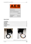
NEMIC-LAMBDA
SWS 600
INSTRUCTION MANUAL
1. Front Panel Explanation
SWS600 Panel
(1) V.ADJ : Output voltage adjustment trimmer
(The output voltage rises when trimmer is
turned clockwise.)
(2) ON : Output (Power On) indication LED
(The indicator turns on when the power supply
output is in normal operating condition.)
(3) + : + Output terminal (M4 screw x 3)
(4) - : - Output terminal (M4 screw x 3)
(5) +S : Remote sensing terminal for + output
(for remote sensing function which compensates for line drop between power supply terminals and load terminals.)
(6) -S : Remote sensing terminal for - output
(for remote sensing function which compensates for line drop between power supply terminals and load terminals.)
(7) PC : Current balance terminal
(for current balancing in parallel operation.)
(8) TOG : Ground for CNT and PF signal
(9) CNT : ON/OFF control terminal
(for power supply output on and off control
with an external signal.)
(10) PF : Power fail signal output terminal.
(As the output voltage drops, “Power Fail”
terminal will output “High”.)
(11)
: Safety Earth (Frame ground)
(12) AC input terminal N : Neutral line
(13) AC input terminal L : Live Line (Fuse in line)
1
NEMIC-LAMBDA
SWS 600
INSTRUCTION MANUAL
2. Terminal Connection Method
l Remote sensing lines shall be twisted or use
shielded wire.
l Remote ON/OFF control lines shall be twisted
or use shielded wire.
l Output current of each terminal pin must be less
than 40A.
l Input must be off when making connection.
l Connect terminal to ground terminal of the
equipment.
l The output load line and input line shall be separated and twisted to improve noise sensitivity.
SWS600 Panel Side
n Basic connection (Local sensing)
n Remote sensing required
Connect “+S” terminal to “+” terminal and “-S”
terminal to “-” terminal with short piece.
(Mounted on terminal strip at time of shipment.)
Remove the two short pieces between “+/-S” to
“+/-” terminals from terminal strip. Connect “+S”
terminal to “+” terminal of load and “-S” terminal to
“-” output terminal of load with wires. When remote
sensing terminal are opened, output is shut down.
n ON/OFF control required
n PF signal output required
Use the circuit shown below.
“TOG” terminal is Ground for CNT.
Open collector method shown below shall be used.
“TOG” terminal is ground for “PF” terminal.
2
NEMIC-LAMBDA
SWS 600
INSTRUCTION MANUAL
3. Functions and Precautions
3-1. Input Voltage Range
automatically recovered when the overload condition is cancelled. Do not operate overload or dead
short conditions for more than 30 seconds, which
could result in damage or insulation failure.
Input voltage range is single phase 85~265VAC
(47~63Hz) or 120~330VDC. Input voltage which is
out of specification may cause unit damage. For
cases where conformance to various safety specs
(UL,CSA,EN) are required, input voltage range will
be 100 ~ 240VAC ( 50/60Hz ).
Maximum output power is derated linearly if input
voltage is less than 115Vac.
3-5. Over Temperature Protection (OTP)
Over temperature protection function is provided.
When ambient or internal temperature rises abnormally, OTP will shut down the output. After shut
down, first remove the input and cool it down before re-input.
Output derating vs Input voltage.
3-6. Low Output Detection Circuit
Low output detection circuit is provided. PF signal
will turn “High” level to indicate the abnormal status when the output voltage is below 80% of rated
value caused by either the drop or brown out of the
input voltage or OCP, OVP and OTP function operation.
The PF signal is insulated by a photo coupler. It
uses the open collector method shown as below.
SWS600-24, 48V
SWS600-5V
3-2. Output Voltage Range
V.ADJ trimmer on the front panel is for output voltage adjustment within the range of specifications.
To turn the trimmer clockwise, the output voltage
will be increased. Note over voltage protection
(OVP) function may trigger if the output voltage is
increased excessively.
PF
VCE max=30V
IC max=20mA
TOG
3-3. Over Voltage Protection (OVP)
3-7. Remote Sensing (+S, -S terminal)
The OVP function (Inverter shut down method,
manual reset type) is provided. When OVP triggers,
the output will be shut down. The input shall be removed for a few minutes, and then re-input for recovery of the output. OVP setting is fixed and not to
be adjusted externally.
This function compensates voltage drop of wiring
from output terminals to load terminals. Connect
“+S” terminal to “+” terminal of load and “-S” terminal to “-” terminal of load with sensing wires.
The total line voltage drop (+ side line and - side
line) shall be less than 0.3V. In case that sensing
line is too long, it is necessary to put an electrolytic
capacitor in following 3 places.
1) Across the load terminal,
2) Between “+S” terminal and “+” terminal,
3) Between “-S” terminal and “-” terminal.
3-4. Over Current Protection (OCP)
Constant current limiting, automatic recovery. OCP
function operates when the output current exceeds
OCP specifications. The output will be
3
NEMIC-LAMBDA
SWS 600
INSTRUCTION MANUAL
3-9. Output Ripple & Noise
If remote sensing terminals are opened, the output
will rise and OVP be triggered.
Ripple & noise are measured at 20MHz by using a
12’’twisted pair terminated with a 0.1uF& 47uF capacitor. When Load lines are longer, ripple becomes
larger. In this case, electrolytic capacitor, film capacitor, etc. might be necessary to use across the
load terminal. The output ripple cannot be measured
accurately if the probe ground lead of oscilloscope
is too long.
+S
+
+
+
Power
Supply
+
-S
Load
-
3-10. Parallel Operation
+
Current balancing function is provided. Either of
operations mode (A) or (B) is possible. To attach
PC to PC terminal and -S to -S terminal, the current
balancing function activates and output current of
each power supply is equivalently supplied to load.
Wires to PC terminals shall be as short as possible
and same length.
3-8. Remote ON/OFF Control
Remote ON/OFF control is available.
Using this function, output on/off is allowed to
control without input voltage on/off. It is controlled
by the voltage applied to CNT and TOG. This circuit is in the secondary (output) side of the power
supply unit. Do not connect in the primary (input)
side. And this circuit is isolated from the output by a
photo-coupler.
Power
Supply
(A) To Increase the Output Current
1.
2.
Relay, Transistor,
TTL etc.
CNT
3.
1kΩ
TB51
R
E
4.
TOG
Adjust the output voltage of each power
supply to be same value within 1% or
100mV, whichever smaller.
Use same length and type of wires for all
load lines.
Please use with output current less than
80% of rated output current for all paralleled power supply units.
Parallel operation possible until 5 units.
All paralleled units shall be same type of
power supply.
Control mode is shown below.
Power Supply
CNT Level
for TOG Terminal
Lower than 0.8V
ON
Higher than 4.5V
OFF
External Voltage Level :E
+S
Output
Condition
Load
External
Resistor :R
4.5~12.5VDC
Not required
12.5~24.5VDC
1.5k Ω
PC
-S
PC
+S
-S
4
NEMIC-LAMBDA
SWS 600
INSTRUCTION MANUAL
3-12. Remote Programming
(B) To Use as a Backup Power Supply
1. Adjust the output voltage of each power
Connecting a remote programming resistor such as
a potentiometer between “+S” and “+” terminal,
remote programming becomes possible to use. The
rate of the change due to the remote programming
resistor is 1.25V/kΩ. Please refer to customer specifications for output range.
supply to be same value.
Set power supply output voltage higher by
the forward voltage drop of diode.
Use within the specifications for output
voltage and output current.
2.
3.
Power Supply
+S
+S
+
+
-S
-
V.ADJ
AC
Vo+Vf Vo
SWS
AC
Output Power(W)=(Vo+Vf)×Io
Vf
Io
Load
Set at lowest setting
Load
3-13. Peak Output Current
-S
Vf
For SWS600-5V, the relation between peak output
current and average output current is defined as below:
+S
Vo+Vf
Ip
-S
Im
3-11. Series Operation
0A
For series operation, either method (A) or (B) is
possible.
Method (A)
τ
T
Iavg =Ip x D + Im x (1-D)
Where:
Ip = Peak output current
Im = Minimum output current
D = Duty cycle, τ/T
τ = Peak output current operating time
T = Period
Iavg = Average output current
Power
Supply
+S
Output
Terminal
-S
Load
+S
Output
Terminal
Peak output current operation should satisfy the
conditions below:
1) Duty cycle of the peak output current should be <
35%, and operating time of peak output current is
less than 5 seconds.
-S
Method (B)
Power
Supply
+S
Output
Terminal
2) Peak output current should not exceed the rated
peak current of the specifications with derating of
input voltage, input voltage derating factor for peak
output current is same as that of maximum output
current.
Load
-S
+S
Output
Terminal
Load
-S
5
NEMIC-LAMBDA
SWS 600
INSTRUCTION MANUAL
4-2. Withstand Voltage
3) Maximum allowable average output current
should be less than maximum output current of
specifications with derating of input voltage,
mounting and ambient temperature.
(Refer to section 5: Mounting direction)
This series is designed to withstand 3.0kVAC between input and output, 2.0kVAC between input
and FG (chassis), 500VAC between output and FG
(chassis), and 100VAC between output and control
terminal each for 1 minute. When testing withstand
voltage, set current limit of withstand voltage test
equipment at 20mA (Output-FG (chassis) and Output-Control : 100mA). The applied voltage must be
gradually increased from zero to testing value and
then gradually decreased for shut down. When
timer is used, the power supply may be damaged by
high impulse voltage at timer switch on and off.
Connect input and output as follows.
For example:
At 85Vac, standard mounting and 60oC ambient.
Peak output current should be less than 108A.
(120A with 90% of input voltage derating)
Average output current should be less than 63A
(100A with 90% of input voltage, 70% of ambient
and mounting derating)
4. Isolation/Withstand Voltage
Input ~ FG (chassis) (solid line)
2kVAC 1min. (20mA)
Input ~ Output (dotted line)
3kVAC 1min. (20mA)
4-1. Isolation Test
Isolation resistance between output and FG (chassis) shall be more than 100MΩ at 500VDC and
between output and control shall be more than
10MΩ at 100VDC. For safety operation, voltage
setting of DC isolation tester must be done before
the test. Ensure that it is fully discharged after the
test.
Output ~ FG (chassis)
500VDC 100MΩ or more
AC(L)
AC(L)
+
AC(N)
FG
CNT
PF
PC
FG
PC
TOG
Withstand
Voltage
Tester
-S
Isolation
Tester
-S
+S
+
-
AC(N)
+S
TOG
CNT
PF
Output ~ FG (chassis)
500VAC 1min. (100mA)
Output ~ Control
100VDC 10MΩ or more
AC(L)
AC(N)
AC(L)
+S
+
AC(N)
+S
+
-S
-S
Isolation
Tester
FG
Withstand
Voltage
Tester
FG
TOG
CNT
PF
PC
TOG
CNT
PF
6
NEMIC-LAMBDA
SWS 600
INSTRUCTION MANUAL
Output ~ Control
100VAC 1min. (100mA)
+S
AC(L)
LOAD(%)
+
AC(N)
FG
-
Ta(°C)
A
B
C
D
-S
-10 ~ +40
100
100
100
100
PC
50
100
100
100
70
55
85
85
85
55
65
55
55
55
-
TOG
Withstand
Voltage
Tester
CNT
PF
For Vin=85~115Vac, refer to section 3-1 for Input
Voltage Derating factor.
5. Mounting Directions
For example:
At Vin=85Vac:
5-1. Output Derating according to the Mounting Directions
Recommended standard mounting method is (A).
Method (B), (C) and (D) are also possible. Refer to
the derating below.
(A)Standard
(B)
(C)
Output current derating (%)
Ta (°C)
Mounting
5V
24, 48V
A,B,C
D
A,B,C
D
-10 ~ +40
90
90
80
80
50
90
63
80
56
55
76.5
49.5
68
44
65
49.5
-
44
-
5-2. Mounting Method
More than 50mm
(D)
(E)Inhibit
More than
Side 30mm
More than 50mm
Back side
(F)Inhibit
Fan
Top (SWS600)
Air flow
Front Side
(Example: Mounting C)
Output Derating Curve
(Vin: 115~265VAC)
(1) Forced air cooling type power supply. This
power supply has ventilating holes on the front,
back, and side panels. Keep these three areas
freely as much as possible.
(2) The maximum allowable penetration of
mounting screw is 6mm.
(3) Recommended torque for mounting screws:
M4 screw: 1.27 N⋅m ( 13.0 kgf⋅cm )
7
NEMIC-LAMBDA
SWS 600
INSTRUCTION MANUAL
the FG terminal of SWS series to earth terminal
of equipment system where power supply unit
is mounted on.
6. Wiring Method
l
The output load line and input line shall be
separated and twisted to improve noise sensitivity.
l The sensing lines shall be twisted and separated
from the output lines.
l Use all lines as thick and short as possible to
make lower impedance.
l Noise can be eliminated by attaching a capacitor to the load terminals.
l The output current of each output terminal is
limited to 40A . When it is more than 40A,
use 2 or 3terminals.
l For safety and EMI considerations, connect
terminal to the mounting set ground terminal.
l Recommended torque for the terminal pieces:
Output terminal (M4 screw):
1.27 N⋅m ( 13.0 kgf⋅cm )
Input and signal terminal (M3.5 screw):
0.74 N⋅m( 7.5 kgf⋅cm )
8. External Fuse Rating
Refer to the following fuse rating when selecting
the external fuses that are to be used on input line.
Surge current flows when line turns on. Use slowblow fuse or time-lag fuse. Do not use fast-blow
fuse. Fuse rating is specified by in-rush current value at line turn-on. Do not select the fuse according
to input current (rms.) values under the actual load
condition.
SWS600 : 15A
9. Fan life expectancy
The Fan-life has limitation. Therefore, periodic
maintenance by exchanging the life-expired fan is
required. The following figure shows the life of fan.
10
Life expectancy (years)
7. EMC
This power supply is primarily designed and manufactured to be used and enclosed in other equipment.
The installation, wiring, grounding and end application of the switching power supply in the equipment system may influence its EMC characteristics.
Therefore, the EMC performance has to be tested on
end system level. Additional filtering may be required depends on application and installation
methods. Please refer to following application notes
which may help to improve EMC performance.
1
0
50
70
Fan exhaust temperature (oC)
Measuring point
l The output load line and input line shall be
separated and twisted to reduce noise.
l Use all lines as thick and short as possible to
make lower impedance.
l Noise can be eliminated by attaching a
capacitor to the load terminals and between
output terminals to earth (frame ground).
l Use of metal enclosure on system design.
For safety and EMI considerations, connect
Air flow
P.S.
50mm
Measuring point of fan exhaust temperature.
8
100
NEMIC-LAMBDA
SWS 600
INSTRUCTION MANUAL
10. Before concluding that the unit is
at fault…
Before concluding that the unit is at fault, make the
following checks.
l Check if the rated input voltage is connected.
l Check if the wiring of input and output is correct.
l Check if the wire material is not too thin.
l Check if the output voltage control (V.ADJ) is
properly adjusted.
l If use function of the Remote ON/OFF control,
Check if the Remote ON/OFF control connector is not opened.
l Check if the output current and output wattage
does not over specification.
l Audible noise can be heard during DynamicLoad operation.
l Audible noise can be heard when input voltage
waveform is not sinusoidal wave.
11. Notes
1.
2.
Over-voltage Category II
Radio Interference Suppression Test is not
performed.
9