1
I
7
Motion Control via EtherCAT
Introduction to EtherCAT
0
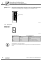
7.1.2
Position mode
[1]
Xref
vref
Xact
vact
[A]
[3]
[2]
[4]
tref
M
V
[5]
X
[5]
[6]
X
[C]
[B]
61479AXX
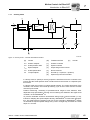
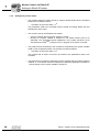
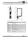
Figure 18: Position mode – cascade with bus interface
[A]
Control
[B]
Fieldbus interface
[C]
Inverter
xref
Position setpoint
[1]
Position controller
xact
Actual position value
[2]
Speed controller
vref
Speed setpoint
[3]
Output stage of the inverter
vact
Actual speed value
[4]
Driven machine
tref
Torque setpoint
[5]
Encoder (V = speed; X = position)
[6]
Optional synchronous encoder
In position mode, a position setpoint is transferred cyclically from the controller to the
inverter and the actual position value is returned by the inverter or the separate position
sensor.
In position mode, the inverter follows the changing position setpoint and generates the
required speed setpoint for the speed controller [2] itself out of the actual position xact
from [5] or [6]. The control time-slices of the controller, bus transfer, the internal processing cycles of the inverter and the encoder must be synchronized.
Once the position in the controller has been referenced to the position in the inverter,
permitted travel ranges or limit switches can be monitored in the inverter. You must
check carefully whether the settings for the load-dependent ramp specification and lag
error monitoring in the inverter are plausible.
To prevent unwanted excessive acceleration during longer control intervals (>1 ms),
instead of adopting the position setpoint directly, MOVIDRIVE® B uses linear interpolation. This means that for a setpoint cycle of 5 ms, the controller in MOVIDRIVE® B does
not activate the required position change every 5 ms in a single step, but rather in 5
small steps of 1 ms each.
62
Manual – Fieldbus Interface DFE24B EtherCAT