1
ExtremeWare XOS Concepts Guide
Software Version 11.1
Extreme Networks, Inc.
3585 Monroe Street
Santa Clara, California 95051
(888) 257-3000
(408) 579-2800
http://www.extremenetworks.com
Published: December 2004
Part number: 100170-00 Rev 01
Alpine, Altitude, BlackDiamond, EPICenter, Ethernet Everywhere, Extreme Ethernet Everywhere, Extreme
Networks, Extreme Turbodrive, Extreme Velocity, ExtremeWare, ExtremeWorks, GlobalPx Content Director, the Go
Purple Extreme Solution Partners Logo, ServiceWatch, Summit, the Summit7i Logo, and the Color Purple, among
others, are trademarks or registered trademarks of Extreme Networks, Inc. or its subsidiaries in the United States
and other countries. Other names and marks may be the property of their respective owners.
© 2004 Extreme Networks, Inc. All Rights Reserved.
Specifications are subject to change without notice.
The ExtremeWare XOS operating system is based, in part, on the Linux operating system. The machine-readable
copy of the corresponding source code is available for the cost of distribution. Please direct requests to Extreme
Networks for more information at the following address:
Software Licensing Department
3585 Monroe Street
Santa Clara CA 95051
NetWare and Novell are registered trademarks of Novell, Inc. Merit is a registered trademark of Merit Network,
Inc. Solaris and Java are trademarks of Sun Microsystems, Inc. F5, BIG/ip, and 3DNS are registered trademarks of
F5 Networks, Inc. see/IT is a trademark of F5 Networks, Inc.
sFlow® is a registered trademark of InMon Corporation.
All other registered trademarks, trademarks and service marks are property of their respective owners.
123456789
Authors: Hugh Bussell, Megan Mahar, Peggy Murphy
Production: Megan Mahar and Peggy Murphy
ExtremeWare XOS 11.1 Concepts Guide
2
Contents
Preface......................................................................................................................................... 17
Introduction .............................................................................................................................17
Terminology........................................................................................................................17
Conventions..............................................................................................................................18
Related Publications .................................................................................................................18
Using ExtremeWare XOS Publications Online .........................................................................19
Part 1: Using ExtremeWare XOS
Chapter 1: ExtremeWare XOS Overview........................................................................................... 23
Platforms and Required Software Versions ...................................................................................23
Summary of Features.................................................................................................................23
Feature Highlights of ExtremeWare XOS 11.1 ........................................................................24
Software Licensing ....................................................................................................................27
Upgrading to Core License—Aspen 8810 Switch Only ............................................................27
Advanced Core License—BlackDiamond 10K Switch Only.......................................................28
Security Licensing...............................................................................................................29
Software Factory Defaults ..........................................................................................................29
Chapter 2: Accessing the Switch.................................................................................................... 31
Understanding the Command Syntax...........................................................................................31
Syntax Helper .....................................................................................................................32
Command Shortcuts ............................................................................................................32
Modular Switch Numerical Ranges........................................................................................33
Names ...............................................................................................................................33
Symbols .............................................................................................................................33
Limits ................................................................................................................................34
Line-Editing Keys......................................................................................................................34
Command History......................................................................................................................35
Common Commands..................................................................................................................35
Configuring Management Access ................................................................................................37
User Account ......................................................................................................................37
Administrator Account .........................................................................................................38
Default Accounts.................................................................................................................38
Creating a Management Account...........................................................................................39
Failsafe Account .................................................................................................................40
Domain Name Service Client Services .........................................................................................41
Checking Basic Connectivity.......................................................................................................41
Ping...................................................................................................................................41
Traceroute ..........................................................................................................................42
ExtremeWare XOS 11.1 Concepts Guide
3
Contents
Chapter 3: Managing the Switch .................................................................................................... 43
Overview ..................................................................................................................................43
Understanding the ExtremeWare XOS Shell .................................................................................44
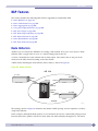
Using the Console Interface .......................................................................................................44
Using the 10/100 Ethernet Management Port ..............................................................................44
Authenticating Users .................................................................................................................45
RADIUS Client ....................................................................................................................45
TACACS+ ...........................................................................................................................45
Configuring RADIUS Client and TACACS+ .............................................................................45
Management Accounts.........................................................................................................46
Using Telnet .............................................................................................................................46
About the Telnet Client ........................................................................................................46
About the Telnet Server .......................................................................................................46
Connecting to Another Host Using Telnet...............................................................................47
Configuring Switch IP Parameters .........................................................................................47
Configuring Telnet Access to the Switch ................................................................................49
Disconnecting a Telnet Session ............................................................................................50
Using Secure Shell 2.................................................................................................................50
Using the Trivial File Transfer Protocol ........................................................................................50
Connecting to Another Host Using TFTP ................................................................................50
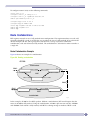
Understanding System Redundancy ............................................................................................51
Node Election .....................................................................................................................51
Replicating Data Between Nodes ..........................................................................................52
Viewing Node Status............................................................................................................54
Understanding Power Supply Management ..................................................................................55
Initial System Boot-Up ........................................................................................................55
Removing a Power Supply ....................................................................................................56
Installing or Providing Power to a Power Supply .....................................................................56
Displaying Power Supply Information ....................................................................................56
Using the Simple Network Management Protocol .........................................................................56
Enabling and Disabling SNMPv1/v2c and SNMPv3 ................................................................57
Accessing Switch Agents......................................................................................................57
Supported MIBs ..................................................................................................................58
Configuring SNMPv1/v2c Settings ........................................................................................58
Displaying SNMP Settings....................................................................................................58
SNMPv3.............................................................................................................................59
Message Processing.............................................................................................................60
SNMPv3 Security ................................................................................................................60
SNMPv3 MIB Access Control ...............................................................................................63
SNMPv3 Notification...........................................................................................................64
Using the Simple Network Time Protocol.....................................................................................66
Configuring and Using SNTP ................................................................................................67
SNTP Example....................................................................................................................70
ExtremeWare XOS 11.1 Concepts Guide
4
Contents
Chapter 4: Managing the ExtremeWare XOS Software...................................................................... 71
Overview of the ExtremeWare XOS Software .................................................................................71
Understanding the ExtremeWare XOS Software ......................................................................71
Using the ExtremeWare XOS File System.....................................................................................72
Moving or Renaming Files on the Switch ...............................................................................72
Copying Files on the Switch .................................................................................................73
Displaying Files on the Switch ..............................................................................................74
Deleting Files From the Switch .............................................................................................74
Managing the Configuration File .................................................................................................75
Managing ExtremeWare XOS Processes .......................................................................................75
Displaying Process Information.............................................................................................76
Stopping a Process..............................................................................................................76
Starting a Process ...............................................................................................................76
Understanding Memory Protection ..............................................................................................77
Chapter 5: Configuring Slots and Ports on a Switch......................................................................... 79
Configuring a Slot on a Modular Switch .......................................................................................79
I/O Ports on Aspen 8810 MSM Module .................................................................................80
Configuring Ports on a Switch.....................................................................................................80
Enabling and Disabling Switch Ports .....................................................................................81
Configuring Switch Port Speed and Duplex Setting .................................................................81
Jumbo Frames ..........................................................................................................................83
Jumbo Frames on the Aspen 8810 Switch Only .....................................................................84
Enabling Jumbo Frames.......................................................................................................84
Path MTU Discovery ............................................................................................................84
IP Fragmentation with Jumbo Frames....................................................................................85
IP Fragmentation within a VLAN ...........................................................................................86
Load Sharing on the Switch .......................................................................................................86
Load-Sharing Algorithms......................................................................................................87
Configuring Switch Load Sharing ..........................................................................................89
Load-Sharing Examples .......................................................................................................90
Displaying Switch Load Sharing............................................................................................90
Switch Port Mirroring.................................................................................................................91
Switch Port Mirroring on the Aspen 8810 Switch Only ............................................................91
Switch Port Mirroring on the BlackDiamond 10K Switch Only..................................................92
Switch Port-Mirroring Rules and Restrictions for All Switches ..................................................92
Switch Port-Mirroring Examples ............................................................................................93
Verifying the Switch Port-Mirroring Configuration ...................................................................93
Extreme Discovery Protocol ........................................................................................................94
Software-Controlled Redundant Port and Smart Redundancy .........................................................96
Guidelines for Software-Controlled Redundant Ports and Port Groups .......................................97
Configuring Software-Controlled Redundant Ports...................................................................97
Verifying Software-Controlled Redundant Port Configurations...................................................98
Displaying Port Configuration Information....................................................................................99
Chapter 6: Power Over Ethernet.................................................................................................... 103
Summary of PoE Features ........................................................................................................103
Power Checking for PoE Module ...............................................................................................103
Power Delivery ........................................................................................................................104
ExtremeWare XOS 11.1 Concepts Guide
5
Contents
Enabling PoE to the Switch ................................................................................................104
Power Reserve Budget Per Slot...........................................................................................104
PD Disconnect Precedence ................................................................................................105
Port Disconnect or Fault ....................................................................................................106
Port Power Reset...............................................................................................................107
PoE Usage Threshold.........................................................................................................107
Legacy Devices .................................................................................................................107
PoE Operator Limits ..........................................................................................................108
LEDs......................................................................................................................................108
Configuring PoE ......................................................................................................................108
Enabling Inline Power........................................................................................................109
Reserving Power for a Slot..................................................................................................109
Setting the Disconnect Precedence .....................................................................................110
Configuring the Usage Threshold ........................................................................................111
Configuring the Switch to Detect Legacy PDs .......................................................................112
Configuring the Operator Limit ...........................................................................................112
Configuring PoE Port Labels ...............................................................................................113
Power Cycling Connected PDs ............................................................................................113
Displaying PoE Settings and Statistics ......................................................................................113
Clearing Statistics .............................................................................................................113
Displaying System Power Information..................................................................................113
Displaying Slot PoE Information .........................................................................................116
Displaying Port PoE Information .........................................................................................117
Chapter 7: Status Monitoring and Statistics .................................................................................. 121
Status Monitoring....................................................................................................................121
Viewing Port Statistics .............................................................................................................121
Viewing Port Errors ..................................................................................................................122
Using the Port Monitoring Display Keys .....................................................................................123
Slot Diagnostics ......................................................................................................................123
Running Diagnostics on I/O and Management Modules .........................................................124
Observing LED Behavior During a Diagnostic Test.................................................................124
Displaying Diagnostic Test Results......................................................................................126
System Health Checking ..........................................................................................................126
Understanding the System Health Checker—BlackDiamond 10K Switch Only .........................126
Understanding the System Health Checker—Aspen 8810
Switch Only ......................................................................................................................127
Enabling and Disabling Backplane Diagnostic Packets on the Switch .....................................128
Configuring Backplane Diagnostic Packets on the Switch ......................................................128
System Health Check Examples..........................................................................................128
Setting the System Recovery Level............................................................................................130
Viewing the System Temperature ..............................................................................................130
Event Management System/Logging ..........................................................................................131
Sending Event Messages to Log Targets...............................................................................132
Filtering Events Sent to Targets ..........................................................................................133
Displaying Real-Time Log Messages ....................................................................................141
Displaying Event Logs........................................................................................................141
Uploading Event Logs ........................................................................................................141
Displaying Counts of Event Occurrences ..............................................................................142
Displaying Debug Information.............................................................................................143
Logging Configuration Changes...........................................................................................143
ExtremeWare XOS 11.1 Concepts Guide
6
Contents
Using sFlow............................................................................................................................143
Configuring sFlow..............................................................................................................144
Displaying sFlow Information..............................................................................................146
RMON....................................................................................................................................147
About RMON ....................................................................................................................147
Supported RMON Groups of the Switch ...............................................................................148
Configuring RMON ............................................................................................................149
Event Actions ...................................................................................................................150
Displaying RMON Information ............................................................................................150
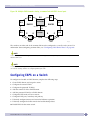
Chapter 8: Virtual LANs ............................................................................................................... 151
Overview of Virtual LANs..........................................................................................................151
Benefits ...........................................................................................................................151
Virtual Routers and VLANs—BlackDiamond 10K Switch Only................................................152
Types of VLANs.......................................................................................................................152
Port-Based VLANs .............................................................................................................152
Tagged VLANs ..................................................................................................................155
Protocol-Based VLANs .......................................................................................................157
Precedence of Tagged Packets Over Protocol Filters .............................................................159
VLAN Names ..........................................................................................................................159
Default VLAN....................................................................................................................160
Renaming a VLAN .............................................................................................................160
Configuring VLANs on the Switch .............................................................................................160
VLAN Configuration Examples ............................................................................................161
Displaying VLAN Settings.........................................................................................................162
Displaying Protocol Information ..........................................................................................163
Tunneling (VMANs) .................................................................................................................163
Guidelines for Configuring VMANs ......................................................................................164
Configuring VMANs ...........................................................................................................165
Displaying VMAN Configurations.........................................................................................167
Chapter 9: Virtual Routers............................................................................................................ 169
Virtual Routers Overview ..........................................................................................................169
Types of Virtual Routers .....................................................................................................169
Virtual Router Configuration Domain—BlackDiamond 10K Switch Only ..................................171
Using Virtual Routers—BlackDiamond 10K Switch Only .............................................................171
Creating Virtual Routers .....................................................................................................172
Adding Ports to a Virtual Router..........................................................................................172
Adding Routing Protocols to a Virtual Router........................................................................172
Displaying Ports and Protocols............................................................................................173
Configuring the Routing Protocols and VLANs ......................................................................173
Virtual Router Configuration Example ........................................................................................174
Chapter 10: Forwarding Database................................................................................................. 175
Overview of the FDB ................................................................................................................175
FDB Contents ...................................................................................................................175
How FDB Entries Get Added...............................................................................................175
FDB Entry Types ...............................................................................................................176
Disabling MAC Address Learning ........................................................................................177
ExtremeWare XOS 11.1 Concepts Guide
7
Contents
FDB Configuration Examples ....................................................................................................177
Configuring the FDB Aging Time...............................................................................................177
MAC-Based Security................................................................................................................178
Displaying FDB Entries ............................................................................................................178
Chapter 11: Policies and ACLs ..................................................................................................... 179
Policy Manager .......................................................................................................................179
Creating and Editing Policies....................................................................................................179
Using the Edit Command ...................................................................................................180
Using a Separate Machine .................................................................................................180
Checking Policies ..............................................................................................................180
Refreshing Policies............................................................................................................181
Applying Policies ....................................................................................................................181
Applying ACL Policies........................................................................................................181
Applying Routing Policies ..................................................................................................182
ACL Policies ...........................................................................................................................182
ACL Policy File Syntax .......................................................................................................183
ACL Evaluation Precedence................................................................................................187
ACL Metering—Aspen 8810 Only .......................................................................................188
Example ACL Rule Entries .................................................................................................189
Displaying and Clearing ACL Counters .................................................................................190
Routing Policies......................................................................................................................190
Routing Policy File Syntax..................................................................................................191
Policy Examples ................................................................................................................195
Chapter 12: Quality of Service ..................................................................................................... 201
Overview of Policy-Based Quality of Service ...............................................................................201
Applications and Types of QoS .................................................................................................202
Voice Applications.............................................................................................................202
Video Applications.............................................................................................................202
Critical Database Applications ............................................................................................203
Web Browsing Applications ................................................................................................203
File Server Applications .....................................................................................................203
Configuring QoS......................................................................................................................204
Configuring QoS on the Aspen 8810 Switch Only .................................................................204
QoS Profiles ...........................................................................................................................205
QoS Profiles on the Aspen 8810 Switch Only.......................................................................205
QoS Profiles on the BlackDiamond 10K Switch ....................................................................206
Traffic Groupings ....................................................................................................................207
ACL-Based Traffic Groupings..............................................................................................208
Explicit Class of Service (802.1p and DiffServ) Traffic Groupings ..........................................208
Physical and Logical Groupings ..........................................................................................215
Verifying QoS Configuration and Performance ............................................................................219
Monitoring Performance—BlackDiamond 10K Switch Only ...................................................219
Displaying QoS Profile Information......................................................................................219
Guidelines for Configuring QoS .................................................................................................220
ExtremeWare XOS 11.1 Concepts Guide
8
Contents
Egress Traffic Rate Limiting—Aspen 8810 Switch Only ..............................................................220
Bi-Directional Rate Shaping—BlackDiamond 10K Switch Only....................................................221
Bandwidth Settings ...........................................................................................................222
Configuring Bi-Directional Rate Shaping..............................................................................223
Chapter 13: Security ................................................................................................................... 225
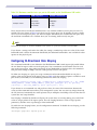
Security Overview....................................................................................................................225
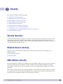
Network Access Security ..........................................................................................................225
MAC Address Security .............................................................................................................225
Limiting Dynamic MAC Addresses.......................................................................................226
MAC Address Lock Down ...................................................................................................227
Network Login ........................................................................................................................228
Web-Based, MAC-based, and 802.1x Authentication ............................................................228
Campus and ISP Modes .....................................................................................................230
Interoperability Requirements.............................................................................................231
Multiple Supplicant Support ..............................................................................................232
Exclusions and Limitations.................................................................................................233
Configuring Network Login .................................................................................................233
Web-Based Authentication User Login Using Campus Mode ..................................................235
Displaying Network Login Settings ......................................................................................236
Disabling Network Login ....................................................................................................236
Additional Configuration Details..........................................................................................236
MAC-Based Authentication.................................................................................................237
DHCP Server ..........................................................................................................................238
DHCP Server on the Switch ................................................................................................238
Displaying DHCP Information .............................................................................................239
Denial of Service Protection .....................................................................................................239
Configuring Denial of Service Protection ..............................................................................240
Management Access Security ...................................................................................................241
Authenticating Users Using RADIUS or TACACS+ ......................................................................241
RADIUS ...........................................................................................................................242
Configuring RADIUS ..........................................................................................................243
TACACS+ .........................................................................................................................248
Secure Shell 2 ........................................................................................................................249
Enabling SSH2 for Inbound Switch Access ..........................................................................249
Using SCP2 from an External SSH2 Client ..........................................................................250
Chapter 14: CLEARFlow ............................................................................................................... 253
Overview ................................................................................................................................253
Configuring CLEARFlow ...........................................................................................................253
Displaying CLEARFlow Configuration and Activity.................................................................254
Adding CLEARFlow Rules to ACLs ............................................................................................254
CLEARFlow Rule Types......................................................................................................255
CLEARFlow Rule Actions ...................................................................................................259
CLEARFlow Rule Examples ......................................................................................................261
Count Rule Type Example ..................................................................................................261
Delta Rule Type Example ...................................................................................................262
Ratio Rule Type Example ...................................................................................................263
Delta-Ratio Rule Type Example...........................................................................................264
ExtremeWare XOS 11.1 Concepts Guide
9
Contents
Part 2: Using Switching and Routing Protocols
Chapter 15: Ethernet Automatic Protection Switching.................................................................... 267
Licensing ...............................................................................................................................267
Overview of the EAPS Protocol .................................................................................................267
Fast Convergence ..............................................................................................................269
Fault Detection and Recovery ...................................................................................................269
Link Down Message Sent by a Transit Node .........................................................................270
Ring Port Down Event Sent by Hardware Layer .....................................................................270
Polling .............................................................................................................................271
Restoration Operations.......................................................................................................271
Multiple EAPS Domains...........................................................................................................272
EAPS Data VLAN Spanning Two Rings Connected by One Switch...........................................272
Multiple EAPS Domains per Ring—Spatial Reuse.................................................................273
Multiple EAPS Rings Sharing a Common Link ......................................................................273
Configuring EAPS on a Switch ..................................................................................................274
Creating and Deleting an EAPS Domain...............................................................................275
Defining the EAPS Mode of the Switch................................................................................275
Configuring EAPS Polling Timers ........................................................................................276
Configuring the Primary and Secondary Ports .......................................................................277
Configuring the EAPS Control VLAN ....................................................................................277
Configuring the EAPS Protected VLANs ...............................................................................278
Enabling and Disabling Fast Convergence ............................................................................278
Enabling and Disabling an EAPS Domain.............................................................................278
Enabling and Disabling EAPS on the Switch ........................................................................278
Unconfiguring an EAPS Ring Port .......................................................................................279
Displaying EAPS Status Information....................................................................................279
Configuring EAPS Shared Ports ................................................................................................282
Steady State .....................................................................................................................283
Common Link Failures .......................................................................................................284
Flushing the FDBs.............................................................................................................284
Creating and Deleting a Shared Port....................................................................................285
Defining the Mode of the Shared Port..................................................................................285
Configuring the Link ID of the Shared Port...........................................................................285
Configuring the Shared Port Segment Timer.........................................................................285
Unconfiguring an EAPS Shared Port....................................................................................286
Displaying EAPS Shared-Port Status Information..................................................................286
EAPS Shared Port Configuration Rules ......................................................................................289
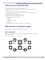
EAPS Shared Port Configuration Examples ................................................................................289
Basic Configuration ...........................................................................................................289
Basic Core Configuration....................................................................................................290
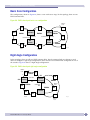
Right Angle Configuration ..................................................................................................290
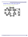
Combined Basic Core and Right Angle Configuration ............................................................291
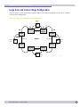
Large Core and Access Rings Configuration..........................................................................292
Advanced Configuration .....................................................................................................293
Chapter 16: Spanning Tree Protocol............................................................................................. 295
Overview of the Spanning Tree Protocol.....................................................................................295
Spanning Tree Domains ...........................................................................................................295
Member VLANs .................................................................................................................296
STPD Modes.....................................................................................................................297
ExtremeWare XOS 11.1 Concepts Guide
10
Contents
Encapsulation Modes.........................................................................................................297
STP States .......................................................................................................................298
Binding Ports....................................................................................................................299
Rapid Root Failover ...........................................................................................................301
STP and Hitless Failover—BlackDiamond 10K Switch Only...................................................301
STP Configurations..................................................................................................................302
Basic STP Configuration ....................................................................................................302
Multiple STPDs on a Port ...................................................................................................305
VLAN Spanning Multiple STPDs .........................................................................................305
EMISTP Deployment Constraints ........................................................................................306
Per VLAN Spanning Tree..........................................................................................................308
STPD VLAN Mapping.........................................................................................................308
Native VLAN .....................................................................................................................308
Rapid Spanning Tree Protocol ..................................................................................................308
RSTP Concepts .................................................................................................................309
RSTP Operation ................................................................................................................311
STP Rules and Restrictions ......................................................................................................318
Configuring STP on the Switch .................................................................................................319
STP Configuration Examples ....................................................................................................320
Basic 802.1D Configuration Example..................................................................................320
EMISTP Configuration Example ..........................................................................................321
RSTP 802.1w Configuration Example..................................................................................322
Displaying STP Settings...........................................................................................................323
Chapter 17: Extreme Standby Router Protocol ............................................................................... 325
Overview of ESRP ...................................................................................................................325
ESRP Modes of Operation ..................................................................................................325
ESRP and ELRP................................................................................................................326
Reasons to Use ESRP ........................................................................................................326
ESRP Concepts.......................................................................................................................326
ESRP-Aware Switches .......................................................................................................328
Standard and Extended ESRP ............................................................................................329
ESRP Domains .................................................................................................................330
Linking ESRP Switches......................................................................................................331
ESRP and Hitless Failover—BlackDiamond 10K Switch Only ................................................331
Determining the ESRP Master ..................................................................................................332
Master Switch Behavior .....................................................................................................332
Pre-Master Switch Behavior................................................................................................333
Slave Switch Behavior .......................................................................................................333
Neutral Switch Behavior ....................................................................................................333
Electing the Master Switch.................................................................................................333
ESRP Failover Time...........................................................................................................334
ESRP Election Algorithms ..................................................................................................334
Configuring an ESRP Domain on a Switch .................................................................................336
Creating and Deleting an ESRP Domain...............................................................................336
Configuring the ESRP Domain ID........................................................................................337
Adding VLANs to an ESRP Domain .....................................................................................337
Enabling and Disabling an ESRP Domain ............................................................................338
ExtremeWare XOS 11.1 Concepts Guide
11
Contents
Advanced ESRP Features.........................................................................................................339
ESRP Tracking..................................................................................................................339
ESRP Port Restart .............................................................................................................342
ESRP Host Attach .............................................................................................................342
ESRP Port Weight and Don’t Count .....................................................................................343
ESRP Groups ....................................................................................................................344
Displaying ESRP Information ...................................................................................................345
Using ELRP with ESRP............................................................................................................345
Using ELRP with ESRP to Recover Loops ............................................................................346
Configuring ELRP..............................................................................................................346
Displaying ELRP Information..............................................................................................347
ESRP Examples ......................................................................................................................348
Single Domain Using Layer 2 and Layer 3 Redundancy.........................................................348
Multiple Domains Using Layer 2 and Layer 3 Redundancy ....................................................351
ESRP Cautions .......................................................................................................................353
Configuring ESRP and IP Multinetting.................................................................................353
ESRP and STP..................................................................................................................353
ESRP and VRRP ...............................................................................................................353
ESRP Groups and Host Attach............................................................................................353
Port Configurations and ESRP ............................................................................................353
Chapter 18: Virtual Router Redundancy Protocol........................................................................... 355
Overview ................................................................................................................................355
Determining the VRRP Master ..................................................................................................355
VRRP Tracking..................................................................................................................356
Electing the Master Router.................................................................................................358
Additional VRRP Highlights......................................................................................................358
VRRP Operation ......................................................................................................................359
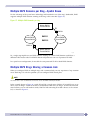
Simple VRRP Network Configuration ...................................................................................359
Fully Redundant VRRP Network..........................................................................................360
VRRP Configuration Parameters................................................................................................361
VRRP Examples ......................................................................................................................362
Configuring the Simple VRRP Network ................................................................................362
Configuring the Fully Redundant VRRP Network...................................................................363
VRRP Cautions .......................................................................................................................364
Assigning Multiple Virtual IP Addresses...............................................................................364
VRRP and ESRP ...............................................................................................................364
Chapter 19: IP Unicast Routing .................................................................................................... 365
Overview of IP Unicast Routing.................................................................................................365
Router Interfaces ..............................................................................................................365
Populating the Routing Table .............................................................................................366
Proxy ARP ..............................................................................................................................368
ARP-Incapable Devices ......................................................................................................368
Proxy ARP Between Subnets ..............................................................................................369
Relative Route Priorities ..........................................................................................................369
Configuring IP Unicast Routing ................................................................................................370
Verifying the IP Unicast Routing Configuration...........................................................................370
Routing Configuration Example.................................................................................................370
ExtremeWare XOS 11.1 Concepts Guide
12
Contents
IP Multinetting .......................................................................................................................372
Multinetting Topology ........................................................................................................372
How Multinetting Affects Other Features .............................................................................373
Configuring IP Multinetting ................................................................................................377
IP Multinetting Examples ...................................................................................................377
Configuring DHCP/BOOTP Relay ...............................................................................................378
Configuring the DHCP Relay Agent Option (Option 82) .........................................................378
Verifying the DHCP/BOOTP Relay Configuration ...................................................................379
UDP Echo Server ..............................................................................................................380
Chapter 20: Interior Gateway Protocols ........................................................................................ 381
Overview ................................................................................................................................381
RIP Versus OSPF ..............................................................................................................382
Advantages of RIP and OSPF..............................................................................................382
Overview of RIP ......................................................................................................................382
Routing Table ...................................................................................................................382
Split Horizon ....................................................................................................................383
Poison Reverse .................................................................................................................383
Triggered Updates .............................................................................................................383
Route Advertisement of VLANs ...........................................................................................383
RIP Version 1 Versus RIP Version 2 ....................................................................................383
Overview of OSPF....................................................................................................................384
Licensing .........................................................................................................................384
OSPF Edge Mode ..............................................................................................................384
Link State Database ..........................................................................................................384
Areas ...............................................................................................................................386
Point-to-Point Support .......................................................................................................389
Route Redistribution ...............................................................................................................389
Configuring Route Redistribution ........................................................................................390
OSPF Timers and Authentication ........................................................................................391
RIP Configuration Example ......................................................................................................391
Configuring OSPF....................................................................................................................393
Configuring OSPF Wait Interval...........................................................................................393
OSPF Wait Interval Parameters ...........................................................................................393
OSPF Configuration Example....................................................................................................394
Configuration for ABR1......................................................................................................395
Configuration for IR1 .........................................................................................................396
Displaying OSPF Settings.........................................................................................................396
Chapter 21: Exterior Gateway Routing Protocols............................................................................ 397
Licensing ...............................................................................................................................397
Overview ................................................................................................................................398
BGP Attributes........................................................................................................................398
BGP Communities ...................................................................................................................398
BGP Features .........................................................................................................................399
Route Reflectors ...............................................................................................................399
Route Confederations ........................................................................................................401
Route Aggregation .............................................................................................................404
Using the Loopback Interface .............................................................................................404
BGP Peer Groups ..............................................................................................................404
ExtremeWare XOS 11.1 Concepts Guide
13
Contents
BGP Route Flap Dampening ...............................................................................................405
BGP Route Selection .........................................................................................................407
Stripping Out Private AS Numbers from Route Updates ........................................................407
Route Redistribution .........................................................................................................408
BGP Static Network...........................................................................................................408
Chapter 22: IP Multicast Routing.................................................................................................. 409
Overview ................................................................................................................................409
PIM Overview....................................................................................................................409
IGMP Overview .................................................................................................................411
Configuring IP Multicasting Routing..........................................................................................412
Configuration Examples ...........................................................................................................413
PIM-DM Configuration Example ..........................................................................................413
PIM-SM Configuration Example ..........................................................................................414
Part 3: Appendixes
Appendix A: Software Upgrade and Boot Options........................................................................... 419
Downloading a New Image .......................................................................................................419
Installing a Modular Software Package ................................................................................420
Selecting a Primary or a Secondary Image ...........................................................................421
Understanding the Image Version String ..............................................................................421
Software Signatures...........................................................................................................422
Rebooting the Switch ........................................................................................................422
Rebooting the Management Module ....................................................................................422
Understanding Hitless Upgrade—BlackDiamond 10K Switch Only ...............................................423
Performing a Hitless Upgrade .............................................................................................423
Hitless Upgrade Examples..................................................................................................425
Saving Configuration Changes ..................................................................................................426
Viewing a Configuration .....................................................................................................427
Returning to Factory Defaults .............................................................................................427
Using TFTP to Upload the Configuration....................................................................................427
Using TFTP to Download the Configuration ................................................................................428
Synchronizing MSMs ...............................................................................................................428
Automatic Synchronization of Configuration Files .................................................................429
Accessing the Bootloader .........................................................................................................429
Upgrading the BootROM—BlackDiamond 10K Switch Only.........................................................430
Upgrading the Firmware—Aspen 8810 Switch Only ...................................................................431
Appendix B: Troubleshooting ....................................................................................................... 433
LEDs......................................................................................................................................433
Using the Command Line Interface ...........................................................................................434
Port Configuration .............................................................................................................436
VLANs..............................................................................................................................437
STP .................................................................................................................................438
ESRP ...............................................................................................................................439
VRRP ...............................................................................................................................439
ExtremeWare XOS 11.1 Concepts Guide
14
Contents
Using Standalone ELRP to Perform Loop Tests ..........................................................................440
About Standalone ELRP.....................................................................................................440
Configuring Standalone ELRP.............................................................................................441
Displaying Standalone ELRP Information.............................................................................442
Using the Rescue Software Image.............................................................................................442
Debug Mode ...........................................................................................................................443
Saving Debug Information to the External Memory Card ..............................................................444
Managing Files on the External Memory Card .......................................................................444
TOP Command........................................................................................................................446
TFTP Server Requirements.......................................................................................................446
System Health Check ..............................................................................................................446
Overview of the System Health Checker ...............................................................................446
Enabling and Disabling Backplane Diagnostic Packets on the Switch .....................................447
Configuring Backplane Diagnostic Packets on the Switch ......................................................447
System Odometer....................................................................................................................448
Temperature Operating Range ..................................................................................................448
Corrupted BootROM on the Aspen 8810 Switch .........................................................................449
Inserting Powered Devices in the PoE Module—Aspen 8810 Switch Only .....................................449
Untagged Frames on the 10 Gbps Module—BlackDiamond 10K Switch Only................................449
Running MSM Diagnostics from the Bootloader—BlackDiamond 10K Switch Only ........................449
Contacting Extreme Technical Support ......................................................................................450
Appendix C: Supported Protocols, MIBs, and Standards................................................................. 451
Glossary ..................................................................................................................................... 455
Index of Commands ..................................................................................................................... 475
Index .......................................................................................................................................... 481
ExtremeWare XOS 11.1 Concepts Guide
15
Contents
ExtremeWare XOS 11.1 Concepts Guide
16
Preface
This preface provides an overview of this guide, describes guide conventions, and lists other
publications that might be useful.
Introduction
This guide provides the required information to configure ExtremeWare® XOS software version 11.1
running on switches from Extreme Networks.
The guide is intended for use by network administrators who are responsible for installing and setting
up network equipment. It assumes a basic working knowledge of:
●
Local area networks (LANs)
●
Ethernet concepts
●
Ethernet switching and bridging concepts
●
Routing concepts
●
Internet Protocol (IP) concepts
●
Routing Information Protocol (RIP) and Open Shortest Path First (OSPF)
●
Border Gateway Protocol (BGP-4) concepts
●
IP Multicast concepts
●
Protocol Independent Multicast (PIM) concepts
●
Simple Network Management Protocol (SNMP)
NOTE
If the information in the release notes shipped with your switch differs from the information in this guide, follow the
release notes.
Terminology
When features, functionality, or operation is specific to a switch family, the family name is used.
Explanations about features and operations that are the same across all product families simply refer to
the product as the “switch.”
ExtremeWare XOS 11.1 Concepts Guide
17
Preface
Conventions
Table 1 and Table 2 list conventions that are used throughout this guide.
Table 1: Notice icons
Icon
Notice Type
Alerts you to...
Note
Important features or instructions.
Caution
Risk of personal injury, system damage, or loss of data.
Warning
Risk of severe personal injury.
Table 2: Text conventions
Convention
Description
Screen displays
This typeface indicates command syntax, or represents information as it appears on
the screen.
The words “enter”
and “type”
When you see the word “enter” in this guide, you must type something, and then
press the Return or Enter key. Do not press the Return or Enter key when an
instruction simply says “type.”
[Key] names
Key names are written with brackets, such as [Return] or [Esc].
If you must press two or more keys simultaneously, the key names are linked with a
plus sign (+). Example:
Press [Ctrl]+[Alt]+[Del].
Words in italicized type
Italics emphasize a point or denote new terms at the place where they are defined in
the text. (Italics are also used when referring to publication titles.)
Related Publications
The publications related to this one are:
●
ExtremeWare XOS release notes
●
ExtremeWare XOS 11.1 Command Reference Guide
●
Extreme Networks Consolidated XOS Hardware Installation Guide
Documentation for Extreme Networks products is available on the World Wide Web at the following
location:
http://www.extremenetworks.com/
ExtremeWare XOS 11.1 Concepts Guide
18
Related Publications
Using ExtremeWare XOS Publications Online
You can access ExtremeWare XOS publications by downloading them from the Extreme Networks
World Wide Web location or from your ExtremeWare product CD. Publications are provided in Adobe®
Portable Document Format (PDF). Displaying or printing PDF files requires that your computer be
equipped with Adobe® Reader® software, which is available free of charge from Adobe Systems
Incorporated.
The user guide PDF file provides links that connect you directly to relevant command information in
the command reference guide PDF file. This quick-referencing capability enables you to easily find
detailed information in the command reference guide for any command mentioned in the user guide.
To ensure that the quick-referencing feature functions properly, follow these steps:
1 Download both the user guide PDF file and the command reference guide PDF file to the same
destination directory on your computer.
2 You may open one or both PDF files and to enable cross-referenced linking between the user guide
and command reference guide; however, it is recommended that for ease of use, you keep both files
open concurrently on your computer desktop.
NOTE
If you activate a cross-referencing link from the concepts guide PDF file to the command reference PDF file when
the command reference PDF file is closed (that is, not currently open on your computer desktop), the system will
close the user guide PDF file and open the command reference PDF file. To keep both PDF files open when you
activate a cross-reference link, open both PDF files before using the link.
ExtremeWare XOS 11.1 Concepts Guide
19
Preface
ExtremeWare XOS 11.1 Concepts Guide
20
1
Using ExtremeWare XOS
1
ExtremeWare XOS Overview
This chapter covers the following topics:
●
Platforms and Required Software Versions on page 23
●
Summary of Features on page 23
●
Software Licensing on page 27
●
Software Factory Defaults on page 29
This chapter provides an overview of the ExtremeWare XOS version 11.1 software.
Platforms and Required Software Versions
ExtremeWare® XOS is the full-featured software operating system that is designed to run on the
Extreme Networks® devices.
ExtremeWare XOS supports the following platforms:
●
BlackDiamond® 10800 family of switches—ExtremeWare XOS 10.1 and higher
●
Aspen 8810 switch—ExtremeWare XOS 11.1 and higher
Summary of Features
The features of ExtremeWare XOS include:
●
Virtual local area networks (VLANs) including support for IEEE 802.1Q and IEEE 802.1p
●
Spanning Tree Protocol (STP) (IEEE 802.1D) with multiple STP domains
●
Policy-Based Quality of Service (PB-QoS)
●
Wire-speed Internet Protocol (IP) routing
●
IP multinetting
●
DHCP/BOOTP Relay
●
Extreme Standby Router Protocol (ESRP)
●
Ethernet Automatic Protection Switching (EAPS)
●
Extreme Loop Recovery Protocol (ELRP)
●
Virtual Router Redundancy Protocol (VRRP)
●
Routing Information Protocol (RIP) version 1 and RIP version 2
●
Open Shortest Path First (OSPF) routing protocol
●
Border Gateway Protocol (BGP) version 4
●
Wire-speed IP multicast routing support
●
DiffServ support
ExtremeWare XOS 11.1 Concepts Guide
23
ExtremeWare XOS Overview
●
Access-policy support for routing protocols
●
Access list support for packet filtering
●
IGMP snooping to control IP multicast traffic
●
Protocol Independent Multicast-Dense Mode (PIM-DM)
●
Protocol Independent Multicast-Sparse Mode (PIM-SM)
●
Load sharing on multiple ports, across all blades
●
RADIUS client and per command authentication support
●
TACACS+ support
●
Console command line interface (CLI) connection
●
Telnet CLI connection
●
Secure Shell (SSH2) connection
●
Simple Network Management Protocol (SNMP) support
●
Remote Monitoring (RMON)
●
Traffic mirroring
●
Network Login support
●
CLEARFlow
NOTE
For more information on Extreme Networks switch components, see the Extreme Networks Consolidated XOS
Hardware Installation Guide.
Feature Highlights of ExtremeWare XOS 11.1
Virtual Routers
NOTE
Although the Aspen 8810 switch supports the three system virtual routers (VR-Default, VR-Mgmt, VR-Control), the
BlackDiamond 10K switch additionally supports user-created virtual routers.
ExtremeWare XOS supports virtual routers. This capability allows a single physical switch to be split
into multiple virtual routers. This feature separates the traffic forwarded by a virtual router from the
traffic on a different virtual router. Each virtual router maintains a separate logical forwarding table,
which allows the virtual routers to have overlapping address spaces. Because each virtual router
maintains its own separate routing information and switch ports can belong to one and only one virtual
router, packets arriving at a port on one virtual router can never be switched to the ports on another. In
this release of ExtremeWare XOS, the management port belongs to one virtual router and all other ports
belong to other virtual routers.
With multiple virtual routers contained on a single physical switch, some commands in
ExtremeWare XOS now require you to specify to which virtual router the command applies. For
example, when you use the ping command, you must specify from which virtual router the ping
packets are generated. Many commands that deal with switch management use the management virtual
ExtremeWare XOS 11.1 Concepts Guide
24
Summary of Features
router by default. See the ExtremeWare XOS Command Reference Guide for information on the defaults for
individual commands.
NOTE
The term “virtual router” is also used with VRRP. VRRP uses the term to refer to a single virtual router that spans
more than one physical router and allows multiple switches to provide redundant routing services to users. For more
information about VRRP, see Chapter 18.
For more information on virtual routers, see Chapter 9
Software Modules
With software version 11.0, ExtremeWare XOS introduces the ability for the user to download a discrete
software module that contains complete functionality for a specified feature. The user no longer must
download the entire image in order to obtain these specific modules. Secure Shell (SSH) is the software
module available with version 11.0.
SSH
To access the switch using the Secure Shell (SSH), you must download, install, and enable the SSH
software module. Once installed, you use the SSH to access the switch. You obtain the SSH software
module through your Extreme Networks support account on the website, once you provide the
required information.
For more information on SSH, see Chapter 13.
EAPS
With software version 11.0, the switch supports Ethernet Automatic Protection Switching (EAPS). This
Extreme Networks proprietary protocol provides fast protection switching to Layer 2 devices connected
in a ring topology, such as large campuses. EAPS provides protection to switching similar to STP, but
the convergence is much faster using EAPS. This fast convergence occurs regardless of the number of
switches in the ring.
ExtremeWare XOS software version 11.1 introduces support for multiple EAPS rings. To use this feature,
you must have Core license. (Refer to “Software Licensing” for more information on the Core license.)
For more information on EAPS, see Chapter 15.
Quality of Service
ExtremeWare XOS has Policy-Based Quality of Service (QoS) features that enable you to specify service
levels for different traffic groups. By default, all traffic is assigned the low QoS policy profile. If needed,
you can customize other QoS policies and apply these policies to different traffic types so that the traffic
types have different guaranteed priority.
With software version 11.0 on the BlackDiamond 10K switch, you can set parameters for ingress traffic,
called bi-directional rate shaping; the Aspen 8810 switch does not support bi-directional rate-shaping.
For more information on Quality of Service, see Chapter 12.
ExtremeWare XOS 11.1 Concepts Guide
25
ExtremeWare XOS Overview
sFlow
sFlow® is a technology for monitoring traffic in data networks containing switches and routers. The
technology relies on statistical sampling of packets from high-speed networks, plus periodic gathering
of the statistics. A UDP datagram format is defined to send the information to an external entity for
analysis. sFlow consists of a Management Information Base (MIB) and a specification of the packet
format for forwarding information to a remote agent. Details of sFlow specifications can be found in
RFC 3176, and specifications and more information can be found at the following website:
http://www.sflow.org
The ExtremeWare XOS implementation is based on sFlow version 5, an improvement from that
specified in RFC3176.
For information on sFlow, see Chapter 7.
ESRP
With software version 11.0, you can use the Extreme Standby Routing Protocol (ESRP). ESRP is an
Extreme Networks proprietary protocol that allows multiple switches to provide redundant routing
services to users. ESRP also provides Layer 2 redundancy; the Layer 3 and Layer 2 redundancy can be
used separately or together.
Using ESRP allows you to simplify your network, and it works very well in meshed networks where
Layer 2 loop protection and Layer 3 redundancy are both required.
For more information on ESRP, see Chapter 17.
IP Multinetting
Software version 11.0 of ExtremeWare XOS introduces IP multinetting, which allows you to overlap
multiple subnets onto the same physical segment. IP multinetting is designed for use in legacy
networks, as a transitional tactic.
For more information on IP multinetting, see Chapter 19.
RMON
With software version 11.1, ExtremeWare XOS introduces Remote Monitoring (RMON), which supports
RFC 1757 and RFC 2021. RMON provides a method of monitoring the network by collecting Ethernet
port statistics and to set systemwide alarm variables.
For more information on RMON, see Chapter 7.
ELRP
ExtremeWare XOS 11.1 introduces support for the Extreme Loop Recovery Protocol (ELRP) ELRP allows
you to prevent, detect, and recover from Layer 2 loops in the network. Once a loop is detected through
ELRP, different recovery actions can be taken such as blocking certain ports to prevent looping or
logging a message to the system log. The action taken is largely dependent on the protocol using ELRP
to detect loops in the network.
ExtremeWare XOS 11.1 Concepts Guide
26
Software Licensing
For more information on using standalone ELRP, see Appendix B. For more information on using ELRP
in conjunction with ESRP, see Chapter 17.
Network Login
Network Login is a method of authenticating users as hosts are added to a network. As a new host is
added to the network, its port connection is in an unauthenticated state, denying any access to the
network. During authentication, the user supplies a password to the switch using the host. If
authenticated, the port connection is authenticated, and traffic flows to and from the host and the
network.
CLEARFlow
CLEARFlow is a broad framework for implementing security, monitoring, and anomaly detection in
ExtremeWare XOS software. Instead of simply looking at the source and destination of traffic,
CLEARFlow allows you to specify certain types of traffic that require more attention. Once certain
criteria for this traffic are met, the switch can either take an immediate, predetermined action; or it can
send a copy of the traffic to another device for analysis.
Software Licensing
Some Extreme Networks products have capabilities that are enabled by using a software key. Keys are
typically unique to the switch and are not transferable. Keys are stored in NVRAM and, once enabled,
persist through reboots, software upgrades, power outages, and reconfigurations.
Two level of software licensing apply to ExtremeWare XOS 11.1: the Core and the Advanced Core
license. Additionally, the U.S. government requires a security licensing to enable certain features.
Upgrading to Core License—Aspen 8810 Switch Only
The Aspen 8810 switch ships with the Advanced Edge license. With ExtremeWare XOS 11.1 on the
Aspen 8810 switch, you can obtain a Core license. The Core license provides additional functionality for
some features.
The license belongs with the switch chassis, not with the particular MSM module.
You can obtain a regular license; you cannot downgrade licenses. The key contains all the necessary
information on the license level.
NOTE
Refer to the specific chapter of the ExtremeWare XOS Concepts Guide to determine if the Core license is required
for some functionality. If not noted, all functionality is available, and license is not required.
If you attempt to execute a command and you do not either have the required license or have reached
the limits defined by the current license level, the system returns one of the following messages:
Error: This command cannot be executed at the current license level.
ExtremeWare XOS 11.1 Concepts Guide
27
ExtremeWare XOS Overview
Error: You have reached the maximum limit for this feature at this license level.
NOTE
The Core license is the only license available on the Aspen 8810 switch; you cannot obtain an Advanced Core
license for this platform.
Obtaining a License Voucher
You can order the desired functionality from the factory, using the appropriate model of the desired
product. If you order licensing from the factory, the license arrives in a separate package from the
switch. After the license key is installed, it should not be necessary to enter the information again.
However, Extreme Networks recommends keeping the certificate for your records.
You can obtain a regular license; you cannot downgrade licenses. The software key contains all the
necessary information on the license level.
You can upgrade the license of an existing product by purchasing a license voucher from Extreme
Networks. Please contact your supplier to purchase a voucher.
The voucher contains information and instructions on obtaining a license key for the switch using the
Extreme Networks Support website at:
http://www.extremenetworks.com/support/techsupport.asp
or by phoning Extreme Networks Technical Support at:
●
(800) 998-2408
●
(408) 579-2826
Enabling and Verifying Licenses
To enable the license, use the following command:
enable license <key>
To verify the current license level, use the following command:
show licenses
Advanced Core License—BlackDiamond 10K Switch Only
The MSM 1 ships with a Core license. The Advanced Core license is hard-coded into the MSM 1XL
module on the BlackDiamond 10K switch. The only way you obtain an Advanced Core license is to
purchase and MSM 1XL; you cannot obtain an Advanced Core license without an MSM 1XL. (Similarly,
you cannot purchase an MSM 1XL without an Advanced Core license; it is hard-coded onto the module
itself.)
You do not need any other licenses to run all features completely on the BlackDiamond 10K switch.
ExtremeWare XOS 11.1 Concepts Guide
28
Software Factory Defaults
Security Licensing
Certain additional ExtremeWare XOS features, such as the use of SSH2 encryption, may be under
United States export restriction control. Extreme Networks ships these security features in a disabled
state. You can obtain information on enabling these features at no charge from Extreme Networks.
Obtaining a Security License
To obtain information on enabling features that require export restriction, access the Extreme Networks
Support website at:
http://www.extremenetworks.com/go/security.htm
Fill out a contact form to indicate compliance or noncompliance with the export restrictions. If you are
in compliance, you will be given information that will allow you to enable security features. You need
the following capabilities to ensure the process works:
●
Email address
●
Ability to use a Web browser to download a file
●
WinZip format to uncompress a .zip file
Security Features Under License Control
ExtremeWare XOS software supports the SSH2 protocol, which allows the encryption of sessions
between an SSH2 client and an Extreme Networks switch, as well as the Secure Copy Protocol (SCP).
The encryption methods used are under export restriction control.
Software Factory Defaults
Table 3 shows factory defaults for global ExtremeWare XOS software version 11.1 features.
Table 3: ExtremeWare XOS version 11.1 global factory defaults
Item
Default Setting
Serial or Telnet user account
admin with no password and user with no password
Telnet
Enabled
Port status
Enabled
SSH2
Disabled (You must install a separate software module to run SSH.)
SNMP access
Enabled
SNMP read community string
public
SNMP write community string
private
BOOTP/BOOTP Relay/BOOTP Client
Disabled
Jumbo frames
Disabled; once enabled, the default size is 9216.
EAPS
Disabled
EDP
Enabled
Port mirroring
Disabled
Load sharing
Disabled
ExtremeWare XOS 11.1 Concepts Guide
29
ExtremeWare XOS Overview
Table 3: ExtremeWare XOS version 11.1 global factory defaults (Continued)
Item
Default Setting
ESRP
Disabled
QoS
All traffic is part of the default queue (QP1).
QoS—802.1p replacement
Disabled
QoS—DiffServ examination
Disabled
Autonegotiation
• 10 G modules—autonegotiation OFF, speed 10000 Mbps, fullduplex
• 1 G modules—autonegotiation ON
802.3x flow control
• 10 G modules—ON
• 1 G fiber and copper—ON
Virtual LANs
Two VLANs are predefined; the VLAN named default contains all
ports and belongs to the Spanning Tree Protocol Domain (STPD)
named s0. The VLAN mgmt exists only on switches that have an
Ethernet management port and contains only that port. The switch
uses the Ethernet management port for host operation only, not for
switching or routing.
802.1Q tagging
All packets are untagged on the default VLAN (default).
Spanning Tree Protocol
Disabled for the switch; enabled for each port in the STPD.
STPD port encapsulation mode
• default STPD—802.1D mode
• user-created STPD—Extreme Multiple Instance Spanning Tree
Protocol (EMISTP)
Forwarding database aging period
300 seconds (5 minutes)
IP Routing
Disabled
Smart Redundancy
Enabled
System health check
Enabled
RADIUS authentication port value
1812
RADIUS accounting port value
1813
OSPF link type
Auto
VRRP priority
100
IGMP
Enabled
IGMP snooping
Enabled
PoE power to port
Enabled
PoE power per slot
50 W
PoE port priority
Low
ELRP
Disabled
Net Login
Disabled
NOTE
For default settings of individual ExtremeWare XOS features, see individual chapters in this guide.
ExtremeWare XOS 11.1 Concepts Guide
30
2
Accessing the Switch
This chapter covers the following topics:
●
Understanding the Command Syntax on page 31
●
Line-Editing Keys on page 34
●
Command History on page 35
●
Common Commands on page 35
●
Configuring Management Access on page 37
●
Domain Name Service Client Services on page 41
●
Checking Basic Connectivity on page 41
Understanding the Command Syntax
This section describes the steps to take when entering a command. Refer to the sections that follow for
detailed information on using the command line interface (CLI).
ExtremeWare XOS command syntax is described in detail in the ExtremeWare XOS Command Reference
Guide. Some commands are also described in this user guide, in order to describe how to use the
features of the ExtremeWare XOS software. However, only a subset of commands are described here,
and in some cases only a subset of the options that a command supports. The ExtremeWare XOS
Command Reference Guide should be considered the definitive source for information on ExtremeWare
XOS commands.
You may enter configuration commands at the # prompt. At the > prompt, you may enter only
monitoring commands, not configuration commands. As you are booting up, you may see the >
command prompt. When the bootup process is complete, the # prompt appears.
When entering a command at the prompt, ensure that you have the appropriate privilege level. Most
configuration commands require you to have the administrator privilege level. For more information on
setting CLI privilege levels, see the ExtremeWare XOS Command Reference Guide. To use the CLI, follow
these steps:
1 Enter the command name.
If the command does not include a parameter or values, skip to step 3. If the command requires
more information, continue to step 2.
2 If the command includes a parameter, enter the parameter name and values.
The value part of the command specifies how you want the parameter to be set. Values include
numerics, strings, or addresses, depending on the parameter.
3 After entering the complete command, press [Return].
NOTE
If an asterisk (*) appears in front of the command line prompt, it indicates that you have outstanding configuration
changes that have not been saved. For more information on saving configuration changes, see Appendix A.
ExtremeWare XOS 11.1 Concepts Guide
31
Accessing the Switch
Syntax Helper
The CLI has a built-in syntax helper. If you are unsure of the complete syntax for a particular command,
enter as much of the command as possible and press [Tab] or [?]. The syntax helper provides a list of
options for the remainder of the command and places the cursor at the end of the command you have
entered so far, ready for the next option.
If you enter an invalid command, the syntax helper notifies you of your error and indicates where the
error is located.
If the command is one where the next option is a named component (such as a VLAN, access profile, or
route map), the syntax helper will also list any currently configured names that might be used as the
next option. In situations where this list is very long, the syntax helper lists only one line of names,
followed by an ellipses (...) to indicate that there are more names that can be displayed.
The syntax helper also provides assistance if you have entered an incorrect command.
Abbreviated Syntax
Abbreviated syntax is the shortest unambiguous allowable abbreviation of a command or parameter.
Typically, this is the first three letters of the command. If you do not enter enough letters to allow the
switch to determine which command you mean, the syntax helper will provide a list of the options
based on the portion of the command you have entered.
NOTE
When using abbreviated syntax, you must enter enough characters to make the command unambiguous and
distinguishable to the switch.
Command Shortcuts
Components are typically named using the create command. When you enter a command to configure
a named component, you do not need to use the keyword of the component. For example, to create a
VLAN, enter a VLAN name:
create vlan engineering
After you have created the name for the VLAN, you can then eliminate the keyword vlan from all other
commands that require the name to be entered. For example, instead of entering the modular switch
command:
configure vlan engineering delete port 1:3,4:6
you could enter the following shortcut:
configure engineering delete port 1:3,4:6
Although it is helpful to have unique names for system components, this is not a requirement. If
ExtremeWare XOS encounters any ambiguity in the components within your command, it generates a
message requesting that you clarify the object you specified.
ExtremeWare XOS 11.1 Concepts Guide
32
Understanding the Command Syntax
NOTE
If you use the same name across categories (for example, STPD and VLAN names), Extreme Networks recommends
that you specify the identifying keyword as well as the actual name. If you do not use the keyword, the system may
return an error message.
Modular Switch Numerical Ranges
Commands that require you to enter one or more port numbers on a modular switch use the parameter
<port_list> (or <ports>) in the syntax. A <port_list> can be one port on a particular slot. For
example,
port 3:1
A <port_list> can be a range of numbers. For example,
port 3:1-3:3 or port 3:1-3
You can add additional slot and port numbers to the list, separated by a comma:
port 3:1,4:8,6:10
You can specify all ports on a particular slot. For example,
port 3:*
indicates all ports on slot 3.
You can specify a range of slots and ports. For example,
port 2:3-4:5
indicates slot 2, port 3 through slot 4, port 5.
Names
All named components within a category of the switch configuration, such as VLAN, must have a
unique name. Names can be re-used across categories, however. Names must begin with an alphabetical
character and cannot contain any spaces. The maximum length for a name is 32 characters. Names may
contain alphanumeric characters and underscores (_) and cannot be keywords, such as vlan, stp, and so
on.
NOTE
If you use the same name across categories (for example, STPD and VLAN names), Extreme Networks recommends
that you specify the identifying keyword as well as the actual name. If you do not use the keyword, the system may
return an error message.
Symbols
You may see a variety of symbols shown as part of the command syntax. These symbols explain how to
enter the command, and you do not type them as part of the command itself. Table 4 summarizes
command syntax symbols.
ExtremeWare XOS 11.1 Concepts Guide
33
Accessing the Switch
Table 4: Command syntax symbols
Symbol
Description
angle brackets < >
Enclose a variable or value. You must specify the variable or value. For example, in the
syntax
configure vlan <vlan> ipaddress <ipaddress>
you must supply a VLAN name for <vlan name> and an address for <ipaddress> when
entering the command. Do not type the angle brackets.
square brackets [ ]
Enclose a required value or list of required arguments. One or more values or arguments
can be specified. For example, in the syntax
disable port [<port_list> | all]
you must specify either specific ports or all for all ports when entering the command. Do
not type the square brackets.
vertical bar |
Separates mutually exclusive items in a list, one of which must be entered. For example,
in the syntax
configure snmp add community [readonly | readwrite]
<alphanumeric_string>
you must specify either the read or write community string in the command. Do not type
the vertical bar.
braces { }
Enclose an optional value or a list of optional arguments. One or more values or arguments
can be specified. For example, in the syntax
reboot {time <month> <day> <year> <hour> <min> <sec> | cancel}
{msm <slot_id>}
You can specify either a particular date and time combination, or the keyword cancel to
cancel a previously scheduled reboot. (In this command, if you do not specify an
argument, the command will prompt, asking if you want to reboot the switch now.) Do not
type the braces.
Limits
The command line can process up to 4500 characters, including spaces. If you attempt to enter more
than 4500 characters, the switch emits an audible “beep” and will not accept any further input. The first
4500 characters are processed, however.
Line-Editing Keys
Table 5 describes the line-editing keys available using the CLI.
Table 5: Line-editing keys
Key(s)
Description
Left arrow or [Ctrl] + B
Moves the cursor one character to the left.
Right arrow or [Ctrl] + F
Moves the cursor one character to the right.
[Ctrl] + H or Backspace
Deletes character to left of cursor and shifts remainder of line to left.
Delete or [Ctrl] + D
Deletes character under cursor and shifts remainder of line to left.
[Ctrl] + K
Deletes characters from under cursor to end of line.
Insert
Toggles on and off. When toggled on, inserts text and shifts previous text to right.
[Ctrl] + A
Moves cursor to first character in line.
ExtremeWare XOS 11.1 Concepts Guide
34
Command History
Table 5: Line-editing keys (Continued)
Key(s)
Description
[Ctrl] + E
Moves cursor to last character in line.
[Ctrl] + L
Clears screen and movers cursor to beginning of line.
[Ctrl] + P or Up Arrow
Displays previous command in command history buffer and places cursor at end of
command.
[Ctrl] + N or Down Arrow
Displays next command in command history buffer and places cursor at end of
command.
[Ctrl] + U
Clears all characters typed from cursor to beginning of line.
[Ctrl] + W
Deletes previous word.
[Ctrl] + C
Interrupts the current CLI command execution.
Command History
ExtremeWare XOS “remembers” the commands you enter. You can display a list of these commands by
using the following command:
history
Common Commands
Table 6 describes some of the common commands used to manage the switch. Commands specific to a
particular feature may also be described in other chapters of this guide. For a detailed description of the
commands and their options, see the ExtremeWare XOS Command Reference Guide.
Table 6: Common commands
Command
Description
clear session [<sessId> | all]
Terminates a Telnet session from the switch.
configure account <name>
Configures a user account password.
Passwords can have a minimum of 0 character and can
have a maximum of 32 characters. Passwords are casesensitive; user names are not case sensitive.
configure banner
Configures the banner string. You can enter up to 24 rows
of 79-column text that is displayed before the login prompt
of each session. Press [Return] at the beginning of a line
to terminate the command and apply the banner. To clear
the banner, press [Return] at the beginning of the first
line.
configure ports <port_list> auto off
speed [10 | 100 | 1000 | 10000]
duplex [half | full]
Manually configures the port speed and duplex setting of
one or more ports on a switch.
configure slot <slot> module
<module_type>
Configures a slot for a particular I/O module card.
configure ssh2 key {pregenerated}
Generates the SSH2 host key.
You must install the SSH software module in addition to
the base image to run SSH.
ExtremeWare XOS 11.1 Concepts Guide
35
Accessing the Switch
Table 6: Common commands (Continued)
Command
Description
configure sys-recovery-level [all |
none]
Configures a recovery option for instances where an
exception occurs in ExtremeWare XOS.
configure time <month> <day> <year>
<hour> <min> <sec>
Configures the system date and time. The format is as
follows:
mm dd yyyy hh mm ss
The time uses a 24-hour clock format. You cannot set the
year earlier than 2003 or past 2036.
configure timezone {name <tz_name>}
<GMT_offset> {autodst {name
<dst_timezone_ID>} {<dst_offset>}
{begins [every <floatingday> | on
<absoluteday>] {at <time_of_day>}
{ends [every <floatingday> | on
<absoluteday>] {at <time_of_day>}}} |
noautodst}
Configures the time zone information to the configured
offset from GMT time. The format of GMT_offset is +/minutes from GMT time. The autodst and noautodst
options enable and disable automatic Daylight Saving Time
change based on the North American standard.
configure vlan <vlan_name> ipaddress
<ipaddress> {<netmask>}
Configures an IP address and subnet mask for a VLAN.
create account [admin | user]
<account-name> {encrypted <password>
}
Creates a user account. This command is available to
admin-level users and to users with RADIUS command
authorization. The username is between 1 and 32
characters, the password is between 0 and 32 characters.
create vlan <vlan_name> {vr <vrname>}
Creates a VLAN.
delete account <name>
Deletes a user account.
delete vlan <vlan_name>
Deletes a VLAN.
disable bootp vlan [<vlan> | all]
Disables BOOTP for one or more VLANs.
disable cli-config-logging
Disables logging of CLI commands to the Syslog.
disable clipaging
Disables pausing of the screen display when a show
command output reaches the end of the page.
disable idletimeout
Disables the timer that disconnects all sessions. After
being disabled, console sessions remain open until the
switch is rebooted or until you log off. Telnet sessions
remain open until you close the Telnet client.
disable port [<port_list> | all]
Disables one or more ports on the switch.
disable ssh2
Disables SSH2 Telnet access to the switch.
Additional options are described in the ExtremeWare XOS
Command Reference Guide.
NOTE: The Aspen 8810 switch does not use the vr
optional parameter.
You must install the SSH software module in addition to
the base image to run SSH.
disable telnet
Disables Telnet access to the switch.
enable bootp vlan [<vlan> | all]
Enables BOOTP for one or more VLANs.
enable cli-config-logging
Enables the logging of CLI configuration commands to the
Syslog for auditing purposes. The default setting is
enabled.
enable clipaging
Enables pausing of the screen display when show
command output reaches the end of the page. The default
setting is enabled.
enable idletimeout
Enables a timer that disconnects all sessions (both Telnet
and console) after 20 minutes of inactivity. The default
setting is enabled.
ExtremeWare XOS 11.1 Concepts Guide
36
Configuring Management Access
Table 6: Common commands (Continued)
Command
Description
enable license <key>
Enables a particular software feature license. Specify
<license_key> as an integer.
The command unconfigure switch {all} does not
clear licensing information. This license cannot be disabled
once it is enabled on the switch.
enable ssh2 {port <tcp_port_number>}
{vr [<vr_name> | all | default]}
Enables SSH2 sessions. By default, SSH2 is disabled.
Once enabled, SSH uses TCP port number 22.
You must install the SSH software module in addition to
the base image to run SSH.
enable telnet
Enables Telnet access to the switch. By default, Telnet
uses TCP port number 23.
history
Displays the commands entered on the switch.
show banner
Displays the user-configured banner.
unconfigure switch {all}
Resets all switch parameters (with the exception of defined
user accounts, and date and time information) to the
factory defaults.
If you specify the keyword all, the switch erases the
currently selected configuration image in flash memory and
reboots. As a result, all parameters are reset to default
settings.
Configuring Management Access
ExtremeWare XOS supports the following two levels of management:
●
User
●
Administrator
In addition to the management levels, you can optionally use an external RADIUS server to provide CLI
command authorization checking for each command. For more information on RADIUS, see Chapter 13.
User Account
A user-level account has viewing access to all manageable parameters, with the exception of:
●
User account database.
●
SNMP community strings.
A person with a user-level account can use the ping command to test device reachability and change
the password assigned to the account name. If you have logged on with user capabilities, the command
line prompt ends with a (>) sign. For example:
BD-1.2 >
ExtremeWare XOS 11.1 Concepts Guide
37
Accessing the Switch
Administrator Account
A person with an administrator-level account can view and change all switch parameters. With this
level, you can also add and delete users, as well as change the password associated with any account
name (to erase the password, issue the unconfigure switch {all} command).
The administrator can disconnect a management session that has been established by way of a Telnet
connection. If this happens, the user logged on by way of the Telnet connection is notified that the
session has been terminated.
If you have logged on with administrator capabilities, the command line prompt ends with a (#) sign.
For example:
BD-1.18 #
Prompt Text
You must have an administrator-level account to change the text of the prompt. The prompt text is
taken from the SNMP sysname setting. The number that follows the colon indicates the sequential line
of the specific command or line.
If an asterisk (*) appears in front of the command line prompt, it indicates that you have outstanding
configuration changes that have not been saved. For example:
* BD-1.19 #
Default Accounts
By default, the switch is configured with two accounts, as shown in Table 7.
Table 7: Default accounts
Account Name
Access Level
admin
This user can access and change all manageable parameters. However, the user may not
delete all admin accounts.
user
This user can view (but not change) all manageable parameters, with the following
exceptions:
• This user cannot view the user account database.
• This user cannot view the SNMP community strings.
Changing the Default Password
Default accounts do not have passwords assigned to them. Passwords can have a minimum of 0
character and can have a maximum of 32 characters.
NOTE
Passwords are case-sensitive; user names are not case-sensitive.
ExtremeWare XOS 11.1 Concepts Guide
38
Configuring Management Access
To add a password to the default admin account:
1 Log in to the switch using the name admin.
2 At the password prompt, press [Return].
3 Add a default admin password of green by entering the following command:
configure account admin green
To add a password to the default user account:
1 Log in to the switch using the name user.
2 At the password prompt, press [Return], or enter the password that you have configured for the
admin account.
3 Add a default user password by blue entering the following command:
configure account user blue
NOTE
If you forget your password while logged out of the CLI, contact your local technical support representative, who will
advise on your next course of action.
Creating a Management Account
The switch can have a total of 16 management accounts. You can use the default names (admin and
user), or you can create new names and passwords for the accounts. Passwords can have a minimum of
0 characters and a maximum of 32 characters.
To create a new account:
1 Log in to the switch as admin.
2 At the password prompt, press [Return], or enter the password that you have configured for the
admin account.
3 Add a new user by using the following command:
create account [admin | user] <account-name> {encrypted <password> }
If you do not want a password associated with the specified account, press Enter twice.
Viewing Accounts
To view the accounts that have been created, you must have administrator privileges. To see the
accounts, use the following command:
show account
Deleting an Account
To delete a account, you must have administrator privileges. To delete an account, use the following
command:
delete account <name>
ExtremeWare XOS 11.1 Concepts Guide
39
Accessing the Switch
Failsafe Account
The failsafe account is the account of last resort to access your switch. This account is never displayed
by the show account command, but it is always present on the switch. To configure the account name
and password for the failsafe account, use the following command:
configure failsafe-account
You will be prompted for the failsafe account name and prompted twice to specify the password for the
account. For example:
BD-10808.1 # configure failsafe-account
enter failsafe user name: blue5green
enter failsafe password:
enter password again:
BD-10808.2
The failsafe account is immediately saved to NVRAM.
NOTE
The information that you use to configure the failsafe account cannot be recovered by Extreme Networks. Technical
support cannot retrieve passwords or account names for this account. Protect this information carefully.
To access your switch using the failsafe account, you must connect to the serial port of the switch. You
cannot access the failsafe account through any other port.
At the switch login prompt, carefully enter the failsafe account name. If you enter an erroneous account
name, you cannot re-enter the correct name.
Once you have entered the failsafe account name, you are prompted to enter the password. You will
have three tries to enter the password correctly.
Once you have successfully logged in to the failsafe account, you see the following prompt:
failsafe>
From here, you have the following four command choices:
●
Login—Use this command to access the switch CLI. You will have full administrator capabilities.
●
Reboot—Use this command to reboot the current MSM.
●
Help—Use this command to display a short help text.
●
Exit—Use this command to exit the failsafe account and return to the login prompt.
Typically, you use the Login command to correct the problem that initially required you to use the
failsafe account.
ExtremeWare XOS 11.1 Concepts Guide
40
Domain Name Service Client Services
Domain Name Service Client Services
The Domain Name Service (DNS) client in ExtremeWare XOS augments the following commands to
allow them to accept either IP addresses or host names:
●
telnet
●
download bootrom
●
download image
●
ping
●
traceroute
●
configure radius server
●
configure tacacs server
In addition, the nslookup utility can be used to return the IP address of a hostname.
You can specify up to eight DNS servers for use by the DNS client using the following command:
configure dns-client add
You can specify a default domain for use when a host name is used without a domain. Use the
following command:
configure dns-client default-domain
For example, if you specify the domain xyz-inc.com as the default domain, then a command such as
ping accounting1 will be taken as if it had been entered ping accounting1.xyz-inc.com.
Checking Basic Connectivity
NOTE
The Aspen 8810 switch does not support user-created virtual routers. You must use the vr option for these
commands when running them on VR-Mgmt.
The switch offers the following commands for checking basic connectivity:
●
ping
●
traceroute
Ping
The ping command enables you to send Internet Control Message Protocol (ICMP) echo messages to a
remote IP device. The ping command is available for both the user and administrator privilege level.
The ping command syntax is:
ping {count <count> {start-size <start-size>} | continuous {start-size <start-size> |
{start-size <start-size> {end-size <end-size>}}} {udp} {dont-fragment} {ttl <ttl>}
ExtremeWare XOS 11.1 Concepts Guide
41
Accessing the Switch
{tos <tos>} {interval <interval>} {vr <vrid>} <host> {from <source IP address>} {with
record-route}
Options for the ping command are described in Table 8.
Table 8: Ping command parameters
Parameter
Description
count
Specifies the number of ping requests to send.
start-size
Specifies the size, in bytes, of the packet to be sent, or the starting size if
incremental packets are to be sent.
continuous
Specifies that UDP or ICMP echo messages to be sent continuously. This option can
be interrupted by pressing [Ctrl] + C.
end-size
Specifies an end size for packets to be sent.
udp
Specifies that the ping request should use UDP instead of ICMP.
dont-fragment
Sets the IP to not fragment the bit.
ttl
Sets the TTL value.
tos
Sets the TOS value.
interval
Sets the time interval between sending out ping requests.
vr
Specifies the virtual router name to use for sending out the echo message. If not
specified, VR-Default is used.
NOTE: The Aspen 8810 switch does not support user-created VRs.
host
Specifies a IPv4 host to ping.
from
Uses the specified source address. If not specified, the address of the transmitting
interface is used.
with record-route
Sets the traceroute information.
If a ping request fails, the switch stops sending the request after three attempts. Press [Ctrl] + C to
interrupt a ping request earlier. The statistics are tabulated after the ping is interrupted or stops.
Traceroute
The traceroute command enables you to trace the routed path between the switch and a destination
endstation. The traceroute command syntax is:
traceroute {vr <vrid>} <host> {from <source IP address>} {ttl <number>} {port <port> |
icmp}
where:
●
vr is the name of the virtual router (the Aspen 8810 switch does not support user-created VRs).
●
from source IP address uses the specified source address in the ICMP packet. If not specified,
the address of the transmitting interface is used.
●
host is the hostname of the destination endstation. To use the hostname, you must first configure
DNS.
●
ttl configures the switch to trace the hops until the time-to-live has been exceeded for the switch.
●
port uses the specified UDP port number.
●
icmp uses ICMP echo messages to trace the routed path.
ExtremeWare XOS 11.1 Concepts Guide
42
3
Managing the Switch
This chapter covers the following topics:
●
Overview on page 43
●
Understanding the ExtremeWare XOS Shell on page 44
●
Using the Console Interface on page 44
●
Using the 10/100 Ethernet Management Port on page 44
●
Authenticating Users on page 45
●
Using Telnet on page 46
●
Understanding System Redundancy on page 51
●
Using the Trivial File Transfer Protocol on page 50
●
Understanding System Redundancy on page 51
●
Understanding Power Supply Management on page 55
●
Using the Simple Network Management Protocol on page 56
●
Using the Simple Network Time Protocol on page 66
Overview
Using ExtremeWare XOS, you can manage the switch using the following methods:
●
Access the command line interface (CLI) by connecting a terminal (or workstation with terminalemulation software) to the console port.
●
Access the switch remotely using TCP/IP through one of the switch ports or through the dedicated
10/100 unshielded twisted pair (UTP) Ethernet management port. Remote access includes:
●
■
Telnet using the CLI interface.
■
Secure Shell (SSH2) using the CLI interface.
■
Simple Network Management Protocol (SNMP) access using EPICenter or another SNMP
manager.
Download software updates and upgrades. For more information, see Appendix A, “Software
Upgrade and Boot Options.”
The switch supports up to the following number of concurrent user sessions:
●
One console session
■
Two console sessions are available if two management modules are installed.
●
Eight shell sessions
●
Eight Telnet sessions
●
Eight Trivial File Transfer Protocol (TFTP) sessions
●
Eight SSH2 sessions
ExtremeWare XOS 11.1 Concepts Guide
43
Managing the Switch
Understanding the ExtremeWare XOS Shell
When you log in to ExtremeWare XOS from a terminal, you enter the shell with a shell prompt
displayed. At the prompt, you input the commands to be executed on the switch. After the switch
processes and executes a command, the results are relayed to and displayed on your terminal.
The shell supports ANSI, VT100, and XTERM terminal emulation and adjusts to the correct terminal
type and window size. In addition, the shell supports UNIX-style page view for page-by-page
command output capability.
By default, up to eight active shell sessions can access the switch concurrently; however, you can change
the number of simultaneous, active shell sessions supported by the switch. You can configure up to 16
active shell sessions. Configurable shell sessions include both Telnet and SSH connections (not console
CLI connections). If only eight active shell sessions can access the switch, a combination of eight Telnet
and SSH connections can access the switch even though Telnet and SSH each support eight connections.
For example, if you have six Telnet sessions and two SSH sessions, no one else can access the switch
until a connection is terminated or you access the switch via the console.
If you configure a new limit, only new incoming shell sessions are affected. If you decrease the limit
and the current number of sessions already exceeds the new maximum, the switch refuses only new
incoming connections until the number of shell session drops below the new limit. Already connected
shell sessions are not disconnected as a result of decreasing the limit.
To configure the number of shell sessions accepted by the switch, use the following command:
configure cli max-sessions
For more information about the line-editing keys that you can use with the XOS shell, see “Line-Editing
Keys” on page 34.
Using the Console Interface
The CLI built into the switch is accessible by way of the 9-pin, RS-232 port labeled console, located on
the front of the Management Switch Fabric Module (MSM).
NOTE
For more information on the console port pinouts, see the hardware installation guide that shipped with your switch.
After the connection has been established, you see the switch prompt and you can log in.
Using the 10/100 Ethernet Management Port
The MSM provides a dedicated 10/100 mbps Ethernet management port. This port provides dedicated
remote access to the switch using TCP/IP. It supports the following management methods:
●
Telnet using the CLI interface
●
SNMP access using EPICenter or another SNMP manager
ExtremeWare XOS 11.1 Concepts Guide
44
Authenticating Users
The switch uses the Ethernet management port only for host operation, not for switching or routing.
The TCP/IP configuration for the management port is done using the same syntax as used for virtual
LAN (VLAN) configuration. The VLAN mgmt comes preconfigured with only the management port as a
member.
When you configure the IP address for the VLAN mgmt, this address gets assigned to the primary
MSM. You can connect to the management port on the primary MSM for any switch configuration. The
management port on the backup MSM is available only when failover occurs. At that time, the primary
MSM relinquishes its role, the backup MSM takes over, and the VLAN mgmt on the new primary MSM
acquires the IP address of the previous primary MSM.
You configure the IP address, subnet mask, and default router for the VLAN mgmt, using the following
commands:
configure vlan mgmt ipaddress <ip_address>/<subnet_mask>
configure iproute add default <gateway> {vr <vrname>} {<metric>} {multicast-only |
unicast-only}
Authenticating Users
ExtremeWare XOS provides three methods to authenticate users who log in to the switch:
●
RADIUS client
●
TACACS+
●
Local database of accounts and passwords
NOTE
You cannot configure RADIUS and TACACS+ at the same time.
RADIUS Client
Remote Authentication Dial In User Service (RADIUS, RFC 2138) is a mechanism for authenticating and
centrally administrating access to network nodes. The ExtremeWare XOS RADIUS client
implementation allows authentication for Telnet or console access to the switch.
TACACS+
Terminal Access Controller Access Control System Plus (TACACS+) is a mechanism for providing
authentication, authorization, and accounting on a central server, similar in function to the RADIUS
client. The ExtremeWare XOS version of TACACS+ is used to authenticate prospective users who are
attempting to administer the switch. TACACS+ is used to communicate between the switch and an
authentication database.
Configuring RADIUS Client and TACACS+
For detailed information about configuring a RADIUS client or TACACS+, see Chapter 13, “Security.”
ExtremeWare XOS 11.1 Concepts Guide
45
Managing the Switch
Management Accounts
ExtremeWare XOS supports two levels of management accounts (local database of accounts and
passwords): User and Administrator. A user level account can view but not change all manageable
parameters, with the exception of the user account database and SNMP community strings. An
administrator level account can view and change all manageable parameters. For detailed information
about the configuring management accounts, see Chapter 2, “Accessing the Switch.”
Using Telnet
ExtremeWare XOS supports the Telnet Protocol based on RFC 854. Telnet allows interactive remote
access to a device and is based on a client/server model. ExtremeWare XOS uses Telnet to connect to
other devices from the switch (client) and to allow incoming connections for switch management using
the CLI (server).
About the Telnet Client
Before you can start an outgoing Telnet session on the switch, you must set up the IP parameters
described in “Configuring Switch IP Parameters” on page 47. Telnet is enabled and uses VR-Mgmt by
default.
NOTE
Maximize the Telnet screen so that automatically updating screens display correctly.
If you use Telnet to establish a connection to the switch, you must specify the IP address or host name
of the device that you want to connect to. Check the user manual supplied with the Telnet facility if you
are unsure of how to do this.
After the connection is established, you see the switch prompt and you can log in.
The same is true if you use the switch to connect to another host. From the CLI, you must specify the IP
address or host name of the device that you want to connect to. If the host is accessible and you are
allowed access, you may log in.
For more information about using the Telnet client on the switch, see “Connecting to Another Host
Using Telnet” on page 47.
About the Telnet Server
Any workstation with a Telnet facility should be able to communicate with the switch over a TCP/IP
network using VT100 terminal emulation.
Up to eight active Telnet sessions can access the switch concurrently. If you enable the idletimeouts
parameter, the Telnet connection times out after 20 minutes of inactivity. If a connection to a Telnet
session is lost inadvertently, the switch terminates the session within two hours.
ExtremeWare XOS 11.1 Concepts Guide
46
Using Telnet
For information about the Telnet server on the switch, see the following sections:
●
Configuring Telnet Access to the Switch on page 49
●
Disconnecting a Telnet Session on page 50
Connecting to Another Host Using Telnet
You can Telnet from the current CLI session to another host using the following command:
telnet {vr <vr_name>} [<host_name> | <remote_ip>] {<port>}
If the TCP port number is not specified, the Telnet session defaults to port 23. If the virtual router name
is not specified, the Telnet session defaults to VR-Mgmt. Only VT100 emulation is supported.
Configuring Switch IP Parameters
To manage the switch by way of a Telnet connection or by using an SNMP Network Manager, you must
first configure the switch IP parameters.
Using a BOOTP or DHCP Server
If you are using IP and you have a Bootstrap Protocol (BOOTP) server set up correctly on your network,
you must provide the following information to the BOOTP server:
●
Switch Media Access Control (MAC) address, found on the rear label of the switch
●
IP address
●
Subnet address mask (optional)
The switch contains a Bootstrap Protocol (BOOTP) and Dynamic Host Configuration Protocol (DHCP)
client, so if you have a BOOTP or DHCP server in your IP network, you can have it assign IP addresses
to the switch. This is more likely to be desirable on the switch's VLAN mgmt than it is on any other
VLANs.
You can enable the BOOTP or DHCP client per VLAN by using the following commands:
enable bootp vlan [<vlan> | all]
enable dhcp vlan [<vlan_name> | all]
You can disable the BOOTP or DHCP client per VLAN by using the following commands:
disable bootp vlan [<vlan> | all]
disable dhcp vlan [<vlan_name> | all]
To view the current state of the BOOTP or DHCP client, use the following command:
show dhcp-client state
The switch does not retain IP addresses assigned by BOOTP or DHCP through a power cycle, even if
the configuration has been saved. To retain the IP address through a power cycle, you must configure
the IP address of the VLAN using the CLI or Telnet.
If you need the switch's MAC address to configure your BOOTP or DHCP server, you can find it on the
rear label of the switch. Note that all VLANs configured to use BOOTP or DHCP use the same MAC
ExtremeWare XOS 11.1 Concepts Guide
47
Managing the Switch
address to get their IP address, so you cannot configure the BOOTP or DHCP server to assign multiple
specific IP addresses to a switch depending solely on the MAC address.
Manually Configuring the IP Settings
If you are using IP without a BOOTP server, you must enter the IP parameters for the switch in order
for the SNMP Network Manager or Telnet software to communicate with the device. To assign IP
parameters to the switch, you must perform the following tasks:
●
Log in to the switch with administrator privileges using the console interface.
●
Assign an IP address and subnet mask to a VLAN.
The switch comes configured with a default VLAN named default. To use Telnet or an SNMP
Network Manager, you must have at least one VLAN on the switch, and that VLAN must be
assigned an IP address and subnet mask. IP addresses are always assigned to each VLAN. The
switch can be assigned multiple IP addresses (one for each VLAN).
NOTE
For information on creating and configuring VLANs, see Chapter 8.
To manually configure the IP settings:
1 Connect a terminal or workstation running terminal emulation software to the console port, as
detailed in “Using the Console Interface” on page 44.
2 At your terminal, press [Return] one or more times until you see the login prompt.
3 At the login prompt, enter your user name and password. Note that they are both case-sensitive.
Ensure that you have entered a user name and password with administrator privileges.
■
If you are logging in for the first time, use the default user name admin to log in with
administrator privileges. For example:
login: admin
Administrator capabilities enable you to access all switch functions. The default user names have
no passwords assigned.
■
If you have been assigned a user name and password with administrator privileges, enter them at
the login prompt.
4 At the password prompt, enter the password and press [Return].
When you have successfully logged in to the switch, the command line prompt displays the name of
the switch.
5 Assign an IP address and subnetwork mask for the default VLAN by using the following command:
configure vlan <vlan_name> ipaddress <ipaddress> {<netmask>}
For example:
configure vlan default ipaddress 123.45.67.8 255.255.255.0
Your changes take effect immediately.
NOTE
As a general rule, when configuring any IP addresses for the switch, you can express a subnet mask by using
dotted decimal notation or by using classless inter domain routing notation (CIDR). CIDR uses a forward slash
plus the number of bits in the subnet mask. Using CIDR notation, the command identical to the previous
example is: configure vlan default ipaddress 123.45.67.8/24
ExtremeWare XOS 11.1 Concepts Guide
48
Using Telnet
6 Configure the default route for the switch using the following command:
configure iproute add default <gateway> {vr <vrname>} {<metric>} {multicast-only |
unicast-only}
For example:
configure iproute add default 123.45.67.1
7 Save your configuration changes so that they will be in effect after the next switch reboot.
■
If you want to save your changes to the currently booted configuration, use the following
command:
save
■
ExtremeWare XOS allows you to select or create a configuration file name of your choice to save
the configuration to. If you want to save your changes to an existing or new configuration file,
use the following command:
save configuration [<existing-config> | <new-config>]
8 When you are finished using the facility, log out of the switch by typing:
logout or quit
Configuring Telnet Access to the Switch
By default, Telnet services are enabled on the switch and all virtual routers listen for incoming Telnet
requests.
NOTE
The Aspen 8810 switch does not support user-created virtual routers.
To configure the virtual router from which you receive a Telnet request, use the following command:
configure telnet vr [all | default | <vr_name>]
To change the default TCP port number, use the following command:
configure telnet port [<portno> | default]
The range for the port number is 1 through 65535.
To display the status of Telnet, including the current TCP port, and the virtual router used to establish a
Telnet session, use the following command:
show management
You can choose to disable Telnet by using the following command:
disable telnet
To re-enable Telnet on the switch, use the following command:
enable telnet
You must be logged in as an administrator to configure the virtual router(s) used by Telnet and to
enable or disable Telnet.
ExtremeWare XOS 11.1 Concepts Guide
49
Managing the Switch
Disconnecting a Telnet Session
A person with an administrator level account can disconnect a Telnet management session. If this
happens, the user logged in by way of the Telnet connection is notified that the session has been
terminated.
To terminate a Telnet session:
1 Log in to the switch with administrator privileges.
2 Determine the session number of the session you want to terminate by using the following
command:
show session {{detail} {<sessID>}} {history}
3 Terminate the session by using the following command:
clear session [<sessId> | all]
Using Secure Shell 2
Secure Shell 2 (SSH2) is a feature of ExtremeWare XOS that allows you to encrypt session data between
a network administrator using SSH2 client software and the switch. Configuration and policy files may
also be transferred to the switch using the Secure Copy Program 2 (SCP2).
Up to eight active SSH2 sessions can run on the switch concurrently.
For detailed information about SSH2, see Chapter 13, “Security.”
Using the Trivial File Transfer Protocol
ExtremeWare XOS supports the Trivial File Transfer Protocol (TFTP) based on RFC 1350. TFTP is a
method used to transfer files from one network device to another. The ExtremeWare XOS TFTP client is
a command line application used to contact an external TFTP server on the network. For example,
ExtremeWare XOS uses TFTP to download software image files, switch configuration files, and ACLs
from a server on the network to the switch.
Up to eight active TFTP sessions can run on the switch concurrently.
For detailed information about downloading software image files, BootROM files, and switch
configurations, see Chapter A, “Software Upgrade and Boot Options.” Extreme Networks recommends
using a TFTP server that supports blocksize negotiation (as described in RFC 2348, TFTP Blocksize
Option), to enable faster file downloads and larger file downloads.
For detailed information about downloading ACLs, see Chapter 13, “Security.”
Connecting to Another Host Using TFTP
You can TFTP from the current CLI session to another host using the following command:
tftp [<host_name> | <ip_address>] {-v <vr_name>} [-g | -p] [{-l [<local_file> |
memorycard <local-file-memcard>]} {-r <remote_file>} | {-r <remote_file>} {-l
[<local_file> | memorycard <local-file-memcard]}]
ExtremeWare XOS 11.1 Concepts Guide
50
Understanding System Redundancy
The TFTP session defaults to port 69. If you do not specify a virtual router, VR-Mgmt is used.
For example, to connect to a remote TFTP server with an IP address of 10.123.45.67 and “get” or retrieve
an ExtremeWare XOS configuration file named XOS1.cfg from that host, use the following command:
tftp 10.123.45.67 -g -r XOS1.cfg
When you “get” the file via TFTP, the switch saves the file to the primary MSM. If the switch detects a
backup MSM in the running state, the file is replicated to the backup MSM.
To view the files you retrieved, enter the ls command at the command prompt.
Understanding System Redundancy
If you install two MSMs in the chassis, one assumes the role of master (primary) and the other assumes
the role of backup. The master MSM provides all of the switch management functions including
bringing up and programming the I/O modules, running the bridging and routing protocols, and
configuring the switch. The master MSM also synchronizes the backup MSM in case it needs to take
over the management functions if the master MSM fails.
Node Election
Node election is based on leader election between the MSMs installed in the chassis. The MSM installed
in slot A has master status. The Device Manager collects the node health information and forwards that
information to the Node Manager. The Node Manager then computes the quality of the node which is
later used in leader election.
When two nodes exchange their health information, they determine the healthier node. Based on the
election results obtained from all of the nodes, the healthiest node wins the election criteria.
At the end of the election process, a master is selected. The master MSM runs the switch management
functions, and the backup MSM is available if the master fails.
Determining the Master Node
The master node is determined by the following parameters:
●
Node state—The node state must be STANDBY to participate in leader election and be selected
master. If the node is in the INIT, DOWN, or FAIL states, it cannot participate in leader election. For
more information about the node states, see “Viewing Node Status” on page 54.
●
Configuration priority—This is a user assigned priority. The configured priority is compared only
after the node meets the minimum thresholds in each category for it to be healthy. Required
processes and devices must not fail.
●
Software health—This represents the percent of processes available.
●
Health of secondary hardware components—This represents the health of the switch components,
such as power supplies, fans, and so forth.
●
Slot ID—The MSM slot where the node is installed (MSM-A or MSM-B).
ExtremeWare XOS 11.1 Concepts Guide
51
Managing the Switch
Configuring the Node Priority
To configure the priority of an MSM node, use the following command:
configure node slot <slot_id> priority <node_pri>
If you do not configure any priorities, MSM-A has a higher priority than MSM-B. For the slot_id
parameter, enter A for the MSM installed in slot A or B for the MSM installed in slot B. By default, the
priority is 0 and the node priority range is 1 through 100. The lower the value, the higher the priority.
Relinquishing Master Status
You can cause the master to failover to the backup, thereby relinquishing its master status. To cause the
failover, complete the following steps:
1 Use the show switch {detail} command to confirm that the nodes are synchronized and have
identical software and switch configurations before failover. The output displays the status of the
MSMs, with the master MSM showing MASTER and the backup MSM showing BACKUP (InSync).
A node may not be synchronized because checkpointing did not occur, incompatible software is
running on the master and backup, or the backup is down.
●
If the nodes are not synchronized, and both MSMs are running ExtremeWare XOS 11.0 or later,
proceed to step 2.
●
If the nodes are not synchronized, and one MSM is running ExtremeWare XOS 10.1 or earlier,
proceed to step 3.
●
If the nodes are synchronized, proceed to step 3.
2 Use the synchronize command to ensure that the backup has the same software in flash as the
master.
NOTE
Both the backup and the master MSMs must be running ExtremeWare XOS 11.0 or later to use the
synchronize command.
The synchronize command:
●
Reboots the backup MSM to prepare it for synchronizing with the master MSM
●
Copies both the primary and secondary software images
●
Copies both the primary and secondary configurations
●
Reboots the backup MSM after replication is complete
3 Initiate failover from the master MSM to the backup MSM.
●
If both nodes are running ExtremeWare XOS 11.0 or later, use the run msm-failover command.
●
If one node is running ExtremeWare XOS 10.1 or earlier, use the run msm-failover {force}
command. By specifying force, failover occurs regardless of the version of software running on
the MSMs.
Replicating Data Between Nodes
ExtremeWare XOS replicates configuration and run-time information between the master MSM and the
backup MSM so that the system can recover if the master fails. This method of replicating data is
known as checkpointing. Checkpointing is the process of automatically copying the active state from the
master to the backup, which allows for state recovery if the master fails.
ExtremeWare XOS 11.1 Concepts Guide
52
Understanding System Redundancy
Replicating data consists of the following three steps:
1 Configuration synchronization—Relays current and saved configuration information from the master
to the backup
2 Bulk checkpoint—Ensures that each individual application running on the system is synchronized
with the backup
3 Dynamic checkpoint—Checkpoints any new state changes from the master to the backup
To monitor the checkpointing status, use the show checkpoint-data {<process>} command.
Relaying Configuration Information
To facilitate a failover from the master MSM to the backup MSM, the master transfers its active
configuration to the backup. Relaying configuration information is the first level of checkpointing.
During the initial switch boot-up, the master’s configuration takes effect. During the initialization of a
standby or backup MSM, the master’s saved configuration is copied to local flash. After the
configuration is saved, the master transfers the current active configuration to the backup. After the
MSMs are synchronized, any configuration change you make to the master is relayed to the backup and
incorporated into the backup’s configuration copy.
NOTE
To ensure that all of the configuration commands in the backup’s flash are updated, issue the save command after
you make any changes.
If a failover occurs, the backup MSM continues to use the master’s active configuration. If the backup
determines that it does not have the master’s active configuration because a run-time synchronization
did not happen, the backup uses the configuration stored in its flash memory. Because the backup
always uses the master’s active configuration, the active configuration remains in affect regardless of
the number of failovers.
NOTE
If you issue the reboot command before you save your configuration changes, the switch prompts you to save your
changes. To keep your configuration changes, save them before you reboot the switch.
Bulk Checkpointing
Bulk checkpointing requires that the master and backup run-time states be synchronized. Since
ExtremeWare XOS runs a series of applications, an application starts checkpointing only after all of the
applications it depends on have transferred their run-time states to the backup MSM.
After one application completes bulk checkpointing, the next application proceeds with its bulk
checkpointing.
To monitor the checkpointing status, use the show checkpoint-data {<process>} command.
To view the status of bulk checkpointing and see if the backup MSM is synchronized with the master
MSM, use the show switch {detail} command.
ExtremeWare XOS 11.1 Concepts Guide
53
Managing the Switch
Dynamic Checkpointing
After an application transfers its saved state to the backup MSM, dynamic checkpointing requires that
any new configuration information or state changes that occur on the master be immediately relayed to
the backup. This ensures that the backup has the most up-to-date and accurate information.
Viewing Checkpoint Statistics
Use the following command to view and check the status of one or more processes being copied from
the master to the backup MSM:
show checkpoint-data {<process>}
This command is also helpful in debugging synchronization problems that occur at run time.
This command displays, in percentages, the amount of copying completed by each process and the
traffic statistics between the process on both the master and the backup MSMs.
Viewing Node Status
ExtremeWare XOS allows you to view node statistical information. Each node installed in your system
is self-sufficient and runs the ExtremeWare XOS management applications. By reviewing this output,
you can see the general health of the system along with other node parameters.
To view node status, use the following command:
show node {detail}
Table 9 lists the node status collected by the switch.
Table 9: Node states
Node State
Description
BACKUP
In the backup state, this node becomes the master node if the master fails or enters the DOWN
state. The backup node also receives the checkpoint state data from the master.
DOWN
In the down state, the node is not available to participate in leader election. The node enters this
state during any user action, other than a failure, that makes the node unavailable for
management. Examples of user actions are:
• Upgrading the software
• Rebooting the system using the reboot command
• Initiating an MSM failover using the run msm-failover command
• Synchronizing the MSMs software and configuration in non-volatile storage using the
synchronize command
FAIL
In the fail state, the node has failed and needs to be restarted or repaired. The node reaches this
state if the system has a hardware or software failure.
INIT
In the initial state, the node is being initialized. A node stays in this state when it is coming up
and remains in this state until it has been fully initialized. Being fully initialized means that all of
the hardware has been initialized correctly and there are no diagnostic faults.
MASTER
In the master state, the node is responsible for all switch management functions.
STANDBY
In the standby state, leader election occurs—the master and backup nodes are elected. The
priority of the node is only significant in the standby state.
ExtremeWare XOS 11.1 Concepts Guide
54
Understanding Power Supply Management
Understanding Power Supply Management
ExtremeWare XOS monitors and manages power consumption on the switch by periodically checking
the power supply units (PSUs) and testing them for failures. To determine the health of the PSU,
ExtremeWare XOS checks the voltage, current, and temperature of the PSU. The power management
capability of ExtremeWare XOS:
●
Monitors all installed PSUs
●
Powers up or down I/O modules based on available power and required power resources
The switch includes two power supply controllers that collect data from the installed power supplies
and report the results to the MSM modules. When you first power on the switch, the power supply
controllers enable a power supply. As part of the power management function, the power controller
disables the PSU if an unsafe condition arises. For more information about the power supply controller,
see the Extreme Networks Consolidated XOS Hardware Installation Guide.
If you have an Aspen Power over Ethernet (PoE) G48P module installed in the Aspen 8810 switch, there
are specific power budget requirements and configurations associated with PoE that are not described
in this section. For more detailed information about PoE, see Chapter 6, "Power Over Ethernet."
Initial System Boot-Up
When ExtremeWare XOS boots up, it reads and analyzes the installed I/O modules. ExtremeWare XOS
considers the I/O modules for power up from the lowest numbered slot to the highest numbered slot,
based on their power requirements and the available system power. If the system does not have enough
power, some I/O modules are not powered up. For example, ExtremeWare XOS:
●
Collects information about the PSUs installed to determine how many are running and how much
power each can supply.
●
Checks for PSU failures.
●
Calculates the number of I/O modules to power up based on the available power budget and the
power requirements of each I/O module, including PoE requirements for the Aspen PoE I/O
module.
●
Reserves the amount of power required to power up a second MSM if only one MSM is installed.
●
Reserves the amount of power required to power all fans and chassis components.
●
Calculates the current power surplus or shortfall.
●
Logs transitions in the overall system power status, including whether the available amount of
power is:
■
Redundant, or N+1—Power from a single PSU can be lost and no I/O modules are powered
down.
■
Sufficient, but not redundant—Power from a single PSU is lost, and one or more I/O modules re
powered down.
■
Insufficient—One or more modules are not powered up due to a shortfall of available power.
By reading the PSU information, ExtremeWare XOS determines the power status and the total amount
of power available to the system. The total power available determines how many and which types of
I/O modules can be powered up.
ExtremeWare XOS 11.1 Concepts Guide
55
Managing the Switch
Removing a Power Supply
If the system power status is not redundant (N+1), then the removal of one PSU, or the loss of power to
one PSU, results in insufficient power to keep all of the I/O modules powered up. If there is not enough
power, the switch powers down the I/O modules from the highest numbered slot to the lowest
numbered slot until the switch has enough power to continue operation.
Installing or Providing Power to a Power Supply
If you install or provide power to a new PSU, I/O modules powered down due to earlier insufficient
power are considered for power up from the lowest slot number to the highest slot number, based on
the I/O module’s power requirements.
If you disable a slot, the I/O module is always powered down regardless of the number of PSUs
installed.
NOTE
Beginning with ExtremeWare XOS 11.1, you can mix PSUs with 110V and 220V AC inputs, but if any PSUs with
110V AC inputs are present, the switch treats all PSUs as if they have 110V AC inputs.
Displaying Power Supply Information
To view the system power status and the amount of available and required power, use the following
command:
show power budget
To display the status of the currently installed power supplies, use the following command:
show power {<ps_num>} {detail}
To display the status of the currently installed power supply controllers, use the following command:
show power controller {<num>}
Using the Simple Network Management Protocol
Any network manager program running the Simple Network Management Protocol (SNMP) can
manage the switch, provided the Management Information Base (MIB) is installed correctly on the
management station. Each network manager program provides its own user interface to the
management facilities.
Please note, when using a network manager program to create a VLAN, Extreme Networks does not
support the SNMP create and wait operation. To create a VLAN with SNMP, use the create and go
operation.
ExtremeWare XOS 11.1 Concepts Guide
56
Using the Simple Network Management Protocol
The following sections describe how to get started if you want to use an SNMP manager. It assumes
you are already familiar with SNMP management. If not, refer to the following publication:
The Simple Book
by Marshall T. Rose
ISBN 0-13-8121611-9
Published by Prentice Hall.
This section covers the following SNMP topics:
●
Enabling and Disabling SNMPv1/v2c and SNMPv3 on page 57
●
Accessing Switch Agents on page 57
●
Supported MIBs on page 58
●
Configuring SNMPv1/v2c Settings on page 58
●
Displaying SNMP Settings on page 58
●
SNMPv3 on page 59
●
Message Processing on page 60
●
SNMPv3 Security on page 60
●
SNMPv3 MIB Access Control on page 63
●
SNMPv3 Notification on page 64
Enabling and Disabling SNMPv1/v2c and SNMPv3
ExtremeWare XOS can concurrently support SNMPv1/v2c and SNMPv3. The default is both types of
SNMP enabled. Network managers can access the device with either SNMPv1/v2c methods or
SNMPv3. To enable concurrent support, use the following command:
enable snmp access
To prevent any type of SNMP access, use the following command:
disable snmp access
To prevent access using SNMPv1/v2c methods and allow access using SNMPv3 methods only, use the
following commands:
enable snmp access
disable snmp access {snmp-v1v2c}
There is no way to configure the switch to simultaneously allow SNMPv1/v2c access and prevent
SNMPv3 access.
Most of the commands that support SNMPv1/v2c use the keyword snmp; most of the commands that
support SNMPv3 use the keyword snmpv3.
After a switch reboot, all slots must be in the "Operational" state before SNMP can manage and access
the slots. To verify the current state of the slot, use the show slot command.
Accessing Switch Agents
To access the SNMP agent residing in the switch, at least one VLAN must have an assigned IP address.
ExtremeWare XOS 11.1 Concepts Guide
57
Managing the Switch
By default, SNMP access and SNMPv1/v2c traps are enabled. SNMP access and SNMP traps can be
disabled and enabled independently—you can disable SNMP access but still allow SNMP traps to be
sent, or vice versa.
Supported MIBs
In addition to private MIBs, the switch supports the standard MIBs listed in Appendix C.
Configuring SNMPv1/v2c Settings
The following SNMPv1/v2c parameters can be configured on the switch:
●
Authorized trap receivers—An authorized trap receiver can be one or more network management
stations on your network. The switch sends SNMPv1/v2c traps to all configured trap receivers. You
can specify a community string and UDP port individually for each trap receiver. All community
strings must also be added to the switch using the configure snmp add community command.
To configure a trap receiver on a switch, use the following command:
configure snmp add trapreceiver <ip_address> community [[hex <hex_community_name>]
| <community_name>] {port <port_number>} {from <src_ip_address>} {mode <trap_mode>
[enhanced | standard]}
You can delete a trap receiver using the configure snmp delete trapreceiver command.
Entries in the trap receiver list can also be created, modified, and deleted using the RMON2
trapDestTable MIB table, as described in RFC 2021.
●
Community strings—The community strings allow a simple method of authentication between the
switch and the remote network manager. There are two types of community strings on the switch:
■
Read community strings provide read-only access to the switch. The default read-only
community string is public.
■
Read-write community strings provide read- and-write access to the switch. The default readwrite community string is private.
●
System contact (optional)—The system contact is a text field that enables you to enter the name of
the person(s) responsible for managing the switch.
●
System name (optional)—The system name enables you to enter a name that you have assigned to
this switch. The default name is the model name of the switch (for example, BD-1.2).
●
System location (optional)—Using the system location field, you can enter the location of the switch.
Displaying SNMP Settings
To display the SNMP settings configured on the switch, use the following command:
show management
This command displays the following information:
●
Enable/disable state for Telnet and SNMP access
●
Login statistics
●
■
Enable/disable state for idle timeouts
■
Maximum number of CLI sessions
SNMP community strings
ExtremeWare XOS 11.1 Concepts Guide
58
Using the Simple Network Management Protocol
●
SNMP trap receiver list
●
SNMP trap receiver source IP address
●
SNMP statistics counter
●
Enable/disable state for Remote Monitoring (RMON)
SNMPv3
SNMPv3 is an enhanced standard for SNMP that improves the security and privacy of SNMP access to
managed devices and provides sophisticated control of access to the device MIB. The prior standard
versions of SNMP, SNMPv1 and SNMPv2c, provided no privacy and little security.
The following six RFCs provide the foundation for the Extreme Networks implementation of SNMPv3:
●
RFC 2570, Introduction to version 3 of the Internet-standard Network Management Framework, provides an
overview of SNMPv3.
●
RFC 2571, An Architecture for Describing SNMP Management Frameworks, talks about SNMP
architecture, especially the architecture for security and administration.
●
RFC 2572, Message Processing and Dispatching for the Simple Network Management Protocol (SNMP),
talks about the message processing models and dispatching that can be a part of an SNMP engine.
●
RFC 2573, SNMPv3 Applications, talks about the different types of applications that can be associated
with an SNMPv3 engine.
●
RFC 2574, The User-Based Security Model for Version 3 of the Simple Network Management Protocol
(SNMPv3), describes the User-Based Security Model (USM).
●
RFC 2575, View-based Access Control Model (VACM) for the Simple Network Management Protocol
(SNMP), talks about VACM as a way to access the MIB.
The SNMPv3 standards for network management were primarily driven by the need for greater security
and access control. The new standards use a modular design and model management information by
cleanly defining a message processing (MP) subsystem, a security subsystem, and an access control
subsystem.
The MP subsystem helps identify the MP model to be used when processing a received Protocol Data
Unit (PDU), which are the packets used by SNMP for communication. The MP layer helps in
implementing a multilingual agent, so that various versions of SNMP can coexist simultaneously in the
same network.
The security subsystem features the use of various authentication and privacy protocols with various
timeliness checking and engine clock synchronization schemes. SNMPv3 is designed to be secure
against:
●
Modification of information, where an in-transit message is altered.
●
Masquerades, where an unauthorized entity assumes the identity of an authorized entity.
●
Message stream modification, where packets are delayed and/or replayed.
●
Disclosure, where packet exchanges are sniffed (examined) and information is learned about the
contents.
The access control subsystem provides the ability to configure whether access to a managed object in a
local MIB is allowed for a remote principal. The access control scheme allows you to define access
policies based on MIB views, groups, and multiple security levels.
ExtremeWare XOS 11.1 Concepts Guide
59
Managing the Switch
In addition, the SNMPv3 target and notification MIBs provide a more procedural approach for
generating and filtering of notifications.
SNMPv3 objects are stored in non-volatile memory unless specifically assigned to volatile storage.
Objects defined as permanent cannot be deleted.
NOTE
In SNMPv3, many objects can be identified by a human-readable string or by a string of hexadecimal octets. In
many commands, you can use either a character string, or a colon-separated string of hexadecimal octets to specify
objects. To indicate hexadecimal octets, use the keyword hex in the command.
Message Processing
A particular network manager may require messages that conform to a particular version of SNMP. The
choice of the SNMPv1, SNMPv2c, or SNMPv3 MP model can be configured for each network manager
as its target address is configured. The selection of the MP model is configured with the mp-model
keyword in the following command:
configure snmpv3 add target-params [[hex <hex_param_name>] | <param_name>] user [[hex
<hex_user_name>] | <user_name>] mp-model [snmpv1 | snmpv2c | snmpv3] sec-model [snmpv1
| snmpv2c | usm] {sec-level [noauth | authnopriv | priv]} {volatile}
SNMPv3 Security
In SNMPv3 the User-Based Security Model (USM) for SNMP was introduced. USM deals with security
related aspects like authentication, encryption of SNMP messages, and defining users and their various
access security levels. This standard also encompasses protection against message delay and message
replay.
USM Timeliness Mechanisms
An Extreme Networks switch has one SNMPv3 engine, identified by its snmpEngineID. The first four
octets are fixed to 80:00:07:7C, which represents the Extreme Networks vendor ID. By default, the
additional octets for the snmpEngineID are generated from the device MAC address.
Every SNMPv3 engine necessarily maintains two objects: SNMPEngineBoots, which is the number of
reboots the agent has experienced and SNMPEngineTime, which is the local time since the engine reboot.
The engine has a local copy of these objects and the latestReceivedEngineTime for every authoritative
engine it wants to communicate with. Comparing these objects with the values received in messages
and then applying certain rules to decide upon the message validity accomplish protection against
message delay or message replay.
In a chassis, the snmpEngineID is generated using the MAC address of the MSM with which the switch
boots first.
The snmpEngineID can be configured from the command line, but once the snmpEngineID is changed,
default users will be reverted back to their original passwords/keys, and non-default users will be reset
to the security level of no authorization, no privacy. To set the snmpEngineID, use the following
command:
configure snmpv3 engine-id <hex_engine_id>
ExtremeWare XOS 11.1 Concepts Guide
60
Using the Simple Network Management Protocol
SNMPEngineBoots can also be configured from the command line. SNMPEngineBoots can be set to any
desired value but will latch on its maximum, 2147483647. To set the SNMPEngineBoots, use the
following command:
configure snmpv3 engine-boots <(1-2147483647)>
Users, Groups, and Security
SNMPv3 controls access and security using the concepts of users, groups, security models, and security
levels.
Users. Users are created by specifying a user name. Depending on whether the user will be using
authentication and/or privacy, you would also specify an authentication protocol (MD5 or SHA) with
password or key, and/or privacy (DES) password or key. To create a user, use the following command:
configure snmpv3 add user [[hex <hex_user_name>] | <user_name>] {authentication [md5 |
sha] [hex <hex_auth_password> | <auth_password>]} {privacy [hex <hex_priv_password> |
<priv_password>]} {volatile}
A number of default, permanent users are initially available. The default user names are: admin, initial,
initialmd5, initialsha, initialmd5Priv, initialshaPriv. The default password for admin is password. For the
other default users, the default password is the user name.
To display information about a user, or all users, use the following command:
show snmpv3 user {[[hex <hex_user_name>] | <user_name>]}
To delete a user, use the following command:
configure snmpv3 delete user [all-non-defaults | [[hex <hex_user_name>] |
<user_name>]]
NOTE
The SNMPv3 specifications describe the concept of a security name. In the ExtremeWare XOS implementation, the
user name and security name are identical. In this manual, both terms are used to refer to the same thing.
Groups. Groups are used to manage access for the MIB. You use groups to define the security model,
the security level, and the portion of the MIB that members of the group can read or write. To
underscore the access function of groups, groups are defined using the following command:
configure snmpv3 add access [[hex <hex_group_name>] | <group_name>] {sec-model [snmpv1
| snmpv2c | usm]} {sec-level [noauth | authnopriv | priv]} {read-view [[hex
<hex_read_view_name>] | <read_view_name>]} {write-view [[hex <hex_write_view_name>]] |
<write_view_name>]} {notify-view [[hex <hex_notify_view_name]] | <notify_view_name>]}
{volatile}
The security model and security level are discussed in “Security Models and Levels” on page 62. The
view names associated with a group define a subset of the MIB (subtree) that can be accessed by
members of the group. The read view defines the subtree that can be read, write view defines the
subtree that can be written to, and notify view defines the subtree that notifications can originate from.
MIB views are discussed in “SNMPv3 MIB Access Control” on page 63.
ExtremeWare XOS 11.1 Concepts Guide
61
Managing the Switch
A number of default (permanent) groups are already defined. These groups are: admin, initial, v1v2c_ro,
v1v2c_rw. To display information about the access configuration of a group or all groups, use the
following command:
show snmpv3 access {[[hex <hex_group_name>] | <group_name>]}
Users are associated with groups using the following command:
configure snmpv3 add group [[hex <hex_group_name>] | <group_name>] user [[hex
<hex_user_name>] | <user_name>] {sec-model [snmpv1| snmpv2c | usm]} {volatile}
To show which users are associated with a group, use the following command:
show snmpv3 group {[[hex <hex_group_name>] | <group_name>] {user [[hex
<hex_user_name>] | <user_name>]}}
To delete a group, use the following command:
configure snmpv3 delete access [all-non-defaults | {[[hex <hex_group_name>] |
<group_name>] {sec-model [snmpv1 | snmpv2c | usm] sec-level [noauth | authnopriv |
priv]}}]
When you delete a group, you do not remove the association between the group and users of the group.
To delete the association between a user and a group, use the following command:
configure snmpv3 delete group {[[hex <hex_group_name>] | <group_name>]} user [all-nondefaults | {[[hex <hex_user_name>] | <user_name>] {sec-model [snmpv1|snmpv2c|usm]}}]
Security Models and Levels. For compatibility, SNMPv3 supports three security models:
●
SNMPv1—no security
●
SNMPv2c—community strings based security
●
SNMPv3—USM security
The default is USM. You can select the security model based on the network manager in your network.
The three security levels supported by USM are:
●
noAuthnoPriv—No authentication, no privacy. This is the case with existing SNMPv1/v2c agents.
●
AuthnoPriv—Authentication, no privacy. Messages are tested only for authentication.
●
AuthPriv—Authentication, privacy. This represents the highest level of security and requires every
message exchange to pass the authentication and encryption tests.
When a user is created, an authentication method is selected, and the authentication and privacy
passwords or keys are entered.
When MD5 authentication is specified, HMAC-MD5-96 is used to achieve authentication with a 16-octet
key, which generates an 128-bit authorization code. This authorization code is inserted in
msgAuthenticationParameters field of SNMPv3 PDUs when the security level is specified as either
AuthnoPriv or AuthPriv. Specifying SHA authentication uses the HMAC-SHA protocol with a 20-octet
key for authentication.
For privacy, a 16-octet key is provided as input to DES-CBS encryption protocol, which generates an
encrypted PDU to be transmitted. DES uses bytes 1-7 to make a 56 bit key. This key (encrypted itself) is
placed in msgPrivacyParameters of SNMPv3 PDUs when the security level is specified as AuthPriv.
ExtremeWare XOS 11.1 Concepts Guide
62
Using the Simple Network Management Protocol
SNMPv3 MIB Access Control
SNMPv3 provides a fine-grained mechanism for defining which parts of the MIB can be accessed. This
is referred to as the View-Based Access Control Model (VACM).
MIB views represent the basic building blocks of VACM. They are used to define a subset of the
information in the MIB. Access to read, to write, and to generate notifications is based on the
relationship between a MIB view and an access group. The users of the access group can then read,
write, or receive notifications from the part of the MIB defined in the MIB view as configured in the
access group.
A view name, a MIB subtree/mask, and an inclusion or exclusion define every MIB view. For example,
there is a System group defined under the MIB-2 tree. The Object Identifier (OID) for MIB-2 is 1.3.6.1.2,
and the System group is defined as MIB-2.1.1, or directly as 1.3.6.1.2.1.1.
To define a MIB view which includes only the System group, use the following subtree/mask
combination:
1.3.6.1.2.1.1/1.1.1.1.1.1.1.0
The mask can also be expressed in hex notation (this is used for the ExtremeWare XOS CLI):
1.3.6.1.2.1.1/fe
To define a view that includes the entire MIB-2, use the following subtree/mask:
1.3.6.1.2.1.1/1.1.1.1.1.0.0.0
which, in the CLI, is:
1.3.6.1.2.1.1/f8
When you create the MIB view, you can choose to include the MIB subtree/mask or to exclude the MIB
subtree/mask. To create a MIB view, use the following command:
configure snmpv3 add mib-view [[hex <hex_view_name>] | <view_name>] subtree
<object_identifier> {/<subtree_mask>} {type [included | excluded]} {volatile}
After the view has been created, you can repeatedly use the configure snmpv3 add mib-view
command to include and/or exclude MIB subtree/mask combinations to precisely define the items you
want to control access to.
In addition to the user-created MIB views, there are three default views. These default views are of
storage type permanent and cannot be deleted, but they can be modified. The default views are:
defaultUserView, defaultAdminView, and defaultNotifyView. To show MIB views, use the following
command:
show snmpv3 mib-view {[[hex <hex_view_name>] | <view_name>] {subtree
<object_identifier>}}
To delete a MIB view, use the following command:
configure snmpv3 delete mib-view [all-non-defaults | {[[hex <hex_view_name>] |
<view_name>] {subtree <object_identifier>}}]
MIB views that are used by security groups cannot be deleted.
ExtremeWare XOS 11.1 Concepts Guide
63
Managing the Switch
SNMPv3 Notification
SNMPv3 can use either SNMPv1 traps or SNMPv2c notifications to send information from an agent to
the network manager. The terms trap and notification are used interchangeably in this context.
Notifications are messages sent from an agent to the network manager, typically in response to some
state change on the agent system. With SNMPv3, you can define precisely which traps you want sent, to
which receiver by defining filter profiles to use for the notification receivers.
To configure notifications, you configure a target address for the target that receives the notification, a
target parameters name, and a list of notification tags. The target parameters specify the security and
MP models to use for the notifications to the target. The target parameters name also points to the filter
profile used to filter the notifications. Finally, the notification tags are added to a notification table so
that any target addresses using that tag will receive notifications.
Target Addresses
A target address is similar to the earlier concept of a trap receiver. To configure a target address, use the
following command:
configure snmpv3 add target-addr [[hex <hex_addr_name] | <addr_name>] param [[hex
<hex_param_name] | <param_name>] ipaddress [[<ip_address> {<netmask>}] | <ip_address>]
{transport-port <port_number> {from <src_ip_address>} {tag-list <tag_list>} {volatile}
In configuring the target address you supply an address name that identifies the target address, a
parameters name that indicates the MP model and security for the messages sent to that target address,
and the IP address and port for the receiver. The parameters name also is used to indicate the filter
profile used for notifications. The target parameters is discussed in “Target Parameters” next.
The from option sets the source IP address in the notification packets.
The tag-list option allows you to associate a list of tags with the target address. The tag defaultNotify
is set by default. Tags are discussed in the section “Notification Tags”.
To display target addresses, use the following command:
show snmpv3 target-addr {[[hex <hex_addr_name>] | <addr_name>]}
To delete a single target address or all target addresses, use the following command:
configure snmpv3 delete target-addr [{[[hex <hex_addr_name>] | <addr_name>]} | all]
Target Parameters
Target parameters specify the MP model, security model, security level, and user name (security name)
used for messages sent to the target address. See “Message Processing” on page 60 and “Users, Groups,
and Security” on page 61 for more details on these topics. In addition, the target parameter name used
for a target address points to a filter profile used to filter notifications. When you specify a filter profile,
you associate it with a parameter name, so you must create different target parameter names if you use
different filters for different target addresses.
ExtremeWare XOS 11.1 Concepts Guide
64
Using the Simple Network Management Protocol
To create a target parameter name and to set the message processing and security settings associated
with it, use the following command:
configure snmpv3 add target-params [[hex <hex_param_name>] | <param_name>] user [[hex
<hex_user_name>] | <user_name>] mp-model [snmpv1 | snmpv2c | snmpv3] sec-model [snmpv1
| snmpv2c | usm] {sec-level [noauth | authnopriv | priv]} {volatile}
To display the options associated with a target parameters name or all target parameters names, use the
following command:
show snmpv3 target-params {[[hex <hex_target_params>] | <target_params>]}
To delete one or all the target parameters, use the following command:
configure snmpv3 delete target-params [{[[hex <hex_param_name>] | <param_name>]} |
all]
Filter Profiles and Filters
A filter profile is a collection of filters that specifies which notifications should be sent to a target
address. A filter is defined by a MIB subtree and mask and by whether that subtree and mask is
included or excluded from notification.
When you create a filter profile, you are associating only a filter profile name with a target parameter
name. The filters that make up the profile are created and associated with the profile using a different
command. To create a filter profile, use the following command:
configure snmpv3 add filter-profile [[hex <hex_profile_name>] | <profile_name>] param
[[hex <hex_param_name>]] | <param_name>] {volatile}
After the profile name has been created, you associate filters with it using the following command:
configure snmpv3 add filter [[hex <hex_profile_name>] | <profile_name>] subtree
<object_identifier> {/<subtree_mask>} type [included | excluded] {volatile}
The MIB subtree and mask are discussed in “SNMPv3 MIB Access Control” on page 63, as filters are
closely related to MIB views. You can add filters together, including and excluding different subtrees of
the MIB until your filter meets your needs.
To display the association between parameter names and filter profiles, use the following command:
show snmpv3 filter-profile {[[hex <hex_profile_name>] | <profile_name>]} {param [[hex
<hex_param_name>] | <param_name>]}
To display the filters that belong a filter profile, use the following command:
show snmpv3 filter {[[hex <hex_profile_name>] | <profile_name>] {{subtree}
<object_identifier>}
To delete a filter or all filters from a filter profile, use the following command:
configure snmpv3 delete filter [all | [[hex <hex_profile_name>] | <profile_name>]
{subtree <object_identifier>}]]
ExtremeWare XOS 11.1 Concepts Guide
65
Managing the Switch
To remove the association of a filter profile or all filter profiles with a parameter name, use the
following command:
configure snmpv3 delete filter-profile [all |[[hex <hex_profile_name>] |
<profile_name>] {param [[hex <hex_param_name>] | <param_name>}]]
Notification Tags
When you create a target address, either you associate a list of notification tags with the target or by
default, the defaultNotify tag is associated with the target. When the system generates notifications, only
those targets associated with tags currently in the standard MIB table, called snmpNotifyTable, are
notified.
To add an entry to the table, use the following command:
configure snmpv3 add notify [[hex <hex_notify_name>] | <notify_name>] tag [[hex
<hex_tag>] | <tag>] {volatile}
Any targets associated with tags in the snmpNotifyTable are notified, based on the filter profile associated
with the target.
To display the notifications that are set, use the following command:
show snmpv3 notify {[[hex <hex_notify_name>] | <notify_name>]}
To delete an entry from the snmpNotifyTable, use the following command:
configure snmpv3 delete notify [{[[hex <hex_notify_name>] | <notify_name>]} | all-nondefaults]
You cannot delete the default entry from the table, so any targets configured with the defaultNotify tag
will always receive notifications consistent with any filter profile specified.
Configuring Notifications
Because the target parameters name points to a number of objects used for notifications, configure the
target parameter name entry first. You can then configure the target address, filter profiles and filters,
and any necessary notification tags.
Using the Simple Network Time Protocol
ExtremeWare XOS supports the client portion of the Simple Network Time Protocol (SNTP) Version 3
based on RFC1769. SNTP can be used by the switch to update and synchronize its internal clock from a
Network Time Protocol (NTP) server. After SNTP has been enabled, the switch sends out a periodic
query to the indicated NTP server, or the switch listens to broadcast NTP updates. In addition, the
switch supports the configured setting for Greenwich Mean time (GMT) offset and the use of Daylight
Saving Time.
ExtremeWare XOS 11.1 Concepts Guide
66
Using the Simple Network Time Protocol
Configuring and Using SNTP
To use SNTP, follow these steps:
1 Identify the host(s) that are configured as NTP server(s). Additionally, identify the preferred method
for obtaining NTP updates. The options are for the NTP server to send out broadcasts or for
switches using NTP to query the NTP server(s) directly. A combination of both methods is possible.
You must identify the method that should be used for the switch being configured.
2 Configure the Greenwich Mean Time (GMT) offset and Daylight Saving Time preference. The
command syntax to configure GMT offset and usage of Daylight Saving Time is as follows:
configure timezone {name <std_timezone_ID>} <GMT_offset>
{autodst {name <dst_timezone_ID>} {<dst_offset>}
{begins [every <floatingday> | on <absoluteday>] {at <time_of_day_hour>
<time_of_day_minutes>}
{ends [every <floatingday> | on <absoluteday>] {at <time_of_day_hour>
<time_of_day_minutes>}}}
By default, Daylight Saving Time is assumed to begin on the first Sunday in April at 2:00 AM, and
end the last Sunday in October at 2:00 AM and to be offset from standard time by one hour. If this is
the case in your time zone, you can set up automatic daylight savings adjustment with the
command:
configure timezone <GMT_offset> autodst
If your time zone uses starting and ending dates and times that differ from the default, you can
specify the starting and ending date and time in terms of a floating day, as follows:
configure timezone name MET 60 autodst name MDT begins every last sunday march at
1 30 ends every last sunday october at 1 30
You can also specify a specific date and time, as shown in the following command.
configure timezone name NZST 720 autodst name NZDT 60 begins every first sunday
october at 2 00 ends on 3 16 2004 at 2 00
The optional time zone IDs are used to identify the time zone in display commands such as show
switch {detail}.
Table 10 describes the command options in detail.
Table 10: Time zone configuration command options
GMT_offset
Specifies a Greenwich Mean Time (GMT) offset, in + or - minutes.
std-timezone-ID
Specifies an optional name for this timezone specification. May be up to six characters in
length. The default is an empty string.
autodst
Enables automatic Daylight Savings Time.
dst-timezone-ID
Specifies an optional name for this Daylight Savings Time specification. May be up to six
characters in length. The default is an empty string.
dst_offset
Specifies an offset from standard time, in minutes. Value is in the range of 1 to 60.
Default is 60 minutes.
ExtremeWare XOS 11.1 Concepts Guide
67
Managing the Switch
Table 10: Time zone configuration command options (Continued)
floating_day
Specifies the day, week, and month of the year to begin or end Daylight Savings Time
each year. Format is:
<week> <day> <month> where:
• <week> is specified as [first | second | third | fourth | last]
• <day> is specified as [sunday | monday | tuesday | wednesday | thursday | friday |
saturday]
• <month> is specified as [january | february | march | april | may | june | july | august |
september | october | november | december]
Default for beginning is first sunday april; default for ending is last sunday october.
absolute_day
Specifies a specific day of a specific year on which to begin or end DST. Format is:
<month> <day> <year> where:
• <month> is specified as 1-12
• <day> is specified as 1-31
• <year> is specified as 1970 - 2035
The year must be the same for the begin and end dates.
time_of_day_hour
Specifies the time of day to begin or end Daylight Savings Time. May be specified as an
hour (0-23). Default is 2.
time_of_day_minut
es
Specify the minute to begin or end Daylight Savings Time. May be specified as a minute
(0-59).
noautodst
Disables automatic Daylight Savings Time.
Automatic Daylight Savings Time changes can be enabled or disabled. The default setting is enabled.
To disable automatic Daylight Savings Time, use the command:
configure timezone {name <std_timezone_ID>} <GMT_offset> noautodst
3 Enable the SNTP client using the following command:
enable sntp-client
After SNTP has been enabled, the switch sends out a periodic query to the NTP servers defined in
step 4 (if configured) or listens to broadcast NTP updates from the network. The network time
information is automatically saved into the onboard real-time clock.
4 If you would like this switch to use a directed query to the NTP server, configure the switch to use
the NTP server(s). If the switch listens to NTP broadcasts, skip this step. To configure the switch to
use a directed query, use the following command:
configure sntp-client [primary | secondary] <host-name-or-ip> {vr <vr_name>}
NTP queries are first sent to the primary server. If the primary server does not respond within 1
second, or if it is not synchronized, the switch queries the secondary server (if one is configured). If
the switch cannot obtain the time, it restarts the query process. Otherwise, the switch waits for the
sntp-client update interval before querying again.
5 Optionally, the interval for which the SNTP client updates the real-time clock of the switch can be
changed using the following command:
configure sntp-client update-interval <update-interval>
The default sntp-client update-interval value is 64 seconds.
ExtremeWare XOS 11.1 Concepts Guide
68
Using the Simple Network Time Protocol
6 You can verify the configuration using the following commands:
■
show sntp-client
This command provides configuration and statistics associated with SNTP and its connectivity to
the NTP server.
■
show switch {detail}
This command indicates the GMT offset, the Daylight Savings Time configuration and status, and
the current local time.
NTP updates are distributed using GMT time. To properly display the local time in logs and other timestamp information, the switch should be configured with the appropriate offset to GMT based on
geographical location. Table 11 lists GMT offsets.
Table 11: Greenwich Mean Time offsets
GMT
Offset in
Hours
GMT Offset
in Minutes
Common Time Zone References
Cities
+0:00
+0
GMT - Greenwich Mean
London, England; Dublin, Ireland;
Edinburgh, Scotland; Lisbon, Portugal;
Reykjavik, Iceland; Casablanca, Morocco
UT or UTC - Universal (Coordinated)
WET - Western European
-1:00
-60
WAT - West Africa
Cape Verde Islands
-2:00
-120
AT - Azores
Azores
-3:00
-180
-4:00
-240
AST - Atlantic Standard
Caracas; La Paz
-5:00
-300
EST - Eastern Standard
Bogota, Columbia; Lima, Peru; New York,
NY, Trevor City, MI USA
-6:00
-360
CST - Central Standard
Mexico City, Mexico
-7:00
-420
MST - Mountain Standard
Saskatchewan, Canada
-8:00
-480
PST - Pacific Standard
Los Angeles, CA, Santa Clara, CA,
Seattle, WA USA
-9:00
-540
YST - Yukon Standard
-10:00
-600
AHST - Alaska-Hawaii Standard
Brasilia, Brazil; Buenos Aires, Argentina;
Georgetown, Guyana
CAT - Central Alaska
HST - Hawaii Standard
-11:00
-660
NT - Nome
-12:00
-720
IDLW - International Date Line West
+1:00
+60
CET - Central European
FWT - French Winter
MET - Middle European
MEWT - Middle European Winter
Paris France; Berlin, Germany;
Amsterdam, The Netherlands; Brussels,
Belgium; Vienna, Austria; Madrid, Spain;
Rome, Italy; Bern, Switzerland;
Stockholm, Sweden; Oslo, Norway
SWT - Swedish Winter
+ 2:00
+120
EET - Eastern European, Russia Zone 1
Athens, Greece; Helsinki, Finland;
Istanbul, Turkey; Jerusalem, Israel;
Harare, Zimbabwe
+3:00
+180
BT - Baghdad, Russia Zone 2
Kuwait; Nairobi, Kenya; Riyadh, Saudi
Arabia; Moscow, Russia; Tehran, Iran
ExtremeWare XOS 11.1 Concepts Guide
69
Managing the Switch
Table 11: Greenwich Mean Time offsets (Continued)
GMT
Offset in
Hours
GMT Offset
in Minutes
Common Time Zone References
Cities
+4:00
+240
ZP4 - Russia Zone 3
Abu Dhabi, UAE; Muscat; Tblisi;
Volgograd; Kabul
+5:00
+300
ZP5 - Russia Zone 4
+5:30
+330
IST - India Standard Time
+6:00
+360
ZP6 - Russia Zone 5
+7:00
+420
WAST - West Australian Standard
+8:00
+480
CCT - China Coast, Russia Zone 7
+9:00
+540
JST - Japan Standard, Russia Zone 8
+10:00
+600
EAST - East Australian Standard
New Delhi, Pune, Allahabad, India
GST - Guam Standard
Russia Zone 9
+11:00
+660
+12:00
+720
IDLE - International Date Line East
NZST - New Zealand Standard
Wellington, New Zealand; Fiji, Marshall
Islands
NZT - New Zealand
SNTP Example
In this example, the switch queries a specific NTP server and a backup NTP server. The switch is
located in Cupertino, California, and an update occurs every 20 minutes. The commands to configure
the switch are as follows:
configure timezone -480 autodst
configure sntp-client update-interval 1200
enable sntp-client
configure sntp-client primary 10.0.1.1
configure sntp-client secondary 10.0.1.2
ExtremeWare XOS 11.1 Concepts Guide
70
4
Managing the ExtremeWare XOS Software
This chapter covers the following topics:
●
Overview of the ExtremeWare XOS Software on page 71
●
Using the ExtremeWare XOS File System on page 72
●
Managing the Configuration File on page 75
●
Managing ExtremeWare XOS Processes on page 75
●
Understanding Memory Protection on page 77
Overview of the ExtremeWare XOS Software
The ExtremeWare XOS software platform is a distributed software architecture. The distributed
architecture consists of separate binary images organized into discreet software modules with
messaging between them. The software and system infrastructure subsystem form the basic framework
of how the ExtremeWare XOS applications interact with each other, including the system startup
sequence, memory allocation, and error events handling. Redundancy and data replication is a built-in
mechanism of ExtremeWare XOS. The system infrastructure provides basic redundancy support and
libraries for all of the ExtremeWare XOS applications.
Understanding the ExtremeWare XOS Software
NOTE
For information about downloading and upgrading a new software image, saving configuration changes, and
upgrading the BootROM, see Appendix A, “Software Upgrade and Boot Options.”
Like any advanced operating system, ExtremeWare XOS gives you the tools to manage your switch and
create your network configurations. With the introduction of ExtremeWare XOS, the following
enhancements and functionality have been added to the switch operating system:
●
File system administration
●
Configuration file management
●
Process control
●
Memory protection
File system administration—With the enhanced file system, you can move, copy, and delete files from
the switch. The file system structure allows you to keep, save, rename, and maintain multiple copies of
configuration files on the switch. In addition, you can manage other entities of the switch such as
policies and access control lists (ACLs).
Configuration file management—With the enhanced configuration file management, you can oversee
and manage multiple configuration files on your switch. In addition, you can upload, download,
modify, and name configuration files used by the switch.
ExtremeWare XOS 11.1 Concepts Guide
71
Managing the ExtremeWare XOS Software
Process control—With process control, you can stop and start processes, restart failed processes, and
update the software for a specific process or set of processes.
Memory protection—With memory protection, each function can be bundled into a single application
module running as a memory protected process under real-time scheduling. In essence, ExtremeWare
XOS protects each process from every other process in the system. If one process experiences a memory
fault, that process cannot affect the memory space of another process.
The following sections describe in more detail how to manage the ExtremeWare XOS software.
Using the ExtremeWare XOS File System
The file system in ExtremeWare XOS is the structure by which files are organized, stored, and named.
The switch can store multiple user-defined configuration and policy files, each with its own name.
Using a series of commands, you can manage the files on your system. For example, you can rename or
copy a configuration file on the switch, display a comprehensive list of the configuration and policy
files on the switch, or delete a policy file from the switch.
You can also download configuration and policy files from the switch to a network Trivial File Transfer
Protocol (TFTP) server using TFTP. For detailed information about downloading switch configurations,
see Chapter A, “Software Upgrade and Boot Options.” For detailed information about downloading
policies and ACLs, see Chapter 13, “Security.”
Moving or Renaming Files on the Switch
To move or rename an existing configuration or policy file in the system, use the following command:
mv {memorycard} <old-name> {memorycard} <new-name>
Where the following is true:
●
memorycard—Specifies the removable external compact flash memory card
●
old-name—Specifies the current name of the configuration or policy file
●
new-name—Specifies the new name of the configuration or policy file
Configuration files have a .cfg file extension; policy files have a .pol file extension.
When you rename a file, make sure the renamed file uses the same file extension as the original file. If
you change the file extensions, the file may be unrecognized by the system. For example, if you have an
existing configuration file named test.cfg, the new filename must include the .cfg file extension.
When you rename a file, the switch displays a message similar to the following:
Rename test.cfg to megtest.cfg on both primary and backup MSM? (y/n)
Enter y to rename the file on your system. Enter n to cancel this process and keep the existing filename.
For the memorycard option, this command can now move files between the external memory card and
the switch. If you use the memorycard option for both the old-name and the new-name, this command
just renames a file on the external memory card.
ExtremeWare XOS 11.1 Concepts Guide
72
Using the ExtremeWare XOS File System
Examples
The following example renames the configuration file named Test.cfg to Final.cfg:
mv Test.cfg Final.cfg
The following command moves the configuration file named test1.cfg from the switch to the external
memory card:
mv test1.cfg memorycard test1.cfg
Copying Files on the Switch
The copy function allows you to make a copy of an existing file before you alter or edit the file. By
making a copy, you can easily go back to the original file if needed.
To copy an existing configuration or policy file on your switch, use the following command:
cp {memorycard} <old-name> {memorycard} <new-name>
Where the following is true:
●
memorycard—Specifies the removable external compact flash memory card
●
old-name—Specifies the name of the configuration or policy file that you want to copy
●
new-name—Specifies the name of the copied configuration or policy file
Configuration files have a .cfg file extension; policy files have a .pol file extension.
When you copy a configuration or policy file from the system, make sure you specify the appropriate
file extension. For example, if you want to copy a policy file, specify the filename and .pol.
When you copy a file, the switch displays a message similar to the following:
Copy test.cfg to test_rev2.cfg on both primary and backup MSM? (y/n)
Enter y to copy the file to both the primary and backup MSMs. Enter n to cancel this process and not
copy the file.
If you enter y, the switch copies the file with the new name and keeps a backup of the original file with
the original name. After the switch copies the file, use the ls command to display a complete list of
files.
If you enter n, the switch displays a message similar to the following:
Copy cancelled.
For the memorycard option, the source and/or destination is the memorycard. You must mount the
memory card for this operation to succeed. this command copies a file from the switch to the card or a
file already on the card. If you copy a file from the switch to the external memory card, and the new
filename is identical to the source file, you do not need to re-enter the filename.
ExtremeWare XOS 11.1 Concepts Guide
73
Managing the ExtremeWare XOS Software
Example
The following example copies an existing configuration file named test.cfg and names the copied
configuration file test_rev2.cfg:
cp test.cfg test_rev2.cfg
Displaying Files on the Switch
To display a list of the configuration and policy files stored on your switch, use the following command:
ls
Output from this command includes the file size, date and time the file was last modified, and the file
name.
The following is sample output from this command:
total 424
-rw-r--r--rw-r--r--rw-r--r--rw-r--r--rw-r--r--rw-r--r--
1
1
1
1
1
1
root
root
root
root
root
root
root
root
root
root
root
root
50
94256
100980
35
100980
94256
Jul
Jul
Sep
Jun
Sep
Jun
30
23
23
29
23
30
14:19
14:26
09:16
06:42
09:17
17:10
hugh.pol
hughtest.cfg
megtest.cfg
newpolicy.pol
primary.cfg
roytest.cfg
Deleting Files From the Switch
To delete a configuration or policy file from your system, use the following command:
rm {memorycard} <file-name>
Where the following is true:
●
memorycard—Specifies the removable external compact flash card
●
file-name—Specifies the name of the configuration or policy file to delete
When you delete a configuration or policy file from the system, make sure you specify the appropriate
file extension. For example, if you want to delete a policy file, specify the filename and .pol. After you
delete a file, it is unavailable to the system.
When you delete a file, the switch displays a message similar to the following:
Remove testpolicy.pol from both primary and backup MSM? (y/n)
Enter y to remove the file from your system. Enter n to cancel the process and keep the file on your
system.
For the memorycard option, this command removes/deletes an existing file on the card.
Example
The following example removes the policy file named newpolicy.pol from the system:
rm newpolicy.pol
ExtremeWare XOS 11.1 Concepts Guide
74
Managing the Configuration File
Managing the Configuration File
The configuration is the customized set of parameters that you have selected to run on the switch.
Table 12 describes some of the key areas of configuration file management in ExtremeWare XOS.
Table 12: Configuration file management
Task
Behavior
Configuration file database
ExtremeWare XOS supports saving a configuration file into any named file and
supports more than two saved configurations.
For example, you can download a configuration file from a network TFTP
server and save that file as primary, secondary, or with a user-defined name.
You also select where to save the configuration: primary or secondary
partition, or another space.
The file names primary and secondary exist for backward compatibility with
ExtremeWare.
Downloading configuration files
ExtremeWare XOS uses the tftp command to download configuration files to
the switch from the network TFTP server.
For more information about downloading configuration files, see “Using TFTP
to Download the Configuration” on page 428.
Uploading configuration files
ExtremeWare XOS uses the tftp command to upload configuration files from
the switch to the network TFTP server.
For more information about uploading configuration files, see “Using TFTP to
Upload the Configuration” on page 427.
Managing configuration files,
including listing, copying,
deleting, and renaming
The following commands allow you to manage configuration files:
• ls—Lists all of the configuration files in the system.
• cp—Makes a copy of an existing configuration file in the system.
• rm—Removes/deletes an existing configuration file from the system.
• mv—Renames an existing configuration file.
Configuration file type
ExtremeWare XOS configuration files are saved in Extensible Markup
Language (XML) format. Use the show configuration command to view
your switch configurations.
Displaying configuration files
You can also see a complete list of configuration files by entering the
following syntax followed by the Tab key:
• ls
• save configuration
• use configuration
For more information about saving, uploading, and downloading configuration files, see “Saving
Configuration Changes” on page 426.
Managing ExtremeWare XOS Processes
ExtremeWare XOS consists of a number of cooperating processes running on the switch. With process
control, under certain conditions, you can stop and start processes, restart failed processes, examine
information about the processes, and update the software for a specific process or set of processes.
ExtremeWare XOS 11.1 Concepts Guide
75
Managing the ExtremeWare XOS Software
Displaying Process Information
To display information about the processes in the system, use the following command:
show process {<name>} {detail} {slot <slotid>}
Where the following is true:
●
name—Specifies the name of the process.
●
detail—Specifies more detailed process information, including memory usage statistics, process ID
information, and process statistics.
●
slotid—Specifies the slot number of the MSM. A specifies the MSM installed in slot A. B specifies
the MSM installed in slot B.
Stopping a Process
To stop a running process, use the following command:
terminate process <name> [forceful | graceful] {msm <slot>}
Where the following is true:
●
name—Specifies the name of the process.
●
forceful—Specifies that the software quickly terminate a process. Unlike the graceful option, the
process is immediately shutdown without any of the normal process cleanup.
●
graceful—Specifies that the process shutdown gracefully by closing all opened connections,
notifying peers on the network, and other types of process cleanup.
●
slot—Specifies the slot number of the MSM. A specifies the MSM installed in slot A. B specifies the
MSM installed in slot B.
NOTE
Do not terminate a process that was installed since the last reboot unless you have saved your configuration. If you
have installed a software module and you terminate the newly installed process without saving your configuration,
your module may not be loaded when you attempt to restart the process with the start process command.
Starting a Process
To start a process, use the following command:
start process <name> {msm <slot>}
Where the following is true:
●
name—Specifies the name of the process.
●
slot—Specifies the slot number of the MSM. A specifies the MSM installed in slot A. B specifies the
MSM installed in slot B.
You are unable to start a process that is already running. If you try to start a currently running process,
for example telnetd, an error message similar to the following appears:
Error: Process
telnetd already exists!
ExtremeWare XOS 11.1 Concepts Guide
76
Understanding Memory Protection
Understanding Memory Protection
ExtremeWare XOS provides memory management capabilities. With ExtremeWare XOS, each process
runs in a protected memory space. This infrastructure prevents one process from overwriting or
corrupting the memory space of another process. For example, if one process experiences a loop
condition, is under some type of attack, or is experiencing some type of problem, that process cannot
take over or overwrite another processes’ memory space. Memory protection increases the robustness of
the system. By isolating and having separate memory space for each individual process, you can more
easily identify the process or processes that experience a problem.
To display the current system memory and that of the specified process, use the following command:
show memory process <name> {slot <slotid>}
The show memory process command displays the following information in a tabular format:
●
System memory information (both total and free).
●
Current memory used by the individual processes.
The current memory statistics for the individual process also includes the following:
●
The module (whether it be MSM A or MSM B) and the slot number of the MSM.
●
The name of the process.
This information may be useful for your technical support representative if you experience a problem.
ExtremeWare XOS 11.1 Concepts Guide
77
Managing the ExtremeWare XOS Software
ExtremeWare XOS 11.1 Concepts Guide
78
5
Configuring Slots and Ports on a Switch
This chapter covers the following topics:
●
Configuring a Slot on a Modular Switch on page 79
●
Configuring Ports on a Switch on page 80
●
Jumbo Frames on page 83
●
Load Sharing on the Switch on page 86
●
Switch Port Mirroring on page 91
●
Extreme Discovery Protocol on page 94
●
Software-Controlled Redundant Port and Smart Redundancy on page 96
●
Displaying Port Configuration Information on page 99
Configuring a Slot on a Modular Switch
If a slot has not been configured for a particular type of module, then any type of module is accepted in
that slot, and a default port and VLAN configuration is automatically generated.
After any port on the module has been configured (for example, a VLAN association, a VLAN tag
configuration, or port parameters), all the port information and the module type for that slot must be
saved to non-volatile storage. Otherwise, if the modular switch is rebooted or the module is removed
from the slot, the port, VLAN, and module configuration information is not saved.
NOTE
For information on saving the configuration, see Appendix A.
You configure the modular switch with the type of input/output (I/O) module that is installed in each
slot. To do this, use the following command:
configure slot <slot> module <module_type>
You can also preconfigure the slot before inserting the module. This allows you to begin configuring the
module and ports before installing the module in the chassis.
If a slot is configured for one type of module, and a different type of module is inserted, the inserted
module is put into a mismatch state and is not brought online. To use the new module type in a slot,
the slot configuration must be cleared or configured for the new module type. To clear the slot of a
previously assigned module type, use the following command:
clear slot <slot>
All configuration information related to the slot and the ports on the module is erased. If a module is
present when you issue this command, the module is reset to default settings.
ExtremeWare XOS 11.1 Concepts Guide
79
Configuring Slots and Ports on a Switch
To display information about a particular slot, use the following command:
show slot
Information displayed includes:
●
Module type, part number and serial number.
●
Current state (power down, operational, diagnostic, mismatch).
●
Port information.
If no slot is specified, information for all slots is displayed.
I/O Ports on Aspen 8810 MSM Module
NOTE
You must have at least one MSM in the Aspen 8810 switch.
On the Aspen 8810 switch, the MSM module also has eight 1 Gbps fiber SFP GBIC data, or I/O, ports.
You configure these ports exactly as you do any other ports on the switch.
Additionally, one slot on the Aspen 8810 switch is dedicated to MSM use—slot A, or slot 5. Slot B, or
slot 6, is a dual-purpose slot; it can be used for a secondary MSM or for a module consisting solely of
data, or I/O, ports.
The primary MSM must be in slot A in the Aspen 8810 switch, which is referred to as slot 5 when
working with the data ports. If you have a secondary MSM, that one goes into slot B, which is slot 6
when you work with the data ports. So, when you work with the data ports on the MSM, you specify
slot 5 if you have one MSM, and slot 5 or 6 if you have two MSMs in the switch.
When you issue any of the following commands specifying a slot that contains an MSM (slot 5 with one
MSM and slots 5 and 6 with two MSMs) on the Aspen 8810 switch, the command affects only the data
ports on that slot; the MSMs remain unaffected:
●
disable slot
●
enable slot
Configuring Ports on a Switch
On a modular switch, the port number is a combination of the slot number and the port number. The
nomenclature for the port number is as follows:
slot:port
For example, if an I/O module that has a total of four ports is installed in slot 2 of the chassis, the
following ports are valid:
●
2:1
●
2:2
●
2:3
●
2:4
ExtremeWare XOS 11.1 Concepts Guide
80
Configuring Ports on a Switch
You can also use wildcard combinations (*) to specify multiple modular slot and port combinations. The
following wildcard combinations are allowed:
●
slot:*—Specifies all ports on a particular I/O module.
●
slot:x-slot:y—Specifies a contiguous series of ports on a particular I/O module.
●
slot:x-y—Specifies a contiguous series of ports on a particular I/O module.
●
slota:x-slotb:y—Specifies a contiguous series of ports that begin on one I/O module and end on
another I/O module.
Enabling and Disabling Switch Ports
By default, all ports are enabled. To enable or disable one or more ports on a modular switch, use the
following commands:
enable port [<port_list> | all]
disable port [<port_list> | all]
For example, to disable slot 7, ports 3, 5, and 12 through 15 on a modular switch, use the following
command:
disable port 7:3,7:5,7:12-7:15
Refer to “Displaying Port Configuration Information” for information on displaying link status.
Configuring Switch Port Speed and Duplex Setting
NOTE
Refer to “Displaying Port Configuration Information” for information on displaying port speed, duplex,
autonegotiation, and flow control settings.
ExtremeWare XOS supports the following port types:
●
10 Gbps ports
●
10/100/1000 Mbps copper ports
●
10/100/1000 Mbps copper ports with Power over Ethernet (PoE)
●
1 Gbps small form factor (SFP) gigabit Ethernet interface converter (GBIC) fiber ports
Autonegotiation determines the port speed and duplex setting for each port (except 10 Gbps ports).
You can manually configure the duplex setting and the speed of 10/100/1000 Mbps ports.
The 10/100/1000 Mbps ports can connect to either 10BASE-T, 100BASE-T, or 1000BASE-T networks. By
default, the ports autonegotiate port speed. You can also configure each port for a particular speed
(either 10 Mbps or 100 Mbps).
SFP GBIC ports are statically set to 1 Gbps, and their speed cannot be modified; the 10 Gbps ports
always run at full duplex and 10 Gbps.
ExtremeWare XOS 11.1 Concepts Guide
81
Configuring Slots and Ports on a Switch
To configure port speed and duplex setting, use the following command:
configure ports <port_list> auto off speed [10 | 100 | 1000 | 10000] duplex [half |
full]
To configure the system to autonegotiate, use the following command:
configure ports <port_list> auto on
Flow control on Gigabit Ethernet ports is enabled or disabled as part of autonegotiation. If
autonegotiation is set to Off on the ports, flow control is disabled. When autonegotiation is turned On,
flow control is enabled.
The 1 Gbps ports both advertise support and respond to pause frames, but they do not initiate pause
frames. The 10 Gbps ports always support flow control, and both types of ports initiate and respond to
pause frames. ExtremeWare XOS does not support turning off autonegotiation on the management port.
Beginning with ExtremeWare XOS 11.1, the 10 Gbps ports support the Link Fault Signal (LFS) function.
This function, which is always enabled, monitors the 10 Gbps ports and indicates either a remote fault
or a local fault. The system then stops transmitting or receiving traffic from that link. Once the fault is
alleviated, the system puts the link back up and the traffic automatically resumes.
The Extreme Networks implementation of LFS conforms to the IEEE standard 802.3ae-2002.
NOTE
On the BlackDiamond 10K switch, the 10 Gbps module must have the serial number 804405-00-09 or higher to
support LFS. To display the serial number of the module, issue the show slot <slot_number> command. (All
the modules on the Aspen 8810 switch support LFS.)
Although the physical link remains up, all Layer 2 and above traffic stops. The system sends LinkDown
and LinkUp traps when these events occur. Additionally, the system writes one or more information
messages to the syslog, as shown in the following example:
09/09/2004 14:59:08.03 <Info:vlan.dbg.info> MSM-A: Port 4:3 link up at
10 Gbps speed and full-duplex
09/09/2004 14:59:08.02 <Info:hal.sys.info> MSM-A: 4:3 - remote fault
recovered.
09/09/2004 14:59:05.56 <Info:vlan.dbg.info> MSM-A: Port 4:3 link down
due to remote fault
09/09/2004 14:59:05.56 <Info:hal.sys.info> MSM-A: 4:3 - remote fault.
09/09/2004 15:14:12.22 <Info:hal.sys.info> MSM-A: 4:3 - local fault
recovered.
09/09/2004 15:14:11.35 <Info:vlan.dbg.info> MSM-A: Port 4:3 link up at
10 Gbps speed and full-duplex
09/09/2004 15:13:33.56 <Info:vlan.dbg.info> MSM-A: Port 4:3 link down
due to local fault
09/09/2004 15:13:33.56 <Info:hal.sys.info> MSM-A: 4:3 - local fault.
09/09/2004 15:13:33.49 <Info:vlan.dbg.info> MSM-A: Port 4:3 link down
due to local fault
ExtremeWare XOS 11.1 Concepts Guide
82
Jumbo Frames
NOTE
A link down or up event may trigger Spanning Tree Protocol topology changes or transitions.
Turning Off Autonegotiation on a Gigabit Ethernet Port
In certain interoperability situations, you may need to turn autonegotiation off on a fiber gigabit
Ethernet port. Although a gigabit Ethernet port runs only at full duplex, you must specify the duplex
setting.
The following example turns autonegotiation off for port 1 (a 1 Gbps Ethernet port) on a module
located in slot 1 of a modular switch:
configure ports 1:1 auto off duplex full
The 10 Gbps ports do not autonegotiate; they always run at full duplex and 10 Gbps speed.
Table 13 lists the support for autonegotiation, speed, and duplex setting for the various types of ports.
Table 13: Support for autonegotiation on various ports
Port
Autonegotiation
Speed
Duplex
10 Gbps
Off
10000 Mbps
Full duplex
10/100/1000 Mbps
On (default)
10 Mbps
100 Mbps
Full/half duplex
Full/half duplex
1000 Mbps
Full duplex
Off
1 Gbps fiber SFP GBIC
On (default)
Off
Jumbo Frames
Jumbo frames are Ethernet frames that are larger than 1522 bytes, including four bytes used for the cyclic
redundancy check (CRC). Extreme products support switching and routing of jumbo frames at wirespeed on all ports. The configuration for jumbo frames is saved across reboots of the switch.
Jumbo frames are used between endstations that support larger frame sizes for more efficient transfers
of bulk data. Both endstations involved in the transfer must be capable of supporting jumbo frames.
The switch only performs IP fragmentation, or participates in maximum transmission unit (MTU)
negotiation on behalf of devices that support jumbo frames.
You need jumbo frames when running the Extreme Networks VMAN implementation. When you are
working on the BlackDiamond 10K switch, the switch enables jumbo frames when you configure
VMANs. If you are working on the Aspen 8810 switch, you enable jumbo frames for the entire switch
prior to configuring VMANs. For more information on configuring VMANs, refer to Chapter 8.
Refer to “Displaying Port Configuration Information” for information on displaying jumbo frame status.
ExtremeWare XOS 11.1 Concepts Guide
83
Configuring Slots and Ports on a Switch
Jumbo Frames on the Aspen 8810 Switch Only
The following information applies to jumbo frames on the Aspen 8810 switch only:
●
The Aspen 8810 switch supports jumbo frames on the entire switch; you cannot enable or disable
jumbo frames per port.
The Aspen 8810 switch enables or disables jumbo frames on the entire switch; jumbo frames are
either enabled or disabled on every port on the switch. The system returns an error message if you
attempt to enter specified ports.
●
To enable jumbo frame support on the Aspen 8810 switch, use the following command:
enable jumbo-frame ports all
Once you issue this command, any new modules you add to the switch will also have jumbo frames
enabled.
●
When you configure VMANs on the Aspen 8810 switch, you must enable jumbo frames for the
entire switches prior to configuring the VMANs.
Enabling Jumbo Frames
NOTE
Some network interface cards (NICs) have a configured maximum MTU size that does not include the additional 4
bytes of CRC. Ensure that the NIC maximum MTU size is at or below the maximum MTU size configured on the
switch. Frames that are larger than the MTU size configured on the switch are dropped at the ingress port.
To enable jumbo frame support, enable jumbo frames on the desired ports. To set the maximum jumbo
frame size, use the following command:
configure jumbo-frame-size <framesize>
The jumbo frame size range is 1523 to 9216. This value describes the maximum size of the frame in
transit (on the wire), and includes 4 bytes of CRC plus another 4 bytes if 802.1Q tagging is being used.
Set the MTU size for the VLAN, using the following command:
configure ip-mtu <mtu> vlan <vlan_name>
Next, enable support on the physical ports that will carry jumbo frames using the following command:
enable jumbo-frame ports [all | <port_list>]
NOTE
The Aspen 8810 switch enables or disables jumbo frames on the entire switch; the system returns an error message
if you attempt to enable jumbo frames on specified ports.
Path MTU Discovery
NOTE
The Aspen 8810 switch does not support the router specification for path MTU discovery.
ExtremeWare XOS 11.1 Concepts Guide
84
Jumbo Frames
Using path MTU discovery, a source host assumes that the path MTU is the MTU of the first hop
(which is known). The host sends all datagrams on that path with the “don’t fragment” (DF) bit set,
which restricts fragmentation. If any of the datagrams must be fragmented by an Extreme switch along
the path, the Extreme switch discards the datagrams and returns an ICMP Destination Unreachable
message to the sending host, with a code meaning “fragmentation needed and DF set”. When the
source host receives the message (sometimes called a “Datagram Too Big” message), the source host
reduces its assumed path MTU and retransmits the datagrams.
The path MTU discovery process ends when one of the following is true:
●
The source host sets the path MTU low enough that its datagrams can be delivered without
fragmentation.
●
The source host does not set the DF bit in the datagram headers.
If it is willing to have datagrams fragmented, a source host can choose not to set the DF bit in datagram
headers. Normally, the host continues to set DF in all datagrams, so that if the route changes and the
new path MTU is lower, the host can perform path MTU discovery again.
IP Fragmentation with Jumbo Frames
NOTE
The Aspen 8810 switch does not support fragmentation of any IP packets it forwards.
ExtremeWare XOS supports the fragmenting of IP packets. If an IP packet originates in a local network
that allows large packets and those packets traverse a network that limits packets to a smaller size, the
packets are fragmented instead of discarded.
This feature is designed to be used in conjunction with jumbo frames. Frames that are fragmented are
not processed at wire-speed within the switch fabric.
NOTE
Jumbo frame-to-jumbo frame fragmentation is not supported. Only jumbo frame-to-normal frame fragmentation is
supported.
To configure VLANs for IP fragmentation:
1 Enable jumbo frames on the incoming port.
2 Add the port to a VLAN.
3 Assign an IP address to the VLAN.
4 Enable ipforwarding on the VLAN.
5 Set the MTU size for the VLAN, using the following command:
configure ip-mtu <mtu> vlan <vlan_name>
The ip-mtu value ranges between 1500 and 9216, with 1500 the default.
NOTE
To set the MTU size greater than 1500, all ports in the VLAN must have jumbo frames enabled.
ExtremeWare XOS 11.1 Concepts Guide
85
Configuring Slots and Ports on a Switch
IP Fragmentation within a VLAN
ExtremeWare XOS supports IP fragmentation within a VLAN. This feature does not require you to
configure the MTU size. To use IP fragmentation within a VLAN:
1 Enable jumbo frames on the incoming port.
2 Add the port to a VLAN.
3 Assign an IP address to the VLAN.
4 Enable ipforwarding on the VLAN.
If you leave the MTU size configured to the default value, when you enable jumbo frame support on a
port on the VLAN you will receive a warning that the ip-mtu size for the VLAN is not set at maximum
jumbo frame size. You can ignore this warning if you want IP fragmentation within the VLAN, only.
However, if you do not use jumbo frames, IP fragmentation can only be used for traffic that stays
within the same VLAN. For traffic that is set to other VLANs, to use IP fragmentation, all ports in the
VLAN must be configured for jumbo frame support.
Load Sharing on the Switch
The load sharing feature allows you to increase bandwidth and availability by using a group of ports to
carry traffic in parallel between switches. Load sharing, link aggregation, and trunking are terms that
have been used interchangeably in Extreme Networks documentation to refer to the same feature,
which allows multiple physical ports to be aggregated into one logical port. Refer to IEEE 802.3ad for
more information on this feature. The advantages to load sharing include an increase in bandwidth and
link redundancy.
Load sharing allows the switch to use multiple ports as a single logical port. For example, VLANs see
the load-sharing group as a single logical port. And, although you can only reference the master port of a
load-sharing group to a Spanning Tree Domain (STPD), all the ports of a load-sharing group actually
belong to the specified STPD. Most load-sharing algorithms guarantee packet sequencing between
clients.
Load sharing is disabled by default.
If a port in a load-sharing group fails, traffic is redistributed to the remaining ports in the load-sharing
group. If the failed port becomes active again, traffic is redistributed to include that port.
NOTE
Load sharing must be enabled on both ends of the link, or a network loop may result.
Load sharing is most useful when:
●
The egress bandwidth of traffic exceeds the capacity of a single link.
●
Multiple links are used for network resiliency.
In both situations, the aggregation of separate physical links into a single logical link multiplies total
link bandwidth in addition to providing resiliency against individual link failures. ExtremeWare XOS
supports load-sharing groups across multiple modules, so resiliency is also provided against individual
module failures.
ExtremeWare XOS 11.1 Concepts Guide
86
Load Sharing on the Switch
The software supports the control protocols across the load-sharing group. If you add the protocols (for
example, EAPS, ESRP, and so forth) to the port and then create a load-sharing group on that port, you
may experience a slight interruption in the protocol operation. In order to seamlessly add or delete
bandwidth when running control protocols, Extreme Networks recommends that you create a loadsharing group consisting of only one port. Then add your protocols to that port. If you need increased
bandwidth, you can the add ports to the existing load-sharing group; and, if you then need less
bandwidth, you can delete ports from that group.
VMAN ports can belong to load-sharing groups. If any port in the load-sharing group is enabled for
VMAN, all ports in the group are automatically enabled to handle jumbo size frames on the
BlackDiamond 10K switch; you must enable jumbo frames on the Aspen 8810 switch. Also, VMAN is
automatically enabled on all ports of the untagged load-sharing group.
If you are configuring software-controlled redundant ports and load sharing together, the following
rules apply:
●
Only the master port can be a either a primary or redundant port.
●
You must unconfigure the software-controlled redundant ports prior to either configuring or
unconfiguring load sharing.
●
The entire trunk must go down before the software-controlled redundant port takes effect.
Load-Sharing Algorithms
Load-sharing, or link aggregation, algorithms allow you to select the distribution technique used by the
load-sharing group to determine the output port selection. Algorithm selection is not intended for use
in predictive traffic engineering.
The ExtremeWare XOS software supports static load sharing, which is a grouping of ports specifically
configured to load share. The switch ports at each end must be configured as part of a load-sharing
group. Additionally, you can choose the load-sharing algorithm used by the group. This feature is
supported between Extreme Networks switches only, but it may be compatible with third-party
trunking or load-sharing algorithms. Check with an Extreme Networks technical representative for more
information.
NOTE
Always reference the master logical port of the load-sharing group when configuring or viewing VLANs. VLANs
configured to use other ports in the load-sharing group will have those ports deleted from the VLAN when load
sharing is enabled.
Load-Sharing Algorithm on the Aspen 8810 Switch
NOTE
You cannot configure port-based load sharing on the Aspen 8810 switch.
Address-based load sharing. When you configure address-based load sharing, the switch examines a
specific place in the packet to determine which egress port to use for forwarding traffic:
●
For Layer 2 load sharing, the switch uses the MAC source address and destination address.
●
For Layer 3 load sharing, the switch uses the IP source address and destination address.
ExtremeWare XOS 11.1 Concepts Guide
87
Configuring Slots and Ports on a Switch
You can control the field examined by the switch for address-based load sharing when the load-sharing
group is created by using the following command:
enable sharing {<master_port>} grouping <port_list> {algorithm address-based [L2 |
L3]}
or
by using the following command after the load-sharing group has been created:
configure sharing {<master_port>} algorithm address-based [L2 | L3]
If the packet is not IP, the switch applies the Layer 2 algorithm, which is the default setting.
Load-Sharing Algorithms on the BlackDiamond 10K Switch
You can configure one of two load-sharing, or link aggregation, algorithms on the BlackDiamond 10K
switch, as follows:
●
Port-based—Uses the ingress port to determine which physical port in the load-sharing group is
used to forward traffic out of the switch.
●
Address-based—Uses addressing information to determine which physical port in the load-sharing
group to use to forward traffic out of the switch. Addressing information is based on the packet
protocol, as follows:
■
IP packets—Uses the source and destination MAC and IP addresses and the TCP port number.
■
All other packets—Uses the source and destination MAC address.
If you do not explicitly select an algorithm, the port-based scheme is used. However, the address-based
algorithm has a more even distribution and is the recommended choice.
Address-based load sharing. When you configure address-based load sharing, the switch examines a
specific place in the packet to determine which egress port to use for forwarding traffic:
●
For Layer 2 load sharing, the switch uses the MAC source address and destination address.
●
For Layer 3 load sharing, the switch uses the IP source address and destination address.
●
For Layer 4 load sharing, the switch using the TCP source and destination port number.
You can control the field examined by the switch for address-based load sharing by using the following
command:
configure sharing address-based [L2 | L2_L3 | L2_L3_L4 | L2_L3_CHK_SUM |
L2_L3_L4_CHK_SUM]
where CHK SUM indicates that the switch should examine the IP check sum. Examining the IP check
sum in addition to the other parameters produces a random traffic pattern on the egress of the loadsharing links because the IP check sum includes the packet length, which is likely to change from
packet to packet.
This feature is available for the address-based load-sharing algorithm only. The selected address-based
algorithm is applied to the entire switch, to all the load-sharing groups configured as address-based.
Layer 2 is the default setting.
The master port of the load-sharing group can be the monitor port for port-mirroring.
ExtremeWare XOS 11.1 Concepts Guide
88
Load Sharing on the Switch
Configuring Switch Load Sharing
To set up a switch for load sharing among ports, you must create a load-sharing group of ports. The
first port in the load-sharing group is configured to be the “master” logical port, or the primary port.
This is the reference port used in configuration commands. It can be thought of as the logical port
representing the entire port group.
All the ports in a load-sharing group must have the same exact configuration, including
autonegotiation, duplex setting, ESRP host attach or don’t-count, and so on. All the ports in a loadsharing group must also be of the same bandwidth class.
The following rules apply:
●
●
One group can contain:
■
BlackDiamond 10K switch: up to 16 ports
■
Aspen 8810 switch: up to 8 ports
The maximum number of link aggregation groups is
■
BlackDiamond 10K switch: 128
■
Aspen 8810 switch: 32
●
The ports in the group do not need to be contiguous.
●
A load-sharing group that spans multiple modules must use ports that have the same maximum
bandwidth capability, with one exception—you can mix media type on 1 Gbps ports.
NOTE
On the Aspen 8810 switch, any broadcast, multicast, or unknown unicast packet is transmitted on a single port of a
load-sharing group.
To define a load-sharing group, you assign a group of ports to a single, logical port number. To enable
or disable a load-sharing group, use the following commands:
enable sharing <master_port> grouping <port_list> {algorithm [port-based | addressbased {L2|L3}]}
disable sharing <master_port>
NOTE
You can configure only the address-based load-sharing algorithm on the Aspen 8810 switch.
Adding and Deleting Ports in a Load-Sharing Group
Ports can be added or deleted dynamically in a load-sharing group. To add or delete ports from a loadsharing group, use the following commands:
configure sharing <master_port> add ports <port_list>
configure sharing <master_port> delete ports <port_list>
ExtremeWare XOS 11.1 Concepts Guide
89
Configuring Slots and Ports on a Switch
Load-Sharing Examples
This section provides examples of how to define load sharing, or link aggregation, on modular switches.
Cross-Module Load Sharing on a Modular Switch
The following example defines a load-sharing group that contains ports 9 through 12 on slot 3, ports 7
through 10 on slot 5, and uses the port 9 in the slot 3 group as the primary logical port:
enable sharing 3:9 grouping 3:9-3:12, 5:7-5:10
In this example, logical port 3:9 represents physical ports 3:9 through 3:12 and 5:7 through 5:10.
When using load sharing, you should always reference the primary logical port of the load-sharing
group (port 3:9 in the previous example) when configuring or viewing VLANs. VLANs configured to
use other ports in the load-sharing group will have those ports deleted from the VLAN when load
sharing becomes enabled.
Address-based load sharing can also span modules.
Single-Module Load Sharing on a Modular Switch
The following example defines a load-sharing, or link aggregation, group that contains ports 9 through
12 on slot 3 and uses the first port as the master logical port 9:
enable sharing 3:9 grouping 3:9-3:12
In this example, logical port 3:9 represents physical ports 3:9 through 3:12.
Displaying Switch Load Sharing
To verify your configuration, use the following command:
show ports sharing
The following is an example of the display you see when you display load sharing, or link aggregation,
on the BlackDiamond 10K switch:
Load Sharing Monitor
Config Current Ld Share Ld Share
Link
Link Up
Master Master Algorithm Group
Status
transitions
=================================================================
5:4
5:4
p
5:4
A
1
p
5:5
A
1
p
7:4
R
2
p
7:5
R
1
Link Status: (A) Active, (D) Disabled,(R) Ready
Ld Share Type: (a) address based, (p) port based
Number of load sharing trunks: 1
ExtremeWare XOS 11.1 Concepts Guide
90
Switch Port Mirroring
The following is an example of the display you see when you display load sharing, or link aggregation,
on the Aspen 8810 switch:
Load Sharing Monitor
Config
Current
Ld Share
Ld Share
Link
Link Up
Master
Master
Algorithm
Group
Status transitions
===========================================================================
10:1
10:1
L2
10:1
A
2
L2
10:2
A
3
L2
10:3
R
1
L2
10:4
A
2
===========================================================================
Link Status: (A) Active, (D) Disabled, (R) Ready
Load Sharing Algorithm: (L2) Layer 2 address based, (L3) Layer 3 address based
Default algorithm: L2
Number of load sharing trunks: 1
Refer to “Displaying Port Configuration Information” for information on displaying summary loadsharing information.
Switch Port Mirroring
Port mirroring configures the switch to copy all traffic associated with one or more ports. The monitor
port can then be connected to a network analyzer or RMON probe for packet analysis. The system uses
a traffic filter that copies a group of traffic to the monitor port. You can have only one monitor port on
the switch.
Up to 16 mirroring filters and 1 monitor port can be configured. After a port has been specified as a
monitor port, it cannot be used for any other function.
Switch port mirroring is disabled by default.
NOTE
Frames that contain errors are not mirrored.
Switch Port Mirroring on the Aspen 8810 Switch Only
The traffic filter for port mirroring on the Aspen 8810 switch is defined based on the physical port.
Additionally, you configure whether to mirror only ingressing traffic, only egressing traffic, or both. The
default setting is to mirror all forwarded traffic. (You do not need to explicitly configure the monitor
port as tagged or untagged on the Aspen 8810 switch.)
You cannot include the monitor port in a load-sharing group.
ExtremeWare XOS 11.1 Concepts Guide
91
Configuring Slots and Ports on a Switch
Switch Port Mirroring on the BlackDiamond 10K Switch Only
The traffic filter on the BlackDiamond 10K switch can be defined based on one of the following criteria:
●
Physical port—All data that traverses the port, regardless of VLAN configuration, is copied to the
monitor port.
●
VLAN—All data to and from a particular VLAN, regardless of the physical port configuration, is
copied to the monitor port.
●
Virtual port—All data specific to a VLAN on a specific port is copied to the monitor port.
The monitor port transmits tagged or untagged frames, according to the way you configured the
monitor port. This feature allows you to mirror multiple ports or VLANs to a monitor port, while
preserving the ability of a single protocol analyzer to track and differentiate traffic within a broadcast
domain (VLAN) and across broadcast domains (for example, across VLANs when routing).
NOTE
The monitor port on the BlackDiamond 10K switch must be explicitly configured for tagged or untagged frames
beginning with ExtremeWare XOS version 11.0.
The traffic egressing the monitor port can be either tagged or untagged. If the mirroring is enabled as
tagged on the monitor port, all traffic egressing the monitor port is tagged. In this case, even if some
untagged ports send mirrored traffic to the monitor port, that traffic also egresses the monitor port as
tagged. And, if mirroring is enabled as untagged on the monitor port, all traffic egressing the monitor
port is untagged, including mirrored tagged packets.
When you upgrade to ExtremeWare XOS 11.0 on the BlackDiamond 10K switches, all restored mirroring
configurations are tagged on the monitor ports.
The master port of the load-sharing group can be the monitor port for port-mirroring.
Switch Port-Mirroring Rules and Restrictions for All Switches
This section summarizes the rules and restrictions for configuring switch port mirroring:
●
When you disable mirroring, all the filters are unconfigured.
●
To change monitor ports, you must first remove all the filters.
●
You cannot mirror the monitor port.
●
The mirroring configuration is removed when you:
■
Delete a VLAN (for all VLAN-based filters).
■
Delete a port from a VLAN (for all VLAN-, port-based filters).
■
Unconfigure a slot (for all port-based filters on that slot).
●
Any mirrored port can also be enabled for load sharing (or link aggregation); however, each
individual port of the load-sharing group must be explicitly configured for mirroring.
●
You cannot run sFlow and mirroring on the same port. If you attempt to enable mirroring on a port
that is already enabled for sFlow, the switch returns the following message:
Mirroring is not compatible with SFlow. Mirroring is not enabled!
●
The monitor port is automatically removed from all VLANs; you cannot add it to a VLAN.
ExtremeWare XOS 11.1 Concepts Guide
92
Switch Port Mirroring
●
The mirroring filters are not confined to a single module; they can have ports that span multiple
modules.
●
You cannot use the management port at all in switch port-mirroring configurations.
Switch Port-Mirroring Examples
The following example removes all port-mirroring configuration from the switch:
disable mirroring
NOTE
When you change the mirroring configuration, the switch stops sending egress packets from the monitor port until
the change is complete. The ingress mirroring traffic to the monitor port and regular traffic are not affected.
Aspen 8810 Switch Only
The following example selects slot 3, port 4 as the monitor port and sends all traffic received at slot 6,
port 5 to the monitor port:
enable mirroring to port 3:4
configure mirroring add port 6:5 ingress
The following example selects slot 3, port 4 as the monitor port and send all traffic sent from slot 6, port
5 to the monitor port:
enable mirroring to port 3:4
configure mirroring add port 6:5 egress
BlackDiamond10K Switch Only
The following example selects slot 7, port 3 as the untagged monitor port, and sends all traffic coming
into or out of a modular switch on slot 7, port 1 to the monitor port:
enable mirroring to port 7:3 untagged
configure mirroring add port 7:1
The following example sends all traffic coming into or out of the system on slot 8, port 1 and the VLAN
default to the untagged monitor port, which is slot 7, port 3:
enable mirroring to port 7:3 untagged
configure mirroring add port 8:1 vlan default
Verifying the Switch Port-Mirroring Configuration
The screen output resulting from the show mirroring command lists the ports that are involved in load
sharing, or link aggregation, and which is the primary port. The display differs slightly depending on
the platform.
ExtremeWare XOS 11.1 Concepts Guide
93
Configuring Slots and Ports on a Switch
Displaying Switch Port-Mirroring Configuration on the Aspen 8810 Switch
Following is sample output from the show mirroring command on the Alpine 8810 switch:
Mirror port: 3:15 is up
Number of Mirroring filters: 3
Mirror Port configuration:
Port number 3:12 in all vlans ingress only
Port number 5:4 in all vlans egress only
Port number 8:30 in all vlans
Displaying Switch Port-Mirroring Configuration on the BlackDiamond 10K Switch
Following is sample output from the show mirroring command on the BlackDiamond 10K switch:
Mirror port: 1:5 is up tagged
Number of Mirroring filters: 1
Mirror Port configuration:
Port number 2:1 in all vlans
Extreme Discovery Protocol
The Extreme Discovery Protocol (EDP) is used to gather information about neighbor Extreme Networks
switches. EDP is used to by the switches to exchange topology information. Information communicated
using EDP includes:
●
Switch MAC address (switch ID)
●
Switch software version information
●
Switch IP address
●
Switch VLAN-IP information
●
Switch port number
●
Switch configuration data: duplex and speed
EDP is enabled on all ports by default. EDP enabled ports advertise information about the Extreme
Networks switch to other switches on the interface and receives advertisements from other Extreme
Networks switches. Information about other Extreme Networks switches is discarded after a timeout
interval is reached without receiving another advertisement.
To disable EDP on one or more ports, use the following command:
disable edp ports [<ports> | all]
To enable EDP on specified ports, use the following command:
enable edp ports [<ports> | all]
To clear EDP counters on the switch, use the following command:
clear counters edp
This command clears the following counters for EDP protocol data units (PDUs) sent and received per
EDP port:
●
Switch PDUs transmitted
●
VLAN PDUs transmitted
ExtremeWare XOS 11.1 Concepts Guide
94
Extreme Discovery Protocol
●
Transmit PDUs with errors
●
Switch PDUs received
●
VLAN PDUs received
●
Received PDUs with errors
To view EDP port information on the switch, use the following command:
show edp
The following is sample output from the show edp command (the screen display was interrupted in the
following sample):
EDP advert-interval
EDP holddown-interval
EDP enabled on ports
1
:60 seconds
:180 seconds
:1:1 1:2 1:3 1:4 1:5 1:6
1:12 1:13 1:14 1:15 1:16
1:7 1:8 1:9 1:10 1:11
1:17 1:18 1:19 1:20 1:2
1:22
9
2:20
0
2:31
1
2:42
1:23
2:10
1:24
2:11
2:1 2:2 2:3 2:4 2:5 2:6
2:12 2:13 2:14 2:15 2:16
2:7 2:8 2:9
2:17 2:18 2:1
2:21
2:22
2:23
2:24
2:25
2:26
2:27
2:28
2:29
2:3
2:32
2:33
2:34
2:35
2:36
2:37
2:38
2:39
2:40
2:4
Additionally, you view EDP information by using the following command:
show edp port <ports> detail
The following is sample output from the show edp ports 1:1 detail command:
=============================================================================
Port 1:1: EDP is Enabled
Tx stats: sw-pdu-tx=2555
Rx stats: sw-pdu-rx=2511
vlan-pdu-tx=1465
vlan-pdu-rx=2511
pdu-tx-err=0
pdu-rx-err=0
Time of last transmit error: None
Time of last receive error: None
Remote-System:
BD10K
Age = 41
Remote-ID:
00:00:00:30:48:41:ed:97
Software version:
11.1.0.19
Remote-Port:
1:1
Port Type:
Ethernet
Auto Negotiation:
OFF
Flow Control:
SYMMETRIC/ASYMMETRIC
Duplex Speed:
Configured = HALF
Actual = HALF
Port Speed (MB):
Configured = ERROR
Actual = 100 Mbps
Remote-Vlans:
test (4094) Age = 41
=============================================================================
To configure the advertisement interval and the timeout interval, use the following command:
configure edp advertisment-interval <timer> holddown-interval <timeout>
Refer to “Displaying Port Configuration Information” for information on displaying EDP status.
ExtremeWare XOS 11.1 Concepts Guide
95
Configuring Slots and Ports on a Switch
Software-Controlled Redundant Port and
Smart Redundancy
Using the software-controlled redundant port feature you can back up a specified Ethernet port
(primary) with a redundant, dedicated Ethernet port; both ports are on the same switch. If the primary
port fails, the switch will establish a link on the redundant port and the redundant port becomes active.
Only one side of the link must be configured as redundant because the redundant port link is held in
standby state on both sides of the link. This feature provides very fast path or network redundancy.
NOTE
You cannot have any Layer 2 protocols configured on any of the VLANs that are present on the ports.
Smart Redundancy is a feature that allows control over how the failover from a redundant port to the
primary port is managed. If this feature is enabled, which is the default setting, the switch attempts to
revert to the primary port as soon as it can be recovered. If the feature is disabled, the switch attempts
only to recover the primary port to active if the redundant port fails.
A typical configuration of software-controlled redundant ports is a dual-homed implementation
(Figure 1). This example maintains connectivity only if the link between switch A and switch B remains
open; that link is outside the scope of the software-controlled port redundancy on switch C.
Figure 1: Dual-homed implementation for switch C
Switch A
Switch B
Primary
Link
Redundant
Link
Switch C
XOS002
In normal operation, the primary port is active and the software redundant switch (switch C in
Figure 1) blocks the redundant port for all traffic, thereby avoiding a loop in the network. If the switch
detects that the primary port is down, the switch unblocks the redundant port and allows traffic to flow
through that redundant port.
NOTE
The primary and redundant ports must have identical VLAN membership.
You configure the software-controlled redundant port feature either to have the redundant link always
physically up but logically blocked or to have the link always physically down. The default value is to
have the link physically down, or Off.
By default, Smart Redundancy is always enabled. If you enable Smart Redundancy, the switch
automatically fails over to the redundant port and returns traffic to the primary port once connectivity
ExtremeWare XOS 11.1 Concepts Guide
96
Software-Controlled Redundant Port and Smart Redundancy
is restored on that port. If you do not want the automatic restoration of the primary link when it
becomes active, disable Smart Redundancy.
Guidelines for Software-Controlled Redundant Ports and Port
Groups
Software-controlled redundant ports and port groups have the following limitations:
●
You cannot have any Layer 2 protocols configured on any of the VLANs that are present on the
ports. (You will see an error message if you attempt to configure software redundant ports on ports
with VLANs running Layer 2 protocols.)
●
The primary and redundant ports must have identical VLAN membership.
●
The master port is the only port of a load-sharing group that can be configured as either a primary
or redundant port. Also, all ports on the load-sharing group must fail before the software-controlled
redundancy is triggered.
●
You must disable the software redundancy on the master port prior to enabling or disabling load
sharing.
●
You can configure only one redundant port for each primary port.
●
Recovery may be limited by FDB aging on the neighboring switch for unidirectional traffic. For bidirectional traffic, the recovery is immediate.
NOTE
On the BlackDiamond 10K switch, 10 Gbps modules with a serial number lower than 804405-00-09 the software
redundant port feature cover only those failures where both the TX and RX paths fail. If a single strand of fiber is
pulled on these ports, the software redundant port cannot correctly recover from the failure.To display the serial
number of the module, issue the show slot <slot_number> command. (All the modules on the Aspen 8810
switch have this serial number or higher.)
Configuring Software-Controlled Redundant Ports
When provisioning software-controlled redundant ports, configure only one side of the link as
redundant. In Figure 1 only the ports on switch C would be configured as redundant.
NOTE
In order to enable the software-controlled redundant port feature the primary and redundant ports must have
identical VLAN membership.
To configure a software-controlled redundant port, use the following command:
configure ports <primaryPort> redundant <secondaryPort> {link [on | off]}
The first port specified is the primary port. The second port specified is the redundant port.
To unconfigure a software-controlled redundant port, use the following command and enter the
primary port(s):
unconfigure ports <port_list> redundant
To configure the switch for the Smart Redundancy feature, use the following command:
enable smartredundancy <port_list>
ExtremeWare XOS 11.1 Concepts Guide
97
Configuring Slots and Ports on a Switch
To disable the Smart Redundancy feature, use the following command:
disable smartredundancy <port_list>
Verifying Software-Controlled Redundant Port Configurations
You can verify the software-controlled redundant port configuration by issuing a variety of CLI
commands.
To display the redundant ports as well as which are active or members of load-sharing groups, use the
following command:
show ports redundant
Sample output looks like the following:
Primary: *1:1
Redundant: 3:1, Link on/off option: OFF
Flags: (*)Active, (!) Disabled, (g) Load Share Group
To display information on which ports are primary and redundant software-controlled redundancy
ports, use the following commands:
show ports information
show port <port_list> information detail
The following is sample output of the show port 1:1 information detail after redundancy is
configured:
Virtual-router: VR-Default
Type:
UTP
Random Early drop:
Disabled
Admin state:
Enabled with auto-speed sensing auto-duplex
Link State:
Active, 100Mbps, full-duplex
Link Counter: Up
1 time(s)
VLAN cfg:
Name: peggy, Internal Tag = 4094, MAC-limit = No-limit
STP cfg:
Protocol:
Name: peggy
Protocol: ANY
Trunking:
Load sharing is not enabled.
EDP:
Enabled
DLCS:
Unsupported
lbDetect:
Unsupported
Learning:
Enabled
Flooding:
Enabled
Jumbo:
Disabled
BG QoS monitor: Unsupported
QoS Profile:
None configured
Queue:
QP1 MinBw =
0% MaxBw =
QP2 MinBw =
0% MaxBw =
QP3 MinBw =
0% MaxBw =
QP4 MinBw =
0% MaxBw =
QP5 MinBw =
0% MaxBw =
ExtremeWare XOS 11.1 Concepts Guide
Match all protocols.
100%
100%
100%
100%
100%
Pri
Pri
Pri
Pri
Pri
=
=
=
=
=
1
2
3
4
5
98
Displaying Port Configuration Information
QP6 MinBw =
0% MaxBw =
QP7 MinBw =
0% MaxBw =
QP8 MinBw =
0% MaxBw =
Ingress Rate Shaping :
Unsupported
Ingress IPTOS Examination:
Disabled
Egress IPTOS Replacement:
Disabled
Egress 802.1p Replacement:
Disabled
NetLogIn:
Disabled
Smart redundancy:
Enabled
Software redundant port:
Enabled
Primary:
1:1
Redundant:
3:1
Redundant link configuration: Off
100%
100%
100%
Pri = 6
Pri = 7
Pri = 8
Refer to “Displaying Port Configuration Information” for more information on the show ports
information command.
Displaying Port Configuration Information
You display summary port configuration information using the show ports {<port_list>}
configuration and show ports {<port_list>} information {detail} commands.
The show ports configuration command shows you either summary configuration information on
all the ports, or more detailed configuration information on specific ports.
The following sample output is from the show ports configuration command and displays the port
configuration for all ports:
show ports configuration
Port Configuration
Port
Virtual
Port Link Auto
Speed
Duplex
Flow Load
Media
router
State State Neg Cfg Actual Cfg Actual Cntrl Master Primary
================================================================================
1:1
VR-Default
E
A
ON AUTO
100 AUTO FULL SY/ASYM
UTP
1:2
VR-Default
E
R
ON AUTO
AUTO
UTP
2:1
VR-Default
E
R
ON AUTO
AUTO
UTP
2:2
VR-Default
E
R
ON AUTO
AUTO
UTP
3:1
VR-Default
E
R
ON AUTO
AUTO
UTP
3:2
VR-Default
E
R
ON AUTO
AUTO
UTP
4:1
VR-Default
E
R
ON AUTO
AUTO
UTP
4:2
VR-Default
E
R
ON AUTO
AUTO
UTP
5:1
VR-Default
E
R
ON AUTO
AUTO
UTP
5:2
VR-Default
E
R
ON AUTO
AUTO
UTP
5:3
VR-Default
E
R
ON AUTO
AUTO
UTP
5:4
VR-Default
E
R
ON AUTO
AUTO
UTP
5:5
VR-Default
E
R
ON AUTO
AUTO
UTP
5:6
VR-Default
E
R
ON AUTO
AUTO
UTP
5:7
VR-Default
E
R
ON AUTO
AUTO
UTP
5:8
VR-Default
E
R
ON AUTO
AUTO
UTP
5:9
VR-Default
E
R
ON AUTO
AUTO
UTP
5:10
VR-Default
E
R
ON AUTO
AUTO
UTP
.
.
.
ExtremeWare XOS 11.1 Concepts Guide
99
Configuring Slots and Ports on a Switch
.
5:106
5:107
5:108
VR-Default
VR-Default
VR-Default
E
E
E
R
R
R
ON
ON
ON
AUTO
AUTO
AUTO
AUTO
AUTO
AUTO
UTP
UTP
UTP
================================================================================
Link Status: A-Active R-Ready
Port State: D-Disabled E-Enabled
NOTE
On 10 Gbps ports, the Media Primary column displays NONE when no module is installed, and SR, LR, or ER
depending on the module installed when there is one present.
The following sample command displays the port configuration statistics for slot 2, port 2:
show ports 2:2 configuration
Following is sample output from this command:
Port Configuration
Port
Virtual
Port Link Auto
Speed
Duplex
Flow Load
Media
router
State State Neg Cfg Actual Cfg Actual Cntrl Master Primary
================================================================================
2:2
VR-Default
E
R
ON AUTO
AUTO
UTP
================================================================================
Link Status: A-Active R-Ready
Port State: D-Disabled E-Enabled
The show ports information command shows you either summary information on all the ports, or
more detailed information on specific ports. The output from the command differs very slightly
depending on the platform you are using.
The following sample output is from the show ports information command and displays the port
configuration for all ports:
QB_Mariner.4 > show port 3:1 info
Port
Diag
Flags
Link
Link Num Num Num
Jumbo QOS
Load
State UPS STP VLAN Proto Size profile Master
================================================================================
3:1
P
Em------e-- ready
0
0
1
1
9216
================================================================================
Flags : a - Load Sharing Algorithm address-based, D - Port Disabled,
e - Extreme Discovery Protocol Enabled, E - Port Enabled,
f - Flooding Enabled, g - Egress TOS Enabled, j - Jumbo Frame Enabled,
l - Load Sharing Enabled, m - MACLearning Enabled,
n - Ingress TOS Enabled, o - Dot1p Replacement Enabled,
P - Software redundant port(Primary),
q - Background QOS Monitoring Enabled, R - Software redundant port(Redunda
nt),
s - diffserv Replacement Enabled, r - Load Sharing Algorithm round-robin
v - Vman Enabled
ExtremeWare XOS 11.1 Concepts Guide
100
Displaying Port Configuration Information
Aspen 8810 Switch Only. The following command displays more specific information for slot 3, port 1
on an Aspen 8810 switch:
show ports 3:1 information detail
Following is sample output from this command:
Port:
3:1
Virtual-router: VR-Default
Type:
UTP
Random Early drop:
Disabled
Admin state:
Enabled with auto-speed sensing auto-duplex
Link State:
Active, 1 Gbps, full-duplex
Link Counter: Up
1 time(s)
VLAN cfg:
Name: Default, Internal Tag = 1, MAC-limit = No-limit
STP cfg:
s0(disable), Tag=(none), Mode=802.1D, State=FORWARDING
Protocol:
Name: Default
Protocol: ANY
Match all protocols.
Trunking:
Load sharing is not enabled.
EDP:
Enabled
DLCS:
Unsupported
lbDetect:
Unsupported
Learning:
Enabled
Flooding:
Enabled
Jumbo:
Disabled
BG QoS monitor: Unsupported
Egress Port Rate:
128 Kbps, Max Burst Size: 200 Kb
Broadcast Rate:
No-limit
Multicast Rate:
No-limit
Unknown Dest Mac Rate: No-limit
QoS Profile:
QP3 configured by user
Ingress Rate Shaping :
Unsupported
Ingress IPTOS Examination:
Disabled
Egress IPTOS Replacement:
Disabled
Egress 802.1p Replacement:
Disabled
NetLogIn:
Disabled
Smart redundancy:
Enabled
Software redundant port:
Disabled
BlackDiamond 10K Switch Only. The switch displays slightly different information for various ports,
depending on the speed and media.
The following command displays more specific information for a slot 1, port 1 on a BlackDiamond 10K
switch:
show ports 1:1 information detail
Following is sample output from this command:
Port:
1:1
Virtual-router: VR-Default
Type:
UTP
Random Early drop:
Disabled
ExtremeWare XOS 11.1 Concepts Guide
101
Configuring Slots and Ports on a Switch
Admin state:
Enabled with auto-speed sensing auto-duplex
Link State:
Active, 100Mbps, full-duplex
Link Counter: Up
1 time(s)
VLAN cfg:
Name: peggy, Internal Tag = 4094, MAC-limit = No-limit
STP cfg:
Protocol:
Name: peggy
Protocol: ANY
Trunking:
Load sharing is not enabled.
EDP:
Enabled
DLCS:
Unsupported
lbDetect:
Unsupported
Learning:
Enabled
Flooding:
Enabled
Jumbo:
Disabled
BG QoS monitor: Unsupported
QoS Profile:
None configured
Queue:
QP1 MinBw =
0% MaxBw =
QP2 MinBw =
0% MaxBw =
QP3 MinBw =
0% MaxBw =
QP4 MinBw =
0% MaxBw =
QP5 MinBw =
0% MaxBw =
QP6 MinBw =
0% MaxBw =
QP7 MinBw =
0% MaxBw =
QP8 MinBw =
0% MaxBw =
Ingress Rate Shaping :
Unsupported
Ingress IPTOS Examination:
Disabled
Egress IPTOS Replacement:
Disabled
Egress 802.1p Replacement:
Disabled
NetLogIn:
Disabled
Smart redundancy:
Enabled
Software redundant port:
Enabled
Primary:
1:1
Redundant:
1:2
Redundant link configuration: Off
ExtremeWare XOS 11.1 Concepts Guide
Match all protocols.
100%
100%
100%
100%
100%
100%
100%
100%
Pri
Pri
Pri
Pri
Pri
Pri
Pri
Pri
=
=
=
=
=
=
=
=
1
2
3
4
5
6
7
8
102
6
Power Over Ethernet
Power over Ethernet (PoE) is an effective method of supplying 48 VDC power to certain types of
powered devices (PDs) through Category 5 or Category 3 twisted pair Ethernet cables. PDs include
wireless access points, IP telephones, laptop computers, web cameras, and other devices. With PoE, a
single Ethernet cable supplies power and the data connection, reducing costs associated with separate
power cabling and supply.
This chapter covers the following topics:
●
Summary of PoE Features on page 103
●
Power Checking for PoE Module on page 103
●
Power Delivery on page 104
●
LEDs on page 108
●
Configuring PoE on page 108
●
Displaying PoE Settings and Statistics on page 113
Summary of PoE Features
The Aspen G48P module supports the following PoE features:
●
Configuration and control of the power distribution for PoE at the system, slot, and port levels
●
Real-time discovery and classification of 802.3af-compliant PDs and many legacy devices
●
Monitor and control of port PoE fault conditions including exceeding configured power limits and
short-circuit detection
●
Support for configuring and monitoring PoE status at the system, slot, and port levels
●
Management of an over-subscribed power budget
●
Port LED control for indicating the link state
For detailed information on using the PoE commands to configure, manage, and display PoE settings,
refer to the ExtremeWare XOS Command Reference Guide.
Power Checking for PoE Module
PoE modules require more power than other I/O modules. When a chassis containing a PoE module is
booted or a new PoE module is inserted, the power drain is calculated. Before the PoE module is
powered up, the chassis calculates the power budget and powers up the PoE module only if there is
enough power. The chassis powers up as many I/O modules as possible with lower-numbered slots
having priority.
ExtremeWare XOS 11.1 Concepts Guide
103
Power Over Ethernet
NOTE
If your chassis has an inline power module and there is not enough power to supply the configured inline power for
the slot, that slot will not power on; the slot will not function in data-only mode without enough power for inline
power.
If a PoE module is inserted into a chassis, the chassis calculates the power budget and only powers up
the PoE module if there is enough power. Installed modules are not affected. However, if you reboot the
chassis, power checking proceeds as described in the previous paragraph. If there is now enough power,
I/O modules that were not powered up previously are powered up.
If you lose power or the overall available power decreases, the system removes power to the I/O
modules beginning with the highest numbered slots until enough power is available. Inline power
reserved for a slot that is not used cannot be used by other PoE slots (inline power is not shared among
PoE modules).
Before you install your PoE module, consult your sales team to determine the required power budget.
Power Delivery
This section discusses how the system provides power to the PDs.
Enabling PoE to the Switch
You enable or disable inline power to the entire switch, or per slot or per port. Then you must reserve
power for each PoE Slot (refer to “Power Reserve Budget Per Slot”). By default, 50 watts of inline power
is provided to each slot.
To enable inline power to the switch, slot, or port, use the following commands:
enable inline-power
To disable inline power to the switch, use the following command:
disable inline-power
Disabling inline power removes power immediately to all connected PDs. The default value is enabled.
Power Reserve Budget Per Slot
The power budget is provided on a per slot basis, not switchwide. You reserve power for each slot, or
PoE module. Power reserved for a specific PoE module cannot be used by any other slot regardless of
how much power is actually consumed on the specified slot. The default power budget reserved for
each PoE module is 50 W. The minimum power you can assign to a slot is 37 W, or 0 W if the slot is
disabled. The maximum possible for each slot is 768 W.
To reduce the chances of ports fluctuating between powered and non-powered states, newly inserted
PDs are not powered when the actual delivered power for the module is within approximately 19 W of
the configured inline power budget for that slot. However, actual aggregate power can be delivered up
ExtremeWare XOS 11.1 Concepts Guide
104
Power Delivery
to the configured inline power budget for the slot (for example, when delivered power from ports
increases or when the configured inline power budget for the slot is reduced).
NOTE
Extreme Networks recommends that you fully populate a single PoE module with PDs until the power usage is just
below the usage threshold, instead of spacing PDs evenly across PoE modules.
Use the following command to reserve the power budget for the PoE module slot:
configure inline-power budget <num_watts> slot <slot>
If you disable a slot with a PoE module, the reserved power budget remains with that slot until you
unconfigure or reconfigure the power budget. Also, you can reconfigure the reserved power budget for
a PoE module without disabling the slot first; you can reconfigure dynamically.
These settings are preserved across reboots and other power-cycling conditions.
The total of all reserved slot power budgets cannot be larger than the total available power to the
switch. If the base module power requirements plus the reserved PoE power for all modules exceeds
the unallocated power in the system, the lowest numbered slots have priority in getting power and one
or more modules in higher-numbered slots will be powered down.
NOTE
PoE modules are not powered-up at all, even in data-only mode, if the reserved PoE power cannot be allocated to
that slot.
To reset the reserved power budget for a slot to the default value of 50 W, use the following command:
unconfigure inline-power budget slot <slot>
PD Disconnect Precedence
After a PD is discovered and powered, the actual power drain is continuously measured, If the usage
for power by PDs is within 19 W of the reserved power budget for the PoE module, the system begins
denying power to PDs.
To supply power to all PDs, you can reconfigure the reserved power budget for the slot, so that enough
power is available to power all PDs. You reconfigure the reserved power budget dynamically; you do
not have to disable the slot to reconfigure the power budget.
You configure the switch to handle a request for power that exceeds the power budget situation in one
of two ways, called the disconnect precedence:
●
Disconnect PDs according to the configured PoE port priority for each device
●
Deny power to the next PD requesting power, regardless of that port’s PoE priority
This is a switchwide configuration that applies to each slot; you cannot configure this disconnect
precedence per slot.
The default value is deny-port. So, if you do not change the default value and the slot’s power is
exceeded, the next PD requesting power is not connected (even if that port has a higher configured PoE
ExtremeWare XOS 11.1 Concepts Guide
105
Power Over Ethernet
port priority than those ports already receiving power). When you configure the deny-port value, the
switch disregards the configured PoE port priority and port numbering.
When the switch is configured for lowest-priority mode, PDs are denied power based on the port’s
configured PoE priority. If the next PD requesting power is of a higher configured PoE priority than an
already powered port, the lower-priority port is disconnected and the higher-priority port is powered.
To configure the disconnect precedence for the switch, use the following command:
configure inline-power disconnect-precedence [deny-port | lowest-priority]
To reset the disconnect precedence value to the default value of deny port to the switch, use the
following command:
unconfigure inline-power disconnect-precedence
PoE Port Priority
You can configure the PoE priority for each port as low, high, or critical; the default value is low. If you
configure the disconnect precedence of the switch as lowest priority, the switch disconnects those PDs
with lower PoE port priorities when the reserved slot power budget is exceeded; the system continues
supplying power to PDs with higher PoE port priorities.
To set the PoE port priority, use the following command:
configure inline-power priority [critical | high | low] ports <port_list>
To reset the PoE priority of the ports to the default value of low, use the following command:
unconfigure inline-power priority ports [all | <port_list>]
If several PDs have the same configured PoE port priority, the priority is determined by the port
number. The highest port number has the lowest PoE priority.
switch withdraws power (or disconnects) those ports with the highest port number (s). That is, the
highest port number is the lowest PoE priority.
Port Disconnect or Fault
When a port is disconnected, the power is removed from that port and can be used only by ports on the
same slot. The power from the disconnected port is not redistributed to any other slot.
When a port enters a fault state because of a class violation or if you set the operator limit lower than
the amount requested by the PD, the system removes power from that port. The power removed is,
again, available only to other ports on the same slot; it cannot be redistributed to other slots. The port
stays in the fault state until you disable that port, or disconnect the attached PD, or reconfigure the
operator limit to be high enough to satisfy the PD requirements.
To display the status of PoE ports, including disconnected or faulted ports, use the following command:
show inline-power info ports
When a port is disconnected or otherwise moves into a fault state, SNMP generates an event (once you
configure SNMP and a log message is created).
ExtremeWare XOS 11.1 Concepts Guide
106
Power Delivery
Port Power Reset
You can set ports to experience a power-down, discover, power-up cycle without returning the power to
the slot’s reserved power budget. This function allows you to reset PDs without losing their claim to the
reserved power budget.
The following command power cycles the specified ports:
reset inline-power ports <port_list>
Ports are immediately depowered and repowered, maintaining current power allocations.
PoE Usage Threshold
The system generates an SNMP event when any slot has consumed a specified percentage of that slot’s
reserved power budget. The default value is 70%; you can configure this threshold to generate events
from 1% to 99% consumption of the reserved power budget. This threshold percentage is set to be the
same for each PoE slot; you cannot configure it differently for each PoE module. You can also configure
the system to log an Event Management System (EMS) message when the usage threshold is crossed
(refer to Chapter 7 for more information on EMS).
Although the threshold percentage of measured to budgeted power applies to all PoE modules, the
threshold measurement applies only to the percentage per slot of measured power to budgeted power
use; it does not apply to the amount of power used switchwide.
To configure the threshold percentage of budgeted power used on a slot that causes the system to
generate an SNMP event and EMS message, use the following command:
configure inline-power usage-threshold <threshold>
To reset the threshold that causes the system to generate an SNMP event and EMS message per slot to
70% for measured power compared to budgeted power, use the following command:
unconfigure inline-power usage-threshold
Legacy Devices
ExtremeWare XOS software allows the use of non-standard PDs with the switch. These are PDs that do
not comply with the IEEE 802.3af standard.
The system detects non-standard PDs using a capacitance measurement. You must enable the switch to
detect legacy devices; the default value is disabled. You configure the detection of legacy PoE devices
per slot.
Detecting a PD through capacitance is used only if the following two conditions are both met:
●
Legacy PD detection is enabled.
●
The system unsuccessfully attempted to discover the PD using the standard resistance measurement
method.
To enable the switch to use legacy PDs, use the following command:
enable inline-power legacy slot
ExtremeWare XOS 11.1 Concepts Guide
107
Power Over Ethernet
To disable the non-standard power detection method that allows the switch to use legacy PDs, use the
following command:
disable inline-power legacy slot
PoE Operator Limits
You set the power limit that a PD can draw on the specified ports. The range is 3000 to 16800 mW, and
the default value is 15400 mW.
You set the operator limit on specified ports, which limits how much power a PD can draw from that
port by using the following command:
configure inline-power operator-limit <milliwatts> ports [all |<port_list>]
If the measured power for a specified port exceeds the port’s operator limit, the power is withdrawn
from that port and the port moves into a fault state.
To reset the power limit allowed for PDs to the default value of 15.4 W per port, use the following
command:
unconfigure inline-power operator-limit ports [all |<port_list>]
If you attempt to set an operator-limit outside the accepted range, the system returns an error message.
LEDs
Individual port LEDs on the PoE module also indicate the inline power status of each port (Table 14).
Table 14: PoE port LEDs
Port Power
Port Disabled
Port Enabled:
Link Down
Port Enabled:
Link Up
Activity
Device powered
Slow blinking
amber
Slow blinking
amber
Solid amber
Blinking amber
Power fault or insufficient power
Blinking
amber/green
Blinking
amber/green
Blinking
amber/green
Blinking amber/
green
Nonpowered device
Slow blinking
green
Off
Solid green
Blinking green
Configuring PoE
PoE on the G48P module supports a full set of configuration and monitoring commands that allow you
configure, manage, and display PoE settings at the system, slot, and port level. Refer to the ExtremeWare
XOS Command Reference Guide for complete information on using the CLI commands.
To enable inline power, or PoE, you must have a powered chassis and module.
ExtremeWare XOS 11.1 Concepts Guide
108
Configuring PoE
NOTE
If your chassis has an inline power module and there is not enough power to supply a slot, that slot will not power
on; the slot will not function in data-only mode without enough power for inline power.
To configure inline power, or PoE, you must accomplish the following tasks:
●
Enable inline power to the system, slot, and/or port.
●
Reserve power to the PoE slot, using a power budget.
●
Configure the disconnect precedence for the PDs in the case of excessive power demands.
●
Configure the threshold for initiating system alarms on power usage.
Additionally, you can configure the switch to use legacy PDs, apply specified PoE limits to ports, apply
labels to PoE ports, and configure the switch to allow you to reset a PD without losing its power
allocation.
Enabling Inline Power
You enable inline power to the switch, slot, or port using the following commands:
enable inline-power
enable inline-power slot <slot>
enable inline-power ports [all | <port_list>]
NOTE
If your chassis has an inline power module and there is not enough power to supply a slot, that slot will not power
on; the slot will not function in data-only mode without enough power for inline power.
To disable inline power to the switch, slot, or port, use the following commands:
disable inline-power
disable inline-power slot <slot>
disable inline-power ports [all | <port_list>]
Disabling the inline power to a PD immediately removes power from the PD.
To display the configuration for inline power, use the following command:
show inline-power
Reserving Power for a Slot
You reserve power for a given slot. The power reserved for a given slot cannot be used by any other
PoE slots, even if the assigned power is not entirely used.
To reallocate power among the slots, you must reconfigure each slot for the power budget you want; the
power is not dynamically reallocated among PoE modules. You do not have to disable the PoE modules
to reconfigure the power budgets.
ExtremeWare XOS 11.1 Concepts Guide
109
Power Over Ethernet
To set the budgeted power reserved for all PDs on a given slot, use the following command:
configure inline-power budget <num_watts> slot <slot>
The default power budget is 50 W per slot, and the maximum is 768 W. The minimum reserved power
budget you can configure is 37 W for an enabled slot. If inline power on the slot is disabled, you can
configure a power budget of 0.
NOTE
Extreme Networks recommends that you fully populate a single PoE module with PDs until the power usage is just
below the usage threshold, instead of spacing PDs evenly across PoE modules.
To reset the power budget for a PoE module to the default value of 50 W, use the following command:
unconfigure inline-power budget slot <slot>
To display the reserved power budget for the PoE modules, use the following command:
show inline-power slot <slot>
Setting the Disconnect Precedence
NOTE
The switch generates an SNMP event if a PD goes offline, and the port’s state moves from Power to Searching. You
must configure SNMP to generate this event.
When the actual power used by the PDs on a slot exceeds the power budgeted for that slot, the switch
refuses power to PDs. There are two methods used by the switch to refuse power to PDs, and
whichever method is in place applies to all PoE slots in the switch. This is called the disconnect
precedence method, and you configure one method for the entire switch.
The available disconnect precedence methods are:
●
Deny port
●
Lowest priority
The default value is deny port. Using this method, the switch simply denies power to the next PD
requesting power from the slot, regardless of that port’s PoE priority or port number.
Using the lowest priority method of disconnect precedence, the switch disconnects the PDs connected to
ports configured with lower PoE priorities. (Refer to “Configuring the PoE Port Priority” for
information on port priorities.)
When several ports have the same PoE priority, the lower port numbers have higher PoE priorities. That
is, the switch withdraws power (or disconnects) those ports with the highest port number(s).
The system keeps dropping ports, using the algorithm you selected with the disconnect ports command,
until the measured inline power for the slot is lower than the reserved inline power.
ExtremeWare XOS 11.1 Concepts Guide
110
Configuring PoE
Use the following command to configure the disconnect precedence for the switch:
configure inline-power disconnect-precedence [deny-port | lowest-priority]
To return the disconnect precedence to the default value of deny port, use the following command:
unconfigure inline-power disconnect-precedence
To display the currently configured disconnect precedence, use the following command:
show inline-power
To reduce the chances of ports fluctuating between powered and non-powered states, newly inserted
PDs are not powered when the actual delivered power for the module is within approximately 19 W of
the configured inline power budget for that slot. However, actual aggregate power can be delivered up
to the configured inline power budget for the slot (for example, when delivered power from ports
increases or when the configured inline power budget for the slot is reduced).
Configuring the PoE Port Priority
You can configure the PoE port priority to be low, high, or critical. The default value is low.
If you configure the disconnect precedence as lowest priority and the PDs request power in excess of
the slot’s reserved power budget, the system allocates power to those ports with the highest priorities
first.
If several ports have the same PoE priority, the lower port numbers have higher PoE priorities. That is,
the switch withdraws power (or disconnects) those ports with the highest port number(s).
To configure PoE port priority, use the following command:
configure inline-power priority [critical | high | low] ports <port_list>
To reset the port priority to the default value of low, use the following command:
unconfigure inline-power priority ports [all | <port_list>]
To display the PoE port priorities, use the following command:
show inline-power configuration ports <port_list>
Configuring the Usage Threshold
The system generates an SNMP event once a preset percentage of the reserved power for any slot is
actually used by a connected PD. This preset percentage is called the usage threshold and is the
percentage of the measured power to the budgeted power for each slot.
Although the percentage of used to budgeted power is measured by each PoE module, you set the
threshold for sending the event for the entire switch. That is, once any PoE module passes the
configured threshold, the system sends an event.
The default value for this usage threshold is 70%. You can configure the usage threshold to be any
integer between 1% and 99%.
ExtremeWare XOS 11.1 Concepts Guide
111
Power Over Ethernet
To configure the usage threshold, issue the following command:
configure inline-power usage-threshold <threshold>
To reset the usage threshold to 70%, use the following command:
unconfigure inline-power usage-threshold
To display the currently configured usage threshold, use the following command:
show inline-power
Configuring the Switch to Detect Legacy PDs
The PoE module can detect non-standard, legacy PDs, which do not conform to the IEEE 802.3af
standard, using a capacitance measurement. However, you must specifically enable the switch to detect
these non-standard PDs; the default value for this detection method is disabled.
This configuration applies to the entire switch; you cannot configure the detection method per slot.
The switch detects PDs through capacitance only if both of the following conditions are met:
●
The legacy detection method is enabled.
●
The switch unsuccessfully attempted to discover the PD using the standard resistance measurement
method.
To enable the switch to detect legacy, non-standard PDs, use the following command:
enable inline-power legacy slot <slot>
To reset the switch to the default value, which does not detect legacy PDs, use the following command:
disable inline-power legacy slot <slot>
To display the status of legacy detection, use the following command:
show inline-power
Configuring the Operator Limit
You configure the maximum amount of power that the specified port can deliver to the connected PD,
in milliwatts. The default value is 15400 mW, and the range is 3000 to 16800 mW.
If the operator limit for a specified port is less than the power drawn by the legacy PD, the legacy PD is
denied power.
To configure the operator limit, use the following command:
configure inline-power operator-limit <milliwatts> ports [all |<port_list>]
To reset the operator limit to the default value of 15.4 W, use the following command:
unconfigure inline-power operator-limit ports [all |<port_list>]
ExtremeWare XOS 11.1 Concepts Guide
112
Displaying PoE Settings and Statistics
To display the current operator limit on each port, use the following command:
show inline-power configuration ports <port_list>
Configuring PoE Port Labels
You can assign labels to a single or group of PoE ports using a string of up to 15 characters. Use the
following command to assign a label to PoE ports:
configure inline-power label <string> ports <port_list>
To rename a port or to return it to a blank label, reissue the command.
To display the PoE port labels, use the following command:
show inline-power configuration ports <port_list>
Power Cycling Connected PDs
You can power cycle a connected PD without losing the power allocated to its port. Use the following
command:
reset inline-power ports <port_list>
Displaying PoE Settings and Statistics
You can display the PoE status, configuration, and statistics for the system, slot, and port levels.
Clearing Statistics
You can clear the PoE statistics for specified ports or for all ports. To clear the statistics and reset the
counters to 0, use the following command:
clear inline-power stats ports [all | <port_list>]
Displaying System Power Information
You can display the status of the inline power for the system and, for additional information, display
the power budget of the switch.
Displaying System PoE Status
To display the PoE status for the switch, use the following command:
show inline-power
ExtremeWare XOS 11.1 Concepts Guide
113
Power Over Ethernet
The command provides status for the following areas:
●
Configured inline power status—The status of the inline power for the switch: enabled or disabled.
●
System power surplus—The surplus amount of power on the system, in watts, available for
budgeting.
●
Redundant power surplus—The amount of power on the system, in watts, available for budgeting if
one power supply is lost.
●
System power usage threshold—The configured power usage threshold for each slot, shown as a
percentage of budgeted power. Once this threshold has been passed on any slot, the system sends an
SNMP event and logs a message.
●
Disconnect precedence—The method of denying power to PDs if the budgeted power on any slot is
exceeded.
●
Legacy mode—The status of the legacy mode, which allows detection of non-standard PDs.
The output indicates the following inline power status information for each slot:
●
●
Inline power status—The status of inline power. The status conditions are:
■
Enabled
■
Disabled
Firmware status—The operational status of the slot. The status conditions are:
■
Operational
■
Not operational
■
Disabled
■
Subsystem failure
■
Card not present
■
Slot disabled
●
Budgeted power—The amount of inline power, in watts, that is reserved and available to the slot.
●
Measured power—The amount of power, in watts, that is currently being used by the slot.
Following is sample output from this command:
Inline Power
Configured
:
System Power Surplus
:
Redundant Power Surplus
:
Power Usage Threshold
:
Disconnect Precedence
:
Legacy Mode
:
System Information
Enabled
1500 Watts available for budgeting
465 Watts available for budgeting to maintain N+1
70 percent (per slot)
lowest-priority
Disabled
Budgeted
Measured
Slot Inline-Power Firmware Status
Power (Watts) Power (Watts)
3
Enabled
Operational
50 W
9 W
4
Enabled
Card Not Present
( 50 W)
n/a
7
Enabled
Operational
50 W
0 W
Note: A budget value in parentheses is not allocated from the system power
budget because the card is not present, or the slot is disabled.
ExtremeWare XOS 11.1 Concepts Guide
114
Displaying PoE Settings and Statistics
Displaying System Power Data
Additionally, you can view the distribution of power, as well as currently required and allocated power,
on the entire switch including the power supplies by using the following command:
show power budget
Following is sample output from this command:
PS State
Watts
48V
12V
--------------------------------------------------------------------------1 Powered On
1152.00 1104.00
48.00
2 Powered On
1152.00 1104.00
48.00
3 Empty
4 Empty
5 Empty
6 Empty
--------------------------------------------------------------------------Power Available:
2304.00 2208.00
96.00
Redundant (N+1) Power Available:
1200.00 1152.00
48.00
Slots
Type
State
Watts
48V
12V
--------------------------------------------------------------------------Slot-1
Empty
Slot-2
Empty
Slot-3 G48P
Operational
111.00
110.00
1.00
Inline Power (budgeted + 2% loss)
51.00
51.00
0.00
Slot-4 G48P
Empty
Slot-5 G8X
Operational
0.00
0.00
0.00
Slot-6 G48T
Operational
0.00
0.00
0.00
Slot-7 G48P
Operational
111.00
110.00
1.00
Inline Power (budgeted + 2% loss)
51.00
51.00
0.00
Slot-8
Empty
Slot-9
Empty
Slot-10
Empty
MSM-A
MSM-G8X
Operational
151.00
150.00
1.00
MSM-B
Empty
151.00
150.00
1.00
FanTray
Operational
55.00
55.00
0.00
--------------------------------------------------------------------------Power Required:
681.00
677.00
4.00
Power Allocated:
681.00
677.00
4.00
Power Surplus:
1623.00 1531.00
92.00
Redundant Power Supply(s) Present?: yes
The term 2% loss shown in this display is the 2% associated with powering PDs. For example, when
you reserve 50 W for a particular slot, the system reserves 51 W.
NOTE
Refer to the ExtremeWare XOS Command Reference Guide for more detailed explanation of the show power
budget display.
ExtremeWare XOS 11.1 Concepts Guide
115
Power Over Ethernet
Displaying Slot PoE Information
You can display PoE status and statistics per slot.
Displaying Slot PoE Status
Use the following command to display PoE status for each slot:
show inline-power slot <slot>
The command provides the following information:
●
●
Inline power status—The status of inline power. The status conditions are:
■
Enabled
■
Disabled
Firmware status—The operational status of the slot. The status conditions are:
■
Operational
■
Not operational
■
Disabled
■
Subsystem failure
■
Card not present
■
Slot disabled
●
Budgeted power—The amount of power, in watts, that is available to the slot.
●
Measured power—The amount of power, in watts, that currently being used by the slot.
Following is sample output from this command:
Slot
3
Inline-Power
Enabled
Firmware Status
Operational
Budgeted
Power (Watts)
80 W
Measured
Power (Watts)
65 W
Displaying Slot PoE Statistics
Use the following command to display the PoE statistics for each slot:
show inline-power stats slot <slot>
The command provides the following information:
●
Firmware status—Displays the firmware state:
■
Operational
■
Not operational
■
Disabled
■
Subsystem failure
■
Card not present
■
Slot disabled
●
Firmware revision—Displays the revision number of the PoE firmware.
●
Total ports powered—Displays the number of ports powered on specified slot.
●
Total ports awaiting power—Displays the number of remaining ports in the slot that are not
powered.
ExtremeWare XOS 11.1 Concepts Guide
116
Displaying PoE Settings and Statistics
●
Total ports faulted—Displays the number of ports in a fault state.
●
Total ports disabled—Displays the number of ports in a disabled state.
Following is sample output from this command:
Inline-Power Slot Statistics
Slot: 3
Firmware status
Firmware revision
: Operational
: 292b1
Total
Total
Total
Total
:
:
:
:
ports
ports
ports
ports
powered
awaiting power
faulted
disabled
17
31
0
0
Displaying Port PoE Information
You can display PoE configuration, status, and statistics per port.
Displaying Port PoE Configuration
Use the following command to display PoE configuration for each port:
show inline-power configuration ports <port_list>
This command provides the following information:
●
Config—Indicates whether the port is enabled to provide inline power:
■
Enabled: The port can provide inline power.
■
Disabled: The port cannot provide inline power.
●
Operator Limit—Displays the configured limit, in milliwatts, for inline power on the port.
●
Priority—Displays inline power priority of the port, which is used to determine which ports get
power when there is insufficient power for all ports requesting power:
●
■
Low
■
High
■
Critical
Label—Displays a text string, if any, associated with the port (15 characters maximum).
Following is sample output from this command:
Port
3:1
3:2
3:3
3:4
3:5
3:6
3:7
3:8
3:9
3:10
Config
Enabled
Enabled
Enabled
Enabled
Enabled
Enabled
Enabled
Enabled
Enabled
Enabled
Operator
15000
15000
15000
15000
15000
15000
15000
15000
15000
15000
Limit
mW
mW
mW
mW
mW
mW
mW
mW
mW
mW
ExtremeWare XOS 11.1 Concepts Guide
Priority
Low
Low
Low
Low
Low
Low
Low
Low
Low
Low
Label
117
Power Over Ethernet
Displaying Port PoE Status
To display the PoE status per port, use the following command:
show inline-power info {detail} ports <port_list>
This command provides the following information:
●
●
State—Displays the port power state:
■
Disabled
■
Searching
■
Delivering
■
Faulted
■
Disconnected
■
Other
■
Denied
PD’s power class—Displays the class type of the connected PD:
■
“-----”: disabled or searching
■
“class0”: class 0 device
■
“class1”: class 1 device
■
“class2”: class 2 device
■
“class3”: class 3 device
■
“class4”: class 4 device
●
Volts—Displays the measured voltage. A value from 0 to 2 is valid for ports that are in a searching
or discovered state.
●
Curr—Displays the measured current, in milliamperes, drawn by the PD.
●
Power—Displays the measured power, in watts, supplied to the PD.
●
Fault—Displays the fault value:
■
None
■
UV/OV fault
■
UV/OV spike
■
Over current
■
Overload
■
Undefined
■
Underload
■
HW fault
■
Discovery resistance fail
■
Operator limit violation
■
Disconnect
■
Discovery resistance, A2D failure
■
Classify, A2D failure
■
Sample, A2D failure
■
Device fault, A2D failure
■
Force on error
ExtremeWare XOS 11.1 Concepts Guide
118
Displaying PoE Settings and Statistics
The detail command lists all inline power information for the selected ports. Detail output displays the
following information:
●
Configured Admin State
●
Inline Power State
●
MIB Detect Status
●
Label
●
Operator Limit
●
PD Class
●
Max Allowed Power
●
Measured Power
●
Line Voltage
●
Current
●
Fault Status
●
Detailed Status
●
Priority
Following is sample output from the show inline-power info port command:
Port
State
Class
Volts
3:1
3:2
3:3
delivering
delivering
searching
class3
class3
------
48.3
48.3
0.0
Curr
(mA)
192
192
0
Power
(Watts)
9.300
9.300
0.0
Fault
None
None
None
Following is sample output from the show inline-power info detail port command:
Port 3:1
Configured Admin State:
Inline Power State
:
MIB Detect Status
:
Label
:
Operator Limit
:
PD Class
:
Max Allowed Power
:
Measured Power
:
Line Voltage
:
Current
:
Fault Status
:
Detailed Status
:
Priority
:
enabled
delivering
delivering
16800 milliwatts
class3
15.400 W
9.400 W
48.3 Volts
193 mA
None
low
Displaying Port PoE Statistics
Use the following command to display the PoE statistics for each port:
show inline-power stats ports <port_list>
ExtremeWare XOS 11.1 Concepts Guide
119
Power Over Ethernet
The command provides the following information:
●
●
State—Displays the port power state:
■
Disabled
■
Searching
■
Delivering
■
Faulted
■
Disconnected
■
Other
■
Denied
PD’s power class—Displays the class type of the connected PD:
■
“-----”: disabled or searching
■
“class0”: class 0 device
■
“class1”: class 1 device
■
“class2”: class 2 device
■
“class3”: class 3 device
■
“class4”: class 4 device
●
Absent—Displays the number of times the port was disconnected.
●
InvSig—Displays the number of times the port had an invalid signature.
●
Denied—Displays the number of times the port was denied.
●
Over-current—Displays the number of times the port entered an overcurrent state.
●
Short—Displays the number of times the port entered undercurrent state.
Following is sample output from this command:
Port
3:1
3:2
3:3
3:4
3:5
3:6
3:7
3:8
3:9
3:10
State
delivering
delivering
searching
searching
searching
searching
searching
searching
searching
searching
Class
class3
class3
class0
class0
class0
class0
class0
class0
class0
class0
ExtremeWare XOS 11.1 Concepts Guide
STATISTICS COUNTERS
Absent InvSig
Denied
0
0
0
0
0
0
0
0
0
0
0
0
0
0
0
0
0
0
0
0
0
0
0
0
0
0
0
0
0
0
OverCurrent
18
0
0
0
0
0
0
0
0
0
Short
0
0
0
0
0
0
0
0
0
0
120
7
Status Monitoring and Statistics
This chapter describes the following topics:
●
Status Monitoring on page 121
●
Viewing Port Statistics on page 121
●
Viewing Port Errors on page 122
●
Using the Port Monitoring Display Keys on page 123
●
Slot Diagnostics on page 123
●
System Health Checking on page 126
●
Setting the System Recovery Level on page 130
●
Viewing the System Temperature on page 130
●
Event Management System/Logging on page 131
●
Using sFlow on page 143
●
RMON on page 147
Viewing statistics on a regular basis allows you to see how well your network is performing. If you
keep simple daily records, you can see trends emerging and notice problems arising before they cause
major network faults. In this way, statistics can help you get the best out of your network.
Status Monitoring
The status monitoring facility provides information about the switch. This information may be useful
for your technical support representative if you have a problem. ExtremeWare XOS includes many
command line interface (CLI) show commands that display information about different switch functions
and facilities.
NOTE
For more information about show commands for a specific ExtremeWare XOS feature, see the appropriate chapter in
this guide.
Viewing Port Statistics
ExtremeWare XOS provides a facility for viewing port statistical information. The summary information
lists values for the current counter for each port on each operational module in the system; and the
display is refreshed approximately every two seconds. Values are displayed to nine digits of accuracy.
To view port statistics, use the following command:
show ports <port_list> statistics
ExtremeWare XOS 11.1 Concepts Guide
121
Status Monitoring and Statistics
The switch collects the following port statistical information:
●
Link Status—The current status of the link. Options are:
■
Ready (the port is ready to accept a link).
■
Active (the link is present at this port).
●
Transmitted Packet Count (Tx Pkt Count)—The number of packets that have been successfully
transmitted by the port.
●
Transmitted Byte Count (Tx Byte Count)—The total number of data bytes successfully transmitted
by the port.
●
Received Packet Count (Rx Pkt Count)—The total number of good packets that have been received
by the port.
●
Received Byte Count (RX Byte Count)—The total number of bytes that were received by the port,
including bad or lost frames. This number includes bytes contained in the Frame Check Sequence
(FCS), but excludes bytes in the preamble.
●
Received Broadcast (RX Bcast)—The total number of frames received by the port that are addressed
to a broadcast address.
●
Received Multicast (RX Mcast)—The total number of frames received by the port that are addressed
to a multicast address.
Viewing Port Errors
The switch keeps track of errors for each port.
To view port transmit errors, use the following command:
show ports {<port_list>} txerrors
The switch collects the following port transmit error information:
●
Port Number—The number of the port
●
Link Status—The current status of the link. Options are:
■
Ready (the port is ready to accept a link).
■
Active (the link is present at this port).
●
Transmit Collisions (TX Coll)—The total number of collisions seen by the port, regardless of whether
a device connected to the port participated in any of the collisions.
●
Transmit Late Collisions (TX Late Coll)—The total number of collisions that have occurred after the
port’s transmit window has expired.
●
Transmit Deferred Frames (TX Deferred)—The total number of frames that were transmitted by the
port after the first transmission attempt was deferred by other network traffic.
●
Transmit Errored Frames (TX Error)—The total number of frames that were not completely
transmitted by the port because of network errors (such as late collisions or excessive collisions).
●
Transmit Parity Frames (TX Parity)—The bit summation has a parity mismatch.
To view port receive errors, use the following command:
show ports {<port_list>} rxerrors
ExtremeWare XOS 11.1 Concepts Guide
122
Using the Port Monitoring Display Keys
The switch collects the following port receive error information:
●
Receive Bad CRC Frames (RX CRC)—The total number of frames received by the port that were of
the correct length but contained a bad FCS value.
●
Receive Oversize Frames (RX Over)—The total number of good frames received by the port greater
than the supported maximum length of 1,522 bytes.
●
Receive Undersize Frames (RX Under)—The total number of frames received by the port that were
less than 64 bytes long.
●
Receive Fragmented Frames (RX Frag)—The total number of frames received by the port that were
of incorrect length and contained a bad FCS value.
●
Receive Jabber Frames (RX Jab)—The total number of frames received by the port that were greater
than the support maximum length and had a Cyclic Redundancy Check (CRC) error.
●
Receive Alignment Errors (RX Align)—The total number of frames received by the port with a CRC
error and not containing an integral number of octets.
●
Receive Frames Lost (RX Lost)—The total number of frames received by the port that were lost
because of buffer overflow in the switch.
Using the Port Monitoring Display Keys
Table 15 describes the keys used to control the displays that appear when you issue any of the show
port commands.
Table 15: Port monitoring display keys
Key(s)
Description
U
Displays the previous page of ports.
D
Displays the next page of ports.
[Esc] or [Return]
Exits from the screen.
0
Clears all counters.
[Space]
Cycles through the following screens:
• Packets per second
• Bytes per second
• Percentage of bandwidth
Available using the show port utilization command only.
Slot Diagnostics
The switch provides a facility for running normal or extended diagnostics on Input/Output (I/O)
modules or Management Switch Fabric Modules (MSMs) without affecting the operation of the rest of
the system.
When you run diagnostics on a module, the switch verifies that the:
●
Registers can be written to and read from correctly
●
Memory addresses are accessed correctly
ExtremeWare XOS 11.1 Concepts Guide
123
Status Monitoring and Statistics
●
Application-Specific Integrated Circuit (ASICs) and Central Processing Unit (CPUs) operate as
required
●
Data and control fabric connectivity is active
●
External ports can send and receive packets
●
Sensors, hardware controllers, and LEDs are working correctly
NOTE
Before running slot diagnostics, you must have at least one MSM installed in the chassis.
Running Diagnostics on I/O and Management Modules
If you run the diagnostic routine on an I/O module, that module is taken offline while the diagnostic
test is performed. Traffic to and from the ports on that I/O module is temporarily unavailable. Once the
diagnostic test is completed, the I/O module is reset and becomes operational again.
If you run diagnostics on an MSM, that module is taken offline while the diagnostics test is performed.
When the diagnostic test is complete, the MSM reboots and becomes operational again.
To run diagnostics on I/O or MSM modules, use the following command:
run diagnostics [extended | normal] slot [<slot> | A | B]
Where the following is true:
●
normal—Takes the switch fabric and ports offline, and performs a simple ASIC and packet loopback
test on all ports.
●
extended—Takes the switch fabric and ports offline, and performs extensive ASIC, ASIC-memory,
and packet loopback tests. Extended diagnostic tests take a maximum of 15 minutes. The CPU is not
tested. Console access is available during extended diagnostics.
●
<slot>—Specifies the slot number of an I/O module. When the diagnostics test is complete, the
system attempts to bring the I/O module back online.
NOTE
On the Aspen 8810 switch, if you run diagnostics on slots 5 and 6 with an MSM installed in those slots, the
diagnostic routine tests the I/O subsystem of the MSM. To run diagnostics on the management portion of the
master MSM, specify slot A or B.
●
A | B—Specifies the slot letter of the master MSM. The diagnostic routine is performed when the
system reboots. Both switch fabric and management ports are taken offline during diagnostics.
Observing LED Behavior During a Diagnostic Test
Whether you run a diagnostic test on an MSM or an I/O module, LED activity occurs during and
immediately following the test. The LED behavior described in this section relates only to the behavior
associated with a diagnostic test. For more detailed information about all of the MSM and I/O module
LEDs, see the Extreme Networks Consolidated XOS Hardware Installation Guide.
ExtremeWare XOS 11.1 Concepts Guide
124
Slot Diagnostics
MSM LED Behavior—BlackDiamond 10K Switch
Table 16 describes the BlackDiamond MSM LED behavior during a diagnostic test.
Table 16: BlackDiamond 10K switch MSM LED behavior
LED
Color
Indicates
SYS
Green blinking
Normal operation is occurring.
Amber blinking
Diagnostic test in progress.
Amber
Diagnostic failure has occurred.
While diagnostic tests are running, the SYS LED blinks amber. If a diagnostic test fails, the SYS LED
goes to solid amber. After the MSM completes the diagnostic test, or the diagnostic test is terminated,
the SYS LED is reset. During normal operation, the status LED blinks green.
I/O Module LED Behavior—BlackDiamond 10K Switch
Table 17 describes the BlackDiamond I/O module LED behavior during a diagnostic test.
Table 17: BlackDiamond 10K switch I/O module LED behavior
LED
Color
Indicates
DIAG
Off
Normal operation is occurring.
Amber blinking
Diagnostic test in progress.
Amber
Diagnostic failure has occurred.
Green blinking
Normal operation is occurring.
Amber blinking
Configuration error, code version error, diagnostic failure, or other severe
module error.
Status
While diagnostic tests are running, the DIAG LED blinks amber. If a diagnostic test fails, the DIAG LED
goes to solid amber and the Status LED blinks amber. After the I/O module completes the diagnostic
test, or the diagnostic test is terminated, the DIAG and the Status LEDs are reset. During normal
operation, the DIAG LED is off and the Status LED blinks green.
MSM LED Behavior—Aspen 8810 Switch
Table 18 describes the Aspen MSM LED behavior during a diagnostic test.
Table 18: Aspen 8810 switch MSM LED behavior
LED
Color
Indicates
SYS
Green blinking
Normal operation is occurring.
Amber blinking
Diagnostic test in progress.
Amber
Diagnostic failure has occurred.
Amber
Progress of the diagnostic test.
STAT
While diagnostic tests are running, the STAT LED blinks amber. If a diagnostic test fails, the SYS LED
and the STAT LED go to solid amber. After the MSM completes the diagnostic test, or the diagnostic test
is terminated, the STAT LED is reset. If you start another diagnostic test, the STAT LED blinks amber.
During normal operation, the status LED blinks green.
ExtremeWare XOS 11.1 Concepts Guide
125
Status Monitoring and Statistics
I/O Module LED Behavior—Aspen 8810 Switch
Table 19 describes the Aspen I/O module LED behavior during a diagnostic test.
Table 19: Aspen 8810 switch I/O module LED behavior
LED
Color
Indicates
DIAG
Off
Normal operation is occurring.
Amber blinking
Diagnostic test in progress.
Amber
Diagnostic failure has occurred.
Green blinking
Normal operation is occurring.
Amber blinking
Configuration error, code version error, diagnostic failure, or other severe
module error.
Stat
While diagnostic tests are running, the DIAG LED blinks amber. If a diagnostic test fails, the DIAG LED
goes to solid amber and the Stat LED blinks amber. After the I/O module completes the diagnostic test,
or the diagnostic test is terminated, the DIAG and the Status LEDs are reset. During normal operation,
the DIAG LED is off and the Status LED blinks green.
Displaying Diagnostic Test Results
To display the status of the last diagnostic test run on the switch, use the following command:
show diagnostics slot [<slot> | A | B]
System Health Checking
System health check is a useful tool to monitor the overall health of your system. The software performs
a proactive, preventive search for problems by polling and reporting the health of system components,
including I/O and management module processes, power supplies, power supply controllers, and fans.
By isolating faults to a specific module, backplane connection, control plane, or component, the system
health checker notifies you of a possible hardware fault.
This section describes the system health check functionality of the following switches:
●
BlackDiamond 10K
●
Aspen 8810
Understanding the System Health Checker—BlackDiamond 10K
Switch Only
The BlackDiamond 10K switch supports extensive error-checking and monitoring capabilities. Packet
and system memories are protected by an error correction code (ECC). ECC is capable of correcting all
single-bit errors and detecting all other memory errors. The data path is protected by checksums and
parity checks. The system automatically corrects correctable memory errors and kills packets that
encounter checksum and parity errors during processing. Errored packets are not propagated through
the system.
ExtremeWare XOS 11.1 Concepts Guide
126
System Health Checking
The primary responsibility of the system health checker is to monitor and poll the ASIC error registers.
The system health checker processes, tracks, and reads the memory, parity, and checksum error counts.
The ASICs maintain counts of correctable and uncorrectable memory errors, as well as packets that
encountered checksum and parity errors. In a running system, some of these error counts may show
non-zero values. Occasional increments of these counters does not mean faulty hardware is detected or
that hardware requires replacement. If you see persistent increments of these counters, please contact
Extreme Networks Technical Support.
In addition, you can enable the system health checker to check the backplane, CPU, and I/O modules
by periodically sending diagnostic packets and checking the validity of the looped back diagnostic
packets.
In summary, two modes of health checking are available: polling and backplane diagnostic packets.
These methods are briefly described in the following:
●
Polling is always enabled on the system and occurs every 60 seconds by default. The system health
checker polls and tracks the ASIC counters that collect correctable and uncorrectable packet memory
errors, checksum errors, and parity errors on a per ASIC basis. By reading and processing the
registers, the system health check detects and associates faults to specific system ASICs.
●
Backplane diagnostic packets are disabled by default. If you enable this feature, the system health
checker tests the packet path for a specific I/O module every 6 seconds by default. The MSM sends
and receives diagnostic packets from the I/O module to determine the state and connectivity. (The
other I/O modules with backplane diagnostic packets disabled continue polling every 60 seconds by
default.)
System health check errors are reported to the syslog. If you see an error, please contact Extreme
Networks Technical Support.
Understanding the System Health Checker—Aspen 8810
Switch Only
On the Aspen 8810 switch, the system health checker tests the backplane, the CPUs on the MSM
modules, the I/O modules, the processes running on the switch, and the power supply controllers by
periodically forwarding packets and checking for the validity of the forwarded packets.
Two modes of health checking are available: polling (also known as control plane health checking) and
backplane diagnostic packets (also known as data plane health checking). These methods are briefly
described in the following:
●
Polling is always enabled on the system and occurs every 5 seconds by default. The polling value is
not a user-configured parameter. The system health check polls the control plane health between
MSMs and I/O modules, monitors memory levels on the I/O module, monitors the health of the
I/O module, and checks the health of applications and processes running on the I/O module. If the
system health checker detects an error, the health checker notifies the MSM.
●
Backplane diagnostic packets are disabled by default. If you enable this feature, the system health
checker tests the data link for a specific I/O module every 5 seconds by default. The MSM sends and
receives diagnostic packets from the I/O module to determine the state and connectivity. If you
disable backplane diagnostics, the system health checker stops sending backplane diagnostic packets.
System health check errors are reported to the syslog. If you see an error, please contact Extreme
Networks Technical Support.
ExtremeWare XOS 11.1 Concepts Guide
127
Status Monitoring and Statistics
Enabling and Disabling Backplane Diagnostic Packets on the
Switch
To enable backplane diagnostic packets, use the following command:
enable sys-health-check slot <slot>
BlackDiamond 10K switch—By default, the system health checker tests the packet path every 6 seconds
for the specified slot.
Aspen 8810 switch—By default, the system health checker tests the data link every 5 seconds for the
specified slot.
NOTE
Enabling backplane diagnostic packets increases CPU utilization and competes with network traffic for resources.
To disable backplane diagnostic packets, use the following command:
disable sys-health-check slot <slot>
BlackDiamond 10K switch—By default, the system health checker discontinues sending backplane
diagnostic packets and returns the polling frequency to 60 seconds on the specified slot. Only polling is
enabled.
Aspen 8810 switch—By default, the system health checker discontinues sending backplane diagnostic
packets to the specified slot. Only polling is enabled.
Configuring Backplane Diagnostic Packets on the Switch
To configure the frequency of sending backplane diagnostic packets, use the following command:
configure sys-health-check interval <interval>
NOTE
Extreme Networks does not recommend configuring an interval of less than the default interval. Doing so can cause
excessive CPU utilization.
System Health Check Examples
This section provides examples for using the system health checker on the BlackDiamond 10K switch
and the Aspen 8810 switch. For more detailed information about the system health check commands,
see the chapter “Commands for Status Monitoring and Statistics” in the ExtremeWare XOS Command
Reference Guide.
Examples on the BlackDiamond 10K Switch
This section contains a series of two examples for:
●
Enabling and configuring backplane diagnostics
●
Disabling backplane diagnostics
ExtremeWare XOS 11.1 Concepts Guide
128
System Health Checking
Enabling and Configuring Backplane diagnostics. The following example:
●
Enables backplane diagnostic packets on slot 3
●
Modifies the polling interval from 60 seconds to 6 seconds
●
Configures backplane diagnostic packets to be sent every 7 seconds and polling to occur every 7
seconds
1 Enable backplane diagnostic packets on slot 3 using the following command:
enable sys-health-check slot 3
When you enable backplane diagnostic packets on slot 3, the polling timer changes from its current
default value of 60 seconds to 6 seconds; 6 seconds is the default for sending backplane diagnostic
packets.
2 Configure backplane diagnostic packets to be sent every 7 seconds and update the polling rate to 7
seconds using the following command:
configure sys-health-check interval 7
NOTE
Extreme Networks does not recommend configuring an interval of less than 6 seconds. Doing this can cause
excessive CPU utilization.
Disabling Backplane Diagnostics. Building upon the previous example, the following example disables
backplane diagnostics on slot 3:
disable sys-health-check slot 3
Backplane diagnostic packets are no longer sent, and the polling interval goes from 7 seconds to 70
seconds.
To return to the "default" settings of sending backplane diagnostic packets every 6 seconds (when
enabled) and polling the system every 60 seconds, specify 6 for the interval using the following
command:
configure sys-health-check interval 6
Example on the Aspen 8810 Switch
This section contains a series of two examples for:
●
Enabling and configuring backplane diagnostics
●
Disabling backplane diagnostics
Enabling and Configuring Backplane Diagnostics. The following example:
●
Enables backplane diagnostic packets on slot 3
●
Configures backplane diagnostic packets to be sent every 7 seconds
1 Enable backplane diagnostic packets on slot 3 using the following command:
enable sys-health-check slot 3
When you enable backplane diagnostic packets on slot 3, the timer runs at the default rate of 5
seconds.
2 Configure backplane diagnostic packets to be sent every 7 seconds using the following command:
ExtremeWare XOS 11.1 Concepts Guide
129
Status Monitoring and Statistics
configure sys-health-check interval 7
NOTE
Extreme Networks does not recommend configuring an interval of less than 5 seconds. Doing this can cause
excessive CPU utilization.
Disabling Backplane Diagnostics. Building upon the previous example, the following example disables
backplane diagnostics on slot 3:
disable sys-health-check slot 3
Backplane diagnostic packets are no longer sent, but the configured interval for sending backplane
diagnostic packets remains at 7 seconds. The next time you enable backplane diagnostic packets, the
health checker sends the backplane diagnostics packets every 7 seconds.
To return to the "default" setting of 5 seconds, configure the frequency of sending backplane diagnostic
packets to 5 seconds using the following command:
configure sys-health-check interval 5
Setting the System Recovery Level
You can configure the system either to take no action or to automatically reboot the switch after a
software task exception, using the following command:
configure sys-recovery-level [all | none]
●
Where the following is true:
●
all—Configures ExtremeWare XOS to log an error into the syslog and automatically reboot the
system after any task exception.
●
none—Configures the level to no recovery.
The default setting is all.
Viewing the System Temperature
You can view the temperature in Celsius of the I/O modules, management modules, power controllers,
power supplies, and fan trays installed in your switch. Depending on the software version running on
your switch or your switch model, additional or different temperature information might be displayed.
To view the current temperature and operating status of the I/O modules, management modules, and
power controllers, use the following command:
show temperature
ExtremeWare XOS 11.1 Concepts Guide
130
Event Management System/Logging
The following sample output displays the current status and temperature of the installed modules and
power controllers:
Field Replaceable Units
Temp (C)
Status
-----------------------------------------------Slot-1
: 10G6X
36.37
Normal
Slot-2
: G60X
35.31
Normal
Slot-3
:
Slot-4
:
Slot-5
:
Slot-6
: G60X
34.68
Normal
Slot-7
: G60X
34.31
Normal
Slot-8
:
MSM-A
: MSM-1XL
31.37
Normal
MSM-B
: MSM-1XL
29.75
Normal
PSUCTRL-1 :
PSUCTRL-2 :
29.00
Normal
Temp Range: -10.00 (Min), 0.00-50.00 (Normal), 60.00 (Max)
To view the current temperature and status of the power supplies, use the following command:
show power {<ps_num>} {detail}
The following sample output displays the temperature information:
PowerSupply 1 information:
...
Temperature:
30.1 deg C
...
To view the current temperature and status of the fan trays, use the following command:
show fans
The following sample output displays the temperature information on a BlackDiamond 10K switch:
Right(Rear-facing) FanTray 1 information:
...
Temperature:
34.25 deg C
...
The following sample output displays the temperature information on an Aspen 8810 switch:
FanTray information
...
Temperature:
...
22.0 deg C
Event Management System/Logging
We use the general term, event, for any type of occurrence on a switch that could generate a log
message or require an action. For example, a link going down, a user logging in, a command entered on
the command line, or the software executing a debugging statement, are all events that might generate a
ExtremeWare XOS 11.1 Concepts Guide
131
Status Monitoring and Statistics
log message. The system for saving, displaying, and filtering events is called the Event Management
System (EMS). With EMS, you have many options about which events generate log messages, where the
messages are sent, and how they are displayed. Using EMS you can:
●
Send event messages to a number of logging targets (for example, syslog host and NVRAM)
●
Filter events per target, by:
■
Component, subcomponent, or specific condition (for example, BGP messages, IGMP.Snooping
messages, or the IP.Forwarding.SlowPathDrop condition)
■
Match expression (for example, any messages containing the string “user5”)
■
Matching parameters (for example, only messages with source IP addresses in the 10.1.2.0/24
subnet)
■
Severity level (for example, only messages of severity critical, error, or warning)
●
Change the format of event messages (for example, display the date as “12-May-2005” or “2005-0512”)
●
Display log messages in real time and filter the messages that are displayed, both on the console and
from Telnet sessions
●
Display stored log messages from the memory buffer or NVRAM
●
Upload event logs stored in memory buffer or NVRAM to a TFTP server
●
Display counts of event occurrences, even those not included in filter
●
Display debug information using a consistent configuration method
Sending Event Messages to Log Targets
You can specify seven types of targets to receive log messages:
●
Console display
●
Current session (Telnet or console display)
●
Memory buffer (can contain 200 to 20,000 messages)
●
NVRAM (messages remain after reboot)
●
Primary MSM
●
Backup MSM
●
Syslog host
The first six types of targets exist by default; but before enabling any syslog host, you must add the
host’s information to the switch using the configure syslog command. Extreme Networks EPICenter
can be a syslog target.
By default, the memory buffer and NVRAM targets are already enabled and receive messages. To start
sending messages to the targets, use the following command:
enable log target [console | memory-buffer | nvram | primary-msm | backup-msm |
session | syslog [all | <ipaddress> | <ipPort>] {vr <vr_name>} [local0 ... local7]]]
After you enable this feature, the target receives the messages it is configured for. See “Target
Configuration” later in this chapter for information on viewing the current configuration of a target. The
memory buffer can contain only the configured number of messages, so the oldest message is lost when
a new message arrives, once the buffer is full.
ExtremeWare XOS 11.1 Concepts Guide
132
Event Management System/Logging
Use the following command to stop sending messages to the target:
disable log target [console | memory-buffer | nvram | primary-msm | backup-msm |
session | syslog [all | <ipaddress> | <ipPort>] {vr <vr_name>} [local0 ... local7]]]
NOTE
Refer to your UNIX documentation for more information about the syslog host facility.
Dual MSM Systems
A system with dual MSMs keeps the two MSMs synchronized by executing the same commands on
both. However, the full data between the EMS servers is not synchronized. The reason for this design
decision is to make sure that the control channel will not be overloaded when a high number of log
messages are generated.
In order to capture events generated by one MSM onto the other MSM, there are two additional targets
shown in the target commands—one called master-msm and one called backup-msm. The first target is
active only on the non-primary (backup) EMS server and is used to send matching events to the
primary EMS server. The other target is active only on the primary EMS server and is used to send
matching events to all other EMS servers.
If the condition for the backup-msm target is met by a message generated on the primary MSM, the
event is sent to the backup MSM. When the backup MSM receives the event, it will see if any of the
local targets (NVRAM, memory, or console) are matched. If so that event gets processed. The session
and syslog targets are disabled on the backup MSM, as they are handled on the primary. If the
condition for the primary-msm target is met by a message generated on the backup, the event is sent to
the primary MSM.
Note that the backup-msm target is active only on the primary MSM, and the primary-msm target is
active only on the backup MSM.
Filtering Events Sent to Targets
Not all event messages are sent to every enabled target. Each target receives only the messages that it is
configured for.
Target Configuration
To specify the messages to send to an enabled target, you will set a message severity level, a filter name,
and a match expression. These items determine which messages are sent to the target. You can also
configure the format of the messages in the targets. For example, the console display target is
configured to get messages of severity info and greater, the NVRAM target gets messages of severity
warning and greater, and the memory buffer target gets messages of severity debug-data and greater.
All the targets are associated by default with a filter named DefaultFilter, that passes all events at or
above the default severity threshold. All the targets are also associated with a default match expression
that matches any messages (the expression that matches any message is displayed as Match : (none)
from the command line). And finally, each target has a format associated with it.
ExtremeWare XOS 11.1 Concepts Guide
133
Status Monitoring and Statistics
To display the current log configuration of the targets, use the following command:
show log configuration target {console | memory-buffer | nvram | primary-msm | backupmsm | session | syslog {<ipaddress> | <ipPort> | vr <vr_name>} [local0 ... local7]}
To configure a target, you use specific commands for severity, filters, and formats. In addition, you can
configure the source IP address for a syslog target. Configuring the source IP address allows the
management station or syslog server to identify from which switch it received the log messages. To
configure the source IP address for a syslog target, use the following command:
configure log target syslog [all | <ipaddress> | <ipPort>] {vr <vr_name>} {local0 ...
local7} from <source-ip-address>
The following sections describe the commands required for configuring filters, formats, and severity.
Severity
Messages are issued with one of the severity levels specified by the standard Berkeley Software
Distribution (BSD) syslog values (RFC 3164)—critical, error, warning, notice, and info—plus three
severity levels for extended debugging—debug-summary, debug-verbose, and debug-data. Note that
RFC 3164 syslog values emergency and alert are not needed because critical is the most severe
event in the system.
The three severity levels for extended debugging—debug-summary, debug-verbose, and debug-data—
require that debug mode be enabled (which may cause a performance degradation). See “Displaying
Debug Information” on page 143 for more information about debugging.
Table 20: Severity levels assigned by the switch
Level
Description
Critical
A serious problem has been detected that is compromising the operation of the
system; the system cannot function as expected unless the situation is remedied. The
switch may need to be reset.
Error
A problem has been detected that is interfering with the normal operation of the
system; the system is not functioning as expected.
Warning
An abnormal condition, not interfering with the normal operation of the system, has
been detected that indicate that the system or the network in general may not be
functioning as expected.
Notice
A normal but significant condition has been detected, which signals that the system is
functioning as expected.
Info (Informational)
A normal but potentially interesting condition has been detected, which signals that
the system is functioning as expected; this level simply provides potentially detailed
information or confirmation.
Debug-Summary
A condition has been detected that may interest a developer seeking the reason
underlying some system behavior.
Debug-Verbose
A condition has been detected that may interest a developer analyzing some system
behavior at a more verbose level than provided by the debug summary information.
Debug-Data
A condition has been detected that may interest a developer inspecting the data
underlying some system behavior.
ExtremeWare XOS 11.1 Concepts Guide
134
Event Management System/Logging
You can use more than one command to configure the severity level of the messages sent to a target.
The most direct way to set the severity level of all the sent messages is to use the following command:
configure log target [console | memory-buffer | nvram | primary-msm | backup-msm |
session | syslog [all | <ipaddress> | <ipPort> {vr <vr_name>} [local0 ... local7]]]
{severity <severity> {only}}
When you specify a severity level, messages of that severity level and greater are sent to the target. If
you want only those messages of the specified severity to be sent to the target, use the keyword only.
For example, specifying severity warning will send warning, error, and critical messages to the target,
but specifying severity warning only sends only warning messages.
You can also use the following command to configure severity levels, which associate a filter with a
target:
configure log target [console | memory-buffer | primary-msm | backup-msm | nvram |
session | syslog [all | <ipaddress> | <ipPort> {vr <vr_name>} [local0 ... local7]]]
filter <filter-name> {severity <severity> {only}}
When you specify a severity level as you associate a filter with a target, you further restrict the
messages reaching that target. The filter may allow only certain categories of messages to pass. Only the
messages that pass the filter and then pass the specified severity level reach the target.
Finally, you can specify the severity levels of messages that reach the target by associating a filter with a
target. The filter can specify exactly which message it will pass. Constructing a filter is described in
“Filtering By Components and Conditions” on page 136.
Components and Conditions
The event conditions detected by ExtremeWare XOS are organized into components and
subcomponents. To get a listing of the components and subcomponents in your release of ExtremeWare
XOS, use the following command:
show log components {<event component>} {version}
For example, to get a list of the components and subcomponents in your system, use the following
command:
show log components
The partial output produced by the command is similar to the following:
Severity
Component
------------------...
...
STP
InBPDU
OutBPDU
System
...
...
Title
Threshold
---------------------------------------------- -------------
Spanning-Tree Protocol (STP)
STP In BPDU subcomponent
STP Out BPDU subcomponent
STP System subcomponent
Error
Warning
Warning
Error
The display above lists the components, subcomponents, and the default severity threshold assigned to
each. In EMS, you use A period (.) is used to separate component, subcomponent, and condition names.
ExtremeWare XOS 11.1 Concepts Guide
135
Status Monitoring and Statistics
For example, you can refer to the InBPDU subcomponent of the STP component as STP.InBPDU. On the
CLI, you can abbreviate or TAB complete any of these.
A component or subcomponent often has several conditions associated with it. To see the conditions
associated with a component, use the following command:
show log events [<event condition> | [all | <event component>] {severity <severity>
{only}}] {details}
For example, to see the conditions associated with the STP.InBPDU subcomponent, use the following
command:
show log events stp.inbpdu
The output produced by the command is similar to the following:
Comp
------STP
STP
STP
STP
STP
SubComp
----------InBPDU
InBPDU
InBPDU
InBPDU
InBPDU
Condition
----------------------Drop
Dump
Trace
Ign
Mismatch
Severity
Parameters
------------- ---------Error
2 total
Debug-Data
3 total
Debug-Verbose 2 total
Debug-Summary 2 total
Warning
2 total
The display above lists the five conditions contained in the STP.InBPDU component, the severity of the
condition, and the number of parameters in the event message. In this example, the severities of the
events in the STP.InBPDU subcomponent range from error to debug-summary.
When you use the details keyword, you see the message text associated with the conditions. For
example, if you want to see the message text and the parameters for the event condition
STP.InBPDU.Trace, use the following command:
show log events stp.inbpdu.trace details
The output produced by the command is similar to the following:
Comp
SubComp
Condition
Severity
Parameters
------- ----------- ----------------------- ------------- ---------STP
InBPDU
Trace
Debug-Verbose 2 total
0 - string
1 - string (printf)
Port=%0%: %1%
The Comp heading shows the component name, the SubComp heading shows the subcomponent (if any),
the Condition heading shows the event condition, the Severity heading shows the severity assigned
to this condition, the Parameters heading shows the parameters for the condition, and the text string
shows the message that the condition will generate. The parameters in the text string (for example, %0%
and %1% above) will be replaced by the values of these parameters when the condition is encountered
and displayed as the event message.
Filtering By Components and Conditions. You may want to send the messages that come from a specific
component that makes up ExtremeWare XOS or to send the message generated by a specific condition.
For example, you might want to send only those messages that come from the STP component, or send
the message that occurs when the IP.Forwarding.SlowPathDrop condition occurs. Or you may want to
exclude messages from a particular component or event. To do this, you construct a filter that passes
only the items of interest, and you associate that filter with a target.
ExtremeWare XOS 11.1 Concepts Guide
136
Event Management System/Logging
The first step is to create the filter using the create log filter command. You can create a filter
from scratch, or copy another filter to use as a starting point. (It may be easiest to copy an existing filter
and modify it.) To create a filter, use the following command:
create log filter <name> {copy <filter name>}
If you create a filter from scratch, that filter initially blocks all events until you add events (either the
events from a component or a specific event condition) to pass. You might create a filter from scratch if
you want to pass a small set of events and to block most events. If you want to exclude a small set of
events, use the default filter that passes events at or above the default severity threshold (unless the
filter has been modified), named DefaultFilter, that you can copy to use as a starting point for your filter.
After you create your filter, you configure filter items that include or exclude events from the filter.
Included events are passed; excluded events are blocked. To configure your filter, use the following
command:
configure log filter <name> [add | delete] {exclude} events [<event-condition> | [all
| <event-component>] {severity <severity> {only}}]
For example, if you create the filter myFilter from scratch, then issue the following command to include
events:
configure log filter myFilter add events stp
All STP component events of at least the default threshold severity passes myFilter (for the STP
component, the default severity threshold is error). You can further modify this filter by specifying
additional conditions. For example, assume that myFilter is configured as before, and assume that you
want to exclude the STP.CreatPortMsgFail event. To add that condition, use the following command:
configure log filter myFilter add exclude events stp.creatportmsgfail
You can also add events and subcomponents to the filter. For example, assume that myFilter is
configured as before, and you want to include the STP.InBPDU subcomponent. To add that condition,
use the following command:
configure log filter myFilter add events stp.inbpdu
You can continue to modify this filter by adding more filter items. The filters process events by
comparing the event with the most recently configured filter item first. If the event matches this filter
item, the incident is either included or excluded, depending on whether the exclude keyword was
used. if necessary, subsequent filter items on the list are compared. If the list of filter items is exhausted
with no match, the event is excluded and is blocked by the filter.
To view the configuration of a filter, use the following command:
show log configuration filter {<filter name>}
The output produced by the command (for the earlier filter) is similar to the following:
Log Filter
I/
E Comp.
- ------I STP
E STP
I STP
Name: myFilter
Sub-comp.
Condition
----------- ----------------------InBPDU
CreatPortMsgFail
Include/Exclude: I - Include,
ExtremeWare XOS 11.1 Concepts Guide
Severity
CEWNISVD
---------------E-------------
E - Exclude
137
Status Monitoring and Statistics
Component Unreg: * - Component/Subcomponent is not currently registered
Severity Values: C - Critical, E - Error, W - Warning, N - Notice, I - Info
Debug Severity : S - Debug-Summary, V - Debug-Verbose, D - Debug-Data
+ - Debug Severities, but log debug-mode not enabled
If Match parameters present:
Parameter Flags: S - Source, D - Destination, (as applicable)
I - Ingress, E - Egress, B - BGP
Parameter Types: Port - Physical Port list, Slot - Physical Slot #
MAC - MAC address, IP - IP Address/netmask, Mask - Netmask
VID - Virtual LAN ID (tag), VLAN - Virtual LAN name
L4
- Layer-4 Port #, Num - Number, Str - String
Nbr - Neighbor, Rtr - Routerid, EAPS - EAPS Domain
Proc - Process Name
Strict Match
: Y - every match parameter entered must be present in the event
N - match parameters need not be present in the event
The show log configuration filter command shows each filter item, in the order that it will be
applied and whether it will be included or excluded. The above output shows the three filter items, one
including events from the STP.InBPDU component, one excluding the event STP.CreatPortMsgFail, and
the next including the remaining events from the STP component. The severity value is shown as “*”,
indicating that the component’s default severity threshold controls which messages are passed. The
Parameter(s) heading is empty for this filter because no match is configured for this filter. Matches are
described in “Matching Expressions” next.
Each time a filter item is added to or deleted from a given filter, the specified events are compared
against the current configuration of the filter to try to logically simplify the configuration. Existing items
will be replaced by logically simpler items if the new item enables rewriting the filter. If the new item is
already included or excluded from the currently configured filter, the new item is not added to the filter.
Matching Expressions
You can configure the switch so messages reaching the target match a specified match expression. The
message text is compared with the configured match expression to determine whether to pass the
message on. To require that messages match a match expression, use the following command:
configure log target [console | memory-buffer | nvram | primary-msm | backup-msm |
session | syslog [all | <ipaddress> | <ipPort> {vr <vr_name>} [local0 ... local7]]]
match [any |<match-expression>]
The messages reaching the target will match the match-expression, a simple regular expression. The
formatted text string that makes up the message is compared with the match expression and is passed
to the target if it matches. This command does not affect the filter in place for the target, so the match
expression is compared only with the messages that have already passed the target’s filter. For more
information on controlling the format of the messages, see “Formatting Event Messages” on page 140.
Simple Regular Expressions. A simple regular expression is a string of single characters including the dot
character (.), which are optionally combined with quantifiers and constraints. A dot matches any single
character, while other characters match only themselves (case is significant). Quantifiers include the star
character (*) that matches zero or more occurrences of the immediately preceding token. Constraints
include the caret character (^) that matches at the beginning of a message and the currency character ($)
that matches at the end of a message. Bracket expressions are not supported. There are a number of
sources available on the Internet and in various language references describing the operation of regular
expressions. Table 21 shows some examples of regular expressions.
ExtremeWare XOS 11.1 Concepts Guide
138
Event Management System/Logging
Table 21: Simple regular expressions
Regular Expression
Matches
Does Not Match
port
port 2:3
import cars
portable structure
poor
por
pot
..ar
baar
bazaar
rebar
bar
port.*vlan
port 2:3 in vlan test
add ports to vlan
port/vlan
myvlan$
delete myvlan
error in myvlan
myvlan port 2:3
ports 2:4,3:4 myvlan link down
Matching Parameters
Rather than using a text match, EMS allows you to filter more efficiently based on the parameter values
of the message. In addition to event components and conditions and severity levels, each filter item can
also use parameter values to further limit which messages are passed or blocked. The process of
creating, configuring, and using filters has already been described in “Filtering By Components and
Conditions” on page 136, so this section describes matching parameters with a filter item. To configure a
parameter match filter item, use the following command:
configure log filter <name> [add | delete] {exclude} events [<event-condition> | [all
| <event-component>] {severity <severity> {only}}] [match | strict-match] <type>
<value>
Each event in ExtremeWare XOS is defined with a message format and zero or more parameter types.
The show log events all command can be used to display event definitions (the event text and
parameter types). Only those parameter types that are applicable given the events and severity specified
are exposed on the CLI. The syntax for the parameter types (represented by <type> in the command
syntax above) is:
[bgp [neighbor | routerid] <ip address>
| eaps <eaps domain name>
| {destination | source} [ipaddress <ip address> | L4-port <L4-port>| mac-address
<mac-address>]
| esrp <esrp domain name>
| {egress | ingress} [slot <slot number> | ports <portlist>]
| ipaddress <ip address>
| L4-port <L4-port>
| mac-address <mac_address>
| netmask <netmask>
| number <number>
| port <portlist>
| process <process name>
| slot <slotid>
| string <match expression>
| vlan <vlan name>
| vlan tag <vlan tag>]
The <value> depends on the parameter type specified. As an example, an event may contain a physical
port number, a source MAC address, and a destination MAC address. To allow only those RADIUS
ExtremeWare XOS 11.1 Concepts Guide
139
Status Monitoring and Statistics
incidents, of severity notice and above, with a specific source MAC address, use the following
command:
configure log filter myFilter add events aaa.radius.requestInit severity notice match
source mac-address 00:01:30:23:C1:00
The string type is used to match a specific string value of an event parameter, such as a user name. A
string can be specified as a simple regular expression.
Match Versus Strict-Match. The match and strict-match keywords control the filter behavior for
those incidents with event definition that does not contain all the parameters specified in a configure
log filter events match command.
This is best explained with an example. Suppose an event in the XYZ component, named XYZ.event5,
contains a physical port number, a source MAC address, but no destination MAC address. If you
configure a filter to match a source MAC address and a destination MAC address, XYZ.event5 will
match the filter when the source MAC address matches regardless of the destination MAC address
because the event contains no destination MAC address. If you specify the strict-match keyword,
then the filter will never match event XYZ.event5 because this event does not contain the destination
MAC address.
In other words, if the match keyword is specified, an incident will pass a filter so long as all parameter
values in the incident match those in the match criteria, but all parameter types in the match criteria
need not be present in the event definition.
Formatting Event Messages
Event messages are made up of a number of items. The individual items can be formatted; however,
EMS does not allow you to vary the order of the items. To format the messages for a particular target,
use the following command:
configure log target [console | memory-buffer | nvram | session | syslog [all |
<ipaddress> | <ipPort>] {vr <vr_name>} {local0 ... local7}]] format [timestamp
[seconds | hundredths | none] | date [dd-mm-yyyy | dd-Mmm-yyyy | mm-dd-yyyy | Mmm-dd |
yyyy-mm-dd | none] | severity | event-name [component | condition | none |
subcomponent] | host-name | priority | process-name | process-slot | source-line
Using the default format for the session target, an example log message might appear as:
06/25/2004 22:49:10.63 <Info:dm.Info> MSM-A: PowerSupply:4 Powered On
If you set the current session format using the following command:
configure log target session format timestamp seconds date mm-dd-yyyy event-name
component
The same example would appear as:
06/25/2004 22:49:10 <dm> PowerSupply:4 Powered On
To provide some detailed information to technical support, set the current session format using the
following command:
configure log target session format timestamp hundredths date mmm-dd event-name
condition process-name source-line
ExtremeWare XOS 11.1 Concepts Guide
140
Event Management System/Logging
The same example then appears as:
Jun 25 22:49:10.63 <dm.info> devmgr: (dm.c:134) PowerSupply:4 Powered On
Displaying Real-Time Log Messages
You can configure the system to maintain a running real-time display of log messages on the console
display or on a (Telnet) session. To turn on the log display on the console, use the following command:
enable log target console
This setting may be saved to the FLASH configuration and is restored on boot-up (to the console
display session).
To turn on log display for the current session:
enable log target session
This setting only affects the current session and is lost when you log off the session.
The messages that are displayed depend on the configuration and format of the target. For information
on message filtering, see “Filtering Events Sent to Targets” on page 133. for information on message
formatting, see “Formatting Event Messages” on page 140.
Displaying Event Logs
The log stored in the memory buffer and the NVRAM can be displayed on the current session (either
the console display or telnet). To display the log, use the following command:
show log {messages [memory-buffer | nvram]} {events {<event-condition> | <eventcomponent>]} {<severity> {only}} {starting [date <date> time <time> | date <date> |
time <time>]} {ending [date <date> time <time> | date <date> | time <time>]} {match
<regex>} {chronological}
You can use many options to select those log entries of interest. You can select to display only those
messages that conform to the specified:
●
Severity
●
Starting and ending date and time
●
Match expression
The displayed messages can be formatted differently from the format configured for the targets, and
you can choose to display the messages in order of newest to oldest or in chronological order (oldest to
newest).
Uploading Event Logs
The log stored in the memory buffer and the NVRAM can be uploaded to a TFTP server. Use the
following command to upload the log:
upload log <ipaddress> {vr <vr_name>} <filename> {messages [memory-buffer | nvram]
{events {<event-condition> | <event_component>}}} {<severity> {only}} {match <regex>}
{chronological}
ExtremeWare XOS 11.1 Concepts Guide
141
Status Monitoring and Statistics
You must specify the TFTP host and the filename to use in uploading the log. There are many options
you can use to select the log entries of interest. You can select to upload only those messages that
conform to the specified:
●
Severity
●
Match expression
The uploaded messages can be formatted differently from the format configured for the targets, and you
can choose to upload the messages in order of newest to oldest or in chronological order (oldest to
newest).
Displaying Counts of Event Occurrences
EMS adds the ability to count the number of occurrences of events. Even when an event is filtered from
all log targets, the event is counted. To display the event counters, use the following command:
show log counters {<event condition> | [all | <event component>]} {include | notified
| occurred} {severity <severity> {only}}}
The system displays two counters. One counter displays the number of times an event has occurred,
and the other displays the number of times that notification for the event was made to the system for
further processing. Both counters reflect totals accumulated since reboot or since the counters were
cleared using the clear log counters or clear counters command.
The show log counters command also displays an included flag (the column titled In in the output).
The included flag is set to Y(es) if one or more targets are receiving notifications of this event without
regard to matching parameters.
The keywords include, notified, and occurred display events only with non-zero counter values for
the corresponding counter.
The output of the command:
show log counters stp.inbpdu severity debug-summary
is similar to the following:
Comp
------STP
STP
STP
SubComp
----------InBPDU
InBPDU
InBPDU
Occurred :
Flags
:
In(cluded):
Notified :
Condition
----------------------Drop
Ign
Mismatch
Severity
Occurred
------------- -------Error
0
Debug-Summary
0
Warning
0
In Notified
-- -------Y
0
N
0
Y
0
# of times this event has occurred since last clear or reboot
(*) Not all applications responded in time with there count values
Set to Y(es) if one or more targets filter includes this event
# of times this event has occurred when 'Included' was Y(es)
The output of the command:
show log counters stp.inbpdu.drop
is similar to the following:
Comp
SubComp
Condition
Severity
Occurred
------- ----------- ----------------------- ------------- -------STP
InBPDU
Drop
Error
0
ExtremeWare XOS 11.1 Concepts Guide
In Notified
-- -------Y
0
142
Using sFlow
Occurred :
Flags
:
In(cluded):
Notified :
# of times this event has occurred since last clear or reboot
(*) Not all applications responded in time with there count values
Set to Y(es) if one or more targets filter includes this event
# of times this event has occurred when 'Included' was Y(es)
Displaying Debug Information
By default, a switch does not generate events of severity Debug-Summary, Debug-Verbose, and DebugData unless the switch is in debug mode. Debug mode causes a performance penalty, so it should only
be enabled for specific cases where it is needed. To place the switch in debug mode, use the following
command:
enable log debug-mode
Once the switch is in debug-mode, any filters configured for your targets still affect which messages are
passed on or blocked.
Logging Configuration Changes
ExtremeWare XOS allows you to record all configuration changes and their sources that are made using
the CLI by way of telnet or the local console. The changes cause events that are logged to the target
logs. Each log entry includes the user account name that performed the change and the source IP
address of the client (if telnet was used). Configuration logging applies only to commands that result in
a configuration change. To enable configuration logging, use the following command:
enable cli-config-logging
To disable configuration logging, use the following command:
disable cli-config-logging
CLI configuration logging is disabled by default.
Using sFlow
sFlow® is a technology for monitoring traffic in data networks containing switches and routers. It relies
on statistical sampling of packets from high-speed networks, plus periodic gathering of the statistics. A
User Datagram Protocol (UDP) datagram format is defined to send the information to an external entity
for analysis. sFlow consists of a Management Information Base (MIB) and a specification of the packet
format for forwarding information to a remote agent. Details of sFlow specifications can be found in
RFC 3176, and specifications and more information can be found at the following website:
http://www.sflow.org
The ExtremeWare XOS implementation is based on sFlow version 5, which is an improvement from the
revision specified in RFC 3176. Additionally, the switch hardware allows you to set the hardware
sampling rate independently for each module on the switch, instead of requiring one global value for
the entire switch. The switch software also allows you to set the individual port sampling rates, so you
can fine-tune the sFlow statistics gathering. Per the RFC, sFlow sampling is done on ingress only.
ExtremeWare XOS 11.1 Concepts Guide
143
Status Monitoring and Statistics
NOTE
On an Aspen 8810 switch, sFlow and mirroring are mutually exclusive. You can enable either sFlow, or mirroring,
but not both.
However, you should be aware of a few limitations in the current release. The current release supports:
●
Generic port statistics reported to the sFlow collector
●
Non-extended data
●
Only those packets that do not match an ACL rule are considered for sampling
●
Only port-based sampling
●
No MIB support
Configuring sFlow
ExtremeWare XOS allows you to collect sFlow statistics on a per port basis. An agent, residing locally
on the switch, sends data to a collector that resides on another machine. You configure the local agent,
the address of the remote collector, and the ports of interest for sFlow statistics gathering. You can also
modify default values for how frequently on average a sample is taken and the maximum number of
samples allowed before throttling the sample gathering.
To configure sFlow on a switch, you must do the following tasks:
●
Configure the local agent
●
Configure the addresses of the remote collectors
●
Enable sFlow globally on the switch
●
Enable sFlow on the desired ports
Optionally, you may also change the default values of the following items:
●
How often the statistics are collected
●
How frequently a sample is taken, globally or per port
●
How many samples per second can be sent to the CPU
Configuring the Local Agent
The local agent is responsible for collecting the data from the samplers and sending that data to the
remote collector as a series of UDP datagrams. The agent address is stored in the payload of the sFlow
data, and is used by the sFlow collector to identify each agent uniquely. By default, the agent uses the
management port IP address as it’s IP address. You change the agent IP address by using the following
command:
configure sflow agent {ipaddress} <ip-address>
You unconfigure the agent using this command:
unconfigure sflow agent
ExtremeWare XOS 11.1 Concepts Guide
144
Using sFlow
Configuring the Remote Collector Address
You can specify up to four remote collectors to send the sFlow data to. Typically, you would configure
the IP address of each collector. You may also specify a UDP port number different from the default
value of 6343, and/or a virtual router different from the default of VR-Mgmt. When you configure a
collector, the system creates a database entry for that collector that remains until the collector is
unconfigured. All the configured collectors are displayed in the show sflow {configuration}
command. Configure the remote collector using the following command:
configure sflow collector {ipaddress} <ip-address> {port <udp-port-number>} {vr
<vrname>}
To unconfigure the remote collector and remove it from the database, use the following command:
unconfigure sflow collector {ipaddress} <ip-address> {port <udp-port-number>} {vr
<vrname>}
Enabling sFlow Globally on the Switch
Before the switch will start sampling packets for sFlow, you must enable sFlow globally on the switch.
To enable sFlow globally, use the following command:
enable sflow
You disable sFlow globally with the following command:
disable sflow
When you disable sFlow globally, the individual ports are also put into the disabled state. If you later
enable the global sFlow state, individual ports return to their previous state.
Enabling sFlow on the Desired Ports
Enable sFlow on specific ports using the following command:
enable sflow ports <port_list>
You may enable and disable sFlow on ports irrespective of the global state of sFlow, but samples are not
taken until both the port state and the global state are enabled.
To disable sFlow on ports, use the following command:
disable sflow ports <portlist>
Additional sFlow Configuration Options
There are three global options that you can configure to different values from the defaults. These affect
how frequently the sFlow data is sent to the remote collector, how frequently packets are sampled, and
the maximum number of sFlow samples that could be processed in the CPU per second.
You can also configure how frequently packets are sampled per port.
Polling Interval. Each port counter is periodically polled to gather the statistics to send to the collector. If
there is more than one counter to be polled, the polling is distributed in such a way that each counter is
visited once during each polling interval, and the data flows are spaced in time. For example, assume
ExtremeWare XOS 11.1 Concepts Guide
145
Status Monitoring and Statistics
that the polling interval is 20 seconds and there are 40 counters to poll. Two ports will be polled each
second, until all 40 are polled. To configure the polling interval, use the following command:
configure sflow poll-interval <seconds>
Global Sampling Rate. This is the rate that newly enabled sFlow ports will have their sample rate set to.
Changing this rate will not affect currently enabled sFlow ports. The default sample rate is 8192, so by
default sFlow samples one packet out of every 8192 received. You configure the switch to use a different
sampling rate with the following command:
configure sflow sample-rate <number>
For example, if you set the sample rate number to 16384, the switch samples one out of every 16384
packets received. Higher numbers mean fewer samples and longer times between samples. If you set
the number too low, the number of samples can be very large, which increases the load on the switch.
Do not configure the sample rate to a number lower than the default unless you are sure that the traffic
rate on the source is low.
Per Port Sampling Rate. You can set the sampling rate on individual ports, using the following
command:
configure sflow ports <portlist> sample-rate <number>
For BlackDiamond 10K only—At the hardware level, all ports on the same slot are sampled at the
same rate, so if one port is configured to sample less frequently than another on the same slot, the extra
samples are discarded. This is indicated in the output of the show sflow {configuration} command
as the sub-sampling factor. For example, if one port is configured to sample one packet per every 8192
packets, and the second port on the same slot is configured to sample one packet per every 16384
packets, the second port will show a sub-sampling factor of two.
Maximum CPU Sample Limit. A high number of samples can cause a heavy load on the switch CPU. To
limit the load, there is a CPU throttling mechanism to protect the switch. Whenever the limit is reached,
the sample rate value is doubled on the slot from which the maximum number of samples are received.
For ports on that slot that are sampled less frequently, the sampling rate is not changed; the subsampling factor is adjusted downward. To configure the maximum CPU sample limit, use the following
command:
configure sflow max-cpu-sample-limit <rate>
Unconfiguring sFlow
You can reset the any configured values for sFlow to their default values and remove from sFlow any
configured collectors and ports by using the following command:
unconfigure sflow
Displaying sFlow Information
To display the current configuration of sFlow, use the following command:
show sflow {configuration}
To display the sFlow statistics, use the following command:
show sflow statistics
ExtremeWare XOS 11.1 Concepts Guide
146
RMON
RMON
Using the Remote Monitoring (RMON) capabilities of the switch allows network administrators to
improve system efficiency and reduce the load on the network.
The following sections explain more about the RMON concept and the RMON features supported by
the switch.
NOTE
You can only use the RMON features of the system if you have an RMON management application and have enabled
RMON on the switch.
About RMON
RMON is the common abbreviation for the Remote Monitoring Management Information Base (MIB)
system defined by the Internet Engineering Task Force (IETF) documents RFC 1757 and RFC 2021,
which allows you to monitor LANs remotely.
A typical RMON setup consists of the following two components:
●
RMON agent
●
Management workstation
RMON Agent
An RMON agent is an intelligent software agent that continually monitors port statistics and system
variables. The agent transfers the information to a management workstation on request, or when a
predefined threshold is crossed.
Information collected by RMON includes Ethernet port statistics and history and the software version
and hardware revision of the device. RMON generates alarms when threshold levels are met and then
logs those events to the log. RMON can also send traps to the destination address configured by the
management workstation. You can also use RMON to trigger a system reboot.
Management Workstation
A management workstation Communicates with the RMON agent and collects the statistics from it. The
workstation does not have to be on the same network as the RMON agent and can manage the agent by
in-band or out-of-band connections.
If you enable RMON on the switch, you can use a management workstation to review port statistics and
port history, no configuration of the management workstation is necessary. However, you must use a
management workstation to configure the alarm and event entries.
ExtremeWare XOS 11.1 Concepts Guide
147
Status Monitoring and Statistics
Supported RMON Groups of the Switch
The IETF defines nine groups of Ethernet RMON statistics. The switch supports the following four of
these groups, as defined in RFC 1757:
●
Statistics
●
History
●
Alarms
●
Events
The switch also supports the following parameters for configuring the RMON agent and the trap
destination table, as defined in RFC 2021:
●
probeCapabilities
●
probeSoftwareRev
●
probeHardwareRev
●
probeDateTime
●
probeResetControl
●
trapDestTable
The following sections describe the supported groups, the RMON probe configuration parameters, and
the trap destination parameter in greater detail.
Statistics
The RMON Ethernet Statistics group provides traffic and error statistics showing packets, bytes,
broadcasts, multicasts, and errors on an Ethernet port.
Information from the Statistics group is used to detect changes in traffic and error patterns in critical
areas of the network.
History
The History group provides historical views of network performance by taking periodic samples of the
counters supplied by the Statistics group. The group features user-defined sample intervals and bucket
counters for complete customization of trend analysis.
The group is useful for analysis of traffic patterns and trends on an Ethernet port, and to establish
baseline information indicating normal operating parameters.
Alarms
The Alarms group provides a versatile, general mechanism for setting threshold and sampling intervals
to generate events on any RMON variable. Both rising and falling thresholds are supported, and
thresholds can be on the absolute value of a variable or its delta value.
Please note, creating an entry in the alarmTable does not validate the alarmVariable and does not
generate a badValue error message.
Alarms inform you of a network performance problem and can trigger automated action responses
through the Events group.
ExtremeWare XOS 11.1 Concepts Guide
148
RMON
Events
The Events group creates entries in an event log and/or sends SNMP traps to the management
workstation. An event is triggered by an RMON alarm. The action taken can be configured to ignore it,
to log the event, to send an SNMP trap to the receivers listed in the trap receiver table, or to both log
and send a trap. The RMON traps are defined in RFC 1757 for rising and falling thresholds.
Effective use of the Events group saves you time. Rather than having to watch real-time graphs for
important occurrences, you can depend on the Event group for notification. Through the SNMP traps,
events can trigger other actions, which provides a mechanism for an automated response to certain
occurrences.
RMON Probe Configuration Parameters
The RMON probe configuration parameters supported in ExtremeWare XOS are a subset of the probe
configuration group as defined in RFC 2021. The probe configuration group controls and defines the
operation of the RMON agent. You can configure the following objects:
●
probeCapabilities—If you configure the probeCapabilities object, you can view the RMON MIB
groups supported on at least one interface by the probe.
●
probeSoftwareRev—If you configure the probeSoftwareRev object, you can view the current software
version of the monitored device.
●
probeHardwareRev—If you configure the probeHardwareRev object, you can view the current
hardware version of the monitored device.
●
probeDateTime—If you configure the probeDateTime object, you can view the current date and time
of the probe. For example, Friday December 31, 2004 at 1:30:15 PM EST is displayed as: 2004-1231,13:30:15.0
If the probe is aware of time zones, the display also includes the Greenwich Mean Time (GMT)
offset. For example, Friday, December 31, 2004, 1:30:15 PM EST with the offset known is displayed
as: 2004-12-31,13:30:15.0, -4.0
If time information is unavailable or unknown, the time is not displayed.
●
probeResetControl—If you configure the probeResetControl object, you can restart a managed device
that is not running normally. Depending on your configuration, you can do one of the following:
■
Warm boot—A warm boot restarts the device using the current configuration saved in nonvolatile memory.
■
Cold boot—A cold boot causes the device to reset the configuration parameters stored in nonvolatile memory to the factory defaults and then restarts the device using the restored factory
default configuration.
trapDestTable
The trapDestTable contains information about the configured trap receivers on the switch and stores this
information in non-volatile memory. To configure one or more trap receivers, see “Using the Simple
Network Management Protocol,” in Chapter 3.
Configuring RMON
RMON requires one probe per LAN segment, and standalone RMON probes traditionally have been
expensive. Therefore, the approach taken by Extreme Networks has been to build an inexpensive
ExtremeWare XOS 11.1 Concepts Guide
149
Status Monitoring and Statistics
RMON probe into the agent of each system. This allows RMON to be widely deployed around the
network without costing more than traditional network management. The switch accurately maintains
RMON statistics at the maximum line rate of all of its ports.
To enable or disable the collection of RMON statistics on the switch, use one of the following
commands:
enable rmon
disable rmon
By enabling RMON, the switch begins the processes necessary for collecting switch statistics. By default,
RMON is disabled. However, even in the disabled state, the switch collects etherStats and you can
configure alarms and events.
RMON saves the history, alarm, and event configurations to the configuration file. Runtime data is not
stored in the configuration file and is subsequently lost after a system restart or MSM failover.
Event Actions
The actions that you can define for each alarm are shown in Table 22.
Table 22: Event actions
Action
High Threshold
no action
log
Sends a log message.
log-and-trap
Sends a both a log message and a trap to all trap
receivers.
snmp-trap
Sends a trap to all trap receivers.
To be notified of events using SNMP traps, you must configure one or more trap receivers, as described
in the section, “Using the Simple Network Management Protocol,” in Chapter 3.
Displaying RMON Information
To view the status of RMON polling on the switch—the enable/disable state for RMON polling—use
the following command:
show management
To view the RMON memory usage statistics for a specific RMON feature (for example, statistics, events,
logs, history, or alarms) or for all features, use the following command:
show rmon memory {detail | <memoryType>}
ExtremeWare XOS 11.1 Concepts Guide
150
8
Virtual LANs
This chapter covers the following topics:
●
Overview of Virtual LANs on page 151
●
Types of VLANs on page 152
●
VLAN Names on page 159
●
Configuring VLANs on the Switch on page 160
●
Displaying VLAN Settings on page 162
●
Tunneling (VMANs) on page 163
Setting up Virtual Local Area Networks (VLANs) on the switch eases many time-consuming tasks of
network administration while increasing efficiency in network operations.
Overview of Virtual LANs
The term VLAN is used to refer to a collection of devices that communicate as if they were on the same
physical LAN. Any set of ports (including all ports on the switch) is considered a VLAN. LAN
segments are not restricted by the hardware that physically connects them. The segments are defined by
flexible user groups that you create with the command line interface (CLI).
Benefits
NOTE
The system switches traffic within each VLAN using the Ethernet MAC address. The system routes traffic between
two VLANs using the IP addresses.
Implementing VLANs on your networks has the following advantages:
●
VLANs help to control traffic—With traditional networks, broadcast traffic that is directed to all
network devices, regardless of whether they require it, causes congestion. VLANs increase the
efficiency of your network because each VLAN can be set up to contain only those devices that must
communicate with each other.
●
VLANs provide extra security—Devices within each VLAN can communicate only with member
devices in the same VLAN. If a device in VLAN Marketing must communicate with devices in VLAN
Sales, the traffic must cross a routing device.
●
VLANs ease the change and movement of devices—With traditional networks, network
administrators spend much of their time dealing with moves and changes. If users move to a
different subnetwork, the addresses of each endstation must be updated manually.
ExtremeWare XOS 11.1 Concepts Guide
151
Virtual LANs
Virtual Routers and VLANs—BlackDiamond 10K Switch Only
NOTE
You create virtual routers only on the Black Diamond 10K switch; the Aspen 8810 switch does not support usercreated virtual routers.
ExtremeWare XOS supports virtual routers. Each port can belong to one and only one virtual router,
and ports within one VLAN must all be in the same virtual router.
If you do not specify a virtual router when you create a VLAN, the system creates that VLAN in the
default virtual router (VR-Default). The management VLAN is always in the management virtual router
(VR-Mgmt).
Once you create virtual routers, ExtremeWare XOS software allows you to designate one of these virtual
routers as the domain in which all your subsequent configuration commands, including VLAN
commands, are applied. Once you create virtual routers, ensure that you are creating each VLAN in the
desired virtual router domain. Also, ensure that you are in the correct virtual router domain before you
begin modifying each VLAN.
For information on configuring and using virtual routers, see Chapter 9.
Types of VLANs
VLANs can be created according to the following criteria:
●
Physical port
●
IEEE 802.1Q tag
●
Ethernet, LLC SAP, or LLC/SNAP Ethernet protocol type
●
A combination of these criteria
Port-Based VLANs
In a port-based VLAN, a VLAN name is given to a group of one or more ports on the switch.
At boot-up, all ports are members of the port-based VLAN default. Before you can add any port to
another port-based VLAN, you must remove it from the default VLAN, unless the new VLAN uses a
protocol other than the default protocol any. A port can be a member of only one port-based VLAN.
On the Extreme Networks switch in Figure 2, ports 9 through 14 are part of VLAN Marketing; ports 25
through 29 are part of VLAN Sales; and ports 21 through 24 and 30 through 32 are in VLAN Finance.
ExtremeWare XOS 11.1 Concepts Guide
152
Types of VLANs
Figure 2: Example of a port-based VLAN on an Extreme Networks switch
Marketing
Finance
Sales
EX_060
For the members of different IP VLANs to communicate, the traffic must be routed by the switch, even
if the VLANs are physically part of the same I/O module. This means that each VLAN must be
configured as a router interface with a unique IP address.
NOTE
On the BlackDiamond 10K switch, the 10 Gbps module must have the serial number 804405-00-09 or higher to
support untagged frames. If your configuration has untagged frames, but the wrong 10 Gbps module, the system
fails that slot; to use the earlier revision of the 10 Gbps module, you must remove the untagged ports from the
VLAN and reset the module. To display the serial number of the module, issue the show slot <slot_number>
command. (All the modules on the Aspen 8810 switch support tagged and untagged frames.)
Spanning Switches with Port-Based VLANs
To create a port-based VLAN that spans two switches, you must do two things:
1 Assign the port on each switch to the VLAN.
2 Cable the two switches together using one port on each switch per VLAN.
Figure 3 illustrates a single VLAN that spans a BlackDiamond switch and another Extreme Networks
switch. All ports on the system 1 switch belong to VLAN Sales. Ports 1 through 29 on the system 2
switch also belong to VLAN Sales. The two switches are connected using slot 8, port 4 on system 1 (the
BlackDiamond switch), and port 29 on system 2 (the other switch).
ExtremeWare XOS 11.1 Concepts Guide
153
Virtual LANs
Figure 3: Single port-based VLAN spanning two switches
Sales
System 1
System 2
EX_061
To create multiple VLANs that span two switches in a port-based VLAN, a port on system 1 must be
cabled to a port on system 2 for each VLAN you want to have span across the switches. At least one
port on each switch must be a member of the corresponding VLANs, as well.
Figure 4 illustrates two VLANs spanning two switches. On system 2, ports 25 through 29 are part of
VLAN Accounting; ports 21 through 24 and ports 30 through 32 are part of VLAN Engineering. On
system 1, all port on slot 1 are part of VLAN Accounting; all ports on slot 8 are part of VLAN
Engineering.
Figure 4: Two port-based VLANs spanning two switches
System 1
Accounting
Engineering
System 2
EX_063
ExtremeWare XOS 11.1 Concepts Guide
154
Types of VLANs
VLAN Accounting spans system 1 and system 2 by way of a connection between system 2, port 29 and
system 1, slot 1, port 6. VLAN Engineering spans system 1 and system 2 by way of a connection between
system 2, port 32, and system 1, slot 8, port 6.
Using this configuration, you can create multiple port-based VLANs that span multiple switches, in a
daisy-chained fashion. Each switch must have a dedicated port for each VLAN. Each dedicated port
must be connected to a port that is a member of its VLAN on the next switch.
Tagged VLANs
Tagging is a process that inserts a marker (called a tag) into the Ethernet frame. The tag contains the
identification number of a specific VLAN, called the VLANid.
NOTE
The use of 802.1Q tagged packets may lead to the appearance of packets slightly bigger than the current IEEE
802.3/Ethernet maximum of 1,518 bytes. This may affect packet error counters in other devices and may also lead
to connectivity problems if non-802.1Q bridges or routers are placed in the path.
Uses of Tagged VLANs
Tagging is most commonly used to create VLANs that span switches. The switch-to-switch connections
are typically called trunks. Using tags, multiple VLANs can span multiple switches using one or more
trunks. In a port-based VLAN, each VLAN requires its own pair of trunk ports, as shown in Figure 4.
Using tags, multiple VLANs can span two switches with a single trunk.
Another benefit of tagged VLANs is the ability to have a port be a member of multiple VLANs. This is
particularly useful if you have a device (such as a server) that must belong to multiple VLANs. The
device must have a Network Interface Card (NIC) that supports IEEE 802.1Q tagging.
A single port can be a member of only one port-based VLAN. All additional VLAN membership for the
port must be accompanied by tags.
Assigning a VLAN Tag
Each VLAN may be assigned an 802.1Q VLAN tag. As ports are added to a VLAN with an 802.1Q tag
defined, you decide whether each port will use tagging for that VLAN. The default mode of the switch
is to have all ports assigned to the VLAN named default with an 802.1Q VLAN tag (VLANid) of 1
assigned.
Not all ports in the VLAN must be tagged. As traffic from a port is forwarded out of the switch, the
switch determines (in real time) if each destination port should use tagged or untagged packet formats
for that VLAN. The switch adds and strips tags, as required, by the port configuration for that VLAN.
NOTE
Packets arriving tagged with a VLANid that is not configured on a port will be discarded.
Figure 5 illustrates the physical view of a network that uses tagged and untagged traffic.
ExtremeWare XOS 11.1 Concepts Guide
155
Virtual LANs
Figure 5: Physical diagram of tagged and untagged traffic
M = Marketing
S = Sales
System 1
= Tagged port
Marketing & Sales
M
S
S
802.1Q
Tagged server
M
M
M
S
S
S
S
System 2
EX_064
Figure 6 is a logical diagram of the same network.
Figure 6: Logical diagram of tagged and untagged traffic
Marketing
Sales
System 1
Ports 1-4 & 9-12
System 1
Port 25 *
Port 29 *
System 1
Ports 5-8, 13-16 & 32
System 2
Slot 1, Port 2
Slot 2, Ports 1-8 & 17-24
System 2
Slot 1, Port 1 *
System 2
Slot 1, Port 3
Slot 1, Port 4
Slot 2, Ports 9-16 & 25-32
*Tagged Ports
EW_025
In Figure 5 and Figure 6:
●
The trunk port on each switch carries traffic for both VLAN Marketing and VLAN Sales.
●
The trunk port on each switch is tagged.
●
The server connected to port 25 on system 1 has a NIC that supports 802.1Q tagging.
●
The server connected to port 25 on system 1 is a member of both VLAN Marketing and VLAN Sales.
●
All other stations use untagged traffic.
ExtremeWare XOS 11.1 Concepts Guide
156
Types of VLANs
As data passes out of the switch, the switch determines if the destination port requires the frames to be
tagged or untagged. All traffic coming from and going to the server is tagged. Traffic coming from and
going to the trunk ports is tagged. The traffic that comes from and goes to the other stations on this
network is not tagged.
Mixing Port-Based and Tagged VLANs
You can configure the switch using a combination of port-based and tagged VLANs. A given port can
be a member of multiple VLANs, with the stipulation that only one of its VLANs uses untagged traffic.
In other words, a port can simultaneously be a member of one port-based VLAN and multiple tagbased VLANs.
NOTE
For the purposes of VLAN classification, packets arriving on a port with an 802.1Q tag containing a VLANid of zero
are treated as untagged.
Protocol-Based VLANs
Protocol-based VLANs enable you to define a packet filter that the switch uses as the matching criteria
to determine if a particular packet belongs to a particular VLAN.
Protocol-based VLANs are most often used in situations where network segments contain hosts running
multiple protocols. For example, in Figure 7, the hosts are running both the IP and NetBIOS protocols.
The IP traffic has been divided into two IP subnets, 192.207.35.0 and 192.207.36.0. The subnets are
internally routed by the switch. The subnets are assigned different VLAN names, Finance and Personnel,
respectively. The remainder of the traffic belongs to the VLAN named MyCompany. All ports are
members of the VLAN MyCompany.
ExtremeWare XOS 11.1 Concepts Guide
157
Virtual LANs
Figure 7: Protocol-based VLANs
1
2
3
4
A
192.207.35.1
B
5
6
7
8
192.207.36.1
My Company
192.207.35.0
Finance
1
2
192.207.36.0
Personnel
3
4
= IP traffic
= All other traffic
EX_065
Predefined Protocol Filters
The following protocol filters are predefined on the switch:
●
IP
●
IPX
●
NetBIOS
●
DECNet
●
IPX_8022
●
IPX_SNAP
●
AppleTalk
Defining Protocol Filters
If necessary, you can define a customized protocol filter based on EtherType, Logical Link Control
(LLC), and/or Subnetwork Access Protocol (SNAP). Up to six protocols may be part of a protocol filter.
To define a protocol filter:
1 Create a protocol using the following command:
create protocol <name>
For example:
create protocol fred
The protocol name can have a maximum of 32 characters.
ExtremeWare XOS 11.1 Concepts Guide
158
VLAN Names
2 Configure the protocol using the following command:
configure protocol <name> add [etype | llc | snap] <hex> {[etype | llc | snap]
<hex>} ...
Supported protocol types include:
■
etype—EtherType.
The values for etype are four-digit hexadecimal numbers taken from a list maintained by the
IEEE. This list can be found at the following URL:
http://standards.ieee.org/regauth/ethertype/index.html
■
llc—LLC Service Advertising Protocol (SAP).
The values for llc are four-digit hexadecimal numbers that are created by concatenating a twodigit LLC Destination SAP (DSAP) and a two-digit LLC Source SAP (SSAP).
■
snap—Ethertype inside an IEEE SNAP packet encapsulation.
The values for snap are the same as the values for etype, described previously.
For example:
configure protocol fred add llc feff
configure protocol fred add snap 9999
A maximum of 15 protocol filters, each containing a maximum of 6 protocols, can be defined. No more
than 7 protocols can be active and configured for use.
NOTE
For more information on SNAP for Ethernet protocol types, see TR 11802-5:1997 (ISO/IEC) [ANSI/IEEE std.
802.1H, 1997 Edition].
Deleting a Protocol Filter
If a protocol filter is deleted from a VLAN, the VLAN is assigned a protocol filter of any. You can
continue to configure the VLAN. However, no traffic is forwarded to the VLAN until a protocol is
assigned to it.
Precedence of Tagged Packets Over Protocol Filters
If a VLAN is configured to accept tagged packets on a particular port, incoming packets that match the
tag configuration take precedence over any protocol filters associated with the VLAN.
VLAN Names
Each VLAN is given a name that can be up to 32 characters. VLAN names use standard alphanumeric
characters. The following characters are not permitted in a VLAN name:
●
Space
●
Comma
●
Quotation mark
ExtremeWare XOS 11.1 Concepts Guide
159
Virtual LANs
VLAN names must begin with an alphabetical letter. The names can be no longer than 32 characters and
must begin with an alphabetic character. The remainder of the name can be alphanumeric or contain
underscore (_) characters. VLAN names cannot be keywords.
NOTE
If you use the same name across categories (for example, STPD and EAPS names), Extreme Networks recommends
that you specify the identifying keyword as well as the actual name. If you do not use the keyword, the system may
return an error message.
VLAN names can be specified using the tab key for command completion.
VLAN names are locally significant. That is, VLAN names used on one switch are only meaningful to
that switch. If another switch is connected to it, the VLAN names have no significance to the other
switch.
NOTE
Extreme Networks recommends that you use VLAN names consistently across your entire network.
Default VLAN
The switch ships with one default VLAN that has the following properties:
●
The VLAN name is default.
●
It contains all the ports on a new or initialized switch.
●
The default VLAN is untagged on all ports. It has an internal VLANid of 1.
Renaming a VLAN
To rename an existing VLAN, use the following command:
configure vlan <vlan_name> name <name>
The following rules apply to renaming VLANs:
●
You cannot change the name of the default VLAN.
●
You cannot create a new VLAN named default.
Configuring VLANs on the Switch
NOTE
On the BlackDiamond 10K switch, the 10 Gbps module must have the serial number 804405-00-09 or higher to
support untagged frames. To display the serial number of the module, issue the show slot <slot_number>
command. (All the modules on the Aspen 8810 switch support tagged and untagged frames.)
ExtremeWare XOS 11.1 Concepts Guide
160
Configuring VLANs on the Switch
This section describes the commands associated with setting up VLANs on the switch. Configuring a
VLAN involves the following steps:
1 Create and name the VLAN.
2 Assign an IP address and mask (if applicable) to the VLAN, if needed.
NOTE
Each IP address and mask assigned to a VLAN must represent a unique IP subnet. You cannot configure the same
IP subnet on different VLANs on the same virtual router.
NOTE
If you plan to use this VLAN as a control VLAN for an EAPS domain, do NOT assign an IP address to the VLAN.
3 Assign a VLANid, if any ports in this VLAN will use a tag.
4 Assign one or more ports to the VLAN.
As you add each port to the VLAN, decide if the port will use an 802.1Q tag.
5 For management VLAN on the configure the default iproute for virtual router VR-Mgmt.
VLAN Configuration Examples
NOTE
To add an untagged port to a VLAN you create, you must first delete that port from the default vlan. if you
attempt to add an untagged port to a VLAN prior to deleting it from the default VLAN, you see the following error
message:
Error: Protocol conflict when adding untagged port 1:2. Either add this port as
tagged or assign another protocol to this VLAN.
The following modular switch example creates a port-based VLAN:
●
Named accounting
●
IP address 132.15.121.1
●
Slot 2, ports 1, 2, 3, and 6, and slot 4, ports 1 and 2
create vlan accounting
configure accounting ipaddress 132.15.121.1
configure default delete port 2:1-2:3,2:6,4:1,4:2
configure accounting add port 2:1-2:3,2:6,4:1,4:2
NOTE
Because VLAN names are unique, you do not need to enter the keyword vlan after you have created the unique
VLAN name. You can use the VLAN name alone (unless you are also using this name for another category such as
STPD or EAPS, in which case Extreme Networks recommends including the keyword vlan).
The following modular switch example creates a protocol-based VLAN named ipsales. Slot 5, ports 6
through 8, and slot 6, ports 1, 3, and 4-6 are assigned to the VLAN. In this example, you can add
ExtremeWare XOS 11.1 Concepts Guide
161
Virtual LANs
untagged ports to a new VLAN without first deleting them from the default VLAN, because the new
VLAN uses a protocol other than the default protocol.
create vlan ipsales
configure ipsales protocol ip
configure ipsales add port 5:6-5:8,6:1,6:3-6:6
The following modular switch example defines a protocol filter, myprotocol and applies it to the VLAN
named myvlan. This is an example only, and has no real-world application.
create protocol myprotocol
configure protocol myprotocol add etype 0xf0f0
configure protocol myprotocol add etype 0xffff
create vlan myvlan
configure myvlan protocol myprotocol
Displaying VLAN Settings
NOTE
The Aspen 8810 switch does not support user-created virtual routers.
To display VLAN settings, use the following command:
show vlan {detail |<vlan_name> {stpd}}
The show command displays summary information about each VLAN, which includes:
●
Name
●
VLANid
●
How the VLAN was created
●
IP address
●
Virtual router that VLAN belongs with
●
IPX address (if configured).
●
STPD information
●
Protocol information
●
QoS profile information
●
Ports assigned
●
Tagged/untagged status for each port
●
How the ports were added to the VLAN
●
Number of VLANs configured on the switch
Use the detail option to display the detailed format.
ExtremeWare XOS 11.1 Concepts Guide
162
Tunneling (VMANs)
Displaying Protocol Information
To display protocol information, use the following command:
show protocol {<name>}
This show command displays protocol information, which includes:
●
Protocol name
●
Type
●
Value
Tunneling (VMANs)
You can “tunnel” any number of 802.1Q and/or Cisco ISL VLANs into a single VLAN that can be
switched through an Extreme Ethernet infrastructure. A given tunnel is completely isolated from other
tunnels or VLANs. For the MAN provider, the tagging numbers and methods used by the customer are
transparent to the provider.
You establish a private path through the public network using the Extreme Networks VMAN feature,
which creates a bidirectional virtual data connection. A given tunnel switches Layer 2 traffic; the
specified tunnel traffic is completely isolated from other traffic or tunnels. This feature is useful in
building transparent private networks, or VMANs, that provide point-to-point or point-to-multipoint
connectivity across an Ethernet infrastructure. Using encapsulation, the routing nodes in the public
network are unaware that the transmission is part of a VMAN connection.
To use the VMAN feature, you configure an encapsulation for all the traffic on the specified VMAN.
The encapsulation allows the VMAN traffic to be switched over an Layer 2 infrastructure. To
encapsulate the packet, the system adds a VMAN header that forms an outer VLAN header to the
Ethernet frame. The traffic is switched through the infrastructure based on the VMAN header. The
egress port of the entire VMAN removes the VMAN header, and the frame proceeds through the rest of
the network with the original VLAN header.
VMAN is enabled on the ports in the tunnel. When VMAN is enabled on a network port, that port adds
the VMAN tag to all ingressing frames, whether the frame is originally tagged or untagged. The
Ethernet type configured for the VMAN header applies to the entire switch; this value cannot be
configured per port. The default VMAN Ethernet type on Extreme devices is 88a8.
NOTE
On the Aspen 8810 switch, you cannot configure both VLANs and VMANs on the same slot; all ports on each slot
must belong exclusively to either VLANs or VMANs. If you do configure both VLANs and VMANs on the same slot,
the system returns an error message. The VMAN can span multiple modules, but you cannot configure VLANs and
VMANs on the same module.
If your VMAN transits a third-party device (other than an Extreme Networks device), you must
configure the EtherType for the VMAN tag as 8100 for third-party switches (or as the Ethernet type that
the third-party device uses).
ExtremeWare XOS 11.1 Concepts Guide
163
Virtual LANs
NOTE
On the BlackDiamond 10K switch, the system also examines the packet’s inner 802.1p tag and then directs the
packet to the appropriate egress queue on the egress port. See Chapter 12 for more information on Quality of
Service (QoS) and configuring the 802.1p replacement feature.
NOTE
On the BlackDiamond 10K switch, all ports added to a specified VMAN must be in the same virtual router. For more
information on displaying, configuring, and using virtual routers, see Chapter 9.
The system adds a 4-byte VMAN header on all packets, both originally tagged and untagged packets
arriving at the VMAN port.
NOTE
On the Black Diamond 10K switch, the system automatically enables the specified ports for jumbo frames when you
add ports to the VMANs. You must enable jumbo frames prior to configuring the VMANs on the Aspen 8810 switch.
The VMAN tunnel begins at the ingress, or customer access, port and terminates at the egress, or trunk,
port. Traffic flows from the egress trunk port onto the network thereafter without the VMAN tag.
Ensure that all the switch-to-switch ports in the VMAN tunnel are configured as tagged ports.
Configure the VMAN ingress, or customer access, port as an untagged port (although this port does
accept tagged packets). You must configure the VMAN tunnel egress, or trunk, port as an untagged port
so that the VMAN header is stripped from the frame.
NOTE
You must configure the VMAN tunnel egress, or trunk, port as untagged so that the VMAN header is stripped from
the frame.
Each tunnel port that accesses the user can support only one VMAN tunnel; the remaining ports
throughout the VMAN tunnel can support many VMANs.
Guidelines for Configuring VMANs
The following are some guidelines for configuring VMANs:
●
Duplicate customer’s MAC address ingressing from multiple VMAN ports may disrupt the port
learning association process in the switch.
●
VMAN ports can belong to load-sharing groups. If any port in the load-sharing group is enabled for
VMAN, all ports in the group are automatically enabled to handle jumbo size frames. Also, VMAN
is automatically enabled on all ports of the untagged load-sharing group.
ExtremeWare XOS 11.1 Concepts Guide
164
Tunneling (VMANs)
Configuring VMANs
You configure VMANs slightly differently on the BlackDiamond 10K switch and on the Aspen 8810
switch.
Configuring VMANs—Aspen 8810 Switch Only
On the Aspen 8810 switch, you cannot configure both VLANs and VMANs on the same slot; all ports
on each slot must belong exclusively to either VLANs or VMANs. If you do configure both VLANs and
VMANs on the same slot, the system returns an error message. The VMAN can span multiple modules,
but the same module cannot have both VLANs and VMANs.
Because the Aspen 8810 switch enables jumbo frames switch-wide, you enable jumbo frames prior to
configuring VMANs on that system.
To configure a VMAN, follow these steps:
1 Enable jumbo frames on the switch.
2 Create the tunnel by creating the VMAN.
3 Assign a tag value to the VMAN.
4 Add the ports in the tunnel to the VMAN.
5 Configure VMAN member ports as tagged on switch-to-switch ports and untagged on the ingress
and egress ports of the tunnel.
NOTE
You must configure the VMAN tunnel egress, or trunk, port as untagged so that the VMAN header is stripped from
the frame.
Configuring VMANs—BlackDiamond 10K Switch Only
The BlackDiamond 10K switch automatically enables jumbo frames on the ports that you add to a
VMAN.
To configure a VMAN, follow these steps:
1 Create the tunnel by creating the VMAN.
2 Assign a tag value to the VMAN.
3 Add the ports in the tunnel to the VMAN.
4 Configure VMAN member ports as tagged on switch-to-switch ports and untagged on the ingress
and egress ports of the tunnel.
NOTE
You must configure the VMAN tunnel egress, or trunk, port as untagged so that the VMAN header is stripped from
the frame.
VMAN Example—BlackDiamond 10K Switch
The follow example shows the steps to configure VMAN 1 on the Black Diamond 10808 switch shown
in Figure 8.
ExtremeWare XOS 11.1 Concepts Guide
165
Virtual LANs
Figure 8: Sample VMAN configuration on BlackDiamond 10K switch
Engineering &
Science Building
BlackDiamond 10808
BlackDiamond 6808
EX_101
The VMAN is from the building to port 1, slot 1 on the BlackDiamond 10808 switch and from port 1,
slot 6 on the BlackDiamond 10808 switch to the BlackDiamond 6808 switch:
create vman vman_tunnel_1
configure vman vman_tunnel_1 tag 100
configure vman vman_tunnel_1 add port 1:1 untagged
configure vman vman_tunnel_1 add port 6:1 tagged
VMAN Example—Aspen 8810 Switch
The follow example shows the steps to configure VMAN 1 on the Aspen 8810 switch shown in Figure 9.
Figure 9: Sample VMAN configuration on Aspen 8810 switch
Engineering &
Science Building
Aspen 8810
BlackDiamond 6808
XOS001
The VMAN is from the building to port 1, slot 3 on the Aspen 8810 switch and from port 2, slot 3 on the
Aspen 8810 switch to the BlackDiamond 6808 switch:
enable jumbo frames
create vman vman_tunnel_1
configure vman vman_tunnel_1 tag 100
configure vman vman_tunnel_1 add port 3:1 untagged
configure vman vman_tunnel_1 add port 3:2 tagged
ExtremeWare XOS 11.1 Concepts Guide
166
Tunneling (VMANs)
Displaying VMAN Configurations
You can display the VMAN configuration and associated EAPS domains by issuing the show vman
command. You can also display VMAN information, as well as all the VLANs, by issuing the show
port information detail display.
To display information on all VMANs, use the following command:
show vman
The following is sample output from the show vman command:
------------------------------------------------------------------------------Name
VID Protocol Addr
Flags
Proto Ports Virtual
Active router
/Total
------------------------------------------------------------------------------peggy
4092 -------------------- ------------- ANY
0 /0
VR-Default
------------------------------------------------------------------------------Flags : (E) ESRP Slave, (f) IP Forwarding Enabled, (i) ISIS Enabled,
(I) IP Forwarding lpm-routing Enabled, (L) Loopback Enabled,
(m) IPmc Forwarding Enabled, (M) ESRP Master,
(n) IP Multinetting Enabled, (o) OSPF Enabled, (p) PIM Enabled,
(r) RIP Enabled, (T) Member of STP Domain, (v) VRRP Enabled
Total number of Vlan(s) : 3
To display information on a specific VMAN, use the following command
show vman <vlan_name>
The following is sample output from the show vman test command:
VLAN Interface with name test created by user
Tagging:Untagged (Internal tag 4090)
Priority:
802.1P Priority 0
Virtual router: VR-Default
STPD:
None
Protocol:
Match all unfiltered protocols
Loopback:
Disable
NetLogIn:
Enabled
Rate Shape:
Disable
QosProfile:
QP1
Ports:
2.
(Number of active ports=2)
Flags:
(*) Active, (!) Disabled
(g) Load Sharing port
Untag:
*3:1
Tag:
*3:2
The display from the show vman detail command shows all the information shown in the show vman
<vlan_name> command, but displays information for all configured VMANs.
To display the EtherType, used the following command:
show vman etherType
The following is sample output from the show vman etherType command:
vMan EtherType: 0x88a8
ExtremeWare XOS 11.1 Concepts Guide
167
Virtual LANs
ExtremeWare XOS 11.1 Concepts Guide
168
9
Virtual Routers
This chapter describes the following topics:
●
Virtual Routers Overview on page 169
●
Using Virtual Routers—BlackDiamond 10K Switch Only on page 171
●
Virtual Router Configuration Example on page 174
Virtual Routers Overview
ExtremeWare XOS supports virtual routers. This capability allows a single physical switch to be split
into multiple virtual routers. This feature separates the traffic forwarded by a virtual router from the
traffic on a different virtual router.
Each virtual router maintains a separate logical forwarding table, which allows the virtual routers to
have overlapping address spaces. Because each virtual router maintains its own separate routing
information, and switch ports can belong to one and only one virtual router, packets arriving at a port
on one virtual router can never be switched to the ports on another.
With multiple virtual routers contained on a single physical switch, some commands in ExtremeWare
XOS now require you to specify to which virtual router the command applies. For example, when you
use the ping command, you must specify from which virtual router the ping packets are generated.
Many commands that deal with switch management use the management virtual router by default. See
the ExtremeWare XOS Command Reference Guide for information on the defaults for individual
commands.
NOTE
The term virtual router is also used with the Virtual Router Redundancy Protocol (VRRP). VRRP uses the term to
refer to a single virtual router that spans more than one physical router, which allows multiple switches to provide
redundant routing services to users. For more information about VRRP, see Chapter 11.
Types of Virtual Routers
There are two types of virtual routers in an ExtremeWare XOS system:
●
System virtual routers
These are the special virtual routers created by ExtremeWare XOS during system boot up, and they
cannot be deleted or renamed. There are a total of three of these special virtual routers in the
ExtremeWare XOS system.
●
User virtual routers
These are the virtual routers created and named by users.
ExtremeWare XOS 11.1 Concepts Guide
169
Virtual Routers
NOTE
User virtual routers are supported only on the BlackDiamond 10K switch.
System Virtual Routers
The system virtual routers are the three virtual routers created at boot-up time. These system virtual
routers cannot be deleted or renamed. They are named VR-Mgmt, VR-Control, and VR-Default
(previous to release 11.0 these virtual routers were named VR-0, VR-1, and VR-2, respectively). The
following describes each system virtual router:
●
VR-Mgmt
This virtual router is called VR-0 in ExtremeWare XOS releases prior to 11.0. VR-Mgmt enables
remote management stations to access the switch through Telnet, SSH, and SNMP sessions; and it
owns the management port. No other ports can be added to this VR-Mgmt, and the management
port cannot be removed from it.
The Mgmt VLAN is created in the VR-Mgmt during the ExtremeWare XOS system boot-up. No other
VLAN can be created in this virtual router, and the Mgmt VLAN cannot be deleted from it.
No routing protocol is running or can be added to this virtual router.
●
VR-Control
This virtual router is called VR-1 in ExtremeWare XOS releases prior to 11.0. VR-Control is used for
internal communications between all the modules and subsystems in the switch. It has no external
visible ports, and you cannot assign any port to it.
This virtual router, VR-Control, has no VLAN interface, and no VLAN can be created for it.
No routing protocol is running or can be added to this virtual router.
●
VR-Default
This virtual router is called VR-2 in ExtremeWare XOS releases prior to 11.0. VR-Default is the
default virtual router created by the ExtremeWare XOS system. All data ports in the switch are
assigned to this virtual router by default. Any data port can be added to and deleted from this
virtual router.
Users can create and delete VLANs in this virtual router. The Default VLAN is created in this virtual
router during the ExtremeWare XOS system boot-up. The Default VLAN cannot be deleted from this
virtual router.
One instance of each routing protocol is spawned for this virtual router during the ExtremeWare
XOS system boot-up, and these routing instances cannot be deleted.
User Virtual Routers—BlackDiamond 10K Switch Only
User virtual routers are the virtual routers created by users in addition to the system virtual routers.
The ability to create user virtual routers was first introduced in ExtremeWare XOS 11.0.
When a new user virtual router is created, by default, no ports are assigned, no VLAN interface is
created, and no support for any routing protocols is added.
ExtremeWare XOS 11.1 Concepts Guide
170
Using Virtual Routers—BlackDiamond 10K Switch Only
Virtual Router Configuration Domain—BlackDiamond 10K Switch
Only
When you create virtual routers, you must configure each virtual router separately, configuring routing
protocols and VLANs for each one. To simplify the configuration process, the concept of a virtual router
configuration domain was introduced in ExtremeWare XOS 11.0. Under a virtual router configuration
domain, any virtual router commands are applied only to that virtual router. The virtual router
commands consist of all the BGP, OSPF, PIM and RIP commands, and the commands listed in Table 23.
Table 23: Virtual router commands
[enable | disable] ipforwarding
clear iparp *
clear counters iparp *
configure iparp *
configure iparp [add | delete] *
[enable | disable] iparp *
show iparp *
configure iproute [add | delete] *
show iproute *
show ipstats *
rtlookup
create [vlan | vman] <vlan-name>
[enable | disable] igmp
[enable | disable] igmp snooping
[enable | disable] ipmcforwarding
show igmp
show igmp snooping
show igmp group
show igmp snooping cache
* means that other commands are available with these listed.
The virtual router configuration domain simplifies configuration because you do not have to specify the
virtual router for each individual protocol configuration command. The current configuration domain is
indicated in the command line interface (CLI) prompt by the name of the User virtual router, or no
name if in the VR-Default domain.
Using Virtual Routers—BlackDiamond 10K Switch Only
To use the user virtual router functionality in ExtremeWare XOS, you will need to do the following
things:
●
Create the virtual router
●
Add ports to the virtual router
ExtremeWare XOS 11.1 Concepts Guide
171
Virtual Routers
●
Add any required routing protocols to the virtual router
●
Configure the routing protocols and VLANs
The following sections describe how to do these tasks.
Creating Virtual Routers
To create a user virtual router, issue the following command:
create virtual-router <vr-name>
A virtual router name cannot be the same as a VLAN name. You cannot name a user virtual router with
the names VR-Mgmt, VR-Control, or VR-Default because these are the existing default system virtual
routers. For backward compatibility, user virtual routers also cannot be named VR-0, VR-1 or VR-2,
because these three names are the names for the system virtual routers in ExtremeWare XOS releases
prior to 11.0.
To delete a user virtual router, issue the following command:
delete virtual-router <vr-name>
Before you delete a virtual router, you must delete all VLANs created in that virtual router. All of the
ports assigned to this virtual router will be deleted and made available to assign to other virtual routers.
Any routing protocol that is running on the virtual router will be shut down and deleted gracefully.
Adding Ports to a Virtual Router
By default, all the user data ports belong to the system default virtual router, VR-Default, and belong to
the default VLAN, Default. A port cannot belong to more than one virtual router, so before you add a
port you may need to delete it from another virtual router. You must delete the port from any VLAN it
belongs to before deleting it from a virtual router.
To add a port to a virtual router, use the following command:
configure vr <vr-name> add ports <portlist>
To delete a port from a virtual router, issue the following command:
configure vr <vr-name> delete ports <portlist>
The following is an example of removing all the ports on slot 3 from the default VLAN in the default
virtual router and adding them to the virtual router helix:
configure vlan default delete ports 3:*
configure vr vr-default delete ports 3:*
configure vr helix add ports 3:*
Adding Routing Protocols to a Virtual Router
Unlike the default system virtual router, VR-Default, there are no resources allocated for routing
protocols when a user virtual router is created. You must add the routing protocols needed for your
virtual router before you attempt to configure them. When you add a protocol to a user virtual router, a
process is started to support the protocol.
ExtremeWare XOS 11.1 Concepts Guide
172
Using Virtual Routers—BlackDiamond 10K Switch Only
Adding a protocol to a virtual router does not enable that protocol. You must then specifically enable
and configure any protocol that you add.
To add a protocol to a virtual router, use the following command:
configure vr <vr-name> add protocol <protocol-name>
To remove a protocol from a virtual router, use the following command:
configure vr <vr-name> delete protocol <protocol-name>
Displaying Ports and Protocols
You display the ports, protocols, and the name of the protocol processes for a virtual router by using the
following command:
show virtual-router {<vr-name>}
Configuring the Routing Protocols and VLANs
Once the virtual router is created, the ports are added, and support for any needed routing protocols is
added, you can configure the virtual router. To simplify configuring the user virtual routers, the concept
of a virtual router configuration domain was added (instead of adding a virtual router keyword to
every command in every routing protocol). Virtual router commands are applied to the current
configuration domain. The virtual router commands consist of all the BGP, OSPF, PIM and RIP
commands, as well as the create vlan and delete vlan commands. Other commands apply to the
switch as a whole.
To enter a virtual router configuration domain, use the following command:
virtual-router {<vr-name>}
For example, to enter the configuration domain for the virtual router helix, your CLI session would look
similar to this:
* BD10K.13 # virtual-router helix
* (vr helix) BD10K.14 #
The CLI prompt displays the virtual router configuration domain.
Use the virtual-router command with no virtual router name, or use the name VR-Default to return
to the default configuration domain.
Now you can create VLANs, using the following command:
create vlan <vlan_name> {vr <vr-name>}
If you do not specify a virtual router in the create vlan command, the VLAN is created in the virtual
router of the current configuration domain.
NOTE
All VLAN names and VLAN IDs on a switch must be unique, regardless of the virtual router they are created in. You
cannot have two VLANs with the same name, even if they are in different virtual routers.
ExtremeWare XOS 11.1 Concepts Guide
173
Virtual Routers
You can also configure routing protocols, by using the standard ExtremeWare XOS commands. The
routing configurations of the different virtual routers are independent of each other.
Virtual Router Configuration Example
In the following example:
●
The user virtual router helix is created
●
Ports are removed from the VLAN Default and the virtual router VR-Default
●
Ports are added to the virtual router helix
●
OSPF is added to the virtual router helix
●
The configuration domain is set to helix, so that subsequent virtual router commands affect the
virtual router helix
●
The VLAN helix-accounting is created
●
Ports that belong to the virtual router helix are added to the VLAN helix-accounting
The CLI prompt is shown in this example to show how the virtual router configuration domain is
displayed. At the end of the example, the virtual router is ready to be configured for OSPF, using
ExtremeWare XOS commands.
*
*
*
*
*
*
*
*
*
BD10K.1 # create virtual-router helix
BD10K.2 # configure vlan default delete ports 3:*
BD10K.3 # configure vr vr-default delete ports 3:*
BD10K.4 # configure vr helix add ports 3:*
BD10K.5 # configure vr helix add protocol ospf
BD10K.6 # virtual-router helix
(vr helix) BD10K.7 # create vlan helix-accounting
(vr helix) BD10K.8 # configure helix-accounting add ports 3:1
(vr helix) BD10K.9 #
ExtremeWare XOS 11.1 Concepts Guide
174
10 Forwarding Database
This chapter describes the following topics:
●
Overview of the FDB on page 175
●
FDB Configuration Examples on page 177
●
Configuring the FDB Aging Time on page 177
●
MAC-Based Security on page 178
●
Displaying FDB Entries on page 178
Overview of the FDB
The switch maintains a database of all MAC addresses received on all of its ports. It uses the
information in this database to decide whether a frame should be forwarded or filtered.
FDB Contents
Each Forwarding Database (FDB) entry consists of:
●
The MAC address of the device
●
An identifier for the port and VLAN on which it was received
●
The age of the entry
●
The number of IP FDB entries that use this MAC address as a next hop or last hop
●
Flags
Frames destined for MAC addresses that are not in the FDB are flooded to all members of the VLAN.
How FDB Entries Get Added
Entries are added into the FDB in the following ways:
●
The switch can learn entries by examining packets it receives. The system updates its FDB with the
source MAC address from a packet, the VLAN, and the port identifier on which the source packet is
received.
The ability to learn MAC addresses can be enabled or disabled on a port-by-port basis.
You can also limit the number of addresses that can be learned, or you can “lock down” the current
entries and prevent additional MAC address learning.
NOTE
For more information on port control for learning MAC address, refer to Chapter 5.
ExtremeWare XOS 11.1 Concepts Guide
175
Forwarding Database
●
You can enter and update entries using the command line interface (CLI).
●
Certain static entries are added by the system upon switch boot-up.
FDB Entry Types
FDB entries may be dynamic or static, and the entries may be permanent or non-permanent. The
following describes the types of entries that can exist in the FDB:
●
Dynamic entries—A dynamic entry is learned by the switch by examining packets to determine the
source MAC address, VLAN, and port information. The switch then creates or updates an FDB entry
for that MAC address. Initially, all entries in the database are dynamic, except for certain entries
created by the switch at boot-up.
Entries in the database are removed (aged-out) if, after a period of time (aging time), the device has
not transmitted. This prevents the database from becoming full with obsolete entries by ensuring
that when a device is removed from the network, its entry is deleted from the database. Dynamic
entries are flushed and relearned (updated) when any of the following take place:
■
A VLAN is deleted.
■
A VLAN identifier (VLANid) is changed.
■
A port mode is changed (tagged/untagged).
■
A port is deleted from a VLAN.
■
A port is disabled.
■
A port enters blocking state.
■
A port goes down (link down).
A non-permanent dynamic entry is initially created when the switch identifies a new source MAC
address that does not yet have an entry in the FDB. The entry may then be updated as the switch
continues to encounter the address in the packets it examines. These entries are identified by the “d”
flag in show fdb output.
Dynamic entries age—that is, a dynamic entry is removed from the FDB (aged-out) if the device
does not transmit for a specified period of time (the aging time). This aging process prevents the
FDB from becoming full with obsolete entries by ensuring that when a device is removed from the
network, its entry is deleted from the database. The aging time is configurable. For more information
about setting the aging time, see “Configuring the FDB Aging Time” on page 177.
●
Static entries—A static entry does not age and does not get updated through the learning process. A
static entry is maintained exactly as it was created. Conditions that cause dynamic entries to be
updated, such as VLAN or port configuration changes, do not affect static entries.
A locked static entry is an entry that was originally learned dynamically, but has been made static
(locked) using the MAC address lock-down feature. It is identified by the “s,” “p,” and “l” flags in
show fdb output and can be deleted using the delete fdbentry command. See “MAC Address
Lock Down” on page 227 for more information about MAC address lock-down.
If the FDB entry aging time is set to zero, all entries in the database are considered static, non-aging
entries. This means that the entries do not age, but they are still deleted if the switch is reset.
NOTE
On the Aspen 8810 switch, if the same MAC address is detected on another virtual port that is not defined in the
static FDB entry for the MAC address, that address is handled as a blackhole entry.
ExtremeWare XOS 11.1 Concepts Guide
176
FDB Configuration Examples
●
Permanent entries—Permanent entries are retained in the database if the switch is reset or a power
off/on cycle occurs. Permanent entries must be created by the system administrator through the CLI.
Permanent entries are static, meaning they do not age or get updated.
Disabling MAC Address Learning
By default, MAC address learning is enabled on all ports. You disable learning on specified ports using
the following command:
disable learning port [<port_list> | all]
If MAC address learning is disabled, only broadcast traffic, EDP traffic, and packets destined to a
permanent MAC address matching that port number, are forwarded. Use this command in a secure
environment where access is granted via permanent FDBs per port. Disabling learning on a port causes
the MAC addresses to flood because the will not be present in the FDB during a destination lookup.
FDB Configuration Examples
The following example adds a permanent static entry to the FDB:
create fdbentry 00:E0:2B:12:34:56 vlan marketing port 3:4
The permanent entry has the following characteristics:
●
MAC address is 00:E0:2B:12:34:56.
●
VLAN name is marketing.
●
Slot number for this device is 3.
●
Port number for this device is 4.
NOTE
On the Aspen 8810 switch, if the MAC address 00:E0:2B:12:34:56 is encountered on any port/VLAN other than
VLAN marketing, port 3:4, that address will be handled as a blackhole entry, and packets from that source will be
dropped.
Configuring the FDB Aging Time
You configure the aging time for dynamic FDB entries using the following command:
configure fdb agingtime <seconds>
If the aging time is set to zero, all aging entries in the database are defined as static, nonaging entries.
This means the entries will not age out, but non-permanent static entries can be deleted if the switch is
reset. Supported aging is between 15 and 1,000,000 seconds. The default is 5 minutes (300 seconds).
ExtremeWare XOS 11.1 Concepts Guide
177
Forwarding Database
MAC-Based Security
MAC-based security allows you to control the way the FDB is learned and populated. By managing
entries in the FDB, you can block and control packet flows on a per-address basis.
MAC-based security allows you to limit the number of dynamically-learned MAC addresses allowed
per virtual port. You can also “lock” the FDB entries for a virtual port, so that the current entries will
not change, and no additional addresses can be learned on the port.
You can also prioritize or stop packet flows based on the source MAC address of the ingress VLAN or
the destination MAC address of the egress VLAN.
For detailed information about MAC-based security, see Chapter 13.
Displaying FDB Entries
To display FDB entries, use the following command:
show fdb {<mac_addr> | broadcast-mac | permanent | ports <portlist> | vlan
<vlan_name>}
where the following is true:
●
mac_address—Displays the entry for a particular MAC address.
●
broadcast-mac—Specifies the broadcast MAC address. May be used as an alternate to the colon-
separated byte form of the address ff:ff:ff:ff:ff:ff
●
permanent—Displays all permanent entries, including the ingress and egress QoS profiles.
●
ports <portlist>—Displays the entries for a set of ports or slots and ports.
●
vlan <vlan name>—Displays the entries for a VLAN.
With no options, the command displays all FDB entries. (The age parameter does not show on the
display for the backup MSM; it does show on the display for the primary MSM.)
See the ExtremeWare XOS Command Reference Guide for details of the commands related to the FDB.
ExtremeWare XOS 11.1 Concepts Guide
178
11 Policies and ACLs
This chapter describes the following topics:
●
Policy Manager on page 179
●
Creating and Editing Policies on page 179
●
Checking Policies on page 180
●
Refreshing Policies on page 181
●
Applying Policies on page 181
●
ACL Policies on page 182
●
Routing Policies on page 190
Policy Manager
One of the processes that make up the ExtremeWare XOS system is the policy manager. The policy
manager is responsible for maintaining a set of policy statements in a policy database and
communicating these policy statements to the applications that request them.
Policies are used by the routing protocol applications to control the advertisement, reception, and use of
routing information by the switch. Using policies, a set of routes can be selectively permitted (or
denied) based on their attributes, for advertisements in the routing domain. The routing protocol
application can also modify the attributes of the routing information, based on the policy statements.
Policies are also used by the access control list (ACL) application to perform packet filtering and
forwarding decisions on packets. The ACL application will program these policies into the packet
filtering hardware on the switch. Packets can be dropped, forwarded, moved to a different QoS profile,
or counted, based on the policy statements provided by the policy manager.
Creating and Editing Policies
A policy is created by writing a text file that contains a series of rule entries describing match conditions
and actions to take. Prior to release 11.0, all policies were created by writing a text file on a separate
machine and then downloading it to the switch. Once on the switch, the file was then loaded into a
policy database to be used by applications on the switch. With release 11.0, policy text files can also be
created and edited directly on the switch.
NOTE
Although ExtremeWare XOS does not prohibit mixing ACL and routing type entries in a policy file, it is strongly
recommended that you do not mix the entries, and you use separate policy files for ACL and routing policies.
ExtremeWare XOS 11.1 Concepts Guide
179
Policies and ACLs
When you create a policy file, name the file with the policy name that you will use when applying the
policy, and use “.pol” as the filename extension. For example, the policy name “boundary” refers to the
text file “boundary.pol”.
Using the Edit Command
A VI-like editor is available on the switch to edit policies. To edit a policy file on the switch by
launching the editor, use the following command:
edit policy <filename>
There are many commands available with the editor. For information about the editor commands, use
any tutorial or documentation about VI. The following is only a short introduction to the editor.
Edit operates in one of two modes; command and input. When a file first opens, you are in the
command mode. To write in the file, use the keyboard arrow keys to position your cursor within the
file, then press one of the following keys to enter input mode:
●
i - To insert text ahead of the initial cursor position
●
a- To append text after the initial cursor position
To escape the input mode and return to the command mode, press the Escape key.
There are several commands that can be used from the command mode. The following are the most
commonly used:
●
dd - To delete the current line
●
yy - To copy the current line
●
p - To paste the line copied
●
:w - To write (save) the file
●
:q - To quit the file if no changes were made
●
:q! - To forcefully quit the file without saving changes
●
:wq - To write and quit the file
Using a Separate Machine
You can also edit policies on a separate machine. Any common text editor can be used to create a policy
file. The file is then transferred to the switch using TFTP and then applied.
To transfer policy files to the switch, use the following command:
tftp [<host_name> | <ip_address>] {-v <vr_name>} [-g | -p] [{-l [<local_file> |
memorycard <local-file-memcard>]} {-r <remote_file>} | {-r <remote_file>} {-l
[<local_file> | memorycard <local-file-memcard]}]
Checking Policies
A policy file can be checked to see if it is syntactically correct. Use the following command to check the
policy syntax:
check policy <policy-name>
ExtremeWare XOS 11.1 Concepts Guide
180
Applying Policies
This command can only determine if the syntax of the policy file is correct and can be loaded into the
policy manager database. Since a policy can be used by multiple applications, a particular application
may have additional constraints on allowable policies.
Refreshing Policies
When a policy file is changed (such as adding, deleting an entry, adding/deleting/modifying a
statement), the information in the policy database does not change until the policy is refreshed. The user
must refresh the policy so that the latest copy of policy is used.
When the policy is refreshed, the new policy file is read, processed, and stored in the server database.
Any clients that use the policy are updated. Use the following command to refresh the policy:
refresh policy <policy-name>
For ACL policies only, during the time that an ACL policy is refreshed, packets on the interface are
blackholed, by default. This is to protect the switch during the short time that the policy is being
applied to the hardware. It is conceivable that an unwanted packet could be forwarded by the switch as
the new ACL is being setup in the hardware. You can disable this behavior. To control the behavior of
the switch during an ACL refresh, use the following commands:
enable access-list refresh blackhole
disable access-list refresh blackhole
Applying Policies
ACL policies and routing policies are applied using different commands.
Applying ACL Policies
A policy intended to be used as an ACL is applied to an interface, and the CLI command option is
named <aclname>. Supply the policy name in place of the <aclname> option. To apply an ACL policy,
use the following command:
configure access-list <aclname> [any | ports <portlist> | vlan <vlanname>] {ingress}
If you use the any keyword, the ACL is applied to all the interfaces and is referred to as the wildcard
ACL. This ACL is evaluated for any ports without specific ACLs, and it is also applied to any packets
that do not match the specific ACLs applied to the interfaces.
If an ACL is already configured on an interface, the command will be rejected and an error message
displayed.
To remove an ACL from an interface, use the following command:
unconfigure access-list {any | ports <portlist> | vlan <vlanname>} {ingress}
To display which interfaces have ACLs configured, and which ACL is on which interface, use the
following command:
show access-list
ExtremeWare XOS 11.1 Concepts Guide
181
Policies and ACLs
Applying Routing Policies
To apply a routing policy, use the command appropriate to the client. Different protocols support
different ways to apply policies, but there are some generalities. Policies applied with commands that
use the keyword import-policy control the routes imported to the protocol from the switch routing
table. The following are examples for the BGP and RIP protocols:
configure bgp import-policy [<policy-name> | none]
configure rip import-policy [<policy-name> | none]
Commands that use the keyword route-policy control the routes advertised or received by the
protocol. For BGP and RIP, here are some examples:
configure bgp neighbor [<remoteaddr> | all] {address-family [ipv4-unicast | ipv4multicast]} route-policy [in | out] [none | <policy>]
configure bgp peer-group <peer-group-name> route-policy [in | out] [none | <policy>]
configure rip vlan [<vlan-name> | all] route-policy [in | out] [<policy-name> | none]
Other examples of commands that use route policies include:
configure ospf area <area-identifier> external-filter [<policy-map> |none]
configure ospf area <area-identifier> interarea-filter [<policy-map> | none]
configure rip [vlan <vlan-name> | all] trusted-gateway [<policy-name> | none]
To remove a routing policy, use the none option in the command.
ACL Policies
ACLs are used to perform packet filtering and forwarding decisions on incoming traffic. Each packet
arriving on an ingress port is compared to the access list applied to that port and is either permitted or
denied. Permitted packets can also be forwarded to a specified QoS profile. Additionally, on the Aspen
8810 only, you can meter the packets. You can configure the switch to count permitted and denied
(dropped) packets. Using ACLs has no impact on switch performance.
ACLs are typically applied to traffic that crosses Layer 3 router boundaries, but it is possible to use
access lists within a Layer 2 virtual LAN (VLAN).
ACLs in ExtremeWare XOS apply to all traffic. This is somewhat different from the behavior in
ExtremeWare. For example, if you deny all the traffic to a port, no traffic, including control packets, such
as OSPF or RIP, will reach the switch and the adjacency will be dropped. You must explicitly allow
those type of packets (if desired). In ExtremeWare, an ACL that denied “all” traffic would allow control
packets (those bound for the CPU) to reach the switch.
ACLs are often referred to as access lists.
The following sections apply to ACLs:
●
ACL Policy File Syntax on page 183
●
ACL Evaluation Precedence on page 187
●
ACL Metering—Aspen 8810 Only on page 188
●
Displaying and Clearing ACL Counters on page 190
ExtremeWare XOS 11.1 Concepts Guide
182
ACL Policies
ACL Policy File Syntax
An ACL policy file contains one or more rule entries. Each rule entry consists of:
●
a rule entry name, unique within the same ACL.
●
zero or more match conditions. If no match condition is specified, all packets are matched.
●
zero or one action. If no action is specified, the packet is permitted by default.
●
zero or more action modifiers.
Each rule entry in the file uses the following syntax:
entry <ACLrulename>{
if {
<match-conditions>;
} then {
<action>;
<action-modifiers>;
}
}
Here is an example of a rule entry:
entry
if
udpacl {
{
source-address 10.203.134.0/24;
destination-address 140.158.18.16/32;
protocol udp;
source-port 190;
destination-port 1200 - 1400;
} then {
permit;
}
}
ACL rule entries are evaluated in order, from the beginning of the file to the end, as follows:
●
If the packet matches all the match conditions, the action in the then statement is taken and the
evaluation process terminates.
●
If a rule entry does not contain any match condition, the packet is considered to match and the
action in the rule entry’s then statement is taken and the evaluation process terminates.
●
If the packet matches all the match conditions, and if there is no action specified in the then
statement, the action permit is taken by default.
●
If the packet does not match all the match conditions, the next rule entry in the ACL is evaluated.
●
This process continues until either the packet matches all the match conditions in one of the
subsequent rule entries or there are no more entries.
●
If a packet passes through all the rule entries in the ACL without matching any of them, it is
permitted.
Often an ACL will have a rule entry at the end of the ACL with no match conditions. This entry will
match any packets not otherwise processed, so that user can specify an action to overwrite the default
permit action.
ExtremeWare XOS 11.1 Concepts Guide
183
Policies and ACLs
Rule Evaluation—Aspen 8810 Only
On the Aspen 8810, all matching rule actions in a policy are applied to a given packet. Conflicting
actions (deny vs. permit, etc) are resolved by the relative matching rule order in the policy file. This
means that multiple counters can be incremented for a single packet.
Match Conditions
You can specify multiple, single, or zero match conditions. If no match condition is specified, all packets
match the rule entry. Among the match conditions commonly used are:
●
IP source address and mask
●
IP destination address and mask
●
TCP or UDP source port range
●
TCP or UDP destination port range
Table 24 describes all the possible match conditions.
Actions
The action is either permit or deny or no action is specified. No action specified permits the packet. The
deny action drops the packet.
Action Modifiers
The action modifiers are count <countername> and qosprofile <qosprofilename>. The count action
increments the counter named in the condition. The QoS profile action forwards the packet to the
specified QoS profile.
Aspen 8810 Only—For the Aspen 8810, there is an additional action modifier, meter. The meter
<metername> action modifier associates this rule entry with an ACL meter. See the section, “ACL
Metering—Aspen 8810 Only” on page 188 for more information.
Syntax Details
Table 24 lists the match conditions that can be used with ACLs. The conditions are case-insensitive; for
example, the match condition listed in the table as TCP-flags can also be written as tcp-flags. Within
Table 24 are five different data types used in matching packets. Table 25 lists the data types and details
on using them.
Table 24: ACL match conditions
Applicable
IP Protocols
Match Conditions
Description
ethernet-type <number>
Ethernet packet type. In place of the numeric value, you can
specify one of the following text synonyms (the field values are
also listed): ETHER-P-IP (0x0800), ETHER-P-8021Q (0x8100),
ETHER-P-IPV6 (0x86DD)
Ethernet
ethernet-source-address
<mac-address>
Ethernet source MAC address
Ethernet
ethernet-destination-address
<mac-address>
Ethernet destination MAC address
Ethernet
ExtremeWare XOS 11.1 Concepts Guide
184
ACL Policies
Table 24: ACL match conditions (Continued)
Match Conditions
Description
Applicable
IP Protocols
source-address <prefix>
IP source address and mask.
All IP
destination-address <prefix>
IP destination address and mask.
All IP
protocol <number>
IP protocol field. In place of the numeric value, you can specify
one of the following text synonyms (the field values are also
listed): egp(8), esp(5), gre(47), icmp(1), igmp(2), ipip(4),
ipv6(41), ospf(89), pim(102), rsvp(46), tcp(6), or udp(17)
All IP
fragments
BlackDiamond 10K only—IP fragmented packet. FO > 0 (FO =
Fragment Offset in IP header)
All IP, no L4
rules
first-fragments
Non-IP fragmented packet or first fragmented packet. FO==0.
All IP
Source-port {<number> |
<range>}
TCP or UDP source port. In place of the numeric value, you can
specify one of the text synonyms listed under destination port.
TCP, UDP
Destination-port {<number> |
<range>}
TCP or UDP destination port. Normally, you specify this match
in conjunction with the protocol match to determine which
protocol is being used on the port. In place of the numeric
value, you can specify one of the following text synonyms (the
field values are also listed): afs(1483), bgp(179), biff(512),
bootpc(68), bootps(67), cmd(514), cvspserver(2401),
DHCP(67), domain(53), eklogin(2105), ekshell(2106),
exec(512), finger(79), ftp(21), ftp-data(20), http(80),
https(443), ident(113), imap(143), kerberos-sec(88),
klogin(543), kpasswd(761), krb-prop(754), krbupdate(760),
kshell(544), idap(389), login(513), mobileip-agent(434),
mobileip-mn(435), msdp(639), netbios-dgm(138), netbiosns(137), netbios-ssn(139), nfsd(2049), nntp(119), ntalk(518),
ntp(123), pop3(110), pptp(1723), printer(515), radacct(1813),
radius(1812), rip(520), rkinit(2108), smtp(25), snmp(161),
snmptrap(162), snpp(444), socks(1080), ssh(22), sunrpc(111),
syslog(514), tacacs-ds(65), talk(517), telnet(23), tftp(69),
timed(525), who(513), xdmcp(177), zephyr-clt(2103), or
zephyr-hm(2104).
TCP-flags <bitfield>
TCP flags. Normally, you specify this match in conjunction with
the protocol match statement. In place of the numeric value,
you can specify one of the following text synonyms (the field
values are also listed): ACK(0x10), FIN(0x01), PUSH(0x08),
RST(0x04), SYN(0x02), URG(0x20), SYN_ACK(0x12).
TCP
IGMP-msg-type <number>
IGMP message type. Possible values and text synonyms: v1report(0x12), v2-report(0x16), v3-report(0x22), V2-leave (0x17),
or query(0x11)
IGMP
ICMP-type <number>
ICMP type field. Normally, you specify this match in
conjunction with the protocol match statement. In place of the
numeric value, you can specify one of the following text
synonyms (the field values are also listed): echo-reply(0), echorequest(8), info-reply(16), info-request(15), mask-request(17),
mask-reply(18), parameter-problem(12), redirect(5), routeradvertisement(9), router-solicit(10), source-quench(4), timeexceeded(11), timestamp(13), timestamp-reply(14), or
unreachable(3).
ICMP
ExtremeWare XOS 11.1 Concepts Guide
185
Policies and ACLs
Table 24: ACL match conditions (Continued)
Match Conditions
Description
ICMP-code <number>
ICMP code field. This value or keyword provides more specific
information than the icmp-type. Because the value's meaning
depends upon the associated icmp-type, you must specify the
icmp-type along with the icmp-code. In place of the numeric
value, you can specify one of the following text synonyms (the
field values also listed); the keywords are grouped by the ICMP
type with which they are associated:
Applicable
IP Protocols
ICMP
Parameter-problem:
ip-header-bad(0), required-option-missing(1)
Redirect:
redirect-for-host (1), redirect-for-network (2), redirect-for-tosand-host (3), redirect-for-tos-and-net (2)
Time-exceeded:
ttl-eq-zero-during-reassembly(1), ttl-eq-zero-during-transit(0)
Unreachable:
communication-prohibited-by-filtering(13), destination-hostprohibited(10), destination-host-unknown(7), destinationnetwork-prohibited(9), destination-network-unknown(6),
fragmentation-needed(4), host-precedence-violation(14), hostunreachable(1), host-unreachable-for-TOS(12), networkunreachable(0), network-unreachable-for-TOS(11), portunreachable(3), precedence-cutoff-in-effect(15), protocolunreachable(2), source-host-isolated(8), source-route-failed(5)
NOTE
Directed ARP response packets cannot be blocked with ACLs from reaching the CPU and being learned on the
Aspen 8810 switch.
Along with the data types described in Table 25, you can use the operators <, <=, >, and >= to specify
match conditions. For example, the match condition, source-port > 190, will match packets with a
source port greater than 190. Be sure to use a space before and after an operator.
Table 25: ACL match condition data types
Condition Data Type
Description
prefix
IP source and destination address prefixes. To specify the address prefix, use the
notation prefix/prefix-length. For a host address, prefix-length should be
set to 32.
number
Numeric value, such as TCP or UDP source and destination port number, IP protocol
number.
range
A range of numeric values. To specify the numeric range, use the notation: number number
bit-field
Used to match specific bits in an IP packet, such as TCP flags and the fragment flag.
mac-address
6-byte hardware address.
ExtremeWare XOS 11.1 Concepts Guide
186
ACL Policies
ACL Evaluation Precedence
This section discusses the precedence for evaluation among ACL rules.
Precedence within an ACL
An ACL is a policy file that contains one or more rules. In ExtremeWare XOS, each rule can be one of
following types:
●
L2 rule—a rule containing only Layer 2 (L2) matching conditions, such as Ethernet MAC address
and Ethernet type.
●
L3 rule—a rule containing only Layer 3 (L3) matching conditions, such as source or destination IP
address and protocol.
●
L4 rule—a rule containing both Layer 3 (L3) and Layer 4 (L4) matching conditions, such as TCP/
UDP port number.
NOTE
BlackDiamond 10K switch only—L2 matching conditions cannot be mixed with L3/L4 matching conditions in a rule,
otherwise, syntax checking will fail.
BlackDiamond 10K Only. When an ACL file contains both L2 and L3/L4 rules:
●
L3/L4 rules have higher precedence over L2 rules. L3/L4 rules are evaluated before any L2 rules.
●
The precedence among L3/L4 rules is determined by their relative position in the ACL file. Rules are
evaluated sequentially from top to bottom.
●
The precedence among L2 rules is determined by their position in the ACL file. Rules are evaluated
sequentially from top to bottom.
●
It is recommended that L2 and L3/L4 rules be grouped together for easy debugging.
Aspen 8810 Only. Rule precedence is solely determined by the rule’s rlative order in the policy file. L2,
L3, and L4 rules are evaluated in the order found in the file.
Precedence among interface types
As an example of precedence among interface types, suppose a physical port 1:2 is member port of a
VLAN yellow. The ACL evaluation is performed in the following sequence:
●
If the ACL is configured on port 1:2, the port-based ACL is evaluated and the evaluation process
terminates.
●
If the ACL is configured on the VLAN yellow, the VLAN-based ACL is evaluated and the evaluation
process terminates.
●
If the wildcard ACL is configured, the wildcard ACL is evaluated and evaluation process terminates.
In summary, the port-based ACL has highest precedence, followed by the VLAN-based ACL and then
the wildcard ACL.
ExtremeWare XOS 11.1 Concepts Guide
187
Policies and ACLs
Fragmented packet handling
Two keywords are used to support fragmentation in ACLs:
●
fragments—FO field > 0 (FO means the fragment offset field in the IP header.)—BlackDiamond 10K
only.
●
first-fragments—FO == 0.
Policy file syntax checker. The fragments keyword cannot be used in a rule with L4 information. The
syntax checker will reject such policy files.
Packet processing flow
The following rules are used to evaluate fragmented packets or rules that use the fragments or firstfragments keywords.
With no keyword specified, processing proceeds as follows:
●
An L3-only rule that does not contain either the fragments or first-fragments keyword matches
any IP packets.
●
An L4 rule that does not contain either the fragments or first-fragments keyword matches nonfragmented or initial-fragment packets.
With the fragment keyword specified:
●
An L3-only rule with the fragments keyword only matches fragmented packets.
●
An L4 rule with the fragments keyword is not valid (see above).
With the first-fragments keyword specified:
●
An L3-only rule with the first-fragments keyword matches non-fragmented or initial fragment
packets.
●
An L4 rule with the first-fragments keyword matches non-fragmented or initial fragment packets.
ACL Metering—Aspen 8810 Only
The Aspen 8810 switch provides a metering capability which can be used to associate an ACL rule to a
specified bit-rate and out-of-profile action. The rate granularity is 64kbps (up to 1Gbps for GE ports and
up to 10Gbps for 10G ports) and the out-of-profile actions are drop, set the drop precedence, or mark
the DSCP with a configured value. Additionally, each meter has an associated out-of-profile byte
counter which counts the number of packets that were above the committed-rate (and subject to the
out-of-profile-action).
To configure ACL metering, you will do the following steps:
1 Create the meter
2 Configure the meter
3 Associate the meter with an ACL rule entry
Creating the ACL Meter
To create the ACL meter, use the following command:
create meter <metername>
ExtremeWare XOS 11.1 Concepts Guide
188
ACL Policies
To delete the meter, use the following command:
delete meter <metername>
Configuring the ACL Meter
After the ACL meter is created, you will configure it. Configuring the ACL meter sets allowable traffic
limits, and the actions to take with out of limit traffic. Use the following command to configure an ACL
meter:
configure meter <metername> {max-burst-size <burst-size> [Gb | Kb | Mb]} {committedrate <cir-rate> [Gbps | Mbps | Kbps]} {out-actions [drop | set-drop-precedence {dscp
[none | <dscp-value>]}}
Associating the Meter with an ACL
To associate a meter with an ACL, you will add the meter <metername> statement to the condition
modifier of the ACL rule entry, similar to the count <countername> statement. For example, to
associate the meter maxbw with an ACL, use syntax similar to the following:
entry
if
meter_bw {
{
} then {
meter maximum_bandwidth;
}
}
This example will take the actions specified for the meter maxbw for all the traffic that this ACL is
applied to.
Example ACL Rule Entries
The following entry accepts all the UDP packets from the 10.203.134.0/24 subnet that are destined for
the host 140.158.18.16, with source port 190 and a destination port in the range of 1200 to 1400:
entry
if
udpacl {
{
source-address 10.203.134.0/24;
destination-address 140.158.18.16/32;
protocol udp;
source-port 190;
destination-port 1200 - 1400;
} then {
permit;
}
}
The following rule entry accepts TCP packets from the 10.203.134.0/24 subnet with a source port larger
than 190 and ACK & SYN bits set and also increments the counter tcpcnt. The packets will be forwarded
using QoS profile QP3:
entry
if
tcpacl {
{
ExtremeWare XOS 11.1 Concepts Guide
189
Policies and ACLs
source-address 10.203.134.0/24;
protocol TCP;
source-port > 190;
tcp-flags syn_ack;
} then {
permit;
count tcpcnt ;
qosprofile qp3;
}
}
The following example denies ICMP echo request packets from the 10.203.134.0/24 subnet, and
increments the counter icmpcnt:
entry
if
icmp {
{
source-address 10.203.134.0/24;
protocol icmp;
icmp-type echo-request;
} then {
deny;
count icmpcnt;
}
}
The following entry denies every packet and increments the counter default:
entry
if
default {
{
} then {
deny;
count default;
}
}
Displaying and Clearing ACL Counters
To display the ACL counters, use the following command:
show access-list counter {<countername>} {any | ports <portlist> | vlan <vlanname>}
{ingress}
To clear the access list counters, use the following command:
clear access-list counter {<countername>} {any | ports <portlist> | vlan <vlanname>}
{ingress}
Routing Policies
Routing policies are used to control the advertisement or recognition of routes using routing protocols,
such as Routing Information Protocol (RIP), Open Shortest Path First (OSPF), or Border Gateway
Protocol (BGP). Routing policies can be used to “hide” entire networks or to trust only specific sources
for routes or ranges of routes. The capabilities of routing policies are specific to the type of routing
ExtremeWare XOS 11.1 Concepts Guide
190
Routing Policies
protocol involved, but these policies are sometimes more efficient and easier to implement than access
lists.
Routing policies can also modify and filter routing information received and advertised by a switch.
The following sections apply to creating and using policies:
●
●
Routing Policy File Syntax on page 191
■
Policy Match Conditions on page 192
■
Policy Action Statements on page 194
Policy Examples on page 195
Routing Policy File Syntax
The policy file contains one or more policy rule entries. Each routing policy entry consists of:
●
A policy entry rule name, unique within the same policy.
●
Zero or one match type. If no type is specified, the match type is all, so all match conditions must be
satisfied.
●
Zero or more match conditions. If no match condition is specified, every condition matches.
●
Zero or more actions. If no action is specified, the packet is permitted by default.
Each policy entry in the file uses the following syntax:
entry <routingrulename>{
if <match-type> {
<match-conditions>;
} then {
<action>;
}
}
Here is an example of a policy entry:
entry ip_entry {
if match any {
nlri 10.203.134.0/24;
nlri 10.204.134.0/24;
} then {
next-hop
192.168.174.92;
origin
egp;
}
}
Policy entries are evaluated in order, from the beginning of the file to the end, as follows:
●
If a match occurs, the action in the then statement is taken:
■
if the action contains an explicit permit or deny, the evaluation process terminates.
■
if the action does not contain an explicit permit or deny, then the action is an implicit permit, and
the evaluation process terminates.
●
If a match does not occur, then the next policy entry is evaluated.
●
If no match has occurred after evaluating all policy entries, the default action is deny.
ExtremeWare XOS 11.1 Concepts Guide
191
Policies and ACLs
Often a policy will have a rule entry at the end of the policy with no match conditions. This entry will
match anything not otherwise processed, so that user can specify an action to override the default deny
action.
The next sections list detailed information about policy match conditions, about matching BGP AS
paths, and about action statements. For information on those subjects, see the following sections:
●
Policy Match Conditions on page 192
●
Autonomous system expressions on page 193
●
Policy Action Statements on page 194
Policy Match Type
There are two possible choices for the match type:
●
match all—All the match conditions must be true for a match to occur. This is the default.
●
match any—If any match condition is true, then a match occurs.
Policy Match Conditions
Table 26 lists the possible policy entry match conditions.
Table 26: Policy match conditions
Match Condition
Description
as-path [<as-number> | <as-path-regularexpression>];
Where <as-number> is a valid Autonomous system number
in the range [1 - 65535].
Where <as-path-regular-expression> is a multi-character
regular expression (with 2-byte unsigned Integer being an
Atom). Regular expression will consist of the AS-Numbers
and various regular expression symbols. Regular
expressions must be enclosed in double quotes ("").
community [no-advertise | no-export | no-exportsubconfed | number <community_num> |
<community_regular_expression> |
<as_num> : <num>];
Where no-advertise, no-export and no-export-subconfed are
the standard communities defined by RFC.
<community_num> is a four byte unsigned integer,
<as_num> is a two byte AS-Number and <num> is the 2bytes community number.
Community regular expression is a multi-character regular
expression (with four byte unsigned integer being an
Atom). Regular expression is enclosed in double quotes
("").
med <number>;
Where <number> is a 4-byte unsigned integer.
next-hop [<ipaddress> | <ipaddress-regularexpression>];
Where <ipaddress> is a valid IP address in dotted decimal
format.
nlri [<ipaddress> | any]/<mask-length> {exact};
nlri [<ipaddress> | any] mask <mask> {exact};
Where <ipaddress> and <mask> are in dotted decimal
format, <mask-length> is an integer in the range [0 - 32],
and keyword any matches any IP address with a given (or
larger) mask/mask-length.
origin [igp | egp | incomplete];
Where igp, egp and incomplete are the Border Gateway
Protocol (BGP) route origin values.
tag <number>;
Where <number> is a 4-byte unsigned number.
ExtremeWare XOS 11.1 Concepts Guide
192
Routing Policies
Table 26: Policy match conditions (Continued)
Match Condition
Description
route-origin [direct | static | icmp | egp | ggp | hello
| rip | isis | esis | cisco-igrp | ospf | bgp | idrp |
dvmrp | mospf | pim-dm | pim-sm | ospf-intra |
ospf-inter | ospf-extern1 | ospf-extern2 | bootp | ebgp | i-bgp | mbgp | i-mbgp | e-mbgp | isis-level-1 |
isis-level-2 | isis-level-1-external | isis-level-2external]
Matches the origin (different from BGP route origin) of a
route.
A match statement "route-origin bgp" will match routes
whose origin are "I-bgp" or "e-bgp" or "I-mbgp" or "embgp". Similarly, the match statement "route-origin ospf"
will match routes whose origin is "ospf-inta" or "ospf-inter"
or "ospf-as-external" or "ospf-extern-1" or "ospf-extern-2"
Autonomous system expressions. The AS-path keyword uses a regular expression string to match against
the autonomous system (AS) path. Table 27 lists the regular expressions that can be used in the match
conditions for Border Gateway Path (BGP) AS path and community. Table 28 shows examples of regular
expressions and the AS paths they match.
Table 27: AS regular expression notation
Character
Definition
N
As number
N1 - N2
Range of AS numbers, where N1 and N2 are AS numbers and N1 < N2
[Nx ... Ny]
[^Nx ... Ny]
Group of AS numbers, where Nx and Ny are AS numbers or a range of AS numbers
Any AS numbers other than the ones in the group
.
Matches any number
^
Matches the beginning of the AS path
$
Matches the end of the AS path
–
Matches the beginning or end, or a space
-
Separates the beginning and end of a range of numbers
*
Matches 0 or more instances
+
Matches 1 or more instances
?
Matches 0 or 1 instance
{
Start of AS SET segment in the AS path
}
End of AS SET segment in the AS path
(
Start of a confederation segment in the AS path
)
End of a confederation segment in the AS path
Table 28: Policy regular expression examples
Attribute
Regular Expression
Example Matches
AS path is 1234
“1234”
1234
Zero or more occurrences of AS number 1234
“1234*”
1234
1234 1234
Start of As path set
“10 12 { 34”
10 12 34 { 99
33 10 12 { 34 37
End of As path set
“12 } 34”
12 } 34 56
Path that starts with 99 followed by 34
“^99 34 “
99 34 45
Path that ends with 99
“99 $”
45 66 99
ExtremeWare XOS 11.1 Concepts Guide
193
Policies and ACLs
Table 28: Policy regular expression examples (Continued)
Attribute
Regular Expression
Example Matches
Path of any length that begins with AS numbers 4, 5,
6
“4 5 6 .*”
456456789
Path of any length that ends with AS numbers 4, 5, 6
“.* 4 5 6 $”
456
123456
Here are some additional examples of using regular expressions in the AS-Path statement.
The following AS-Path statement matches AS paths that contain only (begin and end with) AS number
65535:
as-path "^65535$"
The following AS-Path statement matches AS paths beginning with AS number 65535, ending with AS
number 14490, and containing no other AS paths:
as-path "^65535 14490$"
The following AS-Path statement matches AS paths beginning with AS number 1, followed by any AS
number from 2 - 8, and ending with either AS number 11, 13, or 15:
as-path "^1 2-8 [11 13 15]$"
The following AS-Path statement matches AS paths beginning with AS number 111 and ending with
any AS number from 2 - 8:
as-path "111 [2-8]$"
The following AS-Path statement matches AS paths beginning with AS number 111 and ending with
any additional AS number, or beginning and ending with AS number 111:
as-path "111 .?"
Policy Action Statements
Table 29 lists the possible action statements. These are the actions taken when the policy match
conditions are met in a policy entry.
Table 29: Policy actions
Action
Description
as-path "<as_num> {<as_num1> <as_num2>
<as_num3> …. <as_numN>}";
Prepends the entire list of as-numbers to the as-path of
the route.
community [no-advertise | no-export | no-exportsubconfed | <community_num>
{<community_num1> <community_num2> ….
<community_numN>} | <as_num> :
<community_num> [<as_num1>
<community_num1> <as_num2>
<community_num2> ….}];
Replaces the existing community attribute of a route by
the communities specified by the action statement.
Communities must be enclosed in double quotes ("").
ExtremeWare XOS 11.1 Concepts Guide
194
Routing Policies
Table 29: Policy actions (Continued)
Action
Description
community [add | delete] [no-advertise | no-export |
no-export-subconfed | <community_num>
{<community_num1> <community_num2> ….
<community_numN>} | <as_num> :
<community_num> {<as_num1>
<community_num1> <as_num2>
<community_num2> ….}];
Adds/deletes communities to/from a route's community
attribute. Communities must be enclosed in double quotes
("").
community remove;
Strips off the entire community attribute from a route.
Communities must be enclosed in double quotes ("").
cost <cost(0-4261412864)>;
Sets the cost/metric for a route.
cost-type {ase-type-1 | ase-type-2 | external |
internal};
Sets the cost type for a route.
dampening half-life <minutes (1-45)> reuse-limit
<number (1-20000)> suppress-limit <number (120000)> max-suppress <minutes (1-255)>;
Sets the BGP route flap dampening parameters.
deny;
Denies the route.
local-preference <number>;
Sets the BGP local preference for a route.
med {add | delete} <number>;
Performs MED arithmetic. Add means the value of the
MED in the route will be incremented by <number>, and
delete means the value of the MED in the route will be
decremented by <number>.
med {internal | remove};
Internal means that the Interior Gateway Protocol (IGP)
distance to the next hop will be taken as the MED for a
route. Remove means take out the MED attribute from the
route.
med set <number>;
Sets the MED attribute for a route.
next-hop <ipaddress>;
Sets the next hop attribute for a route.
nlri [<ipaddress> | any]/<mask-length> {exact};
nlri [<ipaddress> | any] mask <mask> {exact};
These set statements are used for building a list of IP
addresses. This is used by PIM to set up the RP list.
origin {igp | egp | incomplete};
Sets the BGP route origin values.
permit;
Permits the route.
tag <number>;
Sets the tag number for a route.
weight <number>
Sets the weight for a route.
Policy Examples
The following sections contain examples of policies. The examples are:
●
Translating an access profile to a policy on page 195
●
Translating a route map to a policy on page 197
Translating an access profile to a policy
You may be more familiar with using access profiles on other Extreme Networks switches. This example
shows the policy equivalent to an ExtremeWare access profile.
ExtremeWare XOS 11.1 Concepts Guide
195
Policies and ACLs
ExtremeWare Access-Profile:
Seq_No
5
10
15
20
25
Action
permit
permit
deny
permit
deny
IP Address
22.16.0.0
192.168.0.0
any
10.10.0.0
22.44.66.0
IP Mask
255.252.0.0
255.255.192.0
255.0.0.0
255.255.192.0
255.255.254.0
Exact
No
Yes
No
No
Yes
Equivalent ExtremeWare XOS policy map definition:
entry
If
entry-5 {
{
nlri
22.16.0.0/14;
}
then {
permit;
}
}
entry
if
entry-10 {
{
nlri
192.168.0.0/18 exact;
}
then {
permit;
}
}
entry
if
entry-15 {
{
nlri
any/8;
}
then {
deny;
}
}
entry
if
entry-20 {
{
nlri
10.10.0.0/18;
}
then {
permit;
}
}
entry
if
entry-25 {
{
nlri
22.44.66.0/23
exact;
}
then {
deny;
}
}
ExtremeWare XOS 11.1 Concepts Guide
196
Routing Policies
The policy above can be optimized by combining some of the if into a single expression. The compact
form of the policy will look like this:
entry permit_entry {
If match any {
nlri
22.16.0.0/14;
nlri
192.168.0.0/18 exact ;
nlri
10.10.0.0/18;
}
then {
permit;
}
}
entry deny_entry {
if match any {
nlri
any/8;
nlri
22.44.66.0/23
}
then {
deny;
}
}
exact;
Translating a route map to a policy
You may be more familiar with using route maps on other Extreme Networks switches. This example
shows the policy equivalent to an ExtremeWare route map.
ExtremeWare route map:
Route Map : rt
Entry : 10
Action : permit
match origin incomplete
Entry : 20
Action : deny
match community 6553800
Entry : 30
Action : permit
match med 30
set next-hop 10.201.23.10
set as-path 20
set as-path 30
set as-path 40
set as-path 40
Entry : 40
Action : permit
set local-preference 120
set weight 2
Entry : 50
Action : permit
match origin incomplete
match community 19661200
set dampening half-life 20 reuse-limit 1000 suppress-limit 3000 max-suppress
40
Entry : 60
Action : permit
match next-hop 192.168.1.5
set community add 949616660
ExtremeWare XOS 11.1 Concepts Guide
197
Policies and ACLs
Here is the equivalent policy:
entry
If
entry-10 {
{
origin
incomplete;
}
then {
permit;
}
}
entry
if
entry-20
{
community
{
6553800;
}
then {
deny;
}
}
entry
if
entry-30
{
med
30;
{
}
then {
next-hop 10.201.23.10;
as-path 20;
as-path 30;
as-path 40;
as-path 40;
permit;
}
}
entry
if
entry-40
{
{
}
then {
local-preference 120;
weight 2;
permit;
}
}
entry
if
entry-50 match any {
{
origin incomplete;
community 19661200;
}
then {
dampening half-life 20 reuse-limit 1000 suppress-limit 3000 max-suppress 40
permit;
}
}
ExtremeWare XOS 11.1 Concepts Guide
198
Routing Policies
entry
if
entry-60 {
{
next-hop 192.168.1.5;
}
then {
community
permit;
}
add
949616660;
}
entry
if
deny_rest {
{
}
then {
deny;
}
}
ExtremeWare XOS 11.1 Concepts Guide
199
Policies and ACLs
ExtremeWare XOS 11.1 Concepts Guide
200
12 Quality of Service
This chapter covers the following topics:
●
Overview of Policy-Based Quality of Service on page 201
●
Applications and Types of QoS on page 202
●
Configuring QoS on page 204
●
QoS Profiles on page 205
●
Traffic Groupings on page 207
●
Verifying QoS Configuration and Performance on page 219
●
Guidelines for Configuring QoS on page 220
●
Egress Traffic Rate Limiting—Aspen 8810 Switch Only on page 220
●
Bi-Directional Rate Shaping—BlackDiamond 10K Switch Only on page 221
Policy-based Quality of Service (QoS) is a feature of ExtremeWare XOS and the Extreme Networks
switch architecture that allows you to specify different service levels for traffic traversing the switch.
Policy-based QoS is an effective control mechanism for networks that have heterogeneous traffic
patterns. Using Policy-based QoS, you can specify the service level that a particular traffic type receives.
Overview of Policy-Based Quality of Service
Policy-based Quality of Service (QoS) is a feature of ExtremeWare XOS and the Extreme Networks
switch architecture that allows you to specify different service levels for traffic traversing the switch.
Policy-based QoS is an effective control mechanism for networks that have heterogeneous traffic
patterns. Using Policy-based QoS, you can specify the service level that a particular traffic type receives.
Policy-based QoS allows you to protect bandwidth for important categories of applications or to
specifically limit the bandwidth associated with less critical traffic.
For example, if voice-over-IP traffic requires a reserved amount of bandwidth to function properly,
using policy-based QoS, you can reserve sufficient bandwidth critical to this type of application. Other
applications deemed less critical can be limited so as to not consume excessive bandwidth.
On the BlackDiamond 10K switch, the switch contains separate hardware queues on every physical
port. On the Aspen 8810 switch, the switch has two default queues (based on flows), and you can
configure up to six additional queues. Each queue is programmed by ExtremeWare XOS with specific
parameters that modify the forwarding behavior of the switch and affect how the switch transmits
traffic for a given queue on a physical port.
The switch tracks and enforces the specified parameters on every queue for every port. When two or
more queues on the same physical port are contending for transmission, the switch prioritizes use so
long as the respective queue management parameters are satisfied. Up to eight queues per port are
available.
ExtremeWare XOS 11.1 Concepts Guide
201
Quality of Service
NOTE
Policy-based QoS has no impact on switch performance. Using even the most complex traffic groupings has no cost
in terms of switch performance.
Applications and Types of QoS
Different applications have different QoS requirements. The following applications are ones that you
will most commonly encounter and need to prioritize:
●
Voice applications
●
Video applications
●
Critical database applications
●
Web browsing applications
●
File server applications
General guidelines for each traffic type are given below and summarized in Table 30. Consider them as
general guidelines and not as strict recommendations. After QoS parameters have been set, you can
monitor the performance of the application to determine if the actual behavior of the applications
matches your expectations. It is very important to understand the needs and behavior of the particular
applications you want to protect or limit. Behavioral aspects to consider include bandwidth needs,
sensitivity to latency and jitter, and sensitivity and impact of packet loss.
Voice Applications
Voice applications typically demand small amounts of bandwidth. However, the bandwidth must be
constant and predictable because voice applications are typically sensitive to latency (inter-packet delay)
and jitter (variation in inter-packet delay). The most important QoS parameter to establish for voice
applications is minimum bandwidth, followed by priority.
Video Applications
Video applications are similar in needs to voice applications, with the exception that bandwidth
requirements are somewhat larger, depending on the encoding. It is important to understand the
behavior of the video application being used. For example, in the playback of stored video streams,
some applications can transmit large amounts of data for multiple streams in one “spike,” with the
expectation that the endstations will buffer significant amounts of video-stream data. This can present a
problem to the network infrastructure, because the network must be capable of buffering the
transmitted spikes where there are speed differences (for example, going from Gigabit Ethernet to Fast
Ethernet). Key QoS parameters for video applications include minimum bandwidth and priority, and
possibly buffering (depending upon the behavior of the application).
ExtremeWare XOS 11.1 Concepts Guide
202
Applications and Types of QoS
Critical Database Applications
Database applications, such as those associated with Enterprise Resource Planning (ERP), typically do
not demand significant bandwidth and are tolerant of delay. You can establish a minimum bandwidth
using a priority less than that of delay-sensitive applications.
Web Browsing Applications
QoS needs for Web browsing applications cannot be generalized into a single category. For example,
ERP applications that use a browser front-end may be more important than retrieving daily news
information. Traffic groupings can typically be distinguished from each other by their server source and
destinations. Most browser-based applications are distinguished by the dataflow being asymmetric
(small dataflows from the browser client, large dataflows from the server to the browser client).
An exception to this may be created by some Java™ -based applications. In addition, Web-based
applications are generally tolerant of latency, jitter, and some packet loss; however, small packet loss
may have a large impact on perceived performance because of the nature of TCP. The relevant
parameter for protecting browser applications is minimum bandwidth. The relevant parameter for
preventing non-critical browser applications from overwhelming the network is maximum bandwidth.
File Server Applications
With some dependencies on the network operating system, file serving typically poses the greatest
demand on bandwidth, although file server applications are very tolerant of latency, jitter, and some
packet loss, depending on the network operating system and the use of TCP or UDP.
NOTE
Full-duplex links should be used when deploying policy-based QoS. Half-duplex operation on links can make delivery
of guaranteed minimum bandwidth impossible.
Table 30 summarizes QoS guidelines for the different types of network traffic.
Table 30: Traffic type and QoS guidelines
Traffic Type
Key QoS Parameters
Voice
Minimum bandwidth, priority
Video
Minimum bandwidth, priority, buffering (varies)
Database
Minimum bandwidth
Web browsing
Minimum bandwidth for critical applications, maximum bandwidth for noncritical applications
File server
Minimum bandwidth
ExtremeWare XOS 11.1 Concepts Guide
203
Quality of Service
Configuring QoS
NOTE
With software version 11.0, you can create access control lists (ACLs) with QoS actions. The QoS forwarding
information you configured in an ACL takes precedence over QoS configuration using the CLI commands. Refer to
Chapter 11 for more information on ACLs.
To configure QoS, you define how your switch responds to different categories of traffic by creating and
configuring QoS profiles. You then group traffic into categories (according to the needs of the
application, as previously discussed) and assign each category to a QoS profile. Configuring QoS is a
three-step process:
1 Configure the QoS profile.
QoS profile—A class of service that is defined through minimum and maximum bandwidth
parameters and prioritization settings on the BlackDiamond 10K switch or through configuration of
buffering and scheduling settings on the Aspen 8810 switch. The level of service that a particular
type of traffic or traffic grouping receives is determined by assigning it to a QoS profile. The names
of the QoS profiles are QP1 through QP8; these names are not configurable.
2 Create traffic groupings.
Traffic grouping—A classification or traffic type that has one or more attributes in common. These
can range from a physical port to IP Layer 4 port information. You assign traffic groupings to QoS
profiles to modify switch forwarding behavior. Traffic groupings transmitting out the same port that
are assigned to a particular QoS profile share the assigned characteristics and hence share the class of
service.
3 Monitor the performance of the application with the QoS monitor to determine whether the policies
are meeting the desired results.
Configuring QoS on the Aspen 8810 Switch Only
The Aspen 8810 switch allows dynamic creation and deletion of QoS queues, with Q1 and Q8 always
available, rather than the 8 fixed queues on the BlackDiamond 10K switch.
The following considerations apply only to QoS on the Aspen 8810 switch:
●
The Aspen 8810 switch does not support QoS monitor.
●
The following QoS features share resources on the Aspen 8810 switch:
●
■
ACLs
■
DiffServ
■
dot1p
■
VLAN-based QoS
■
Port-based Qos
You may receive an error message when configuring a QoS feature in the above list on the Aspen
8810 switch; it is possible that the shared resource is depleted. In this case, unconfigure one of the
other QoS features and reconfigure the one you are working on.
The next sections describe each of these QoS components in detail.
ExtremeWare XOS 11.1 Concepts Guide
204
QoS Profiles
QoS Profiles
QoS profiles are configured differently on the Aspen 8810 switch and on the BlackDiamond 10K switch.
QoS Profiles on the Aspen 8810 Switch Only
The Aspen 8810 switch has two default queues, QP1 and QP8, which are based on traffic flows. QP1 has
the lowest priority, and QP8 has the highest priority. You can configure up to six additional QoS
profiles, or queues, on the switch, QP2 through QP7. Creating a queue dynamically will not cause loss
of traffic. You can also modify the default parameters of each QoS profile. The names of the QoS
profiles, QP1 through QP8, are not configurable.
The parameters that make up a QoS profile on the Aspen 8810 switch include:
●
Buffer—This parameter is the maximum amount of packet buffer memory available to all packets
associated with the configured QoS profile within all affected ports. All QoS profiles use 100% of
available packet buffer memory by default. You can configure the buffer amount from 1 to 100%, in
whole integers. Regardless of the maximum buffer setting, the system does not drop any packets if
any packet buffer memory remains to hold the packet and the current QoS profile buffer use is
below the maximum setting.
NOTE
Use of all 8 queues on all ports may result in insufficient buffering to sustain 0 packet loss throughput during
full-mesh connectivity with large packets.
●
Weight—This parameter is the relative weighting for each QoS profile; 1 through 16 are the available
weight values. The default value for each QoS profile is 1, giving each queue equal weighting. When
you configure a QoS profile with a weight of 4, that queue is serviced 4 times as frequently as a
queue with a weight of 1. However, if you configure all QoS profiles with a weight of 16, each queue
is serviced equally but for a longer period of time.
Finally, you configure the scheduling method that the entire switch will use to empty the queues. The
scheduling applies globally to the entire switch, not to each port. You can configure the scheduling to be
strict priority, which is the default, or weighted round robin. In the strict priority method, the switch
services the higher-priority queues first. As long as a queued packet remains in a higher-priority queue,
any lower-priority queues are not serviced. If you configure the switch for weighted-round-robin
scheduling, the system services all queues based on the weight assigned to the QoS profile. The
hardware services higher-weighted queues more frequently, but lower-weighted queues continue to be
serviced at all times.
When configured to do so, the priority of a QoS profile can determine the 802.1p bits used in the
priority field of a transmitted packet (see “Replacing 802.1p priority information” on page 210). The
priority of a QoS profile determines the DiffServ code point value used in an IP packet when the packet
is transmitted (see “Replacing DiffServ code points” on page 213).
ExtremeWare XOS 11.1 Concepts Guide
205
Quality of Service
A QoS profile switch does not alter the behavior of the switch until it is assigned to a traffic grouping.
The default QoS profiles cannot be deleted. The settings for the default QoS parameters on the Aspen
8810 switch are summarized in Table 31.
Table 31: Default QoS profile parameters on the Aspen 8810 switch
Profile Name
Priority
Buffer
Weight
QP1
Low
100%
1
QP8
High
100%
1
QoS Profiles on the BlackDiamond 10K Switch
The BlackDiamond 10K switch has 8 hardware queues for each egress port. The QoS profiles, QP1 to
QP8, map to these hardware queues.
A QoS profile on the BlackDiamond 10K switch defines a class of service by specifying traffic behavior
attributes, such as bandwidth. The parameters that make up a QoS profile on the BlackDiamond 10K
switch include:
●
Minimum bandwidth—The minimum total link bandwidth that is reserved for use by a hardware
queue on a physical port (each physical port has eight hardware queues, corresponding to a QoS
profile). The minimum bandwidth value is configured either as a percentage of the total link
bandwidth or using absolute committed rates in Kbps or Mbps. Bandwidth unused by the queue can
be used by other queues. The minimum bandwidth for all queues should add up to less than 100%.
The default value on all minimum bandwidth parameters is 0%.
●
Maximum bandwidth—The maximum total link bandwidth that can be transmitted by a hardware
queue on a physical port (each physical port has eight hardware queues, corresponding to a QoS
profile). The maximum bandwidth value is configured either as a percentage of the total link
bandwidth or using absolute peak rates in Kbps or Mbps. The default value on all maximum
bandwidth parameters is 100%.
●
Priority—The level of priority assigned to a hardware egress queue on a physical port. There are
eight different available priority settings and eight different hardware queues. By default, each of the
default QoS profiles is assigned a unique priority. You use prioritization when two or more hardware
queues on the same physical port are contending for transmission on the same physical port, only
after their respective bandwidth management parameters have been satisfied. If two hardware
queues on the same physical port have the same priority, a round-robin algorithm is used for
transmission, depending on the available link bandwidth.
■
When configured to do so, the priority of a QoS profile can determine the 802.1p bits used in the
priority field of a transmitted packet (see “Replacing 802.1p priority information” on page 210).
■
The priority of a QoS profile determines the DiffServ code point value used in an IP packet when
the packet is transmitted (see “Replacing DiffServ code points” on page 213).
A QoS profile does not alter the behavior of the switch until it is assigned to a traffic grouping. Recall
that QoS profiles on the BlackDiamond 10K switch are linked to hardware queues. There are multiple
hardware queues per physical port. By default, a QoS profile links to the identical hardware queue
across all the physical ports of the switch.
ExtremeWare XOS 11.1 Concepts Guide
206
Traffic Groupings
The default QoS profiles cannot be deleted. Also by default, a QoS profile maps directly to a specific
hardware queue across all physical ports. The settings for the default QoS parameters on the
BlackDiamond 10K switch are summarized in Table 32.
Table 32: Default QoS profile parameters on the BlackDiamond 10K switch
Profile Name
Hardware Queue
Priority
Minimum
Bandwidth
Maximum
Bandwidth
QP1
Q0
Low
0%
100%
QP2
Q1
LowHi
0%
100%
QP3
Q2
Normal
0%
100%
QP4
Q3
NormalHi
0%
100%
QP5
Q4
Medium
0%
100%
QP6
Q5
MediumHi
0%
100%
QP7
Q6
High
0%
100%
QP8
Q7
HighHi
0%
100%
Traffic Groupings
After a QoS profile has been created or modified, you assign a traffic grouping to the profile. A traffic
grouping is a classification of traffic that has one or more attributes in common. Traffic is typically
grouped based on the needs of the applications discussed starting on page 202.
Traffic groupings are separated into the following categories for discussion:
●
ACL-based information
●
Explicit packet class of service information, such as 802.1p or DiffServ (IP TOS)
●
Physical/Logical configuration (physical source port or VLAN association)
In the event that a given packet matches two or more grouping criteria, there is a predetermined
precedence for which traffic grouping applies. The supported traffic groupings, by precedence, are listed
in Table 33. In general, the more specific traffic grouping takes precedence. Those groupings listed at the
top of the table are evaluated first. By default, all traffic groupings are placed in the QoS profile QP1.
The groupings are listed in order of precedence (highest to lowest). The three types of traffic groupings
are described in detail on the following pages.
NOTE
On the Aspen 8810 switch, the precedence of IP ACL or MAC ACK depends on specifications in the ACL file itself.
Refer to Chapter 11 for more information on ACLs.
ExtremeWare XOS 11.1 Concepts Guide
207
Quality of Service
Table 33: Traffic groupings by precedence
Access List Groupings (ACLs)
• IP ACL
• MAC ACL
Explicit Packet Class of Service Groupings
• DiffServ (IP TOS)
• 802.1p
Physical/Logical Groupings
• Source port
• VLAN
NOTE
The source port and VLAN QoS apply only to untagged packets, and 802.1p QoS applies only to tagged packets. If
you use 802.1p or DiffServ QoS in conjunction with ACLs, you must configure the 802.1p or DiffServ action within
the ACL itself.
ACL-Based Traffic Groupings
ACL-based traffic groupings are based on any combination of the following items:
●
IP source or destination address
●
IP protocol
●
TCP flag
●
TCP/UDP or other Layer 4 protocol
●
TCP/UDP port information
●
IP fragmentation
●
MAC source or destination address
●
Ethertype
ACL-based traffic groupings are defined using access lists. Access lists are discussed in detail in
Chapter 11. By supplying a named QoS profile on an ACL rule, you can prescribe the bandwidth
management and priority handling for that traffic grouping. This level of packet filtering has no impact
on performance.
Explicit Class of Service (802.1p and DiffServ) Traffic Groupings
This category of traffic groupings describes what is sometimes referred to as explicit packet marking, and
refers to information contained within a packet intended to explicitly determine a class of service. That
information includes:
●
Prioritization bits used in IEEE 802.1p packets
●
IP Differentiated Services (DiffServ) code points, formerly known as IP Type of Service (TOS) bits
An advantage of explicit packet marking is that the class of service information can be carried
throughout the network infrastructure, without repeating what can be complex traffic grouping policies
ExtremeWare XOS 11.1 Concepts Guide
208
Traffic Groupings
at each switch location. Another advantage is that endstations can perform their own packet marking
on an application-specific basis. Extreme Networks switch products have the capability of observing
and manipulating packet marking information with no performance penalty.
The documented capabilities for 802.1p priority markings or DiffServ capabilities (if supported) are not
impacted by the switching or routing configuration of the switch. For example, 802.1p information can
be preserved across a routed switch boundary and DiffServ code points can be observed or overwritten
across a Layer 2 switch boundary.
Configuring 802.1p Priority
Extreme Networks switches support the standard IEEE 802.1p priority bits that are part of a tagged
Ethernet packet. The 802.1p bits can be used to prioritize the packet and to assign that packet to a
particular QoS profile.
When a tagged packet arrives at the switch, the switch examines the 802.1p priority field and maps the
packet to a specific queue when subsequently transmitting the packet. The 802.1p priority field is
located directly following the 802.1Q type field and preceding the 802.1Q VLAN ID, as shown in
Figure 10.
Figure 10: Ethernet packet encapsulation
802.1Q
type
802.1p
priority
802.1Q
VLAN ID
8100
Destination
address
Source
address
IP packet
CRC
EW_024
Observing 802.1p information. When ingress traffic that contains 802.1p prioritization information is
detected by the switch, that traffic is mapped to various queues on the egress port of the switch. The
BlackDiamond 10K switch supports 9 hardware queues by default; you can modify the characteristics of
each queue. By default, the Aspen 8810 switch supports 2 queues based on flows; you can define up to
6 additional queues. The transmitting queue determines the characteristics used when transmitting
packets.
To control the mapping of 802.1p prioritization values to queues, 802.1p prioritization values can be
mapped to a QoS profile. The default mapping of each 802.1p priority value to QoS profile is shown in
Table 34.
Table 34: Default 802.1p priority value-to-QoS profile mapping
Priority Value
BlackDiamond 10K Switch
Default QoS Profile
Aspen 8810 Switch Default QoS
Profile
0
QP1
QP1
1
QP2
QP1
ExtremeWare XOS 11.1 Concepts Guide
209
Quality of Service
Table 34: Default 802.1p priority value-to-QoS profile mapping (Continued)
Priority Value
BlackDiamond 10K Switch
Default QoS Profile
Aspen 8810 Switch Default QoS
Profile
2
QP3
QP1
3
QP4
QP1
4
QP5
QP1
5
QP6
QP1
6
QP7
QP1
7
QP8
QP8
Changing the default 802.1p mapping. By default, a QoS profile is mapped to a queue, and each QoS
profile has configurable parameters. In this way, an 802.1p priority value seen on ingress can be
mapped to a particular QoS profile.
To change the mapping of 802.1p priority value to QoS profile, use the following command:
configure dot1p type <dot1p_priority> {qosprofile} <qosprofile>
Replacing 802.1p priority information. By default, 802.1p priority information is not replaced or
manipulated, and the information observed on ingress is preserved when transmitting the packet. This
behavior is not affected by the switching or routing configuration of the switch.
NOTE
In the Aspen 8810 switch, 802.1p replacement uses existing flow classifiers. If this feature is enabled and the flow
classifier has been defined (traffic groupings), the related flow classifier causes the replacement.
However, the switch is capable of inserting and/or overwriting 802.1p priority information when it
transmits an 802.1Q tagged frame. If 802.1p replacement is enabled, the 802.1p priority information that
is transmitted is determined by the queue that is used when transmitting the packet. The 802.1p
replacement configuration is based on the ingress port. To replace 802.1p priority information, use the
following command:
enable dot1p replacement ports [<port_list> | all]
NOTE
The port in this command is the ingress port.
To disable this feature, use the following command:
disable dot1p replacement ports [<port_list> | all]
NOTE
On the Aspen switch, only QP1 and QP8 exist by default; you must create QP2 to QP7. If you have not created
these QPs, the replacement feature will not take effect.
ExtremeWare XOS 11.1 Concepts Guide
210
Traffic Groupings
The 802.1p priority information is replaced according to the queue that is used when transmitting from
the switch. The mapping is described in Table 35. This mapping cannot be changed.
Table 35: Queue to 802.1p priority replacement value
802.1p Priority
Replacement Value
Black Diamond 10K
Switch Hardware
Queue
Aspen 8810 Switch
802.1p Queue
0
Q0
Q1
1
Q1
Q2
2
Q2
Q3
3
Q3
Q4
4
Q4
Q5
5
Q5
Q6
6
Q6
Q7
7
Q7
Q8
Contained in the header of every IP packet is a field for IP Type of Service (TOS), now also called the
Differentiated Services (DiffServ) field. The DiffServ field is used by the switch to determine the type of
service provided to the packet.
NOTE
This command affects only that traffic based on explicit packet class of service information and physical/logical
configuration.
Configuring DiffServ
Contained in the header of every IP packet is a field for IP Type of Service (TOS), now also called the
Differentiated Services (DiffServ) field. The DiffServ field is used by the switch to determine the type of
service provided to the packet.
Figure 11 shows the encapsulation of an IP packet header.
ExtremeWare XOS 11.1 Concepts Guide
211
Quality of Service
Figure 11: IP packet header encapsulation
0
1
2
3
4
5
6
7
DiffServ code point
0
bits
Version
IHL
31
Type-of-service
Identification
Time-to-live
Total length
Flags
Protocol
Fragment offset
Header checksum
Source address
Destination address
Options (+ padding)
Data (variable)
EW_023
Observing DiffServ code points as a traffic grouping mechanism for defining QoS policies and
overwriting the Diffserv code point fields are supported.
Observing DiffServ information. When a packet arrives at the switch on an ingress port and this feature is
enabled, the switch examines the first six of eight TOS bits, called the DiffServ code point. The switch can
then assign the QoS profile used to subsequently transmit the packet based on the code point. The QoS
profile controls which queue is used when transmitting the packet out of the switch and determines the
forwarding characteristics of a particular code point. Examining DiffServ information can be enabled or
disabled; by default it is disabled. To enable DiffServ examination, use the following command:
enable diffserv examination port [<port_list> | all]
To disable DiffServ examination, use the following command:
disable diffserv examination port [<port_list> | all]
Because the DiffServ code point uses six bits, it has 64 possible values (26 = 64). By default, the values
are grouped and assigned to the default QoS profiles listed in Table 36.
Table 36: Default DiffServ code point-to-QoS profile mapping
Code Point
BlackDiamond 10K
Switch Qos Profile
Aspen 8810
Switch QoS Profile
0-7
QP1
QP1
8-15
QP2
QP1
16-23
QP3
QP1
24-31
QP4
QP1
32-39
QP5
QP1
40-47
QP6
QP1
48-55
QP7
QP1
56-63
QP8
QP8
ExtremeWare XOS 11.1 Concepts Guide
212
Traffic Groupings
Changing the default DiffServ code point mapping . You can change the QoS profile assignment for each of
the 64 code points using the following command:
configure diffserv examination code-point <code-point> {qosprofile} <qosprofile>
Once assigned, the rest of the switches in the network prioritize the packet using the characteristics
specified by the QoS profile.
Replacing DiffServ code points. The switch can be configured to change the DiffServ code point in the
packet prior to the packet being transmitted by the switch. This is done with no impact on switch
performance.
The DiffServ code point value used in overwriting the original value in a packet is determined by the
QoS profile. You enter the QoS profile you want to use to determine the replacement DiffServ code
point value.
To replace DiffServ code points, you must enable DiffServ replacement using the following commands
enable diffserv replacement ports [<port_list> | all]
NOTE
The port in this command is the ingress port. This command affects only that traffic based on explicit packet class
of service information and physical/logical configuration.
To disable this feature, use the following command:
disable diffserv replacement port [<port_list> | all]
The default QoS profile to DiffServ code point mapping is shown in Table 36, and the default 802.1p
priority value to code point mapping is described in Table 37.
Table 37: Default 802.1p priority value-to-DiffServ code point mapping
BlackDiamond
10K Switch QoS
Profile
Aspen 8810
Switch QoS
Profile
802.1p Priority
Value
Code Point
QP1
QP1
0
0
QP2
QP1
1
8
QP3
QP1
2
16
QP4
QP1
3
24
QP5
QP1
4
32
QP6
QP1
5
40
QP7
QP1
6
48
QP8
QP8
7
56
ExtremeWare XOS 11.1 Concepts Guide
213
Quality of Service
You change the DiffServ code point mapping, using either the QoS profile or the 802.1p value, to any
code point value using the following command:
configure diffserv replacement [{qosprofile} <qosprofile> | priority <value>] codepoint <code_point>
NOTE
Extreme Networks recommends that you use the qosprofile <qosprofile> value to configure this parameter.
By doing so, the queue used to transmit a packet determines the DiffServ value replaced in the IP
packet.
To view currently configured DiffServ information, use the following command:
show diffserv [examination | replacement]
DiffServ example for the Aspen 8810 switch. In this example on the Aspen 8810 switch, we use DiffServ
to signal a class of service throughput and assign any traffic coming from network 10.1.2.x with a
specific DiffServ code point. This allows all other network switches to send and observe the Diffserv
code point instead of repeating the same QoS configuration on every network switch.
To configure the switch, follow these steps:
1 Using ACLs, assign a traffic grouping for traffic from network 10.1.2.x to QP3:
configure access-list qp3sub any
The following is a sample policy file example:
#filename: qp3sub.pol
entry QP3-subnet {
if {
source-address 10.1.2.0/24
} then {
Qosprofile qp3;
}
2 Configure the switch so that other switches can signal calls of service that this switch should observe
by entering the following:
enable diffserv examination ports all
DiffServ example for the BlackDiamond 10K switch. In this example on the BlackDiamond 10K switch, we
use DiffServ to signal a class of service throughput and assign any traffic coming from network 10.1.2.x
with a specific DiffServ code point. This allows all other network switches to send and observe the
Diffserv code point instead of repeating the same QoS configuration on every network switch.
To configure the switch, follow these steps:
1 Using ACLs, assign a traffic grouping for traffic from network 10.1.2.x to QP3:
configure access-list qp3sub any
The following is a sample policy file example:
#filename: qp3sub.pol
entry QP3-subnet {
if {
ExtremeWare XOS 11.1 Concepts Guide
214
Traffic Groupings
source-address 10.1.2.0/24
} then {
Qosprofile qp3;
replace-dscp;
}
2 Configure the switch so that other switches can signal calls of service that this switch should observe
by entering the following:
enable diffserv examination ports all
NOTE
The switch only observes the DiffServ code points if the traffic does not match the configured access list. Otherwise,
the ACL QoS setting overrides the QoS DiffServ configuration.
Physical and Logical Groupings
Two traffic groupings exist in this category:
●
Source port
●
VLAN
Source port
A source port traffic grouping implies that any traffic sourced from this physical port uses the indicated
QoS profile when the traffic is transmitted out to any other port. To configure a source port traffic
grouping, use the following command:
configure ports <port_list> {qosprofile} <qosprofile>
In the following modular switch example, all traffic sourced from slot 5 port 7 uses the QoS profile
named QP8 when being transmitted.
configure ports 5:7 qosprofile qp8
NOTE
On the BlackDiamond 10K switch, this command applies only to untagged packets. On the Aspen 8810 switch, this
command applies to all packets.
VLAN
A VLAN traffic grouping indicates that all intra-VLAN switched traffic and all routed traffic sourced
from the named VLAN uses the indicated QoS profile. To configure a VLAN traffic grouping, use the
following command:
configure vlan <vlan_name> {qosprofile} <qosprofile>
For example, all devices on VLAN servnet require use of the QoS profile QP1. The command to
configure this example is as follows:
configure vlan servnet qosprofile qp1
ExtremeWare XOS 11.1 Concepts Guide
215
Quality of Service
NOTE
On the BlackDiamond 10K switch, this command applies only to untagged packets. On the Aspen 8810 switch, this
command applies to all packets.
Verifying Physical and Logical Groupings
You can display QoS settings on the ports or VLANs.
NOTE
On the BlackDiamond 10K switch, the screen displays both ingress and egress QoS settings. The 10Gbps ports have
8 ingress queues, and the 1 Gbps ports have 2 ingress queues.(Refer to “Bi-Directional Rate Shaping—
BlackDiamond 10K Switch Only” on page 221 for more information on ingress queues, or bi-directional rate
shaping.)
To verify settings on ports or VLANs, use the following command:
show ports {<port_list>} information {detail}
Aspen 8810 switch display. You display which QoS profile, if any, is configured on the Aspen 8810
switch using the show ports <port_list> information detail command. Following is a sample
output of this command for an Aspen 8810 switch:
Port:
8:1
Virtual-router: VR-Default
Type:
EW
Random Early drop:
Disabled
Admin state:
Enabled with auto-speed sensing auto-duplex
Link State:
Active
Link Counter: Up
1 time(s)
VLAN cfg:
Name: Default, Internal Tag = 1, MAC-limit = No-limit
STP cfg:
s0(disable), Tag=(none), Mode=802.1D, State=FORWARDING
Protocol:
Name: Default
Protocol: ANY
Trunking:
Load sharing is not enabled.
EDP:
Enabled
DLCS:
Unsupported
lbDetect:
Unsupported
Learning:
Enabled
Flooding:
Enabled
Jumbo:
Disabled
BG QoS monitor: Unsupported
Egress Port Rate:
No-limit
Broadcast Rate:
No-limit
Multicast Rate:
No-limit
Unknown Dest Mac Rate: No-limit
QoS Profile:
Qp3 Configured by user
Ingress Rate Shaping :
Unsupported
ExtremeWare XOS 11.1 Concepts Guide
Match all protocols.
216
Traffic Groupings
Ingress IPTOS Examination:
Egress IPTOS Replacement:
Egress 802.1p Replacement:
NetLogIn:
Smart redundancy:
Software redundant port:
Disabled
Disabled
Disabled
Disabled
Enabled
Disabled
NOTE
To ensure that you display the QoS information, you must use the detail variable.
BlackDiamond 10K switch display. You display information on the egress QoS profiles and the ingress
QoS profiles (shown as Ingress Rate Shaping), as well as the minimum and maximum available
bandwidth and priority on the BlackDiamond 10 K switch using the show ports <port_list>
information detail command. The display is slightly different for a 1 Gbps port and for a 10 Gbps
port.
Following is sample output of this command for a BlackDiamond 10K switch 10 Gbps port:
Port:
8:1
Virtual-router: VR-Default
Type:
XENPAK
Random Early drop:
Disabled
Admin state:
Enabled with 10G full-duplex
Link State:
Ready
Link Counter: Up
0 time(s)
VLAN cfg:
STP cfg:
Protocol:
Trunking:
Load sharing is not enabled.
EDP:
Enabled
DLCS:
Unsupported
lbDetect:
Unsupported
Learning:
Enabled
Flooding:
Enabled
Jumbo:
Disabled
BG QoS monitor: Unsupported
QoS Profile:
None configured
Queue: Qp1 MinBw=0% MaxBw=100% Pri=1
Qp2 MinBw=0% MaxBw=100% Pri=2
Qp3 MinBw=0% MaxBw=100% Pri=3
Qp4 MinBw=0% MaxBw=100% Pri=4
Qp5 MinBw=0% MaxBw=100% Pri=5
Qp6 MinBw=0% MaxBw=100% Pri=6
Qp7 MinBw=0% MaxBw=100% Pri=7
Qp8 MinBw=0% MaxBw=100% Pri=8
Ingress Rate Shaping : support IQP1-8
IQP1 MinBw= 0% MaxBw=100% Pri=1
IQP2 MinBw= 0% MaxBw=100% Pri=2
IQP3 MinBw= 0% MaxBw=100% Pri=3
IQP4 MinBw= 0% MaxBw=100% Pri=4
IQP5 MinBw= 0% MaxBw=100% Pri=5
IQP6 MinBw= 0% MaxBw=100% Pri=6
IQP7 MinBw= 0% MaxBw=100% Pri=7
ExtremeWare XOS 11.1 Concepts Guide
217
Quality of Service
IQP8 MinBw= 0% MaxBw=100% Pri=8
Ingress IPTOS: Disabled
Egress IPTOS:
Replacement disabled
Egress 802.1p: Replacement disabled
Smart Redundancy:
Unsupported
VLANs monitored for stats:
Unsupported
Software redundant port:
Unsupported
jitter-tolerance:
Unsupported
Unsupported
Following is sample output of this command for a BlackDiamond 10K switch 1 Gbps port:
Port:
2:1
Virtual-router: VR-Default
Type:
SX
Random Early drop:
Disabled
Admin state:
Enabled with auto-speed sensing auto-duplex
Link State:
Ready
Link Counter: Up
0 time(s)
VLAN cfg:
Name: Default, Internal Tag = 1, MAC-limit = No-limit
STP cfg:
s0(disable), Tag=(none), Mode=802.1D, State=FORWARDING
Protocol:
Name: Default
Protocol: ANY
Trunking:
Load sharing is not enabled.
EDP:
Enabled
DLCS:
Unsupported
lbDetect:
Unsupported
Learning:
Enabled
Flooding:
Enabled
Jumbo:
Disabled
BG QoS monitor: Unsupported
QoS Profile:
None configured
Queue: Qp1 MinBw=0% MaxBw=100% Pri=1
Qp2 MinBw=0% MaxBw=100% Pri=2
Qp3 MinBw=0% MaxBw=100% Pri=3
Qp4 MinBw=0% MaxBw=100% Pri=4
Qp5 MinBw=0% MaxBw=100% Pri=5
Qp6 MinBw=0% MaxBw=100% Pri=6
Qp7 MinBw=0% MaxBw=100% Pri=7
Qp8 MinBw=0% MaxBw=100% Pri=8
Ingress Rate Shaping : support IQP1-2
IQP1 MinBw= 0% MaxBw=100% Pri=1
IQP2 MinBw= 0% MaxBw=100% Pri=2
Ingress IPTOS: Disabled
Egress IPTOS:
Replacement disabled
Egress 802.1p: Replacement disabled
Smart Redundancy:
Unsupported
VLANs monitored for stats:
Unsupported
Software redundant port:
Unsupported
jitter-tolerance:
Unsupported
ExtremeWare XOS 11.1 Concepts Guide
Match all protocols.
Unsupported
218
Verifying QoS Configuration and Performance
NOTE
To ensure that you display the QoS information, you must use the detail variable.
Verifying QoS Configuration and Performance
You can display a variety of QoS measures using the CLI.
Monitoring Performance—BlackDiamond 10K Switch Only
NOTE
This command is not supported on the Aspen 8810 switch.
After you have created QoS policies that manage the traffic through the switch, you can use the QoS
monitor on the BlackDiamond 10K switch to determine whether the application performance meets
your expectations.
QoS features performance monitoring with a snapshot display of the monitored ports. To view switch
performance per port, use the following command:
show ports <port_list> qosmonitor {ingress | egress}
NOTE
You must specify ingress to view the ingress rate-shaping performance. By default, this command displays the egress
performance.
Displaying QoS Profile Information
You can also verify the QoS configuration in place.
Refer to “Verifying Physical and Logical Groupings” on page 216 for additional information on
displaying QoS information for each port.
Displaying QoS Profile Information on the Aspen 8810 Switch Only
To display QoS information on the Aspen 8810 switch, use the following command:
show qosprofile
Displayed information includes:
●
QoS profiles configured
●
Weight
●
Maximum buffer percent
ExtremeWare XOS 11.1 Concepts Guide
219
Quality of Service
Displaying QoS Profile Information on the BlackDiamond 10K Switch Only
To display QoS information on the BlackDiamond 10K switch, use the following command:
show qosprofile {ingress | egress} {ports [ all | <port_list>]}
Displayed information includes:
●
QoS profile name
●
Minimum bandwidth
●
Maximum bandwidth
●
Priority
Guidelines for Configuring QoS
The following are useful guidelines for configuring QoS:
●
If you are using DiffServ for QoS parameters, Extreme Networks recommends that you also
configure 802.1p or port-based QoS parameters to ensure that high-priority traffic is not dropped
prior to reaching the Master Switch Module (MSM).
●
The command to replace the 802.1p or DiffServ value affects only those traffic groupings based on
explicit packet class of service and physical/logical groupings.
Egress Traffic Rate Limiting—Aspen 8810 Switch Only
You can configure the maximum egress traffic allowed per port by specifying the committed rate, or
you can allow the egress traffic to pass an unlimited flow.
You can limit egress traffic on a 1 Gbps port in increments of 64 Kbps; on a 10 Gbps port, you can limit
egress traffic in increments of 1 Mbps. Optionally, you can also configure a maximum burst size, which
is higher than the limit, allowed to egress the specified port(s) for a burst, or short duration.
The default behavior is to have no limit on the egress traffic per port.
To view the configured egress port rate-limiting behavior, issue the following command:
show ports {<port_list>} information {detail}
You must use the detail parameter to display the Egress Port Rate configuration and, if configured, the
Max Burst size. Refer to “Displaying Port Configuration Information” for more information on the show
ports information command.
You can also display this information using the following command:
show configuration vlan
ExtremeWare XOS 11.1 Concepts Guide
220
Bi-Directional Rate Shaping—BlackDiamond 10K Switch Only
The following is sample output from the show configuration vlan command for configured egress
rate limiting:
Aspen.2 # show configuration vlan
#
# Module vlan configuration.
#
create virtual-router "VR-Default"
configure virtual-router VR-Default add ports 3:1-48
create vlan "Default"
configure vlan Default tag 1
config port 3:1 rate-limit egress 128 Kbps max-burst-size 200 Kb
config port 3:2 rate-limit egress 128 Kbps
config port 3:10 rate-limit egress 73 Kbps max-burst-size 128 Kb
configure vlan Default add ports 3:1-48 untagged
NOTE
Refer to Chapter 11 for more information on limiting broadcast, multicast, or unknown MAC traffic ingressing the
port.
Bi-Directional Rate Shaping—BlackDiamond 10K
Switch Only
NOTE
If you are working with an Aspen 8810 switch, refer to Chapter 11 for information on metering the ingressing traffic.
With software version 11.0, you can configure and display bi-directional rate shaping parameters. on the
BlackDiamond 10K switch. Bi-directional rate shaping allows you to manage bandwidth on Layer 2 and
Layer 3 traffic flowing to each port on the switch and from there to the backplane. You can configure up
to 8 ingress queues, which send traffic to the backplane, per physical port on the I/O module. By
defining minimum and maximum bandwidth for each queue, you define committed and peak
information rates for each queue. You can define different priorities for each queue for each port. Rate
shaping on the ingress port allows the switch to enforce how much traffic from a particular port can
ingress to the system.
Bi-directional rate shaping on the BlackDiamond 10K switch controls the traffic from the ingress ports to
the backplane and provides guaranteed minimum rates. The number of queues from the ingress port to
the backplane differs between I/O modules. The 1 Gbps I/O module has 2 queues from the ingress port
to the backplane, and the 10 Gbps I/O module has 8 queues from the ingress port to the backplane.
You set minimum bandwidth, maximum bandwidth, and priority for each queue for each port. Use
prioritization when two or more hardware queues on the same physical port are contending for
transmission, only after their respective bandwidth management parameters have been satisfied. Once
the priorities are satisfied, the switch uses a round-robin system to empty the queues to the backplane.
Table 38 displays the mapping of the ingress queues and the priority value for each I/O module.
ExtremeWare XOS 11.1 Concepts Guide
221
Quality of Service
Table 38: Ingress queue mapping for I/O modules on the BlackDiamond 10K switch
I/O module
Ingress queues
Priority value
1 Gbps module
IQP1
1 to 4
IQP2
5 to 8
IQP1
1
IQP2
2
IQP3
3
IQP4
4
IQP5
5
IQP6
6
IQP7
7
IQP8
8
10 Gbps module
Using bi-directional rate shaping, excess traffic is discarded at the I/O module and does not traverse to
the backplane. You view statistics on the discarded traffic using the show ports qosmonitor or show
ports information command.
The 802.1p value is mapped to the ingress queue. For untagged ports, use port- or VLAN-based QoS to
map traffic to the ingress queue.
Bandwidth Settings
You apply ingress QoS profile (IQP or rate shaping) values on the BlackDiamond 10K switch as either a
percentage of bandwidth or as an absolute value in Kbps or Mbps. IQP bandwidth settings are in turn
applied to queues on physical ports. The impact of the bandwidth setting is determined by the port
speed (1 or 10 Gbps).
NOTE
You may see slightly different bandwidths because the switch supports granularity down to 62.5 Kbps.
Maximum Bandwidth Settings
The maximum bandwidth settings determine the port bandwidth available to each of the ingress port
queues.
Minimum Bandwidth Settings
The minimum bandwidth settings, or maximum committed rate settings, determine the port bandwidth
reserved for each of the ingress port queues.
Table 39 displays the maximum committed rates available for each port on each BlackDiamond 10K
switch I/O module.
ExtremeWare XOS 11.1 Concepts Guide
222
Bi-Directional Rate Shaping—BlackDiamond 10K Switch Only
Table 39: Maximum committed rates per port for I/O module on the BlackDiamond 10K switch
I/O module
MSM configuration
Maximum committed rate
1 Gbps module
Single MSM
200 Mbps
Dual MSM
400 Mbps
Single MSM
2 Gbps
Dual MSM
4 Gbps
10 Gbps module
Please note that these maximum committed rates vary with the number of active ports on each I/O
module. The rates shown in Table 39 are what you can expect when you all running all ports at traffic
level. If you are using fewer ports, you will have higher committed rates available for each port. And,
the maximum committed rate is reached when you are running traffic on only one port.
NOTE
Cumulative percentages of minimum bandwidth of the queues on a given port should not exceed 100%
If you choose a setting not listed in the tables, the setting is rounded up to the next value. If the actual
bandwidth used is below the minimum bandwidth, the additional bandwidth is not available for other
queues on that physical port.
Configuring Bi-Directional Rate Shaping
The maximum bandwidth or rate defined in the BlackDiamond 10K switch ingress QoS profile defines
the rate limit for ingress traffic on rate-shaped ports. You set minimum and maximum rates for each
port on the ingress port, using either percentage of total bandwidth or absolute values for committed
and peak rates in Kbps or Mbps. You also set the priority level for each queue.
To define rate shaping on a port, you assign a minimum and maximum bandwidth or rate plus a
priority value to each queue on the ingress port (see Table 38 for the number of queues available to each
port on the I/O module). Use the following command to define rate shaping:
configure qosprofile ingress <iqp> [{committed_rate <committed_bps> [k | m]} {maxbw
<maxbw_number>} {minbw <minbw_number>} {peak_rate <peak_bps> [k | m} {priority
[<priority> | <priority_number]}] ports [<port_list> | all]
If you choose to use committed rate and peak rate values, be aware of the interactions between the
values and the command line interface (CLI) management system. You can enter any integer from 0 in
the CLI; however, functionally the switch operates only in multiples of 62.5 Kbps. Also note that the CLI
system does not accept decimals.
Rate shaping is disabled by default on all ports; the system does use existing 802.1p, port, and VLAN
values to assign packets to the ingress queue. The rate shaping function is used to assign specific
priorities by absolute rates or percentages of the bandwidth.
To enable this rate shaping feature, use the configuration command. To disable the rate shaping, use the
following command:
unconfigure qosprofile ingress ports all
ExtremeWare XOS 11.1 Concepts Guide
223
Quality of Service
To display the parameters for rate shaping (the values for the IQPs), use the following commands:
show qosprofile {ingress | egress} {ports [ all | <port_list>]}
show ports {<port_list>} information {detail}
Additionally, you can monitor the performance on the BlackDiamond 10K switch by using the following
command:
show ports <port_list> qosmonitor {ingress | egress}
NOTE
You must specify ingress to view ingress rate shaping performance.
ExtremeWare XOS 11.1 Concepts Guide
224
13 Security
This chapter describes the following topics:
●
Security Overview on page 225
●
Network Access Security on page 225
●
MAC Address Security on page 225
●
MAC Address Security on page 225
●
Network Login on page 228
●
Denial of Service Protection on page 239
●
Management Access Security on page 241
●
Authenticating Users Using RADIUS or TACACS+ on page 241
●
Secure Shell 2 on page 249
Security Overview
Extreme Networks products incorporate a number of features designed to enhance the security of your
network. No one feature can insure security, but by using a number of features in concert, you can
substantially improve the security of your network. The features described in this chapter are part of an
overall approach to network security
Network Access Security
Network access security features control devices accessing your network. In this category is the
following feature:
●
MAC Address Security
●
Network Login
MAC Address Security
The switch maintains a database of all media access control (MAC) addresses received on all of its ports.
It uses the information in this database to decide whether a frame should be forwarded or filtered.
MAC address security allows you to control the way the Forwarding Database (FDB) is learned and
populated.
MAC address security allows you to limit the number of dynamically-learned MAC addresses allowed
per virtual port. You can also “lock” the FDB entries for a virtual port, so that the current entries will
not change, and no additional addresses can be learned on the port.
ExtremeWare XOS 11.1 Concepts Guide
225
Security
NOTE
You can either limit dynamic MAC FDB entries, or lock down the current MAC FDB entries, but not both.
You can also prioritize or stop packet flows based on the source MAC address of the ingress VLAN or
the destination MAC address of the egress VLAN.
Limiting Dynamic MAC Addresses
You can set a predefined limit on the number of dynamic MAC addresses that can participate in the
network. After the FDB reaches the MAC limit, all new source MAC addresses are blackholed at both
the ingress and egress points. These dynamic blackhole entries prevent the MAC addresses from
learning and responding to Internet control message protocol (ICMP) and address resolution protocol
(ARP) packets.
To limit the number of dynamic MAC addresses that can participate in the network, use the limitlearning option in following command:
configure ports <portlist> vlan <vlan name> [limit-learning <number> | lock-learning |
unlimited-learning | unlock-learning]
This command specifies the number of dynamically-learned MAC entries allowed for these ports in this
VLAN. The range is 0 to 500,000 addresses.
When the learned limit is reached, all new source MAC addresses are blackholed at the ingress and
egress points. This prevent these MAC addresses from learning and responding to Internet control
message protocol (ICMP) and address resolution protocol (ARP) packets.
Dynamically learned entries still get aged and can be cleared. If entries are cleared or aged out after the
learning limit has been reached, new entries will then be able to be learned until the limit is reached
again.
Permanent static and permanent dynamic entries can still be added and deleted using the create
fdbentry and show fdb commands. These override any dynamically learned entries.
For ports that have a learning limit in place, the following traffic will still flow to the port:
●
Packets destined for permanent MAC addresses and other non-blackholed MAC addresses
●
Broadcast traffic
●
EDP traffic
Traffic from the permanent MAC and any other non-blackholed MAC addresses will still flow from the
virtual port.
To remove the learning limit, use the unlimited-learning option from the following command:
configure ports <portlist> vlan <vlan name> [limit-learning <number> | lock-learning |
unlimited-learning | unlock-learning]
To verify the configuration, use the following commands:
show vlan <vlan name> security
ExtremeWare XOS 11.1 Concepts Guide
226
MAC Address Security
This command displays the MAC security information for the specified VLAN.
show ports {mgmt | <portlist>} info {detail}
This command displays detailed information, including MAC security information, for the specified
port.
Limiting MAC Addresses with ESRP Enabled
If you configure a MAC address limit on VLANS that have ESRP enabled, you should add an
additional back-to-back link (that has no MAC address limit on these ports) between the ESRP-enabled
switches. Doing so prevents ESRP PDU from being dropped due to MAC address limit settings.
Figure 12 is an example of configuring a MAC address limit on an ESRP-enabled VLAN.
Figure 12: MAC address limits and ESRP-enabled VLANs
ESRP
vlan
10.1.2.1
S1
20.1.1.1
20.1.2.2
S2
192.10.1.1
S4
10.1.2.2
10.1.2.100
192.10.1.100
S3
30.1.1.2
10.1.2.1
30.1.1.1
EX_036
In Figure 12, S2 and S3 are ESRP-enabled switches, while S1 is an ESRP-aware (regular layer 2) switch.
Configuring a MAC address limit on all S1 ports might prevent ESRP communication between S2 and
S3. To resolve this, you should add a back-to-back link between S2 and S3. This link is not needed if
MAC address limiting is configured only on S2 and S3, but not on S1.
MAC Address Lock Down
In contrast to limiting learning on virtual ports, you can lock down the existing dynamic FDB entries
and prevent any additional learning using the lock-learning option from the following command:
configure ports <portlist> vlan <vlan name> [limit-learning <number> | lock-learning |
unlimited-learning | unlock-learning]
This command causes all dynamic FDB entries associated with the specified VLAN and ports to be
converted to locked static entries. It also sets the learning limit to zero, so that no new entries can be
learned. All new source MAC addresses are blackholed.
Locked entries do not get aged, but can be deleted like a regular permanent entry.
ExtremeWare XOS 11.1 Concepts Guide
227
Security
For ports that have lock-down in effect, the following traffic will still flow to the port:
●
Packets destined for the permanent MAC and other non-blackholed MAC addresses
●
Broadcast traffic
●
EDP traffic
Traffic from the permanent MAC will still flow from the virtual port.
To remove MAC address lock down, use the unlock-learning option from the following command:
configure ports <portlist> vlan <vlan name> [limit-learning <number> | lock-learning |
unlimited-learning | unlock-learning]
When you remove the lock down using the unlock-learning option, the learning-limit is reset to
unlimited, and all associated entries in the FDB are flushed.
Network Login
Network login controls the admission of user packets into a network by giving addresses only to users
that are properly authenticated. Network login is controlled on a per port basis. When network login is
enabled on a port in a VLAN, that port does not forward any packets until authentication takes place.
There are three choices for types of authentication to use with Network Login, web-based, MAC-based,
and 802.1x, and there are two different modes of operation, Campus mode and ISP mode. The
authentication types and modes of operation can be used in any combination. The following sections
describe these choices.
When web-based network login is enabled on a switch port, that port is placed into a non-forwarding
state until authentication takes place. To authenticate, a user (supplicant) must open a web browser and
provide the appropriate credentials. These credentials are either approved, in which case the port is
placed in forwarding mode, or not approved, in which case the port remains blocked.
For 802.1x authentication, three failed login attempts disables the port for a configured length of time.
For both 802.1x and web-based authentication user logout can be initiated by submitting a logout
request or closing the logout window.
Web-Based, MAC-based, and 802.1x Authentication
Authentication is handled as a web-based process, or as described in the IEEE 802.1x specification. Webbased network login does not require any specific client software and can work with any HTTPcompliant web browser. By contrast, 802.1x authentication may require additional software installed on
the client workstation, making it less suitable for a user walk-up situation, such as a cyber-café or coffee
shop.1 Extreme Networks supports a smooth transition from web-based to 802.1x authentication.
MAC-based authentication is used for supplicants that do not support a network login mode, or
supplicants that are not aware of the existence of such security measure, for example an IP phone.
1.
A workstation running Windows XP supports 802.1x natively and does not require additional authentication software.
ExtremeWare XOS 11.1 Concepts Guide
228
Network Login
If a MAC address is detected on a MAC-based enabled network login port, an authentication request
will be sent once to the AAA application. AAA tries to authenticate the MAC address against the
configured radius server and its configured parameters (timeout, retries, etc.).
The credentials used for this are the supplicant’s MAC address in ASCII representation, and a locally
configured password on the switch. If no password is configured the MAC address is also used as the
password. You can also group MAC addresses together using a mask.
DHCP is required for web-based network login because the underlying protocol used to carry
authentication request-response is HTTP. The client requires an IP address to send and receive HTTP
packets. Before the client is authenticated, however, the only connection exists is to the authenticator. As
a result, the authenticator must be furnished with a temporary DHCP server to distribute the IP
address.
The switch responds to DHCP requests for unauthenticated clients when DHCP parameters such as
dhcp-address-range and dhcp-options are configured on the Netlogin VLAN. The switch can also
answer DHCP requests following authentication if DHCP is enabled on the specified VLAN. If netlogin
clients are required to obtain DHCP leases from an external DHCP server elsewhere on the network,
DHCP should not be enabled on the VLAN.
The DHCP allocation for network login has a short time duration of 10 seconds and is intended to
perform web-based network login only. As soon as the client is authenticated, it is deprived of this
address. The client must obtain a operational address from another DHCP server in the network. DHCP
is not required for 802.1x, because 802.1x uses only Layer 2 frames (EAPOL).
URL redirection (applicable to web-based mode only) is a mechanism to redirect any HTTP request to
the base URL of the authenticator when the port is in unauthenticated mode. In other words, when the
user tries to log in to the network using the browser, the user is first redirected to the network login
page. Only after a successful login is the user connected to the network. URL redirection requires that
the switch is configured with a DNS client.
Web-based and 802.1x authentication each have advantages and disadvantages, as summarized next.
Advantages of 802.1x Authentication:
●
In cases where the 802.1x is natively supported, login and authentication happens transparently.
●
Authentication happens at Layer 2. It does not involve getting a temporary IP address and
subsequent release of the address to obtain a more permanent IP address.
●
Allows for periodic, transparent, re-authorization of supplicants.
Disadvantages of 802.1x Authentication:
●
802.1x native support is available only on newer operating systems, such as Windows XP.
●
802.1x requires an EAP-capable RADIUS Server. Most current RADIUS servers support EAP, so this
is not a major disadvantage.
●
TLS authentication method involves Public Key Infrastructure, which adds to the administrative
requirements.
●
TTLS is still a Funk/Certicom IETF draft proposal, not a fully accepted standard. It is easy to deploy
and administer.
Advantages of Web-based Authentication:
●
Works with any operating system that is capable of obtaining an IP address using DHCP. There is no
need for special client side software; only a web browser is needed.
ExtremeWare XOS 11.1 Concepts Guide
229
Security
Disadvantages of Web-based Authentication:
●
The login process involves manipulation of IP addresses and must be done outside the scope of a
normal computer login process. It is not tied to Windows login. The client must bring up a login
page and initiate a login.
●
Supplicants cannot be re-authenticated transparently. They cannot be re-authenticated from the
authenticator side.
●
This method is not as effective in maintaining privacy protection.
802.1x Authentication Methods
802.1x authentication methods govern interactions between the supplicant (client) and the
authentication server. The most commonly used methods are Transport Layer Security (TLS); Tunneled
TLS (TTLS), which is a Funk/Certicom standards proposal; and PEAP.
TLS is the most secure of the currently available protocols, although TTLS is advertised to be as strong
as TLS. Both TLS and TTLS are certificate-based and require a Public Key Infrastructure (PKI) that can
issue, renew, and revoke certificates. TTLS is easier to deploy, as it requires only server certificates, by
contrast with TLS, which requires client and server certificates. With TTLS, the client can use the MD5
mode of username/password authentication.
If you plan to use 802.1x authentication, refer to the documentation for your particular RADIUS server,
and 802.1x client on how to set up a PKI configuration.
Campus and ISP Modes
Network login supports two modes of operation, Campus and ISP. Campus mode is intended for
mobile users who tend to move from one port to another and connect at various locations in the
network. ISP mode is meant for users who connect through the same port and VLAN each time (the
switch functions as an ISP).
In campus mode, the clients are placed into a permanent VLAN following authentication with access to
network resources. For wired ports, the port is moved from the temporary to the permanent VLAN.
In ISP mode, the port and VLAN remain constant. Before the supplicant is authenticated, the port is in
an unauthenticated state. After authentication, the port forwards packets.
User Accounts
You can create two types of user accounts for authenticating network login users: netlogin-only enabled
and netlogin-only disabled. A netlogin-only disabled user can log in using network login and can also
access the switch using Telnet or SSH. A netlogin-only enabled user can only log in using network login
and cannot access the switch using the same login.
Add the following line to the RADIUS server dictionary file for netlogin-only disabled users:
Extreme:Extreme-Netlogin-Only = Disabled
Add the following line to the RADIUS server dictionary file for netlogin-only enabled users:
Extreme:Extreme-Netlogin-Only = Enabled
ExtremeWare XOS 11.1 Concepts Guide
230
Network Login
Table 40 contains the Vendor Specific Attribute (VSA) definitions for web-based and 802.1x network
login. The Extreme Network Vendor ID is 1916.
Table 40: VSA Definitions for Web-based and 802.1x Network Login
Attribute
Value
Type
Sent-in
Description
Extreme: NetloginVLAN-Name
203
String
Access-Accept
Name of destination VLAN after successful
authentication (must already exist on switch).
Extreme: NetloginVLAN-ID
209
Integer
Access-Accept
ID of destination VLAN after successful
authentication (must already exist on switch).
Extreme: Netlogin-URL
204
String
Access-Accept
Destination web page after successful
authentication.
Extreme: NetloginURL-Desc
205
String
Access-Accept
Text description of network login URL
attribute.
Extreme: Netlogin-Only
206
Integer
Access-Accept
Indication of whether the user can
authenticate using other means, such as
telnet, console, SSH, or Vista. A value of “1”
(enabled) indicates that the user can only
authenticate via network login. A value of zero
(disabled) indicates that the user can also
authenticate via other methods.
VSA
Tunnel-Private-GroupID
IETF: Tunnel Type
64
IETF: Tunnel Medium
65
IETF: Tunnel-Private
Group-ID
81
The NetLogin-Url and NetLogin-Url-Desc attributes are used in case of Web-based login as the page to
use for redirection after a successful login. Other authentication methods will ignore these attributes.
The other attributes are used in the following order to determine the destination VLAN to use:
●
Extreme: NetLogin-VLAN-Name (VSA 203)
●
Extreme: NetLogin-VLAN-ID (VSA 209)
●
IETF: Tunnel-Private-Group-Id representing the VLAN TAG as a string, but only if IETF: Tunnel
Type == VLAN(13) and IETF: Tunnel Medium == 802 (6).
If none of them are present ISP mode is assumed, and the client will remain in the configured VLAN.
Interoperability Requirements
For network login to operate, the user (supplicant) software and the authentication server must support
common authentication methods. Not all combinations provide the appropriate functionality.
Supplicant Side
The supported 802.1x clients (supplicants) are Windows 2000 SP4 native client, Windows XP native
clients, and Meetinghouse AEGIS. Supported authentication types are MD5, TLS, TTLS, and PEAP.
ExtremeWare XOS 11.1 Concepts Guide
231
Security
A Windows XP 802.1x supplicant can be authenticated as a computer or as a user. Computer
authentication requires a certificate installed in the computer certificate store, and user authentication
requires a certificate installed in the individual user's certificate store.
By default, the Windows XP machine performs computer authentication as soon as the computer is
powered on, or at link-up when no user is logged into the machine. User authentication is performed at
link-up when the user is logged in.
Windows XP also supports guest authentication, but this is disabled by default. Refer to relevant
Microsoft documentation for further information. The Windows XP machine can be configured to
perform computer authentication at link-up even if user is logged in.
Authentication Server Side
The RADIUS server used for authentication must be EAP-capable. Consider the following when
choosing a RADIUS server:
●
Types of authentication methods supported on RADIUS, as mentioned previously.
●
Need to support Vendor Specific Attributes (VSA). Parameters such as Extreme-Netlogin-Vlan
(destination vlan for port movement after authentication) and Extreme-NetLogin-only
(authorization for network login only) are brought back as VSAs.
●
Need to support both EAP and traditional username-password authentication. These are used by
network login and switch console login respectively.
Multiple Supplicant Support
An important enhancement over the IEEE 802.1x standard, is that ExtremeWare supports multiple
clients (supplicants) to be individually authenticated on the same port. This feature makes it possible for
two client stations to be connected to the same port, with one being authenticated and the other not. A
port's authentication state is the logical “OR” of the individual MAC's authentication states. In other
words, a port is authenticated if any of its connected clients is authenticated. Multiple clients can be
connected to a single port of authentication server through a hub or layer-2 switch.
Multiple supplicants are supported in ISP mode for both web-based and 802.1x authentication. In
Campus mode multiple supplicants are only supported if all supplicants move to the same VLAN.
The choice of web-based versus 802.1x authentication is again on a per-MAC basis. Among multiple
clients on the same port, it is possible that some clients use web-based mode to authenticate, and some
others use 802.1x.
NOTE
With multiple supplicant support, after the first MAC is authenticated, the port is transitioned to the authenticated
state and other unauthenticated MACs can listen to all data destined for the first MAC. This could raise some
security concerns as unauthenticated MACs can listen to all broadcast and multicast traffic directed to a Network
Login-authenticated port.
ExtremeWare XOS 11.1 Concepts Guide
232
Network Login
Exclusions and Limitations
The following are limitations and exclusions for Network Login:
●
All unauthenticated MACs will be seeing broadcasts and multicasts sent to the port if even a single
MAC is authenticated on that port.
●
Network Login must be disabled on a port before that port can be deleted from a VLAN.
●
In Campus mode, once the port moves to the destination VLAN, the original VLAN for that port is
not displayed.
●
A Network Login VLAN port should not be a part of following protocols:
■
EAPS
■
ESRP
■
STP
■
Link Aggregation
●
No Hitless Failover support has been added for Network Login.
●
Rate-limiting is not supported on Network Login ports (both web-based, MAC-based, and 802.1x).
●
Tagged clients are not supported with 802.1x authentication, but are supported for web-based and
MAC-based authentication.
Configuring Network Login
In the following configuration example shows both the Extreme Networks switch configuration, and the
Radius server entries needed to support the example. VLAN corp is assumed to be a corporate subnet
which has connections to DNS, WINS servers etc. and network routers. VLAN temp is a temporary
VLAN and is created to provide connections to unauthenticated Network Login clients.
Unauthenticated ports belong the VLAN temp. This kind of configuration provides better security as
unauthenticated clients do not connect to the corporate subnet and will not be able to send or receive
any data. They have to get authenticated in order to have access to the network.
ISP Mode: Network Login clients connected to ports 1:10 - 1:14, VLAN corp, will be logged into the
network in ISP mode. This is controlled by the fact that the VLAN in which they reside in
unauthenticated mode and the RADIUS server Vendor Specific Attributes (VSA), Extreme-NetloginVlan, are the same, corp. So there will be no port movement. Also if this VSA is missing from RADIUS
server, it is assumed to be ISP Mode.
Campus Mode: On the other hand, clients connected to ports 4:1 - 4:4, VLAN temp, will be logged into
the network in Campus mode, since the port will move to the VLAN corp after getting authenticated. A
port moves back and forth from one VLAN to the other as its authentication state changes.
Both ISP and Campus mode are not tied to ports but to a user profile. In other words if the VSA
Extreme:Extreme-Netlogin-Vlan represents a VLAN different from the one in which user currently
resides, then VLAN movement will occur after login and after logout. In following example, it is
assumed that campus users are connected to ports 4:1-4:4, while ISP users are logged in through ports
1:10-1:14.
NOTE
In the following sample configuration, any lines marked (Default) represent default settings and do not need to
be explicitly configured.
ExtremeWare XOS 11.1 Concepts Guide
233
Security
create vlan "temp"
create vlan "corp"
# Configuration information for VLAN temp.
# No VLAN-ID is associated with VLAN temp.
configure vlan "temp" protocol "ANY" (Default)
configure vlan "temp" qosprofile "QP1" (Default)
configure vlan temp qosprofile ingress IQP1 (Default)
configure vlan "temp" ipaddress 198.162.32.10 255.255.255.0
configure vlan "temp" add port 4:1 untagged
configure vlan "temp" add port 4:2 untagged
configure vlan "temp" add port 4:3 untagged
configure vlan "temp" add port 4:4 untagged
# Configuration information for VLAN corp.
# No VLAN-ID is associated with VLAN corp.
configure vlan "corp" protocol "ANY" (Default)
configure vlan "corp" qosprofile "QP1" (Default)
configure vlan corp qosprofile ingress IQP1 (Default)
configure vlan "corp" ipaddress 10.203.0.224 255.255.255.0
configure vlan "corp" add port 1:10 untagged
configure vlan "corp" add port 1:11 untagged
configure vlan "corp" add port 1:12 untagged
configure vlan "corp" add port 1:13 untagged
configure vlan "corp" add port 1:14 untagged
# Network Login Configuration
configure vlan temp dhcp-address-range 198.162.32.20 - 198.162.32.80
configure vlan temp dhcp-options default-gateway 198.162.32.1
configure vlan temp dhcp-options dns-server 10.0.1.1
configure vlan temp dhcp-options wins-server 10.0.1.85
configure netlogin vlan temp
enable netlogin ports 1:10-1:14,4:1-4:4 web-based
config netlogin base-url "network-access.net" (Default)
config netlogin redirect-page http://www.extremenetworks.com (Default)
enable netlogin logout-privilege (Default)
disable netlogin Session-Refresh 3 (Default)
# DNS Client Configuration
configure dns-client add name-server 10.0.1.1
configure dns-client add name-server 10.0.1.85
The following is a sample of the settings for the Radius server:
#RADIUS server setting (VSAs)(optional)
session-Timeout = 60 (timeout for 802.1x reauthentication)
Termination-Action = 1
Extreme:Extreme-Netlogin-Only = Enabled (if no CLI authorization)
Extreme:Extreme-Netlogin-Vlan = "corp" (destination vlan for CAMPUS mode network
login)
ExtremeWare XOS 11.1 Concepts Guide
234
Network Login
Web-Based Authentication User Login Using Campus Mode
When web-based authentication is used in Campus mode, the user will follow these steps:
1 Set up the Windows IP configuration for DHCP.
2 Plug into the port that has web-based network login enabled.
3 Log in to Windows.
4 Release any old IP settings and renew the DHCP lease.
This is done differently depending on the version of Windows the user is running:
■
Windows 9x—use the winipcfg tool. Choose the Ethernet adapter that is connected to the port
on which network login is enabled. Use the buttons to release the IP configuration and renew the
DHCP lease.
■
Windows NT/2000—use the ipconfig command line utility. Use the command ipconfig/
release to release the IP configuration and ipconfig/renew to get the temporary IP address
from the switch. If you have more than one Ethernet adapter, specify the adapter by using a
number for the adapter following the ipconfig command. You can find the adapter number using
the command ipconfig/all.
At this point, the client will have its temporary IP address. In this example, the client should have
obtained the an IP address in the range 198.162.32.20 - 198.162.32.80.
NOTE
The idea of explicit release/renew is required to bring the network login client machine in the same subnet as the
connected VLAN. In Campus Mode using web-based authentication, this requirement is mandatory after every logout
and before login again as the port moves back and forth between the temporary and permanent VLANs. On other
hand in ISP Mode, release/renew of IP address is not required, as the network login client machine stays in the
same subnet as the network login VLAN. In ISP mode, when the network login client connects for the first time, it
has to make sure that the machine IP address is in the same subnet as the VLAN to which it is connected.
5 Bring up the browser and enter any URL as http://www.123.net or http://1.2.3.4 or switch IP
address as http://<IP address>/login (where IP address could be either temporary or Permanent
VLAN Interface for Campus Mode). URL redirection redirects any URL and IP address to the
network login page This is significant where security matters most, as no knowledge of VLAN
interfaces is required to be provided to network login users, as they can login using a URL or IP
address.
A page opens with a link for Network Login.
6 Click the Network Login link.
A dialog box opens requesting a username and password.
7 Enter the username and password configured on the RADIUS server.
After the user has successfully logged in, the user will be redirected to the URL configured on the
RADIUS server.
During the user login process, the following takes place:
●
Authentication is done through the RADIUS server.
●
After successful authentication, the connection information configured on the RADIUS server is
returned to the switch:
■
The permanent VLAN
ExtremeWare XOS 11.1 Concepts Guide
235
Security
●
■
The URL to be redirected to (optional)
■
The URL description (optional)
The port is moved to the permanent VLAN.
You can verify this using the show vlan command. For more information on the show vlan
command, see “Displaying VLAN Settings” on page 162.
After a successful login has been achieved, there are several ways that a port can return to a nonauthenticated, non-forwarding state:
●
The user successfully logs out using the logout web browser window.
●
The link from the user to the switch’s port is lost.
●
There is no activity on the port for 20 minutes.
●
An administrator changes the port state.
NOTE
Because network login is sensitive to state changes during the authentication process, Extreme Networks
recommends that you do not log out until the login process is complete. The login process is complete when you
receive a permanent address.
Displaying Network Login Settings
To display the network login settings, use the following command:
show netlogin {port <portlist> vlan <vlan name>} {dot1x {detail}} {mac} {web-based}
Disabling Network Login
Network login must be disabled on a port before you can delete a VLAN that contains that port. To
disable network login, use the following command:
disable netlogin ports <portlist> [{dot1x} {mac} {web-based}]
Additional Configuration Details
This section discussed additional configuration like switch DNS name, default redirect page, session
refresh and logout-privilege. URL redirection requires the switch to be assigned a DNS name. The
default name is network-access.net. Any DNS query coming to the switch to resolve switch DNS
name in unauthenticated mode is resolved by the DNS server on the switch in terms of the interface (to
which the network login port is connected to) IP-address.
To configure the network login base URL, use the following command:
configure netlogin base-url <url>
Where <url> is the DNS name of the switch. For example, configure netlogin base-url networkaccess.net makes the switch send DNS responses back to the netlogin clients when a DNS query is
made for network-access.net.
ExtremeWare XOS 11.1 Concepts Guide
236
Network Login
To configure the network login redirect page, use the following command:
configure netlogin redirect-page <url>
Where <url> defines the redirection information for the users once logged in. This redirection
information is used only in case the redirection info is missing from RADIUS server. For example,
configure netlogin base-url http://www.extremenetworks.com redirects all users to this URL
after they get logged in.
To enable or disable the network login session refresh, use one of the following commands:
enable netlogin session-refresh {<minutes>}
disable netlogin session-refresh
Where <minutes> ranges from 1 - 255. The default setting is 3 minutes. enable netlogin sessionrefresh makes the logout window refresh itself at every configured time interval. Session -refresh
is disabled by default. When you configure the Network Login session refresh for the logout window
on a BlackDiamond, ensure that the FDB aging timer is greater than the Network Login session refresh
timer.
To enable or disable network login logout privilege, use one of the following commands:
enable netlogin logout-privilege
disable netlogin logout-privilege
This command turns the privilege for netlogin users to logout by popping up (or not popping up) the
logout window. Logout-privilege is enabled by default.
To enable or disable network login, use one of the following commands:
enable netlogin [{dot1x} {mac} {web-based}]
disable netlogin [{dot1x} {mac} {web-based}]
By default netlogin is disabled.
To show all network login parameters, use the following command:
show netlogin {port <portlist> vlan <vlan name>} {dot1x {detail}} {mac} {web-based}
MAC-Based Authentication
This method is used for supplicants that do not support a network login mode, or supplicants that are
not aware of the existence of such security measure, for example an IP phone.
If a MAC address is detected on a MAC-Based enabled NetLogin port, an authentication request will be
sent once to the AAA application. AAA tries to authenticate the MAC address against the configured
radius server and it's configured parameters (timeout, retries, etc.).
The credentials used for this are the supplicants MAC address in ASCII representation, and a locally
configured password on the switch. If no password is configured, the MAC address is used as the
password. You can also group MAC addresses together using a mask.
If no match if found in the table of MAC entries, and a default entry exists, the default will be used to
authenticate the client. All entries in the list are automatically sorted in longest prefix order. All
passwords are stored and showed encrypted.
ExtremeWare XOS 11.1 Concepts Guide
237
Security
To add a MAC address to the table, use the following command:
configure netlogin add mac-list [<mac> {<mask>} | default] {encrypted} {<password>}
To remove a MAC address from the table, use the following command:
configure netlogin delete mac-list [<mac> {<mask>} | default]
To display the MAC address table, use the following command:
show netlogin mac-list
When a client needs authentication the best match will be used to authenticate to the server.
MAC-based authentication is virtual router aware, so there is one MAC list per virtual router.
Example
Assume we have a supplicant with MAC address 00:04:96:05:40:00, and the switch has the following
table:
MAC Address/Mask
-------------------00:01:30:70:0C:00/48
00:01:30:32:7D:00/48
00:04:96:00:00:00/24
00:06:00:00:00:00/32
default
Password (encrypted)
---------------------------------------yaqu
#ravdqsr
<not configured>
<not configured>
<not configured>
The user name used to authenticate against the Radius server would be; “000496000000”, as this is the
supplicants MAC address with the configured mask applied.
Note that the commands are virtual router aware, and therefore one mac-list table exists per virtual
router.
DHCP Server
Dynamic Host Configuration Protocol (DHCP) support was introduced into ExtremeWare XOS in
release 11.0.
DHCP Server on the Switch
A DHCP server with limited configuration capabilities is included in the switch to provide IP addresses
to clients.
DHCP is enabled on a per port, per VLAN basis. To enable or disable DHCP on a port in a VLAN, use
one of the following commands:
enable dhcp ports <portlist> vlan <vlan_name>
disable dhcp ports <portlist> vlan <vlan name>
ExtremeWare XOS 11.1 Concepts Guide
238
Denial of Service Protection
The following commands allow you to configure the server. To configure the range of IP addresses
assigned by the DHCP server, use the following command:
configure vlan <vlan_name> dhcp-address-range <ipaddress1> - <ipaddress2>
To remove the address range information, use the following command:
unconfigure vlan <vlan_name> dhcp-address-range
To set how long the IP address lease assigned by the server exists, use the following command:
configure vlan <vlan_name> dhcp-lease-timer <lease-timer>
To set the default gateway, Domain Name Servers (DNS) addresses, or Windows Internet Naming
Service (WINS) server, use the following command:
configure vlan <vlan_name> dhcp-options [default-gateway | dns-server | wins-server]
<ipaddress>
To remove the default gateway, DNS server addresses, and WINS server information for a particular
VLAN, use the following command:
unconfigure vlan <vlan_name> dhcp-options
To remove all the DHCP information for a particular VLAN, use the following command:
unconfigure vlan <vlan_name> dhcp
You can clear the DHCP address allocation table selected entries, or all entries. You would use this
command to troubleshoot IP address allocation on the VLAN. To clear entries, use the following
command:
clear vlan <vlan_name> dhcp-address-allocation [[all {offered | assigned | declined |
expired}] | <ipaddress>]
Displaying DHCP Information
To display the DHCP configuration, including the DHCP range, DHCP lease timer, network login lease
timer, DHCP-enabled ports, IP address, MAC address, and time assigned to each end device, use the
following command:
show dhcp-server {vlan <vlan_name>}
The next two commands were retained for compatibility with earlier versions of ExtremeWare. To view
only the address allocation of the DHCP server on a VLAN, use the following command:
show vlan <vlan_name> dhcp-address-allocation
To view only the configuration of the DHCP server on a VLAN, use the following command:
show vlan <vlan_name> dhcp-config
Denial of Service Protection
A Denial-of-Service (DoS) attack occurs when a critical network or computing resource is overwhelmed
and rendered inoperative in a way that legitimate requests for service cannot succeed. In its simplest
form, a Denial of Service attack is indistinguishable from normal heavy traffic. Extreme Network
switches are not vulnerable to this simple attack because they are all designed to process packets in
ExtremeWare XOS 11.1 Concepts Guide
239
Security
hardware at wire speed. However, there are some operations in any switch or router that are more
costly than others, and although normal traffic is not a problem, exception traffic must be handled by
the switch’s CPU in software.
Some packets that the switch processes in the CPU software include:
●
learning new traffic
●
routing and control protocols including ICMP, BGP and OSPF
●
switch management traffic (switch access by Telnet, SSH, HTTP, SNMP, etc...)
●
other packets directed to the switch that must be discarded by the CPU
If any one of these functions is overwhelmed, the CPU may be too busy to service other functions and
switch performance will suffer. Even with very fast CPUs, there will always be ways to overwhelm the
CPU with packets requiring costly processing.
DoS Protection is designed to help prevent this degraded performance by attempting to characterize the
problem and filter out the offending traffic so that other functions can continue. When a flood of
packets is received from the switch, DoS Protection will count these packets. When the packet count
nears the alert threshold, packets headers will be saved. If the threshold is reached, then these headers
are analyzed, and a hardware access control list (ACL) is created to limit the flow of these packets to the
CPU. This ACL will remain in place to provide relief to the CPU. Periodically, the ACL will expire, and
if the attack is still occurring, it will be re-enabled. With the ACL in place, the CPU will have the cycles
to process legitimate traffic and continue other services.
DoS Protection will send a notification when the notify threshold is reached.
You can also specify some ports as trusted ports, so that DoS protection will not be applied to those
ports.
Configuring Denial of Service Protection
To enable or disable DoS protection, use the following commands:
enable dos-protect
disable dos-protect
After enabling DoS protection, the switch will count the packets handled by the CPU and periodically
evaluate whether to send a notification and/or create an ACL to block offending traffic. You can
configure a number of the values used by DoS protection if the default values are not appropriate for
your situation. The values that you can configure are:
●
interval—How often, in seconds, the switch evaluates the DoS counter (default: 1 second)
●
alert threshold—The number of packets received in an interval that will generate an ACL (default:
4000 packets)
●
notify threshold—The number of packets received in an interval that will generate a notice (default:
3500 packets)
●
ACL expiration time—The amount of time, in seconds, that the ACL will remain in place (default: 5
seconds)
To configure the interval at which the switch checks for DoS attacks, use the following command:
configure dos-protect interval <seconds>
ExtremeWare XOS 11.1 Concepts Guide
240
Management Access Security
To configure the alert threshold, use the following command:
configure dos-protect type l3-protect alert-threshold <packets>
To configure the notification threshold, use the following command:
configure dos-protect type l3-protect notify-threshold <packets>
To configure the ACL expiration time, use the following command:
configure dos-protect acl-expire <seconds>
Configuring Trusted Ports
Traffic from trusted ports will be ignored when DoS protect counts the packets to the CPU. If machines
on a port could never cause an attack of the switch, but could generate heavy traffic to the switch CPU,
trusted ports is a way to ensure the ports are not counted when checking for attacks.
To configure the trusted ports list, use the following command:
configure dos-protect trusted-ports [ports [<ports> | all] | add-ports [<ports-to-add>
| all] | delete-ports [<ports-to-delete> | all] ]
Display DoS Protection Settings
To display the DoS protection settings, use the following command:
show dos-protect {detail}
Management Access Security
Management access security features control access to the management functions available on the
switch. These features help insure that any configuration changes to the switch can be done only by
authorized users. In this category are the following features:
●
Authenticating Users Using RADIUS or TACACS+ on page 241
●
Secure Shell 2 on page 249
Authenticating Users Using RADIUS or TACACS+
ExtremeWare XOS provides three methods to authenticate users who login to the switch:
●
RADIUS
●
TACACS+
●
Local database of accounts and passwords
ExtremeWare XOS 11.1 Concepts Guide
241
Security
RADIUS
Remote Authentication Dial In User Service (RADIUS), in RFC 2138, is a mechanism for authenticating
and centrally administrating access to network nodes. The ExtremeWare XOS RADIUS implementation
allows authentication for Telnet or console access to the switch.
NOTE
You cannot enable RADIUS and TACACS+ at the same time.
You define a primary and secondary RADIUS server for the switch to contact. When a user attempts to
log in using Telnet, http, or the console, the request is relayed to the primary RADIUS server and then
to the secondary RADIUS server, if the primary does not respond. If the RADIUS client is enabled, but
access to the RADIUS primary and secondary server fails, the switch uses its local database for
authentication.
The privileges assigned to the user (admin versus nonadmin) at the RADIUS server take precedence
over the configuration in the local switch database.
To configure the RADIUS servers, use the following command:
configure radius [primary | secondary] server [<ipaddress> | <hostname>] {<udp_port>}
client-ip [<ipaddress>] {vr <vr_name>}
To configure the timeout if a server fails to respond, use the following command:
configure radius timeout <seconds>
Configuring the Shared Secret Password
In addition to specifying the RADIUS server IP information, RADIUS also contains a means to verify
communication between network devices and the server. The shared secret is a password configured on
the network device and RADIUS server, used by each to verify communication.
To configure the shared secret for RADIUS servers, use the following command:
configure radius [primary | secondary] shared-secret {encrypted} <string>
Enabling and Disabling RADIUS
After server information is entered, you can start and stop RADIUS authentication as many times as
necessary without needing to reconfigure server information.
To enable RADIUS authentication, use the following command:
enable radius
To disable RADIUS authentication, use the following command:
disable radius
ExtremeWare XOS 11.1 Concepts Guide
242
Authenticating Users Using RADIUS or TACACS+
Configuring RADIUS Accounting
Extreme Networks switches are capable of sending RADIUS accounting information. As with RADIUS
authentication, you can specify two servers for receipt of accounting information.
To specify RADIUS accounting servers, use the following command:
configure radius-accounting [primary | secondary] server [<ipaddress> | <hostname>]
{<tcp_port>} client-ip [<ipaddress>] {vr <vr_name>}
To configure the timeout if a server fails to respond, use the following command:
configure radius-accounting timeout <seconds>
RADIUS accounting also uses the shared secret password mechanism to validate communication
between network access devices and RADIUS accounting servers.
To specify shared secret passwords for RADIUS accounting servers, use the following command:
configure radius-accounting [primary | secondary] shared-secret {encrypted} <string>
After you configure RADIUS accounting server information, you must enable accounting before the
switch begins transmitting the information. You must enable RADIUS authentication for accounting
information to be generated. You can enable and disable accounting without affecting the current state
of RADIUS authentication.
To enable RADIUS accounting, use the following command:
enable radius-accounting
To disable RADIUS accounting, use the following command:
disable radius-accounting
Per Command Authentication Using RADIUS
You can use the RADIUS implementation to perform per command authentication. Per command
authentication allows you to define several levels of user capabilities by controlling the permitted
command sets based on the RADIUS user name and password.
You do not need to configure any additional switch parameters to take advantage of this capability. The
RADIUS server implementation automatically negotiates the per command authentication capability
with the switch. For examples on per-command RADIUS configurations, see the next section.
Configuring RADIUS
You can define primary and secondary server communication information and, for each RADIUS server,
the RADIUS port number to use when talking to the RADIUS server. The default port value is 1812 for
authentication and 1813 for accounting. The client IP address is the IP address used by the RADIUS
server for communicating back to the switch.
ExtremeWare XOS 11.1 Concepts Guide
243
Security
RADIUS RFC 2138 Attributes
The RADIUS RFC 2138 optional attributes supported are as follows:
●
User-Name
●
User-Password
●
Service-Type
●
Login-IP-Host
RADIUS RFC 3580 Attributes
The RFC 3580 attributes for Netlogin 802.1x supported are as follows:
●
EAP-Message
●
Message-Authenticator
●
State
●
Termination-Action
●
Session-Timeout
●
NAS-Port-Type
●
Calling-Station-ID
Using RADIUS Servers with Extreme Networks Switches
Extreme Networks switches have two levels of user privilege:
●
Read-only
●
Read-write
Because no command line interface (CLI) commands are available to modify the privilege level, access
rights are determined when you log in. For a RADIUS server to identify the administrative privileges of
a user, Extreme Networks switches expect a RADIUS server to transmit the Service-Type attribute in the
Access-Accept packet, after successfully authenticating the user.
Extreme Networks switches grant a RADIUS-authenticated user read-write privilege if a Service-Type
value of 6 is transmitted as part of the Access-Accept message from the RADIUS server. Other ServiceType values or no value, result in the switch granting read-only access to the user. Different
implementations of RADIUS handle attribute transmission differently. You should consult the
documentation for your specific implementation of RADIUS when you configure users for read-write
access.
Cistron RADIUS
Cistron RADIUS is a popular server, distributed under GPL. Cistron RADIUS can be found at:
http://www.miquels.cistron.nl/radius/
When you configure the Cistron server for use with Extreme switches, you must pay close attention to
the users file setup. The Cistron RADIUS dictionary associates the word Administrative-User with
Service-Type value 6, and expects the Service-Type entry to appear alone on one line with a leading tab
character.
ExtremeWare XOS 11.1 Concepts Guide
244
Authenticating Users Using RADIUS or TACACS+
The following is a user file example for read-write access:
adminuser Auth-Type = System
Service-Type = Administrative-User,
Filter-Id = “unlim”
RSA Ace
For users of their SecureID product, RSA offers RADIUS capability as part of their ACE server software.
With some versions of ACE, the RADIUS shared-secret is incorrectly sent to the switch resulting in an
inability to authenticate. As a work around, do not configure a shared-secret for RADIUS accounting
and authentication servers on the switch.
Limiting Max-Concurrent Sessions with Funk Software’s Steel Belted Radius
For users who have Funk Software’s Steel Belted Radius (SBR) server, it is possible to limit the number
of concurrent login sessions using the same user account. This feature allows the use of shared user
accounts, but limits the number of simultaneous logins to a defined value. Using this feature requires
Funk Software Steel-Belted-Radius for Radius Authentication & Accounting.
Complete the following two steps to limit the maximum concurrent login sessions under the same user
account:
1 Configure Radius and Radius-Accounting on the switch
The Radius and Radius-Accounting servers used for this feature must reside on the same physical
Radius server. Standard Radius and Radius-Accounting configuration is required as described earlier
in this chapter.
2 Modify the Funk SBR ‘vendor.ini’ file and user accounts
To configure the Funk SBR server, the file ‘vendor.ini’ must be modified to change the Extreme
Networks configuration value of ‘ignore-ports’ to yes as shown in the example below:
vendor-product
dictionary
ignore-ports
port-number-usage
help-id
=
=
=
=
=
Extreme Networks
Extreme
yes
per-port-type
2000
After modifying the ‘vendor.ini’ file, the desired user accounts must be configured for the MaxConcurrent connections. Using the SBR Administrator application, enable the check box for ‘MaxConcurrent connections’ and fill in the desired number of maximum sessions.
Extreme RADIUS
Extreme Networks provides its users, free of charge, a radius server based on Merit RADIUS. Extreme
RADIUS provides per-command authentication capabilities in addition to the standard set of radius
features. Source code for Extreme RADIUS can be obtained from the Extreme Networks Technical
Assistance Center and has been tested on Red Hat Linux.
When Extreme RADIUS is up and running, the two most commonly changed files will be users and
profiles. The users file contains entries specifying login names and the profiles used for per-command
authentication after they have logged in. Sending a HUP signal to the RADIUS process is sufficient to
ExtremeWare XOS 11.1 Concepts Guide
245
Security
get changes in the users file to take place. Extreme RADIUS uses the file named profiles to specify
command lists that are either permitted or denied to a user based on their login identity. Changes to the
profiles file require the RADIUS server to be shutdown and restarted. Sending a HUP signal to the
RADIUS process is not enough to force changes to the profiles file to take effect.
When you create command profiles, you can use an asterisk to indicate any possible ending to any
particular command. The asterisk cannot be used as the beginning of a command. Reserved words for
commands are matched exactly to those in the profiles file. Due to the exact match, it is not enough to
simply enter “sh” for “show” in the profiles file, the complete word must be used. Commands can still
be entered in the switch in partial format.
When you use per-command authentication, you must ensure that communication between the
switch(es) and radius server(s) is not lost. If the RADIUS server crashes while users are logged in, they
will have full administrative access to the switch until they log out. Using two RADIUS servers and
enabling idle timeouts on all switches will greatly reduce the chance of a user gaining elevated access
due to RADIUS server problems.
RADIUS Server Configuration Example (Merit)
Many implementations of RADIUS server use the publicly available Merit© AAA server application. To
get a copy, search for the server on the web site at:
www.merit.edu
Included below are excerpts from relevant portions of a sample Merit RADIUS server implementation.
The example shows excerpts from the client and user configuration files. The client configuration file
(ClientCfg.txt) defines the authorized source machine, source name, and access level. The user
configuration file (users) defines username, password, and service type information.
ClientCfg.txt
#Client Name
#---------------#10.1.2.3:256
#pm1
#pm2
#merit.edu/homeless
#homeless
#xyz.merit.edu
#anyoldthing:1234
10.202.1.3
10.203.1.41
10.203.1.42
10.0.52.14
Key
[type]
[version]
--------------- -------------- --------test
type = nas
v2
%^$%#*(&!(*&)+
type=nas
:-):-(;^):-}!
type nas
hmoemreilte.ses
testing
type proxy
v1
moretesting
type=Ascend:NAS v1
whoknows?
type=NAS+RAD_RFC+ACCT_RFC
andrew-linux
type=nas
eric
type=nas
eric
type=nas
samf
type=nas
[prefix]
-------pfx
pm1.
pm2.
users
user
Password
Filter-Id =
admin
Password
Filter-Id =
= ""
"unlim"
= "", Service-Type = Administrative
"unlim"
eric
Password = "", Service-Type = Administrative
Filter-Id = "unlim"
albert
Password = "password", Service-Type = Administrative
ExtremeWare XOS 11.1 Concepts Guide
246
Authenticating Users Using RADIUS or TACACS+
Filter-Id = "unlim"
samuel
Password = "password", Service-Type = Administrative
Filter-Id = "unlim"
RADIUS Per-Command Configuration Example
Building on this example configuration, you can use RADIUS to perform per-command authentication
to differentiate user capabilities. To do so, use the Extreme-modified RADIUS Merit software that is
available from the Extreme Networks by contacting Extreme Networks technical support. The software
is available in compiled format for Solaris™ or Linux™ operating systems, as well as in source code
format. For all clients that use RADIUS per-command authentication, you must add the following type
to the client file:
type:extreme:nas + RAD_RFC + ACCT_RFC
Within the users configuration file, additional keywords are available for Profile-Name and ExtremeCLI-Authorization. To use per-command authentication, enable the CLI authorization function and
indicate a profile name for that user. If authorization is enabled without specifying a valid profile, the
user is unable to perform any commands.
Next, define the desired profiles in an ASCII configuration file called profiles. This file contains
named profiles of exact or partial strings of CLI commands. A named profile is linked with a user
through the users file. A profile with the permit on keywords allows use of only the listed commands.
A profile with the deny keyword allows use of all commands except the listed commands.
CLI commands can be defined easily in a hierarchal manner by using an asterisk (*) to indicate any
possible subsequent entry. The parser performs exact string matches on other text to validate
commands. Commands are separated by a comma (,) or newline.
Looking at the following example content in profiles for the profile named PROFILE1, which uses the
deny keyword, the following attributes are associated with the user of this profile:
●
Cannot use any command starting with enable.
●
Cannot issue the disable ipforwarding command.
●
Cannot issue a show switch command.
●
Can perform all other commands.
We know from the users file that this applies to the users albert and lulu. We also know that eric is
able to log in, but is unable to perform any commands, because he has no valid profile assigned.
In PROFILE2, a user associated with this profile can use any enable command, the clear counters
command and the show management command, but can perform no other functions on the switch. We
also know from the users file that gerald has these capabilities.
The following lists the contents of the file users with support for per-command authentication:
user
Password = ""
Filter-Id = "unlim"
admin
Password = "", Service-Type = Administrative
Filter-Id = "unlim"
eric
Password = "", Service-Type = Administrative, Profile-Name = ""
Filter-Id = "unlim"
ExtremeWare XOS 11.1 Concepts Guide
247
Security
Extreme:Extreme-CLI-Authorization = Enabled
albert Password = "", Service-Type = Administrative, Profile-Name =
"Profile1"
Filter-Id = "unlim"
Extreme:Extreme-CLI-Authorization = Enabled
lulu
Password = "", Service-Type = Administrative, Profile-Name =
"Profile1"
Filter-Id = "unlim"
Extreme:Extreme-CLI-Authorization = Enabled
gerald
Password = "", Service-Type = Administrative, Profile-Name "Profile2"
Filter-Id = "unlim"
Extreme:Extreme-CLI-Authorization = Enabled
Contents of the file “profiles”:
PROFILE1 deny
{
enable *, disable ipforwarding
show switch
}
PROFILE2
{
enable *, clear counters
show
management
}
PROFILE3 deny
{
create vlan *, configure iproute *, disable *, show fdb
delete *, configure rip add
}
TACACS+
Terminal Access Controller Access Control System Plus (TACACS+) is a mechanism for providing
authentication, authorization, and accounting on a centralized server, similar in function to RADIUS.
The ExtremeWare XOS version of TACACS+ is used to authenticate prospective users who are
attempting to administer the switch. TACACS+ is used to communicate between the switch and an
authentication database.
NOTE
You cannot use RADIUS and TACACS+ at the same time.
You can configure two TACACS+ servers, specifying the primary server address, secondary server
address, and TCP port number to be used for TACACS+ sessions.
ExtremeWare XOS 11.1 Concepts Guide
248
Secure Shell 2
Secure Shell 2
Secure Shell 2 (SSH2) is a feature of ExtremeWare XOS that allows you to encrypt session data between
a network administrator using SSH2 client software and the switch. Configuration and policy files may
also be transferred to the switch using the Secure Copy Protocol 2 (SCP2) or the Secure File Transfer
Protocol (SFTP).
The ExtremeWare XOS SSH2 switch application also works with SSH2 client (version 2.x or later) from
SSH Communication Security, and with (version 2.5 or later) from OpenSSH. The SFTP file transfer
protocol is required for file transfer using SCP2.
Enabling SSH2 for Inbound Switch Access
SSH2 functionality is not present in the base ExtremeWare XOS software image; SSH2 is in an
additional, installable software module. Before you can access any SSH2 commands, you must install
this additional software module. Without the software module, the commands do not appear on the
command line. To install the software module, see the instructions in Appendix A, “Software Upgrade
and Boot Options”.
NOTE
Do not terminate the SSH process (exsshd) that was installed since the last reboot unless you have saved your
configuration. If you have installed a software module and you terminate the newly installed process without saving
your configuration, your module may not be loaded when you attempt to restart the process with the start
process command.
Because SSH2 is currently under U.S. export restrictions, you must first obtain a security-enabled
version of the ExtremeWare software from Extreme Networks before you can enable SSH2.
You must enable SSH2 on the switch before you can connect to the switch using an external SSH2 client.
Enabling SSH2 involves two steps:
●
Generating or specifying an authentication key for the SSH2 sessions.
●
Enabling SSH2 access by specifying a TCP port to be used for communication and specifying on
which virtual router SSH2 is enabled.
Once enabled, by default, SSH2 uses TCP port 22 and is available on all virtual routers.
An authentication key must be generated before the switch can accept incoming SSH2 sessions. This can
be done automatically by the switch, or you can enter a previously generated key. To have the key
generated by the switch, use the following command:
configure ssh2 key
The key generation process takes approximately 10 minutes. Once the key has been generated, you
should save your configuration to preserve the key.
To use a key that has been previously created, use the following command:
configure ssh2 key {pregenerated}
You are prompted to enter the pregenerated key.
ExtremeWare XOS 11.1 Concepts Guide
249
Security
NOTE
The pregenerated key must be one that was generated by the switch. To get such key, you can use the command
show configuration exsshd to display the key on the console. Copy the key to a text editor and remove the carriage
return/line feeds from the key. Finally, copy and paste the key into the command line. The key must be entered as
one line.
The key generation process generates the SSH2 private host key. The SSH2 public host key is derived
from the private host key and is automatically transmitted to the SSH2 client at the beginning of an
SSH2 session.
To enable SSH2, use the following command:
enable ssh2 {port <tcp_port_number>} {vr [<vr_name> | all | default]}
You can also specify a TCP port number to be used for SSH2 communication. By default the TCP port
number is 22.
Before you initiate a session from an SSH2 client, ensure that the client is configured for any non-default
access list or TCP port information that you have configured on the switch. Once these tasks are
accomplished, you may establish an SSH2-encrypted session with the switch. Clients must have a valid
user name and password on the switch in order to log in to the switch after the SSH2 session has been
established.
To view the status of SSH2 sessions on the switch, use the show management command. The show
management command displays information about the switch including the enable/disable state for
SSH2 sessions and whether a valid key is present.
For additional information on the SSH protocol refer to Federal Information Processing Standards
Publication (FIPSPUB) 186, Digital Signature Standard, 18 May 1994. This can be download from: ftp://
ftp.cs.hut.fi/pub/ssh. General technical information is also available from:
http://www.ssh.fi
Using SCP2 from an External SSH2 Client
In ExtremeWare XOS version 11.0 or later, the SCP2 protocol is supported for transferring configuration,
and policy files to the switch from the SCP2 client.
The user must have administrator-level access to the switch. The switch can be specified by its switch
name or IP address.
ExtremeWare XOS 11.0 only allows SCP2 to transfer to the switch files named as follows:
●
*.cfg—ExtremeWare XOS configuration files
●
*.pol—ExtremeWare XOS policy files
In the following examples, you are using a Linux system to move files to and from the switch at
192.168.0.120, using the switch administrator account admin.You are logged into your Linux system as
user.
ExtremeWare XOS 11.1 Concepts Guide
250
Secure Shell 2
To transfer the primary configuration file from the switch to your current Linux directory using SCP2,
use the following command:
[user@linux-server]# scp2 [email protected]:/config/primary.cfg ./primary.cfg
To copy the policy filename test.pol from your Linux system to the switch, use the following command:
[user@linux-server]# scp2 ./test.pol [email protected]:/config/test.pol
ExtremeWare XOS 11.1 Concepts Guide
251
Security
ExtremeWare XOS 11.1 Concepts Guide
252
14 CLEARFlow
This chapter describes the following topics:
●
Overview on page 253
●
Configuring CLEARFlow on page 253
●
Adding CLEARFlow Rules to ACLs on page 254
●
CLEARFlow Rule Examples on page 261
Overview
CLEARFlow is a broad framework for implementing security, monitoring, and anomaly detection in
ExtremeWare XOS software. Instead of simply looking at the source and destination of traffic,
CLEARFlow allows you to specify certain types of traffic that require more attention. Once certain
criteria for this traffic are met, the switch can either take an immediate, pre-determined action, or send a
copy of the traffic off-switch for analysis.
CLEARFlow is an extension to Access Control Lists (ACLs). You create ACL policy rules to count
packets of interest. CLEARFlow rules are added to the policy to monitor these ACL counter statistics.
The CLEARFlow agent monitors the counters for the situations of interest to you and your network.
You can monitor the cumulative value of a counter, the change to a counter over a sampling interval,
the ratio of two counters, or even the ratio of the changes of two counters over an interval. For example,
you can monitor the ratio between TCP SYN and TCP packets. An abnormally large ratio may indicate
a SYN attack.
If the rule conditions are met, the CLEARFlow actions configured in the rule are executed. The switch
can respond by modifying an ACL that will block, prioritize, or mirror the traffic, executing a set of CLI
commands, or sending a report using a SNMP trap or EMS log message.
NOTE
CLEARFlow is supported only on the BlackDiamond 10K Switch.
Configuring CLEARFlow
CLEARFlow is an extension to ACLs, so you must be familiar with configuring ACLs before you add
CLEARFlow rules to your ACL policies. Creating ACLs is described in detail in Chapter 11, “Policies
and ACLs”. Chapter 11 describes how to create ACL policies, the syntax of an ACL policy file, and how
to apply ACL policies to the switch. In this current chapter, you will find information about the
CLEARFlow rules that you add to ACL policies, including the CLEARFlow rules’ syntax and behavior.
After creating the ACLs that contain CLEARFlow rules, and after applying the ACLs to the appropriate
interface, you will enable CLEARFlow on the switch. When CLEARFlow is enabled, the rules will be
evaluated by the CLEARFlow agent on the switch, and if any rules are triggered, the CLEARFlow
actions are executed.
ExtremeWare XOS 11.1 Concepts Guide
253
CLEARFlow
To enable CLEARFlow, use the following command:
enable clear-flow
When you disable the CLEARFlow agent on the switch, CLEARFlow sampling stops, and all rules are
left in the current state. To disable CLEARFlow, use the following command:
disable clear-flow
NOTE
Any actions triggered while CLEARFlow is enabled will continue when CLEARFlow is disabled, unless explicitly
stopped.
Displaying CLEARFlow Configuration and Activity
To display the state of the CLEARFlow agent, any CLEARFlow policies on each interface, and the
number of CLEARFlow rules, use the following command:
show clear-flow
To display the CLEARFlow rules and configuration, use the following command:
show clear-flow [port <port> | vlan <vlanname> | any] {rule <rulename>} {detail}
Or to display all the rules, use the following command:
show clear-flow rule-all
When CLEARFlow is enabled, any rules that satisfy the threshold will trigger and take action. To
display the CLEARFlow rules that have been triggered, use the following command:
show clear-flow rule-triggered
To display which ACLs have been modified by CLEARFlow rules, use the following command:
show clear-flow acl-modified
Adding CLEARFlow Rules to ACLs
As described in the chapter about ACLs, each ACL policy file consists of a number of named entries.
Each entry consists of match conditions and actions to take if the entry is matched. CLEARFlow builds
on the ACL concept to include rules that are periodically checked, and actions to take if a rule is
triggered. The CLEARFlow entries are similar to the ACL entries.
The syntax of a CLEARFlow rule entry is:
entry <CLFrulename> {
if { <match-conditions>;
}
then {
<actions>;
}
}
ExtremeWare XOS 11.1 Concepts Guide
254
Adding CLEARFlow Rules to ACLs
Or you can specify an optional else clause:
entry <CLFrulename> {
if { <match-conditions>;
}
then {
<actions>;
} else {
<actions>;
}
}
In the CLEARFlow rule syntax, the <CLFrulename> is the name of the rule (maximum of 31 characters).
The <match-conditions> specifies the condition that will trigger the rule, and how often to evaluate the
rule. The <actions> in the then clause is the list of actions to take when the rule is triggered, and the
optional else clause <actions> is the list of actions to take after the rule is triggered, and when the
<match-conditions> later become false.
NOTE
When you create an ACL policy file that contains CLEARFlow rules, the CLEARFlow rules do not have any
precedence, unlike the ACL entries. Each CLEARFlow rule specifies how often it should be evaluated. The order of
evaluation depends on the sampling time and when the CLEARFlow agent receives the counter statistics. The order
of the CLEARFlow rules in the policy file does not have any significance.
The rule types and rule actions are discussed in these sections:
●
CLEARFlow Rule Types on page 255
●
CLEARFlow Rule Actions on page 259
CLEARFlow Rule Types
There are four CLEARFlow rule types: count, delta, ratio, and delta-ratio. All of these rule types check
the values of counters to evaluate if an action should be taken. The counters are defined in the ACL
entries that are defined on the switch. When you use a counter statement in an ACL, you are defining
the counter used by CLEARFlow to monitor your system.
The following sections discuss the rule types in detail:
●
Count Rule Type on page 256
●
Delta Rule Type on page 256
●
Ratio Rule Type on page 257
●
Delta-Ratio Rule Type on page 258
ExtremeWare XOS 11.1 Concepts Guide
255
CLEARFlow
Count Rule Type
A CLEARFlow count rule compares a counter with the threshold value. The following is the syntax for
a CLEARFlow count rule:
entry <CLFrulename> {
if { count <counterName> REL_OPER <countThreshold> ;
period <interval>;
}
then {
<actions>;
} else {
<actions>;
}
}
The count statement specifies how to compare a counter with its threshold. The <counterName> is the
name of an ACL counter referred to by an ACL rule entry and the <countThreshold> is the value
compared with the counter. The REL_OPER is selected from the relational operators for greater than,
great than or equal to, less than, or less than or equal to (>, >=, <, <=).
The period <interval> statement is optional and sets the sampling interval, in seconds. This
statement specifies how often the rule is evaluated by the CLEARFlow agent. If not specified, the
default value is 5 seconds.
The actions will be discussed in the section, “CLEARFlow Rule Actions” on page 259.
See the section, “Count Rule Type Example” on page 261, for an example.
Delta Rule Type
A CLEARFlow delta rule computes the difference from one sample to the next of a counter value. This
difference is compared with the threshold value. The following is the syntax for a CLEARFlow delta
rule:
entry <CLFrulename> {
if { delta <counterName> REL_OPER <countThreshold> ;
period <interval>;
hysterisis <hysterisis> ;
}
then {
<actions>;
} else {
<actions>;
}
}
The delta statement specifies how to compare the difference in a counter value from one sample to the
next with its threshold. The <counterName> is the name of an ACL counter referred to by an ACL rule
entry and the <countThreshold> is the value compared with the difference in the counter from one
sample to the next. The REL_OPER is selected from the relational operators for greater than, great than or
equal to, less than, or less than or equal to (>, >=, <, <=).
ExtremeWare XOS 11.1 Concepts Guide
256
Adding CLEARFlow Rules to ACLs
The period <interval> statement is optional and sets the sampling interval, in seconds. This
statement specifies how often the rule is evaluated by the CLEARFlow agent. If not specified, the
default value is 5 seconds.
The hysteresis <hysteresis> statement is optional, and sets a hysteresis value for the threshold.
After the delta statement is true, the value of the threshold is adjusted so that a change smaller than
the hysteresis value will not cause the statement to become false. For statements using the REL_OPER >
or >=, the hysteresis value is subtracted from the threshold; for < or <=, the hysteresis value is added to
the threshold.
For example, if the match condition had the clauses delta counter1 >= 100 and hysteresis 10,
then the condition would only be true after the delta of the counter reached at least 100. At the time it
became true, the hysteresis value would be subtracted from the threshold. With the threshold now at 90,
the condition would stay true until the delta of the counter became less than 90.
If the statement becomes false, the threshold is reset to its original value. You would use the hysteresis
value to prevent the rule from vacillating between the true and false states if the difference between the
counter values is near the threshold. If the hysteresis value is greater than the threshold value, the
hysteresis value will be set to zero.
The action lists will be discussed in the section, “CLEARFlow Rule Actions” on page 259.
See the section, “Delta Rule Type Example” on page 262, for an example.
Ratio Rule Type
A CLEARFlow ratio rule compares the ratio of two counter values with the threshold value. The
following is the syntax for a CLEARFlow ratio rule:
entry <CLFrulename> {
if { ratio <counterNameA> <counterNameB> REL_OPER <countThreshold> ;
period <interval> ;
min-value <min-value> ;
hysterisis <hysterisis> ;
}
then {
<actions>;
} else {
<actions>;
}
}
The ratio statement specifies how to compare the ratio of two counters with its threshold. The value of
<counterNameA> is divided by the value of <counterNameB>, to compute the ratio. That ratio is
compared with the <countThreshold>. The REL_OPER is selected from the relational operators for
greater than, great than or equal to, less than, or less than or equal to (>, >=, <, <=).
The period <interval> statement is optional, and sets the sampling interval, in seconds. This
statement specifies how often the rule is evaluated by the CLEARFlow agent. If not specified, the
default value is 5 seconds.
The min-value statement is optional, and sets a minimum value for the counters. If either counter is less
than the minimum value, the expression evaluates to false. If not specified, the minimum value is 1.
The hysteresis <hysteresis> statement is optional, and sets a hysteresis value for the threshold.
After the ratio statement is true, the value of the threshold is adjusted so that a change smaller than
ExtremeWare XOS 11.1 Concepts Guide
257
CLEARFlow
the hysteresis value will not cause the statement to become false. For statements using the REL_OPER >
or >=, the hysteresis value is subtracted from the threshold; for < or <=, the hysteresis value is added to
the threshold.
For example, if the match condition had the clauses ratio counter1 counter2 >= 5 and hysteresis
1, then the condition would only be true after the ratio of the counters reached at least 5. At the time it
became true, the hysteresis value would be subtracted from the threshold. With the threshold now at 4,
the condition would stay true until the ratio of the counters became less than 4.
If the statement becomes false, the threshold is reset to its original value. You would use the hysteresis
value to prevent the rule from vacillating between the true and false states if the ratio between the
counter values is near the threshold. If the hysteresis value is greater than the threshold value, the
hysteresis value will be set to zero.
The action lists will be discussed in the section, “CLEARFlow Rule Actions” on page 259.
See the section, “Ratio Rule Type Example” on page 263, for an example.
Delta-Ratio Rule Type
A CLEARFlow delta-ratio rule is a combination of the delta and ratio rules. The CLEARFlow agent
computes the difference from one sample to the next for each of the two counters. The ratio of the
differences is then compared to the threshold value. The following is the syntax for a CLEARFlow deltaratio rule:
entry <CLFrulename> {
if { delta-ratio <counterNameA> <counterNameB> REL_OPER <countThreshold> ;
period <interval> ;
min-value <min-value> ;
hysterisis <hysterisis> ;
}
then {
<actions>;
} else {
<actions>;
}
}
The delta-ratio statement specifies how to compare the ratio of the counter differences with its
threshold. The difference of the sample values of <counterNameA> is divided by the difference of the
sample values of <counterNameB>, to compute the ratio that is compared with the <countThreshold>.
The REL_OPER is selected from the relational operators for greater than, great than or equal to, less than,
or less than or equal to (>, >=, <, <=).
The period <interval> statement is optional, and sets the sampling interval, in seconds. This
statement specifies how often the rule is evaluated by the CLEARFlow agent. If not specified, the
default value is 5 seconds.
The min-value statement is optional, and sets a minimum value for the counters. If either counter is less
than the minimum value, the expression evaluates to false. If not specified, the minimum value is 1.
The hysteresis <hysteresis> statement is optional, and sets a hysteresis value for the threshold.
After the ratio statement is true, the value of the threshold is adjusted so that a change smaller than
the hysteresis value will not cause the statement to become false. For statements using the REL_OPER >
ExtremeWare XOS 11.1 Concepts Guide
258
Adding CLEARFlow Rules to ACLs
or >=, the hysteresis value is subtracted from the threshold; for < or <=, the hysteresis value is added to
the threshold.
For example, if the match condition had the clauses delta-ratio counter1 counter2 >= 5 and
hysteresis 1, then the condition would only be true after the ratio of the deltas of the counters
reached at least 5. At the time it became true, the hysteresis value would be subtracted from the
threshold. With the threshold now at 4, the condition would stay true until the ratio of the deltas of the
counters became less than 4.
If the statement becomes false, the threshold is reset to its original value. You would use the hysteresis
value to prevent the rule from vacillating between the true and false states if the ratio of the deltas of
the counters is near the threshold. If the hysteresis value is greater than the threshold value, the
hysteresis value will be set to zero.
The action lists will be discussed in the section, “CLEARFlow Rule Actions” on page 259.
See the section, “Delta-Ratio Rule Type Example” on page 264, for an example.
CLEARFlow Rule Actions
CLEARFlow rules specify an action to take when the rule is triggered and can optionally specify an
action to take when the expression is false. Because more than one action can be taken in a single rule,
the collection of actions is referred to as an action list.
The actions that can be taken are:
●
Permit/Deny
●
QoS Profile
●
Mirror
●
SNMP Trap
●
Syslog
●
CLI
Additionally, the SNMP trap, syslog, and CLI rule actions can use keyword substitution to make the
rule actions more flexible. The keyword substitutions are described at the end of the rule action
descriptions. See the section, “Keyword Substitution” on page 261, for more information.
The following sections describe the different rule actions.
Permit/Deny
This action modifies an existing ACL rule to permit or block traffic that matches that rule.
To change an ACL to permit, use the following syntax:
permit <ACLRuleName>
To change an ACL to deny, use the following syntax:
deny <ACLRuleName>
ExtremeWare XOS 11.1 Concepts Guide
259
CLEARFlow
QoS Profile
This action modifies an existing ACL rule to set the QoS profile for traffic that matches that rule.
To change the ACL to forward to QoS profile <QPx>, use the following syntax:
qosprofile <ACLRuleName> <QPx>
For example:
qosprofile acl_rule_1 QP3
Mirror
This action modifies an existing ACL rule to mirror traffic that matches that rule, or to stop mirroring
that traffic. The mirroring port must be enabled when mirroring on an ACL rule is turned on. This
could be configured earlier, or use the CLI action to execute CLI commands to configure mirroring at
the same time.
To change the ACL to mirror traffic, use the following syntax:
mirror [add|delete] <ACLRuleName>
For example (enabling mirroring from within CLEARFlow rule):
cli enable mirroring to port 7:4 tagged
mirror add acl_rule_1
SNMP Trap
This action sends an SNMP trap message to the trap server, with a configurable ID and message string,
when the rule is triggered.
The message is sent periodically with interval <period> seconds. If <period> is zero, or if this optional
parameter is not present, the message is sent only once when the rule is triggered. The interval must be
a multiple of the rule sampling/evaluation interval, or the value will be rounded down to a multiple of
the rule sampling/evaluation interval.
To send an SNMP trap, use the following syntax:
snmptrap <id> <message> <period>
Syslog
This action sends log messages to the ExtremeWare XOS EMS sever. The possible values for message
level are: DEBG, INFO, NOTI, WARN, ERRO, and CRIT.
The message is sent periodically with interval <period> seconds. If <period> is zero, or if this optional
parameter is not present, the message is sent only once when the rule is triggered. The interval must be
a multiple of the rule sampling/evaluation interval, or the value will be rounded down to a multiple of
the rule sampling/evaluation interval.
The messages are logged on both MSMs, so if the backup log is sent to the primary MSM, then the
primary MSM will have duplicate log messages.
To send a log message, use the following syntax:
syslog <message> <level> <period>
ExtremeWare XOS 11.1 Concepts Guide
260
CLEARFlow Rule Examples
CLI
This action executes a CLI command. There is no authentication or checking the validity of each
command. If a command fails, the CLI will log a message in the EMS log.
To execute a CLI command, use the following syntax:
cli <cliCommand>
where <cliCommand> is a quoted string.
Keyword Substitution
To make the SNMP trap, syslog, and CLI actions more flexible, keyword substitutions are supported in
the syslog and SNMP trap message strings, as well as in the CLI command strings. Table 41 lists the
keywords and their substitutions.
If a keyword is not supported, or a counter name is not found, a string of
“unknownKeyword[$keyword]” will be substituted
For the $vlanName and $port keyword, the keyword all will be substituted for those rules in the
wildcard ACL Some CLI commands do not support the all keyword, so caution must be used with CLI
commands that use this feature.
A maximum of 10 counter substitutions can be used per rule.
Table 41: Keyword Substitutions
Keyword
Substitution
$policyName
Replace with the policy name.
$ruleName
Replace with the CLEARFlow rule name.
$<counterName>
Replace with counter value for the indicated counter name.
$ruleValue
Replace with the current expression value.
$ruleThreshold
Replace with the expression threshold value.
$ruleInterval
Replace with the rule sampling/evaluation interval.
$vlanName
Replace with the interface VLAN name.
$port
Replace with the interface port number.
CLEARFlow Rule Examples
In the examples that follow, there are one to two ACL rule entries followed by a CLEARFlow rule entry.
The examples illustrate the four CLEARFlow rule types: count, delta, ratio, and delta-ratio.
Count Rule Type Example
In the following example, every 10 seconds the CLEARFlow agent will request the counter1 statistics
from the hardware. After it receives the counter value, it will evaluate the CLEARFlow rule. If the value
of counter1 is greater than 1000000 packets, the CLEARFlow agent will send a trap message to the
SNMP master, and change the ACL acl_rule1 to block traffic (acl_rule1 is modified to a deny rule).
ExtremeWare XOS 11.1 Concepts Guide
261
CLEARFlow
Since there is no period configured for the snmptrap statement, the message is sent only once.
entry acl_rule1 {
if {
destination-address 192.168.16.0/24;
destination-port 2049;
protocol tcp;
} then {
count counter1;
}
}
entry cflow_count_rule_example {
if { count counter1 > 1000000 ;
period 10 ;
}
then {
snmptrap 123 "Traffic on acl_rule1 exceeds threshold";
deny acl_rule1;
}
}
Delta Rule Type Example
In this example, every 10 seconds the CLEARFlow agent will request the counter1 statistics from the
hardware. After it receives the counter value, it will then evaluate the rule. If the delta (change) of the
counter1 value from the last sampled value 10 seconds ago is greater than or equal to 1000 packets, the
CLEARFlow agent will send a trap message to the SNMP master, and change the ACL acl_rule1 to move
the traffic to QP3. In addition, reduce the peak rate to 5 Kbps on QP3. As long as the delta continues to
be greater than or equal to 1000 packets, the CLEARFlow agent will repeatedly send a trap message
every 120 seconds. Once the delta falls below the threshold, the agent will execute the two actions in the
else portion; it will send a single SNMP trap message, return the traffic to QP1, and rest QP3 to its
original bandwidth.
entry acl_rule1 {
if {
destination-address 192.168.16.0/24;
destination-port 2049;
protocol tcp;
} then {
count counter1;
}
}
entry cflow_delta_rule_example {
if { delta counter1 >= 1000 ;
period 10 ;
} then {
snmptrap 123 "Traffic to 192.168.16.0/24 exceed rate limit" 120;
qosprofile acl_rule1 QP3;
cli "configure qosprofile qp3 peak_rate 5 K ports all" ;
} else {
ExtremeWare XOS 11.1 Concepts Guide
262
CLEARFlow Rule Examples
snmptrap 123 "Traffic to 192.168.16.0/24 falls below rate limit";
qosprofile acl_rule1 QP1;
cli "configure qosprofile qp3 maxbw 100 ports all" ;
}
}
Ratio Rule Type Example
In this example, every 2 seconds the CLEARFlow agent will request the counter1 and counter2 statistics
from the hardware. After it receives the two counter values, it will then check each counter value
against its minimum valid threshold, which is 1000. If both of the counter values is greater then 1000, it
then calculates the ratio of counter1 and counter2. If the ratio is greater than 5, then the agent will
execute the actions in the then clause, which consists of logging a message to the syslog server. Before
logging the syslog string, the agent will replace the $ruleName keyword with the string
cflow_ratio_rule_example, the $ruleValue keyword with the calculated ratio value, and the
$ruleThreshold keyword with a value of 5. If either of the counter values is below the minimum value
of 1000, or the ratio is below the threshold of 5, the expression is false and no action is taken.
entry acl_rule1 {
if {
protocol udp;
} then {
count counter1;
}
}
entry acl_rule2 {
if {
protocol tcp;
} then {
count counter2;
}
}
entry cflow_ratio_rule_example {
if { ratio counter1 counter2 > 5 ;
period 2;
min-value 1000;
}
then {
syslog "Rule $ruleName threshold ratio $ruleValue exceeds limit
$ruleThreshold";
}
}
ExtremeWare XOS 11.1 Concepts Guide
263
CLEARFlow
Delta-Ratio Rule Type Example
In this example, every 2 seconds, the CLEARFlow agent will request the tcpSynCounter and tcpCounter
values from the hardware. After it receives the two counter values, it will first calculate the delta for
each of the counters and then check each counter’s delta value for its minimum value, which is 100. If
both of the counters’ delta values are greater then 100, it then calculates the ratio of the delta of two
counters. If the ratio is greater than 10, then the agent will log a warning message and deny all SYN
traffic on the interface. No period value for the syslog message is given, so the message will be logged
once when the expression first becomes true. When the expression transitions from true to false, a
different message will be logged and the SYN traffic on the interface will be permitted again. The deltaratio value has to fall below a threshold of 8 for the expression to be evaluated to be false.
entry acl_syn {
if {
protocol tcp_flags SYN;
} then {
count tcpSynCounter;
}
}
entry acl_tcp {
if {
protocol tcp;
} then {
count tcpCounter;
}
}
entry cflow_delta_ratio_rule_example {
if { delta-ratio tcpSynCounter tcpCounter > 1 ;
period 2;
min-value 100;
}
then {
syslog "Syn attack on port $port is detected" WARN;
deny acl_syn;
} else {
syslog "Syn attack on port $port is no longer detected" WARN;
permit acl_syn;
}
}
ExtremeWare XOS 11.1 Concepts Guide
264
2
Using Switching and Routing Protocols
15 Ethernet Automatic Protection Switching
This chapter covers the following topics:
●
Licensing on page 267
●
Overview of the EAPS Protocol on page 267
●
Fault Detection and Recovery on page 269
●
Multiple EAPS Domains on page 272
●
Configuring EAPS on a Switch on page 274
●
Configuring EAPS Shared Ports on page 282
●
EAPS Shared Port Configuration Rules on page 289
●
EAPS Shared Port Configuration Examples on page 289
Licensing
You must have a Core or Advanced Core license to configure and use all of the Ethernet Automatic
Protection Switching (EAPS) features described in this chapter.
The BlackDiamond 10K switch with an MSM-1 module or an MSM1-XL module, ships with a Core or
Advance Core license, respectively.
The Aspen 8810 switch ships with an Advanced Edge license. To use the complete EAPS functionality,
including running two or more EAPS rings, having a switch belonging to multiple EAPS rings, or
configuring shared-ports that allow multiple EAPS domains to share a common link, you must have a
Core software license.
A subset of EAPS, called EAPS Edgemode, is available with an Advanced Edge license and supports a
subset of EAPS. The following features are available with EAPS Edgemode:
●
Switches can belong to only one EAPS ring.
●
Multiple EAPS domains using two matching ring ports.
For more information about software licensing, including how to obtain and upgrade your license, see
Chapter 1, “ExtremeWare XOS Overview.”
Overview of the EAPS Protocol
The Ethernet Automatic Protection Switching (EAPS) protocol provides fast protection switching to
Layer 2 switches interconnected in an Ethernet ring topology, such as a Metropolitan Area Network
(MAN) or large campuses (see Figure 13).
EAPS protection switching is similar to what can be achieved with the Spanning Tree Protocol (STP),
but EAPS offers the advantage of converging in less than 1 second when a link in the ring breaks.
ExtremeWare XOS 11.1 Concepts Guide
267
Ethernet Automatic Protection Switching
An Ethernet ring built using EAPS can have resilience comparable to that provided by SONET rings, at
a lower cost and with fewer restraints (such as ring size). The EAPS technology developed by Extreme
Networks to increase the availability and robustness of Ethernet rings is described in RFC 3619: Extreme
Networks’ Ethernet Automatic Protection Switching (EAPS) Version 1.
EAPS operates by declaring an EAPS domain on a single ring. Any virtual LAN (VLAN) that warrants
fault protection is configured on all ring ports in the ring, and is then assigned to an EAPS domain. On
that ring domain, one switch, or node, is designated the master node (see Figure 14), while all other
nodes are designated as transit nodes.
Figure 13: Gigabit Ethernet fiber EAPS MAN ring
Transit
node
Transit
node
Gigabit Ethernet Fiber
EAPS MAN ring
Transit
node
Transit
node
Master
node
EW_070
One port of the master node is designated the master node’s primary port (P) to the ring; another port is
designated as the master node’s secondary port (S) to the ring. In normal operation, the master node
blocks the secondary port for all non-control traffic belonging to this EAPS domain, thereby avoiding a
loop in the ring, like STP. Layer 2 switching and learning mechanisms operate per existing standards on
this ring.
NOTE
Like the master node, each transit node is also configured with a primary port and a secondary port on the ring, but
the primary/secondary port distinction is ignored as long as the node is configured as a transit node.
ExtremeWare XOS 11.1 Concepts Guide
268
Fault Detection and Recovery
Figure 14: EAPS operation
S4
S3
S5
S2
S6
P
S
S1
Direction of
health-check
message
Secondary port
is logically blocked
Master
node
EW_071
If the ring is complete, the master node logically blocks all data traffic in the transmit and receive
directions on the secondary port to prevent a loop. If the master node detects a break in the ring, it
unblocks its secondary port and allows data traffic to be transmitted and received through it.
Fast Convergence
The Fast Convergence mode allows EAPS to converge more rapidly. In EAPS Fast Convergence mode,
the link filters on EAPS ring ports are turned off. In this case, an instant notification is sent to the EAPS
process if a port’s state transitions from up to down or vice-versa.
You configure Fast Convergence for the entire switch, not by EAPS domain.
Fault Detection and Recovery
EAPS fault detection on a ring is based on a single control VLAN per EAPS domain. This EAPS domain
provides protection to one or more data-carrying VLANs called protected VLANs.
The control VLAN is used only to send and receive EAPS messages; the protected VLANs carry the
actual data traffic. As long as the ring is complete, the EAPS master node blocks the protected VLANs
from accessing its secondary port.
NOTE
The control VLAN is not blocked. Messages sent on the control VLAN must be allowed into the switch for the master
node to determine whether the ring is complete.
To avoid loops in the network, the control VLAN must be NOT be configured with an IP address, and ONLY ring
ports may be added to this VLAN.
ExtremeWare XOS 11.1 Concepts Guide
269
Ethernet Automatic Protection Switching
A master node detects a ring fault in one of three ways:
●
Link down message sent by a transit node
●
Ring port down event sent by hardware layers
●
Polling response
Link Down Message Sent by a Transit Node
When any transit node detects a loss of link connectivity on any of its ring ports, it immediately sends a
“link down” message on the control VLAN using its good link to the master node.
When the master node receives the “link down” message (see Figure 15), it immediately declares a
“failed” state and opens its logically blocked secondary port on all the protected VLANs. Now, traffic
can flow through the master’s secondary port. The master node also flushes its FDB and sends a
message on the control VLAN to all of its associated transit nodes to flush their forwarding databases as
well, so that all of the switches can learn the new paths to Layer 2 endstations on the reconfigured ring
topology.
Figure 15: EAPS fault detection and protection switching
Break
in ring
S4 sends "link down"
message to master node
S4
S3
S5
S2
S6
S3 sends "link down"
message to
master node
P
S
S1
Master node opens secondary port
to allow traffic to pass
Master
node
EW_072
Ring Port Down Event Sent by Hardware Layer
When a ring port goes down on a master node switch, it is notified by the lower hardware layer and
immediately goes into a “failed” state.
If the ring port that goes down on the master node is the primary port, the secondary port is opened.
The normal operation of flushing the master node’s FDB and sending a “flush FDB” message to all
transit nodes is performed.
ExtremeWare XOS 11.1 Concepts Guide
270
Fault Detection and Recovery
Polling
The master node transmits a health check packet on the control VLAN at a user-configurable interval
(see Figure 14). If the ring is complete, the master node receives the health-check packet on its
secondary port (the control VLAN is not blocked on the secondary port). When the master node
receives the health-check packet, it resets its failtimer and continues normal operation.
If the master node does not receive the health check packet before the failtimer interval expires and the
failtime expiry action is set to open-secondary-port, it declares a “failed” state and performs the same
steps described above:
●
Unblocks its secondary port for access by the protected VLANs.
●
Flushes its forwarding database (FDB).
●
Sends a “flush FDB” message to its associated transit nodes.
Restoration Operations
The master node continues sending health check packets out its primary port even when the master
node is operating in the failed state. As long as there is a break in the ring, the fail period timer of the
master node continues to expire, and the master node remains in the failed state.
When the broken link is restored, the master receives its health check packet back on its secondary port
and once again declares the ring to be complete. Again, the master node logically:
●
Blocks the protected VLANs on its secondary port.
●
Flushes its FDB.
●
Sends a “flush FDB” message to its associated transit nodes.
During the time between when the transit node detects that the link is operable again and when the
master node detects that the ring is complete, the secondary port on the master node is still open and
data could start traversing the transit node port that just came up.
To prevent the possibility of a such a temporary loop, when the transit node detects that its failed link is
up again, it will perform these steps:
1 For the port that just came up, put all the protected VLANs traversing that port into a temporary
blocked state.
2 Remember which port has been temporarily blocked.
3 Set the state to Preforwarding.
When the master node receives its health check packet back on its secondary port and detects that the
ring is once again complete, it sends a message to all its associated transit nodes to flush their
forwarding databases.
When the transit nodes receive the message to flush their forwarding databases, they perform these
steps:
1 Flush their forwarding databases on the protected VLANs.
2 If the port state is set to Preforwarding, unblock all the previously blocked protected VLANs for the
port.
ExtremeWare XOS 11.1 Concepts Guide
271
Ethernet Automatic Protection Switching
Multiple EAPS Domains
This section illustrates how you can work with more than one EAPS domain.
EAPS Data VLAN Spanning Two Rings Connected by One Switch
Figure 16 shows how a data VLAN could span two rings interconnected by a common switch—a
“figure eight” topology. In this example, there is an EAPS domain with its own control VLAN running
on ring 1 and another EAPS domain with its own control VLAN running on ring 2. A data VLAN that
spans both rings will be added as a protected VLAN to both EAPS domains. In Figure 16, switch S5 will
have two instances of EAPS domains running on it: one for each ring.
Figure 16: EAPS data VLAN spanning two rings interconnected by one switch
S4
S6
S7
S3
Ring 1
S2
P
S5
Ring 2
S
S
S1
Master
node
ExtremeWare XOS 11.1 Concepts Guide
P
S 8 Master
node
S9
EW_073
272
Multiple EAPS Domains
Multiple EAPS Domains per Ring—Spatial Reuse
To take advantage of the spatial reuse technology and broaden the use of the ring’s bandwidth, EAPS
supports multiple EAPS domains running on the ring at the same time (Figure 17).
Figure 17: Multiple EAPS domains per ring
Master EAPS 1
Transit EAPS 2
S
EAPS 1
Transit EAPS 1
Transit EAPS 2
EAPS 1
EAPS 2
Transit EAPS 1
Transit EAPS 2
EAPS 2
S
Master EAPS 2
Transit EAPS 1
EX_100
So, a single ring might have two EAPS domains running on it. Each EAPS domain would have a
different EAPS master node. Each EAPS domain will protect its own set of protected VLANS.
In a spatial reuse configuration, do not add the same protected VLAN to both EAPS domains.
Multiple EAPS Rings Sharing a Common Link
When you configure EAPS on multiple rings with a common link, you may experience a loop situation
across both rings. To solve this problem you can configure EAPS shared ports.
NOTE
You must have a core or advanced core license to use the EAPS shared port feature.
In the example shown in Figure 16, switch S5 could be a single point of failure. If switch S5 were to go
down, users on Ring 1 would not be able to communicate with users on Ring 2. To make the network
more resilient, you can add another switch, S10. The link connecting S5 to S10 is knows as the common
link, as shown in Figure 18.
ExtremeWare XOS 11.1 Concepts Guide
273
Ethernet Automatic Protection Switching
Figure 18: Multiple EAPS domains sharing a common link with EAPS shared ports
S4
S6
S5
Controller
S3
S7
EAPS1
EAPS2
Common
link
link ID=1
S2
S
P
S1
Partner
S
S 10
Master
node
P
S8
S9
Master
node
EW_095
The switches on either end of the common link must be configured as controller and a partner. For
information about configuring common links, see “Configuring EAPS Shared Ports” on page 282.
NOTE
If the shared port is not configured and the common link goes down a superloop between the multiple EAPS
domains will occur.
NOTE
In order to take advantage of the Spatial Reuse technology in a shared-port environment in this software release, you
can use the existing solution of configuring EAPS plus STP.
Configuring EAPS on a Switch
To configure and enable an EAPS domain, complete the following steps:
1 Create EAPS domain and assign the name.
2 Configure the control VLAN.
3 Configure the protected VLAN(s).
4 Add the control VLAN to EAPS domain.
5 Add the protected VLAN(s) to EAPS domain.
6 Configure EAPS mode, master or transit.
7 Configure EAPS port, secondary and primary.
8 If desired, configure timeout and action for failtimer expiration*.
9 If desired, configure the hello time for the health-check packets*.
10 Enable EAPS for the entire switch.
ExtremeWare XOS 11.1 Concepts Guide
274
Configuring EAPS on a Switch
11 If desired, enable Fast Convergence*.
12 Enable EAPS for the specified domain.
Although you can enable EAPS prior to configuring these steps, the EAPS domain(s) will not run until
you configure these parameters. (The steps with * can be configured at any time, even after the EAPS
domains are running.)
Creating and Deleting an EAPS Domain
Each EAPS domain is identified by a unique domain name.
To create an EAPS domain, use the following command:
create eaps <name>
The name parameter is a character string of up to 32 characters that identifies the EAPS domain to be
created.
NOTE
If you use the same name across categories (for example, STPD and EAPS names), Extreme Networks recommends
that you specify the identifying keyword as well as the actual name. If you do not use the keyword, the system may
return an error message.
The following command example creates an EAPS domain named “eaps_1”:
create eaps eaps_1
To delete an EAPS domain, use the following command:
delete eaps <name>
The following command example deletes the EAPS domain “eaps_1”:
delete eaps eaps_1
Defining the EAPS Mode of the Switch
To configure the EAPS node type of the switch, use the following command:
configure eaps <name> mode [master | transit]
One node (or switch) on the ring must be configured as the master node for the specified domain; all
other nodes (or switches) on the ring are configured as transit nodes for the same domain.
The following command example identifies this switch as the master node for the EAPS domain named
eaps_1.
configure eaps eaps_1 mode master
The following command example identifies this switch as a transit node for the EAPS domain named
eaps_1.
configure eaps eaps_1 mode transit
ExtremeWare XOS 11.1 Concepts Guide
275
Ethernet Automatic Protection Switching
Configuring EAPS Polling Timers
To set the values of the polling timers the master node uses for the EAPS health check packet that is
circulated around the ring for an EAPS domain, use the following commands:
configure eaps <name> hellotime <seconds>
configure eaps <name> failtime <seconds>
NOTE
These commands apply only to the master node. If you configure the polling timers for a transit node, they will be
ignored. If you later reconfigure that transit node as the master node, the polling timer values will be used as the
current values.
Use the hellotime keyword and its associated seconds parameter to specify the amount of time the
master node waits between transmissions of health check packets on the control VLAN. The value for
seconds must be greater than 0 when you are configuring a master node. The default value is 1 second.
NOTE
Increasing the hellotime value keeps the processor from sending and processing too many health check packets.
Use the failtime keyword and seconds parameters to specify the amount of time the master node
waits before the failtimer expires.
The seconds parameter must be greater than the configured value for hellotime. The default value is 3
seconds.
To configure the action taken if there is a break in the ring, use the following command:
configure eaps <name> failtime expiry-action [open-secondary-port | send-alert]
You can configure the action taken when the failtimer expires by using the configure eaps failtime
expiry-action command. Use the send-alert parameter to send an alert when the failtimer expires.
Instead of going into a “failed” state, the master node remains in a “Complete” or “Init” state, maintains
the secondary port blocking, and writes a critical error message to syslog warning the user that there is
a fault in the ring. An SNMP trap is also sent.
Use the open-secondary-port parameter to open the secondary port when the failtimer expires.
NOTE
Increasing the failtime value provides more protection by waiting longer to receive a health check packet when the
network is congested.
The following command examples configure the hellotime value for the EAPS domain “eaps_1” to
2 seconds, the failtimer value to 15 seconds, and the failtimer expiry-action to open the secondary port
if the failtimer expires:
configure eaps eaps_1 hellotime 2
configure eaps eaps_1 failtime 15
configure eaps eaps_1 failtimer expiry-action open-secondary-port
ExtremeWare XOS 11.1 Concepts Guide
276
Configuring EAPS on a Switch
Configuring the Primary and Secondary Ports
Each node on the ring connects to the ring through two ring ports. As part of the protection switching
scheme, one port must be configured as the primary port, and the other must be configured as the
secondary port.
If the ring is complete, the master node prevents a loop by logically blocking all data traffic in the
transmit and receive directions on its secondary port. If the master node subsequently detects a break in
the ring, it unblocks its secondary port and allows data traffic to be transmitted and received through it.
To configure a node port as primary or secondary, use the following command:
configure eaps <name> [primary | secondary] port <ports>
The following command example adds port 1 of the module installed in slot 8 of the BlackDiamond
switch to the EAPS domain “eaps_1” as the primary port.
configure eaps eaps_1 primary port 8:1
Configuring the EAPS Control VLAN
You must configure one control VLAN for each EAPS domain. The control VLAN is used only to send
and receive EAPS messages.
NOTE
A control VLAN cannot belong to more than one EAPS domain. If the domain is active, you cannot delete the
domain or modify the configuration of the control VLAN.
To configure the EAPS control VLAN for the domain, use the following command:
configure eaps <name> add control vlan <vlan_name>
NOTE
The control VLAN must NOT be configured with an IP address. In addition, only ring ports may be added to this
control VLAN. No other ports can be members of this VLAN. Failure to observe these restrictions can result in a loop
in the network.
NOTE
The ring ports of the control VLAN must be tagged.
The control VLAN with a QoS profile of QP8 (with the QoS profile HighHi priority setting) ensures that
the EAPS control VLAN traffic is serviced before any other traffic and that control VLAN messages
reach their intended destinations.
Because the QoS profile HighHi priority setting by itself should ensure that the control VLAN traffic
gets through a congested port first, you should not need to set the QoS profile minimum bandwidth
(minbw) or maximum bandwidth (maxbw) settings. However, if you plan to use QoS (profile priority and
bandwidth settings) for other traffic, you might need to set a minbw value on QP8 for control VLAN
traffic. Whether you need to do this depends entirely on your configuration.
ExtremeWare XOS 11.1 Concepts Guide
277
Ethernet Automatic Protection Switching
The following command example adds the control VLAN “keys” to the EAPS domain “eaps_1”.
configure eaps eaps_1 add control vlan keys
Configuring the EAPS Protected VLANs
You must configure one or more protected VLANs for each EAPS domain. The protected VLANs are the
data-carrying VLANs.
NOTE
When you configure the VLAN that will act as a protected VLAN, the ring ports of the protected VLAN must be
tagged (except in the case of the default VLAN).
To configure an EAPS protected VLAN, use the following command:
configure eaps <name> add protect vlan <vlan_name>
NOTE
As long as the ring is complete, the master node blocks the protected VLANs on its secondary port.
The following command example adds the protected VLAN “orchid” to the EAPS domain “eaps_1.”
configure eaps eaps_1 add protect vlan orchid
Enabling and Disabling Fast Convergence
You enable Fast Convergence on the entire switch; this feature ensures convergence in less than 50
milliseconds.
To enable or disable Fast Convergence on the switch, use the following command:
configure eaps fast-convergence [off | on]
Enabling and Disabling an EAPS Domain
To enable a specific EAPS domain, use the following command:
enable eaps {<name>}
To disable a specific EAPS domain, use the following command:
disable eaps {<name>}
Enabling and Disabling EAPS on the Switch
To enable the EAPS function for the entire switch, use the following command:
enable eaps
ExtremeWare XOS 11.1 Concepts Guide
278
Configuring EAPS on a Switch
To disable the EAPS function for the entire switch, use the following command:
disable eaps
Unconfiguring an EAPS Ring Port
Unconfiguring an EAPS port sets its internal configuration state to INVALID, which causes the port to
appear in the Idle state with a port status of Unknown when you use the show eaps {<eapsDomain>}
{detail} command to display the status information about the port.
To unconfigure an EAPS primary or secondary ring port for an EAPS domain, use the following
command:
unconfigure eaps <name> [primary | secondary] port
The following command example unconfigures this node’s EAPS primary ring port on the domain
“eaps_1”:
unconfigure eaps eaps_1 primary port
Displaying EAPS Status Information
To display EAPS status information, use the following command:
show eaps
This example displays summary EAPS information:
EAPS Enabled: Yes
EAPS Fast-Convergence: Off
Number of EAPS instances: 2
# EAPS domain configuration :
-------------------------------------------------------------------------------Domain
State
Mo En Pri
Sec
Control-Vlan VID
Count
-------------------------------------------------------------------------------d1
Complete
M
Y
3:8
3:16 c1
(1000) 100
d2
Links-Up
T
Y
3:8
3:16 c2
(1001) 100
--------------------------------------------------------------------------------
The following display shows sample output for the command show eaps <eapsDomain>:
Name: d1
State: Complete
Running: Yes
Enabled: Yes
Mode: Master
Primary port:
3:8
Port status: Up Tag status: Tagged
Secondary port: 3:16
Port status: Blocked
Tag status: Tagged
Hello timer interval: 1 sec
Fail timer interval: 3 sec
Fail Timer expiry action: Send alert
Last update: From Master Id 00:01:30:f9:9c:b0, at Wed Jun 9 09:09:35 2004
EAPS Domain has following Controller Vlan:
Vlan Name
VID
c1
1000
EAPS Domain has following Protected Vlan(s):
Vlan Name
VID
ExtremeWare XOS 11.1 Concepts Guide
279
Ethernet Automatic Protection Switching
p_1
p_2
p_3
p_4
p_5
p_6
p_7
p_8
p_9
p_10
p_11
p_12
p_13
p_14
p_15
p_16
p_17
p_18
p_19
p_20
p_21
p_22
p_23
p_24
p_25
p_26
p_27
p_28
p_29
p_30
1
2
3
4
5
6
7
8
9
10
11
12
13
14
15
16
17
18
19
20
21
22
23
24
25
26
27
28
29
30
NOTE
You may see a slightly different display, depending on whether you display the master node or the transit node.
The display from the show eaps detail command shows all the information shown in the show eaps
<eapsDomain> command, but displays information for all configured EAPS domains. Table 42 explains
the fields on the EAPS display.
Table 42: show eaps display fields
Field
Description
EAPS Enabled
Current state of EAPS on this switch:
• Yes—EAPS is enabled on the switch.
• No—EAPS is not enabled.
EAPS Fast Convergence
Displays only when Fast Convergence is on.
Number of EAPS instances
Number of EAPS domains created. The maximum number of EAPS
domains per switch is 128.
Name
The configured name for this EAPS domain.
ExtremeWare XOS 11.1 Concepts Guide
280
Configuring EAPS on a Switch
Table 42: show eaps display fields (Continued)
Field
Description
State
On a transit node, the command displays one of the following states:
• Idle—The EAPS domain has been enabled, but the configuration is
not complete.
• Links-Up—This EAPS domain is running, and both its ports are up
and in the forwarding state.
• Links-Down—This EAPS domain is running, but one or both of its
ports are down.
• Preforwarding—This EAPS domain is running, and both of its ports
are up, but one of them is in a temporary blocked state.
On a master node, the command displays one of the following states:
• Idle—The EAPS domain has been enabled, but the configuration is
not complete.
• Init—The EAPS domain has started but has not yet determined the
status of the ring. The secondary port is in a blocked state.
• Complete—The ring is in the complete state for this EAPS domain.
• Failed—There is a break in the ring for this EAPS domain.
• Pre-Init—The EAPS domain has started operation for Init state and
has sent a request to lower hardware layers to block the secondary
port. It is in transient state waiting for acknowledgement from
hardware layer indicating the operation is completed.
• Pre-Complete—The EAPS domain has started operation for
Complete state and has sent a request to lower hardware layers to
block the secondary port. It is in transient state waiting for
acknowledgement from the hardware layer indicating the operation
is completed.
• [Failtimer Expired]—When the failtimer expires and its action is set
to send-alert, this flag is set. This flag indicates there is a
misconfiguration or hardware problem in the EAPS ring. The EAPS
master node will continue to remain in COMPLETE or INIT state
with it’s secondary port blocking.
[Running: …]
• Yes—This EAPS domain is running.
• No—This EAPS domain is not running.
Enabled
Indicates whether EAPS is enabled on this domain:
• Y—EAPS is enabled on this domain.
• N—EAPS is not enabled.
Mode
The configured EAPS mode for this switch: transit (T) or master (M).
Primary/Secondary port
The port numbers assigned as the EAPS primary and secondary ports.
On the master node, the port distinction indicates which port is
blocked to avoid a loop.
Port status
Indicates port status as one of the following states:
• Unknown—This EAPS domain is not running, so the port status has
not yet been determined.
• Up—The port is up and is forwarding data.
• Down—The port is down.
• Blocked—The port is up, but data is blocked from being forwarded.
ExtremeWare XOS 11.1 Concepts Guide
281
Ethernet Automatic Protection Switching
Table 42: show eaps display fields (Continued)
Field
Description
Tag status
Tagged status of the control VLAN:
• Tagged—The control VLAN has this port assigned to it, and the
port is tagged in the VLAN.
• Untagged—The control VLAN has this port assigned to it, but the
port is untagged in the control VLAN.
• Undetermined—Either a VLAN has not been added as the control
VLAN to this EAPS domain or this port has not been added to the
control VLAN.
Hello Timer interval
The configured value of the timer in seconds, specifying the time that
the master node waits between transmissions of health check packets.
Fail Timer interval
The configured value of the timer in seconds, specifying the time that
the master node waits before the failtimer expires.
Failtimer expiry action1
Displays the action taken when the failtimer expires:
• Send-alert—Sends a critical message to the syslog when the
failtimer expires.
• Open-secondary-port—Opens the secondary port when the failtimer
expires.
Preforwarding Timer interval2
The configured value of the timer. This value is set internally by the
EAPS software.
Last update
Indicates the last time the transit node received a hello packet from
the master node (identified by its MAC address).
EAPS Domain has … Controller Vlans
Lists the assigned name and ID of the control VLAN.
EAPS Domain has … Protected Vlans
Lists the assigned names and VLAN IDs of all the protected VLANs
configured on this EAPS domain.
Number of Protected Vlans
The count of protected VLANs configured on this EAPS domain.
1. This field applies only to master nodes; it does not display for a transit mode.
2. These fields apply only to transit nodes; they are not displayed for a master node.
Configuring EAPS Shared Ports
NOTE
You must have a core or advanced core license to use the EAPS shared port feature.
The physical link between two nodes in a multiple EAPS domain state is the common link. Each node is
configured with a shared port to another node in an EAPS domain to create the common link. To
prevent a superloop from occurring if the common link between the multiple EAPS domains fails, the
switches on either end of the common link must be configured as controller and a partner.
Each common link in the EAPS network must have a unique link ID. The controller and partner shared
ports belonging to the same common link must have matching link IDs. No other instance in the
network should have that link ID.
During normal operation, both the controller and the partner send segment health check messages on
their EAPS domain every second.
ExtremeWare XOS 11.1 Concepts Guide
282
Configuring EAPS Shared Ports
If the common link fails, both the controller and partner go into a “blocking” state. The partner never
actually does any blocking. Only the controller is responsible for blocking to prevent a superloop while
at the same time maintaining connectivity. When the common link fails, the controller keeps one of its
ports in the forwarding state and marks it as “Active-Open,” and the remaining ports are marked as
“blocked.” There can be only one “Active-Open” port, and that port must be on a segment that is “Up.”
When the common link comes back up again, the controller goes from a “blocking” state to a
”Preforwarding” state; it keeps the ports temporarily blocked to prevent a temporary loop.
Steady State
In steady state when the common link is up, both the controller and partner are said to be in the
“ready” state. After EAPS has converged and the EAPS master node has blocked its own secondary
ports, the controller puts all its ports into “forwarding,” and goes back to “ready” state.
Figure 19: Multiple EAPS domain steady state
S3
P3
P2
S1
Controller
EAPS1
S4
S9
P4
S6
EAPS3
P1
link ID=10
Common
link
EAPS2
S7
S10
P5
S2
P8
Partner
S5
P6
S8
Master
P7
Master
S11
Master
EX_104
Figure 19 shows a multiple EAPS domain steady state, where:
●
EAPS1 is the EAPS domain for ring S1, S3, S4, S5, and S2
●
EAPS2 is the EAPS domain for ring S1, S6, S7, S8, and S2
●
EAPS3 is the EAPS domain for ring S1, S9, S10, S11, and S2
●
P1, P2, P3, and P4 are the ports on switch S1
●
P5, P6, P7, and P8 are the ports on switch S2
●
S5, S8, and S11 are the master nodes of their respective EAPS domains
●
S3, S4, S6, S7, S9, and S10 are the transit nodes of their respective EAPS domains
●
S1 and S2 are running EAPSv2
●
S1 is the controller
●
S2 is the partner
●
P1 is the EAPS shared port on switch S1
●
P5 is the EAPS shared port on switch S2
●
Link ID 10 is the unique identifier for the common link
ExtremeWare XOS 11.1 Concepts Guide
283
Ethernet Automatic Protection Switching
Common Link Failures
If a single common link fails, the configured controller (S1) and partner (S2) take steps to prevent a
superloop.
Assuming there is a single data VLAN configured on all three EAPS domains, the controller (S1) keeps
one port open (called “Active-Open”). The remaining segment ports are “blocked” to prevent a
superloop.
In Figure 20, P2 is the “Active-Open” port on S1. Ports P3 and P4 are “blocked.” The master nodes (S5,
S8, and S11) open their secondary ports.
Figure 20: EAPS domain common link failure
P3
S3
P2
Active-Open
S1
Controller P4
P1
S4
EAPS1
x
S2
Partner
S6
EAPS2
Master
S10
S7
S8
Master
S5
S9
EAPS3
S11
Master
EW_102b
When the common link is restored, the controller goes into Preforwarding state. After the controller
receives notification from the master nodes that they have converged and blocked their secondary ports,
the controller opens all ports.
If you have an EAPS configuration with multiple common links and a second common link fails, the
controllers continue to take steps to prevent a superloop. In addition to having one controller with an
“Active-Open” port, the controller with the smallest link ID becomes the “root blocker.” There can be
only one “root blocker” in the network.
Flushing the FDBs
When a controller goes into or out of the “blocking” state, the controller sends a “flush fdb” message to
flush all of the FDBs of the switches in its segments. Each switch in the path of the “flush fdb” message
flushes its FDB.
In a network with multiple EAPS ports in the blocking state, the “flush fdb” message gets propagated
across the boundaries of the EAPS domains.
ExtremeWare XOS 11.1 Concepts Guide
284
Configuring EAPS Shared Ports
Creating and Deleting a Shared Port
To configure a common link, you must create a shared port on each switch belonging to the common
link. To create a shared port, use the following command:
create eaps shared-port <ports>
where ports is the common link port.
NOTE
A switch can have a maximum of two shared ports.
To delete a shared port on the switch, use the following command:
delete eaps shared-port <ports>
Defining the Mode of the Shared Port
The shared port on one end of the common link must be configured to be the controller. This is the end
responsible for blocking ports when the common link fails thereby preventing the superloop.
The shared port on the other end of the common link must be configured to be the partner. This end
does not participate in any form of blocking. It is responsible for only sending and receiving healthcheck messages.
To configure the mode of the shared port, use the following command:
configure eaps shared-port <ports> mode <controller | partner>
Configuring the Link ID of the Shared Port
Each common link in the EAPS network must have a unique link ID. The controller and partner shared
ports belonging to the same common link must have matching link IDs. No other instance in the
network should have that link ID.
To configure the link ID of the shared port, use the following command.
configure eaps shared-port <ports> link-id <id>
Configuring the Shared Port Segment Timer
To configure the segment timer, use the following command:
configure eaps shared-port <ports> segment-timeout expiry-action [segment-down | sendalert]
Where the following is true:
●
segment-down—If the controller or partner switch’s segment timer expires, that segment is set to
“down,” and a query is not sent through the ring.
ExtremeWare XOS 11.1 Concepts Guide
285
Ethernet Automatic Protection Switching
●
send-alert—If the controller or partner switch’s segment timer expires, that switch keeps the
segment up, with the failed flag set, and sends a warning message to the log.
All segments, including the controller and partner shared ports belonging to the same common link,
must use the same segment timer expiry action. By default, the segment timer expiry action is send-alert
and the timer is set to 3 seconds.
Unconfiguring an EAPS Shared Port
To unconfigure a link ID on a shared port, use the following command:
unconfigure eaps shared-port <ports> link-id
To unconfigure the mode on a shared port, use the following command:
unconfigure eaps shared-port <ports> mode
To delete a shared port, use the following command:
delete eaps shared-port <ports>
Displaying EAPS Shared-Port Status Information
To display EAPS shared port status information, use the following command:
show eaps shared-port {<port>} {detail}
If you enter the show eaps shared-port command without an argument or keyword, the command
displays a summary of status information for all configured EAPS shared ports.
If you specify an EAPS shared-port, the command displays information about that specific port.
Otherwise, the command displays information about all of the shared-ports configured on the switch.
You can use the detail keyword to display more detailed status information about the segments and
VLANs associated with each shared port.
The following examples of the show eaps shared-port command displays shared port information
when the EAPS domain is in a “ready” state (for example, when the common link is up).
EAPS shared-port count: 1
-------------------------------------------------------------------------------Link
Domain Vlan
RB
RB
Shared-port Mode
Id
Up State
count count Nbr State
Id
-------------------------------------------------------------------------------10:1
Controller 1
Y Ready
2
1
Yes None
None
Segment Timer expiry action: Send alert
--------------------------------------------------------------------------------
Table 43 describes the significant fields and values in the display output of the show eaps sharedport {<port>} {detail} commands.
ExtremeWare XOS 11.1 Concepts Guide
286
Configuring EAPS Shared Ports
Table 43: show eaps shared-port display fields
Field
Description
Shared Port
Displays the port number of the shared port.
Mode
Indicates whether the switch on either end of the common link is a
controller or partner. The mode is configured by the user.
Link ID
The link ID is the unique common link identifier configured by the
user.
Up
Displays one of the following states:
• Yes—Indicates that the link ID and the mode are configured.
• No—Indicates that the link ID or the mode is not configured.
State
Displays one of the following states:
• Idle—Shared-port instance is not running.
• Ready—The EAPS shared-port instance is running, the neighbor
can be reached, and the common link is up.
• Blocking—The EAPS shared-port instance is running, the neighbor
cannot be reached, or the common link is down.
• Preforwarding—The EAPS shared-port instance is in a blocking
state, and the common link came up. To prevent a superloop, a
temporary blocking state is created before going into Ready state.
Domain Count
Indicates the number of EAPS domains sharing the common link.
VLAN Count
Indicates the total number of VLANs that are protected under the
EAPS domains sharing this common link.
Nbr
Displays one of the following states:
• Yes—Indicates that the EAPS instance on the other end of the
common link is configured with matching link ID and opposite
modes. For example, if one end of the common link is configured
as a controller, the other end must be configured as a partner.
• Err—Indicates that the EAPS instance on the other end of the
common link is configured with a matching link ID, but the modes
are configured the same (for example, both modes are configured
as controller, or both modes are configured as partner.
• No—Indicates one or more of the following:
- The switch on the other end of the common link is not running.
- The shared port has not been created.
- The link IDs on each side of the common link do not match.
- The common link, and any other segment between the controller
and partner are not fully connected.
RB State
Displays one of the following states:
• None—This EAPS shared-port is not the “root blocker.”
• Active—This EAPS shared-port is the “root blocker” and is
currently active.
• Inactive—This EAPS shared-port is the “root blocker” but is
currently inactive.
RB ID
The ID of the root blocker. If the value is none, there are not two or
more common-link failures.
Active Open (available with the
detail keyword)
• None—Indicates that there is no Active-Open port on the VLAN.
ExtremeWare XOS 11.1 Concepts Guide
• Port #—Indicates the port that is Active-Open and is in a
forwarding state.
287
Ethernet Automatic Protection Switching
Table 43: show eaps shared-port display fields (Continued)
Field
Description
Segment Timer expiry action
• Segment down—Specifies that if the controller or partner switch
detect a down segment, that segment stays down and a query is
not sent through the ring. The switch marks the segment status as
"Down."
• Send alert—Specifies that if the controller or partner switch detect
a down segment, that switch keeps the segment up and sends a
warning message to the log (default). The switch sends a trap alert
and sets the failed flag [F].
Segment Port (available with the
detail keyword or by specifying a
shared port)
The segment port is the other ring port of an EAPS domain that is not
the shared-port.
Status (available with the detail
keyword or by specifying a shared port)
• Up—There is connectivity to the neighboring EAPS shared-port via
this port.
• Down—There is a break in the path to the neighboring EAPS
shared-port via this port.
• Blocking-Up—The path is Up, but due to the "root blocker" being
in the Active state, this port is blocked to prevent a loop.
• Blocking-Down—The path is Down, but due to the "root blocker"
being in the Active state, this port is blocked to prevent a loop.
• [F]—The segment timer has expired but has not received an
explicit link-down notification. The port remains in the Up state,
with the timer expired flag set to True.
EAPS Domain (available with the
detail keyword or by specifying a
shared port)
The EAPS domain having the segment port as one of its ring ports.
Vlan-port count (available with the
detail keyword or by specifying a
shared port)
The total number of VLANs being protected under this segment port.
Adjacent Blocking Id (available with
the detail keyword or by specifying a
shared port)
• None—The neighbor on this port is not reporting a Controller in the
Blocking state.
Segment RB Id (available with the
detail keyword or by specifying a
shared port)
• None—The neighbor on this port is not aware of a "root blocker" in
the network.
Vlan (available with the detail
keyword or by specifying a shared port)
Displays a list of VLANs protected by the segment port.
Virtual-port Status (available with the
detail keyword or by specifying a
shared port)
This information appears for the Controller, when it is in either the
Blocking or Preforwarding state.
• <Link-Id>—The neighbor on this port is a controller in the Blocking
state with a link ID of <Link-Id>.
• <RB-Id>—The neighbor on this port has determined that there is a
"root blocker" in the network with a link ID of <RB-Id>.
• Active-Open—This VLAN or port is in the Forwarding state and has
connectivity to the neighboring EAPS shared port via this port.
• Open—This VLAN or port is in the Forwarding state but does not
have connectivity to the neighboring EAPS shared port via this port.
• Blocked—This VLAN or port is in the Blocking state to prevent a
loop in the network.
• Down—This port’s link is down.
• Active—At this moment, this VLAN or port is not being handled by
EAPS shared port. Rather, this VLAN or port is being handled by
the regular EAPS protocol.
ExtremeWare XOS 11.1 Concepts Guide
288
EAPS Shared Port Configuration Rules
EAPS Shared Port Configuration Rules
The following rules apply to EAPS shared port configurations:
●
The controller and partner shared ports on either side of a common link must have the same
link ID.
●
Each common link in the network must have a unique link ID.
●
The modes on either side of a common link must be different from each other; one must be a
controller and one must be a partner.
●
There can be only up to two shared ports per switch.
●
There cannot be more than one controller on a switch.
Valid combinations on any one switch are:
●
●
1 controller
●
1 partner
●
1 controller and 1 partner
●
2 partners
A shared port cannot be configured on an EAPS master’s secondary port.
EAPS Shared Port Configuration Examples
This section provides examples of EAPS shared port configurations.
Basic Configuration
This example, shown in Figure 21, is the most basic configuration; two EAPS domains with a single
common link between them.
Figure 21: EAPS shared port basic configuration
S4
Controller
S3
EAPS1
S
P
S1
Master
node
ExtremeWare XOS 11.1 Concepts Guide
S7
EAPS2
link ID=1
S2
S6
S5
Common
link
Partner
S 10
S
P
S8
S9
Master
node
EW_095
289
Ethernet Automatic Protection Switching
Basic Core Configuration
This configuration, shown in Figure 22, shows a core with access rings. In this topology, there are two
EAPS common links.
Figure 22: EAPS shared port basic core configuration
S
S7
S4
P1:2
S 12
P1:3
S5
S3
Controller EAPS3
EAPS2
P1:1
Common link
P
S 11
P
S 10
Master
node
Partner
Partner
S1
S
Common link link ID=2
link ID=1
S6
S2
P
S9
Controller
EAPS1
Master
node
S
S
S8
Master
node
EAPS4
P
S 13
EW_096
Master
node
Right Angle Configuration
In this topology, there are still two EAPS common links, but the common links are adjacent to each
other. To configure a right angle configuration, there must be two common links configured on one of
the switches. Figure 23 shows a Right Angle configuration.
Figure 23: EAPS shared port right angle configuration
Master
node
S
S5
P
EAPS1
S6
S7
S 4 Controller
link ID=2
Common
link
EAPS2
Common
link
S3
S 10
Partner
Controller
EAPS4
link ID=1
Master
node
S
S9
EAPS3
P
S2
Partner
P
S
S
Master
node
S1
S8
P
S 11
EW_097
Master
node
ExtremeWare XOS 11.1 Concepts Guide
290
EAPS Shared Port Configuration Examples
Combined Basic Core and Right Angle Configuration
Figure 24 shows a combination Basic Core and Right Angle configuration.
Figure 24: Basic core and right angle configuration
Master
node
S
S7
S4
P
S5
Common
link
EAPS1
Master
node
Common
link
P
EAPS5
link ID=3
Partner
Controller
S3
S8
link ID=1
S9
EAPS4
Controller
Partner
EAPS3
Common link ID=2
link
S
EAPS2
S
Controller
Master
node
S 13
S2
Partner
S 14
P
S
S1
S6
S 12
Master
node
ExtremeWare XOS 11.1 Concepts Guide
S 10
P
S
S 11
S 15
P
Master
node
EW_098
291
Ethernet Automatic Protection Switching
Large Core and Access Rings Configuration
Figure 25 shows a single large core ring with multiple access rings hanging off of it. This is an extension
of a basic core configuration.
Figure 25: Large core and access ring configuration
Master
node
P
S3
S2
S4
S
S
S5
EAPS3
Controller
Partner
S
Controller
EAPS5
EAPS4
link ID=30
Master
node
S6
Partner
Master
link ID=40
EAPS1
S1
P
S
link ID=50
S7
Controller
S 12
Partner
link ID=20
Controller
Partner
EAPS2
S 11
Master
node
P
S8
S9
P
S
ExtremeWare XOS 11.1 Concepts Guide
S 10
Master
node
EW_099
292
EAPS Shared Port Configuration Examples
Advanced Configuration
Figure 26 shows an extension of the Basic Core and Right Angle configuration.
Figure 26: Advanced configuration
S3
Master
node
P
S
S4
link ID=1
EAPS5
S5
Partner
Master
Controller
S2
S
link ID=2
Common
link
Controller
EAPS2
Partner
Master
Controller
S 14
S 13
S
EAPS3
Common
link
Common
link
EAPS1
S1
link ID=4
Common
link
Partner
link ID=3
S9
S6
Partner
Controller
EAPS6
S 12
S
S7
S8
S
EAPS4
S 11
S 10
EW_101
S
ExtremeWare XOS 11.1 Concepts Guide
293
Ethernet Automatic Protection Switching
ExtremeWare XOS 11.1 Concepts Guide
294
16 Spanning Tree Protocol
This chapter covers the following topics:
●
Overview of the Spanning Tree Protocol on page 295
●
Spanning Tree Domains on page 295
●
STP Configurations on page 302
●
Per VLAN Spanning Tree on page 308
●
Rapid Spanning Tree Protocol on page 308
●
STP Rules and Restrictions on page 318
●
Configuring STP on the Switch on page 319
●
Displaying STP Settings on page 323
Using the Spanning Tree Protocol (STP) functionality of the switch makes your network more fault
tolerant. The following sections explain more about STP and the STP features supported by
ExtremeWare XOS.
NOTE
STP is a part of the 802.1D bridge specification defined by the IEEE Computer Society. To explain STP in terms
used by the IEEE 802.1D specification, the switch will be referred to as a bridge.
Overview of the Spanning Tree Protocol
STP is a bridge-based mechanism for providing fault tolerance on networks. STP allows you to
implement parallel paths for network traffic and to ensure that redundant paths are:
●
Disabled when the main paths are operational.
●
Enabled if the main path fails.
NOTE
STP and Extreme Standby Router Protocol (ESRP) cannot be configured on the same Virtual LAN (VLAN)
simultaneously.
Spanning Tree Domains
The switch can be partitioned into multiple virtual bridges. Each virtual bridge can run an independent
Spanning Tree instance. Each Spanning Tree instance is called a Spanning Tree Domain (STPD). Each
STPD has its own root bridge and active path. After an STPD is created, one or more VLANs can be
assigned to it.
A physical port can belong to multiple STPDs. In addition, a VLAN can span multiple STPDs.
ExtremeWare XOS 11.1 Concepts Guide
295
Spanning Tree Protocol
The key points to remember when configuring VLANs and STP are:
●
Each VLAN forms an independent broadcast domain.
●
STP blocks paths to create a loop-free environment.
●
Within any given STPD, all VLANs belonging to it use the same spanning tree.
To create an STPD, use the following command:
create stpd <stpd_name>
To delete an STPD, use the following command:
delete stpd <stpd_name>
For more detailed information about configuring STP and STP parameters, see “Configuring STP on the
Switch” on page 319.
Member VLANs
When you add a VLAN to an STPD, that VLAN becomes a member of the STPD. The two types of
member VLANs in an STPD are:
●
Carrier
●
Protected
Carrier VLAN
A carrier VLAN defines the scope of the STPD, which includes the physical and logical ports that
belong to the STPD and the 802.1Q tag used to transport EMISTP or PVST+ encapsulated BPDUs (see
“Encapsulation Modes” on page 297 for more information about encapsulating STP BPDUs). Only one
carrier VLAN can exist in a given STPD, although some of its ports can be outside the control of any
STPD at the same time.
The StpdID must be identical to the VLANid of the carrier VLAN in that STPD. See the section
“Specifying the Carrier VLAN” on page 296, for an example.
Protected VLAN
Protected VLANs are all other VLANs that are members of the STPD. These VLANs “piggyback” on the
carrier VLAN. Protected VLANs do not transmit or receive STP BPDUs, but they are affected by STP
state changes and inherit the state of the carrier VLAN. Protected VLANs can participate in multiple
STPDs, but any particular port in the VLAN can belong to only one STPD. Also known as non-carrier
VLANs.
Specifying the Carrier VLAN
The following example:
●
Creates and enables an STPD named s8.
●
Creates a carrier VLAN named v5.
ExtremeWare XOS 11.1 Concepts Guide
296
Spanning Tree Domains
●
Assigns VLAN v5 to STPD s8.
●
Creates the same tag ID for the VLAN and the STPD (the carrier VLAN’s VLANid must be identical
to the STPDs StpdID).
create vlan v5
configure vlan
configure vlan
create stpd s8
configure stpd
configure stpd
enable stpd s8
v5 tag 100
v5 add ports 1:1-1:20 tagged
s8 add vlan v5 ports all emistp
s8 tag 100
Notice how the tag number for the VLAN v5 and the STPD s8 is identical (the tag is 100). By using
identical tags, you have selected the carrier VLAN. The carrier VLAN’s VLANid is identical to the
STPD’s StpdID.
STPD Modes
An STPD has two modes of operation:
●
802.1D mode
Use this mode for backward compatibility with previous STP versions and for compatibility with
third-party switches using IEEE standard 802.1D. When configured in this mode, all rapid
configuration mechanisms are disabled.
●
802.1w mode
Use this mode for compatibility with Rapid Spanning Tree (RSTP). When configured in this mode,
all rapid configuration mechanisms are enabled. The benefit of this mode is available on point-topoint links only and when the peer is likewise configured in 802.1w mode. If you do not select
point-to-point links and the peer is not configured for 802.1w mode, the STPD fails back to 802.1D
mode.
You enable or disable RSTP on a per STPD basis only. You do not enable RSTP on a per port basis.
For more information about RSTP and RSTP features, see “Rapid Spanning Tree Protocol” on
page 308.
By default, the:
●
STPD operates in 802.1D mode.
●
Default device configuration contains a single STPD called s0.
●
Default VLAN is a member of STPD s0 with autobind enabled.
To configure the mode of operation of an STPD, use the following command:
configure stpd <stpd_name> mode [dot1d | dot1w]
All STP parameters default to the IEEE 802.1D values, as appropriate.
Encapsulation Modes
You can configure ports within an STPD to accept specific BPDU encapsulations. This STP port
encapsulation is separate from the STP mode of operation. For example, you can configure a port to
accept the PVST+ BPDU encapsulation while running in 802.1D mode.
ExtremeWare XOS 11.1 Concepts Guide
297
Spanning Tree Protocol
An STP port has three possible encapsulation modes:
●
802.1D mode
Use this mode for backwards compatibility with previous STP versions and for compatibility with
third-party switches using IEEE standard 802.1D. BPDUs are sent untagged in 802.1D mode. Because
of this, any given physical interface can have only one STPD running in 802.1D mode.
●
Extreme Multiple Instance Spanning Tree Protocol (EMISTP) mode
EMISTP mode is proprietary to Extreme Networks and is an extension of STP that allows a physical
port to belong to multiple STPDs by assigning the port to multiple VLANs. EMISTP adds significant
flexibility to STP network design. BPDUs are sent with an 802.1Q tag having an STPD instance
Identifier (StpdID) in the VLANid field.
●
Per VLAN Spanning Tree (PVST+) mode
This mode implements PVST+ in compatibility with third-party switches running this version of STP.
The STPDs running in this mode have a one-to-one relationship with VLANs and send and process
packets in PVST+ format.
These encapsulation modes are for STP ports, not for physical ports. When a physical port belongs to
multiple STPDs, it is associated with multiple STP ports. It is possible for the physical port to run in
different modes for different domains to which it belongs.
To configure the BPDU encapsulation mode for one or more STP ports, use the following command:
configure stpd <stpd_name> ports mode [dot1d | emistp | pvst-plus] <port_list>
To configure the default BPDU encapsulation mode on a per STPD basis, use the following command:
configure stpd <stpd_name> default-encapsulation [dot1d | emistp | pvst-plus]
Instead of accepting the default encapsulation modes of dot1d for the default STPD s0 and emistp for
all other STPDs, this command allows you to specify the type of BPDU encapsulation to use for all
ports added to the STPD (if not otherwise specified).
STPD Identifier
An StpdID is used to identify each STP domain. You assign the StpdID when configuring the domain,
and that carrier VLAN of that STPD cannot belong to another STPD.
An StpdID must be identical to the VLANid of the carrier VLAN in that STP domain.
NOTE
If an STPD contains at least one port not in 802.1D mode, you must configure the STPD with an StpdID.
STP States
Each port that belongs to a member VLAN participating in STP exists in one of the following states:
●
Blocking
A port in the blocking state does not accept ingress traffic, perform traffic forwarding, or learn MAC
source addresses. The port does receive STP BPDUs. During STP initialization, the switch always
enters the blocking state.
ExtremeWare XOS 11.1 Concepts Guide
298
Spanning Tree Domains
●
Listening
A port in the listening state does not accept ingress traffic, perform traffic forwarding, or learn MAC
source addresses. The port does receive STP BPDUs. This is the first transitional state a port enters
after being in the blocking state. The bridge listens for BPDUs from neighboring bridge(s) to
determine whether the port should or should not be blocked.
●
Learning
A port in the learning state does not accept ingress traffic or perform traffic forwarding, but it begins
to learn MAC source addresses. The port also receives and processes STP BPDUs. This is the second
transitional state after listening. From learning, the port will change to either blocking or forwarding.
●
Forwarding
A port in the forwarding state accepts ingress traffic, learns new MAC source addresses, forwards
traffic, and receives and processes STP BPDUs.
●
Disabled
A port in the disabled state does not participate in STP; however, it will forward traffic and learn
new MAC source addresses.
Binding Ports
The two ways to bind (add) ports to an STPD are: manually and automatically. By default, ports are
manually added to an STPD.
NOTE
The default VLAN and STPD S0 are already on the switch.
Manually Binding Ports
To manually bind ports, use one of the following commands:
●
configure stpd <stpd_name> add vlan <vlan_name> ports [all | <port_list>] {[dot1d
| emistp | pvst-plus]}
●
configure vlan <vlan_name> add ports [all | <port_list>] {tagged | untagged}
{nobroadcast} stpd <stpd_name> {[dot1d | emistp | pvst-plus]}
The first command adds all ports or a list of ports within the specified VLAN to an STPD provided the
carrier VLAN already exists on the same set of ports. The second command adds all ports or a list of
ports to the specified VLAN and STPD at the same time. If the ports are added to the VLAN but not to
the STPD, the ports remain in the VLAN.
If the specified VLAN is not the carrier VLAN and the specified ports are not bound to the carrier
VLAN, the system displays an error message.
NOTE
The carrier VLAN’s VLANid must be identical to the StpdID of the STP domain.
If you add a protected VLAN or port, that addition inherits the carrier VLAN’s encapsulation mode
unless you specify the encapsulation mode when you execute the configure stpd add vlan or
configure vlan add ports stpd commands. If you specify an encapsulation mode (dot1d, emistp,
ExtremeWare XOS 11.1 Concepts Guide
299
Spanning Tree Protocol
or pvst-plus), the STP port mode is changed to match; otherwise, the STP port inherits either the
carrier VLANs encapsulation mode on that port or the STPD’s default encapsulation mode.
To remove ports, use the following command:
configure stpd <stpd_name> delete vlan <vlan_name> ports [all | <port_list>]
If you manually delete a protected VLAN or port, only that VLAN or port is removed. If you manually
delete a carrier VLAN or port, all VLANs on that port (both carrier and protected) are deleted from that
STPD.
To learn more about member VLANs, see “Member VLANs” on page 296. For more detailed
information about these command line interface (CLI) commands, see the ExtremeWare XOS Command
Reference Guide.
Automatically Binding Ports
To automatically bind ports to an STPD when the ports are added to a VLAN, use the following
command:
enable stpd <stpd_name> auto-bind vlan <vlan_name>
When you issue this command, any port or list of ports that you add to the carrier VLAN are
automatically added to the STPD with autobind enabled. In addition, any port or list of ports that you
remove from a carrier VLAN are automatically removed from the STPD. This feature allows the STPD
to increase or decrease its span as ports are added to or removed from a carrier VLAN.
NOTE
The carrier VLAN’s VLANid must be identical to the StpdID of the STP domain.
Enabling autobind on a protected VLAN does not expand the boundary of the STPD. If the same set of
ports are members of the protected VLAN and the carrier VLAN, protected VLANs are aware of STP
state changes. For example, assume you have the following scenario:
●
Carrier VLAN named v1
●
v1 contains ports 3:1-3:2
●
Protected VLAN named v2
●
v2 contains ports 3:1-3:4
Since v1 contains ports 3:1-3:2, v2 is aware only of the STP changes for ports 3:1 and 3:2, respectively.
Ports 3:3 and 3:4 are not part of the STPD, which is why v2 is not aware of any STP changes for those
ports.
In addition, enabling autobind on a protected VLAN causes ports to be automatically added or
removed as the carrier VLAN changes.
To remove ports, use the following command:
configure stpd <stpd_name> delete vlan <vlan_name> ports [all | <port_list>]
If you manually delete a port from the STPD on a VLAN that has been added by autobind,
ExtremeWare XOS records the deletion so that the port does not get automatically added to the STPD
after a system restart.
ExtremeWare XOS 11.1 Concepts Guide
300
Spanning Tree Domains
To learn more about the member VLANs, see “Member VLANs” on page 296. For more detailed
information about these CLI commands, see the ExtremeWare XOS Command Reference Guide.
Rapid Root Failover
ExtremeWare XOS supports rapid root failover for faster STP failover recovery times in STP 802.1D
mode. If the active root port link goes down, ExtremeWare XOS recalculates STP and elects a new root
port. The rapid root failover feature allows the new root port to immediately begin forwarding,
skipping the standard listening and learning phases. Rapid root failover occurs only when the link goes
down and not when there is any other root port failure, such as missing BPDUs.
The default setting for this feature is disabled. To enable rapid root failover, use the following
command:
enable stpd <stpd_name> rapid-root-failover
To display the configuration, use the following command:
show stpd {<stpd_name> | detail}
STP and Hitless Failover—BlackDiamond 10K Switch Only
When you install two Management Switch Fabric Module (MSM) modules in a BlackDiamond chassis,
one MSM assumes the role of primary and the other MSM assumes the role of backup. The primary
executes the switch’s management functions, and the backup acts in a standby role. Hitless failover
transfers switch management control from the primary to the backup and maintains the state of STP.
STP supports hitless failover, and it is enabled by default.
NOTE
You must run ExtremeWare XOS 11.0 or later for STP support of hitless failover. If you have an earlier version of
ExtremeWare XOS, STP does not support hitless failover.
To support hitless failover, the primary MSM replicates STP BPDUs to the backup, which allows the
MSMs to run STP in parallel. Although both MSMs receive STP BPDUs, only the primary transmits STP
BPDUs to neighboring switches and participates in STP.
To initiate hitless failover on a network that utilizes STP:
1 Confirm that the MSMs are synchronized and have identical software and switch configurations
using the show switch {detail} command. The output displays the status of the MSMs, with the
primary MSM showing MASTER and the backup MSM showing BACKUP (InSync).
If the MSMs are not synchronized, proceed to step 2.
If the MSMs are synchronized, proceed to step 3.
2 If the MSMs are not synchronized, replicate all saved images and configuration from the primary to
the backup using the synchronize command.
3 Initiate failover using the run msm-failover command.
For more detailed information about verifying the status of the MSMs and system redundancy, see
“Understanding System Redundancy” on page 51.
ExtremeWare XOS 11.1 Concepts Guide
301
Spanning Tree Protocol
STP Configurations
When you assign VLANs to an STPD, pay careful attention to the STP configuration and its effect on
the forwarding of VLAN traffic.
This section describes three types of STP configurations:
●
Basic STP
●
Multiple STPDs on a single port (which uses EMISTP)
●
A VLAN that spans multiple STPDs
Basic STP Configuration
This section describes a basic, 802.1D STP configuration. Figure 27 illustrates a network that uses VLAN
tagging for trunk connections. The following four VLANs have been defined:
●
Sales is defined on switch A, switch B, and switch M.
●
Personnel is defined on switch A, switch B, and switch M.
●
Manufacturing is defined on switch Y, switch Z, and switch M
●
Engineering is defined on switch Y, switch Z, and switch M.
●
Marketing is defined on all switches (switch A, switch B, switch Y, switch Z, and switch M).
Two STPDs are defined:
●
STPD1 contains VLANs Sales and Personnel.
●
STPD2 contains VLANs Manufacturing and Engineering.
The carrier and protected VLANs are also defined:
●
Sales is the carrier VLAN on STPD1.
●
Personnel is a protected VLAN on STPD1.
●
Manufacturing is a protected VLAN on STPD2.
●
Engineering is the carrier VLAN on STPD2.
●
Marketing is a member of both STPD1 and STPD2 and is a protected VLAN.
ExtremeWare XOS 11.1 Concepts Guide
302
STP Configurations
Figure 27: Multiple STPDs
Sales, Personnel, Marketing
Manufacturing, Engineering, Marketing
Switch A
Switch Y
Switch B
Switch Z
STPD 1
Switch M
STPD 2
Sales, Personnel, Manufacturing, Engineering, Marketing
EX_048
When the switches in this configuration boot-up, STP configures each STPD such that the topology
contains no active loops. STP could configure the topology in a number of ways to make it loop-free.
In Figure 27, the connection between switch A and switch B is put into blocking state, and the
connection between switch Y and switch Z is put into blocking state. After STP converges, all the
VLANs can communicate, and all bridging loops are prevented.
The protected VLAN Marketing, which has been assigned to both STPD1 and STPD2, communicates
using all five switches. The topology has no loops, because STP has already blocked the port connection
between switch A and switch B and between switch Y and switch Z.
Within a single STPD, you must be extra careful when configuring your VLANs. Figure 28 illustrates a
network that has been incorrectly set up using a single STPD so that the STP configuration disables the
ability of the switches to forward VLAN traffic.
ExtremeWare XOS 11.1 Concepts Guide
303
Spanning Tree Protocol
Figure 28: Incorrect tag-based STPD configuration
Marketing & Sales
Marketing, Sales & Engineering
Switch 1
Switch 3
Switch 2
Sales & Engineering
EX_049
The tag-based network in Figure 28 has the following configuration:
●
Switch 1 contains VLAN Marketing and VLAN Sales.
●
Switch 2 contains VLAN Engineering and VLAN Sales.
●
Switch 3 contains VLAN Marketing, VLAN Engineering, and VLAN Sales.
●
The tagged trunk connections for three switches form a triangular loop that is not permitted in an
STP topology.
●
All VLANs in each switch are members of the same STPD.
STP can block traffic between switch 1 and switch 3 by disabling the trunk ports for that connection on
each switch.
Switch 2 has no ports assigned to VLAN Marketing. Therefore, if the trunk for VLAN Marketing on
switches 1 and 3 is blocked, the traffic for VLAN Marketing will not be able to traverse the switches.
NOTE
If an STPD contains multiple VLANs, all VLANs should be configured on all ports in that domain, except for ports
that connect to hosts (edge ports).
ExtremeWare XOS 11.1 Concepts Guide
304
STP Configurations
Multiple STPDs on a Port
Traditional 802.1D STP has some inherent limitations when addressing networks that have multiple
VLANs and multiple STPDs. For example, consider the sample depicted in Figure 29.
Figure 29: Limitations of traditional STPD
A
A
B
S1
S2
A
B
S1
B
S2
A
B
EX_050
The two switches are connected by a pair of parallel links. Both switches run two VLANs, A and B. To
achieve load-balancing between the two links using the traditional approach, you would have to
associate A and B with two different STPDs, called S1 and S2, respectively, and make the left link carry
VLAN A traffic while the right link carries VLAN B traffic (or vice versa). If the right link fails, S2 is
broken and VLAN B traffic is disrupted.
To optimize the solution, you can use the Extreme Multiple Instance Spanning (EMISTP) mode, which
allows a port to belong to multiple STPDs. EMISTP adds significant flexibility to STP network design.
Referring to Figure 29, using EMISTP, you can configure all four ports to belong to both VLANs.
Assuming that S1 and S2 still correspond to VLANs A and B, respectively, you can fine-tune STP
parameters to make the left link active in S1 and blocking in S2, while the right link is active in S2 and
blocking in S1. Once again, if the right link fails, the left link is elected active by the STP algorithm for
S2, without affecting normal switching of data traffic.
Using EMISTP, an STPD becomes more of an abstract concept. The STPD does not necessarily
correspond to a physical domain; it is better regarded as a vehicle to carry VLANs that have STP
instances. Because VLANs can overlap, so do STPDs. However, even if the different STPDs share the
entire topology or part of the redundant topology, the STPDs react to topology change events in an
independent fashion.
VLAN Spanning Multiple STPDs
Traditionally, the mapping from VLANs to STP instances have been one-to-one or many-to-one. In both
cases, a VLAN is wholly contained in a single instance. In practical deployment there are cases in which
a one-to-many mapping is desirable. In a typical large enterprise network, for example, VLANs span
multiple sites and/or buildings. Each site represents a redundant looped area. However, between any
two sites the topology is usually very simple.
ExtremeWare XOS 11.1 Concepts Guide
305
Spanning Tree Protocol
Alternatively, the same VLAN may span multiple large geographical areas (because they belong to the
same enterprise) and may traverse a great many nodes. In this case, it is desirable to have multiple STP
domains operating in a single VLAN, one for each looped area. The justifications include the following:
●
The complexity of the STP algorithm increases, and performance drops, with the size and complexity
of the network. The 802.1D standard specifies a maximum network diameter of seven hops. By
segregating a big VLAN into multiple STPDs, you reduce complexity and enhance performance.
●
Local to each site, there may be other smaller VLANs that share the same redundant looped area
with the large VLAN. Some STPDs must be created to protect those VLAN. The ability to partition
VLANs allows the large VLAN to be “piggybacked” in those STPDs in a site-specific fashion.
Figure 30 has five domains. VLANs green, blue, brown, and yellow are local to each domain. VLAN red
spans all of the four domains. Using a VLAN that spans multiple STPDS, you do not have to create a
separate domain for VLAN red. Instead, VLAN red is “piggybacked” onto those domains local to other
VLANs.
Figure 30: VLAN spanning multiple STPDs
VLAN red
S1
S2
VLAN green
VLAN yellow
VLAN red
S3
VLAN red
VLAN brown
S4
VLAN red
VLAN blue
EX_051
In addition, the configuration in Figure 30 has these features:
●
Each site can be administered by a different organization or department within the enterprise.
Having a site-specific STP implementation makes the administration more flexible and convenient.
●
Between the sites the connections usually traverse distribution switches in ways that are known
beforehand to be “safe” with STP. In other words, the looped areas are already well-defined.
EMISTP Deployment Constraints
Although EMISTP greatly enhances STP capability, these features must deployed with care. This section
discusses configuration issues that, if not followed, could lead to an improper deployment of EMISTP.
This section also provides the following restrictive principles to abide by in network design:
●
Although a physical port can belong to multiple STPDs, any VLAN on that port can be in only one
domain. Put another way, a VLAN cannot belong to two STPDs on the same physical port.
●
Although a VLAN can span multiple domains, any LAN segment in that VLAN must be in the same
STPD. VLANs traverse STPDs only inside switches, not across links. On a single switch, however,
bridge ports for the same VLAN can be assigned to different STPDs. This scenario is illustrated in
Figure 31.
ExtremeWare XOS 11.1 Concepts Guide
306
STP Configurations
Figure 31: VLANs traverse domains inside switches
S1
S1
S2
S2
Correct
●
Wrong
EX_052
The VLAN partition feature is deployed under the premise that the overall interdomain topology for
that VLAN is loop-free. Consider the case in Figure 32, VLAN red (the only VLAN in the figure)
spans STPDs 1, 2, and 3. Inside each domain, STP produces a loop-free topology. However, VLAN
red is still looped, because the three domains form a ring among themselves.
Figure 32: Looped VLAN topology
Domain 2
Domain 1
Domain 3
EX_053
●
A necessary (but not sufficient) condition for a loop-free inter-domain topology is that every two
domains only meet at a single crossing point.
ExtremeWare XOS 11.1 Concepts Guide
307
Spanning Tree Protocol
Per VLAN Spanning Tree
Switching products that implement Per VLAN Spanning Tree (PVST) have been in existence for many
years and are widely deployed. To support STP configurations that use PVST, ExtremeWare XOS has an
operational mode called PVST+.
NOTE
In this document, PVST and PVST+ are used interchangeably. PVST+ is an enhanced version of PVST that is
interoperable with 802.1Q STP. The following discussions are in regard to PVST+, if not specifically mentioned.
STPD VLAN Mapping
Each VLAN participating in PVST+ must be in a separate STPD, and the VLAN number (VLANid)
must be the same as the STPD identifier (StpdID). As a result, PVST+ protected VLANs cannot be
partitioned.
This fact does not exclude other non-PVST+ protected VLANs from being grouped into the same STPD.
A protected PVST+ VLAN can be joined by multiple non-PVST+ protected VLANs to be in the same
STPD.
Native VLAN
In PVST+, the native VLAN must be peered with the default VLAN on Extreme devices, as both are the
only VLAN allowed to send and receive untagged packets on the physical port.
Third-party PVST+ devices send VLAN 1 packets in a special manner. ExtremeWare XOS does not
support PVST+ for VLAN 1. Therefore, when the switch receives a packet for VLAN 1, the packet is
dropped.
When a PVST+ instance is disabled, the fact that PVST+ uses a different packet format raises an issue. If
the STPD also contains ports not in PVST+ mode, the flooded packet has an incompatible format with
those ports. The packet is not recognized by the devices connected to those ports.
Rapid Spanning Tree Protocol
The Rapid Spanning Tree Protocol (RSTP), IEEE 802.1w provides an enhanced spanning tree algorithm
that improves the convergence speed of bridged networks. RSTP takes advantage of point-to-point links
in the network and actively confirms that a port can safely transition to the forwarding state without
relying on any timer configurations. If a network topology change or failure occurs, RSTP rapidly
recovers network connectivity by confirming the change locally before propagating that change to other
devices across the network. For broadcast links, there is no difference in convergence time between STP
and RSTP.
RSTP supersedes legacy STP protocols, supports the existing STP parameters and configurations, and
allows for seamless interoperability with legacy STP.
ExtremeWare XOS 11.1 Concepts Guide
308
Rapid Spanning Tree Protocol
RSTP Concepts
This section describes important RSTP concepts.
Port Roles
RSTP uses information from BPDUs to assign port roles for each LAN segment. Port roles are not userconfigurable. Port role assignments are determined based on the following criteria:
●
A unique bridge identifier (MAC address) associated with each bridge
●
The path cost associated with each bridge port
●
A port identifier associated with each bridge port
RSTP assigns one of four port roles to bridge ports in the network, as described in Table 44.
Table 44: RSTP port roles
Port Role
Description
Root
Provides the shortest path to the root bridge. Each bridge has only one root port; the root bridge
does not have a root port. If a bridge has two or more ports with the same path cost, the port
with the best port identifier becomes the root port.
Designated
Provides the shortest path connection to the root bridge for the attached LAN segment. To
prevent loops in the network, there is only one designated port on each LAN segment. To select
the designated port, all bridges that are connected to a particular segment listen to each other’s
BPDUs and agree on the bridge sending the best BPDU. The corresponding port on that bridge
becomes the designated port. If there are two or more ports connected to the LAN, the port with
the best port identifier (lowest MAC address) becomes the designated port.
Alternate
Provides an alternate path to the root bridge and the root port.
Backup
Supports the designated port on the same attached LAN segment. Backup ports exist only when
the bridge is connected as a self-loop or to a shared-media segment.
When RSTP stabilizes, all:
●
Root ports and designated ports are in the forwarding state.
●
Alternate ports and backup ports are in the blocking state.
RSTP makes the distinction between the alternate and backup port roles to describe the rapid transition
of the alternate port to the forwarding state if the root port fails.
Ports that connect to non-STP devices are edge ports. Edge ports do not participate in RSTP, and their
role is not confirmed. Edge ports immediately enter the forwarding state.
Link Types
With RSTP, you can configure the link type of a port in an STPD. RSTP tries to rapidly move designated
point-to-point links into the forwarding state when a network topology change or failure occurs. For
rapid convergence to occur, the port must be configured as a point-to-point link.
Table 45 describes the link types.
ExtremeWare XOS 11.1 Concepts Guide
309
Spanning Tree Protocol
Table 45: RSTP link types
Port Link Type
Description
Auto
Specifies the switch to automatically determine the port link type. An auto link behaves like a
point-to-point link if the link is in full-duplex mode or if link aggregation is enabled on the
port. Otherwise, the link behaves like a broadcast link used for 802.1w configurations.
Edge
Specifies a port that does not have a bridge attached. An edge port is placed and held in the
STP forwarding state unless a BPDU is received by the port.
Broadcast
Specifies a port attached to a LAN segment with more than two bridges. A port with a
broadcast link type cannot participate in rapid reconfiguration. By default, all ports are
broadcast links.
Point-to-point
Specifies a port attached to a LAN segment with only two bridges. A port with port-to-port link
type can participate in rapid reconfiguration. Used for 802.1w configurations.
Configuring Link Types. By default, all ports are broadcast links. To configure the ports in an STPD, use
the following command:
configure stpd <stpd_name> ports link-type [auto | broadcast | edge | point-to-point]
<port_list>
Where the following is true:
●
auto—Configures the ports as auto links. If the link is in full-duplex mode or if link aggregation is
enabled on the port, an auto link behaves like a point-to-point link.
●
edge—Configures the ports as edge ports.
●
point-to-point—Configures the ports for an RSTP environment.
To change the existing configuration of a port in an STPD, and return the port to factory defaults, use
the following command:
unconfigure stpd <stpd_name> ports link-type <port_list>
To display detailed information about the ports in an STPD, use the following command:
show stpd <stpd_name> ports {[detail | <port_list> {detail}]}
RSTP Timers
For RSTP to rapidly recover network connectivity, RSTP requires timer expiration. RSTP derives many
of the timer values from the existing configured STP timers to meet its rapid recovery requirements
rather than relying on additional timer configurations. Table 46 describes the user-configurable timers,
and Table 47 describes the timers that are derived from other timers and not user-configurable.
Table 46: User-configurable timers
Timer
Description
Hello
The root bridge uses the hello timer to send out configuration BPDUs through all of
its forwarding ports at a predetermined, regular time interval. The default value is 2
seconds. The range is 1 to 10 seconds.
Forward delay
A port moving from the blocking state to the forwarding state uses the forward delay
timer to transition through the listening and learning states. In RSTP, this timer
complements the rapid configuration behavior. If none of the rapid rules are in
effect, the port uses legacy STP rules to move to the forwarding state. The default
is 15 seconds. The range is 4 to 30 seconds.
ExtremeWare XOS 11.1 Concepts Guide
310
Rapid Spanning Tree Protocol
Table 47: Derived timers
Timer
Description
TCN
The root port uses the topology change notification (TCN) timer when it detects a
change in the network topology. The TCN timer stops when the topology change
timer expires or upon receipt of a topology change acknowledgement. The default
value is the same as the value for the bridge hello timer.
Topology change
The topology change timer determines the total time it takes the forwarding ports to
send configuration BPDUs. The default value for the topology change timer depends
upon the mode of the port:
• 802.1D mode—The sum of the forward delay timer value (default value is 15
seconds; range of 4 to 30 seconds) and the maximum age timer value (default
value is 20 seconds; range of 6 to 40 seconds).
• 802.1w mode—Double the hello timer value (default value is 4 seconds)
Message age
A port uses the message age timer to time out receiving BPDUs. When a port
receives a superior or equal BPDU, the timer restarts. When the timer expires, the
port becomes a designated port and a configuration update occurs. If the bridge
operates in 1w mode and receives an inferior BPDU, the timer expires early. The
default value is the same as the STPD bridge max age parameter.
Hold
A port uses the hold timer to restrict the rate that successive BPDUs can be sent.
The default value is the same as the value for the bridge hello timer.
Recent backup
The timer starts when a port leaves the backup role. When this timer is running, the
port cannot become a root port. The default value is double the hello time
(4 seconds).
Recent root
The timer starts when a port leaves the root port role. When this timer is running,
another port cannot become a root port unless the associated port is put into the
blocking state. The default value is the same as the forward delay time.
The protocol migration timer is neither user-configurable nor derived; it has a set value of 3 seconds.
The timer starts when a port transitions from STP (802.1D) mode to RSTP (802.1w) mode and viceversa. This timer must expire before further mode transitions can occur.
RSTP Operation
In an RSTP environment, a point-to-point link LAN segment has two bridges. A switch that considers
itself the unique, designated bridge for the attached LAN segment sends a “propose” message to the
other bridge to request a confirmation of its role. The other bridge on that LAN segment replies with an
“agree” message if it agrees with the proposal. The receiving bridge immediately moves its designated
port into the forwarding state.
Before a bridge replies with an “agree” message, it reverts all of its designated ports into the blocking
state. This introduces a temporary partition into the network. The bridge then sends another “propose”
message on all of its designated ports for further confirmation. Because all of the connections are
blocked, the bridge immediately sends an “agree” message to unblock the proposing port without
having to wait for further confirmations to come back or without the worry of temporary loops.
Beginning with the root bridge, each bridge in the network engages in the exchange of “propose” and
“agree” messages until they reach the edge ports. Edge ports connect to non-STP devices and do not
participate in RSTP. Their role does not need to be confirmed. If an edge port receives a BPDU, it enters
an inconsistency state. An inconsistency state puts the edge port into the blocking state and starts the
message age timer. Every time the edge port receives a BPDU, the message age timer restarts. The edge
port remains in the blocking state until no further BPDUs are received and the message age timer
expires.
ExtremeWare XOS 11.1 Concepts Guide
311
Spanning Tree Protocol
RSTP attempts to transition root ports and designated ports to the forwarding state and alternate ports
and backup ports to the blocking state as rapidly as possible.
A port transitions to the forwarding state if any of the following is true. The port:
●
Has been in either a root or designated port role long enough that the spanning tree information
supporting this role assignment has reached all of the bridges in the network.
NOTE
RSTP is backward compatible with STP, so if a port does not move to the forwarding state with any of the RSTP
rapid transition rules, a forward delay timer starts and STP behavior takes over.
●
Is now a root port and no other ports have a recent role assignment that contradicts with its root
port role.
●
Is a designated port and attaches to another bridge by a point-to-point link and receives an “agree”
message from the other bridge port.
●
Is an edge port.
An edge port is a port connected to a non-STP device and is in the forwarding state.
The following sections provide more information about RSTP behavior.
Root Port Rapid Behavior
In Figure 33, the diagram on the left displays the initial network topology with a single bridge having
the following:
●
Two ports are connected to a shared LAN segment.
●
One port is the designated port.
●
One port is the backup port.
The diagram on the right displays a new bridge that:
●
Is connected to the LAN segment.
●
Has a superior STP bridge priority.
●
Becomes the root bridge and sends a BPDU to the LAN that is received by both ports on the old
bridge.
ExtremeWare XOS 11.1 Concepts Guide
312
Rapid Spanning Tree Protocol
Figure 33: Example of root port rapid behavior
Inital topology
New topology
Bridge
Backup
port
Bridge
Designated
port
LAN segment
Backup
port
Designated
port
Superior STP
bridge priority
Root
bridge
EX_054
If the backup port receives the BPDU first, STP processes this packet and temporarily elects this port as
the new root port while the designated port’s role remains unchanged. If the new root port is
immediately put into the forwarding state, there is a loop between these two ports.
To prevent this type of loop from occurring, the recent backup timer starts. The root port transition rule
does not allow a new root port to be in the forwarding state until the recent backup timer expires.
Another situation may arise if you have more than one bridge and you lower the port cost for the
alternate port, which makes it the new root port. The previous root port is now an alternate port.
Depending on your STP implementation, STP may set the new root port to the forwarding state before
setting the alternate port to the blocking state. This may cause a loop.
To prevent this type of loop from occurring, the recent root timer starts when the port leaves the root
port role. The timer stops if the port enters the blocking state. RSTP requires that the recent root timer
stop on the previous root port before the new root port can enter the forwarding state.
Designated Port Rapid Behavior
When a port becomes a new designated port, or the STP priority changes on an existing designated
port, the port becomes an unsynced designated port. In order for an unsynced designated port to rapidly
move into the forwarding state, the port must propose a confirmation of its role on the attached LAN
segment (unless the port is an edge port). Upon receiving an “agree” message, the port immediately
enters the forwarding state.
If the receiving bridge does not agree and it has a superior STP priority, the receiving bridge replies
with its own BPDU. Otherwise, the receiving bridge keeps silent, and the proposing port enters the
forwarding state and starts the forward delay timer.
The link between the new designated port and the LAN segment must be a point-to-point link. If there
is a multi-access link, the “propose” message is sent to multiple recipients. If only one of the recipients
agrees with the proposal, the port can erroneously enter the forwarding state after receiving a single
“agree” message.
ExtremeWare XOS 11.1 Concepts Guide
313
Spanning Tree Protocol
Receiving Bridge Behavior
The receiving bridge must decide whether or not to accept a proposal from a port. Upon receiving a
proposal for a root port, the receiving bridge:
●
Processes the BPDU and computes the new STP topology.
●
Synchronizes all of the designated ports if the receiving port is the root port of the new topology.
●
Puts all unsynced, designated ports into the blocking state.
●
Sends down further “propose” messages.
●
Sends back an “agree” message through the root port.
If the receiving bridge receives a proposal for a designated port, the bridge replies with its own BPDU.
If the proposal is for an alternate or backup port, the bridge keeps silent.
Propagating Topology Change Information
When a change occurs in the topology of the network, such events are communicated through the
network.
In an RSTP environment, only non-edge ports entering the forwarding state cause a topology change. A
loss of network connectivity is not considered a topology change; however, a gain in network
connectivity must be communicated. When an RSTP bridge detects a topology change, that bridge starts
the topology change timer, sets the topology change flag on its BPDUs, floods all of the forwarding
ports in the network (including the root ports), and flushes the learned MAC address entries.
Rapid Reconvergence
This section describes the RSTP rapid behavior following a topology change. In this example, the bridge
priorities are assigned based on the order of their alphabetical letters; bridge A has a higher priority
than bridge F.
Suppose we have a network, as shown in Figure 34, with six bridges (bridge A through bridge F) where
the following is true:
●
Bridge A is the root bridge.
●
Bridge D contains an alternate port in the blocking state.
●
All other ports in the network are in the forwarding state.
Figure 34: Initial network configuration
A
B
C
A,0
A,1
A,2
F
E
D
A,1
A,2
A,3
Designated
port
ExtremeWare XOS 11.1 Concepts Guide
Root
port
Blocked
port
EX_055a
314
Rapid Spanning Tree Protocol
The following steps describe how the network reconverges.
1 If the link between bridge A and bridge F goes down, bridge F detects the root port is down. At this
point, bridge F:
●
Immediately disables that port from the STP.
●
Performs a configuration update.
As shown in Figure 35, after the configuration update, bridge F:
●
Considers itself the new root bridge.
●
Sends a BPDU message on its designated port to bridge E.
Figure 35: Down link detected
A
B
C
A,0
A,1
A,2
Down
link
BPDU
F
E
D
F,0
A,2
A,3
Designated
port
Root
port
EX_055b
2 Bridge E believes that bridge A is the root bridge. When bridge E receives the BPDU on its root port
from bridge F, bridge E:
●
Determines that it received an inferior BPDU.
●
Immediately begins the max age timer on its root port.
●
Performs a configuration update.
As shown in Figure 36, after the configuration update, bridge E:
●
Regards itself as the new root bridge.
●
Sends BPDU messages on both of its designated ports to bridges F and D, respectively.
Figure 36: New root bridge selected
A
B
C
A,0
A,1
A,2
Designated
port
F
E
D
F,0
E,0
A,3
Root
port
BPDU
EX_055c
ExtremeWare XOS 11.1 Concepts Guide
315
Spanning Tree Protocol
3 As shown in Figure 37, when bridge F receives the superior BPDU and configuration update from
bridge E, bridge F:
●
Decides that the receiving port is the root port.
●
Determines that bridge E is the root bridge.
Figure 37: Communicating new root bridge status to neighbors
A
B
C
A,0
A,1
A,2
Designated
port
F
E
D
E,1
E,0
A,3
Root
port
EX_055d
4 Bridge D believes that bridge A is the root bridge. When bridge D receives the BPDU from bridge E
on its alternate port, bridge D:
●
Immediately begins the max age timer on its alternate port.
●
Performs a configuration update.
As shown in Figure 38, after the configuration update, bridge D:
●
Moves the alternate port to a designated port.
●
Sends a “propose” message to bridge E to solicit confirmation of its designated role and to
rapidly move the port into the designated state.
Figure 38: Sending a propose message to confirm a port role
A
B
C
A,0
A,1
A,2
Designated
port
F
E
D
E,1
E,0
A,3
Root
port
Propose BPDU
EX_055e
ExtremeWare XOS 11.1 Concepts Guide
316
Rapid Spanning Tree Protocol
5 Upon receiving the proposal, bridge E (as shown in Figure 39):
●
Performs a configuration update.
●
Changes its receiving port to a root port.
The existing designated port enters the blocking state.
Bridge E then sends:
●
A “propose” message to bridge F.
●
An “agree” message from its root port to bridge D.
Figure 39: Communicating port status to neighbors
A
B
C
A,0
A,1
A,2
Designated
port
Root
port
F
E
D
E,1
A,4
A,3
Agree BPDU
EX_055f
6 To complete the topology change (as shown in Figure 40):
●
Bridge D moves the port that received the “agree” message into the forwarding state.
●
Bridge F confirms that its receiving port (the port that received the “propose” message) is the root
port, and immediately replies with an “agree” message to bridge E to unblock the proposing port.
Figure 40: Completing the topology change
A
B
C
A,0
A,1
A,2
Root
port
Designated
port
F
E
D
A,5
A,4
A,3
EX_055g
Figure 41 displays the new topology.
ExtremeWare XOS 11.1 Concepts Guide
317
Spanning Tree Protocol
Figure 41: Final network configuration
A
B
C
A,0
A,1
A,2
Root
port
Designated
port
F
E
D
A,5
A,4
A,3
EX_055h
Compatibility With STP (802.1D)
RSTP interoperates with legacy STP protocols; however, the rapid convergence benefits are lost when
interacting with legacy STP bridges.
Each RSTP bridge contains a port protocol migration state machine to ensure that the ports in the STPD
operate in the correct, configured mode. The state machine is a protocol entity within each bridge
configured to run in 802.1w mode. For example, a compatibility issue occurs if you configure 802.1w
mode and the bridge receives an 802.1D BPDU on a port. The receiving port starts the protocol
migration timer and remains in 802.1D mode until the bridge stops receiving 802.1d BPDUs. Each time
the bridge receives an 802.1D BPDU, the timer restarts. When the port migration timer expires, no more
802.1D BPDUs have been received, and the bridge returns to its configured setting, which is 802.1w
mode.
STP Rules and Restrictions
This section summarizes the rules and restrictions for configuring STP as follows:
●
The carrier VLAN must span all ports of the STPD.
●
The StpdID must be the VLANid of the carrier VLAN; the carrier VLAN cannot be partitioned.
●
A default VLAN cannot be partitioned. If a VLAN traverses multiple STPDs, the VLAN must be
tagged.
●
An STPD can carry, at most, one VLAN running in PVST+ mode, and its StpdID must be identical
with that VLANid. In addition, the PVST+ VLAN cannot be partitioned.
●
The default VLAN of a PVST+ port must be identical with the native VLAN on the PVST+ device
connected to that port.
●
If an STPD contains both PVST+ and non-PVST+ ports, that STPD must be enabled. If that STPD is
disabled, the BPDUs are flooded in the format of the incoming STP port, which may be incompatible
with those of the connected devices.
●
The 802.1D ports must be untagged; and the EMISTP/PVST+ ports must be tagged in the carrier
VLAN.
●
An STPD with multiple VLANs must contain only VLANs that belong to the same virtual router
instance.
ExtremeWare XOS 11.1 Concepts Guide
318
Configuring STP on the Switch
●
Automatically adding ports to an STPD (known as STP autobind) cannot be configured on a
Netlogin VLAN.
●
STP cannot be configured on the following ports:
■
A mirroring target port.
■
A software-controlled redundant port.
■
A Netlogin port.
Configuring STP on the Switch
To configure basic STP:
1 Create one or more STPDs using the following command:
create stpd <stpd_name>
2 Add one or more VLANs to the STPD using the following command:
configure stpd <stpd_name> add vlan <vlan_name> ports [all | <port_list>] {[dot1d
| emistp | pvst-plus]}
3 Define the carrier VLAN using the following command:
configure stpd <stpd_name> tag <stpd_tag>
NOTE
The carrier VLAN’s VLANid must be identical to the StpdID of the STPD.
4 Enable STP for one or more STPDs using the following command:
enable stpd {<stpd_name>}
After you have created the STPD, you can optionally configure STP parameters for the STPD.
NOTE
You should not configure any STP parameters unless you have considerable knowledge and experience with STP. The
default STP parameters are adequate for most networks.
The following parameters can be configured on each STPD:
●
Hello time
●
Forward delay
●
Max age
●
Bridge priority
●
StpdID
The following parameters can be configured on each port:
●
Path cost
●
Port priority
●
Port mode
ExtremeWare XOS 11.1 Concepts Guide
319
Spanning Tree Protocol
NOTE
The device supports the RFC 1493 Bridge MIB, RSTP-03, and Extreme Networks STP MIB. Parameters of the s0
default STPD support RFC 1493 and RSTP-03. Parameters of any other STPD support the Extreme Networks STP
MIB.
NOTE
If an STPD contains at least one port not in 802.1D (dot1D) mode, the STPD must be configured with an StpdID.
STP Configuration Examples
This section provides three configuration examples:
●
Basic 802.1D STP
●
EMISTP
●
RSTP 802.1w
Basic 802.1D Configuration Example
The following example:
●
Removes ports from the VLAN Default that will be added to VLAN Engineering.
●
Creates the VLAN Engineering.
●
Configures the VLANid.
●
Adds ports to the VLAN Engineering.
●
Creates an STPD named Backbone_st.
●
Configures the default encapsulation mode of dot1d for all ports added to STPD Backbone_st.
●
Enables autobind to automatically add or remove ports from the STPD.
●
Assigns the Engineering VLAN to the STPD.
●
Assigns the carrier VLAN.
●
Enables STP.
configure vlan default delete ports 2:5-2:10
create vlan engineering
configure vlan engineering tag 150
configure vlan engineering add ports 2:5-2:10 untagged
create stpd backbone_st
configure stpd backbone_st default-encapsulation dot1d
enable stpd backbone_st auto-bind vlan engineering
configure stpd backbone_st tag 150
enable stpd backbone_st
By default, the port encapsulation mode for user-defined STPDs is emistp. In this example, you set it to
dot1d.
ExtremeWare XOS 11.1 Concepts Guide
320
STP Configuration Examples
EMISTP Configuration Example
Figure 42 is an example of EMISTP.
Figure 42: EMISTP configuration example
VLAN red
S1
S2
VLAN green
VLAN yellow
VLAN red
VLAN red
VLAN brown
S4
VLAN red
S3
VLAN blue
EX_051
NOTE
By default, all ports added to a user-defined STPD are in emistp mode, unless otherwise specified.
The following commands configure the switch located between S1 and S2:
create vlan red
configure red tag 100
configure red add ports 1:1-1:4 tagged
create vlan green
configure green tag 200
configure green add ports 1:1-1:2 tagged
create vlan yellow
configure yellow tag 300
configure yellow add ports 1:3-1:4 tagged
create stpd s1
configure stpd s1 add green ports all
configure stpd s1 tag 200
configure stpd s1 add red ports 1:1-1:2 emistp
enable stpd s1
create stpd s2
configure stpd s2 add yellow ports all
configure stpd s2 tag 300
configure stpd s2 add red ports 1:3-1:4 emistp
enable stpd s2
ExtremeWare XOS 11.1 Concepts Guide
321
Spanning Tree Protocol
RSTP 802.1w Configuration Example
Figure 43 is an example of a network with multiple STPDs that can benefit from RSTP. For RSTP to
work, you need to do the following:
●
Create an STPD.
●
Configure the mode of operation for the STPD.
●
Create the VLANs and assign the VLANid and the VLAN ports.
●
Assign the carrier VLAN.
●
Add the protected VLANs to the STPD.
●
Configure the port link types.
●
Enable STP.
Figure 43: RSTP example
Sales, Personnel, Marketing
Manufacturing, Engineering, Marketing
Switch A
Switch Y
Switch B
Switch Z
STPD 1
Switch M
STPD 2
Sales, Personnel, Manufacturing, Engineering, Marketing
EX_048
In this example, the commands configure switch A in STPD1 for rapid reconvergence. Use the same
commands to configure each switch and STPD in the network.
create stpd stpd1
configure stpd stpd1 mode dot1w
create vlan sales
create vlan personnel
create vlan marketing
configure vlan sales tag 100
configure vlan personnel tag 200
configure vlan marketing tag 300
ExtremeWare XOS 11.1 Concepts Guide
322
Displaying STP Settings
configure vlan sales add ports 1:1,2:1 tagged
configure vlan personnel add ports 1:1,2:1 tagged
configure vlan marketing add ports 1:1,2:1 tagged
configure stpd stpd1 add vlan sales ports all
configure stpd stpd1 add vlan personnel ports all
configure stpd stpd1 add vlan marketing ports all
configure stpd stpd1 ports link-type point-to-point 1:1,2:1
configure stpd stpd1 tag 100
enable stpd stpd1
Displaying STP Settings
To display STP settings, use the following command:
show stpd {<stpd_name> | detail}
This command displays the following information:
●
STPD name
●
STPD state
●
STPD mode of operation
●
Rapid Root Failover
●
Tag
●
Ports
●
Active VLANs
●
Bridge Priority
●
Bridge ID
●
Designated root
●
STPD configuration information
To display the STP state of a port, use the following command:
show stpd <stpd_name> ports {[detail | <port_list> {detail}]}
This command displays the following information:
●
STPD port configuration
●
STPD port mode of operation
●
STPD path cost
●
STPD priority
●
STPD state (root bridge, and so on)
●
Port role (root bridge, edge port, and so on)
●
STPD port state (forwarding, blocking, and so on)
●
Configured port link type
●
Operational port link type
ExtremeWare XOS 11.1 Concepts Guide
323
Spanning Tree Protocol
If you have a VLAN that spans multiple STPDs, use the show vlan <vlan_name> stpd command to
display the STP configuration of the ports assigned to that specific VLAN.
●
The command displays the following:
●
STPD port configuration
●
STPD port mode of operation
●
STPD path cost
●
STPD priority
●
STPD state (root bridge, and so on)
●
Port role (root bridge, edge port, and so on)
●
STPD port state (forwarding, blocking, and so on)
●
Configured port link type
●
Operational port link type
ExtremeWare XOS 11.1 Concepts Guide
324
17 Extreme Standby Router Protocol
This chapter covers the following topics:
●
Overview of ESRP on page 325
●
ESRP Concepts on page 326
●
Determining the ESRP Master on page 332
●
Configuring an ESRP Domain on a Switch on page 336
●
Advanced ESRP Features on page 339
●
Displaying ESRP Information on page 345
●
Using ELRP with ESRP on page 345
●
ESRP Examples on page 348
●
ESRP Cautions on page 353
Overview of ESRP
The Extreme Standby Router Protocol (ESRP) is a feature of ExtremeWare XOS that allows multiple
switches to provide redundant routing services to users. From the workstation’s perspective, there is
only one default router (that has one IP address and one MAC address), so address resolution protocol
(ARP) cache entries in client workstations do not need to be refreshed or aged out. ESRP is available
only on Extreme Networks switches.
In addition to providing Layer 3 routing redundancy for IP and IPX, ESRP also provides Layer 2
redundancy. You can use these “layered” redundancy features in combination or independently.
You do not have to configure the switch for routing to make valuable use of ESRP. The Layer 2
redundancy features of ESRP offer fast failure recovery and provide for dual-homed system design. In
some instances, depending on network system design, ESRP can provide better resiliency than using
Spanning Tree Protocol (STP) or Virtual Router Redundancy Protocol (VRRP).
Extreme Networks recommends that all switches participating in ESRP run the same version of
ExtremeWare XOS.
ESRP Modes of Operation
ExtremeWare XOS has two modes of ESRP operation: standard and extended. Select standard ESRP if
your network contains some switches running ExtremeWare, others running ExtremeWare XOS, and a
combination of those switches participating in ESRP. Standard ESRP is backward compatible with and
supports the ESRP functionality of ExtremeWare.
Select extended ESRP if your network contains switches running only ExtremeWare XOS. Extended
mode ESRP supports and is compatible with switches running ExtremeWare XOS. By default,
ExtremeWare XOS operates in extended mode.
ExtremeWare XOS 11.1 Concepts Guide
325
Extreme Standby Router Protocol
ESRP and ELRP
Support for the Extreme Loop Recovery Protocol (ELRP) was introduced in ExtremeWare XOS 11.1. For
more information about ELRP, see “Using ELRP with ESRP” on page 345. For more information about
standalone ELRP, see “Using Standalone ELRP to Perform Loop Tests” on page 440.
Reasons to Use ESRP
You can use ESRP to achieve edge-level or aggregation-level redundancy. Deploying ESRP in this area
of the network allows you to simplify your network design, which is important in designing a stable
network. ESRP also works well in meshed networks where Layer 2 loop protection and Layer 3
redundancy are simultaneously required.
ESRP Concepts
You configure ESRP on a per domain basis on each switch. A maximum of two switches can participate
in providing redundant Layer 3 or Layer 2 services to a single Virtual LAN (VLAN). If you configure
and use ESRP groups, more than two switches can provide redundant Layer 2 or Layer 3 services to a
single VLAN. The switches exchange keep-alive packets for each VLAN independently. Only one switch
(the master) can actively provide Layer 3 routing and/or Layer 2 switching for each VLAN. This switch
handles the forwarding, ARP requests, and routing for this particular VLAN. Other participating
switches for the VLAN are in slave mode waiting for an ESRP state change.
For a VLAN within an ESRP domain, each participating switch uses the same MAC address and must
be configured with the same IP address or IPX NetID. It is possible for one switch to be a master switch
for one or more VLANs while being a slave switch for other VLANs, thus allowing the load to be split
across participating switches.
Figure 44 displays a basic ESRP topology.
ExtremeWare XOS 11.1 Concepts Guide
326
ESRP Concepts
Figure 44: Example of a basic ESRP topology
ESRP Core Switch #2
State
Domain Group
0
Slave
corpnet1
0
Slave
corpnet2
0
Master corpnet3
ESRP Core Switch #1
State
Domain Group
0
Master corpnet1
0
Master corpnet2
0
Slave
corpnet3
Corpnet1, Corpnet2
advertised ESRP
virtual mac:
00:E0:2B:00:00:80
ESRP-aware
Corpnet3
advertised virtual mac:
00:E0:2B:00:00:80
ESRP-aware
ESRP-aware
EX_099
NOTE
If you configure the Open Shortest Path First (OSPF) routing protocol and ESRP, you must manually configure an
OSPF router identifier (ID). Be sure that you configure a unique OSPF router ID on each switch running ESRP. For
more information on configuring OSPF, see Chapter 20.
To participate in ESRP, the following must be true:
●
A VLAN can belong to only one ESRP domain.
●
The IP address for the VLANs participating in an ESRP domain must be identical.
●
All switches in the ESRP network must use the same election algorithm, otherwise loss of
connectivity, broadcast storms, or other unpredictable behavior may occur.
●
If you have an untagged master VLAN, you must specify an ESRP domain ID. The domain ID must
be identical on all switches participating in ESRP for that particular domain.
●
If you have a tagged master VLAN, ESRP uses the 802.1Q tag (VLANid) of the master VLAN for the
ESRP domain ID. If you do not use the VLANid as the domain ID, you must specify a different
domain ID. As previously described, the domain ID must be identical on all switches participating in
ESRP for that particular domain.
ExtremeWare XOS 11.1 Concepts Guide
327
Extreme Standby Router Protocol
ESRP-Aware Switches
Extreme Networks switches that are not actively participating in ESRP but are connected on a network
that has other Extreme Networks switches running ESRP are ESRP-aware. When ESRP-aware switches
are attached to ESRP-enabled switches, the ESRP-aware switches reliably perform failover and failback
scenarios in the prescribed recovery times.
If Extreme Networks switches running ESRP are connected to Layer 2 switches that are manufactured
by third-party vendors, the failover times for traffic local to that segment may appear longer, depending
on the application involved and the FDB timer used by the other vendor’s Layer 2 switch. ESRP can be
used with Layer 2 switches from other vendors, but the recovery times vary.
The VLANs associated with the ports connecting an ESRP-aware switch to an ESRP-enabled switch
must be configured using an 802.1Q tag on the connecting port; or, if only a single VLAN is involved, as
untagged using the protocol filter any. ESRP will not function correctly if the ESRP-aware switch
interconnection port is configured for a protocol-sensitive VLAN using untagged traffic. You can also
use port restart in this scenario. For more information about port restart, see “ESRP Port Restart” on
page 342.
Configuring ESRP-Aware Switches
For an Extreme Networks switch to be ESRP-aware, you must create an ESRP domain on the aware
switch, add a master VLAN to that ESRP domain, and configure a domain ID, if necessary.
To participate as an ESRP-aware switch, the following must be true:
●
The ESRP domain name must identical on all switches (ESRP-enabled and ESRP-aware) participating
in ESRP for that particular domain.
●
The master VLAN name and IP address must be identical on all switches (ESRP-enabled and ESRPaware) participating in ESRP for that particular domain.
●
The domain ID must be identical on all switches (ESRP-enabled or ESRP-aware) participating in
ESRP for that particular domain.
■
If you have an untagged master VLAN, you must specify an ESRP domain ID.
■
If you have a tagged master VLAN, ESRP uses the 802.1Q tag (VLANid) of the master VLAN for
the ESRP domain ID. If you do not use the VLANid as the domain ID, you must specify a
different domain ID.
NOTE
Before you begin, make a note of the ESRP domain parameters on the ESRP-enabled switch. That way you can
easily refer to your notes while creating the ESRP domain on the ESRP-aware switch.
To configure an ESRP-aware switch, complete the following steps:
1 Create an ESRP domain using the create esrp <esrpDomain> command.
After you create the domain, do not enable it.
2 Add a master VLAN to your ESRP domain using the configure esrp <esrpDomain> add master
<vlan_name> command.
You are only required to add a master VLAN to the ESRP domain. You are not required to add
member VLANs to the ESRP domain.
3 If necessary, configure a domain ID for the ESRP domain using the configure esrp <esrpDomain>
domain-id <number> command.
ExtremeWare XOS 11.1 Concepts Guide
328
ESRP Concepts
Displaying ESRP-Aware Information
To display ESRP-aware information, use the following command:
show esrp {<name>}
The display includes the group number and MAC address for the master of the group, as well as the
age of the information.
Standard and Extended ESRP
ESRP has two modes of operation: standard and extended. By default, ExtremeWare XOS operates in
extended mode. To configure a different mode of operation, use the following command:
configure esrp mode [extended | standard]
Standard mode is backward compatible with and supports the ESRP functionality of switches running
ExtremeWare. ESRP functionality available in extended mode is not applicable in standard mode. Use
standard mode if your network contains both switches running ExtremeWare and switches running
ExtremeWare XOS participating in ESRP.
Extended mode supports and is compatible with switches running ExtremeWare XOS while
participating in ESRP. Use extended mode if your network contains only switches running ExtremeWare
XOS.
The following list describes the major differences in behavior between standard and extended mode:
●
Handshaking
In standard mode, events such as link flapping cause the ESRP master switch to generate a large
number of packets and to increase processing time.
To prevent this, extended mode supports handshaking. Handshaking occurs when a switch requests
a state change, forces its neighbor to acknowledge the change, and the neighbor sends an
acknowledgement to the requesting switch. For example, if a slave switch wants to become the
master, it enters the pre-master state, notifies the neighbor switch, and forces the neighbor to
acknowledge the change. The neighbor then sends an acknowledgement back to the slave switch.
While the requesting switch waits for the acknowledgements, future updates are suppressed to make
sure the neighbor does not act on incorrect data.
●
Stickiness
In standard mode, if an event causes the ESRP master switch to fail over to the slave, it becomes the
new master. If another event occurs, the new master switch returns to the slave and you have
experienced two network interruptions.
To prevent this, extended mode supports the sticky election metric. The default election algorithm
uses the sticky metric. For example, if an event causes the ESRP master switch to fail over to the
slave, it becomes the new master and has a higher sticky value. If another event occurs, for example
adding active ports to the slave, the new master does not fail back to the original master even if the
slave has more active ports. After sticky is set on the master, regardless of changes to its neighbor’s
election algorithm, the new master retains its position. Sticky algorithms provide for fewer network
interruptions than non-sticky algorithms. Sticky is set only on the master switch.
●
Port weight
In standard mode, the port count calculation does not take into account the available bandwidth of
the ports. For example, a switch with a one Gigabit Ethernet uplink may be unable to become master
because another switch has a load-shared group of four fast Ethernet links. The active port count
only consider the number of active ports, not the bandwidth of those ports.
ExtremeWare XOS 11.1 Concepts Guide
329
Extreme Standby Router Protocol
In extended mode, the active port count considers the number of active ports and the port weight
configuration also considers the bandwidth of those ports. You enable port weight only on the loadshared master port.
●
Domain ID
In standard mode, ESRP packets do not contain domain information; therefore, the only information
about the packet comes from the receiving port.
The concept of domain ID is applicable only to extended mode. A domain ID in the packet clearly
classifies the packet, associates a received ESRP PDU to a specific ESRP domain, and tells the
receiving port where the packet came from. In extended mode, you must have a domain ID for each
ESRP domain. Each switch participating in ESRP for a particular domain must have the same
domain ID configured.
The ESRP domain ID is determined from one of the following user-configured parameters:
●
■
ESRP domain number created with the configure esrp <esrpDomain> domain-id <number>
command
■
802.1Q tag (VLANid) of the tagged master VLAN
Hello messages
In standard mode, both the master switch and slave switch send periodic ESRP hello messages. This
causes an increase in packet processing by both the master and slave.
In extended mode, the master switch sends periodic ESRP hello messages. This reduces the amount
of packet processing, increases the amount of available link bandwidth, and does not impact
communicating state changes between switches.
ESRP Domains
ESRP domains allow you to configure multiple VLANs under the control of a single instance of the
ESRP protocol. By grouping multiple VLANs under one ESRP domain, the ESRP protocol can scale to
provide protection to large numbers of VLANs. All VLANs within an ESRP domain simultaneously
share the same active and standby router and failover router, as long as one port of each member VLAN
belongs to the domain master.
Depending on the election policy used, when a port in a member VLAN belongs to the domain master,
the member VLAN ports are considered when determining the ESRP master. You can configure a
maximum of 64 ESRP domains in a network.
If you disable an ESRP domain, the switch notifies its neighbor that the ESRP domain is going down,
and the neighbor clears its neighbor table. If the master switch receives this information, it enters the
neutral state to prevent a network loop. If the slave switch receives this information, it enters the
neutral state.
ESRP Domain IDs
ESRP packets do not identify themselves to which domain they belong; you either configure a domain
ID or the ESRP domain uses the 802.1Q tag (VLANid) of the master VLAN. A domain ID in the packet
clearly classifies the packet, associates a received ESRP PDU to a specific ESRP domain, and tells the
receiving port where the packet came from.
ExtremeWare XOS 11.1 Concepts Guide
330
ESRP Concepts
Linking ESRP Switches
When considering system design using ESRP, Extreme Networks recommends using a direct link. Direct
links between ESRP switches are useful under the following conditions:
●
A direct link can provide a more direct routed path, if the ESRP switches are routing and supporting
multiple VLANs where the master/slave configuration is split such that one switch is master for
some VLANs and a second switch is master for other VLANs. The direct link can contain a unique
router-to-router VLAN/subnet, so that the most direct routed path between two VLANs with
different master switches uses a direct link, instead of forwarding traffic through another set of
connected routers.
●
A direct link can be used as a highly reliable method to exchange ESRP hello messages, so that the
possibility of having multiple masters for the same VLAN is lessened if all downstream Layer 2
switches fail.
●
A direct link is necessary for the ESRP host attach (HA) option. The direct link is used to provide
Layer 2 forwarding services through an ESRP slave switch.
Direct links may contain a router-to-router VLAN, along with other VLANs participating in an ESRP
domain. If multiple VLANs are used on the direct links, use 802.1Q tagging. The direct links may be
aggregated into a load-shared group, if desired. If multiple ESRP domains share a host port, each VLAN
must be in a different ESRP group.
ESRP and Hitless Failover—BlackDiamond 10K Switch Only
When you install two Management Switch Fabric Module (MSM) modules in a BlackDiamond chassis,
one MSM assumes the role of primary and the other assumes the role of backup MSM. The primary
MSM executes the switch’s management functions, and the backup MSM acts in a standby role. Hitless
failover transfers switch management control from the primary MSM to the backup MSM and maintains
the state of ESRP. The ESRP extended version supports hitless failover.
For ESRP support of hitless failover, both ESRP switches and the primary and backup MSMs must be
running ExtremeWare XOS 11.0 or later operating in ESRP extended mode.
NOTE
You must run ExtremeWare XOS 11.0 or later for ESRP support of hitless failover.
The ESRP domain on the primary MSM is active and participates in the ESRP protocol. The ESRP
domain on the backup MSM is in the neutral state listening for configuration changes, tracking failures,
and checkpointing messages and link state events. When you initiate MSM failover, the master ESRP
switch notifies its neighbor ESRP switch about the failover. After the neighbor receives information
from the master switch, the neighbor remains in its current state and waits for the failover to occur.
After the failover from the primary MSM to the backup MSM is complete, the master ESRP switch
notifies the neighbor so the neighbor can relinquish its current state.
To initiate hitless MSM failover on a network that uses ESRP:
1 Confirm that the MSMs are synchronized and have identical software and switch configurations
using the show switch {detail} command. The output displays the status of the MSMs, with the
primary MSM showing MASTER and the backup MSM showing BACKUP (InSync).
If the MSMs are not synchronized, proceed to step 2.
If the MSMs are synchronized, proceed to step 3.
ExtremeWare XOS 11.1 Concepts Guide
331
Extreme Standby Router Protocol
2 If the MSMs are not in sync, replicate all saved images and configurations from the primary to the
backup using the synchronize command.
3 Initiate failover using the run msm-failover command.
For more detailed information about verifying the status of the MSMs and system redundancy, see
“Understanding System Redundancy” on page 51.
Determining the ESRP Master
The system determines the ESRP master switch (providing Layer 3 routing and/or Layer 2 switching
services for a VLAN) using the following default factors:
●
Stickiness—The switch with the higher sticky value has higher priority. When an ESRP domain
claims master, its sticky value is set to 1 (available only in extended mode).
●
Active ports—The switch that has the greatest number of active ports takes highest precedence.
●
Tracking information—Various types of tracking are used to determine if the switch performing the
master ESRP function has connectivity to the outside world. ExtremeWare XOS supports the
following types of tracking:
■
VLAN—Tracks any active port connectivity to one designated VLANs. An ESRP domain can
track one VLAN, and the tracked VLAN should not be a member of any other ESRP domain in
the system.
■
IP route table entry—Tracks specific learned routes from the IP route table.
■
Ping—Tracks ICMP ping connectivity to specified devices.
■
Environment (health checks)—Tracks the environment of the switch, including power supply and
chassis temperature.
If any of the configured tracking mechanisms fail, the master ESRP switch relinquishes status as
master, and remains in slave mode for as long as the tracking mechanism continues to fail.
●
ESRP priority—This is a user-defined field. The range of the priority value is 0 to 255; a higher
number has higher priority, except for 255. The default priority setting is 0. A priority setting of 255
makes an ESRP switch remain in slave mode and is the recommended setting for system
maintenance. A switch with a priority setting of 255 will never become the master.
●
System MAC address—The switch with the higher MAC address has higher priority.
●
Active port weight—The switch that has the highest port weight takes precedence. The bandwidth of
the port automatically determines the port weight (available only in extended mode).
You can configure the precedence order of the factors used by the system to determine the master ESRP
switch. For more information about configuring the ESRP election metrics, see “ESRP Election
Algorithms” on page 334.
Master Switch Behavior
If a switch is master, it actively provides Layer 3 routing services to other VLANs, and Layer 2
switching between all the ports of that VLAN. Additionally, the switch exchanges ESRP packets with
other switches that are in slave mode.
ExtremeWare XOS 11.1 Concepts Guide
332
Determining the ESRP Master
Pre-Master Switch Behavior
A pre-master switch is ready to transition to master, but is going through possible loop detection prior
to changing to the master state. Upon entering the pre-master state, the switch sends ESRP packets to
other switches on that same VLAN. If the switch finds itself superior to its neighbor, and successfully
executes loop detection techniques, the switch transitions to master. This temporary state avoids the
possibility of having simultaneous masters.
Slave Switch Behavior
If a switch is in slave mode, it exchanges ESRP packets with other switches on that same VLAN. When
a switch is in slave mode, it does not perform Layer 3 routing or Layer 2 switching services for the
VLAN. From a Layer 3 routing protocol perspective (for example, RIP or OSPF), when in slave mode
for the VLAN, the switch marks the router interface associated with that VLAN as down. From a Layer
2 switching perspective, no forwarding occurs between the member ports of the VLAN; this prevents
loops and maintains redundancy.
If you configure the switch to use the optional ESRP HA configuration, the switch continues Layer 2
forwarding to the master. For more information, see “ESRP Host Attach” on page 342.
Neutral Switch Behavior
The neutral state is the initial state entered into by the switch. In a neutral state, the switch waits for
ESRP to initialize and run. A neutral switch does not participate in ESRP elections. If the switch leaves
the neutral state, it enters the slave state.
Electing the Master Switch
A new master can be elected in one of the following ways:
●
A communicated parameter change
●
Loss of communication between master and slave(s)
If a parameter determines the master changes (for example, link loss or priority change), the election of
the new master typically occurs within one second. A parameter change triggers a handshake between
the routers. As long as both routers agree upon the state transition, new master election is immediate.
If a switch in slave mode loses its connection with the master, a new election (using the same
precedence order indicated on page 332 or using a configured precedence order described in “ESRP
Election Algorithms” on page 334) occurs. The new election typically takes place in three times the
defined timer cycle (8 seconds by default).
Before the switch transitions to the master state, it enters a temporary pre-master state. While in the premaster state, the switch sends ESRP PDUs until the pre-master state timeout expires. Depending upon
the election algorithm, the switch may then enter the master or slave state. Traffic is unaffected by the
pre-master state because the master continues to operate normally. The pre-master state avoids the
possibility of having simultaneous masters.
You can configure the pre-master state timeout using the following command:
configure esrp <esrpDomain> timer premaster <seconds>
ExtremeWare XOS 11.1 Concepts Guide
333
Extreme Standby Router Protocol
CAUTION
Configure the pre-master state timeout only with guidance from Extreme Networks personnel. Misconfiguration can
severely degrade the performance of ESRP and your switch.
ESRP Failover Time
ESRP Failover time is largely determined by the following factors:
●
ESRP hello timer setting.
●
ESRP neighbor timer setting.
●
The routing protocol being used for interrouter connectivity if Layer 3 redundancy is used; OSPF
failover time is faster than RIP failover time.
The failover time associated with the ESRP protocol depends on the timer setting and the nature of the
failure. The default hello timer setting is 2 seconds; the range is 2 to 1024 seconds. The default neighbor
timer setting is 8 seconds; the range is 3*hello to 1024 seconds. The failover time depends on the type of
event that caused ESRP to failover. In most cases, a non-hardware failover is less than 1 second, and a
hardware failover is 8 seconds.
If routing is configured, the failover of the particular routing protocol (such as RIP V1, RIP V2, or OSPF)
is added to the failover time associated with ESRP.
If you use OSPF, make your OSPF configuration passive. A passive configuration acts as a stub area and
helps increase the time it takes for recalculating the network. A passive configuration also maintains a
stable OSPF core.
For more information about the ESRP timers and configuring the ESRP timers, see the ExtremeWare XOS
Command Reference Guide.
ESRP Election Algorithms
You configure the switch to use one of 16 different election algorithms to select the ESRP master. ESRP
uses the default election policy for extended mode. If you have an ESRP domain operating in standard
mode, the domain ignores the sticky and weight algorithms.
To change the election algorithm, you must first disable the ESRP domain and then configure the new
election algorithm. If you attempt to change the election algorithm without disabling the domain first,
an error message appears.
To disable the ESRP domain, use the following command:
disable esrp {<esrpDomain>}
To modify the election algorithm, use the following command:
configure esrp <esrpDomain> election-policy [ports > track > priority | ports > track
> priority > mac | priority > mac | priority > ports > track > mac | priority > track
> ports > mac | sticky > ports > track > priority | sticky > ports > track > priority
> mac | sticky > ports > weight > track > priority > mac | sticky > priority > mac |
sticky > priority > ports > track > mac | sticky > priority > track > ports > mac |
sticky > track > ports > priority > | track > ports > priority | track > ports >
priority > mac >]
ExtremeWare XOS 11.1 Concepts Guide
334
Determining the ESRP Master
Table 48 describes the ESRP election algorithms. Each algorithm considers the election factors in a
different order of precedence. The election algorithms that use sticky and weight are only available in
extended mode.
Table 48: ESRP election algorithms
Election Algorithm
Description
ports > track > priority
Specifies that this ESRP domain should consider election factors in
the following order: Active ports, tracking information, ESRP priority.
ports > track > priority > mac
Specifies that this ESRP domain should consider election factors in
the following order: Active ports, tracking information, ESRP priority,
MAC address. This is the default election algorithm for standard
mode.
priority > mac
Specifies that this ESRP domain should consider election factors in
the following order: ESRP priority, MAC address.
priority > ports > track > mac
Specifies that this ESRP domain should consider election factors in
the following order: ESRP priority, active ports, tracking information,
MAC address.
priority > track > ports > mac
Specifies that this ESRP domain should consider election factors in
the following order: ESRP priority, tracking information, active ports,
MAC address.
sticky > ports > track > priority
Specifies that this ESRP domain should consider election factors in
the following order: Stickiness, active ports, tracking information,
ESRP priority.
sticky > ports > track > priority > mac
Specifies that this ESRP domain should consider election factors in
the following order: Stickiness, active ports, tracking information,
ESRP priority, MAC address.
sticky > ports > weight > track >
priority > mac
Specifies that this ESRP domain should consider election factors in
the following order: Stickiness, active ports, port weight, tracking
information, ESRP priority, MAC address. Beginning with ExtremeWare
XOS 11.1 and later, this is the default election algorithm for extended
mode.
sticky > priority > ports > track > mac
Specifies that this ESRP domain should consider election factors in
the following order: Stickiness, ESRP priority, active ports, tracking
information, MAC address.
sticky > priority > track > ports > mac
Specifies that this ESRP domain should consider election factors in
the following order: Stickiness, ESRP priority, tracking information,
active ports, MAC address.
sticky > priority > mac
Specifies that this ESRP domain should consider election factors in
the following order: Stickiness, ESRP priority, MAC address.
sticky > track > ports > priority
Specifies that this ESRP domain should consider election factors in
the following order: Stickiness, tracking information, active ports,
ESRP priority.
track > ports > priority
Specifies that this ESRP domain should consider election factors in
the following order: Tracking information, active ports, ESRP priority.
track > ports > priority > mac
Specifies that this ESRP domain should consider election factors in
the following order: Tracking information, active ports, ESRP priority,
MAC address.
CAUTION
All switches in the ESRP network must use the same election algorithm, otherwise loss of connectivity, broadcast
storms, or other unpredictable behavior may occur.
ExtremeWare XOS 11.1 Concepts Guide
335
Extreme Standby Router Protocol
NOTE
If you have a network that contains a combination of switches running ExtremeWare XOS and ExtremeWare, only the
ports-track-priority-mac election algorithm is compatible with ExtremeWare releases prior to version 6.0.
Configuring an ESRP Domain on a Switch
To create, configure, and enable a basic ESRP domain, complete the following steps:
1 Create and configure the master VLAN.
2 Create and configure the member VLAN(s), if applicable.
3 Create the ESRP domain.
4 Configure the ESRP domain ID, if applicable.
5 Add the master VLAN to the ESRP domain.
6 Add the member VLAN(s) to the ESRP domain, if applicable.
7 Enable ESRP for the specified ESRP domain.
The instructions that follow assume that you have already created and configured VLANs that you will
use as the ESRP domain master and member VLANs. For more information about creating VLANs, see
Chapter 5, Virtual LANs. For more information about ESRP master and member VLANs, see “Adding
VLANs to an ESRP Domain” on page 337.
You can also configure other ESRP domain parameters, including ESRP:
●
Mode of operation as described in “Standard and Extended ESRP” on page 329.
●
Timers as described in the ExtremeWare XOS Command Reference Guide.
●
Election algorithms as described in “ESRP Election Algorithms” on page 334.
●
Tracking as described in “ESRP Tracking” on page 339.
●
Port restart as described in “ESRP Port Restart” on page 342.
●
Host attach as described in “ESRP Host Attach” on page 342.
●
Groups as described in “ESRP Groups” on page 344.
For more detailed information about all of the commands used to create, configure, enable, and disable
an ESRP domain, please refer to the ExtremeWare XOS Command Reference Guide.
Creating and Deleting an ESRP Domain
You specify a unique ESRP domain name to identify each ESRP domain in your network.
To create an ESRP domain, use the following command:
create esrp <esrpDomain>
The esrpDomain parameter is a character string of up to 32 characters that identifies the ESRP domain
to be created.
ExtremeWare XOS 11.1 Concepts Guide
336
Configuring an ESRP Domain on a Switch
NOTE
If you use the same name across categories (for example, STPD and ESRP names) Extreme Networks recommends
that you specify the appropriate keyword as well as the actual name. If you do not specify the keyword, the switch
may display an error message.
The following example creates an ESRP domain named esrp1:
create esrp esrp1
To delete an ESRP domain, use the following command:
delete esrp <esrpDomain>
The following example deletes the ESRP domain named esrp1:
delete esrp esrp1
Configuring the ESRP Domain ID
If you choose not use the 802.1Q tag (VLANid) of the master VLAN, or you have an untagged master
VLAN, you must create a domain ID before you can enable the ESRP domain. For more information
about ESRP domains and the ESRP domain ID, see “ESRP Domains” on page 330.
To configure an ESRP domain ID, use the following command:
configure esrp <esrpDomain> domain-id <number>
The number parameter specifies the number of the domain ID. The user-configured ID range is 4096
through 65,535.
The following example creates a domain ID of 4097 for ESRP domain esrp1:
configure esrp esrp1 domain-id 4097
Adding VLANs to an ESRP Domain
This section assumes that you have already created and configured the VLANs that you want to add to
the ESRP domain.
Adding and Deleting a Master VLAN
The master VLAN is the VLAN on the ESRP domain that exchanges ESRP PDUs and data between a
pair of ESRP-enabled devices. You must configure one master VLAN for each ESRP domain, and a
master VLAN can belong to only one ESRP domain.
To add a master VLAN to an ESRP domain, use the following command:
configure esrp <esrpDomain> add master <vlan_name>
The esrpDomain parameter specifies the name of the ESRP domain, and the vlan_name parameter
specifies the name of the master VLAN.
ExtremeWare XOS 11.1 Concepts Guide
337
Extreme Standby Router Protocol
The following example adds the VLAN sales as the master VLAN to ESRP domain esrp1:
configure esrp esrp1 add master sales
To delete a master VLAN, you must first disable the ESRP domain before removing the master VLAN
using the disable esrp {<esrpDomain>} command.
To delete a master VLAN from an ESRP domain, use the following command:
configure esrp <esrpDomain> delete master <vlan_name>
The following examples removes the master VLAN sales from ESRP domain esrp1:
configure esrp esrp1 delete master sales
Adding and Deleting a Member VLAN
The member VLAN can belong to only one ESRP domain, and you configure zero or more member
VLANs for each ESRP domain. The state of the ESRP device determines whether the member VLAN is
in the forwarding or blocking state.
To add a member VLAN to an ESRP domain, use the following command:
configure esrp <esrpDomain> add member <vlan_name>
The esrpDomain parameter specifies the name of the ESRP domain, and the vlan_name parameter
specifies the name of the master VLAN.
The following example adds the VLAN purple as a member VLAN to ESRP domain esrp1:
configure esrp esrp1 add member purple
To delete a member VLAN from an ESRP domain, use the following command:
configure esrp <esrpDomain> delete member <vlan_name>
The following example removes the member VLAN purple from ESRP domain esrp1:
configure esrp esrp1 delete member purple
Enabling and Disabling an ESRP Domain
To enable a specific ESRP domain, use the following command:
enable esrp <esrpDomain>
To disable a specific ESRP domain, use the following command:
disable esrp {<esrpDomain>}
ExtremeWare XOS 11.1 Concepts Guide
338
Advanced ESRP Features
Advanced ESRP Features
This section describes the following advanced ESRP features:
●
ESRP Tracking on page 339
●
ESRP Port Restart on page 342
●
ESRP Host Attach on page 342
●
ESRP Port Weight and Don’t Count on page 343
●
ESRP Groups on page 344
ESRP Tracking
Tracking information is used to track various forms of connectivity from the ESRP switch to the outside
world. This section describes the following ESRP tracking options:
●
ESRP Environment Tracking on page 339
●
ESRP VLAN Tracking on page 340
●
ESRP Route Table Tracking on page 340
●
ESRP Ping Tracking on page 340
●
Displaying Tracking Information on page 340
ESRP Environment Tracking
You can configure ESRP to track hardware status. If a power supply fails, if the chassis is overheating,
or if a non-fully loaded power supply is detected, the priority for the ESRP domain will change to the
failover settings.
NOTE
ExtremeWare XOS determines the maximum available power required for the switch by calculating the number of
power supplies and the power required by the installed modules. Enabling environmental tracking on the switch
without enough power budget causes tracking to fail. In this case, the tracking failure occurs by design.
To configure the failover priority for an ESRP domain, follow these steps:
1 Set the failover priority, using the following command:
configure esrp <esrpDomain> add track-environment failover <priority>
2 Assign the priority flag precedence over the active ports count, using the following command:
configure esrp <esrpDomain> election-policy [ports > track > priority | ports >
track > priority > mac | priority > mac | priority > ports > track > mac |
priority > track > ports > mac | sticky > ports > track > priority | sticky >
ports > track > priority > mac | sticky > ports > weight > track > priority >
mac | sticky > priority > mac | sticky > priority > ports > track > mac | sticky
> priority > track > ports > mac | sticky > track > ports > priority > | track >
ports > priority | track > ports > priority > mac >]
Because the priority of both ESRP domains are set to the same value, ESRP will use the active ports
count to determine the master ESRP domain.
ExtremeWare XOS 11.1 Concepts Guide
339
Extreme Standby Router Protocol
ESRP VLAN Tracking
You can configure an ESRP domain to track port connectivity to a specified VLAN as criteria for ESRP
failover. The number of VLAN active ports are tracked. If the switch is no longer connected to the
specified VLAN, the switch automatically relinquishes master status and remains in slave mode. You
can track a maximum of one VLAN.
To add or delete the tracked VLAN, use one of the following commands:
configure esrp <esrpDomain> add track-vlan <vlan_name>>
configure esrp <esrpDomain> delete track-vlan <vlan_name>
ESRP Route Table Tracking
You can configure ESRP to track specified routes in the route table as criteria for ESRP failover. If all of
the configured routes are not available within the route table, the switch automatically relinquishes
master status and remains in slave mode. You can track a maximum of eight routes per route table.
To add or delete a tracked route, use one of the following commands:
configure esrp <esrpDomain> add track-iproute <ipaddress>/<masklength>
configure esrp <esrpDomain> delete track-iproute <ipaddress>/<masklength>
ESRP Ping Tracking
You can configure ESRP to track connectivity using a simple ping to any device. This may represent the
default route of the switch, or any device meaningful to network connectivity of the master ESRP
switch. The switch automatically relinquishes master status and remains in slave mode if a ping
keepalive fails. You can configure a maximum of eight ping tracks.
NOTE
The ESRP ping tracking option cannot be configured to ping an IP address within an ESRP VLAN subnet. It should
be configured on some other normal VLAN across the router boundary.
To configure ping tracking, use the following command:
configure esrp <esrpDomain> add track-ping <ipaddress> frequency <seconds> miss
<misses>
To disable ping tracking, use the following command:
configure esrp <esrpDomain> delete track-ping <ipaddress>
Displaying Tracking Information
You can view the status of ESRP tracking on a per domain basis. The information displayed includes
the type of tracking used by the ESRP domain and how you configured the tracking option.
To view the status of tracked devices, use the following command:
show esrp <name>
ExtremeWare XOS 11.1 Concepts Guide
340
Advanced ESRP Features
ESRP Tracking Example
Figure 45 is an example of ESRP tracking.
Figure 45: ESRP tracking
ESRP master
200.1.1.1/24
vlan esrp1
(track-vlan)
vlan vlan1
Host 2:
200.1.1.14/24
Gateway:
200.1.1.1
Router
L2 switch
10.10.10.121
Host 1:
200.1.1.13/24
Gateway:
200.1.1.1
ESRP slave
200.1.1.2/24
EX_094
To configure VLAN tracking, use the following command:
configure esrp esrp1 add track-vlan vlan1
Using the tracking mechanism, if VLAN1 fails, the ESRP master realizes that there is no path to the
upstream router via the master switch and implements an ESRP failover to the slave switch.
To configure route table tracking, use the following command:
configure esrp esrp1 add track-iproute 10.10.10.0/24
The route specified in this command must exist in the IP routing table. When the route is no longer
available, the switch implements an ESRP failover to the slave switch.
To configure ping tracking, use the following command:
configure esrp esrp1 add track-ping 10.10.10.121 frequency 2 miss 2
The specified IP address is tracked. If the fail rate is exceeded, the switch implements an ESRP failover
to the slave switch.
ExtremeWare XOS 11.1 Concepts Guide
341
Extreme Standby Router Protocol
ESRP Port Restart
You can configure ESRP to restart ports in the ESRP master domain when the downstream switch is
from a third-party vendor. This action takes down and restarts the port link to clear and refresh the
downstream ARP table.
To configure port restart, use the following command:
configure esrp <esrpDomain> ports <ports> restart
To disable port restart, use the following command:
configure esrp <esrpDomain> ports <ports> no-restart
If a switch becomes a slave, ESRP takes down (disconnects) the physical links of member ports that
have port restart enabled. The disconnection of these ports causes downstream devices to remove the
ports from their FDB tables. This feature allows you to use ESRP in networks that include equipment
from other vendors. After 2 seconds, the ports re-establish connection with the ESRP switch.
To remove a port from the restart configuration, delete the port from the VLAN and re-add it.
ESRP Host Attach
ESRP host attach (HA) is an optional ESRP configuration that allows you to connect active hosts directly
to an ESRP master or slave switch. Normally, the Layer 2 redundancy and loop prevention capabilities
of ESRP do not allow packet forwarding from the slave ESRP switch. ESRP HA allows configured ports
that do not represent loops to the network to continue Layer 2 operation independent of their ESRP
status.
ESRP HA is designed for redundancy for dual-homed server connections. HA allows the network to
continue Layer 2 forwarding regardless of the ESRP status. Do not use ESRP HA to interconnect devices
on the slave ESRP switch instead of connecting directly to the ESRP master switch.
The ESRP HA option is useful if you are using dual-homed network interface cards (NICs) for server
farms, as shown in Figure 46. The ESRP HA option is also useful where an unblocked Layer 2
environment is necessary to allow high-availability security.
ExtremeWare XOS 11.1 Concepts Guide
342
Advanced ESRP Features
Figure 46: ESRP host attach
OSPF/BGP-4
EX_095
ESRP VLANs that share ESRP HA ports must be members of different ESRP groups. Each port can have
a maximum of seven VLANs.
If you use load sharing with the ESRP HA feature, configure the load-sharing group first and then
enable HA on the group.
Other applications allow lower-cost redundant routing configurations because hosts can be directly
attached to the switch involved with ESRP. HA also requires at least one link between the master and
the slave ESRP switch for carrying traffic and to exchange ESRP hello packets.
ESRP domains that share ESRP HA ports must be members of different ESRP groups.
NOTE
Do not use the ESRP HA feature with the following protocols: STP, Ethernet Automatic Protection Switching (EAPS),
or VRRP. A broadcast storm may occur.
To configure a port to be a host port, use the following command:
configure esrp ports <ports> mode [host | normal]
ESRP Port Weight and Don’t Count
In an ESRP domain, the switch automatically calculates the port weight based on the bandwidth of the
port. ESRP uses the port weight to determine the master ESRP switch.
For load-shared ports, configure the master port in the load-share group with the port weight. A loadshared port has an aggregate weight of all of its member ports. If you add or delete a load-shared port
(or trunk), the master load-shared port weight is updated.
If you do not want to count host ports and normal ports as active, configure the ESRP port weight on
those ports. Their weight becomes 0 and that allows the port to be part of the VLAN, but if a link
failure occurs, it will not trigger a reconvergence. With this configuration, ESRP experiences fewer state
ExtremeWare XOS 11.1 Concepts Guide
343
Extreme Standby Router Protocol
changes due to frequent client activities like rebooting and unplugging laptops. This port is known as a
don’t-count port.
To configure the port weight on either a host attach port or a normal port, use the following command:
configure esrp ports <ports> weight [auto | <port-weight>]
ESRP Groups
ExtremeWare XOS supports running multiple instances of ESRP within the same VLAN or broadcast
domain. This functionality is called an ESRP group. Although other uses exist, the most typical
application for multiple ESRP groups is when two or more sets of ESRP switches are providing fastfailover protection within a subnet. A maximum of seven distinct ESRP groups can be supported on a
single ESRP switch, and a maximum of seven ESRP groups can be defined within the same network
broadcast domain. You can configure a maximum of 32 ESRP groups in a network.
For example, two ESRP switches provide Layer 2/Layer 3 connectivity and redundancy for the subnet,
while another two ESRP switches provide Layer 2 connectivity and redundancy for a portion of the
same subnet. Figure 47 shows ESRP groups.
Figure 47: ESRP groups
ESRP
ESRP
Group1
Master
Group1
Standby
ESRP
ESRP Group2 Standby
Group2
Master
(L2 only)
(L2 only)
EX_096
An additional use for ESRP groups is ESRP HA, described on page 342.
ExtremeWare XOS 11.1 Concepts Guide
344
Displaying ESRP Information
Displaying ESRP Information
To view ESRP information, use the following command:
show esrp
Output from this command includes:
●
The operational state of an ESRP domain and the state of its neighbor
●
ESRP port configurations
To view more detailed information about an ESRP domain, use the following command and specify the
domain name:
show esrp {<name>}
Output from this command includes:
●
The operational state of an ESRP domain
●
ESRP election policy
●
ESRP tracking information
●
Timer statistics
●
State change information
To view ESRP counter information for a specific domain, use the following command:
show esrp {<name>} counters
To view ESRP-aware information for a specific domain (including the group number, MAC address for
the master, and the age of information) use the following command:
show esrp {<name>}
For more information about any of the commands used to enable, disable, or configure ESRP, refer to
the ExtremeWare XOS Command Reference Guide.
Using ELRP with ESRP
Extreme Loop Recovery Protocol (ELRP) is a feature of ExtremeWare XOS that allows you to prevent,
detect, and recover from Layer 2 loops in the network. You can use ELRP with other protocols such as
ESRP.
With ELRP, each switch, except for the sender, treats the ELRP protocol data unit (PDU) as a Layer 2
multicast packet. The sender uses the source and destination MAC addresses to identify the packet it
sends and receives. When the sender receives its original packet back, that triggers loop detection and
prevention. Once a loop is detected, the loop recovery agent is notified of the event and takes the
necessary actions to recover from the loop. ELRP operates only on the sending switch; therefore, ELRP
operates transparently across the network.
How a loop recovers is dependent upon the protocol that uses the loop detection services provided by
ELRP. If you are using ELRP in an ESRP environment, ESRP may recover by transitioning the ESRP
domain from master to slave. This section describes how ESRP uses ELRP to recover from a loop and
the switch behavior.
ExtremeWare XOS 11.1 Concepts Guide
345
Extreme Standby Router Protocol
Using ELRP with ESRP to Recover Loops
ELRP sends loop-detect packets to notify ESRP about loops in the network. In an ESRP environment,
when the current master goes down, one of the slaves becomes the master and continues to forward
Layer 2 and Layer 3 traffic for the ESRP domain. If a situation occurs when a slave incorrectly concludes
that the master is down, the slave incorrectly assumes the role of master. This introduces more than one
master on the ESRP domain which causes temporary loops and disruption in the network.
ELRP on an ESRP Pre-Master Switch
A pre-master switch is an ESRP switch that is ready to transition to master but is going through
possible loop detection. A pre-master periodically sends out ELRP loop-detect packets (ELRP PDUs) for
a specified number of times and waits to make sure that none of the sent ELRP PDUs are received.
Transition to master occurs only after this additional check is completed. If any of the ELRP PDUs are
received, the switch transitions from pre-master to slave state. You configure pre-master ELRP loop
detection on a per ESRP domain basis.
ELRP on an ESRP Master Switch
A master switch is an ESRP switch that sends ELRP PDUs on its ESRP domain ports. If the master
switch receives an ELRP PDU that it sent, the master transitions to the slave. While in the slave state,
the switch transitions to the pre-master rate and periodically checks for loops prior to transitioning to
the master. The pre-master process is described in “ELRP on an ESRP Pre-Master Switch” on page 346.
You configure the master ELRP loop detection on a per ESRP domain basis.
Configuring ELRP
This section describes the commands used to configure ELRP for use with ESRP. By default, ELRP is
disabled.
Configuring Pre-Master Polling
If you enable the use of ELRP by ESRP in the pre-master state, ESRP requests ELRP packets sent to
ensure that there is no loop in the network prior to changing to the master state. If no packets are
received, there is no loop in the network. By default, the use of ELRP by ESRP in the pre-master state is
disabled.
To enable the use of ELRP by ESRP in the pre-master state on a per-ESRP domain basis, and to
configure how often and how many ELRP PDUs are sent in the pre-master state, use the following
command:
configure esrp <esrpDomain> elrp-premaster-poll enable {count <count> | interval
<interval>}
Where the following is true:
●
esrpDomain—Specifies an ESRP domain name.
●
count—Specifies the number of times the switch sends ELRP PDUs. The default is 3, and the range
is 1 to 32.
●
interval—Specifies how often, in seconds, the ELRP PDUs are sent. The default is 1 seconds, and
the range is 1 to 32 seconds.
ExtremeWare XOS 11.1 Concepts Guide
346
Using ELRP with ESRP
To disable the use of ELRP by ESRP in the pre-master state, use the following command:
configure esrp <esrpDomain> elrp-premaster-poll disable
Configuring Master Polling
If you enable the use of ELRP by ESRP in the master state, ESRP requests that ELRP packets are
periodically sent to ensure that there is no loop in the network while ESRP is in the master state. By
default, the use of ELRP by ESRP in the master state is disabled.
To enable the use of ELRP by ESRP in the master state on a per-ESRP domain basis, and to configure
how often the master checks for loops in the network, use the following command:
configure esrp <esrpDomain> elrp-master-poll enable {interval <interval>}
Where the following is true:
●
esrpDomain—Specifies an ESRP domain name.
●
interval—Specifies how often, in seconds, successive ELRP packets are sent. The default is 1
second, and the range is 1 to 64 seconds.
To disable the use of ELRP by ESRP in the master state, use the following command:
configure esrp <esrpDomain> elrp-master-poll disable
Configuring Ports
You can configure one or more ports of an ESRP domain where ELRP packet transmission is requested
by ESRP. This allows the ports in your network that might experience loops, such as ports that connect
to the master, slave, or ESRP-aware switches, to receive ELRP packets. You do not need to send ELRP
packets to host ports.
By default, all ports of the ESRP domain have ELRP transmission enabled on the ports.
If you change your network configuration, and a port no longer connects to a master, slave, or ESRPaware switch, you can disable ELRP transmission on that port. To disable ELRP transmission, use the
following command:
configure esrp <esrpDomain> delete elrp-poll ports [<ports> | all]
To enable ELRP transmission on a port, use the following command:
configure esrp <esrpDomain> add elrp-poll ports [<ports> | all]
Displaying ELRP Information
To display summary ELRP information, use the following command:
show elrp
ExtremeWare XOS 11.1 Concepts Guide
347
Extreme Standby Router Protocol
In addition to displaying the enabled/disabled state of ELRP, the command displays the total number
of:
●
Clients registered with ELRP.
●
ELRP packets transmitted.
●
ELRP packets received.
For more information about the output associated with the show elrp command, see the ExtremeWare
XOS Command Reference Guide.
ESRP Examples
This section provides examples of ESRP configurations.
Single Domain Using Layer 2 and Layer 3 Redundancy
The example shown in Figure 48 uses a number of Extreme Networks devices as edge switches that
perform Layer 2 switching for ESRP domain esrp1 and VLAN Sales. The edge switches are dual-homed
to the BlackDiamond 10808 switches. The BlackDiamond 10808 switches perform Layer 2 switching
between the edge switches and Layer 3 routing to the outside world. Each edge switch is dual-homed
using active ports to two BlackDiamond 10808 switches. ESRP is enabled on each BlackDiamond 10808
switch for the ESRP domain esrp1 that interconnects to the edge switches. Each BlackDiamond 10808
switch has the VLAN Sales configured using the identical IP address. The BlackDiamond 10808 switches
then connect to the routed enterprise normally, using the desired routing protocol (for example, RIP or
OSPF).
ExtremeWare XOS 11.1 Concepts Guide
348
ESRP Examples
Figure 48: Single ESRP domain using Layer 2 and Layer 3 redundancy
OSPF or RIP
Domain - esrp1,
VLAN - Sales
(master)
Domain - esrp1,
VLAN - Sales
(standby)
EX_097
The BlackDiamond 10808 switch, acting as master for ESRP domain esrp1, performs both Layer 2
switching and Layer 3 routing services for VLAN Sales. The BlackDiamond 10808 switch in slave mode
for ESRP domain esrp1, performs neither for VLAN Sales, thus preventing bridging loops in the VLAN.
The BlackDiamond 10808 switch in slave mode does, however, exchange ESRP packets with the master
BlackDiamond 10808 switch.
There are four paths between the BlackDiamond 10808 switches on VLAN Sales. All the paths are used
to send ESRP packets, allowing for four redundant paths for communication. The edge switches, being
ESRP-aware, allow traffic within the VLAN to failover quickly because these edge switches sense when
a master/slave transition occurs and flush FDB entries associated with the uplinks to the ESRP-enabled
BlackDiamond 10808 switches.
The following commands are used to configure both BlackDiamond 10808 switches. In this scenario, the
master is determined by the programmed MAC address of the switch because the number of active
links for the VLAN and the priority are identical to both switches. This example assumes the following:
●
ESRP election algorithm used is the default for standard mode (ports > track > priority >
mac).
●
The Inter-router backbone is running OSPF, with other routed VLANs already properly configured.
Similar commands would be used to configure a switch on a network running RIP.
ExtremeWare XOS 11.1 Concepts Guide
349
Extreme Standby Router Protocol
●
Ports added to the VLAN have already been removed from VLAN default.
●
IP address for the VLANs participating in ESRP must be identical.
NOTE
If your network has switches running ExtremeWare and ExtremeWare XOS participating in ESRP, Extreme Networks
recommends that the ExtremeWare XOS switches operate in ESRP standard mode. To change the mode of operation,
use the configure esrp mode [extended | standard] command.
The commands used to configure the BlackDiamond switches are as follows:
create vlan sales
configure vlan sales add ports 1:1-1:4
configure vlan sales ipaddress 10.1.2.3/24
enable ipforwarding
create esrp esrp1
configure esrp esrp1 domain-id 4096
configure esrp esrp1 add master sales
enable esrp esrp1
configure ospf add vlan sales area 0.0.0.0 passive
configure ospf routerid 5.5.5.5
enable ospf
ExtremeWare XOS 11.1 Concepts Guide
350
ESRP Examples
Multiple Domains Using Layer 2 and Layer 3 Redundancy
The example shown in Figure 49 illustrates an ESRP configuration that has multiple domains using
Layer 2 and Layer 3 redundancy.
Figure 49: Multiple ESRP domains using Layer 2 and Layer 3 redundancy
Sales master,
Engineering standby
Sales
Sales
OSPF
or RIP
Sales standby,
Engineering master
Sales +
Engineering
Engineering
VLAN Sales, ESRP domain esrp1 - untagged link
VLAN Engineering, ESRP domain esrp2 - untagged link
VLANs Sales + Engineering, shared between ESRP domains
esrp1 + esrp2 - tagged link
EX_098
This example builds on the previous example. It has the following features:
●
An additional VLAN, Engineering, is added that uses Layer 2 redundancy.
●
The VLAN Sales uses three active links to each BlackDiamond 10808 switch.
●
The VLAN Engineering has two active links to each BlackDiamond 10808 switch.
●
One of the edge devices carries traffic for both VLANs.
●
The link between the third edge device and the first BlackDiamond 10808 switch uses 802.1Q tagging
to carry traffic from both VLANs traffic on one link. The BlackDiamond switch counts the link active
for each VLAN.
●
The second BlackDiamond switch has a separate physical port for each VLAN connected to the third
edge switch.
In this example, the BlackDiamond switches are configured for ESRP such that the VLAN Sales
normally uses the first BlackDiamond switch and the VLAN Engineering normally uses the second
BlackDiamond switch. This is accomplished by manipulating the ESRP priority setting for each VLAN
for the particular BlackDiamond switch.
ExtremeWare XOS 11.1 Concepts Guide
351
Extreme Standby Router Protocol
Configuration commands for the first BlackDiamond switch are as follows:
create vlan sales
configure vlan sales tag 10
configure vlan sales add ports 1:1-1:2
configure vlan sales add ports 1:3 tagged
configure vlan sales ipaddress 10.1.2.3/24
create vlan engineering
configure vlan engineering tag 20
configure vlan engineering add ports 1:4
configure vlan engineering add ports 1:3 tagged
configure vlan engineering ipaddress 10.4.5.6/24
create esrp esrp1
configure esrp esrp1 domain-id 4096
configure esrp esrp1 add master sales
configure esrp esrp1 priority 5
enable esrp esrp1
create esrp esrp2
configure esrp esrp2 domain-id 4097
configure esrp esrp2 add master engineering
enable esrp esrp2
Configuration commands for the second BlackDiamond switch are as follows:
create vlan sales
configure vlan sales tag 10
configure vlan sales add ports 1:1-1:3
configure vlan sales ipaddress 10.1.2.3/24
create vlan engineering
configure vlan engineering tag 20
configure vlan engineering add ports 1:4, 2:1
configure vlan engineering ipaddress 10.4.5.6/24
create esrp esrp1
configure esrp esrp1 domain-id 4096
configure esrp 1 add master sales
enable esrp esrp1
create esrp esrp2
configure esrp esrp2 domain-id 4097
configure esrp esrp2 add master engineering
configure esrp esrp2 priority 5
enable esrp esrp2
ExtremeWare XOS 11.1 Concepts Guide
352
ESRP Cautions
ESRP Cautions
This section describes important details to be aware of when configuring ESRP.
Configuring ESRP and IP Multinetting
When configuring ESRP and IP multinetting on the same switch, the same set of IP addresses must be
configured for all involved VLANs.
ESRP and STP
A switch running ESRP should not simultaneously participate in STP for the same VLAN(s). Other
switches in the VLAN being protected by ESRP may run STP; the switch running ESRP forwards, but
does not filter, STP BPDUs. Therefore, you can combine ESRP and STP on a network and a VLAN, but
you must do so on separate devices. You should be careful to maintain ESRP connectivity between
ESRP master and slave switches when you design a network that uses ESRP and STP.
ESRP and VRRP
Do not configure ESRP and VRRP on the same VLAN or port. This configuration is not allowed or
supported.
ESRP Groups and Host Attach
ESRP domains that share ESRP HA ports must be members of different ESRP groups.
Port Configurations and ESRP
The following ports cannot be part of a VLAN that participates in an ESRP domain:
●
A mirroring target port.
●
A software-controlled redundant port.
●
A Netlogin port.
In addition, the following ESRP ports cannot be a mirroring, software-controlled redundant port, or
Netlogin port:
●
Host Attach port.
●
Don’t-count port (this port has a port weight of zero).
●
Restart port.
ExtremeWare XOS 11.1 Concepts Guide
353
Extreme Standby Router Protocol
ExtremeWare XOS 11.1 Concepts Guide
354
18 Virtual Router Redundancy Protocol
This chapter covers the following topics:
●
Overview on page 355
●
Determining the VRRP Master on page 355
●
Additional VRRP Highlights on page 358
●
VRRP Operation on page 359
●
VRRP Configuration Parameters on page 361
●
VRRP Examples on page 362
●
VRRP Cautions on page 364
This chapter assumes that you are already familiar with the Virtual Router Redundancy Protocol
(VRRP). If not, refer to the following publications for additional information:
●
RFC 2338—Virtual Router Redundancy Protocol (VRRP)
●
RFC 2787—Definitions of Managed Objects for the Virtual Router Redundancy Protocol
●
Draft IETF VRRP Specification v2.06
Overview
Like the Extreme Standby Router Protocol (ESRP), VRRP allows multiple switches to provide redundant
routing services to users. VRRP is used to eliminate the single point of failure associated with manually
configuring a default gateway address on each host in a network. Without using VRRP, if the
configured default gateway fails, you must reconfigure each host on the network to use a different
router as the default gateway. VRRP provides a redundant path for the hosts. Using VRRP, if the default
gateway fails, the backup router assumes forwarding responsibilities.
Determining the VRRP Master
The VRRP master is determined by the following factors:
●
VRRP priority—This is a user-defined field. The range of the priority value is 1 to 254; a higher
number has higher priority. The value of 255 is reserved for a router that is configured with the
virtual router IP address. A value of 0 is reserved for the master router, to indicate it is releasing
responsibility for the virtual router. The default value is 100.
●
Higher IP address—If the routers have the same configured priority, the router with the higher IP
address becomes the master.
ExtremeWare XOS 11.1 Concepts Guide
355
Virtual Router Redundancy Protocol
VRRP Tracking
Tracking information is used to track various forms of connectivity from the VRRP router to the outside
world. ExtremeWare XOS supports the use of the following VRRP tracking options:
●
VRRP VLAN Tracking
●
VRRP Route Table Tracking
●
VRRP Ping Tracking
VRRP VLAN Tracking
You can configure VRRP to track connectivity to one specified VLANs as criteria for failover. If no
active ports remain on the specified VLANs, the router automatically relinquishes master status and
remains in backup mode.
To add or delete a tracked VLAN, use one of the following commands:
configure vrrp vlan <vlan_name> vrid <vridval> add track-vlan <target_vlan_name>
configure vrrp vlan <vlan_name> vrid <vridval> delete track-vlan <target_vlan_name>
VRRP Route Table Tracking
You can configure VRRP to track specified routes in the route table as criteria for VRRP failover. If any
of the configured routes are not available within the route table, the router automatically relinquishes
master status and remains in INIT mode.
To add or delete a tracked route, use the following command:
configure vrrp vlan <vlan_name> vrid <vridval> add track-iproute <ipaddress>/
<masklength>
configure vrrp vlan <vlan_name> vrid <vridval> delete track-iproute <ipaddress>/
<masklength>
VRRP Ping Tracking
You can configure VRRP to track connectivity using a simple ping to any outside responder. The
responder may represent the default route of the router, or any device meaningful to network
connectivity of the master VRRP router. If pinging the responder fails the specified number of times,
consecutively, the router automatically re-assumes he master role, as soon as the connection is
reestablished.
To add or delete a tracked route, use one of the following commands:
configure vrrp vlan <vlan_name> vrid <vridval> add track-ping <ipaddress> frequency
<seconds> miss <misses>
configure vrrp vlan <vlan_name> vrid <vridval> delete track-ping <ipaddress>
To view the status of tracked devices, use the following command:
show vrrp {detail}
ExtremeWare XOS 11.1 Concepts Guide
356
Determining the VRRP Master
VRRP Tracking Example
Figure 50 is an example of VRRP tracking.
Figure 50: VRRP tracking
VRRP master
200.1.1.1/24
(track-vlan)
vlan vlan1
Host 2:
200.1.1.14/24
Gateway:
200.1.1.1
Router
L2 switch
or hub
10.10.10.121
Host 1:
200.1.1.13/24
Gateway:
200.1.1.1
VRRP backup
200.1.1.2/24
EX_067
To configure VLAN tracking, as shown in Figure 50, use the following command:
configure vlan vrrp1 add track-vlan vlan1
Using the tracking mechanism, if VLAN1 fails, the VRRP master realizes that there is no path to
upstream router via the master switch and implements a VRRP failover to the backup.
To configure route table tracking, as shown in Figure 50, use the following command:
configure vlan vrrp1 add track-iproute 10.10.10.0/24
The route specified in this command must exist in the IP routing table. When the route is no longer
available, the switch implements a VRRP failover to the backup.
To configure ping tracking, as shown in Figure 50, use the following command:
configure vlan vrrp1 add track-ping 10.10.10.121 frequency 2 miss 2
The specified IP address is tracked. If the fail rate is exceeded, the switch implements a VRRP failover
to the backup. A VRRP node with a priority of 255 may not recover from a ping-tracking failure if there
is a Layer 2 switch between it and another VRRP node. In cases where a Layer 2 switch is used to
connect VRRP nodes, Extreme Networks recommends that those nodes have priorities of less than 255.
ExtremeWare XOS 11.1 Concepts Guide
357
Virtual Router Redundancy Protocol
Electing the Master Router
VRRP uses an election algorithm to dynamically assign responsibility for the master router to one of the
VRRP routers on the network. A VRRP router is elected master if the router has the highest priority (the
range is 1 to 254; 255 is a reserved number).
If the master router becomes unavailable, the election process provides dynamic failover and the backup
router that has the highest priority assumes the role of master.
A new master is elected when one of the following things happen:
●
VRRP is disabled on the master router.
●
Loss of communication occurs between master and backup router(s).
●
Another VRRP router is attached to the VLAN, and the new router has the same priority as the
current master.
When VRRP is disabled on the master interface, the master router sends an advertisement with the
priority set to 0 to all backup routers. This signals the backup routers that they do not need to wait for
the master down interval to expire, and the master election process for a new master can begin
immediately.
The master down interval is set as follows:
3 * advertisement interval + skew time
Where:
●
The advertisement interval is a user-configurable option.
●
The skew time is (256-priority/256).
NOTE
An extremely busy CPU can create a short dual master situation. To avoid this, increase the advertisement interval.
Additional VRRP Highlights
The following additional points pertain to VRRP:
●
VRRP packets are encapsulated IP packets.
●
The VRRP multicast address is 224.0.0.18.
●
The virtual router MAC address is 00 00 5E 00 01 <vrid>
●
Duplicate VRIDs are allowed on the router but not on the same interface.
●
The maximum number of supported VRIDs per interface is seven.
●
An interconnect link between VRRP routers should not be used, except when VRRP routers have
hosts directly attached.
●
A maximum of 64 VRID instances are supported on the router.
●
Up to seven unique VRIDs can be configured on the router. VRIDs can be re-used, but not on the
same interface.
ExtremeWare XOS 11.1 Concepts Guide
358
VRRP Operation
●
VRRP and the Spanning Tree Protocol (STP) can be simultaneously enabled on the same switch.
●
Extreme Networks does not recommend simultaneously enabling VRRP and ESRP on the same
switch.
VRRP Operation
This section describes two VRRP network configurations:
●
A simple VRRP network
●
A fully redundant VRRP network
Simple VRRP Network Configuration
Figure 51 shows a simple VRRP network.
Figure 51: Simple VRRP network
Switch A
Switch B
Switch A = Master
VRID = 1
Virtual router IP address = 192.168.1.3
MAC address = 00-00-5E-00-01-01
Priority = 255
Switch B = Backup
VRID = 1
Virtual router IP address = 192.168.1.3
MAC address = 00-00-5E-00-01-01
Priority = 100
192.168.1.3
192.168.1.5
Default Gateway = 192.168.1.3
EX_068
In Figure 51, a virtual router is configured on Switch A and Switch B using these parameters:
●
VRID is 1.
●
MAC address is 00-00-5E-00-01-01.
●
IP address is 192.168.1.3.
Switch A is configured with a priority of 255. This priority indicates that it is the master router. Switch B
is configured with a priority of 100. This indicates that it is a backup router.
The master router is responsible for forwarding packets sent to the virtual router. When the VRRP
network becomes active, the master router broadcasts an ARP request that contains the virtual router
MAC address (in this case, 00-00-5E-00-01-01) for each IP address associated with the virtual router.
Hosts on the network use the virtual router MAC address when they send traffic to the default gateway.
The virtual router IP address is configured to be the real interface address of the IP address owner. The
IP address owner is usually the master router. The virtual router IP address is also configured on each
backup router. However, in the case of the backup router, this IP address is not associated with a
ExtremeWare XOS 11.1 Concepts Guide
359
Virtual Router Redundancy Protocol
physical interface. Each physical interface on each backup router must have a unique IP address. The
virtual router IP address is also used as the default gateway address for each host on the network.
If the master router fails, the backup router assumes forwarding responsibility for traffic addressed to
the virtual router MAC address. However, because the IP address associated with the master router is
not physically located on the backup router, the backup router cannot reply to TCP/IP messages (such
as pings) sent to the virtual router.
Fully Redundant VRRP Network
You can use two or more VRRP-enabled switches to provide a fully redundant VRRP configuration on
your network. Figure 52 shows a fully redundant VRRP configuration.
Figure 52: Fully redundant VRRP configuration
Switch A
Switch B
Master for virtual IP 192.168.1.3
Master VRID = 1
Backup for virtual IP 192.168.1.5
Backup VRID = 2
MAC address = 00-00-5E-00-01-01
Master for virtual IP 192.168.1.5
Master VRID = 2
Backup for virtual IP 192.168.1.3
Backup VRID = 1
MAC address = 00-00-5E-00-01-02
Default Route
Backup Route
EX_069
In Figure 52, switch A is configured as follows:
●
IP address 192.168.1.3
●
Master router for VRID 1
●
Backup router for VRID 2
●
MAC address 00-00-5E-00-01-01
Switch B is configured as follows:
●
IP address 192.168.1.5
●
Master router for VRID 2
●
Backup router for VRID 1
●
MAC address 00-00-5E-00-01-02
Both virtual routers are simultaneously operational. The traffic load from the four hosts is split between
them. Host 1 and host 2 are configured to use VRID 1 on switch A as their default gateway. Host 3 and
host 4 are configured to use VRID 2 on switch B as their default gateway. In the event that either switch
fails, the backup router configured is standing by to resume normal operation.
ExtremeWare XOS 11.1 Concepts Guide
360
VRRP Configuration Parameters
VRRP Configuration Parameters
Table 49 lists the parameters that you configure on a VRRP router.
Table 49: VRRP configuration parameters
Parameter
Description
vrid
This is the virtual router identifier and is a configured item in the
range of 1- to 255. This parameter has no default value.
priority
This priority value to be used by this VRRP router in the master
election process. A value of 255 is reserved for a router that is
configured with the virtual router IP address. A value of 0 is reserved
for the master router to indicate it is releasing responsibility for the
virtual router. The range is 1 to 254. The default value is 100.
ip_address
This is the IP address associated with this virtual router. You can
associate one or more IP addresses to a virtual router. This parameter
has no default value.
advertisement_interval
This is the time interval between advertisements, in seconds. The
range is 1 to 255. The default value is 1 second.
skew_time
This is the time to skew master_down_interval, in seconds. This value
is calculated as ((256-priority)/256).
master_down_interval
This is the time interval for the backup router to declare master down,
in seconds. This value is calculated as
((3 * advertisement_interval) + skew_time).
preempt_mode
This controls whether a higher priority backup router preempts a lower
priority master. A value of true allows preemption, and a value of false
prohibits preemption. The default setting is true.
NOTE: The router that owns the virtual router IP address always
preempts, independent of the setting of this parameter.
ExtremeWare XOS 11.1 Concepts Guide
361
Virtual Router Redundancy Protocol
VRRP Examples
This section provides the configuration syntax for the two VRRP networks discussed in this chapter.
Configuring the Simple VRRP Network
Figure 53 shows the simple VRRP network described in “Simple VRRP Network Configuration” section.
Figure 53: Simple VRRP network
Switch A
Switch B
Switch A = Master
VRID = 1
Virtual router IP address = 192.168.1.3
MAC address = 00-00-5E-00-01-01
Priority = 255
Switch B = Backup
VRID = 1
Virtual router IP address = 192.168.1.3
MAC address = 00-00-5E-00-01-01
Priority = 100
192.168.1.3
192.168.1.5
Default Gateway = 192.168.1.3
EX_068
The following examples assume that you have already created the VLAN named vlan1 on the switch.
The configuration commands for switch A are as follows:
configure vlan vlan1 ipaddress 192.168.1.3/24
create vrrp vlan vlan1 vrid 1
configure vrrp vlan vlan1 vrid 1 prioirty 255
configure vrrp vlan vlan1 vrid 1 add 192.168.1.3
enable vrrp
The configuration commands for switch B are as follows:
configure vlan vlan1 ipaddress 192.168.1.5/24
create vrrp vlan vlan1 vrid 1
configure vrrp vlan vlan1 vrid 1 add 192.168.1.3
enable vrrp
ExtremeWare XOS 11.1 Concepts Guide
362
VRRP Examples
Configuring the Fully Redundant VRRP Network
Figure 54 shows the fully redundant VRRP network configuration described in the “Fully Redundant
VRRP Network” section.
Figure 54: Fully redundant VRRP configuration
Switch A
Switch B
Master for virtual IP 192.168.1.3
Master VRID = 1
Backup for virtual IP 192.168.1.5
Backup VRID = 2
MAC address = 00-00-5E-00-01-01
Master for virtual IP 192.168.1.5
Master VRID = 2
Backup for virtual IP 192.168.1.3
Backup VRID = 1
MAC address = 00-00-5E-00-01-02
Default Route
Backup Route
EX_069
The following examples assume that you have already created the VLAN named vlan1 on the switch.
The configuration commands for switch A are as follows:
configure vlan vlan1 ipaddress
create vrrp vlan vlan1 vrid 1
configure vrrp vlan vlan1 vrid
configure vrrp vlan vlan1 vrid
create vrrp vlan vlan1 vrid 2
configure vrrp vlan vlan1 vrid
enable vrrp
192.168.1.3/24
1 priority 255
1 add 192.168.1.3
2 add 192.168.1.5
The configuration commands for switch B are as follows:
configure vlan vlan1 ipaddress
create vrrp vlan vlan1 vrid 2
configure vrrp vlan vlan1 vrid
configure vrrp vlan vlan1 vrid
create vrrp vlan vlan1 vrid 1
configure vrrp vlan vlan1 vrid
enable vrrp
ExtremeWare XOS 11.1 Concepts Guide
192.168.1.5/24
2 priority 255
2 add 192.168.1.5
1 add 192.168.1.3
363
Virtual Router Redundancy Protocol
VRRP Cautions
This section describes important details to be aware of when configuring VRRP.
Assigning Multiple Virtual IP Addresses
It is possible to assign multiple virtual IP addresses to the same VRID for a VRRP VR. In this case, you
must meet the following conditions:
●
Multiple virtual IP addresses must be on the same subnet.
●
The switch cannot own any of the multiple IP addresses.
For example, if you have a VLAN named v1 configured with IP addresses 1.1.1.1/24 and 2.2.2.2/24, the
following configurations are allowed:
●
VRRP VR on VLAN v1 with VRID 99 with virtual IP addresses 1.1.1.2 and 1.1.1.3
●
VRRP VR on VLAN v1 with VRID 99 with virtual IP addresses 1.1.1.98 and 1.1.1.99
Using the VLAN v1 configuration described above, the following configurations are not allowed:
●
VRRP VR on VLAN v1 with VRID 99 with virtual IP addresses 1.1.1.1 and 2.2.2.2 (the IP addresses
are not on the same subnet).
●
VRRP VR on VLAN v1 with VRID 99 with virtual IP addresses 1.1.1.1 and 1.1.1.99 (the switch owns
IP address 1.1.1.1).
VRRP and ESRP
Do not configure VRRP and ESRP on the same VLAN or port. This configuration is not allowed or
supported.
ExtremeWare XOS 11.1 Concepts Guide
364
19 IP Unicast Routing
This chapter describes the following topics:
●
Overview of IP Unicast Routing on page 365
●
Proxy ARP on page 368
●
Relative Route Priorities on page 369
●
Configuring IP Unicast Routing on page 370
●
Verifying the IP Unicast Routing Configuration on page 370
●
Routing Configuration Example on page 370
●
IP Multinetting on page 372
●
Configuring DHCP/BOOTP Relay on page 378
This chapter assumes that you are already familiar with IP unicast routing. If not, refer to the following
publications for additional information:
●
RFC 1256—ICMP Router Discovery Messages
●
RFC 1812—Requirements for IP Version 4 Routers
NOTE
For more information on interior gateway protocols, see Chapter 20. For information on exterior gateway protocols,
see Chapter 21.
Overview of IP Unicast Routing
The switch provides full Layer 3, IP unicast routing. It exchanges routing information with other routers
on the network using either the Routing Information Protocol (RIP) or the Open Shortest Path First
(OSPF) protocol. The switch dynamically builds and maintains a routing table and determines the best
path for each of its routes.
Each host using the IP unicast routing functionality of the switch must have a unique IP address
assigned. In addition, the default gateway assigned to the host must be the IP address of the router
interface.
Router Interfaces
The routing software and hardware routes IP traffic between router interfaces. A router interface is
simply a virtual LAN (VLAN) that has an IP address assigned to it.
As you create VLANs with IP addresses belonging to different IP subnets, you can also choose to route
between the VLANs. Both the VLAN switching and IP routing function occur within the switch.
ExtremeWare XOS 11.1 Concepts Guide
365
IP Unicast Routing
NOTE
Each IP address and mask assigned to a VLAN must represent a unique IP subnet. You cannot configure the same
IP address and subnet on different VLANs.
In Figure 55, a BlackDiamond switch is depicted with two VLANs defined; Finance and Personnel. All
ports on slots 1 and 3 are assigned to Finance; all ports on slots 2 and 4 are assigned to Personnel. Finance
belongs to the IP network 192.207.35.0; the router interface for Finance is assigned the IP address
192.206.35.1. Personnel belongs to the IP network 192.207.36.0; its router interface is assigned IP address
192.207.36.1. Traffic within each VLAN is switched using the Ethernet MAC addresses. Traffic between
the two VLANs is routed using the IP addresses.
Figure 55: Routing between VLANs
1
2
3
4
A
192.207.35.1
B
2
192.207.35.11
6
7
8
192.207.36.1
192.207.35.0
Finance
1
5
192.207.36.0
Personnel
3
4
192.207.35.13
192.207.36.12
192.207.36.14
EX_070
Populating the Routing Table
The switch maintains an IP routing table for both network routes and host routes. The table is
populated from the following sources:
●
Dynamically, by way of routing protocol packets or by Internet Control Message Protocol (ICMP)
redirects exchanged with other routers
●
Statically, by way of routes entered by the administrator:
■
Default routes, configured by the administrator
■
Locally, by way of interface addresses assigned to the system
■
By other static routes, as configured by the administrator
ExtremeWare XOS 11.1 Concepts Guide
366
Overview of IP Unicast Routing
NOTE
If you define a default route and subsequently delete the VLAN on the subnet associated with the default route, the
invalid default route entry remains. You must manually delete the configured default route.
Dynamic Routes
Dynamic routes are typically learned by way of RIP or OSPF. Routers that use RIP or OSPF exchange
information in their routing tables in the form of advertisements. Using dynamic routes, the routing
table contains only networks that are reachable.
Dynamic routes are aged out of the table when an update for the network is not received for a period of
time, as determined by the routing protocol.
Static Routes
Static routes are manually entered into the routing table. Static routes are used to reach networks not
advertised by routers.
Static routes can also be used for security reasons, to control which routes you want advertised by the
router. You configure, if you want all static routes to be advertised, using one of the following
commands:
●
enable rip export [bgp | direct | e-bgp | i-bgp | ospf | ospf-extern1 | ospfextern2 | ospf-inter | ospf-intra | static] [cost <number> {tag <number>} |
policy <policy-name>] or disable rip export [bgp | direct | e-bgp | i-bgp | ospf |
ospf-extern1 | ospf-extern2 | ospf-inter | ospf-intra | static]
●
enable ospf export [bgp | direct | e-bgp | i-bgp | rip | static] [cost <cost>
type [ase-type-1 | ase-type-2] {tag <number>} | <policy-map>] or disable ospf
export [bgp | direct | e-bgp | i-bgp | rip | static]
The default setting is disabled. Static routes are never aged out of the routing table.
A static route must be associated with a valid IP subnet. An IP subnet is associated with a single VLAN
by its IP address and subnet mask. If the VLAN is subsequently deleted, the static route entries using
that subnet must be deleted manually.
Multiple Routes
When there are multiple, conflicting choices of a route to a particular destination, the router picks the
route with the longest matching network mask. If these are still equal, the router picks the route using
the following criteria (in the order specified):
●
Directly attached network interfaces
●
ICMP redirects
●
Static routes
●
Directly attached network interfaces that are not active.
ExtremeWare XOS 11.1 Concepts Guide
367
IP Unicast Routing
NOTE
If you define multiple default routes, the route that has the lowest metric is used. If multiple default routes have the
same lowest metric, the system picks one of the routes.
You can also configure blackhole routes—traffic to these destinations is silently dropped.
IP Route Sharing
IP route sharing allows multiple equal-cost routes to be used concurrently. IP route sharing can be used
with static routes or with OSPF routes. In OSPF, this capability is referred to as equal cost multipath
(ECMP) routing. To use IP route sharing, use the following command:
enable iproute sharing
Next, configure static routes and/or OSPF as you would normally. ExtremeWare XOS supports
unlimited route sharing across static routes and up to 12 ECMP routes for OSPF. Route sharing is useful
only in instances where you are constrained for bandwidth. This is typically not the case using Extreme
switches. Using route sharing makes router troubleshooting more difficult because of the complexity in
predicting the path over which the traffic will travel.
Proxy ARP
Proxy Address Resolution Protocol (ARP) was first invented so that ARP-capable devices could respond
to ARP request packets on behalf of ARP-incapable devices. Proxy ARP can also be used to achieve
router redundancy and to simplify IP client configuration. The switch supports proxy ARP for this type
of network configuration. The section describes some example of using proxy ARP with the switch.
ARP-Incapable Devices
To configure the switch to respond to ARP requests on behalf of devices that are incapable of doing so,
you must configure the IP address and MAC address of the ARP-incapable device using the use the
following command:
configure iparp add proxy [<ipNetmask> | <ip_addr> {<mask>}] {vr <vr_name>} {<mac>}
{always}
After it is configured, the system responds to ARP requests on behalf of the device as long as the
following conditions are satisfied:
●
The valid IP ARP request is received on a router interface.
●
The target IP address matches the IP address configured in the proxy ARP table.
●
The proxy ARP table entry indicates that the system should answer this ARP request, based on the
ingress VLAN and whether the always parameter is set. When the always option is set, the switch
will ARP for the host even if the ARP requester is on the same subnet as the requested host. If the
always option is not set, the switch will only answer if the ARP request comes in from a VLAN that
is not on the same subnet as the requested host.
When all the proxy ARP conditions are met, the switch formulates an ARP response using the
configured MAC address in the packet.
ExtremeWare XOS 11.1 Concepts Guide
368
Relative Route Priorities
Proxy ARP Between Subnets
In some networks, it is desirable to configure the IP host with a wider subnet than the actual subnet
mask of the segment. You can use proxy ARP so that the router answers ARP requests for devices
outside of the subnet. As a result, the host communicates as if all devices are local. In reality,
communication with devices outside of the subnet are proxied by the router.
For example, an IP host is configured with a class B address of 100.101.102.103 and a mask of
255.255.0.0. The switch is configured with the IP address 100.101.102.1 and a mask of 255.255.255.0. The
switch is also configured with a proxy ARP entry of IP address 100.101.0.0 and mask 255.255.0.0, without
the always parameter.
When the IP host tries to communicate with the host at address 100.101.45.67, the IP hosts
communicates as if the two hosts are on the same subnet, and sends out an IP ARP request. The switch
answers on behalf of the device at address 100.101.45.67, using its own MAC address. All subsequent
data packets from 100.101.102.103 are sent to the switch, and the switch routes the packets to
100.101.45.67.
Relative Route Priorities
Table 50 lists the relative priorities assigned to routes depending on the learned source of the route.
NOTE
Although these priorities can be changed, do not attempt any manipulation unless you are expertly familiar with the
possible consequences.
Table 50: Relative route priorities
Route Origin
Priority
Direct
10
BlackHole
50
Static
1100
ICMP
1200
OSPFIntra
2200
OSPFInter
2300
RIP
2400
OSPFExtern1
3200
OSPFExtern2
3300
BOOTP
5000
To change the relative route priority, use the following command:
configure iproute priority [rip | blackhole | bootp | ebgp | ibgp | icmp | static |
ospf-intra | ospf-inter | ospf-as-external | ospf-extern1 | ospf-extern2] <priority>
ExtremeWare XOS 11.1 Concepts Guide
369
IP Unicast Routing
Configuring IP Unicast Routing
This section describes the commands associated with configuring IP unicast routing on the switch. To
configure routing:
1 Create and configure two or more VLANs.
2 Assign each VLAN that will be using routing an IP address using the following command:
configure vlan <vlan_name> ipaddress <ipaddress> {<netmask>}
Ensure that each VLAN has a unique IP address.
3 Configure a default route using the following command:
configure iproute add default <gateway> {vr <vrname>} {<metric>} {multicast-only |
unicast-only}
Default routes are used when the router has no other dynamic or static route to the requested
destination.
4 Turn on IP routing for one or all VLANs using the following command:
enable ipforwarding {broadcast} {vlan <vlan_name>}
5 Turn on RIP or OSPF using one of the following commands:
enable rip
enable ospf
Verifying the IP Unicast Routing Configuration
Use the show iproute command to display the current configuration of IP unicast routing for the
switch and for each VLAN. The show iproute command displays the currently configured routes and
includes how each route was learned.
Additional verification commands include:
●
show iparp—Displays the IP ARP table of the system.
●
show ipconfig—Displays configuration information for one or more VLANs.
Routing Configuration Example
Figure 56 illustrates a BlackDiamond switch that has three VLANs defined as follows:
●
●
Finance
■
All ports on slots 1 and 3 have been assigned.
■
IP address 192.207.35.1.
Personnel
■
Protocol-sensitive VLAN using the IP protocol.
■
All ports on slots 2 and 4 have been assigned.
■
IP address 192.207.36.1.
ExtremeWare XOS 11.1 Concepts Guide
370
Routing Configuration Example
●
MyCompany
■
Port-based VLAN.
■
All ports on slots 1 through 4 have been assigned.
Figure 56: Unicast routing configuration example
1
2
3
4
A
192.207.35.1
B
5
6
7
8
192.207.36.1
MyCompany
192.207.35.0
Finance
1
2
192.207.36.0
Personnel
3
4
IP
NetBIOS
IP
NetBIOS
IP
NetBIOS
IP
NetBIOS
= IP traffic
= NetBIOS traffic
EX_047
The stations connected to the system generate a combination of IP traffic and NetBIOS traffic. The IP
traffic is filtered by the protocol-sensitive VLANs. All other traffic is directed to the VLAN MyCompany.
In this configuration, all IP traffic from stations connected to slots 1 and 3 have access to the router by
way of the VLAN Finance. Ports on slots 2 and 4 reach the router by way of the VLAN Personnel. All
other traffic (NetBIOS) is part of the VLAN MyCompany.
The example in Figure 56 is configured as follows:
create vlan Finance
create vlan Personnel
create vlan MyCompany
configure Finance protocol ip
configure Personnel protocol ip
configure Finance add port 1:*,3:*
configure Personnel add port 2:*,4:*
configure MyCompany add port all
configure Finance ipaddress 192.207.35.1
configure Personnel ipaddress 192.207.36.1
ExtremeWare XOS 11.1 Concepts Guide
371
IP Unicast Routing
configure rip add vlan Finance
configure rip add vlan Personnel
enable ipforwarding
enable rip
IP Multinetting
IP multinetting refers to having multiple IP networks on the same bridging domain (or VLAN). The
hosts connected to the same physical segment can belong to any one of the networks, so multiple
subnets can overlap onto the same physical segment. Any routing between the hosts in different
networks is done through the interface of the router. Typically, different IP networks will be on different
physical segments, but IP multinetting does not require this.
Multinetting can be a critical element in a transition strategy, allowing a legacy assignment of IP
addresses to coexist with newly configured hosts. However, because of the additional constraints
introduced in troubleshooting and bandwidth, Extreme Networks recommends that you use
multinetting as a transitional tactic only, and not as a long-term network design strategy.
Multinetting was not supported in ExtremeWare XOS 10.1, but versions of ExtremeWare prior to that
supported a multinetting implementation that required separate VLANs for each IP network. The
implementation introduced in ExtremeWare XOS 11.0 is simpler to configure, does not require that you
create a dummy multinetting protocol, and does not require that you create VLANs for each IP
network. This implementation does not require you to explicitly enable IP multinetting. Multinetting is
automatically enabled when a secondary IP address is assigned to a VLAN.
The following sections discuss these multinetting topics:
●
Multinetting Topology on page 372
●
How Multinetting Affects Other Features on page 373
●
Configuring IP Multinetting on page 377
●
IP Multinetting Examples on page 377
Multinetting Topology
For an IP multinetted interface, one of the IP networks on the interface acts as the transit network for
the traffic that is routed by this interface. The transit network is the primary subnet for the interface.
The remaining multinetted subnets, called the secondary subnets, must be stub networks. This
restriction is required because it is not possible to associate the source of the incoming routed traffic to a
particular network. IP routing happens between the different subnets of the same VLAN (one arm
routing) and also between subnets of different VLANs.
ExtremeWare XOS 11.1 Concepts Guide
372
IP Multinetting
Figure 57: Multinetted Network Topology
Transit
network
VLAN multi
Primary subnet
Secondary
subnet-1
Host
Secondary
subnet-2
BD10K
EX_102
Figure 57 shows a multinetted VLAN named multi. VLAN multi has three IP subnets so three IP
addresses have been configured for the VLAN. One of the subnets is the primary subnet and can be
connected to any transit network (for example, the Internet). The remaining two subnets are stub
networks, and multiple hosts such as management stations (such as user PCs and file servers) can be
connected to them. You should not put any additional routing or switching devices in the secondary
subnets to avoid routing loops. In Figure 57 the subnets are on separate physical segments, however,
multinetting can also support hosts from different IP subnets on the same physical segment.
When multinetting is configured on a VLAN, the switch can be reached using any of the subnet
addresses (primary or secondary) assigned to VLAN. This means that you can perform operations like
ping, Telnet, Trivial File Transfer Protocol (TFTP), Secure Shell 2 (SSH2), and others to the switch from a
host residing in either the primary or the secondary subnet of the VLAN. Other host functions (such as
traceroute) are also supported on the secondary interface of a VLAN.
How Multinetting Affects Other Features
Multinetting will affect some other features in ExtremeWare XOS. The following sections explain how
multinetting affects both Layer 2 and Layer 3 features.
ARP
ARP operates on the interface and responds to every request coming from either the primary or
secondary subnet. When multiple subnets are configured on a VLAN and an ARP request is generated
by the switch over that VLAN, the source IP address of the ARP request must be a local IP address of
the subnet to which the destination IP address (which is being ARPed) belongs.
For example, if a switch multinets the subnets 10.0.0.0/24 and 20.0.0.0/24 (with VLAN IP addresses of
10.0.0.1 and 20.0.0.1), and generates an ARP request for the IP address 10.0.0.2, then the source IP
address in the ARP packet will be set to 10.0.0.1 and not to 20.0.0.1.
ExtremeWare XOS 11.1 Concepts Guide
373
IP Unicast Routing
Route Manager
The Route Manager will install a route corresponding to each of the secondary interfaces. The route
origin will be direct, will be treated as a regular IP route, and can be used for IP data traffic forwarding.
These routes can also be redistributed into the various routing protocol domains if you configure route
redistribution.
IRDP
There are some functional changes required in Internet Router Discovery Protocol (IRDP) as result of IP
multinetting support. When IRDP is enabled on a Layer 3 VLAN, ExtremeWare XOS periodically sends
ICMP router advertisement messages through each subnet (primary and secondary) and responds to
ICMP router solicitation messages based on the source IP address of soliciting host.
Unicast Routing Protocols
Unicast routing protocols treat each IP network as an interface. The interface corresponding to the
primary subnet is the active interface, and the interfaces corresponding to the secondary subnet are
passive subnets.
For example, in the case of Open Shortest Path First (OSPF), the system treats each network as an
interface, and hello messages are not sent out or received over the non-primary interface. In this way,
the router link state advertisement (LSA) includes information to advertise that the primary network is
a transit network and the secondary networks are stub networks, thereby preventing any traffic from
being routed from a source in the secondary network.
Interface-based routing protocols (for example, OSPF) can be configured on per VLAN basis. There is no
way to configure a routing protocol on an individual primary or secondary interface. Configuring a
protocol parameter on a VLAN automatically configures the parameter on all its associated primary and
secondary interfaces. The same logic applies to configuring IP forwarding, for example, on a VLAN.
Routing protocols in the multinetted environment advertise the secondary subnets to their peers in their
protocol exchange process. For example, for OSPF the secondary subnets are advertised as stub
networks in router LSAs. RIP also advertises secondary subnets to its peers residing on the primary
subnet.
OSPF. This section describes the behavior of OSPF in an IP multinetting environment:
●
Each network is treated as an interface, and hello messages are not sent out or received over the nonprimary interface. In this way, the router LSA includes information to advertise that the primary
network is a transit network and the secondary networks are stub networks, thereby preventing any
traffic from being routed from a source in the secondary network.
●
Any inbound OSPF control packets from secondary interfaces are dropped.
●
Direct routes corresponding to secondary interfaces can be exported into the OSPF domain (by
enabling export of direct routes), if OSPF is not enabled on the container VLAN.
●
When you create an OSPF area address range for aggregation, you must consider the secondary
subnet addresses for any conflicts. That is, any secondary interface with the exact subnet address as
the range cannot be in another area.
●
The automatic selection algorithm for the OSPF router ID considers the secondary interface
addresses also. The numerically highest interface address is selected as the OSPF router-id.
ExtremeWare XOS 11.1 Concepts Guide
374
IP Multinetting
RIP. This section describes the behavior of the Routing Information Protocol (RIP) in an IP multinetting
environment:
●
RIP does not send any routing information update on the secondary interfaces. However, RIP will
advertise networks corresponding to secondary interfaces in its routing information packet to the
primary interface.
●
Any inbound RIP control packets from secondary interfaces are dropped.
●
Direct routes corresponding to secondary interfaces can be exported into the RIP domain (by
enabling export of direct routes), if RIP is not enabled on the container VLAN.
BGP. There are no behavioral changes in the Border Gateway Protocol (BGP) in an IP multinetting
environment. This section describes a set of recommendations for using BGP with IP multinetting:
●
Be careful of creating a BGP neighbor session with a BGP speaker residing in secondary subnet. This
situation may lead to routing loops.
●
All secondary subnets are like stub networks, so you must configure BGP in such a way that the
BGP next hop becomes reachable using the primary subnet of a VLAN.
●
When setting the BGP next hop using an inbound or outbound policy, ensure that the next hop is
reachable from the primary interface.
●
A BGP static network's reachability can also be resolved from the secondary subnet.
●
Secondary interface addresses can be used as the source interface for a BGP neighbor.
●
Direct routes corresponding to secondary interfaces can be exported into the BGP domain (by
enabling export of direct routes).
IGMP Snooping and IGMP
Internet Group Management Protocol (IGMP) snooping and IGMP treat the VLAN as an interface.
Only control packets with a source address belonging to the IP networks configured on that interface
are accepted. IGMP accepts membership information that originates from hosts in both the primary and
secondary subnets. The following describes the changes in behavior of IGMP in an IP multinetting
environment:
●
A layer 3 VLAN will always use the primary IP address as the source address to send out an IGMP
query, and querier election is based on the primary IP address of interface. Because the RFC dictates
that there is only one querier per physical segment, the querier may be attached to any of configured
IP interfaces, including secondary interfaces, although this is not a recommended configuration.
●
For a static IGMP group, the membership report is also sent out using the primary IP address.
●
For local multicast groups such as 224.0.0.X, the membership report is sent out using the first IP
address configured on the interface, which is the primary IP address in ExtremeWare XOS.
●
The source IP address check is disabled for any IGMP control packets (such as IGMP query and
IGMP membership report). Source IP address checking for IGMP control packet id disabled for all
VLANs, not just the multinetted VLANs.
ExtremeWare XOS 11.1 Concepts Guide
375
IP Unicast Routing
Multicast Routing Protocols
For Protocol-Independent Multicast (PIM), the following behavior changes should be noted in a
multinetting environment:
●
PIM does not peer with any other PIM router on a secondary subnet.
●
PIM also processes data packets from the host on secondary subnets.
●
PIM also accepts membership information from hosts on secondary subnets.
EAPS, ESRP, and STP
Control protocols like Ethernet Automatic Protection Switching (EAPS), Extreme Standby Router
Protocol (ESRP), and the Spanning Tree Protocol (STP) treat the VLAN as an interface. If the protocol
control packets are exchanged as Layer 3 packets, then the source address in the packet is validated
against the IP networks configured on that interface.
DHCP Server
The Dynamic Host Configuration Protocol (DHCP) server implementation in ExtremeWare XOS 11.0
will only support address allocation on the primary IP interface of the configured VLAN. That is, all
DHCP clients residing on a bridging domain will have IP address belonging to the primary subnet. To
add a host on secondary subnet, you must manually configure the IP address information on that host.
DHCP Relay
When the switch is configured as a DHCP relay agent, it will forward the DHCP request received from
a client to the DHCP server. When doing so, the system sets the GIADDR field in the DHCP request
packet to the primary IP address of the ingress VLAN. This means that the DHCP server that resides on
a remote subnet will allocate an IP address for the client in the primary subnet range.
VRRP
The Virtual Router Redundancy Protocol (VRRP) protection can be provided for the primary as well as
for the secondary IP addresses of a VLAN. For multinetting, the IP address assigned to an VRRP virtual
router identifier (VRID) can be either the primary or the secondary IP addresses of the corresponding
VLAN.
For example, assume a VLAN v1 with two IP addresses: a primary IP address of 10.0.0.1/24, and a
secondary IP address of 20.0.0.1/24.
To provide VRRP protection to such a VLAN, you must configure one of the following:
●
Configure VRRP in VLAN v1 with two VRRP VRIDs. One VRID will have the virtual IP address
10.0.0.1/24, and the other VRID will have the virtual IP address 20.0.0.1/24. The other VRRP router,
the one configured to act as backup, should be configured similarly.
—OR—
●
Configure VRRP in VLAN v1 with two VRRP VRIDs. One VRID will have the virtual IP address as
10.0.0.1/24, and the other VRID will have the virtual IP address as 20.0.0.1/24
ExtremeWare XOS 11.1 Concepts Guide
376
IP Multinetting
It is possible for a VRRP VR to have additional virtual IP addresses assigned to it. In this case, the
following conditions must be met:
●
Multiple virtual IP addresses for the same VRID must be on the same subnet.
●
Multiple virtual IP addresses must all not be owned by the switch.
Assuming a VLAN v1 that has IP addresses 1.1.1.1/24 and 2.2.2.2/24, here are some more examples of
valid configurations:
●
VRRP VR on v1 with VRID of 99 with virtual IP addresses of 1.1.1.2 and 1.1.1.3
●
VRRP VR on v1 with VRID of 100 with virtual IP addresses of 2.2.2.3 and 2.2.2.4
●
VRRP VR on v1 with VRID of 99 with virtual IP addresses of 1.1.1.98 and 1.1.1.99
●
VRRP VR on v1 with VRID of 100 with virtual IP addresses of 2.2.2.98 and 2.2.2.99
Given the same VLAN v1 as above, here are some invalid configurations:
●
VRRP VR on v1 with VRID of 99 with virtual IP addresses of 1.1.1.1 and 2.2.2.2 (the virtual IP
addresses are not on the same subnet)
●
VRRP VR on v1 with VRID of 100 with virtual IP addresses of 2.2.2.2 and 1.1.1.1 (the virtual IP
addresses are not on the same subnet)
●
VRRP VR on v1 with VRID of 99 with virtual IP addresses of 1.1.1.1 and 1.1.1.99 (one virtual IP
address is owned by the switch and one is not)
●
VRRP VR on v1 with VRID of 100 with virtual IP addresses of 2.2.2.2 and 2.2.2.99 (one virtual IP
address is owned by the switch and one is not).
Configuring IP Multinetting
You configure IP multinetting by adding a secondary IP address to a vlan. Use the following command
to add a secondary IP address:
configure vlan <vlan_name> add secondary-ipaddress [<ipaddress> {<netmask>} |
<ipNetmask>]
Once you have added a secondary IP address, you cannot change the primary IP address of a VLAN
until you first delete all the secondary IP addresses. Use the following command to delete secondary IP
addresses:
configure vlan <vlan_name> delete secondary-ipaddress [<ipaddress> | all]
IP Multinetting Examples
The following example configures a switch to have one multinetted segment (port 5:5) that contains
three subnets (192.168.34.0/24, 192.168.35.0/24, and 192.168.37.0/24).
configure default delete port 5:5
create vlan multinet
configure multinet ipaddress 192.168.34.1/24
configure multinet add secondary-ipaddress 192.168.35.1/24
configure multinet add secondary-ipaddress 192.168.37.1/24
configure multinet add port 5:5
enable ipforwarding
The following example configures a switch to have one multinetted segment (port 5:5) that contains
three subnets (192.168.34.0, 192.168.35.0, and 192.168.37.0). It also configures a second multinetted
ExtremeWare XOS 11.1 Concepts Guide
377
IP Unicast Routing
segment consisting of two subnets (192.168.36.0 and 172.16.45.0). The second multinetted segment spans
three ports (1:8, 2:9, and 3:10). RIP is enabled on both multinetted segments.
configure default delete port 5:5
create vlan multinet
configure multinet ipaddress 192.168.34.1
configure multinet add secondary-ipaddress 192.168.35.1
configure multinet add secondary-ipaddress 192.168.37.1
configure multinet add port 5:5
configure default delete port 1:8, 2:9, 3:10
create vlan multinet_2
configure multinet_2 ipaddress 192.168.36.1
configure multinet_2 add secondary-ipaddress 172.16.45.1
configure multinet_2 add port 1:8, 2:9, 3:10
configure rip add vlan multinet
configure rip add vlan multinet_2
enable rip
enable ipforwarding
Configuring DHCP/BOOTP Relay
After IP unicast routing has been configured, you can configure the switch to forward Dynamic Host
Configuration Protocol (DHCP) or BOOTP requests coming from clients on subnets being serviced by
the switch and going to hosts on different subnets. This feature can be used in various applications,
including DHCP services between Windows NT servers and clients running Windows 95. To configure
the relay function:
1 Configure VLANs and IP unicast routing.
2 Enable the DHCP or BOOTP relay function, using the following command:
enable bootprelay {vr <vrid>}
3 Configure the addresses to which DHCP or BOOTP requests should be directed, using the following
command:
configure bootprelay add <ip_address> {vr <vrid>}
To delete an entry, use the following command:
configure bootprelay delete [<ip_address> | all] {vr <vrid>}
Configuring the DHCP Relay Agent Option (Option 82)
After configuring and enabling the DHCP/BOOTP relay feature, you can enable the DHCP relay agent
option feature. This feature inserts a piece of information, called option 82, into any DHCP request
packet that is to be relayed by the switch. Similarly, if a DHCP reply received by the switch contains a
valid relay agent option, the option will be stripped from the packet before it is relayed to the client.
ExtremeWare XOS 11.1 Concepts Guide
378
Configuring DHCP/BOOTP Relay
The DHCP relay agent option consists of two pieces of data, called sub-options. The first is the agent
circuit ID sub-option, and the second is the agent remote ID sub-option. When the DHCP relay agent
option is enabled on switches running ExtremeWare XOS, the value of these sub-options is set as
follows:
●
Agent circuit ID sub-option: Contains the ID of the port on which the original DHCP request packet
was received. This ID is encoded as ((slot_number * 1000) + port_number). For example, if the DHCP
request were received on port 3:12, the agent circuit ID value would be 3012. On non-slot-based
switches, the agent circuit ID value is simply the port number.
●
Agent remote ID sub-option: Always contains the Ethernet MAC address of the relaying switch.
You can display the Ethernet MAC address of the switch by issuing the show switch command.
To enable the DHCP relay agent option, use the following command after configuring the DHCP/
BOOTP relay function:
configure bootprelay dhcp-agent information option
To disable the DHCP relay agent option, use the following command:
unconfigure bootprelay dhcp-agent information option
In some instances, a DHCP server may not properly handle a DHCP request packet containing a relay
agent option. To prevent DHCP reply packets with invalid or missing relay agent options from being
forwarded to the client, use the following command:
configure bootprelay dhcp-agent information check
To disable checking of DHCP replies, use this command:
unconfigure bootprelay dhcp-agent information check
A DHCP relay agent may receive a client DHCP packet that has been forwarded from another relay
agent. If this relayed packet already contains a relay agent option, then the switch will handle this
packet according to the configured DHCP relay agent option policy. The possible actions are to replace
the option information, to keep the information, or to drop packets containing option 82 information. To
configure this policy, use the following command:
configure bootprelay dhcp-agent information policy [drop | keep | replace]
The default relay policy is replace. To configure the policy to the default, use this command:
unconfigure bootprelay dhcp-agent information policy
For more general information about the DHCP relay agent information option, refer to RFC 3046.
Verifying the DHCP/BOOTP Relay Configuration
To verify the DHCP/BOOTP relay configuration, use the following command:
show bootprelay
This command displays the configuration of the BOOTP relay service and the addresses that are
currently configured.
ExtremeWare XOS 11.1 Concepts Guide
379
IP Unicast Routing
UDP Echo Server
You can use UDP echo packets to measure the transit time for data between the transmitting and
receiving end.
To enable UDP echo server support, use the following command:
enable udp-echo-server {vr <vrid>}{udp-port <port>}
To disable UDP echo server support, use the following command:
disable udp-echo-server {vr <vrid>}
ExtremeWare XOS 11.1 Concepts Guide
380
20 Interior Gateway Protocols
This chapter describes the following topics:
●
Overview on page 381
●
Overview of RIP on page 382
●
Overview of OSPF on page 384
●
Route Redistribution on page 389
●
RIP Configuration Example on page 391
●
Configuring OSPF on page 393
●
OSPF Configuration Example on page 394
●
Displaying OSPF Settings on page 396
This chapter assumes that you are already familiar with IP unicast routing. If not, refer to the following
publications for additional information:
●
RFC 1058—Routing Information Protocol (RIP)
●
RFC 1723—RIP Version 2
●
RFC 2328—OSPF Version 2
●
RFC 1765—OSPF Database Overflow
●
RFC 2370—The OSPF Opaque LSA Option
●
RFC 3101—The OSPF Not-So-Stubby Area (NSSA) Option
●
Interconnections: Bridges and Routers
by Radia Perlman
ISBN 0-201-56332-0
Published by Addison-Wesley Publishing Company
Overview
The switch supports the use of two interior gateway protocols (IGPs); the Routing Information Protocol
(RIP), and the Open Shortest Path First (OSPF) protocol.
RIP is a distance-vector protocol, based on the Bellman-Ford (or distance-vector) algorithm. The
distance-vector algorithm has been in use for many years and is widely deployed and understood.
OSPF is a link-state protocol, based on the Dijkstra link-state algorithm. OSPF is a newer IGP and solves
a number of problems associated with using RIP on today’s complex networks.
NOTE
RIP and OSPF can be enabled on a single VLAN.
ExtremeWare XOS 11.1 Concepts Guide
381
Interior Gateway Protocols
RIP Versus OSPF
The distinction between RIP and OSPF lies in the fundamental differences between distance-vector
protocols and link-state protocols. Using a distance-vector protocol, each router creates a unique routing
table from summarized information obtained from neighboring routers. Using a link-state protocol,
every router maintains an identical routing table created from information obtained from all routers in
the autonomous system (AS). Each router builds a shortest path tree, using itself as the root. The linkstate protocol ensures that updates sent to neighboring routers are acknowledged by the neighbors,
verifying that all routers have a consistent network map.
Advantages of RIP and OSPF
The biggest advantage of using RIP is that it is relatively simple to understand and to implement, and it
has been the de facto routing standard for many years.
RIP has a number of limitations that can cause problems in large networks, including the following:
●
A limit of 15 hops between the source and destination networks.
●
A large amount of bandwidth taken up by periodic broadcasts of the entire routing table.
●
Slow convergence.
●
Routing decisions based on hop count; no concept of link costs or delay.
●
Flat networks; no concept of areas or boundaries.
OSPF offers many advantages over RIP, including the following:
●
No limitation on hop count.
●
Route updates multicast only when changes occur.
●
Faster convergence.
●
Support for load balancing to multiple routers based on the actual cost of the link.
●
Support for hierarchical topologies where the network is divided into areas.
The details of RIP and OSPF are explained later in this chapter.
Overview of RIP
RIP is an IGP first used in computer routing in the Advanced Research Projects Agency Network
(ARPAnet) as early as 1969. It is primarily intended for use in homogeneous networks of moderate size.
To determine the best path to a distant network, a router using RIP always selects the path that has the
least number of hops. Each router that data must traverse is considered to be one hop.
Routing Table
The routing table in a router using RIP contains an entry for every known destination network. Each
routing table entry contains the following information:
●
IP address of the destination network
●
Metric (hop count) to the destination network
ExtremeWare XOS 11.1 Concepts Guide
382
Overview of RIP
●
IP address of the next router
●
Timer that tracks the amount of time since the entry was last updated
The router exchanges an update message with each neighbor every 30 seconds (default value), or when
there is a change to the overall routed topology (also called triggered updates). If a router does not receive
an update message from its neighbor within the route timeout period (180 seconds by default), the
router assumes the connection between it and its neighbor is no longer available.
Split Horizon
Split horizon is a scheme for avoiding problems caused by including routes in updates sent to the
router from which the route was learned. Split horizon omits routes learned from a neighbor in updates
sent to that neighbor.
Poison Reverse
Like split horizon, poison reverse is a scheme for eliminating the possibility of loops in the routed
topology. In this case, a router advertises a route over the same interface that supplied the route, but the
route uses a hop count of 16, which defines that router as unreachable.
Triggered Updates
Triggered updates occur whenever a router changes the metric for a route. The router is required to
send an update message immediately, even if it is not yet time for a regular update message to be sent.
This generally results in faster convergence, but may also result in more RIP-related traffic.
Route Advertisement of VLANs
Virtual LANs (VLANs) that are configured with an IP address but are configured to not route IP or are
not configured to run RIP, do not have their subnets advertised by RIP. RIP advertises only those
VLANs that are configured with an IP address, are configured to route IP, and run RIP.
RIP Version 1 Versus RIP Version 2
A new version of RIP, called RIP version 2, expands the functionality of RIP version 1 to include the
following:
●
Variable-length subnet masks (VLSMs).
●
Support for next-hop addresses, which allows for optimization of routes in certain environments.
●
Multicasting.
RIP version 2 packets can be multicast instead of being broadcast, reducing the load on hosts that do
not support routing protocols.
NOTE
If you are using RIP with supernetting/Classless Inter-Domain Routing (CIDR), you must use RIPv2 only.
ExtremeWare XOS 11.1 Concepts Guide
383
Interior Gateway Protocols
Overview of OSPF
OSPF is a link state protocol that distributes routing information between routers belonging to a single
IP domain; the IP domain is also known as an autonomous system (AS). In a link-state routing protocol,
each router maintains a database describing the topology of the AS. Each participating router has an
identical database maintained from the perspective of that router.
From the link state database (LSDB), each router constructs a tree of shortest paths, using itself as the
root. The shortest path tree provides the route to each destination in the AS. When several equal-cost
routes to a destination exist, traffic can be distributed among them. The cost of a route is described by a
single metric.
Licensing
To use the complete OSPF functionality, you must have a Core license installed on your switch. The
MSM-1 ships with a Core license. The Aspen 8810 switch ships with an Advanced Edge license; you can
obtain a Core License for the switch from Extreme Networks.
A subset of OSPF, called OSPF Edge Mode, is available with an Advanced Edge license.
OSPF Edge Mode
OSPF Edge Mode is a subset of OSPF available on platforms with an Advanced Edge license. There are
two restrictions on OSPF Edge Mode:
●
At most, two Active OSPF VLAN interfaces are permitted. There is no restriction on the number of
Passive interfaces.
●
The OSPF Priority on VLANs is zero, and is not configurable. This prevents the system from acting
as a DR or BDR
Link State Database
Upon initialization, each router transmits a link state advertisement (LSA) on each of its interfaces.
LSAs are collected by each router and entered into the LSDB of each router. Once all LSAs are received,
the router uses the LSDB to calculate the best routes for use in the IP routing table. OSPF uses flooding
to distribute LSAs between routers. Any change in routing information is sent to all of the routers in the
network. All routers within an area have the exact same LSDB. Table 51 describes LSA type numbers.
Table 51: LSA type numbers
Type Number
Description
1
Router LSA
2
Network LSA
3
Summary LSA
4
AS summary LSA
5
AS external LSA
7
NSSA external LSA
9
Link local—Opaque
ExtremeWare XOS 11.1 Concepts Guide
384
Overview of OSPF
Table 51: LSA type numbers (Continued)
Type Number
Description
10
Area scoping—Opaque
11
AS scoping—Opaque
Database Overflow
The OSPF database overflow feature allows you to limit the size of the LSDB and to maintain a
consistent LSDB across all the routers in the domain, which ensures that all routers have a consistent
view of the network.
Consistency is achieved by:
●
Limiting the number of external LSAs in the database of each router.
●
Ensuring that all routers have identical LSAs.
To configure OSPF database overflow, use the following command:
configure ospf ase-limit <number> {timeout <seconds>}
where:
●
<number>—Specifies the number of external LSAs that the system supports before it goes into
overflow state. A limit value of zero disables the functionality.
When the LSDB size limit is reached, OSPF database overflow flushes LSAs from the LSDB. OSPF
database overflow flushes the same LSAs from all the routers, which maintains consistency.
●
timeout—Specifies the timeout, in seconds, after which the system ceases to be in overflow state. A
timeout value of zero leaves the system in overflow state until OSPF is disabled and re-enabled.
Opaque LSAs
Opaque LSAs are a generic OSPF mechanism used to carry auxiliary information in the OSPF database.
Opaque LSAs are most commonly used to support OSPF traffic engineering.
Normally, support for opaque LSAs is autonegotiated between OSPF neighbors. In the event that you
experience interoperability problems, you can disable opaque LSAs across the entire system using the
following command:
disable ospf capability opaque-lsa
To re-enable opaque LSAs across the entire system, use the following command:
enable ospf capability opaque-lsa
If your network uses opaque LSAs, Extreme Networks recommends that all routers on your OSPF
network support opaque LSAs. Routers that do not support opaque LSAs do not store or flood them. At
minimum a well interconnected subsection of your OSPF network must support opaque LSAs to
maintain reliability of their transmission.
ExtremeWare XOS 11.1 Concepts Guide
385
Interior Gateway Protocols
Areas
OSPF allows parts of a network to be grouped together into areas. The topology within an area is
hidden from the rest of the AS. Hiding this information enables a significant reduction in LSA traffic
and reduces the computations needed to maintain the LSDB. Routing within the area is determined
only by the topology of the area.
The three types of routers defined by OSPF are as follows:
●
Internal router (IR)—An internal router has all of its interfaces within the same area.
●
Area border router (ABR)—An ABR has interfaces in multiple areas. It is responsible for exchanging
summary advertisements with other ABRs.
●
Autonomous system border router (ASBR)—An ASBR acts as a gateway between OSPF and other
routing protocols, or other autonomous systems.
Backbone Area (Area 0.0.0.0)
Any OSPF network that contains more than one area is required to have an area configured as area
0.0.0.0, also called the backbone. All areas in an AS must be connected to the backbone. When designing
networks, you should start with area 0.0.0.0 and then expand into other areas.
NOTE
Area 0.0.0.0 exists by default and cannot be deleted or changed.
The backbone allows summary information to be exchanged between ABRs. Every ABR hears the area
summaries from all other ABRs. The ABR then forms a picture of the distance to all networks outside of
its area by examining the collected advertisements and adding in the backbone distance to each
advertising router.
When a VLAN is configured to run OSPF, you must configure the area for the VLAN. If you want to
configure the VLAN to be part of a different OSPF area, use the following command:
configure ospf vlan <vlan-name> area <area-identifier>
If this is the first instance of the OSPF area being used, you must create the area first using the
following command:
create ospf area <area-identifier>
Stub Areas
OSPF allows certain areas to be configured as stub areas. A stub area is connected to only one other area.
The area that connects to a stub area can be the backbone area. External route information is not
distributed into stub areas. Stub areas are used to reduce memory consumption and computational
requirements on OSPF routers. Use the following command to configure an OSPF area as a stub area:
configure ospf area <area-identifier> stub [summary | nosummary] stub-default-cost
<cost>
ExtremeWare XOS 11.1 Concepts Guide
386
Overview of OSPF
Not-So-Stubby-Areas
Not-so-stubby-areas (NSSAs) are similar to the existing OSPF stub area configuration option but have
the following two additional capabilities:
●
External routes originating from an ASBR connected to the NSSA can be advertised within the
NSSA.
●
External routes originating from the NSSA can be propagated to other areas, including the backbone
area.
The command line interface (CLI) command to control the NSSA function is similar to the command
used for configuring a stub area, as follows:
configure ospf area <area-identifier> nssa [summary | nosummary] stub-default-cost
<cost> {translate}
The translate option determines whether type 7 LSAs are translated into type 5 LSAs. When
configuring an OSPF area as an NSSA, the translate should only be used on NSSA border routers,
where translation is to be enforced. If translate is not used on any NSSA border router in a NSSA, one
of the ABRs for that NSSA is elected to perform translation (as indicated in the NSSA specification). The
option should not be used on NSSA internal routers. Doing so inhibits correct operation of the election
algorithm.
Normal Area
A normal area is an area that is not:
●
Area 0
●
Stub area
●
NSSA
Virtual links can be configured through normal areas. External routes can be distributed into normal
areas.
Virtual Links
In the situation when a new area is introduced that does not have a direct physical attachment to the
backbone, a virtual link is used. A virtual link provides a logical path between the ABR of the
disconnected area and the ABR of the normal area that connects to the backbone. A virtual link must be
established between two ABRs that have a common area, with one ABR connected to the backbone.
Figure 58 illustrates a virtual link.
NOTE
Virtual links cannot be configured through a stub or NSSA area.
ExtremeWare XOS 11.1 Concepts Guide
387
Interior Gateway Protocols
Figure 58: Virtual link using area 1 as a transit area
Virtual link
ABR
Area 2
ABR
Area 1
Area 0
EX_044
Virtual links are also used to repair a discontiguous backbone area. For example, in Figure 59, if the
connection between ABR1 and the backbone fails, the connection using ABR2 provides redundancy so
that the discontiguous area can continue to communicate with the backbone using the virtual link.
Figure 59: Virtual link providing redundancy
Virtual link
Area 2
ABR 1
ABR 2
Area 1
Area 3
Area 0
EX_045
ExtremeWare XOS 11.1 Concepts Guide
388
Route Redistribution
Point-to-Point Support
You can manually configure the OSPF link type for a VLAN. Table 52 describes the link types.
Table 52: OSPF link types
Link Type
Number of Routers
Description
Auto
Varies
ExtremeWare XOS automatically determines the OSPF link type based
on the interface type. This is the default setting.
Broadcast
Any
Routers must elect a designated router (DR) and a backup designated
router (BDR) during synchronization. Ethernet is an example of a
broadcast link.
Point-to-point
Up to 2
This type synchronizes faster than a broadcast link because routers do
not elect a DR or BDR. It does not operate with more than two routers
on the same VLAN. The Point-to-Point Protocol (PPP) is an example of
a point-to-point link. An OSPF point-to-point link supports only zero to
two OSPF routers and does not elect a designated router (DR) or
backup designated router (BDR). If you have three or more routers on
the VLAN, OSPF fails to synchronize if the neighbor is not configured.
Passive
A passive link does not send or receive OSPF packets.
NOTE
The number of routers in an OSPF point-to-point link is determined per VLAN, not per link.
NOTE
All routers in the VLAN must have the same OSPF link type. If there is a mismatch, OSPF attempts to operate, but
it may not be reliable.
Route Redistribution
RIP and OSPF can be enabled simultaneously on the switch. Route redistribution allows the switch to
exchange routes, including static routes, between the routing protocols. Figure 60 is an example of route
redistribution between an OSPF AS and a RIP AS.
ExtremeWare XOS 11.1 Concepts Guide
389
Interior Gateway Protocols
Figure 60: Route redistribution
OSPF AS
Backbone Area
0.0.0.0
ABR
Area
121.2.3.4
ASBR
ASBR
RIP AS
EX_046
Configuring Route Redistribution
Exporting routes from one protocol to another and from that protocol to the first one are discreet
configuration functions. For example, to run OSPF and RIP simultaneously, you must first configure
both protocols and then verify the independent operation of each. Then you can configure the routes to
export from OSPF to RIP and the routes to export from RIP to OSPF. Likewise, for any other
combinations of protocols, you must separately configure each to export routes to the other.
Redistributing Routes into OSPF
Enable or disable the exporting of BGP, RIP, static, and direct (interface) routes to OSPF using the
following commands:
enable ospf export [bgp | direct | e-bgp | i-bgp | rip | static] [cost <cost> type
[ase-type-1 | ase-type-2] {tag <number>} | <policy-map>]
disable ospf export [bgp | direct | e-bgp | i-bgp | rip | static]
These commands enable or disable the exporting of RIP, static, and direct routes by way of LSA to other
OSPF routers as AS-external type 1 or type 2 routes. The default setting is disabled.
ExtremeWare XOS 11.1 Concepts Guide
390
RIP Configuration Example
The cost metric is inserted for all Border Gateway Protocol (BGP), RIP, static, and direct routes injected
into OSPF. If the cost metric is set to 0, the cost is inserted from the route. For example, in the case of
BGP export, the cost equals the multiple exit discriminator (MED) or the path length. The tag value is
used only by special routing applications. Use 0 if you do not have specific requirements for using a
tag. (The tag value in this instance has no relationship with IEEE 802.1Q VLAN tagging.)
The same cost, type, and tag values can be inserted for all the export routes, or policies can be used for
selective insertion. When a policy is associated with the export command, the policy is applied on every
exported route. The exported routes can also be filtered using policies.
Verify the configuration using the command:
show ospf
Redistributing Routes into RIP
Enable or disable the exporting of static, direct, BGP-learned, and OSPF-learned routes into the RIP
domain using the following commands:
enable rip export [bgp | direct | e-bgp | i-bgp | ospf | ospf-extern1 | ospf-extern2 |
ospf-inter | ospf-intra | static] [cost <number> {tag <number>} | policy <policyname>]
disable rip export [bgp | direct | e-bgp | i-bgp | ospf | ospf-extern1 | ospf-extern2
| ospf-inter | ospf-intra | static]
These commands enable or disable the exporting of static, direct, and OSPF-learned routes into the RIP
domain. You can choose which types of OSPF routes are injected, or you can simply choose ospf, which
will inject all learned OSPF routes regardless of type. The default setting is disabled.
OSPF Timers and Authentication
Configuring OSPF timers and authentication on a per area basis is a shortcut to applying the timers and
authentication to each VLAN in the area at the time of configuration. If you add more VLANs to the
area, you must configure the timers and authentication for the new VLANs explicitly. Use the
command:
configure ospf vlan [<vlan-name> | all] timer <retransmit-interval> <transit-delay>
<hello-interval> <dead-interval> {<wait-timer-interval>}
RIP Configuration Example
Figure 61 illustrates a BlackDiamond switch that has three VLANs defined as follows:
●
●
Finance
■
Protocol-sensitive VLAN using the IP protocol.
■
All ports on slots 1 and 3 have been assigned.
■
IP address 192.207.35.1.
Personnel
■
Protocol-sensitive VLAN using the IP protocol.
ExtremeWare XOS 11.1 Concepts Guide
391
Interior Gateway Protocols
●
■
All ports on slots 2 and 4 have been assigned.
■
IP address 192.207.36.1.
MyCompany
■
Port-based VLAN.
■
All ports on slots 1 through 4 have been assigned.
Figure 61: RIP configuration example
1
2
3
4
A
192.207.35.1
B
5
6
7
8
192.207.36.1
MyCompany
192.207.35.0
Finance
1
2
192.207.36.0
Personnel
3
4
IP
NetBIOS
IP
NetBIOS
IP
NetBIOS
IP
NetBIOS
= IP traffic
= NetBIOS traffic
EX_047
The stations connected to the system generate a combination of IP traffic and NetBIOS traffic. The IP
traffic is filtered by the protocol-sensitive VLANs. All other traffic is directed to the VLAN MyCompany.
In this configuration, all IP traffic from stations connected to slots 1 and 3 have access to the router by
way of the VLAN Finance. Ports on slots 2 and 4 reach the router by way of the VLAN Personnel. All
other traffic (NetBIOS) is part of the VLAN MyCompany.
The example in Figure 61 is configured as follows:
create vlan Finance
create vlan Personnel
create vlan MyCompany
configure Finance protocol ip
configure Personnel protocol ip
configure Finance add port 1:*,3:*
configure Personnel add port 2:*,4:*
configure MyCompany add port all
ExtremeWare XOS 11.1 Concepts Guide
392
Configuring OSPF
configure Finance ipaddress 192.207.35.1
configure Personnel ipaddress 192.207.36.1
enable ipforwarding
configure rip add vlan all
enable rip
Configuring OSPF
Each switch that is configured to run OSPF must have a unique router ID. Extreme Networks
recommends that you manually set the router ID of the switches participating in OSPF, instead of
having the switch automatically choose its router ID based on the highest interface IP address. Not
performing this configuration in larger, dynamic environments could result in an older LSDB remaining
in use.
Configuring OSPF Wait Interval
ExtremeWare XOS allows you to configure the OSPF wait interval, rather than using the router dead
interval.
CAUTION
Do not configure OSPF timers unless you are comfortable exceeding OSPF specifications. Non-standard settings may
not be reliable under all circumstances.
To specify the timer intervals, use the following commands:
configure ospf area <area-identifier> timer <retransmit-interval> <transit-delay>
<hello-interval> <dead-interval> {<wait-timer-interval>}
configure ospf virtual-link <router-identifier> <area-identifier> timer <retransmitinterval> <transit-delay> <hello-interval> <dead-interval>
configure ospf vlan [<vlan-name> | all] timer <retransmit-interval> <transit-delay>
<hello-interval> <dead-interval> {<wait-timer-interval>}
OSPF Wait Interval Parameters
You can configure the following parameters:
●
Retransmit interval—The length of time that the router waits before retransmitting an LSA that is not
acknowledged. If you set an interval that is too short, unnecessary retransmissions result. The
default value is 5 seconds.
●
Transit delay—The length of time it takes to transmit an LSA packet over the interface. The transit
delay must be greater than 0.
●
Hello interval—The interval at which routers send hello packets. Shorter times allow routers to
discover each other more quickly but also increase network traffic. The default value is 10 seconds.
ExtremeWare XOS 11.1 Concepts Guide
393
Interior Gateway Protocols
●
Dead router wait interval (Dead Interval)—The interval after which a neighboring router is declared
down because hello packets are no longer received from the neighbor. This interval should be a
multiple of the hello interval. The default value is 40 seconds.
●
Router wait interval (Wait Timer Interval)—The interval between the interface coming up and the
election of the DR and BDR. This interval should be greater than the hello interval. If this time is
close to the hello interval, the network synchronizes very quickly but might not elect the correct DR
or BDR. The default value is equal to the dead router wait interval.
NOTE
The OSPF standard specifies that wait times are equal to the dead router wait interval.
OSPF Configuration Example
Figure 62 is an example of an autonomous system using OSPF routers. The details of this network
follow.
Figure 62: OSPF configuration example
Area 0
IR 2
10.0.1.1
IR 1
10.0.1.2
10.0.3.2
3
HQ
0_
_1
0_
0_
_1
0_
HQ
2
10.0.2.2
Headquarters
ABR 2
10.0.3.1
ABR 1
10.0.2.1
161.48.2.2
Los Angeles
LA
6
_2
26
Ch
i_
16
2
8_
0_
_4
Virtual link
161.48.2.1
61
160.26.26.1
_1
160.26.25.1
160.26.26.2
160.26.25.2
Area 5
Chicago
Area 6 (stub)
EX_040
ExtremeWare XOS 11.1 Concepts Guide
394
OSPF Configuration Example
Area 0 is the backbone area. It is located at the headquarters and has the following characteristics:
●
Two internal routers (IR1 and IR2)
●
Two area border routers (ABR1 and ABR2)
●
Network number 10.0.x.x
●
Two identified VLANs (HQ_10_0_2 and HQ_10_0_3)
Area 5 is connected to the backbone area by way of ABR1 and ABR2. It is located in Chicago and has
the following characteristics:
●
Network number 160.26.x.x
●
One identified VLAN (Chi_160_26_26)
●
Two internal routers
Area 6 is a stub area connected to the backbone by way of ABR1. It is located in Los Angeles and has
the following characteristics:
●
Network number 161.48.x.x
●
One identified VLAN (LA_161_48_2)
●
Three internal routers
●
Uses default routes for inter-area routing
Two router configurations for the example in Figure 62 are provided in the following section.
Configuration for ABR1
The router labeled ABR1 has the following configuration:
create
create
create
create
vlan
vlan
vlan
vlan
configure
configure
configure
configure
HQ_10_0_2
HQ_10_0_3
LA_161_48_2
Chi_160_26_26
vlan
vlan
vlan
vlan
HQ_10_0_2 ipaddress 10.0.2.1 255.255.255.0
HQ_10_0_3 ipaddress 10.0.3.1 255.255.255.0
LA_161_48_2 ipaddress 161.48.2.2 255.255.255.0
Chi_160_26_26 ipaddress 160.26.26.1 255.255.255.0
create ospf area 0.0.0.5
create ospf area 0.0.0.6
enable ipforwarding
configure
configure
configure
configure
configure
ospf
ospf
ospf
ospf
ospf
area 0.0.0.6 stub nosummary stub-default-cost 10
add vlan LA_161_48_2 area 0.0.0.6
add vlan Chi_160_26_26 area 0.0.0.5
add vlan HQ_10_0_2 area 0.0.0.0
add vlan HQ_10_0_3 area 0.0.0.0
enable ospf
ExtremeWare XOS 11.1 Concepts Guide
395
Interior Gateway Protocols
Configuration for IR1
The router labeled IR1 has the following configuration:
configure vlan HQ_10_0_1 ipaddress 10.0.1.2 255.255.255.0
configure vlan HQ_10_0_2 ipaddress 10.0.2.2 255.255.255.0
enable ipforwarding
configure ospf add vlan all area 0.0.0.0
enable ospf
Displaying OSPF Settings
You can use a number of commands to display settings for OSPF. To show global OSPF information, use
the show ospf command with no options.
To display information about one or all OSPF areas, use the following command:
show ospf area {<area-identifier>}
The detail option displays information about all OSPF areas in a detail format.
To display information about OSPF interfaces for an area, a VLAN, or for all interfaces, use the
following command:
show ospf interfaces {vlan <vlan-name> | area <area-identifier>}
The detail option displays information about all OSPF interfaces in a detail format.
ExtremeWare XOS provides several filtering criteria for the show ospf lsdb command. You can
specify multiple search criteria, and only those results matching all of the criteria are displayed. This
allows you to control the displayed entries in large routing tables.
To display the current link-state database, use the following command:
show ospf lsdb {detail | stats} {area [<area-identifier> | all]} {{lstype} [<lstype> |
all]} {lsid <lsid-address>{<lsid-mask>}} {routerid <routerid-address> {<routeridmask>}} {interface[[<ip-address>{<ip-mask>} | <ipNetmask>] | vlan <vlan-name>]}
The detail option displays all fields of matching LSAs in a multiline format. The summary option
displays several important fields of matching LSAs, one line per LSA. The stats option displays the
number of matching LSAs but not any of their contents. If not specified, the default is to display in the
summary format.
A common use of this command is to omit all optional parameters, resulting in the following shortened
form:
show ospf lsdb
The shortened form displays LSAs from all areas and all types in a summary format.
ExtremeWare XOS 11.1 Concepts Guide
396
21 Exterior Gateway Routing Protocols
This chapter covers the following topics:
●
Overview on page 398
●
BGP Attributes on page 398
●
BGP Communities on page 398
●
BGP Features on page 399
This chapter describes how to configure the Border Gateway Protocol (BGP), an exterior routing
protocol available on the switch.
For more information on BGP, refer to the following documents:
●
RFC 1771—Border Gateway Protocol version 4 (BGP-4)
●
RFC 1965—Autonomous System Confederations for BGP
●
RFC 1966—BGP Route Reflection
●
RFC 1997—BGP Communities Attribute
●
RFC 1745—BGP/IDRP for IP—OSPF Interaction
●
RFC 2385—Protection of BGP Sessions via the TCP MD5 Signature Option
●
RFC 2439—BGP Route Flap Damping
●
RFC 2796—BGP Route Reflection - An Alternative to Full Mesh IBGP
●
RFC 2842—Capabilities Advertisement with BGP-4
●
RFC 2858—Multiprotocol Extensions for BGP-4
●
RFC 2918—Route Refresh Capability for BGP-4
NOTE
ExtremeWare XOS supports BGP version 4 only.
NOTE
Although the CLI commands are available, this release of ExtremeWare XOS does not support the MBGP/Routerefresh features.
Licensing
BGP requires an Advanced Core license. The MSM-1XL is shipped with an Advanced Core license.
ExtremeWare XOS 11.1 Concepts Guide
397
Exterior Gateway Routing Protocols
Overview
BGP is an exterior routing protocol that was developed for use in TCP/IP networks. The primary
function of BGP is to allow different autonomous systems (ASs) to exchange network reachability
information.
An AS is a set of routers that are under a single technical administration. This set of routers uses a
different routing protocol, for example Open Shortest Path First (OSPF), for intra-AS routing. One or
more routers in the AS are configured to be border routers, exchanging information with other border
routers (in different ASs) on behalf of all of the intra-routers.
BGP can be used as an exterior gateway protocol (referred to as EBGP), or it can be used within an AS
as an interior gateway protocol (referred to as IBGP).
BGP Attributes
The following BGP attributes are supported by the switch:
●
Origin—Defines the origin of the route. Possible values are Interior Gateway Protocol (IGP), Exterior
Gateway Protocol (EGP), and incomplete.
●
AS_Path—The list of ASs that are traversed for this route.
●
Next_hop—The IP address of the next hop BGP router to reach the destination listed in the NLRI
field.
●
Multi_Exit_Discriminator—Used to select a particular border router in another AS when multiple
border routers exist.
●
Local_Preference—Used to advertise this router’s degree of preference to other routers within the
AS.
●
Atomic_aggregate—Indicates that the sending border router has used a route aggregate prefix in the
route update.
●
Aggregator—Identifies the BGP router AS number and IP address that performed route aggregation.
●
Community—Identifies a group of destinations that share one or more common attributes.
●
Cluster_ID—Specifies a 4-byte field used by a route reflector to recognize updates from other route
reflectors in the same cluster.
●
Originator_ID—Specifies the router ID of the originator of the route in the local AS.
BGP Communities
A BGP community is a group of BGP destinations that require common handling. ExtremeWare XOS
supports the following well-known BGP community attributes:
●
no-export
●
no-advertise
●
no-export-subconfed
ExtremeWare XOS 11.1 Concepts Guide
398
BGP Features
BGP Features
This section describes the following BGP features supported by ExtremeWare XOS:
●
Route Reflectors on page 399
●
Route Confederations on page 401
●
Route Aggregation on page 404
●
Using the Loopback Interface on page 404
●
BGP Peer Groups on page 404
●
BGP Route Flap Dampening on page 405
●
BGP Route Selection on page 407
●
Route Redistribution on page 408
●
BGP Static Network on page 408
Route Reflectors
Another way to overcome the difficulties of creating a fully meshed AS is to use route reflectors. Route
reflectors allow a single router to serve as a central routing point for the AS.
A cluster is formed by the route reflector and its client routers. Peer routers that are not part of the
cluster must be fully meshed according to the rules of BGP.
A BGP cluster, including the route reflector and its clients, is shown in Figure 63.
Figure 63: Route reflectors
AS 100
1.1.1.1
3.3.3.3
10.0.0.1
2.2.2.2
20.0.0.1
Non-client
Client
10.0.0.2
20.0.0.2
30.0.0.2
4.4.4.4
30.0.0.1
Route Reflector
Client
Cluster
EX_042
The topology shown in Figure 63 minimizes the number of BGP peering sessions required in an AS by
using route reflectors.
In this example, although the BGP speakers 3.3.3.3 and 4.4.4.4 do not have a direct BGP peering session
between them, these speakers still receive routes from each other indirectly through 2.2.2.2. The router
ExtremeWare XOS 11.1 Concepts Guide
399
Exterior Gateway Routing Protocols
2.2.2.2 is called a route reflector and is responsible for reflecting routes between its clients. Routes
received from the client 3.3.3.3 by the router 2.2.2.2 are reflected to 4.4.4.4 and vice-versa. Routes
received from 1.1.1.1 are reflected to all clients.
To configure router 1.1.1.1, use the following commands:
create vlan to_rr
configure vlan to_rr add port 1:1
configure vlan to_rr ipaddress 10.0.0.1/24
enable ipforwarding vlan to_rr
configure bgp router 1.1.1.1
configure bgp as-number 100
create bgp neighbor 10.0.0.2 remote-as 100
enable bgp
enable bgp neighbor all
To configure router 2.2.2.2, the route reflector, use the following commands:
create vlan to_nc
configure vlan to_nc add port 1:1
configure vlan to_nc ipaddress 10.0.0.2/24
enable ipforwarding vlan to_nc
create vlan to_c1
configure vlan to_c1 add port 1:2
configure vlan to_c1 ipaddress 20.0.0.2/24
enable ipforwarding vlan to_c1
create vlan to_c2
configure vlan to_c2 add port 1:2
configure vlan to_c2 ipaddress 30.0.0.2/24
enable ipforwarding vlan to_c2
configure bgp router 2.2.2.2
configure bgp as-number 100
create bgp neighbor 10.0.0.1 remote-as 100
create bgp neighbor 20.0.0.1 remote-as 100
create bgp neighbor 30.0.0.1 remote-as 100
configure bgp neighbor 20.0.0.1 route-reflector-client
configure bgp neighbor 30.0.0.1 route-reflector-client
enable bgp neighbor all
enable bgp
To configure router 3.3.3.3, use the following commands:
create vlan to_rr
configure vlan to_rr add port 1:1
configure vlan to_rr ipaddress 20.0.0.1/24
enable ipforwarding vlan to_rr
configure bgp router 3.3.3.3
configure bgp as-number 100
create bgp neighbor 20.0.0.2 remote-as 100
enable bgp neighbor all
enable bgp
ExtremeWare XOS 11.1 Concepts Guide
400
BGP Features
To configure router 4.4.4.4, use the following commands:
create vlan to_rr
configure vlan to_rr add port 1:1
configure vlan to_rr ipaddress 30.0.0.1/24
enable ipforwarding vlan to_rr
configure bgp router 4.4.4.4
configure bgp as-number 100
create bgp neighbor 30.0.0.2 remote-as 100
enable bgp neighbor all
enable bgp
Route Confederations
BGP requires networks to use a fully meshed router configuration. This requirement does not scale well,
especially when BGP is used as an IGP. One way to reduce the size of a fully meshed AS is to divide the
AS into multiple sub-ASs and to group these sub-ASs into a routing confederation. Within the
confederation, each sub-AS must be fully meshed. The confederation is advertised to other networks as
a single AS.
Route Confederation Example
Figure 64 shows an example of a confederation.
Figure 64: Routing confederation
AS 200
SubAS 65001
A
EBGP
192.1.1.6/30
B
192.1.1.5/30
192.1.1.17/30
192.1.1.9/30
192.1.1.22/30
IBGP
192.1.1.21/30
192.1.1.18/30
C
EBGP
EBGP
192.1.1.13/30
192.1.1.14/30
IBGP
E
D
192.1.1.10/30
SubAS 65002
EX_043
In this example, AS 200 has five BGP speakers. Without a confederation, BGP would require that the
routes in AS 200 be fully meshed. Using the confederation, AS 200 is split into two sub-ASs: AS65001
and AS65002. Each sub-AS is fully meshed, and IBGP is running among its members. EBGP is used
ExtremeWare XOS 11.1 Concepts Guide
401
Exterior Gateway Routing Protocols
between sub-AS 65001 and sub-AS 65002. Router B and router D are EBGP peers. EBGP is also used
between the confederation and outside ASs.
To configure router A, use the following commands:
create vlan ab
configure vlan ab add port 1
configure vlan ab ipaddress 192.1.1.6/30
enable ipforwarding vlan ab
configure ospf add vlan ab area 0.0.0.0
create vlan ac
configure vlan ac add port 2
configure vlan ac ipaddress 192.1.1.17/30
enable ipforwarding vlan ac
configure ospf add vlan ac area 0.0.0.0
enable ospf
configure bgp as-number 65001
configure bgp routerid 192.1.1.17
configure bgp confederation-id 200
enable bgp
create bgp neighbor 192.1.1.5 remote-AS-number 65001
create bgp neighbor 192.1.1.18 remote-AS-number 65001
enable bgp neighbor all
To configure router B, use the following commands:
create vlan ba
configure vlan ba add port 1
configure vlan ba ipaddress 192.1.1.5/30
enable ipforwarding vlan ba
configure ospf add vlan ba area 0.0.0.0
create vlan bc
configure vlan bc add port 2
configure vlan bc ipaddress 192.1.1.22/30
enable ipforwarding vlan bc
configure ospf add vlan bc area 0.0.0.0
create vlan bd
configure vlan bd add port 3
configure vlan bd ipaddress 192.1.1.9/30
enable ipforwarding vlan bd
configure ospf add vlan bd area 0.0.0.0
enable ospf
configure bgp as-number 65001
configure bgp routerid 192.1.1.22
configure bgp confederation-id 200
enable bgp
create bgp neighbor 192.1.1.6 remote-AS-number 65001
create bgp neighbor 192.1.1.21 remote-AS-number 65001
create bgp neighbor 192.1.1.10 remote-AS-number 65002
ExtremeWare XOS 11.1 Concepts Guide
402
BGP Features
configure bgp add confederation-peer sub-AS-number 65002
enable bgp neighbor all
To configure router C, use the following commands:
create vlan ca
configure vlan ca add port 1
configure vlan ca ipaddress 192.1.1.18/30
enable ipforwarding vlan ca
configure ospf add vlan ca area 0.0.0.0
create vlan cb
configure vlan cb add port 2
configure vlan cb ipaddress 192.1.1.21/30
enable ipforwarding vlan cb
configure ospf add vlan cb area 0.0.0.0
enable ospf
configure bgp as-number 65001
configure bgp routerid 192.1.1.21
configure bgp confederation-id 200
enable bgp
create bgp neighbor 192.1.1.22 remote-AS-number 65001
create bgp neighbor 192.1.1.17 remote-AS-number 65001
enable bgp neighbor all
To configure router D, use the following commands:
create vlan db
configure vlan db add port 1
configure vlan db ipaddress 192.1.1.10/30
enable ipforwarding vlan db
configure ospf add vlan db area 0.0.0.0
create vlan de
configure vlan de add port 2
configure vlan de ipaddress 192.1.1.14/30
enable ipforwarding vlan de
configure ospf add vlan de area 0.0.0.0
enable ospf
configure bgp as-number 65002
configure bgp routerid 192.1.1.14
configure bgp confederation-id 200
enable bgp
create bgp neighbor 192.1.1.9 remote-AS-number 65001
create bgp neighbor 192.1.1.13 remote-AS-number 65002
configure bgp add confederation-peer sub-AS-number 65001
enable bgp neighbor all
To configure router E, use the following commands:
create vlan ed
configure vlan ed add port 1
configure vlan ed ipaddress 192.1.1.13/30
ExtremeWare XOS 11.1 Concepts Guide
403
Exterior Gateway Routing Protocols
enable ipforwarding vlan ed
configure ospf add vlan ed area 0.0.0.0
enable ospf
configure bgp as-number 65002
configure bgp routerid 192.1.1.13
configure bgp confederation-id 200
enable bgp
create bgp neighbor 192.1.1.14 remote-AS-number 65002
enable bgp neighbor 192.1.1.14
Route Aggregation
Route aggregation is the process of combining the characteristics of several routes so that they are
advertised as a single route. Aggregation reduces the amount of information that a BGP speaker must
store and exchange with other BGP speakers. Reducing the information that is stored and exchanged
also reduces the size of the routing table.
Using Route Aggregation
To use BGP route aggregation:
1 Enable aggregation using the following command:
enable bgp aggregation
2 Create an aggregate route using the following command:
configure bgp add aggregate-address {address-family [ipv4-unicast | ipv4multicast]} <ipaddress> {as-match | as-set} {summary-only} {advertise-policy
<policy>} {attribute-policy <policy>}
Using the Loopback Interface
If you are using BGP as your IGP, you may decide to advertise the interface as available, regardless of
the status of any particular interface. The loopback interface can also be used for EBGP multihop. Using
the loopback interface eliminates multiple, unnecessary route changes.
BGP Peer Groups
You can use BGP peer groups to group together up to 512 BGP neighbors. All neighbors within the peer
group inherit the parameters of the BGP peer group. The following mandatory parameters are shared
by all neighbors in a peer group:
●
remote AS
●
source-interface
●
route-policy
●
send-community
●
next-hop-self
ExtremeWare XOS 11.1 Concepts Guide
404
BGP Features
Each BGP peer group is assigned a unique name when it is created. To create or delete peer groups, use
the following command:
create bgp peer-group <peer-group-name>
delete bgp peer-group <peer-group-name>
Changes made to the parameters of a peer group are applied to all neighbors in the peer group.
Modifying the following parameters will automatically disable and enable the neighbors before changes
take effect:
●
remote-as
●
timer
●
source-interface
●
soft-in-reset
●
password
Adding Neighbors to a BGP Peer Group
To create a new neighbor and add it to a BGP peer group, use the following command:
create bgp neighbor <remoteaddr> peer-group <peer-group-name> {multi-hop}
The new neighbor is created as part of the peer group and inherits all of the existing parameters of the
peer group. The peer group must have remote AS configured.
To add an existing neighbor to a peer group, use the following command:
configure bgp neighbor [all | <remoteaddr>] peer-group [<peer-group-name> | none]
{acquire-all}
If you do not specify the acquire-all option, only the mandatory parameters are inherited from the
peer group. If you specify the acquire-all option, all of the parameters of the peer group are
inherited. This command disables the neighbor before adding it to the peer group.
To remove a neighbor from a peer group, use the peer-group none option.
When you remove a neighbor from a peer group, the neighbor retains the parameter settings of the
group. The parameter values are not reset to those the neighbor had before it inherited the peer group
values.
BGP Route Flap Dampening
Route flap dampening is a BGP feature designed to minimize the propagation of flapping routes across
an internetwork. A route is considered to be flapping when it is repeatedly available, then unavailable,
then available, then unavailable, and so on.
When a route becomes unavailable, a withdrawal message is sent to other connected routers, which in
turn propagate the withdrawal message to other routers. As the route becomes available again, an
advertisement message is sent and propagated throughout the network.
As a route repeatedly changes from available to unavailable, large numbers of messages propagate
throughout the network. This is a problem in an internetwork connected to the Internet because a route
flap in the Internet backbone usually involves many routes.
ExtremeWare XOS 11.1 Concepts Guide
405
Exterior Gateway Routing Protocols
Minimizing the Route Flap
The route flap dampening feature minimizes the flapping problem as follows. Suppose that the route to
network 172.25.0.0 flaps. The router (in which route dampening is enabled) assigns network 172.25.0.0 a
penalty of 1000 and moves it to a “history” state in which the penalty value is monitored. The router
continues to advertise the status of the route to neighbors. The penalties are cumulative. When the route
flaps so often that the penalty exceeds a configurable suppress limit, the router stops advertising the
route to network 172.25.0.0, regardless of how many times it flaps. Thus, the route is dampened.
The penalty placed on network 172.25.0.0 is decayed until the reuse limit is reached, when the route is
once again advertised. At half of the reuse limit, the dampening information for the route to network
172.25.0.0 is removed.
The penalty is decayed by reducing the penalty value by one-half at the end of a configurable time
period, called the half-life. Routes that flap many times may reach a maximum penalty level, or ceiling,
after which no additional penalty is added. The ceiling value is not directly configurable, but the
configuration parameter used in practice is the maximum route suppression time. No matter how often
a route has flapped, once it stops flapping, it will again be advertised after the maximum route
suppression time.
Configuring Route Flap Dampening
Using a route map, you enable BGP route flap dampening per BGP peer session, for a BGP peer group,
or for a set of routes.
To enable route flap dampening over BGP peer sessions, use the following command:
configure bgp neighbor [all | <remoteaddr>] {address-family [ipv4-unicast | ipv4multicast]} dampening {{half-life <half-life-minutes> {reuse-limit <reuse-limitnumber> suppress-limit <suppress-limit-number> max-suppress <max-suppress-minutes>} |
policy-filter [<policy-name> | none]}
To enable route flap dampening for a BGP peer group, use the following command:
configure bgp peer-group <peer-group-name> {address-family [ipv4-unicast | ipv4multicast]} dampening {{half-life <half-life-minutes> {reuse-limit <reuse-limitnumber> supress-limit <suppress-limit-number> max-suppress <max-suppress-minutes>}} |
policy-filter [<policy-name> | none]}
You can supply the dampening parameters directly through the command line interface (CLI)
command, or use the command to associate a policy that contains the desired parameters.
Disabling Route Flap Dampening
To disable route flap dampening for a BGP neighbor (disabling the dampening also deletes all the
configured dampening parameters), use the following command:
configure bgp neighbor [<remoteaddr> | all] {address-family [ipv4-unicast | ipv4multicast]} no-dampening
To disable route flap dampening for a BGP peer group, use the following command:
configure bgp peer-group <peer-group-name> no-dampening
ExtremeWare XOS 11.1 Concepts Guide
406
BGP Features
Viewing the Route Flap Dampening Configuration
To view the configured values of the route flap dampening parameters for a BGP neighbor, use the
following command:
show bgp [neighbor {detail} | neighbor <remoteaddr>]
To view the configured values of the route flap dampening parameters for a BGP peer group, use the
following command:
show bgp peer-group {detail | <peer-group-name> {detail}}
To display the dampened routes, use the following command:
show bgp neighbor <remoteaddr> {address-family [ipv4-unicast | ipv4-multicast]} flapstatistics {detail} [all | as-path <path-expression> | community [no-advertise | noexport | no-export-subconfed | number <community_num> | <AS_Num>:<Num> ] | network
[any / <netMaskLen> | <networkPrefixFilter>] {exact} ]
BGP Route Selection
BGP selects routes based on the following precedence (from highest to lowest):
●
higher weight
●
higher local preference
●
shortest length (shortest AS path)
●
lowest origin code
●
lowest Multi Exit Discriminator (MED)
●
route from external peer
●
lowest cost to next hop
●
lowest routerID
Stripping Out Private AS Numbers from Route Updates
Private AS numbers are AS numbers in the range 64512 through 65534. You can remove private AS
numbers from the AS path attribute in updates that are sent to external BGP (EBGP) neighbors. Possible
reasons for using private AS numbers include:
●
The remote AS does not have officially allocated AS numbers.
●
You want to conserve AS numbers if you are multihomed to the local AS.
Private AS numbers should not be advertised on the Internet. Private AS numbers can be used only
locally within an administrative domain. Therefore, when routes are advertised out to the Internet, the
routes can be stripped out from the AS paths of the advertised routes using this feature.
To configure private AS numbers to be removed from updates, use the following command:
enable bgp neighbor [<remoteaddr> | all] remove-private-AS-numbers
To disable this feature, use the following command:
disable bgp neighbor [<remoteaddr> | all] remove-private-AS-numbers
ExtremeWare XOS 11.1 Concepts Guide
407
Exterior Gateway Routing Protocols
Route Redistribution
BGP, OSPF, and RIP can be enabled simultaneously on the switch. Route redistribution allows the
switch to exchange routes, including static and direct routes, between any two routing protocols.
Exporting routes from OSPF to BGP and from BGP to OSPF are discrete configuration functions. To run
OSPF and BGP simultaneously, you must first configure both protocols and then verify the independent
operation of each. Then you can configure the routes to export from OSPF to BGP and the routes to
export from BGP to OSPF.
Configuring Route Redistribution
Exporting routes between any two routing protocols are discrete configuration functions. For example,
you must configure the switch to export routes from OSPF to BGP; and, if desired, you must configure
the switch to export routes from BGP to OSPF. You must first configure both protocols and then verify
the independent operation of each. Then you can configure the routes to export from OSPF to BGP and
the routes to export from BGP to OSPF.
You can use route maps to associate BGP attributes including Community, NextHop, MED, Origin, and
Local Preference with the routes. Route maps can also be used to filter out exported routes.
To enable or disable the exporting of OSPF, RIP, static, and direct (interface) routes to BGP, use the
following commands:
enable bgp export [direct | ospf | ospf-extern1 | ospf-extern2 | ospf-inter | ospfintra | rip | static] {address-family [ipv4-unicast | ipv4-multicast]} {export-policy
<policy-name>}
disable bgp export [direct | ospf | ospf-extern1 | ospf-extern2 | ospf-inter | ospfintra | rip | static] {address-family [ipv4-unicast | ipv4-multicast]}
Using the export command to redistribute routes complements the redistribution of routes using the
configure bgp add network command. The configure bgp add network command adds the route
to BGP only if the route is present in the routing table. The enable bgp export command redistributes
the specified routes from the routing table to BGP. If you use both commands to redistribute routes, the
routes redistributed using the network command take precedence over routes redistributed using the
export command.
BGP Static Network
ExtremeWare XOS BGP allows users to add static networks in BGP, which will be redistributed
(advertised) into the BGP domain if there is a corresponding active route in the IP routing table. Users
can associate a policy with the static BGP network to change or to set the route attributes before the
route is advertised to the BGP neighbors.
Use the following command to create a static BGP network:
configure bgp add network {address-family [ipv4-unicast | ipv4-multicast]} <ipaddr>/
<mask_len> {network-policy <policy>}
Use the following command to delete a static BGP network
configure bgp delete network {address-family [ipv4-unicast | ipv4-multicast]} [all |
<ipaddress/mask length>]
ExtremeWare XOS 11.1 Concepts Guide
408
22 IP Multicast Routing
This chapter covers the following topics:
●
Overview on page 409
●
Configuring IP Multicasting Routing on page 412
●
Configuration Examples on page 413
For more information on IP multicasting, refer to the following publications:
●
RFC 1112—Host Extension for IP Multicasting
●
RFC 2236—Internet Group Management Protocol, Version 2
●
PIM-DM Version 2—draft_ietf_pim_v2_dm_03
●
RFC 2362—Protocol-Independent Multicast - Sparse Mode (PIM-SM): Protocol Specification
The following URL points to the website for the IEFT PIM Working Group:
http://www.ietf.org/html.charters/pim-charter.html
Overview
IP multicast routing is a function that allows a single IP host to send a packet to a group of IP hosts.
This group of hosts can include devices that reside on or outside the local network and within or across
a routing domain.
IP multicast routing consists of the following functions:
●
A router that can forward IP multicast packets
●
A router-to-router multicast routing protocol (for example, Protocol Independent Multicast (PIM))
●
A method for the IP host to communicate its multicast group membership to a router (for example,
Internet Group Management Protocol (IGMP))
NOTE
You should configure IP unicast routing before you configure IP multicast routing.
PIM Overview
The switch supports both dense mode and sparse mode operation. You can configure dense mode or
sparse mode on a per-interface basis. After they are enabled, some interfaces can run dense mode, while
others run sparse mode.
ExtremeWare XOS 11.1 Concepts Guide
409
IP Multicast Routing
Licensing
To use the complete PIM functionality, you must have a Core license installed on your switch. The
MSM-1 ships with a Core license. The Aspen 8810 switch ships with an Advanced Edge license; you can
obtain a Core License for the switch from Extreme Networks.
A subset of PIM, called PIM Edge Mode, is available with an Advanced Edge license.
PIM Edge Mode
PIM Edge Mode is a subset of PIM available on platforms with an Advanced Edge license. There are
only three restrictions on PIM Edge Mode:
●
The switch will not act as a candidate RP.
●
The switch will not act as a candidate BSR.
●
At most, two Active PIM-SM interfaces are permitted. There is no restriction on the number of
Passive interfaces (within the limit of the maximum IP interfaces).
●
Only PIM Sparse Mode (PIM-SM) is supported in this mode.
Active PIM interfaces can have other PIM enabled routers on them. Passive interfaces should only have
host sourcing or receiving multicast traffic.
PIM Dense Mode
Protocol-Independent Multicast - Dense Mode (PIM-DM) is a multicast routing protocol. PIM-DM is a
broadcast and prune protocol, which allows you to prune and graft multicast routes.
PIM-DM routers perform reverse path multicasting (RPM). However, instead of exchanging its own
unicast route tables for the RPM algorithm, PIM-DM uses the existing unicast routing table for the
reverse path. As a result, PIM-DM requires less system memory.
PIM Sparse Mode
Unlike PIM-DM, Protocol-Independent Multicast - Sparse Mode (PIM-SM) is an explicit join and prune
protocol, and it supports shared trees as well as shortest path trees (SPTs). The routers must explicitly
join the group(s) in which they are interested in becoming a member, which is beneficial for large
networks that have group members that are sparsely distributed.
Using PIM-SM, the router sends a join message to the rendezvous point (RP). The RP is a central
multicast router that is responsible for receiving and distributing the initial multicast packets. You can
configure a dynamic or static RP.
When a router has a multicast packet to distribute, it encapsulates the packet in a unicast message and
sends it to the RP. The RP decapsulates the multicast packet and distributes it among all member
routers.
When a router determines that the multicast rate has exceeded a configured threshold, that router can
send an explicit join to the originating router. When this occurs, the receiving router gets the multicast
directly from the sending router and bypasses the RP.
ExtremeWare XOS 11.1 Concepts Guide
410
Overview
NOTE
You can run either PIM-DM or PIM-SM per virtual LAN (VLAN).
PIM Mode Interoperation
An Extreme Networks switch can function as a PIM multicast border router (PMBR). A PMBR
integrates PIM-SM and PIM-DM traffic.
When forwarding PIM-DM traffic into a PIM-SM network, the PMBR acts as a virtual first hop and
encapsulates the initial traffic to RP. The PMBR forwards PIM-DM multicast packets to the RP, which, in
turn, forwards the packets to those routers that have joined the multicast group.
The PMBR also forwards PIM-SM traffic to a PIM-DM network, based on the (*.*.RP) entry. The PMBR
sends a (*.*.RP) join message to the RP, and the PMBR forwards traffic from the RP into the PIM-DM
network.
No commands are required to enable PIM mode interoperation. PIM mode interoperation is
automatically enabled when a dense mode interface and a sparse mode interface are enabled on the
same switch.
IGMP Overview
IGMP is a protocol used by an IP host to register its IP multicast group membership with a router.
Periodically, the router queries the multicast group to see if the group is still in use. If the group is still
active, a single IP host responds to the query, and group registration is maintained.
IGMP is enabled by default on the switch. However, the switch can be configured to disable the
generation of periodic IGMP query packets. IGMP should be enabled when the switch is configured to
perform IP unicast or IP multicast routing.
IGMP Snooping
IGMP snooping is a Layer 2 function of the switch; it does not require multicast routing to be enabled.
In IGMP snooping, the Layer 2 switch keeps track of IGMP reports and only forwards multicast traffic
to that part of the local network that requires it. IGMP snooping optimizes the use of network
bandwidth and prevents multicast traffic from being flooded to parts of the local network that do not
need it.
IGMP snooping is enabled by default on the switch. If IGMP snooping is disabled, all IGMP and IP
multicast traffic floods within a given VLAN. IGMP snooping expects at least one device on every
VLAN to periodically generate IGMP query messages.
When a port sends an IGMP leave message, the switch removes the IGMP snooping entry after 1000
milliseconds (the leave time is configurable, ranging from 0 to 10000 ms). The switch sends a query to
determine which ports want to remain in the multicast group. If other members of the VLAN want to
remain in the multicast group, the router ignores the leave message, but the port that requests removal
is removed from the IGMP snooping table.
If the last port within a VLAN sends an IGMP leave message and the router does not receive any
responses to the query, then the router immediately removes the VLAN from the multicast group.
ExtremeWare XOS 11.1 Concepts Guide
411
IP Multicast Routing
Static IGMP
To receive multicast traffic, a host must explicitly join a multicast group by sending an IGMP report;
then, the traffic is forwarded to that host. In some situations, you would like multicast traffic to be
forwarded to a port where a multicast-enabled host is not available (for example, when you test
multicast configurations). Static IGMP emulates a host or router attached to a switch port, so that
multicast traffic is forwarded to that port, and the switch will send a proxy join for all the statically
configured IGMP groups when an IGMP query is received. You can emulate a host to forward a
particular multicast group to a port; and you may emulate a router to forward all multicast groups to a
port. Use the following command to emulate a host on a port:
configure igmp snooping {vlan} <vlanname> ports <portlist> add static group <ip
address>
To emulate a multicast router on a port, use the following command:
configure igmp snooping {vlan} <vlanname> ports <portlist> add static router
To remove these entries, use the corresponding command:
configure igmp snooping {vlan} <vlanname> ports <portlist> delete static
group [<ip_address> | all]
configure igmp snooping vlan <vlanname> ports <portlist> delete static router
To display the IGMP snooping static groups, use the following command:
show igmp snooping vlan <name> static [group | router]
IGMP Snooping Filters
IGMP snooping filters allow you to configure a policy file on a port to allow or deny IGMP report and
leave packets coming into the port. (For details on creating policy files, see “Denial of Service
Protection” on page 239.)
For the policies used as IGMP snooping filters, all the entries should be IP address type entries, and the
IP address of each entry must be in the class-D multicast address space but should not be in the
multicast control subnet range (224.0.0.x/24). After you create a policy file, use the following command
to associate the policy file and filter a set of ports:
configure igmp snooping vlan <vlanname> ports <portlist> filter [<policy> | none]
To remove the filter, use the none option.
To display the IGMP snooping filters, use the following command:
show igmp snooping {vlan} <name> filter
Configuring IP Multicasting Routing
To configure IP multicast routing:
1 Configure the system for IP unicast routing.
2 Enable multicast routing on the interface using the following command:
enable ipmcforwarding {vlan <name>}
ExtremeWare XOS 11.1 Concepts Guide
412
Configuration Examples
3 Enable PIM on all IP multicast routing interfaces using the following command:
configure pim add vlan [<vlan_name> | all] {dense | sparse} {passive}
4 Enable PIM on the router using the following command:
enable pim
Configuration Examples
Figure 65 and Figure 66 are used in Chapter 20 to describe the Open Shortest Path First (OSPF)
configuration on a switch. See Chapter 20 for more information about configuring OSPF.
PIM-DM Configuration Example
In Figure 65, the system labeled IR 1 is configured for IP multicast routing, using PIM-DM.
Figure 65: IP multicast routing using PIM-DM configuration example
Area 0
IR 2
10.0.1.1
IR 1
10.0.1.2
10.0.3.2
3
HQ
0_
_1
0_
0_
_1
Headquarters
0_
HQ
2
10.0.2.2
ABR 2
10.0.3.1
ABR 1
10.0.2.1
161.48.2.2
Los Angeles
6
_2
26
Ch
i_
16
2
0_
8_
_4
Virtual link
161.48.2.1
61
160.26.26.1
_1
LA
160.26.25.1
160.26.26.2
160.26.25.2
Area 5
Chicago
Area 6 (stub)
EX_040
ExtremeWare XOS 11.1 Concepts Guide
413
IP Multicast Routing
The router labeled IR1 has the following configuration:
configure vlan HQ_10_0_1 ipaddress 10.0.1.2 255.255.255.0
configure vlan HQ_10_0_2 ipaddress 10.0.2.2 255.255.255.0
configure ospf add vlan all area 0.0.0.0
enable ipforwarding
enable ospf
enable ipmcforwarding
configure pim add vlan all dense
enable pim
PIM-SM Configuration Example
In Figure 66, the system labeled ABR1 is configured for IP multicast routing using PIM-SM.
Figure 66: IP multicast routing using PIM-SM configuration example
IR 2
10.0.1.1
IR 1
10.0.1.2
10.0.3.2
3
HQ
0_
_1
0_
0_
_1
Headquarters
0_
HQ
2
10.0.2.2
ABR 2
10.0.3.1
ABR 1
HQ_10_10_4
Area 0
10.0.2.1
Rendezvous
point
161.48.2.2
Los Angeles
LA
Ch
i_1
2
8_
60
_2
6_
26
_4
Virtual link
161.48.2.1
61
160.26.26.1
_1
160.26.25.1
160.26.26.2
160.26.25.2
Area 5
Chicago
Area 6 (stub)
EX_062
The router labeled ABR1 has the following configuration:
configure vlan HQ_10_0_2 ipaddress 10.0.2.1 255.255.255.0
configure vlan HQ_10_0_3 ipaddress 10.0.3.1 255.255.255.0
ExtremeWare XOS 11.1 Concepts Guide
414
Configuration Examples
configure vlan LA_161_48_2 ipaddress 161.48.2.2 255.255.255.0
configure vlan CHI_160_26_26 ipaddress 160.26.26.1 255.255.255.0
configure ospf add vlan all area 0.0.0.0
enable ipforwarding
enable ipmcforwarding
configure pim add vlan all sparse
tftp TFTP_SERV -g -r rp_list.pol
configure pim crp HQ_10_0_3 rp_list 30
configure pim cbsr HQ_10_0_3 30
ExtremeWare XOS 11.1 Concepts Guide
415
IP Multicast Routing
ExtremeWare XOS 11.1 Concepts Guide
416
3
Appendixes
A
Software Upgrade and Boot Options
This appendix describes the following topics:
●
Downloading a New Image on page 419
●
Understanding Hitless Upgrade—BlackDiamond 10K Switch Only on page 423
●
Saving Configuration Changes on page 426
●
Using TFTP to Upload the Configuration on page 427
●
Using TFTP to Download the Configuration on page 428
●
Synchronizing MSMs on page 428
●
Accessing the Bootloader on page 429
●
Upgrading the BootROM—BlackDiamond 10K Switch Only on page 430
●
Upgrading the Firmware—Aspen 8810 Switch Only on page 431
Downloading a New Image
The image file contains the executable code that runs on the switch and is preinstalled at the factory. As
new versions of the image are released, you should upgrade the software running on your system.
ExtremeWare XOS 11.1 introduces support for hitless upgrade on the BlackDiamond 10K switch. See
“Understanding Hitless Upgrade—BlackDiamond 10K Switch Only” on page 423 for more information.
The image is upgraded by using a download procedure from a Trivial File Transfer Protocol (TFTP)
server on the network or an external compact flash memory card installed in the external compact flash
slot of the Management Switch Fabric Module (MSM). Downloading a new image involves the
following steps:
●
Loading the new image onto a TFTP server on your network (if you will be using TFTP).
●
Loading the new image onto an external compact flash memory card (if you will be using the
external compact flash slot). Use a PC with appropriate hardware such as a compact flash reader/
writer and follow the manufacturer’s instructions to access the compact flash card and place the
image onto the card.
For more information about installing the external compact flash memory card into the external
compact flash slot of the MSM, please refer to the Extreme Networks Consolidated XOS Hardware
Installation Guide.
●
Selecting the partition to use when downloading an image. For more information, see “Selecting a
Primary or a Secondary Image” on page 421.
●
Downloading the new image to the switch using the following command:
download image [[<hostname> | <ipaddress>] <filename> {{vr} <vrname>} | memorycard
<filename>] {<partition>} {msm <slotid>}
Before the download begins, the system asks if you want to install the image immediately after the
download is finished. If you install the image to the active partition, you must reboot the switch. If
you install the image to the inactive partition, you do not need to reboot the switch. Enter y to install
the image after download. Enter n to install the image at a later time.
ExtremeWare XOS 11.1 Concepts Guide
419
Software Upgrade and Boot Options
If you download and install the software image on the active partition, the switch automatically
reboots after the download and installation is completed. The following message appears when
downloading and installing on the active partition:
Image will be installed to the active partition, a reboot required. Do you want
to continue? (y or n)
Enter y to continue the installation and reboot the switch. Enter n to cancel.
If you install the image at a later time, the image is still downloaded and saved to the switch, but
you must use the following command to install the software:
install image <fname> {<partition>} {msm <slotid>} {reboot}
NOTE
Unlike ExtremeWare, the download image command in ExtremeWare XOS causes the switch to use the newly
downloaded software image during the next switch reboot. To modify or reset the software image used during a
switch reboot, issue the use image command.
Installing a Modular Software Package
In addition to the functionality available in the ExtremeWare XOS core image, you can add functionality
to your switch by installing modular software packages. Modular software packages are contained in
files named with the file extension.xmod, while the core images use the file extension.xos. Modular
software packages are built at the same time as core images and are designed to work in concert with
the core image, so the version number of a modular software package must match the version number
of the core image that it will be running with. For example, the modular software package for SSH
named as follows:
bd10K-11.0.0.25-ssh.xmod
can run only with the core image named:
bd10K-11.0.0.25.xos
A modular software package can be installed on the active partition or on the inactive partition. You
would install on the active partition if you wished to add the package functionality to the currently
running core image without having to reboot the switch. You would install on the inactive partition if
you wanted the functionality available after a switch reboot.
To install the package, you use the same process that you use to install a new core image. Follow the
process described in the earlier section “Downloading a New Image”. To use hitless upgrade to install
the package, see “Understanding Hitless Upgrade—BlackDiamond 10K Switch Only” on page 423.
You activate the installed modular software package either by rebooting the switch or by issuing the
following command:
run update
Installed packages can be uninstalled by issuing the following command:
uninstall image <fname> <partition> {msm <slotid>} {reboot}
ExtremeWare XOS 11.1 Concepts Guide
420
Downloading a New Image
NOTE
Do not terminate a process that was installed since the last reboot unless you have saved your configuration. If you
have installed a software module and you terminate the newly installed process without saving your configuration,
your module may not be loaded when you attempt to restart the process with the start process command.
Selecting a Primary or a Secondary Image
The switch comes with one image preinstalled at the factory and can store up to two images: a primary
and a secondary. When downloading a new image, you select which partition (primary or secondary) to
install the new image. If you do not specify a partition, the software image is downloaded and installed
into the current (active) partition. If you want to install the software image to the alternate partition,
you must specify that partition before downloading the image.
To view your current (active) partition, use the following command:
show switch
Output from this command includes the selected and booted images and if they are in the primary or
secondary partition.
If two MSMs are installed in the switch, the downloaded image is saved to the same location on each
one.
You can select which image the switch will load on the next reboot by using the following command:
use image {partition} <partition> {msm <slotid>}
Understanding the Image Version String
The image version string contains build information for each version of ExtremeWare XOS. You can use
either the show version or show switch command to display the ExtremeWare XOS version running
on your switch.
Depending on the command line interface (CLI) command, the output is structured as follows:
●
show version
ExtremeWare XOS Version <major>.<minor>.<patch>.<build>
For example: ExtremeWare XOS version 10.1.2.16
●
show switch
<major>.<minor>.<patch>.<build>
For example: 10.1.2.16
Table 53 describes the image version fields.
Table 53: Image version fields
Field
Description
major
Specifies the ExtremeWare XOS major version number.
minor
Specifies the ExtremeWare XOS minor version number.
ExtremeWare XOS 11.1 Concepts Guide
421
Software Upgrade and Boot Options
Table 53: Image version fields (Continued)
Field
Description
patch
Identifies a specific patch release.
build
Specifies the ExtremeWare XOS build number. This value is reset to zero for each new
major and minor release.
Software Signatures
Each ExtremeWare XOS image contains a unique signature. The BootROM checks for signature
compatibility and denies an incompatible software upgrade. In addition, the software checks both the
installed BootROM and software and also denies an incompatible upgrade.
Rebooting the Switch
To reboot the switch, use the following command:
reboot {time <month> <day> <year> <hour> <min> <sec> | cancel}
{msm <slot_id>}
Use this command to schedule a time to reboot the switch or to reboot the switch immediately. To
schedule a time to reboot the switch, use the following command:
reboot time <date> <time>
Where date is the date and time is the time (using a 24-hour clock format) when the switch will be
rebooted. The values use the following format:
mm dd yyyy hh mm ss
NOTE
When you configure a timed reboot of the switch, use the show switch command to see the scheduled time.
To reboot the switch immediately, use the following command:
reboot
If you do not specify a reboot time, the reboot occurs immediately following the command, and any
previously schedule reboots are cancelled. To cancel a previously scheduled reboot, use the cancel
option.
Rebooting the Management Module
To reboot a management module in a specific slot, rather than rebooting the switch, use the following
command:
reboot {time <month> <day> <year> <hour> <min> <sec> | cancel}
{msm <slot_id>}
with the additional options available:
●
slot number— Specifies the slot where the module is installed
●
msm-a—Specifies the MSM module installed in slot A
●
msm-b—Specifies the MSM module installed in slot B
ExtremeWare XOS 11.1 Concepts Guide
422
Understanding Hitless Upgrade—BlackDiamond 10K Switch Only
NOTE
When you configure a timed reboot of an MSM, use the show switch command to see the scheduled time.
Understanding Hitless Upgrade—BlackDiamond 10K
Switch Only
ExtremeWare XOS 11.1 introduces the concept of hitless upgrade. Hitless upgrade is a mechanism that
allows you to upgrade the ExtremeWare XOS software running on the switch without:
●
Taking the switch out of service
●
Losing traffic
●
Interrupting network operation
You must have two MSMs installed in your switch to perform a hitless upgrade. With two MSMs
installed in the switch, one assumes the role of primary and the other assumes the role of backup. The
primary MSM provides all of the switch management functions including bringing up and
programming the I/O modules, running the bridging and routing protocols, and configuring the switch.
The primary MSM also synchronizes its configurations with the backup MSM which allows the backup
to take over the management functions of the primary.
NOTE
If you download an image to the backup MSM, the image passes through the primary MSM before the image is
downloaded to the backup MSM.
Performing a Hitless Upgrade
The steps described in this section assume the following:
●
You have received the new software image from Extreme Networks, and the image is on either a
TFTP server, PC, or an external compact flash memory card. See “Downloading a New Image” on
page 419 for more information.
●
You are running ExtremeWare XOS 11.1 or later on both MSMs installed in the switch. Earlier
versions of ExtremeWare XOS do not support hitless upgrade.
Summary Steps
To perform a hitless upgrade to install and upgrade the ExtremeWare XOS software on your system,
follow these steps:
1 Determine your selected and booted image partitions.
2 Specify the partition to download the image to (and the partition to boot from after installing the
image).
3 Download and install the new ExtremeWare XOS software on the backup MSM.
4 Initiate failover from the primary MSM to the backup MSM.
5 Download and install the new ExtremeWare XOS software on the new backup MSM.
ExtremeWare XOS 11.1 Concepts Guide
423
Software Upgrade and Boot Options
Detailed Steps
To perform a hitless upgrade to install and upgrade the ExtremeWare XOS software on your system,
complete the following steps:
1 View your selected and booted partition using the following command:
show switch
Output from this command includes the selected and booted images and if they are in the primary
or the secondary partition. The selected image partition indicates which image is used at the next
reboot. The booted image partition indicates the image used at the last reboot.
2 Select the partition to use when downloading an image using the following command:
use image {partition} <partition> {msm <slotid>}
●
If you use the current partition, the switch displays the following message:
To take effect of partition change please reboot the switch!
●
If you use the non-active partition, you do not need to reboot the switch.
3 Download and install the new ExtremeWare XOS software on the backup MSM using the following
command:
download image [<hostname> | <ipaddress>] <filename> {vr <vrname>} msm <slotid>
NOTE
If the backup MSM is installed in slot B, specify msm B. If the backup MSM is installed in slot A, specify msm
A.
Before the download begins, the switch prompts you to install the image immediately after the
download is finished. If you install the image immediately after download, the switch reboots.
●
If you download and install the software image on the active partition, you need to reboot the
switch. The following message appears when downloading and installing on the active partition:
Image will be installed to the active partition, a reboot required. Do you
want to continue? (y or n)
Enter y to continue the installation and reboot the switch. Enter n to cancel.
●
If you install the image at a later time, use the following command to install the software:
install image <fname> {<partition>} {msm <slotid>} {reboot}
4 Initiate failover from the primary MSM to the backup MSM using the following command:
run msm-failover
When you failover from the primary MSM to the backup MSM, the backup becomes the new
primary, runs the newly downloaded software, and provides all of the switch management
functions.
5 Download and install the new ExtremeWare XOS software on the new backup MSM (this was the
original primary MSM) using the following command:
download image [<hostname> | <ipaddress>] <filename> {vr <vrname>} msm <slotid>
NOTE
If the new backup MSM is installed in slot A, specify msm A. If the new backup MSM is installed in slot B,
specify msm B.
ExtremeWare XOS 11.1 Concepts Guide
424
Understanding Hitless Upgrade—BlackDiamond 10K Switch Only
Before the download begins, the switch prompts you to install the image immediately after the
download is finished. If you install the image immediately after download, the switch reboots.
●
If you download and install the software image on the active partition, you need to reboot the
switch. The following message appears when downloading and installing on the active partition:
Image will be installed to the active partition, a reboot required. Do you
want to continue? (y or n)
Enter y to continue the installation and reboot the switch. Enter n to cancel.
●
If you install the image at a later time, use the following command to install the software:
install image <fname> {<partition>} {msm <slotid>} {reboot}
You can also perform a hitless upgrade on ExtremeWare XOS modular software packages (.xmod files).
To perform a hitless upgrade of a software package, you must install the core software image first, and
the version number of the modular software package must match the version number of the core image
that it will be running with.
For more detailed information about modular software packages, see “Installing a Modular Software
Package” on page 420. To perform a hitless upgrade, follow the steps described in the previous section,
“Performing a Hitless Upgrade.”
Hitless Upgrade Examples
Using the assumptions described below, the following examples perform a hitless upgrade for a core
software image on the BlackDiamond 10K switch:
●
You have received the new software image from Extreme Networks named bd10K-11.1.0.14.xos.
●
You do not know your selected or booted partitions.
●
You are currently using the primary partition.
●
The image is on a TFTP server named tftphost.
●
You are installing the new image immediately after download.
●
The MSM installed in slot A is the primary.
●
The MSM installed in slot B is the backup.
●
You are running ExtremeWare XOS 11.1 or later on both MSMs.
Performing a hitless upgrade on the inactive partition (in this example, the secondary partition is the
inactive partition):
show switch
use image partition secondary msm B
download image tftphost bd10K-11.1.0.14.xos msm B
run msm-failover
download image tftphost bd10K-11.1.0.14.xos msm A
Performing a hitless upgrade on the current partition (in this example, the primary partition is the
current partition):
show switch
use image partition primary msm B
download image tftphost bd10K-11.1.0.14.xos msm B
run msm-failover
download image tftphost bd10K-11.1.0.14.xos msm A
ExtremeWare XOS 11.1 Concepts Guide
425
Software Upgrade and Boot Options
Saving Configuration Changes
The configuration is the customized set of parameters that you have selected to run on the switch. As
you make configuration changes, the new settings are stored in run-time memory. Settings that are
stored in run-time memory are not retained by the switch when the switch is rebooted. To retain the
settings and have them loaded when you reboot the switch, you must save the configuration to
nonvolatile storage.
The switch can store multiple user-defined configuration files, each with its own file name. By default,
the switch has two prenamed configurations: a primary and a secondary configuration. When you save
configuration changes, you can select to which configuration you want the changes saved or you can
save the changes to a new configuration file. If you do not specify a file name, the changes are saved to
the configuration file currently in use. Or if you have never saved any configurations, you are asked to
save your changes to the primary configuration.
NOTE
Configuration files have a .cfg file extension. When you enter the name of the file in the CLI, the system
automatically adds the .cfg file extension.
If you have made a mistake or you must revert to the configuration as it was before you started making
changes, you can tell the switch to use the backup configuration on the next reboot.
Each file name must be unique and can be up to 32 characters long but cannot include any spaces,
commas, or special characters.
To save the configuration, use the following command:
save configuration {primary | secondary | <existing-config> | <new-config>}
Where the following is true:
●
primary—Specifies the primary saved configuration
●
secondary—Specifies the secondary saved configuration
●
existing-config—Specifies an existing user-defined configuration (displays a list of available user-
defined configuration files)
●
new-config—Specifies a new user-defined configuration
You are then prompted to save the changes. Enter y to save the changes or n to cancel the process.
To use the configuration, use the following command:
use configuration [primary | secondary | <file_name>]
Where the following is true:
●
primary—Specifies the primary saved configuration
●
secondary—Specifies the secondary saved configuration
●
file_name—Specifies an existing user-defined configuration (displays a list of available user-defined
configuration files)
The configuration takes effect on the next reboot.
ExtremeWare XOS 11.1 Concepts Guide
426
Using TFTP to Upload the Configuration
NOTE
If the switch is rebooted while in the middle of saving a configuration, the switch boots to factory default settings if
the previously saved configuration file is overwritten. The configuration that is not in the process of being saved is
unaffected.
Viewing a Configuration
You can view the current configuration on the switch by using the following command:
show configuration {<module-name>}
You can also view just the portion of the configuration that applies to a particular module (for example,
SNMP) by using the module-name parameter.
You can send output from the show configuration {<module-name>} command to the Extreme
Networks Technical Support department for problem-solving purposes. The output retains the
command line interface (CLI) format of the current configuration on the switch.
Returning to Factory Defaults
To return the switch configuration to factory defaults, use the following command:
unconfigure switch
This command resets the entire configuration, with the exception of user accounts and passwords that
have been configured and the date and time.
To erase the currently selected configuration image, reset all switch parameters, and reboot the switch,
use the following command:
unconfigure switch {all}
Using TFTP to Upload the Configuration
You can upload the current configuration to a Trivial File Transfer Protocol (TFTP) server on your
network. The uploaded configuration file retains your system configuration and is saved in Extensible
Markup Language (XML) format. This allows you to send a copy of the configuration file to the
Extreme Networks Technical Support department for problem-solving purposes.
You are unable to view configuration files with a text editor. To view your current switch configuration,
use the show configuration {<module-name>} command available on your switch. For more
information about the show configuration {<module-name>} command, see the ExtremeWare XOS
Command Reference Guide.
To upload the configuration to a TFTP server, use the following command:
tftp [<host-name> | <ip_address>] -p -l <local_file>
ExtremeWare XOS 11.1 Concepts Guide
427
Software Upgrade and Boot Options
Where the following is true:
●
host-name—Is the host name of the TFTP server
●
ip_address—Is the IP address of the TFTP server
●
-p—Puts the specified file from the local host and copies it to the TFTP server
●
-l <local_file>—Specifies the name of the configuration file that you want to save to the TFTP
server
If you upload a configuration file and see the following message:
Error: No such file or directory
Check to make sure that you entered the filename correctly, including the .cfg extension, and that you
entered the correct host name or IP address for the TFTP server.
Using TFTP to Download the Configuration
You can download previously saved XML formatted XOS configuration files from a TFTP host to the
switch to modify the switch configuration. To download the configuration, use the following command:
tftp [<host-name> | <ip_address>] -g -r <remote_file>
Where the following is true:
●
host-name—Is the host name of the TFTP server
●
ip_address—Is the IP address of the TFTP server
●
-g—Gets the specified file from the TFTP server and copies it to the local host
●
-r <remote_file>—Specifies the name of the configuration file that you want to retrieve from the
TFTP server
If you download a configuration file and see the following message:
Error: Transfer timed out
Check to make sure that you entered the filename correctly, including the .cfg extension, and that you
entered the correct host name or IP address for the TFTP server.
Configurations are downloaded and saved into the switch nonvolatile memory. The configuration is
applied after you reboot the switch.
If the configuration currently running in the switch does not match the configuration that the switch
used when it originally booted, an asterisk (*) appears before the command line prompt when using the
CLI.
Synchronizing MSMs
On a dual MSM system, you can take the primary MSM configurations and images and replicate them
on the backup MSM using the following command:
synchronize
ExtremeWare XOS 11.1 Concepts Guide
428
Accessing the Bootloader
CAUTION
During a synchronization, half of the switch fabric is lost. When the primary MSM finishes replicating its
configurations and images to the backup MSM, the full switch fabric is restored.
In addition to replicating the configuration settings and images, this command also replicates which
configuration or image the MSM should use on subsequent reboots. This command does not replicate
the run-time configuration. You must use the save configuration command to store the run-time
configuration first.
Additional Behavior on the Aspen 8810 Switch Only
On the Aspen 8810 switch, the I/O ports on the backup MSM go down when you synchronize the
MSMs. When the primary MSM finishes replicating its configurations and images to the backup MSM,
the I/O ports on the backup MSM come back up.
Automatic Synchronization of Configuration Files
On a dual MSM system, ExtremeWare XOS automatically synchronizes all of the configuration files
from the primary MSM to the backup MSM if the switch detects that the backup MSM’s configuration
file contents are different from the primary MSM. You do not configure this behavior.
The switch deletes the old configuration files on the backup MSM only upon a successful file
synchronization. If an error occurs, the switch does not delete the old configuration files on the backup
MSM. For example, if you install a backup MSM that contains different configuration files from the
primary MSM, the old configuration files are deleted after a successful bootup of the backup MSM.
To see a complete listing of the configuration files on your system, use the ls command.
For more detailed information, see the section “Replicating Data Between Nodes” on page 52.
Accessing the Bootloader
The Bootloader of the switch initializes certain important switch variables during the boot process. In
the event the switch does not boot properly, some boot option functions can be accessed through the
Bootloader.
Interaction with the Bootloader is required only under special circumstances and should be done only
under the direction of Extreme Networks Customer Support. The necessity of using these functions
implies a nonstandard problem which requires the assistance of Extreme Networks Customer Support.
To access the Bootloader, follow these steps:
1 Attach a serial cable to the console port of the switch.
2 Attach the other end of the serial cable to a properly configured terminal or terminal emulator,
power cycle the switch, and press the spacebar key on the keyboard of the terminal during the
bootup process.
ExtremeWare XOS 11.1 Concepts Guide
429
Software Upgrade and Boot Options
NOTE
To access the Bootloader, you have to press the spacebar key immediately after a power cycle of the MSM in
order to get into the Bootloader application.
As soon as you see the BOOTLOADER> prompt, release the spacebar. You can issue a series of
commands to:
■
View the installed images
■
Select the image to boot from
■
Select the configuration to use
■
Load a recovery program over the management or the serial port
To see a list of available commands or additional information about a specific command, enter h or
type help.
The following describes some ways that you can use the Bootloader.
●
Viewing images—To display a list of installed images, use the show image command.
●
Selecting an image—To change the image that the switch boots from in flash memory, use the boot
{image number} command. If you specify image number, the specified image is booted. If you do
not specify an image name, the default image is booted.
●
Selecting a configuration—To select a different configuration from the one currently running, use the
config {default | file <filename> | none} command. This command is useful if you
experience a problem with the current configuration and there is an alternate configuration available.
■
file—Specifies a configuration file name
■
default—Specifies the default configuration file
■
none—Uses no configuration
To view the current configuration, use this command without any arguments.
To exit the Bootloader, use the boot command. Specifying boot runs the currently selected ExtremeWare
XOS image.
Upgrading the BootROM—BlackDiamond 10K Switch
Only
Upgrade the BootROM from a TFTP server or an external compact flash memory card installed in the
compact flash slot of the MSM, after the switch has booted. Upgrade the BootROM only when asked to
do so by an Extreme Networks technical representative. To upgrade the BootROM, use the following
command:
download bootrom [[<ipaddress> | <hostname>] <filename> {{vr} <vrname>} | memorycard
<filename>] {msm <slotid>}
ExtremeWare XOS 11.1 Concepts Guide
430
Upgrading the Firmware—Aspen 8810 Switch Only
Upgrading the Firmware—Aspen 8810 Switch Only
Firmware images are bundled with ExtremeWare XOS software images. ExtremeWare XOS
automatically compares the existing firmware image flashed into the hardware with the firmware image
bundled with the ExtremeWare XOS image when you:
●
Download a new version of ExtremeWare XOS to the active partition.
●
Install a new module into an active chassis.
After a firmware image upgrade, messages are sent to the log.
You can configure the switch to automatically upgrade the firmware when a different image is detected,
or you can have the switch prompt you to confirm the upgrade process. To configure the switch’s
behavior during a firmware upgrade, use the following command:
configure firmware installation [auto-install | install-on-demand]
Where the following is true:
●
auto-install—Specifies ExtremeWare XOS to automatically upgrade the firmware if the software
detects a newer firmware image is available. The switch does not prompt you to confirm the
firmware upgrade.
●
on-demand—Specifies the switch to prompt you to upgrade the firmware when ExtremeWare XOS
determines that a newer firmware image is available. This is the default behavior.
If you decide to install the firmware at a later time, use the following command:
install firmware {force}
During the firmware upgrade, do not cycle down or disrupt the power to the switch. If a power
interruption occurs, the firmware may be corrupted and need to be recovered. ExtremeWare XOS
automatically attempts to recover corrupted firmware; however, in some situations user intervention is
required.
Power over Ethernet (PoE) firmware is always automatically upgraded or downgraded to match the
operational ExtremeWare XOS code image. This configuration is not applicable to PoE firmware.
ExtremeWare XOS 11.1 Concepts Guide
431
Software Upgrade and Boot Options
ExtremeWare XOS 11.1 Concepts Guide
432
B
Troubleshooting
This appendix describes some troubleshooting tips on the following topics:
●
LEDs on page 433
●
Using the Command Line Interface on page 434
●
Using Standalone ELRP to Perform Loop Tests on page 440
●
Using the Rescue Software Image on page 442
●
Debug Mode on page 443
●
Saving Debug Information to the External Memory Card on page 444
●
TOP Command on page 446
●
TFTP Server Requirements on page 446
●
System Health Check on page 446
●
System Odometer on page 448
●
Temperature Operating Range on page 448
●
Corrupted BootROM on the Aspen 8810 Switch on page 449
●
Inserting Powered Devices in the PoE Module—Aspen 8810 Switch Only on page 449
●
Untagged Frames on the 10 Gbps Module—BlackDiamond 10K Switch Only on page 449
●
Running MSM Diagnostics from the Bootloader—BlackDiamond 10K Switch Only on page 449
●
Contacting Extreme Technical Support on page 450
If you encounter problems when using the switch, this appendix may be helpful. If you have a problem
not listed here or in the release notes, contact your local technical support representative.
LEDs
Power LED does not light:
Check that the power cable is firmly connected to the device and to the supply outlet.
On powering-up, the MGMT LED lights yellow:
The device has failed its Power On Self Test (POST) and you should contact your supplier for advice.
A link is connected, but the Status LED does not light:
Check that:
●
All connections are secure.
●
Cables are free from damage.
ExtremeWare XOS 11.1 Concepts Guide
433
Troubleshooting
●
The devices at both ends of the link are powered-up.
●
Both ends of the Gigabit link are set to the same autonegotiation state.
The Gigabit link must be enabled or disabled on both sides. If the two sides are different, typically
the side with autonegotiation disabled will have the link LED lit, and the side with autonegotiation
enabled will not be lit. The default configuration for a Gigabit port is autonegotiation enabled. Verify
by entering the following command:
show ports configuration
On power-on, some I/O modules do not boot:
Check if you are using 110V power input. The BlackDiamond switch powers-up only four Input/
Output (I/O) modules if it is connected to a 110V outlet.
Error LED on the Management Switch Fabric Module (MSM) turns amber:
Check the syslog message for a “critical” software errors.
Status LED on the I/O module turns amber:
Check the syslog message for a related I/O module error. If the error is an inserted I/O module that
conflicts with the software configuration, use one of the following commands to reset the slot
configuration:
clear slot
configure slot <slot> module <module_type>
Otherwise, contact Extreme Networks Technical Support for further assistance.
ENV LED on the MSM turns amber:
Check each of the power supplies and all of the fans. Additionally, you display the status in the show
power and show fans displays.
Switch does not power up:
All products manufactured by Extreme Networks use digital power supplies with surge protection. In
the event of a power surge, the protection circuits shut down the power supply. To reset the power,
unplug the switch for 1 minute, plug it back in, and attempt to power-up the switch.
If this does not work, try using a different power source (different power strip/outlet) and power cord.
Using the Command Line Interface
The initial welcome prompt does not display:
Check that:
●
Your terminal or terminal emulator is correctly configured
●
Your terminal or terminal emulator has the correct settings:
■
9600 baud
■
8 data bits
■
1 stop bit
ExtremeWare XOS 11.1 Concepts Guide
434
Using the Command Line Interface
■
no parity
■
XON/OFF flow control enabled
For console port access, you may need to press [Return] several times before the welcome prompt
appears.
The SNMP Network Manager cannot access the device:
Check that:
●
The Simple Network Management Protocol (SNMP) access is enabled for the system.
●
The device IP address, subnet mask, and default router are correctly configured, and that the device
has been reset.
●
The device IP address is correctly recorded by the SNMP Network Manager (refer to the user
documentation for the Network Manager).
●
The community strings configured for the system and Network Manager are the same.
●
The SNMPv3 USM, Auth, and VACM configured for the system and Network Manager are the
same.
The Telnet workstation cannot access the device:
Check that:
●
The device IP address, subnet mask, and default router are correctly configured, and that the device
has been reset.
●
You entered the IP address of the switch correctly when invoking the Telnet facility.
●
Telnet access is enabled for the switch.
If you attempt to log in and the maximum number of Telnet sessions are being used, you should receive
an error message indicating so.
Traps are not received by the SNMP Network Manager:
Check that the SNMP Network Manager's IP address and community string are correctly configured,
and that the IP address of the Trap Receiver is configured properly on the system.
The SNMP Network Manager or Telnet workstation can no longer access the device:
Check that:
●
Telnet access or SNMP access is enabled for the system.
●
The port through which you are trying to access the device has not been disabled. If it is enabled,
check the connections and network cabling at the port.
●
The port through which you are trying to access the device is in a correctly configured Virtual LAN
(VLAN).
●
The community strings configured for the device and the Network Manager are the same.
Try accessing the device through a different port. If you can now access the device, a problem with the
original port is indicated. Re-examine the connections and cabling.
A network problem may be preventing you from accessing the device over the network. Try accessing
the device through the console port.
ExtremeWare XOS 11.1 Concepts Guide
435
Troubleshooting
Permanent entries remain in the FDB:
If you have made a permanent entry in the FDB that requires you to specify the VLAN to which the
entry belongs and then deleted the VLAN, the FDB entry remains. Although this does not harm the
system, if you want to removed the entry, you must manually delete it from the FDB.
Default and static routes:
If you have defined static or default routes, those routes remain in the configuration independent of
whether the VLAN and VLAN IP address that used them remains. You should manually delete the
routes if no VLAN IP address is capable of using them.
You forget your password and cannot log in:
If you are not an administrator, another user having administrator access level can log in, delete your
user name, and create a new user name for you, with a new password.
Alternatively, another user having administrator access level can log in and initialize the device. This
will return all configuration information (including passwords) to the initial values.
In the case where no one knows a password for an administrator level user, contact your supplier.
Port Configuration
No link light on 10/100 Base port:
If patching from a switch to another switch, ensure that you are using a category 5 (CAT5) crossover
cable. This is a CAT5 cable that has pins 1 and 2 on one end connected to pins 3 and 6 on the other end.
Excessive RX CRC errors:
When a device that has autonegotiation disabled is connected to an Extreme Networks switch with
autonegotiation enabled, the Extreme Networks switch links at the correct speed, but in half-duplex
mode. The Extreme Networks switch 10/100 physical interface uses a method called parallel detection to
bring up the link. Because the other network device is not participating in autonegotiation (and does
not advertise its capabilities), parallel detection on the Extreme Networks switch is able only to sense
10 Mbps versus 100 Mbps speed and not the duplex mode. Therefore, the switch establishes the link in
half-duplex mode using the correct speed.
The only way to establish a full-duplex link is either to force it at both sides, or run autonegotiation on
both sides (using full-duplex as an advertised capability, which is the default setting on the Extreme
Networks switch).
NOTE
A mismatch of duplex mode between the Extreme switch and another network device causes poor network
performance. Viewing statistics using the show ports rxerrors command on the Extreme Networks switch may
display a constant increment of CRC errors. This is characteristic of a duplex mismatch between devices. This is
NOT a problem with the Extreme Networks switch.
Always verify that the Extreme Networks switch and the network device match in configuration for
speed and duplex.
ExtremeWare XOS 11.1 Concepts Guide
436
Using the Command Line Interface
No link light on Gigabit fiber port:
Check that:
●
The transmit fiber goes to the receive fiber side of the other device and vice-versa. All Gigabit fiber
cables are of the crossover type.
●
The Gigabit ports are set to Auto Off (using the command configure port <port #> auto off) if
you are connecting the Extreme Networks switch to devices that do not support autonegotiation.
By default, the Extreme Networks switch has autonegotiation set to On for Gigabit ports.
●
You are using multimode fiber (MMF) when using a 1000BASE-SX Gigabit Ethernet Interface
Connector (GBIC), and single-mode fiber (SMF) when using a 1000BASE-LX GBIC. 1000BASE-SX
technology does not work with SMF. The 1000BASE-LX technology works with MMF but requires
the use of a mode conditioning patchcord (MCP).
VLANs
You cannot add a port to a VLAN:
If you attempt to add a port to a VLAN and get an error message similar to
localhost:7 # configure vlan marketing add ports 1:1,1:2
Error: Protocol conflict when adding untagged port 1:1. Either add this port as tagged
or assign another protocol to this VLAN.
you already have a VLAN using untagged traffic on a port. Only one VLAN using untagged traffic can be
configured on a single physical port.
You verify the VLAN configuration using the following command:
show vlan {detail |<vlan_name> {stpd}}
The solution for this error using this example is to remove ports 1 and 2 from the VLAN currently using
untagged traffic on those ports. If this were the “default” VLAN, the command would be:
localhost:23 # configure vlan default delete ports 1:1,1:2
You can now re-enter the previous command without error:
localhost:26 # configure vlan marketing add ports 1:1,1:2
VLAN names:
There are restrictions on VLAN names. They cannot contain whitespaces and cannot start with a
numeric value.
VLANs, IP addresses, and default routes:
The system can have an IP address for each configured VLAN. You must configure an IP address
associated with a VLAN if you intend to manage (Telnet, SNMP, ping) through that VLAN or route IP
traffic.
You can also configure multiple default routes for the system. The system first tries the default route
with the lowest cost metric.
ExtremeWare XOS 11.1 Concepts Guide
437
Troubleshooting
STP
You have connected an endstation directly to the switch and the endstation fails to boot correctly:
The switch has the Spanning Tree Protocol (STP) enabled, and the endstation is booting before the STP
initialization process is complete. Specify that STP has been disabled for that VLAN, or turn off STP for
the switch ports of the endstation and devices to which it is attempting to connect; then, reboot the
endstation.
Spanning Tree Domain names:
There are restrictions on Spanning Tree Domain (STPD) names. They cannot contain whitespaces and
cannot start with a numeric value.
You cannot add ports within a VLAN to the specified STPD:
Check to ensure that you are adding ports that already exist in the carrier VLAN.
If you see an error similar to the following:
Error: Cannot add VLAN default port 3:5 to STP domain
You might be attempting to add:
●
Another 802.1D mode STP port to a physical port that already contains an 802.1D mode STP port
(only one 802.1D encapsulation STP port can be configured on a particular STP port).
●
A carrier VLAN port to a different STP domain than the carrier VLAN belongs.
●
A VLAN and/or port for which the carrier VLAN does not yet belong.
NOTE
This restriction is only enforced in an active STPD and when you enable STP to make sure you have a legal STP
configuration.
Only one carrier VLAN can exist in an STPD:
Only one carrier VLAN can exist in a given STPD although some of the ports on the carrier VLAN can
be outside the control of any STPD at the same time.
The StpdID must be identical to the VLANid of the carrier VLAN in that STPD.
The switch keeps aging out endstation entries in the switch FDB:
If the switch continues to age out endstation entries in the switch FDB:
●
Reduce the number of topology changes by disabling STP on those systems that do not use
redundant paths.
●
Specify that the endstation entries are static or permanent.
ExtremeWare XOS 11.1 Concepts Guide
438
Using the Command Line Interface
ESRP
ESRP names:
There are restrictions on Extreme Standby Router Protocol (ESRP) names. They cannot contain
whitespaces and cannot start with a numeric value.
You cannot enable an ESRP domain:
Before you enable a specific ESRP domain, it must have a domain ID. A domain ID is either a userconfigured number or the 802.1Q tag (VLANid) of the tagged master VLAN. The domain ID must be
identical on all switches participating in ESRP for that particular domain. If you do not have a domain
ID, you cannot enable ESRP on that domain.
Please note the following on the interaction of tagging, ESRP, and ESRP domain IDs:
●
If you have an untagged Master VLAN, you must specify an ESRP domain ID.
●
If you have a tagged master VLAN, ESRP uses the 802.1Q tag (VLANid) of the master VLAN for the
ESRP domain ID. If you do not use the VLANid as the domain ID, you must specify a different
domain ID.
You cannot delete the master VLAN from the ESRP domain:
If you attempt to remove the master VLAN before disabling the ESRP domain, you see an error
message similar to the following:
ERROR: Failed to delete master vlan for domain "esrp1" ; ESRP is enabled!
If this happens, do the following:
●
Disable the ESRP domain using the disable esrp command.
●
Remove the master VLAN from the ESRP domain using the configure esrp delete master
command.
VRRP
You cannot define VRRP virtual router parameters:
Before configuring any virtual router parameters for VRRP, you must first create the VRRP instance on
the switch. If you define VRRP parameters before creating the VRRP, you may see an error similar to
the following:
Error: VRRP VR for vlan vrrp1, vrid 1 does not exist.
Please create the VRRP VR before assigning parameters.
Configuration failed on backup MSM, command execution aborted!
If this happens, do the following:
●
Create a VRRP instance using the create vrrp vlan vrid command.
●
Configure the VRRP instance’s parameters.
ExtremeWare XOS 11.1 Concepts Guide
439
Troubleshooting
Using Standalone ELRP to Perform Loop Tests
Having a tool to determine if the network has any loops is extremely useful. There are various other
protocols that can exploit this tool to prevent network loops. There are also situations where you might
want to check the topology for the existence or absence of a loop.
ExtremeWare XOS 11.1 introduces support for the Extreme Loop Recovery Protocol (ELRP). ELRP
allows you to prevent, detect, and recover from Layer 2 loops in the network. You can use ELRP with
other protocols such as ESRP, as described in the section “Using ELRP with ESRP” on page 345. Other
protocols such as Ethernet Automatic Protection Switching (EAPS) requires that a network have a ring
topology to operate. In this case you can use ELRP to ensure that the network has a ring topology.
ELRP is used to detect network loops in a Layer 2 network. A switch running ELRP transmits multicast
packets with a special MAC destination address out of some or all of the ports belonging to a VLAN.
All of the other switches in the network treat this packet as a regular, multicast packet and flood it to all
of the ports belonging to the VLAN. If the packets transmitted by a switch are received back by that
switch, this indicates a loop in the Layer 2 network.
Once a loop is detected through ELRP, different recovery actions can be taken such as blocking certain
ports to prevent loop or logging a message to system log. The action taken is largely dependent on the
protocol using ELRP to detect loops in the network.
Using ELRP with ESRP is one way you can use ELRP. For more information about configuring ESRP
and ELRP, see the section “Using ELRP with ESRP” on page 345. Another way to use ELRP is to invoke
“standalone” ELRP commands to determine whether a network has an Layer 2 loop or not. The
remaining sections describe how to configure standalone ELRP on your switch.
About Standalone ELRP
Standalone ELRP gives you the ability to send ELRP packets, either periodically or on an ad hoc “oneshot” basis on a specified subset of VLAN ports. If any of these transmitted packets is received back
then standalone ELRP can perform a configured action such as sending a log message to the system log
file or sending a trap to the SNMP manager.
Standalone ELRP allows you to:
●
Configure ELRP packet transmission on specified VLANs.
●
Specify some or all the ports of VLAN for packet transmission.
NOTE
Reception of packets is not limited to any specific ports of the VLAN and cannot be configured.
●
Configure transmission of ELRP packets on specified ports of a VLAN periodically with the added
ability to configure the interval between consecutive timings.
●
Save and restore standalone ELRP configuration across reboots.
ExtremeWare XOS 11.1 Concepts Guide
440
Using Standalone ELRP to Perform Loop Tests
●
Request periodic or non-periodic transmission of ELRP packets on specified ports of a VLAN.
For non-periodic ELRP requests:
●
You can specify the number of times ELRP packets must be transmitted and the interval between
consecutive transmissions.
●
A message is printed to the console and logged into the system log file indicating detection of
network loop when ELRP packets are received back or no packets are received within the
specified duration.
●
There is no need to trap to the SNMP manager.
For periodic ELRP requests:
●
If ELRP packets are received back, a message is printed to the system log file and a trap is sent to
the SNMP manager indicating detection of a network loop.
Configuring Standalone ELRP
This section describes configuring ELRP packet transmission to detect network loops.
The ELRP client (standalone ELRP) must be enabled globally in order for it to work on any VLANs. To
globally enable the ELRP client use the following command:
enable elrp-client
The ELRP client can be disabled globally so that none of the ELRP VLAN configurations take effect. Use
the following command to globally disable the ELRP client:
disable elrp-client
To start one-time, non-periodic ELRP packet transmission on specified ports of a VLAN using a
particular count and interval, use one of the following commands:
●
configure elrp-client one-shot <vlan_name> ports [<ports> | all] interval <sec>
retry <count> [log | print | print-and-log]—(This command is backward compatible with
Extreme Networks switches running the ExtremeWare software.)
●
run elrp <vlan_name> {ports <ports>} {interval <sec>} {retry <count>}
These commands start one-time, non-periodic ELRP packet transmission on the specified ports of the
VLAN using the specified count and interval. If any of these transmitted packets is returned, indicating
loopback detection, the ELRP client can perform a configured action such as logging a message in the
system log file or printing a log message to the console. There is no need to trap to the SNMP manager
for non-periodic requests.
To start periodic ELRP packet transmission on specified ports of a VLAN using a particular interval, use
one of the following commands:
configure elrp-client periodic <vlan_name> ports [<ports> | all] interval <sec> [log |
log-and-trap | trap]
This command starts periodic ELRP packet transmission on the specified ports of the VLAN using the
specified interval. If any of these transmitted packets is returned, indicating loopback detection, the
ELRP client can perform a configured action such as logging a message in the system log file and/or
sending a trap to the SNMP manager.
To disable a pending one-shot or periodic ELRP request for a specified VLAN use the following
command:
unconfigure elrp-client <vlan_name>
ExtremeWare XOS 11.1 Concepts Guide
441
Troubleshooting
Displaying Standalone ELRP Information
To display summary ELRP information, use the following command:
show elrp
The following information about ELRP appears:
●
State of ELRP (enabled/disabled).
●
Clients registered with ELRP
●
ELRP packets transmitted
●
ELRP packets received
For more detailed information about the output associated with the show elrp command, see the
ExtremeWare XOS Command Reference Guide.
Using the Rescue Software Image
WARNING!
The rescue image completely re-initializes the system. All data residing on the switch is cleared, including
configuration files, policy files, and other system-related files. Use this feature only with the guidance of Extreme
Networks Technical Support.
ExtremeWare XOS 11.1 introduces the concept of a rescue software image. The rescue software image
recovers a switch that does not boot up by initializing the internal compact flash and installing the
ExtremeWare XOS software on both primary and secondary images of the compact flash.
To use the rescue software image, you must be running ExtremeWare XOS 11.1 or later. Earlier versions
of ExtremeWare XOS do not support the rescue software image.
Before you begin the recovery process, collect the following information:
●
IP address, netmask, and gateway for the switch
●
IP address of the TFTP server that contains the ExtremeWare XOS image
●
ExtremeWare XOS image filename (the image has a .xos filename extension)
NOTE
The rescue process initializes the primary and secondary images with the ExtremeWare XOS software image. No
additional software packages or configuration files are preserved or installed. To install additional modular software
packages, BootROM images, and configuration files, see Appendix A, “Software Upgrade and Boot Options” for more
information.
To recover the switch, you must enter the Bootloader and issue a series of commands. To access the
Bootloader:
1 Attach a serial cable to the console port of the MSM.
2 Attach the other end of the serial cable to a properly configured terminal or terminal emulator.
3 Reboot the MSM and press the spacebar key on the keyboard of the terminal during the boot up
process.
ExtremeWare XOS 11.1 Concepts Guide
442
Debug Mode
NOTE
You must press the spacebar key immediately after a power cycle of the MSM in order to get into the Bootloader
application.
As soon as you see the BOOTLOADER -> prompt, release the spacebar. From here, you can begin the
recovery process.
To obtain the rescue image and recover the switch:
1 Provide the network information (IP address, netmask, and gateway) for the switch using the
following command:
configip ipaddress <ip-address>[/<netmask>] gateway <gateway-address>
Where the following is true:
●
ip-address—Specifies the IP address of the switch
●
netmask—Specifies the netmask of the switch
●
gateway-address—Specifies the gateway of the switch
2 Download the ExtremeWare XOS image using the following command:
download image <tftp-address> <filename>
Where the following is true:
●
tftp-address—Specifies the IP address of the TFTP server that contains the ExtremeWare XOS
image
●
filename—Specifies the filename of the ExtremeWare XOS image
If you attempt to download a non-rescue image, the switch displays an error message and returns
you to the BOOTLOADER -> command prompt.
After you download the ExtremeWare XOS image file, the switch installs the software and reboots. After
the switch reboots, the switch enters an uninitialized state. At this point, configure the switch and save
your configuration. In addition, if you previously had modular software packages installed, you must
re-install the software packages to each switch partition. For more information about installing software
packages, see Appendix A, “Software Upgrade and Boot Options.”
If you are unable to recover the switch with the rescue image, or the switch does not reboot, please
contact Extreme Networks Technical Support.
Debug Mode
The Event Management System (EMS) provides a standard way to filter and store messages generated
by the switch.With EMS, you must enable debug mode to display debug information. You must have
administrator privileges to use these commands. If you do not have administrator privileges, the switch
rejects the commands.
To enable or disable debug mode for EMS, use the following commands:
enable log debug-mode
disable log debug-mode
After debug mode has been enabled, you can configure EMS to capture specific debug information from
the switch. Details of EMS can be found in Chapter 7, “Status Monitoring and Statistics,” on page 121.
ExtremeWare XOS 11.1 Concepts Guide
443
Troubleshooting
Saving Debug Information to the External Memory Card
ExtremeWare XOS 11.1 introduces the concept of saving switch data and statistics to an external
memory card installed in the external compact flash slot of an MSM. With assistance from Extreme
Networks Technical Support personnel, you can configure the switch to capture troubleshooting
information, such as a core dump file, to the external memory card.
The switch only generates core dump files in the following situations:
●
If an ExtremeWare XOS process fails.
●
When forced under the guidance of Extreme Networks Technical Support.
The core dump file contains a snapshot of the process when the error occurred. Before you can enable
and save process core dump information to the external memory card, you must install an external
memory card into the external compact flash slot of the MSM. For more information about installing an
external compact flash memory card, please refer to the Extreme Networks Consolidated XOS Hardware
Installation Guide.
To enable the switch to save process core dump information to the external memory card, use the
following command:
configure debug coredumps [memorycard | off]
Where the following is true:
●
memorycard—Specifies that saving debug information to the external memory card is enabled.
●
off—Specifies that saving debug information to the external memory card is disabled. This is the
default behavior.
To save and copy debug information to the external memory card, use the following command:
save debug tracefiles memorycard
After the switch writes a core dump file or other debug information to the external memory card, and
before you can view the contents on the card, you must ensure it is safe to remove the card from the
external compact flash slot on the MSM. Use the eject memorycard command to prepare the card for
removal. After you issue the eject memorycard command, you can manually remove the card from the
external compact flash slot on the MSM am read the data on the card.
To access and read the data on the card, use a PC with appropriate hardware such as a compact flash
reader/writer and follow the manufacturer’s instructions to access the compact flash card and read the
data.
Managing Files on the External Memory Card
Using a series of commands, you can manage the files stored on your external memory card. For
example, you can rename or copy a configuration file, display a comprehensive list of the configuration
and policy files, or delete a policy file. The following sections provide a brief overview of the available
commands. For more detailed information about these commands, see Chapter 4, “Managing the
ExtremeWare XOS Software.”
ExtremeWare XOS 11.1 Concepts Guide
444
Saving Debug Information to the External Memory Card
Displaying Files
To display a list of the files stored on your card, including configuration and policy files, use the
following command:
ls {memorycard}
Output from this command includes the file size, date and time the file was last modified, and the file
name.
Moving or Renaming Files
To move or rename an existing configuration or policy file in the system, use the following command:
mv {memorycard} <old-name> {memorycard} <new-name>
Where the following is true:
●
memorycard—Specifies the removable external compact flash memory card
●
old-name—Specifies the current name of the configuration or policy file
●
new-name—Specifies the new name of the configuration or policy file
Configuration files have a .cfg file extension; policy files have a .pol file extension.
When you rename a file, make sure the renamed file uses the same file extension as the original file. If
you change the file extensions, the file may be unrecognized by the system. For example, if you have an
existing configuration file named test.cfg, the new filename must include the .cfg file extension.
Copying Files
The copy function allows you to make a copy of an existing file before you alter or edit the file. By
making a copy, you can easily go back to the original file if needed.
To copy an existing configuration or policy file on your card, use the following command:
cp {memorycard} <old-name> {memorycard} <new-name>
Where the following is true:
●
memorycard—Specifies the removable external compact flash memory card
●
old-name—Specifies the name of the configuration or policy file that you want to copy
●
new-name—Specifies the name of the copied configuration or policy file
Configuration files have a .cfg file extension; policy files have a .pol file extension.
When you copy a configuration or policy file from the system, make sure you specify the appropriate
file extension. For example, if you want to copy a policy file, specify the filename and .pol.
Deleting Files
To delete a configuration or policy file from your card, use the following command:
rm {memorycard} <file-name>
ExtremeWare XOS 11.1 Concepts Guide
445
Troubleshooting
Where the following is true:
●
memorycard—Specifies the removable external compact flash card
●
file-name—Specifies the name of the configuration or policy file to delete
When you delete a configuration or policy file from the system, make sure you specify the appropriate
file extension. For example, if you want to delete a policy file, specify the filename and .pol. After you
delete a file, it is unavailable to the system.
TOP Command
The top command is a UNIX-based command that displays real-time CPU utilization information by
process. The output contains a list of the most CPU-intensive tasks and can be sorted by CPU usage,
memory usage, and run time. For more detailed information about the top command, please refer to
your UNIX documentation.
TFTP Server Requirements
Extreme Networks recommends using a TFTP server that supports blocksize negotiation (as described
in RFC 2348, TFTP Blocksize Option), to enable faster file downloads and larger file downloads.
System Health Check
This section provides a brief overview the system health check functionality of the following switches:
●
BlackDiamond 10K
●
Aspen 8810
For all switches, system health check errors are reported to the syslog. If you see an error, please contact
Extreme Networks Technical Support.
For more detailed information about the system health checker, including a configuration example, see
Chapter 7, “Status Monitoring and Statistics.”
Overview of the System Health Checker
There are two modes of health checking available on the switch: polling and backplane diagnostic
packets. These methods are briefly described for each platform.
BlackDiamond 10K Switch
●
Polling is always enabled on the system and occurs every 60 seconds by default. The system health
checker polls and tracks the ASIC counters that collect correctable and uncorrectable packet memory
errors, check sum errors, and parity errors on a per ASIC basis. By reading and processing the
registers, the system health check detects and associates faults to specific system ASICs.
ExtremeWare XOS 11.1 Concepts Guide
446
System Health Check
●
Backplane diagnostic packets are disabled by default. Once this feature is enabled, the system health
checker tests the packet path for a specific I/O module every 6 seconds by default. The Management
Switch Fabric Module (MSM) sends and receives diagnostic packets from the I/O module to
determine the state and connectivity. (The other I/O modules with backplane diagnostic packets
disabled continue polling every 60 seconds by default.)
Aspen 8810 Switch
●
Polling is always enabled on the system and occurs every 5 seconds by default. The polling value is
not a user-configured parameter. The system health check polls the control plane health between
MSMs and I/O modules, monitors memory levels on the I/O module, monitors the health of the
I/O module, and checks the health of applications and processes running on the I/O module. If the
system health checker detects an error, the health checker notifies the MSM.
●
Backplane diagnostic packets are disabled by default. If you enable this feature, the system health
checker tests the data link for a specific I/O module every 5 seconds by default. The MSM sends and
receives diagnostic packets from the I/O module to determine the state and connectivity. If you
disable backplane diagnostics, the system health checker stops sending backplane diagnostic packets.
Enabling and Disabling Backplane Diagnostic Packets on the
Switch
To enable backplane diagnostic packets, use the following command:
enable sys-health-check slot <slot>
BlackDiamond 10K switch—By default, the system health checker tests the packet path every 6 seconds
for the specified slot.
Aspen 8810 switch—By default, the system health checker tests the data link every 5 seconds for the
specified slot.
NOTE
Enabling backplane diagnostic packets increases CPU utilization and competes with network traffic for resources.
To disable backplane diagnostic packets, use the following command:
disable sys-health-check slot <slot>
BlackDiamond 10K switch—By default, the system health checker discontinues sending backplane
diagnostic packets and returns the polling frequency to 60 seconds on the specified slot. Only polling is
enabled.
Aspen 8810 switch—By default, the system health checker discontinues sending backplane diagnostic
packets to the specified slot. Only polling is enabled.
Configuring Backplane Diagnostic Packets on the Switch
To configure the frequency of sending backplane diagnostic packets, use the following command:
configure sys-health-check interval <interval>
ExtremeWare XOS 11.1 Concepts Guide
447
Troubleshooting
NOTE
Extreme Networks does not recommend configuring an interval of less than the default interval. Doing so can cause
excessive CPU utilization.
System Odometer
Each field replaceable component contains a system odometer counter in EEPROM. The show
odometers command displays an approximate days of service duration for an individual component
since the component was manufactured.
The odometer monitors the following components:
●
Chassis
●
MSMs
●
I/O modules
●
Power controllers
The following is sample output from the show odometers command:
Field Replaceable Units
----------------------Chassis
: BD-10808
Slot-1
: G60X
Slot-2
: G60X
Slot-3
: G60X
Slot-4
:
Slot-5
: 10G6X
Slot-6
:
Slot-7
: G60T
Slot-8
: 10G6X
MSM-A
: MSM-1XL
MSM-B
: MSM-1XL
PSUCTRL-1 :
PSUCTRL-2 :
Service
Days
------107
99
74
151
First Recorded
Start Date
-------------Feb-23-2004
Dec-10-2003
Mar-22-2004
Jan-12-2004
49
Apr-09-2004
184
146
62
172
152
Dec-03-2003
Jan-12-2004
Apr-21-2004
Dec-14-2003
Mar-17-2004
Temperature Operating Range
ExtremeWare XOS has its own temperature operating range: -10° to 50° C. Any module in the switch
that is reported outside this range is automatically shut down. ExtremeWare XOS specifically performs a
reboot on any MSM that falls outside the expected range.
This behavior is expected and not indicative of a problem. If you experience this behavior more than
once, please contact Extreme Networks Technical Support.
ExtremeWare XOS 11.1 Concepts Guide
448
Corrupted BootROM on the Aspen 8810 Switch
Corrupted BootROM on the Aspen 8810 Switch
If your default BootROM image becomes corrupted, you can force the MSM to boot from an alternate
BootROM image, by inserting a pen into the Alternate (A) and Reset (R) holes on the Aspen MSM and
applying pressure. The alternate BootROM image also prints boot progress indicators, and you can later
use this alternate image to re-install a new default BootROM image. Finally, a corrupted compact flash
can be recovered from either the Alternate or Default BootROM.
For more information, please refer to the Extreme Networks Consolidated XOS Hardware Installation Guide.
Inserting Powered Devices in the PoE Module—Aspen
8810 Switch Only
To reduce the chances of ports fluctuating between powered and non-powered states, newly inserted
powered devices (PDs) are not powered when the actual delivered power for the module is within
approximately 19 W of the configured inline power budget for that slot. However, actual aggregate
power can be delivered up to the configured inline power budget for the slot (for example, when
delivered power from ports increases or when the configured inline power budget for the slot is
reduced).
Untagged Frames on the 10 Gbps Module—
BlackDiamond 10K Switch Only
On the BlackDiamond 10K switch, the 10 Gbps module must have the serial number 804405-00-09 or
higher to support untagged frames. To display the serial number of the module, issue the show slot
<slot_number> command. (All the modules on the Aspen 8810 switch support tagged and untagged
frames.)
Running MSM Diagnostics from the Bootloader—
BlackDiamond 10K Switch Only
If you experience problems with your MSM module, or you are unable to use the run diagnostics
command, you can enter the Bootloader and issue a series of commands to run diagnostics on the MSM.
To access the Bootloader:
1 Attach a serial cable to the console port of the MSM.
2 Attach the other end of the serial cable to a properly configured terminal or terminal emulator.
3 Reboot the MSM and press the spacebar key on the keyboard of the terminal during the boot up
process.
ExtremeWare XOS 11.1 Concepts Guide
449
Troubleshooting
NOTE
You must press the spacebar key immediately after a power cycle of the MSM in order to get into the Bootloader
application.
As soon as you see the BOOTLOADER> prompt, release the key. From here, you can run the diagnostics
on the MSM.
To run diagnostics on the MSM:
1 Identify the currently running software images by using the show images command.
2 Run diagnostics on the MSM by using the boot [1-4] command.
The numbers 1 through 4 correlate to specific images and diagnostics on the MSM:
●
1—XOS primary image
●
2—XOS secondary image
●
3—Diagnostics for image 1 (initiates diagnostics for the primary image)
●
4—Diagnostics for image 2 (initiates diagnostics for the secondary image)
For example, to run diagnostics on the primary image, use the following command:
boot 3
When the test is finished, the MSM reboots and runs the ExtremeWare XOS software.
Contacting Extreme Technical Support
If you have a network issue that you are unable to resolve, contact Extreme Networks technical support.
Extreme Networks maintains several Technical Assistance Centers (TACs) around the world to answer
networking questions and resolve network problems.
You can contact technical support by phone at:
●
(800) 998-2408
●
(408) 579-2826
Or by email at:
●
[email protected]
You can also visit the support website at:
http://www.extremenetworks.com/services/resources/
From the support website, you can download software updates (requires a service contract) and
documentation (including a .pdf version of this manual).
ExtremeWare XOS 11.1 Concepts Guide
450
C
Supported Protocols, MIBs, and Standards
The following is a list of software standards and protocols supported by ExtremeWare XOS.
General Routing and Switching
RFC 1812 Requirements for IP Version 4 Routers
RFC 793 Transmission Control Protocol
RFC 1519 An Architecture for IP Address Allocation
with CIDR
RFC 826 Ethernet Address Resolution Protocol: Or
converting network protocol addresses to 48.bit Ethernet
address for transmission on Ethernet hardware
RFC 1256 ICMP Router Discovery Messages
RFC 783 TFTP Protocol (revision 2)
RFC 2338 Virtual Router Redundancy Protocol
RFC 951 Bootstrap Protocol
Draft VRRP spec v2.06 (minor modifications to RFC
2338)
RFC 1542 Clarifications and Extensions for the
Bootstrap Protocol
Extreme Standby Router Protocol (ESRP)
RFC 2131 Dynamic Host Configuration Protocol
RFC 1122 Requirements for Internet Hosts Communication Layers
RFC 768 User Datagram Protocol
RFC 791 Internet Protocol
IEEE 802.1D-1998 Spanning Tree Protocol
IEEE 802.1W - 2001 Rapid Spanning Tree Protocol
Definitions of managed objects for bridges with rapid
spanning tree protocol Draft-ietf-bridge-rstpm.b-03.txt
IEEE 802.1Q - 1998 Virtual Bridged Local Area
Networks
RFC 792 Internet Control Message Protocol
VLANs
IEEE 802.1Q VLAN Tagging
Multiple STP domains per VLAN
IEEE 802.3ad Static ConfigPort-based VLANs
Virtual MANs
Protocol-sensitive VLANs
Link Fault Signal
IEEE 802.3ae-2002
Quality of Service
IEEE 802.1D -1998 (802.1p) Packet Priority
Bi-directional Rate Shaping
RFC 2474 Definition of the Differentiated Services Field
(DS Field) in the IPv4 and IPv6 Headers
RFC 2597 Assured Forwarding PHB Group
RFC 2598 An Expedited Forwarding PHB
RFC 2475 An Architecture for Differentiated Service
Layer 1-4, Layer 7 Policy-Based Mapping
RIP
RFC 1058 Routing Information Protocol
ExtremeWare XOS 11.1 Concepts Guide
RFC 2453 RIP Version 2
451
Supported Protocols, MIBs, and Standards
OSPF
RFC 2328 OSPF Version 2
RFC 1765 OSPF Database Overflow
RFC 1587 The OSPF NSSA Option
RFC 2370 The OSPF Opaque LSA Option
BGP4
RFC 1771 A Border Gateway Protocol 4 (BGP-4)
RFC 1745 BGP4/IDRP for IP---OSPF Interaction
RFC 1965 Autonomous System Confederations for BGP
RFC 2385 Protection of BGP Sessions via the TCP MD5
Signature Option
RFC 2796 BGP Route Reflection - An Alternative to
Full Mesh IBGP
RFC 1997 BGP Communities Attribute
RFC 2439 BGP Route Flap Dampening
MBGP
PoE
RFC 3621 Power Ethernet MIB
IEEE 802.3af standard
IP Multicast
RFC 2362 Protocol Independent Multicast-Sparse Mode
(PIM-SM): Protocol Specification
RFC 2236 Internet Group Management Protocol,
Version 2
PIM-DM Draft IETF PIM Dense Mode v2-dm-03
IGMP Snooping with Configurable Router Registration
Forwarding
PIM MIB draft-ietf-pim-mib-v2-01.txt
RFC 1112 Host extensions for IP multicasting
ExtremeWare XOS 11.1 Concepts Guide
452
Management - SNMP & MIBs
RFC 1157 Simple Network Management Protocol
(SNMP)
RFC 2572 Message Processing and Dispatching for the
Simple Network Management Protocol (SNMP)
RFC 1215 Convention for defining traps for use with
the SNMP
RFC 2573 Simple Network Management Protocol
(SNMP) Applications
RFC 1901 Introduction to Community-based SNMPv2
RFC 2574 User-based Security Model (USM) for version
3 of the Simple Network Management Protocol
(SNMPv3)
RFC 1902 Structure of Management Information for
Version 2 of the Simple Network Management Protocol
(SNMPv2)
RFC 1903 Textual Conventions for Version 2 of the
Simple Network Management Protocol (SNMPv2)
RFC 1904 Conformance Statements for Version 2 of the
Simple Network Management Protocol (SNMPv2)
RFC 2575 View-based Access Control Model (VACM) for
the Simple Network Management Protocol
ExtremeWare vendor MIB (includes statistics, STP, and
others)
RFC 1212 Concise MIB definitions
RFC 1905 Protocol Operations for Version 2 of the
Simple Network Management Protocol (SNMPv2)
RFC 1213 Management Information Base for Network
Management of TCP/IP-based internets: MIB-II
RFC 1906 Transport Mappings for Version 2 of the
Simple Network Management Protocol (SNMPv2)
RFC 2233 Evolution of the Interfaces Group of MIB-II
RFC 1907 Management Information Base for Version 2
of the Simple Network Management Protocol (SNMPv2)
RFC 1908 Coexistence between Version 1 and Version
2 of the Internet-standard Network Management
Framework
RFC 1724 RIP Version 2 MIB Extension
RFC 1850 OSPF Version 2 Management Information
Base
RFC 1493 Definitions of Managed Objects for Bridges
BGP4-V2-MIB draft-ietf-idr-bgp4-mibv2-02.txt
RFC 2570 Introduction and Applicability Statements for
Internet-Standard Management Framework
RFC 2668 Definitions of Managed Objects for IEEE
802.3 Medium Attachment Units (MAUs)
RFC 2571 An Architecture for Describing Simple
Network Management Protocol (SNMP) Management
Frameworks
RFC 2787 Definitions of Managed Objects for the
Virtual Router Redundancy Protocol
RFC 2737 Entity MIB (Version 2)
RFC 1757 Remote Network Monitoring Management
Information Base
RFC 2021 Remote Network Monitoring Management
Information Base Version 2 using SMIv2
Management - Other
RFC 854 Telnet Protocol Specification
Telnet client and server
Configuration logging
Multiple Images, Multiple Configs
BSD System Logging Protocol (SYSLOG), with Multiple
Syslog Servers
Local Messages (criticals stored across reboots)
RFC 2030 Simple Network Time Protocol (SNTP)
Version 4 for IPv4 and OSI
Security
Routing protocol authentication
RFC 1492 An Access Control Protocol, Sometimes
Called TACACS
RFC 2138 Remote Authentication Dial In User Service
(RADIUS)
RFC 2139 RADIUS Accounting
Access Control Lists (ACLs)
ExtremeWare XOS 11.1 Concepts Guide
453
Supported Protocols, MIBs, and Standards
DiffServ - Standards and MIBs
RFC 2474 Definition of the Differentiated Services Field
(DS Field) in the IPv4 and IPv6 Headers
RFC 2597 Assured Forwarding PHB Group
RFC 2598 An Expedited Forwarding PHB
RFC 2475 An Architecture for Differentiated Services
ExtremeWare XOS 11.1 Concepts Guide
454
Glossary
A
ABR
Area border router. In OSPF, an ABR has interfaces in multiple areas,
and it is responsible for exchanging summary advertisements with
other ABRs.
ACL
Access Control List. ACLs are a mechanism for filtering packets at the
hardware level. Packets can be classified by characteristics such as the
source or destination MAC, IP addresses, IP type, or QoS queue. Once
classified, the packets can be forwarded, counted, queued, or dropped.
In Extreme Networks XOS software, you configure ACLs by creating a
file, called a policy file (with a .pol file extension). The system parses
the policy file and loads the ACL into the hardware.
alternate port
In RSTP, the alternate port supplies an alternate path to the root
bridge and the root port.
AP
Access point. In wireless technology, access points are the devices that
connect to the regular wired network and forward and receive the
radio signals that transmit wireless data.
area
In OSPF, an area is a logical set of segments connected by routers. The
topology within an area is hidden from the rest of the AS.
ARP
Address Resolution Protocol. ARP is part of the TCP/IP suite used to
dynamically associate a device’s physical address (MAC address) with
its logical address (IP address). The system broadcasts an ARP
request, containing the IP address, and the device with that IP address
sends back its MAC address so that traffic can be transmitted.
AS
Autonomoous system. In OSPF, an AS is a connected segment of a
network topology that consists of a collection of subnetworks (with
hosts attached) interconnected by a set of routes. The subnetworks and
the routers are expected to be under the control of a single
administration. Within an AS, routers may use one or more interior
routing protocols and sometimes several sets of metrics. An AS is
expected to present to other ASs an appearance of a coherent interior
routing plan and a consistent picture of the destinations reachable
through the AS. An AS is identified by a unique 16-bit number.
ASBR
Autonomous system border router. In OSPF, an ASBR acts as a
gateway between OSPF and other routing protocols or other ASs.
autobind
In STP, autobind, when enabled, automatically adds or removes ports
from the STPD. If ports are added to the carrier VLAN, the member
ports of the VLAN are automatically added to the STPD. If ports are
removed from the carrier VLAN, those ports are also removed from
the STPD.
ExtremeWare XOS 11.1 Concepts Guide
455
Glossary
A (continued)
autonegotation
As set forth in IEEE 802.3u, autonegotation allows each port on the
switch—in partnership with its link partner—to select the highest
speed between 10 Mbps and 100 Mbps and the best duplex mode.
backbone area
In OSPF, a network that has more than one area must have a
backbone area, configured as 0.0.0.0. All areas in an AS must connect
to the backbone area.
backup port
In RSTP, the backup port supports the designated port on the same
attached LAN segment. Backup ports exist only when the bridge is
connected as a self-loop or to a shared media segment.
backup router
In VRRP, the backup router is any VRRP router in the VRRP virtual
router that is not elected as the master. The backup router is available
to assume forwarding responsibility if the master becomes
unavailable.
BDR
Backup designated router. In OSPF, the system elects a DR and a BDR.
The BDR smooths the transition to the DR, and each multiaccess
network has a BDR. The BDR is adjacent to all routers on the network
and becomes the DR when the previous DR fails. The period of
disruption in transit traffic lasts only as long as it takes to flood the
new LSAs (which announce the new DR). The BDR is elected by the
protocol; each hello packet has a field that specifies the BDR for the
network.
BGP
Border Gateway Protocol. BGP is a router protocol in the IP suite
designed to exchange network reachability information with BGP
systems in other ASs. You use a fully meshed configuration with BGP.
BGP provides routing updates that include a network number, a list of
ASs that the routing information passed through, and a list of other
path attributes. BGP works with cost metrics to choose the best
available path; it sends updated router information only when one
host has detected a change, and only the affected part of the routing
table is sent. BGP communicates within one AS using Interior BGP
(IBGP) because BGP does not work well with IGP. The routers inside
the AS thus maintain two routing tables: one for the IGP and one for
IBGP. BGP uses exterior BGP (EBGP) between different ASs.
bi-directional rate shaping
This is a hardware-based technology that allows you to manage
bandwidth on Layer 2 and Layer 3 traffic flowing to each port on the
switch and to the backplane, per physical port on the I/O module.
The parameters differ across platforms and modules.
blackholing
In Extreme Networks implementation, you can configure the switch so
that traffic is silently dropped. Although this traffic appears as
received, it does not appear as transmitted (because it is dropped).
B
ExtremeWare XOS 11.1 Concepts Guide
456
C
B (continued)
BOOTP
Bootstrap Protocol. BOOTP is an Internet protocol used by a diskless
workstation to discover its own IP address, the IP address of a BOOTP
server on the network, and a file that can be loaded into memory to
boot the machine. Using BOOTP, a workstation can boot without a
hard or floppy disk drive.
BPDU
Bridge protocol data unit. In STP, a BPDU is a packet that initiates
communication between devices. BPDU packets contain information
on ports, addresses, priorities, and costs and ensure that the data ends
up where it was intended to go. BPDU messages are exchanged across
bridges to detect loops in a network topology. The loops are then
removed by shutting down selected bridge interfaces and placing
redundant switch ports in a backup, or blocked, state.
bridge
In conventional networking terms, bridging is a Layer 2 function that
passes frames between two network segments; these segments have a
common network layer address. The bridged frames pass only to
those segments connected at a Layer 2 level, which is called a
broadcast domain (or VLAN). You must use Layer 3 routing to pass
frames between broadcast domains (VLANs).
In wireless technology, bridging refers to forwarding and receiving
data between radio interfaces on APs or between clients on the same
radio. So, bridged traffic can be forwarded from one AP to another AP
without having to pass through the switch on the wired network.
broadcast
A broadcast message is forwarded to all devices within a VLAN,
which is also known as a broadcast domain. The broadcast domain, or
VLAN, exists at a Layer 2 level; you must use Layer 3 routing to
communicate between broadcast domains, or VLANs. Thus, broadcast
messages do not leave the VLAN. Broadcast messages are identified
by a broadcast address.
carrier VLAN
In STP, carrier VLANs define the scope of the STPD, including the
physical and logical ports that belong to the STPD as well as the
802.1Q tags used to transport EMISTP- or PVST+-encapsulated
BPDUs. Only one carrier VLAN can exist in any given STPD.
checkpointing
Checkpointing is the process of copying the active state configurations
from the primary MSM to the backup MSM.
CIDR
Classless Inter-Domain Routing. CIDR is a way to allocate and specify
the Internet addresses used in interdomain routing more flexibly than
with the original system of IP address classes. This address
aggregation scheme uses supernet addresses to represent multiple IP
destinations. Rather than advertise a separate route for each
destination, a router uses a supernet address to advertise a single
route representing all destinations. RIP does not support CIDR; BGP
and OSPF support CIDR.
CLI
Command line interface. You use the CLI to monitor and manage the
switch.
C
ExtremeWare XOS 11.1 Concepts Guide
457
Glossary
C (continued)
cluster
In BGP, a cluster is formed within an AS by a route reflector and its
client routers.
control VLAN
In EAPS, the control VLAN is a VLAN that sends and receives EAPS
messages. You must configure one control VLAN for each EAPS
domain.
CRC
Cyclic redundancy check. This simple checksum is designed to detect
transmission errors. A decoder calculates the CRC for the received
data and compares it to the CRC that the encoder calculated, which is
appended to the data. A mismatch indicates that the data was
corrupted in transit.
CRC error
Cyclic redundancy check error. This is an error condition in which the
data failed a checksum test used to trap transmission errors. These
errors can indicate problems anywhere in the transmission path.
DA
Destination address. The DA is the IP or MAC address of the device
that is to receive the packet.
default encapsulation mode
In STP, default encapsulation allows you to specify the type of BPDU
encapsulation to use for all ports added to a given STPD, not just to
one individual port. The encapsulation modes are:
D
●
802.1d—This mode is used for backward compatibility with
previous STP versions and for compatibility with third-party
switches using IEEE standard 802.1d.
●
EMISTP—Extreme Multiple Instance Spanning Tree Protocol
(EMISTP) mode is an extension of STP that allows a physical port
to belong to multiple STPDs by assigning the port to multiple
VLANs.
●
PVST+—This mode implements PVST+ in compatibility with thirdparty switches running this version of STP.
designated port
In STP, the designated port provides the shortest path connection to
the root bridge for the attached LAN segment. Each LAN segment has
only one designated port.
Device Manager
The Device Manager is an Extreme Networks-proprietary process that
runs on every node and is responsible for monitoring and controlling
all of the devices in the system. The Device Manager is useful for
system redundancy.
DF
Don’t fragment bit. This is the don’t fragment bit carried in the flags
field of the IP header that indicates that the packet should not be
fragmented. The remote host will return ICMP notifications if the
packet had to be split anyway, and these are used in MTU discovery.
ExtremeWare XOS 11.1 Concepts Guide
458
E
D (continued)
DHCP
Dynamic Host Configuration Protocol. DHCP allows network
administrators to centrally manage and automate the assignment of IP
addresses on the corporate network. DHCP sends a new IP address
when a computer is plugged into a different place in the network. The
protocol supports static or dynamic IP addresses and can dynamically
reconfigure networks in which there are more computers than there
are available IP addresses.
DiffServ
Differentiated Services. Defined in RFC 2474 and 2475, DiffServ is an
architecture for implementing scalable service differentiation in the
Internet. Each IP header has a DiffServ (DS) field, formerly known as
the Type of Service (TOS) field. The value in this field defines the QoS
priority the packet will have throughout the network by dictating the
forwarding treatment given to the packet at each node. DiffServ is a
flexible architecture that allows for either end-to-end QoS or
intradomain QoS by implementing complex classification and
mapping functions at the network boundary or access points. In the
Extreme Networks implementation, you can configure the desired QoS
by replacing or mapping the values in the DS field to egress queues
that are assigned varying priorities and bandwidths.
DR
Designated router. In OSPF, the DR generates an LSA for the
multiaccess network and has other special responsibilities in the
running of the protocol. The DR is elected by the OSPF protocol.
dropped packets
These are packets that the switch received but does not transmit.
EAPS
Extreme Automatic Protection Switching. EAPS is an Extreme
Networks-proprietary protocol that prevents looping Layer 2 of the
network. This feature is discussed in RFC 3619.
EAPS domain
An EAPS domain consists of a series of switches, or nodes, that
comprise a single ring in a network. An EAPS domain consists of a
master node and transit nodes. The master node consists of one
primary and one secondary port. EAPS operates by declaring an EAPS
domain on a single ring.
EBGP
Exterior Border Gateway Protocol. EBGP is a protocol in the IP suite
designed to exchange network reachability information with BGP
systems in other ASs. EBGP works between different ASs.
ECMP
Equal Cost Multi Paths. In OSPF, this routing algorithm distributes
network traffic across multiple high-bandwidth links to increase
performance. The Extreme Networks OSPF implementation supports
multiple equal cost paths between points and divides traffic evenly
among the available paths. As many as four links may be involved in
an ECMP link, and traffic is shared on the basis of IP source/
destination address session.
edge ports
In STP, edge ports connect to non-STP devices such as routers,
endstations, and other hosts.
E
ExtremeWare XOS 11.1 Concepts Guide
459
Glossary
E (continued)
EDP
Extreme Discovery Protocol. EDP is a protocol used to gather
information about neighbor Extreme Networks switches. Extreme
Networks switches use EDP to exchange topology information.
EEPROM
Electrically erasable programmable read-only memory. EEPROM is a
memory that can be electronically programmed and erased but does
not require a power source to retain data.
EGP
Exterior Gateway Protocol. EGP is an Internet routing protocol for
exchanging reachability information between routers in different ASs.
BGP is a more recent protocol that accomplishes this task.
election algorithm
In ESRP, this is a user-defined criteria to determine how the master
and slave interact. The election algorithm also determines which
device becomes the master or slave and how ESRP makes those
decisions.
ELRP
Extreme Loop Recovery Protocol. ELRP is an Extreme Networksproprietary protocol that allows you to detect Layer 2 loops.
EMISTP
Extreme Multiple Instance Spanning Tree Protocol. This Extreme
Networks-proprietary protocol uses a unique encapsulation method
for STP messages that allows a physical port to belong to multiple
STPDs.
encapsulation mode
Using STP, you can configure ports within an STPD to accept specific
BPDU encapsulations. The three encapsulation modes are:
●
802.1D—This mode is used for backward compatibility with
previous STP versions and for compatibility with third-party
switches using IEEE standard 802.1D.
●
EMISTP—Extreme Multiple Instance Spanning Tree Protocol mode
is an extension of STP that allows a physical port to belong to
multiple STPDs by assigning the port to multiple VLANs.
●
PVST+—This mode implements PVST+ in compatibility with thirdparty switches running this version of STP.
EPICenter
EPICenter is an Extreme Networks-proprietary graphical user interface
(GUI) network management system.
ESRP
Extreme Standby Router Protocol. ESRP is an Extreme Networksproprietary protocol that provides redundant Layer 2 and routing
services to users.
ESRP-aware device
This is an Extreme Networks device that is not running ESRP itself but
that is connected on a network with other Extreme Networks switches
that are running ESRP. These ESRP-aware devices also fail over.
ESRP domain
An ESRP domain allows multiple VLANs to be protected under a
single logical entity. An ESRP domain consists of one domain-master
VLAN and zero or more domain-member VLANs.
ESRP-enabled device
An ESRP-enabled device is an Extreme Networks switch with an ESRP
domain and ESRP enabled. ESRP-enabled switches include the ESRP
master and slave switches.
ExtremeWare XOS 11.1 Concepts Guide
460
F
E (continued)
ESRP groups
An ESRP group runs multiple instances of ESRP within the same
VLAN (or broadcast domain). To provide redundancy at each tier, use
a pair of ESRP switches on the group.
ESRP instance
You enable ESRP on a per domain basis; each time you enable ESRP is
an ESRP instance.
ESRP VLAN
A VLAN that is part of an ESRP domain, with ESRP enabled, is an
ESRP VLAN.
Ethernet
This is the IEEE 802.3 networking standard that uses carrier sense
multiple access with collision detection (CSMA/CD). An Ethernet
device that wants to transmit first checks the channel for a carrier, and
if no carrier is sensed within a period of time, the device transmits. If
two devices transmit simultaneously, a collision occurs. This collision
is detected by all transmitting devices, which subsequently delay their
retransmissions for a random period. Ethernet runs at speeds from 10
Mbps to 10 Gbps on full duplex.
extended mode
ESRP extended mode supports and is compatible only with switches
running ExtremeWare XOS software exclusively.
Fast Convergence
In EAPS, Fast Convergence allows convergence in less than 50
milliseconds. You configure this parameter for the entire switch, not
by EAPS domain.
FDB
Forwarding database. The switch maintains a database of all MAC
address received on all of its ports and uses this information to decide
whether a frame should be forwarded or filtered. Each FDB entry
consists of the MAC address of the sending device, an identifier for
the port on which the frame was received, and an identifier for the
VLAN to which the device belongs. Frames destined for devices that
are not currently in the FDB are flooded to all members of the VLAN.
For some types of entries, you configure the time it takes for the
specific entry to age out of the FDB.
frame
This is the unit of transmission at the data link layer. The frame
contains the header and trailer information required by the physical
medium of transmission.
full-duplex
This is the communication mode in which a device simultaneously
sends and receives over the same link, doubling the bandwidth. Thus,
a full-duplex 100 Mbps connection has a bandwidth of 200 Mbps, and
so forth. A device either automatically adjusts its duplex mode to
match that of a connecting device or you can configure the duplex
mode; all devices at 1 Gbps or higher run only in full-duplex mode.
GBIC
Gigabit Interface Connector. These devices, available in a variety of
fiber modes and physical shapes, provide the physical interface to a
gigabit Ethernet connection.
F
G
ExtremeWare XOS 11.1 Concepts Guide
461
Glossary
G (continued)
Gigabit Ethernet
This is the networking standard for transmitting data at 1000 Mbps or
1 Gbps. Devices can transmit at multiples of gigabit Ethernet as well.
HA
Host Attach. In ExtremeWare XOS software, HA is part of ESRP that
allows you to connect active hosts directly to an ESRP switch; it allows
configured ports to continue Layer 2 forwarding regardless of their
ESRP status.
half-duplex
This is the communication mode in which a device can either send or
receive data, but not simultaneously. (Devices at 1 Gbps or higher do
not run in half-duplex mode; they run only in full-duplex mode.)
header
This is control information (such as originating and destination
stations, priority, error checking, and so forth) added in front of the
data when encapsulating the data for network transmission.
hitless failover
In the Extreme Networks implementation, hitless failover means that
designated configurations survive a change of primacy between the
two MSMs with all details intact. Thus, those features run seamlessly
during and after control of the system changes from one MSM to
another.
IBGP
Interior Border Gateway Protocol. IBGP is the BGP version used
within an AS.
ICMP
Internet Control Message Protocol. ICMP is the part of the TCP/IP
protocol that allows generation of error messages, test packets, and
operating messages. For example, the ping command allows you to
send ICMP echo messages to a remote IP device to test for
connectivity. ICMP also supports traceroute, which identifies
intermediate hops between a given source and destination.
IGMP
Internet Group Management Protocol. Hosts use IGMP to inform local
routers of their membership in multicast groups. Multicasting allows
one computer on the Internet to send content to multiple other
computers that have identified themselves as interested in receiving
the originating computer's content. When all hosts leave a group, the
router no longer forwards packets that arrive for the multicast group.
IGMP snooping
This provides a method for intelligently forwarding multicast packets
within a Layer 2 broadcast domain. By “snooping” the IGMP
registration information, the device forms a distribution list that
determines which endstations receive packets with a specific multicast
address. Layer 2 switches listen for IGMP messages and build
mapping tables and associated forwarding filters. IGMP snooping also
reduces IGMP protocol traffic.
IGP
Interior Gateway Protocol. IGP refers to any protocol used to exchange
routing information within an AS. Examples of Internet IGPs include
RIP and OSPF.
H
I
ExtremeWare XOS 11.1 Concepts Guide
462
J
I (continued)
IP
Internet Protocol. The communications protocol underlying the
Internet, IP allows large, geographically diverse networks of
computers to communicate with each other quickly and economically
over a variety of physical links; it is part of the TCP/IP suite of
protocols. IP is the Layer 3, or network layer, protocol that contains
addressing and control information that allows packets to be routed.
IP is the most widely used networking protocol; it supports the idea of
unique addresses for each computer on the network. IP is a
connectionless, best-effort protocol; TCP reassembles the data after
transmission. IP specifies the format and addressing scheme for each
packet.
IP address
IP address is a 32-bit number that identifies each unique sender or
receiver of information that is sent in packets; it is written as four
octets separated by periods (dotted-decimal format). An IP address
has two parts: the identifier of a particular network and an identifier
of the particular device (which can be a server or a workstation)
within that network. You may add an optional subnetwork identifier.
Only the network part of the address is looked at between the routers
that move packets from one point to another along the network.
Although you can have a static IP address, many IP addresses are
assigned dynamically from a pool. Many corporate networks and
online services economize on the number of IP addresses they use by
sharing a pool of IP addresses among a large number of users. (The
format of the IP address is slightly changed in IPv6.)
IR
Internal router. In OSPF, IR is an internal router that has all interfaces
within the same area.
IRDP
Internet Router Discovery Protocol. Used with IP, IRDP enables a host
to determine the address of a router that it can use as a default
gateway. In Extreme Networks implementation, IP multinetting
requires a few changes for the IRDP.
jumbo frames
These are Ethernet frames that are larger that 1522 bytes (including the
4 bytes in the CRC). The jumbo frame size is configurable on Extreme
Networks devices; the range is from 1523 to 9216 bytes.
Layer 2
Layer 2 is the second, or data link, layer of the OSI model, or the MAC
layer. This layer is responsible for transmitting frames across the
physical link by reading the hardware, or MAC, source and
destination addresses.
Layer 3
Layer 3 is the third layer of the OSI model. Also known as the
network layer, Layer 3 is responsible for routing packets to different
LANs by reading the network address.
link aggregation
Link aggregation, also known as trunking or load sharing, conforms to
IEEE 802.3ad. This feature is the grouping of multiple network links
into one logical high-bandwidth link.
J
L
ExtremeWare XOS 11.1 Concepts Guide
463
Glossary
L (continued)
link type
In OSPF, there are four link types that you can configure: auto,
broadcast, point-to-point, and passive.
load sharing
Load sharing, also known as trunking or link aggregation, conforms to
IEEE 802.3ad. This feature is the grouping of multiple network links
into one logical high-bandwidth link. For example, by grouping four
100 Mbps of full-duplex bandwidth into one logical link, you can crete
up to 800 Mbps of bandwidth. Thus, you increase bandwidth and
availability by using a group of ports to carry traffic in parallel
between switches.
LSA
Link state advertisement. An LSA is a broadcast packet used by link
state protocols, such as OSPF. The LSA contains information about
neighbors and path costs and is used by the receiving router to
maintain a routing table.
LSDB
Link state database. In OSPF, LSDB is a database of information about
the link state of the network. Two neighboring routers consider
themselves to be adjacent only if their LSDBs are synchronized. All
routing information is exchanged only between adjacent routers.
MAC address
Media access control address. The MAC address, sometimes known as
the hardware address, is the unique physical address of each network
interface card on each device.
MAN
Metropolitan area network. A MAN is a data network designed for a
town or city. MANs may be operated by one organization such as a
corporation with several offices in one city, or be shared resources
used by several organizations with several locations in the same city.
MANs are usually characterized by very high-speed connections.
master node
In EAPS, the master node is a switch, or node, that is designated the
master in an EAPS domain ring. The master node blocks the
secondary port for all non-control traffic belonging to this EAPS
domain, thereby avoiding a loop in the ring.
master router
In VRRP, the master router is the physical device (router) in the VRRP
virtual router that is responsible for forwarding packets sent to the
VRRP virtual router and for responding to ARP requests. The master
router sends out periodic advertisements that let backup routers on
the network know that it is alive. If the VRRP IP address owner is
identified, it always becomes the master router.
master VLAN
In ESRP, the master VLAN is the VLAN on the ESRP domain that
exchanges ESRP-PDUs and data between a pair of ESRP-enabled
devices. You must configure one master VLAN for each ESRP domain,
and a master VLAN can belong to only one ESRP domain.
MED
Multiple exit discriminator. BGP uses the MED metric to select a
particular border router in another AS when multiple border routers
exist.
M
ExtremeWare XOS 11.1 Concepts Guide
464
M
M (continued)
member VLAN
In ESRP, you configure zero or more member VLANs for each ESRP
domain. A member VLAN can belong to only one ESRP domain. The
state of the ESRP device determines whether the member VLAN is in
forwarding or blocking state.
MIB
Management Information Base. MIBs make up a database of
information (for example, traffic statistics and port settings) that the
switch makes available to network management systems. MIB names
identify objects that can be managed in a network and contain
information about the objects. MIBs provide a means to configure a
network device and obtain network statistics gathered by the device.
Standard, minimal MIBs have been defined, and vendors often have
private enterprise MIBs.
mirroring
Port mirroring configures the switch to copy all traffic associated with
one or more ports to a designated monitor port. The monitor port can
be connected to an network analyzer or RMON probe for packet
analyzer.
MMF
Multimode fiber. MMF is a fiber optic cable with a diameter larger
than the optical wavelength, in which more than one bound mode can
propagate. Capable of sending multiple transmissions simultaneously,
MMF is commonly used for communications of 2 kilometers or less.
MSM
Master Switch Fabric Module. This Extreme Networks-proprietary
name refers to the module that holds both the control plane and the
switch fabric for switches that run the ExtremeWare XOS software.
One MSM is required for switch operation; adding an additional MSM
increases reliability and throughput. Each MSM has two CPUs. The
MSM has LEDs as well as a console port, management port, modem
port, and compact flash; it may have data ports as well. The MSM is
responsible for upper-layer protocol processing and system
management functions. When you save the switch configuration, it is
saved to all MSMs.
MTU
Maximum transmission unit. This term is a configurable parameter
that determines the largest packet than can be transmitted by an IP
interface (without the packet needing to be broken down into smaller
units).
Note: Packets that are larger than the configured MTU size are
dropped at the ingress port. Or, if configured to do so, the system can
fragment the packet and reassemble it at the receiving end.
multicast
Multicast messages are transmitted to selected devices that specifically
join the multicast group; the addresses are specified in the destination
address field. In other words, multicast (point-to-multipoint) is a
communication pattern in which a source host sends a message to a
group of destination hosts.
multinetting
IP multinetting assigns multiple logical IP interfaces on the same
circuit or physical interface. This allows one bridge domain (VLAN) to
have multiple IP networks.
ExtremeWare XOS 11.1 Concepts Guide
465
Glossary
N
neutral state/switch
In ESRP, the neutral state is the initial state entered by the switch. In a
neutral state, the switch waits for ESRP to initialize and run. A neutral
switch does not participate in ESRP elections.
NLRI
Network layer reachability information. In BGP, the system sends
routing update messages containing NLRI to describe a route and how
to get there. A BGP update message carries one or more NLRI prefixes
and the attributes of a route for each NLRI prefix; the route attributes
include a BGP next hop gateway address, community values, and
other information.
node
In the Extreme Networks implementation, a node is a CPU that runs
the management application on the switch. Each MSM installed in the
chassis is a node.
In general networking terms, a node is a device on the network.
Node Manager
The Node Manager performs the process of node election, which
selects the master, or primary, MSM when you have two MSMS
installed in the chassis. The Node Manager is useful for system
redundancy.
NSSA
Not-so-stubby area. In OSPF, NSSA is a stub area, which is connected
to only one other area, with additional capabilities:
●
External routes originating from an ASBR connected to the NSSA
can be advertised within the NSSA.
●
External routes originating from the NSSA can be propagated to
other areas.
O
odometer
In Extreme Networks implementation, each field replaceable
component contains a system odometer counter in EEPROM. Using
the CLI, you can display how long each following individual
component has been in service:
●
chassis
●
MSMs
●
I/O modules
●
power controllers
option 82
This is a security feature that you configure as part of BOOTP/DHCP.
Option 82 allows a server to bind the client’s port, IP address, and
MAC number for subscriber identification.
OSI
Open Systems Interconnection. OSI is the international standard
computer network architecture known for its 7-layer reference model.
ExtremeWare XOS 11.1 Concepts Guide
466
P
O (continued)
OSI reference model
The 7-layer standard model for network architecture is the basis for
defining network protocol standards and the way that data passes
through the network. Each layer specifies particular network
functions; the highest layer is closest to the user, and the lowest layer
is closest to the media carrying the information. So, in a given message
between users, there will be a flow of data through each layer at one
end down through the layers in that computer and, at the other end,
when the message arrives, another flow of data up through the layers
in the receiving computer and ultimately to the end user or program.
This model is used worldwide for teaching and implementing
networking protocols.
OSPF
Open Shortest Path First. This is an IGP. OSPF, a routing protocol for
TCP/IP networks, uses a link state routing algorithm that calculates
routes for packets based on a number of factors, including least hops,
speed of transmission lines, and congestion delays. You can also
configure certain cost metrics for the algorithm. This protocol is more
efficient and scalable than vector-distance routing protocols. OSPF
features include least-cost routing, ECMP routing, and load balancing.
Although OSPF requires CPU power and memory space, it results in
smaller, less frequent router table updates throughout the network.
This protocol is more efficient and scalable than vector-distance
routing protocols.
packet
This is the unit of data sent across a network. Packet is a generic term
used to describe units of data at all levels of the protocol stack, but it
is most correctly used to describe application data units. The packet is
a group of bits, including data and control signals, arranged in a
specific format. It usually includes a header, with source and
destination data, and user data. The specific structure of the packet
depends on the protocol used.
PDU
Protocol data unit. A PDU is a message of a given protocol comprising
payload and protocol-specific control information, typically contained
in a header.
PIM-DM
Protocol-Independent Multicast - Dense mode. PIM-DM is a multicast
protocol that uses Reverse Path Forwarding but does not require any
particular unicast protocol. It is used when recipients are in a
concentrated area.
PIM-SM
Protocol-Independent Multicast - Sparse mode. PIM-SM is a multicast
protocol that defines a rendezvous point common to both sender and
receiver. Sender and receiver initiate communication at the
rendezvous point, and the flow begins over an optimized path. It is
used when recipients are in a sparse area.
ping
Packet Internet Groper. Ping is the ICMP echo message and its reply
that tests network reachability of a device. Ping sends an echo packet
to the specified host, waits for a response, and reports success or
failure and statistics about its operation.
P
ExtremeWare XOS 11.1 Concepts Guide
467
Glossary
P (continued)
PMBR
PIM multicast border router. A PIMBR integrates PIM-DM and PIMSM traffic.
policy files
You use policy files in ExtremeWare XOS to specify ACLs and
policies. A policy file is a text file (with a .pol extension) that specifies
a number of conditions to test and actions to take. For ACLs, this
information is applied to incoming traffic at the hardware level.
Policies are more general and can be applied to incoming routing
information; they can be used to rewrite and modify routing
advertisements.
port mirroring
Port mirroring configures the switch to copy all traffic associated with
one or more ports to a designated monitor port. A packet bound for or
heading away from the mirrored port is forwarded onto the monitor
port as well. The monitor port can be connected to a network analyzer
or RMON probe for packet analysis. Port mirroring is a method of
monitoring network traffic that a network administrator uses as a
diagnostic tool or debugging feature; it can be managed locally or
remotely.
POST
Power On Self Test. On Extreme Networks switches, the POST runs
upon powering-up the device. If the MGMT LED is yellow after the
POST completes, contact your supplier for advice.
primary port
In EAPS, a primary port is a port on the master node that is
designated the primary port to the ring.
protected VLAN
In STP, protected VLANs are the other (other than the carrier VLAN)
VLANs that are members of the STPD but do not define the scope of
the STPD. Protected VLANs do not transmit or receive STP BPDUs,
but they are affected by STP state changes and inherit the state of the
carrier VLAN. Also known as non-carrier VLANs, they carry the data
traffic.
In EAPS, a protected VLAN is a VLAN that carries data traffic
through an EAPS domain. You must configure one or more protected
VLANs for each EAPS domain. This is also known as a data VLAN.
proxy ARP
This is the technique in which one machine, usually a router, answers
ARP requests intended for another machine. By masquerading its
identity (as an endstation), the router accepts responsibility for routing
packets to the real destination. Proxy ARP allows a site to use a single
IP address with two physical networks. Subnetting is normally a
better solution.
PVST+
Per VLAN Spanning Tree +. This implementation of STP has a 1:1
relationship with VLANs. The Extreme Networks implementation of
PVST+ allows you to interoperate with third-party devices running
this version of STP. PVST is a earlier version of this protocol and is
compatible with PVST+.
ExtremeWare XOS 11.1 Concepts Guide
468
Q
Q
QoS
Quality of Service. Policy-enabled QoS is a network service that
provides the ability to prioritize different types of traffic and to
manage bandwidth over a network. QoS uses various methods to
prioritize traffic, including IEEE 802.1p values and IP DiffServ values.
RADIUS
Remote Authentication Dial In User Service. RADIUS is a client/
server protocol and software that enables remote access servers to
communicate with a central server to authenticate dial-in users and
authorize their access to the requested system or service. RADIUS
allows a company to maintain user profiles in a central database that
all remote servers can share. It provides better security, allowing a
company to set up a policy that can be applied at a single
administered network point. With RADIUS, you can track usage for
billing and for keeping network statistics.
RARP
Reverse ARP. Using this protocol, a physical device requests to learn
its IP address from a gateway server's ARP table. When a new device
is set up, its RARP client program requests its IP address from the
RARP server on the router. Assuming that an entry has been set up in
the router table, the RARP server will return the IP address to the
machine which can store it for future use.
RFC
Request for Comment. The IETF RFCs describe the definitions and
parameters for networking.
RIP
Routing Information Protocol. This IGP vector-distance routing
protocol is part of the TCP/IP suite and maintains tables of all known
destinations and the number of hops required to reach each. Using
RIP, routers periodically exchange entire routing tables. RIP is suitable
for use only as an IGP.
RMON
Remote monitoring. RMON is a standardized method to make switch
and router information available to remote monitoring applications. It
is an SNMP network management protocol that allows network
information to be gathered remotely. RMON collects statistics and
enables a management station to monitor network devices from a
central location. It provides multivendor interoperability between
monitoring devices and management stations. RMON is described in
several RFCs. Network administrators use RMON to monitor, analyze,
and troubleshoot the network. A software agent can gather the
information for presentation to the network administrator with a
graphical user interface (GUI). The administrator can find out how
much bandwidth each user is using and what Web sites are being
accessed; you can also set alarms to be informed of potential network
problems.
root bridge
In STP, the root bridge is the bridge with the best bridge identifier
selected to be the root bridge. The network has only one root bridge.
The root bridge is the only bridge in the network that does not have a
root port.
root port
In STP, the root port provides the shortest path to the root bridge. All
bridges except the root bridge contain one root port.
R
ExtremeWare XOS 11.1 Concepts Guide
469
Glossary
R (continued)
route aggregation
In BGP, you can combine the characteristics of several routes so they
are advertised as a single route, which reduces the size of the routing
tables.
route flapping
A route is flapping when it is repeatedly available, then unavailable,
then available, then unavailable. In the ExtremeWare XOS BGP
implementation, you can minimize the route flapping using the route
flap dampening feature.
route reflector
In BGP, you can configure the routers within an AS such that a single
router serves as a central routing point for the entire AS.
routing confederation
In BGP, you can configure a fully meshed AS into several sub-ASs and
group these sub-ASs into a routing confederation. Routing
confederations help with the scalability of BGP.
RSTP
Rapid Spanning Tree Protocol. RSTP, described in IEEE 802.1w, is an
enhanced version of STP that provides faster convergence. The
Extreme Networks implementation of RSTP allows seamless
interoperability with legacy STP.
SA
Source address. The SA is the IP or MAC address of the device issuing
the packet.
secondary port
In EAPS, the secondary port is a port on the master node that is
designated the secondary port to the ring. The transit node ignores the
secondary port distinction as long as the node is configured as a
transit node.
SMF
Single-mode fiber. SMF is a laser-driven optical fiber with a core
diameter small enough to limit transmission to a single bound mode.
SMF is commonly used in long distance transmission of more than 3
miles; it sends one transmission at a time.
SNMP
Simple Network Management Protocol. SNMP is a standard that uses
a common software agent to remotely monitor and set network
configuration and runtime parameters. SNMP operates in a
multivendor environment, and the agent uses MIBs, which define
what information is available from any manageable network device.
You can also set traps using SNMP, which send notifications of
network events to the system log.
SSH
Secure Shell. Extreme Networks uses version 2 of SSH, which is SSH2.
This feature allows you to encrypt Telnet session data between a
switch and an SSH2 client on a remote system. In the Extreme
Networks implementation, you must download, install, and enable a
separate SSH software module in order to access this feature.
standard mode
Use ESRP standard mode if your network contains switches running
ExtremeWare and switches running ExtremeWare XOS, both
participating in ESRP.
S
ExtremeWare XOS 11.1 Concepts Guide
470
T
S (continued)
STP
Spanning Tree Protocol. STP is a protocol, defined in IEEE 802.1d,
used to eliminate redundant data paths and to increase network
efficiency. STP allows a network to have a topology that contains
physical loops; it operates in bridges and switches. STP opens certain
paths to create a tree topology, thereby preventing packets from
looping endlessly on the network. To establish path redundancy, STP
creates a tree that spans all of the switches in an extended network,
forcing redundant paths into a standby, or blocked, state. STP allows
only one active path at a time between any two network devices (this
prevents the loops) but establishes the redundant links as a backup if
the initial link should fail. If STP costs change, or if one network
segment in the STP becomes unreachable, the spanning tree algorithm
reconfigures the STP topology and re-establishes the link by activating
the standby path.
STPD
Spanning Tree Domain. An STPD is an STP instance that contains one
or more VLANs. The switch can run multiple STPDs, and each STPD
has its own root bridge and active path. In the Extreme Networks
implementation of STPD, each domain has a carrier VLAN (for
carrying STP information) and one or more protected VLANs (for
carrying the data).
STPD mode
The mode of operation for the STPD. The two modes of operation are:
●
802.1d—Compatible with legacy STP and other devices using the
IEEE 802.1d standard.
●
802.1w—Compatible with Rapid Spanning Tree (RSTP).
stub areas
In OSPF, a stub area is connected to only one other area (which can be
the backbone area). External route information is not distributed to
stub areas.
system health check
The primary responsibility of the system health checker is to monitor
and poll error registers. In addition, the system health checker can be
enabled to periodically send diagnostic packets. System health check
errors are reported to the syslog.
TACACS+
Terminal Access Controller Access Control System. Often run on UNIX
systems, the TACAS+ protocol provides access control for routers,
network access servers, and other networked computing devices via
one or more centralized servers. TACACS+ provides separate
authentication, authorization, and accounting services. User passwords
are administered in a central database rather than in individual
routers, providing easily scalable network security solutions.
tagged VLAN
You identify packets as belonging to the same tagged VLAN by
putting a value into the 12-bit (4 octet) VLAN ID field that is part of
the IEEE 802.1Q field of the header. Using this 12-bit field, you can
configure up to 4096 individual VLAN addresses (usually some are
reserved for system VLANs such as management and default VLANs);
these tagged VLANs can exist across multiple devices. The tagged
VLAN can be associated with both tagged and untagged ports.
T
ExtremeWare XOS 11.1 Concepts Guide
471
Glossary
T (continued)
TCN
Topology change notification. The TCN is a timer used in RSTP that
signals a change in the topology of the network.
TCP
Transmission Control Protocol. Together with Internet Protocol (IP),
TCP is one of the core protocols underlying the Internet. The two
protocols are usually referred to as a group, by the term TCP/IP. TCP
provides a reliable connection, which means that each end of the
session is guaranteed to receive all of the data transmitted by the other
end of the connection, in the same order that it was originally
transmitted without receiving duplicates.
TFTP
Trivial File Transfer Protocol. TFTP is an Internet utility used to
transfer files, which does not provide security or directory listing. It
relies on UDP.
transit node
In EAPS, the transit node is a switch, or node, that is not designated a
master in the EAPS domain ring.
UDP
User Datagram Protocol. This is an efficient but unreliable,
connectionless protocol that is layered over IP (as is TCP). Application
programs must supplement the protocol to provide error processing
and retransmitting data. UDP is an OSI Layer 4 protocol.
unicast
A unicast packet is communication between a single sender and a
single receiver over a network.
untagged VLAN
A VLAN remains untagged unless you specifically configure the IEEE
802.1Q value on the packet. A port cannot belong to more than one
untagged VLAN using the same protocol.
virtual link
In OSPF, when a new area is introduced that does not have a direct
physical attachment to the backbone, a virtual link is used. Virtual
links are also used to repair a discontiguous backbone area.
virtual router
In the Extreme Networks implementations, virtual routers allow a
single physical switch to be split into multiple virtual routers. Each
virtual router has its own IP address and maintains a separate logical
forwarding table. Each virtual router also serves as a configuration
domain. The identity of the virtual router you are working in
currently displays in the prompt line of the CLI. The virtual routers
discussed in relation to Extreme Networks switches themselves are not
the same as the virtual router in VRRP.
U
V
In VRRP, the virtual router is identified by a virtual router (VRID) and
an IP address. A router running VRRP can participate in one or more
virtual routers. The VRRP virtual router spans more than one physical
router, which allows multiple routers to provide redundant services to
users.
ExtremeWare XOS 11.1 Concepts Guide
472
V
V (continued)
virtual router MAC address
In VRRP, RFC 2338 assigns a static MAC address for the first five
octets of the VRRP virtual router. These octets are set to 00-00-5E-0001. When you configure the VRRP VRID, the last octet of the MAC
address is dynamically assigned the VRID number.
VLAN
Virtual LAN. The term VLAN is used to refer to a collection of devices
that communicate as if they are on the same physical LAN. Any set of
ports (including all ports on the switch) is considered a VLAN. LAN
segments are not restricted by the hardware that physically connects
them. The segments are defined by flexible user groups you create
with the CLI.
VLSM
Variable-length subnet masks. In OSPF, VLSMs provide subnets of
different sizes within a single IP block.
VMAN
Virtual MAN. In ExtremeWare XOS software, VMANs are a bidirectional virtual data connection that creates a private path through
the public network. One VMAN is completely isolated from other
VMANs; the encapsulation allows the VMAN traffic to be switched
over Layer 2 infrastructure. You implement VMAN using an
additional 892.1Q tag and a configurable EtherType; this feature is
also known as Q-in-Q switching.
VR-Control
This virtual router is part of the embedded system in Extreme
Networks BlackDiamond 10K switches. The VR-Control is used for
internal communications between all the modules and subsystems in
the switch. It has no ports, and you cannot assign any ports to it. It
also cannot be associated with VLANs or routing protocols. (Referred
to as VR-1 in earlier ExtremeWare XOS software versions.)
VR-Default
This virtual router is part of the embedded system in Extreme
Networks BlackDiamond 10K switches. The VR-Default is the default
virtual router on the system. All data ports in the switch are assigned
to this virtual router by default; you can add and delete ports from
this virtual router. Likewise, this virtual router contains the default
VLAN. Although you cannot delete the default VLAN from this
virtual router, you can add and delete any user-created VLANs. One
instance of each routing protocol is spawned for this virtual router,
and they cannot be deleted. (Referred to as VR-2 in earlier
ExtremeWare XOS software versions.)
VRID
In VRRP, the VRID identifies the VRRP virtual router. Each VRRP
virtual router is given a unique VRID. All the VRRP routers that
participate in the VRRP virtual router are assigned the same VRID.
VR-Mgmt
This virtual router is part of the embedded system in Extreme
Networks BlackDiamond 10K switches. The VR-Mgmt enables remove
management stations to access the switch through Telnet, SSH, or
SNMP sessions; and it owns the management port. The management
port cannot be deleted from this virtual router, and no other ports can
be added.The Mgmt VLAN is created is in this virtual router, and it
cannot be deleted; you cannot add or delete any other VLANs or any
routing protocols to this virtual router. (Referred to as VR-0 in earlier
ExtremeWare XOS software versions.)
ExtremeWare XOS 11.1 Concepts Guide
473
Glossary
V (continued)
VRRP
Virtual Router Redundancy Protocol. VRRP specifies an election
protocol that dynamically assigns responsibility for a virtual router to
one of the VRRP routers on a LAN. The VRRP router controlling the
IP address(es) associated with a virtual router is called the master
router, and forwards packets sent to these IP addresses. The election
process provides dynamic failover in the forwarding responsibility
should the master router become unavailable. In case the master
router fails, the virtual IP address is mapped to a backup router's IP
address; this backup becomes the master router. This allows any of the
virtual router IP addresses on the LAN to be used as the default firsthop router by end-hosts. The advantage gained from using VRRP is a
higher availability default path without requiring configuration of
dynamic routing or router discovery protocols on every host. VRRP is
defined in RFC 2338.
VRRP router
Any router that is running VRRP. A VRRP router can participate in
one or more virtual routers with VRRP; a VRRP router can be a
backup router for one or more master routers.
ExtremeWare XOS 11.1 Concepts Guide
474
Index of Commands
C
check policy, 180
clear access-list counter, 190
clear counters, 142, 247
clear inline-power stats ports, 113
clear log counters, 142
clear session, 35, 50
clear slot, 79, 434
clear vlan dhcp-address-allocation, 239
configure access-list, 181
configure account, 35
configure banner, 35
configure bgp add aggregate-address, 404
configure bgp add network, 408
configure bgp delete network, 408
configure bgp import-policy, 182
configure bgp neighbor dampening, 406
configure bgp neighbor no-dampening, 406
configure bgp neighbor peer-group, 405
configure bgp neighbor route-policy, 182
configure bgp peer-group dampening, 406
configure bgp peer-group no dampening, 406
configure bgp peer-group route-policy, 182
configure bootprelay add, 378
configure bootprelay delete, 378
configure cli max-sessions, 44
configure core-dumps, 444
configure diffserv examination code-point, 213
configure diffserv replacement, 214
configure dns-client add, 41
configure dns-client default-domain, 41
configure dos-protect acl-expire, 241
configure dos-protect interval, 240
configure dos-protect trusted-ports, 241
configure dos-protect type l3-protect
alert-threshold, 241
configure dos-protect type l3-protect
notify-threshold, 241
configure dot1p type, 210
configure eaps add control vlan, 277
configure eaps add protect vlan, 278
configure eaps failtime, 276
configure eaps failtime expiry-action, 276
configure eaps fast-convergence, 278
configure eaps hellotime, 276
configure eaps mode, 275
configure eaps primary port, 277
ExtremeWare XOS 11.1 Concepts Guide
configure eaps secondary port, 277
configure eaps shared-port domain, 285
configure eaps shared-port mode, 285
configure eaps shared-port segment-timeout, 285
configure edp advertisement-interval, 95
configure elrp-client one-shot, 441
configure elrp-client periodic, 441
configure esrp add master, 337
configure esrp add member, 338
configure esrp add track-environment failover,
339
configure esrp add track-iproute, 340
configure esrp add track-ping, 340
configure esrp add track-vlan, 340
configure esrp delete elrp-poll ports, 347
configure esrp delete master, 338, 439
configure esrp delete member, 338
configure esrp delete track-iproute, 340
configure esrp delete track-ping, 340
configure esrp delete track-vlan, 340
configure esrp domain-id, 330, 337
configure esrp election-policy, 334, 339
configure esrp elrp-master-poll disable, 347
configure esrp elrp-premaster-poll disable, 347
configure esrp elrp-premaster-poll enable, 346
configure esrp mode, 329
configure esrp port-mode ports, 344
configure esrp ports mode, 343
configure esrp ports no-restart, 342
configure esrp ports restart, 342
configure esrp timer premaster, 333
configure failsafe-account, 40
configure fdb agingtime, 177
configure firmware installation, 431
configure igmp snooping add static group, 412
configure igmp snooping add static router, 412
configure igmp snooping delete static group, 412
configure igmp snooping delete static router, 412
configure igmp snooping filter, 412
configure inline-power budget slot, 105, 110
configure inline-power disconnect-precedence,
106, 111
configure inline-power label ports, 113
configure inline-power operator-limit ports, 108,
112
configure inline-power priority ports, 106, 111
configure inline-power usage-threshold, 107, 112
configure iparp add proxy, 368
475
Index of Commands
configure ip-mtu vlan, 84, 85
configure iproute add default, 45, 49, 370
configure iproute priority, 369
configure jumbo-frame size, 84
configure log filter, 137, 139
configure log filter events match, 140
configure log target, 135
configure log target filter, 135
configure log target format, 140
configure log target match, 138
configure log target syslog, 134
configure netlogin add mac-list, 238
configure netlogin base-url, 236
configure netlogin delete mac-list, 238
configure netlogin redirect-page, 237
configure node slot priority, 52
configure ospf area external-filter, 182
configure ospf area interarea-filter, 182
configure ospf area nssa, 387
configure ospf area stub, 386
configure ospf area timer, 393
configure ospf ase-limit, 385
configure ospf timer, 393
configure ospf virtual-link timer, 393
configure ospf vlan area, 386
configure ospf vlan timer, 391, 393
configure pim add vlan, 413
configure ports auto off, 35, 82
configure ports auto on, 82
configure ports limit-learning, 226
configure ports lock-learning, 227
configure ports qosprofile, 215
configure ports redundant, 97
configure ports unlock-learning, 228
configure protocol add, 159
configure qosprofile ingress, 223
configure radius server client-ip, 242
configure radius shared-secret, 242, 243
configure radius timeout, 242
configure radius-accounting, 243
configure radius-accounting timeout, 243
configure rip import-policy, 182
configure rip trusted-gateway, 182
configure rip vlan route-policy, 182
configure sflow agent, 144
configure sflow collector, 145
configure sharing add ports, 89
configure sharing address-based, 88
configure sharing delete ports, 89
configure slot module, 35, 79, 434
configure snmp add community, 58
configure snmp add trapreceiver community, 58
configure snmp delete trapreceiver, 58
configure snmpv3 add access, 61
ExtremeWare XOS 11.1 Concepts Guide
configure snmpv3 add filter subtree type, 65
configure snmpv3 add filter-profile param, 65
configure snmpv3 add group user, 62
configure snmpv3 add mib-view, 63
configure snmpv3 add mib-view subtree, 63
configure snmpv3 add notify tag, 66
configure snmpv3 add target-addr param
ipaddress, 64
configure snmpv3 add target-params, 60
configure snmpv3 add user, 61
configure snmpv3 delete access, 62
configure snmpv3 delete filter, 65
configure snmpv3 delete filter-profile, 66
configure snmpv3 delete group user, 62
configure snmpv3 delete mib-view, 63
configure snmpv3 delete notify, 66
configure snmpv3 delete target-addr, 64
configure snmpv3 delete target-params, 65
configure snmpv3 delete user, 61
configure snmpv3 engine-boots, 61
configure snmpv3 engine-id, 60
configure snmpv3 target-params user mp-model,
65
configure sntp-client, 68
configure sntp-client update-interval, 68
configure ssh2 key, 35, 249
configure ssh2 key pregenerated, 249
configure stpd add vlan, 299, 319
configure stpd default-encapsulation, 298
configure stpd delete vlan, 300
configure stpd mode, 297
configure stpd ports link-type, 310
configure stpd ports mode, 298
configure stpd tag, 319
configure sys-health-check interval, 128, 447
configure sys-recovery-level, 36, 130
configure telnet port, 49
configure telnet vr, 49
configure time, 36
configure timezone, 36, 67
configure vlan add esrp elrp-poll ports, 347
configure vlan add ports, 299
configure vlan dhcp-address-range, 239
configure vlan dhcp-lease-timer, 239
configure vlan dhcp-options, 239
configure vlan esrp elrp-master-poll enable, 347
configure vlan ipaddress, 36, 48, 370
configure vlan name, 160
configure vlan qosprofile, 215
configure vr add ports, 172
configure vr add protocol, 173
configure vr delete ports, 172
configure vr delete protocol, 173
configure vrrp vlan vrid add track-iproute, 356
476
Index of Commands
configure vrrp vlan vrid add track-ping, 356
configure vrrp vlan vrid add track-vlan, 356
configure vrrp vlan vrid delete track-iproute, 356
configure vrrp vlan vrid delete track-ping, 356
configure vrrp vlan vrid delete track-vlan, 356
cp, 73, 75, 445
create account, 36, 39
create bgp neighbor peer-group, 405
create bgp peer-group, 405
create eaps, 275
create eaps shared-port, 285
create esrp, 328, 336
create log filter, 137
create ospf area, 386
create protocol, 158
create stpd, 296, 319
create virtual-router, 172
create vlan, 36, 173
D
delete account, 36, 39
delete bgp peer-group, 405
delete eaps, 275
delete eaps shared-port, 285, 286
delete esrp, 337
delete fdbentry, 226
delete stpd, 296
delete virtual router, 172
delete vlan, 36
disable access-list refresh blackhole, 181
disable bgp export, 408
disable bgp neighbor remove-private-as-numbers,
407
disable bootp vlan, 36, 47
disable clear-flow, 254
disable cli-config-logging, 36, 143
disable clipaging, 36
disable dhcp ports vlan, 238
disable dhcp vlan, 47
disable eaps, 278, 279
disable edp ports, 94
disable elrp-client, 441
disable esrp, 334, 338, 439
disable idletimeout, 36
disable inline-power, 104, 109
disable inline-power legacy, 108, 112
disable inline-power ports, 109
disable inline-power slot, 109
disable ipforwarding, 247
disable learning port, 177
disable log debug-mode, 443
disable log target, 133
disable netlogin, 237
ExtremeWare XOS 11.1 Concepts Guide
disable netlogin logout-privilege, 237
disable netlogin ports vlan, 236
disable netlogin session-refresh, 237
disable ospf capability opaque-lsa, 385
disable ospf export, 390
disable ospf export static, 367
disable port, 36, 81
disable radius, 242
disable radius-accounting, 243
disable rip export, 391
disable rip export static, 367
disable rmon, 150
disable sflow, 145
disable sflow ports, 145
disable sharing, 89
disable smartredundancy, 98
disable snmp access, 57
disable ssh2, 36
disable sys-health-check slot, 128, 447
disable telnet, 36, 49
disable udp-echo-server, 380
download bootrom, 41, 430
download image, 41, 419, 424
E
edit policy, 180
eject memorycard, 444
enable access-list refresh blackhole, 181
enable bgp aggregation, 404
enable bgp export, 408
enable bgp neighbor remove-private-as-numbers,
407
enable bootp vlan, 36, 47
enable bootprelay, 378
enable clear-flow, 254
enable cli-config-logging, 36, 143
enable clipaging, 36
enable dhcp ports vlan, 238
enable dhcp vlan, 47
enable diffserv replacement ports, 213
enable dot1p replacement ports, 210
enable eaps, 278
enable edp ports, 94
enable elrp-client, 441
enable esrp, 338
enable idletimeout, 36
enable inline-power, 104, 109
enable inline-power legacy, 107, 112
enable inline-power ports, 109
enable inline-power slot, 109
enable ipforwarding, 370
enable ipmcforwarding, 412
enable jumbo-frame ports, 84
477
Index of Commands
enable
enable
enable
enable
enable
enable
enable
enable
enable
enable
enable
enable
enable
enable
enable
enable
enable
enable
enable
enable
enable
enable
enable
enable
enable
enable
enable
enable
enable
enable
enable
enable
enable
license, 37
log debug-mode, 143, 443
log target, 132
log target console, 141
log target session, 141
netlogin, 237
netlogin logout-privilege, 237
netlogin session-refresh, 237
ospf, 370
ospf capability opaque-lsa, 385
ospf export, 390
ospf export static, 367
pim, 413
port, 81
radius, 242
radius-accounting, 243
rip, 370
rip export, 391
rip export static, 367
rmon, 150
sflow, 145
sflow ports, 145
sharing grouping, 89
smartredundancy, 97
snmp access, 57
sntp-client, 68
ssh2, 37, 250
stpd, 319
stpd auto-bind, 300
stpd rapid-root-failover, 301
sys-health-check slot, 128, 447
telnet, 37, 49
udp-echo-server, 380
H
history, 35, 37
I
install firmware, 431
install image, 420, 424, 425
L
logout, 49
ls, 51, 73, 74, 75, 445
M
mv, 72, 75, 445
N
nslookup, 41
ExtremeWare XOS 11.1 Concepts Guide
P
ping, 37, 41, 42
Q
quit, 49
R
reboot, 53, 54, 422
refresh policy, 181
reset inline-power ports, 107, 113
rm, 74, 75, 445
run diagnostics, 124
run elrp, 441
run msm-failover, 52, 54, 424
run update, 420
S
save configuration, 75, 426, 429
save debug tracefiles memorycard, 444
show access-list, 181
show access-list counter, 190
show account, 40
show accounts, 39
show banner, 37
show bgp peer-group, 407
show bootprelay, 379
show checkpoint-data, 53, 54
show clear-flow, 254
show clear-flow acl-modified, 254
show clear-flow any, 254
show clear-flow port, 254
show clear-flow rule-all, 254
show clear-flow rule-triggered, 254
show clear-flow vlan, 254
show configuration, 75, 427
show dhcp-client state, 47
show dhcp-server, 239
show diagnostics slot, 126
show diffserv, 214
show dos-protect, 241
show eaps, 279
show eaps shared-port, 286
show edp, 94, 95
show elrp, 347, 442
show esrp, 329, 340, 345, 348
show esrp counters, 345
show fans, 131, 434
show fdb, 178
show igmp snooping filter, 412
show igmp snooping static group, 412
show inline-power, 109, 111, 112, 113
478
Index of Commands
show
117
show
show
show
show
show
show
show
show
show
show
show
show
show
show
show
show
show
show
show
show
show
show
show
show
show
show
show
show
show
show
show
show
show
show
show
show
show
show
show
show
show
show
show
show
show
show
show
show
show
show
show
show
inline-power configuration ports, 111, 113,
inline-power info ports, 106, 118
inline-power slot, 110, 116
inline-power stats ports, 119
inline-power stats slot, 116
iparp, 370
ipconfig, 370
iproute, 370
log, 141
log components, 135
log configuration filter, 137
log configuration target, 134
log counters, 142
log events, 136
management, 49, 58, 150, 247, 250
memory process, 77
mirroring, 93
netlogin, 237
netlogin mac-list, 238
netlogin vlan, 236
node, 54
odometers, 448
ospf, 391, 396
ospf area, 396
ospf interfaces, 396
ospf lsdb, 396
ospf lsdb area lstype, 396
ports configuration, 434
ports info detail, 227
ports information, 216, 224
ports qosmonitor, 219, 224
ports rxerrors, 122, 436
ports sharing, 90
ports statistics, 121
ports txerrors, 122
power, 56, 131, 434
power budget, 56
power controller, 56
process, 76
protocol, 163
qosprofile, 219, 220
qosprofile ports, 224
rmon memory, 150
session, 50
sflow, 145
slot, 57, 80
snmpv3 access, 62
snmpv3 filter, 65
snmpv3 filter-profile, 65
snmpv3 group, 62
snmpv3 mib-view, 63
snmpv3 notify, 66
snmpv3 target-addr, 64
ExtremeWare XOS 11.1 Concepts Guide
show snmpv3 target-params, 65
show snmpv3 user, 61
show sntp-client, 69
show stpd, 301, 323
show stpd ports, 310, 323
show switch, 52, 53, 67, 69, 247, 421, 424
show temperature, 130
show version, 421
show virtual-router, 173
show vlan, 162, 236, 437
show vlan dhcp-address-allocation, 239
show vlan dhcp-config, 239
show vlan security, 226
show vlan stpd, 324
show vman, 167
show vrrp, 356
start process, 76
synchronize, 52, 54, 428
T
telnet, 41, 47
terminate process, 76
tftp, 50, 75, 180, 427, 428
top, 446
traceroute, 41, 42
U
unconfigure access-list, 181
unconfigure eaps primary port, 279
unconfigure eaps secondary port, 279
unconfigure eaps shared-port link-id, 286
unconfigure eaps shared-port mode, 286
unconfigure elrp-client, 441
unconfigure inline-power budget slot, 105, 110
unconfigure inline-power disconnect-precedence,
106, 111
unconfigure inline-power operator-limit ports,
108, 112
unconfigure inline-power priority ports, 106, 111
unconfigure inline-power usage-threshold, 107,
112
unconfigure port redundant, 97
unconfigure sflow agent, 144
unconfigure sflow collector, 145
unconfigure stpd ports link-type, 310
unconfigure switch, 37, 427
unconfigure vlan dhcp, 239
unconfigure vlan dhcp-address-range, 239
unconfigure vlan dhcp-options, 239
uninstall image, 420
upload log, 141
479
Index of Commands
use configuration, 75, 426
use image, 421, 424
V
virtual-router, 173
ExtremeWare XOS 11.1 Concepts Guide
480
Index
Symbols
# prompt, 38
* prompt, 38
.cfg file, 426
.pol file, 180
.xmod file, 420
.xos file, 420
> prompt, 37
Numerics
10 gigabit ports, 82
802.1D, 297, 298
802.1Q tagging, 155
802.1w, 297
802.1x authentication, co-existence
with web-based, 229
A
access levels, 37
account types
admin, 38
user, 37
accounting server, RADIUS, 243
accounts
creating, 39
default, 38
deleting, 39
failsafe, 40
viewing, 39
ACL match conditions, 184
ACL-based traffic, QoS, 208
ACLs
.pol file, 180
action modifiers, 184
actions, 184
counters, 190
description, 182
editing, 180
examples, 189–190
file syntax, 183
refreshing, 181
rule entry, 183
rules, 187
transferring to the switch, 180
troubleshooting, 179
ExtremeWare XOS 11.1 Concepts Guide
action modifiers, ACL, 184
action statements, policy, 194
actions, ACL, 184
active interface, 410
Address Resolution Protocol. See ARP
address-based load-sharing, 87, 88
admin account, 38
Advanced Core license, 28
advertisement interval, EDP, 95
agent, local, 144
aging entries, FDB, 176
alarm actions, 150
Alarms, RMON, 148
area 0, OSPF, 386
areas, OSPF, 386
ARP
and IP multinetting, 373
communicating with devices
outside subnet, 369
configuring proxy ARP, 368
displaying system table, 370
incapable device, 368
proxy ARP between subnets, 369
proxy ARP, description of, 368
responding to ARP requests, 368
AS numbers, private, 407
authentication
web-based & 802.1x, 228
authentication methods, 230
AuthnoPriv, 62
AuthPriv, 62
autobind ports, 300
autonegotiation
description, 81
displaying setting, 99, 100
flow control, 82
off, 83
on, 82
support, 83
autonomous system expressions, 193
autonomous system, description, 398
B
backbone area, OSPF, 386
BGP
and IP multinetting, 375
attributes, 398
481
Index
BGP (continued)
autonomous system, 398
autonomous system path, 398
cluster, 399
community, 398
description, 398
examples
route confederations, 401–404
route reflector, 399–401
features, 399
loopback interface, 404
peer groups
creating, 405
deleting, 405
description, 404
mandatory parameters, 404
neighbors, 405
private AS numbers, 407
redistributing to OSPF, 408
route aggregation
description, 404
using, 404
route confederations, 401
route flap dampening
configuring, 406
description, 405
viewing, 407
route reflectors, 399
route selection, 407
static networks, 408
bi-directional rate shaping
configuring, 223
description, 221
maximum bandwidth settings, 222
maximum committed rate, 222
maximum ingress queues, 221
minimum bandwidth settings, 222
blackhole entries, FDB, 226
blackhole entry, FDB, 176
Bootloader
accessing, 429
exiting, 430
prompt, 430
BOOTP relay
configuring, 378
viewing, 379
BOOTP server, 47
BOOTP, using, 47
BootROM, upgrading, 430
Bootstrap Protocol. See BOOTP
Border Gateway Protocol. See BGP
bulk checkpointing, 53
ExtremeWare XOS 11.1 Concepts Guide
C
campus mode authentication, 230
carrier vlan, STP, 296
checkpointing
bulk, 53
dynamic, 54
statistics, displaying, 54
CLEARFlow
configuring, 253
enabling and disabling, 253
overview, 253
rule types, 255
CLI
# prompt, 38
* prompt, 38
> prompt, 37
access levels, 37
command shortcuts, 32
configuration access, 38
history, 35
limits, 34
line-editing keys, 34
named components, 33
numerical ranges, 33
prompt line, 38
starting up, 39
symbols, 33
syntax, 31
syntax helper, 32
syntax symbols (table), 34, 108
users
adding, 39
deleting, 39
viewing, 39
using, 31
cluster, 399
collector, remote, 145
command
history, 35
prompts, 38
shortcuts, 32
Command Line Interface. See CLI
command syntax, understanding, 31
common commands (table), 35–37
communicating with devices outside subnet, 369
community strings
private, 58
public, 58
read, 58
read-write, 58
components, EMS, 135
conditions, EMS, 136
482
Index
configuration
primary and secondary, 426
returning to factory default, 427
viewing current, 427
configuration command prompt, 38
configuration domain, virtual routers, 171
configuration file
.cfg file, 426
copying, 73, 445
deleting, 74, 445
description, 426
displaying, 74, 445
downloading, 428
overview, 75
relaying from primary to backup, 53
renaming, 72, 445
saving changes, 426
selecting, 426
uploading, 427
using, 426
configuration, change log, 143
configuring PoE, 108
connectivity, 41
console connection, 44
console, maximum sessions, 43
control VLAN, EAPS, 277
controlling Telnet access, 49
conventions, guide
notice icons, 18
text, 18
core image. See image
Core license, 27
CPU utilization, TOP command, 446
D
database applications, and QoS, 203
database overflow, OSPF, 385
debug mode, 143, 443
See also EMS
default
accounts, 38
gateway, 355, 365
passwords, 38
port status, 81
returning to factory settings, 427
software values, 29
users, 38
default VLAN, 160
denial of service protection, 239
DHCP
network login and, 229
requirement for web-based network login, 229
ExtremeWare XOS 11.1 Concepts Guide
DHCP relay
and IP multinetting, 376
configuring, 378
viewing, 379
DHCP server
and IP multinetting, 376
description, 238
diagnostics
displaying, 121
I/O module, 124
MSM, 124, 449
running, 124
DiffServ
See also QoS
code point, 212
configuring, 211
examining, 212
disabling route advertising, RIP, 383
distance-vector protocol, description, 382
DNS
configuring, 41
description, 41
Domain Name Service. See DNS
domains, EAPS, 269
domains, ESRP, 330
domains, STP, 295
duplex setting, ports, 82
duplex, displaying setting, 99, 100
dynamic checkpointing, 54
dynamic entries, FDB, 176, 226
Dynamic Host Configuration Protocol. See DHCP
dynamic routes, 367
E
EAPOL and DHCP, 229
EAPS
and IP multinetting, 376
common link, 282
configuring, 274
control VLAN, 277
description, 267, 269
EAPS domain
creating and deleting, 275
enabling and disabling, 278
enabling, 274
enabling and disabling on a switch, 278
failed state, 270, 276
failtime expiry action, 271, 276
failtimer, 271, 276
Fast Convergence, 269, 278
FDB, 270
hardware layer, 270
health-check packet, 271, 276
483
Index
EAPS (continued)
hellotime, 276
licensing, 267
link down message, 270
master node, 268, 275
multiple domains per switch, 272
names, 33
overview, 25
polling, 270
polling timers, configuring, 276
primary port, 268, 277
process, 270
protected VLAN, 278
ring port, unconfiguring, 279
ring restoration, 271
rings and a common link, 273
secondary port, 268, 269, 277
shared port
common link failure, 284
configuration rules, 289
configuring the domain ID, 285
creating and deleting, 285
defining the mode, 285
description, 282
show eaps display fields (table), 280, 287
show eaps shared-port display
fields (table), 287
spatial reuse, 273
status information, displaying, 279, 286
switch mode, defining, 275
transit node, 268, 275
troubleshooting, 269
EDP
advertisement interval, 95
clearing counters, 94
default, 94
description, 94
disabling, 94
enabling, 94
timeout interval, 95
viewing information, 95, 100
egress traffic rate limiting, 220
election algorithms, ESRP, 334
ELRP
and ESRP, 346
description, 345
loop detection, 440
master behavior (ESRP), 346
pre-master behavior (ESRP), 346
standalone, 440
with ESRP, overview, 326
without ESRP, 440
ExtremeWare XOS 11.1 Concepts Guide
EMISTP
description, 298
example, 305
rules, 306
EMS
and dual MSM systems, 133
configuring targets
components, 135
conditions, 136
description, 133
severity, 135
subcomponents, 135
debug mode, 143
description, 132
displaying messages
console, 141
session, 141
event message formats, 140
expressions
matching, 138
regular, 138
filtering event messages, 133
filters
configuring, 137
creating, 137
viewing, 137
log target
default, 132
disabling, 133
enabling, 132
types, 132
logs
displaying, 141
displaying counters, 142
uploading, 141
parameters
behavior, 140
matching, 139
viewing components and subcomponents, 135
viewing conditions, 136
encapsulation modes, 297
See also STP
entries, FDB, 175
ESRP
802.1Q tag, 330
and ELRP, 326
and IP multinetting, 353, 376
and load sharing, 343
and OSPF, 334
and STP, 353
and VRRP, 353, 359, 364
basic topology, 326
description, 325
direct link, 331
484
Index
ESRP (continued)
displaying data, 345
domain ID, 330
domains, description, 330
don’t count, 343
election algorithms, 334
environment tracking, 339
ESRP-aware, 328
examples, 348–352
extended mode
description, 325, 329
differences between standard mode, 329
failover time, 334
groups, 344
hitless failover support, 331
host attach, 342
linking switches, 331
load sharing and, 343
master
behavior, 332
definition, 326
determining, 332
electing, 333
election algorithms, 334
multiple VLANs sharing a host port, 331
neutral state, behavior, 333
overview, 26
ping tracking, 340
port restart, 342
port weight, 329
pre-master
behavior, 333
timeout, 333
reasons to use, 326
restarting ports, 342
route table tracking, 340
slave mode
behavior, 333
definition, 326
standard mode
description, 325, 329
differences between extended mode, 329
tracking
description, 339
example, 341
troubleshooting, 327, 328, 439
VLANid, 330
ESRP-aware, description, 328
Ether type, 167
Ethernet Automatic Protection Switching. See
EAPS
Event Management System. See EMS
Events, RMON, 149
explicit packet marking, QoS, 208
ExtremeWare XOS 11.1 Concepts Guide
extended mode, ESRP domain, 325, 329
Extreme Discovery Protocol. See EDP
Extreme Loop Recovery Protocol. See ELRP
Extreme Multiple Instance Spanning. See
EMISTP
Extreme Standby Router Protocol. See ESRP
ExtremeWare XOS, factory defaults, 29
F
factory default values, 29
failover, 52
failsafe account, 40
Fast Convergence, EAPS, 269
fault protection, 268
FDB
configuring aging time, 177
contents, 175
creating a permanent entry example, 177
description, 175
disabling MAC learning, 177
displaying, 178
dynamic entries, limiting, 226
entries
adding, 175
aging, 176
blackhole, 176
description, 175
dynamic, 176
limiting, 178
non-aging, 176
permanent, 177
prioritizing, 178
static, 176
prioritizing entries, 226
file server applications, and QoS, 203
file syntax
ACL, 183
policy, 191
files
copying, 73, 445
deleting, 74, 445
displaying, 74, 445
renaming, 72, 445
filter profiles and filters, SNMPv3, 65
filters, protocol, 158
flooding, displaying, 100
flow control
displaying setting, 99, 100
Gigabit Ethernet ports, 82
Forwarding Database. See FDB
485
Index
G
Greenwich Mean Time Offsets (table), 69
groups
ESRP, 344
SNMPv3, 61
H
hardware support, 23
History, RMON, 148
hitless failover
ESRP, 331
STP, 301
host attach, ESRP, 342
I
I/O module
diagnostics, 124
power management, 55
IEEE 80.2.1w, 308
IEEE 802.1D, 295
IEEE 802.1Q, 155
IEEE 802.1Q tagging, 155
IEEE 802.1x, comparison with web-based authentication, 229
IGMP
and IP multinetting, 375
description, 411
snooping, 411
snooping filters, 412
static, 412
image
.xos file, 420
downloading, 419
primary and secondary, 421
rescue, 442
selecting a partition, 421
upgrading, 419
version string, 421
ingress rate shaping. See bi-directional rate shaping or QoS
ingress rates, 221
Input/Output module. See I/O module
interface
active, 410
passive, 410
interface, IP multinetting, 372
interfaces, router, 365
Internet Group Management Protocol. See IGMP
Internet Router Discovery Protocol. See IRDP
interoperability requirements, 231
IP address, entering, 48
ExtremeWare XOS 11.1 Concepts Guide
IP fragmentation, 85
IP multicast routing
configuring, 412
description, 409
example, 413
IGMP
description, 411
snooping, 411
snooping filters, 412
PIM mode interoperation, 411
PIM multicast border router (PMBR), 411
PIM-DM, 410
PIM-SM, 410
IP multinetting
and ESRP, 353
configuring, 377
description, 372
example, 377
interface, 372
interoperability with
ARP, 373
BGP, 375
DHCP relay, 376
DHCP server, 376
EAPS, 376
ESRP, 376
IGMP, IGMP snooping, 375
IRDP, 374
OSPF, 374
PIM, 376
RIP, 375
STP, 376
VRRP, 376
overview, 26
recommendations, 372
topology, 372
IP parameters, configuring, 47
IP unicast routing
BOOTP relay, 378
configuration examples, 370
configuring, 370
default gateway, 365
DHCP relay, 378
enabling, 370
multinetting
description, 372
example, 377
proxy ARP, 368
relative priorities, 369
router interfaces, 365
routing table
dynamic routes, 367
multiple routes, 367
486
Index
IP unicast routing (continued)
populating, 366
static routes, 367
verifying the configuration, 370
IRDP, and IP multinetting, 374
ISP mode, 230
J
jumbo frames
Aspen only, 84
configuring on the Aspen 8810 switch, 84
description, 83
enabling, 84
IP fragmentation, 85
path MTU discovery, 85
viewing port settings, 100
VMANs, 83
K
keys
line-editing, 34
port monitoring, 123
L
latestReceivedEngineTime, 60
legacy powered devices.
See PoE
LFS
description, 82
troubleshooting, 82
license voucher, 28
licensing
Advanced Core license, 28
Core licenses, 27
description, 27
enabling, 28
license voucher, 28
ordering, 28
security license, 29
software keys, 27
SSH2, 29
verifying, 28
limit, sFlow maximum CPU sample limit, 146
limiting entries, FDB, 178
line-editing keys, 34
link aggregation
See also load sharing
adding or deleting ports, 89
example, 90
Link Fault Signal.
See LFS
ExtremeWare XOS 11.1 Concepts Guide
link types, configuring in RSTP, 310
link-state advertisement. See LSA
link-state database. See LSDB
link-state protocol, description, 382
load sharing
algorithms, 87, 88
and control protocols, 87
and ESRP don’t count, 343
and ESRP host attach, 343
and software-controlled redundant ports, 87
and VLANs, 90
and VMANs, 87
Aspen 8810 switch, 87
BlackDiamond 10K switch, 88
configuring, 89
description, 86
displaying, 100
guidelines, 89
limitations, 89
master port, 89
troubleshooting, 87, 90
local agent, 144
log target, EMS
disabling, 133
enabling, 132
logging configuration changes, 143
logging in, 39
logging messages. See EMS
loop detection, using ELRP and ESRP, 346
loop detection, using standalone ELRP, 440
loop tests, using ELRP and ESRP, 346
loop tests, using standalone ELRP, 440
loopback interface, 404
LSA type numbers (table), 384
LSA, description, 384
LSDB, description, 384
M
MAC learning, FDB, 177
MAC-based security, 178, 225
management access, 37
Management Information Base. See MIBs
management port, 44
Management Switch Fabric Module. See MSM
manually bind ports, 299
master port, load sharing, 89
match conditions, ACL, 184
match conditions, policy, 192
matching expressions, EMS, 138
matching parameters, EMS, 139
maximum CPU sample limit, sFlow, 146
memory protection, 77
metering, 221
487
Index
mgmt VLAN, 45
MIBs, supported, 58, 453
modular switch
jumbo frames, 83
load sharing, configuring, 89
monitor port, 91
port number, 80
port-mirroring, 91, 92
slot configuration, 79
virtual port, 92
module, type and number of, 80
monitor port, port-mirroring, 91
monitoring command prompt, 37
monitoring the switch, 121
MSM
console sessions, 43
diagnostics, 124
reboot, 422
MSMs, synchronizing, 428
multinetting. See IP multinetting
multiple routes, 367
N
names
character types, 33
conventions, 33
maximum length of, 33
VLAN, 159
VLAN, STP, EAPS, 33
native VLAN, PVST+, 308
network login
campus mode, user login, 235
description, 228
disabling, 236
settings, displaying, 236
noAuthnoPriv, 62
node election
configuring priority, 52
determining primary, 51
overview, 51
node states, 54
node status, viewing, 54
non-aging entries, FDB, 176
normal area, OSPF, 387
notification tags, SNMPv3, 66
notification, SNMPv3, 64
Not-So-Stubby-Area. See NSSA
NSSA, 387
See also OSPF
ExtremeWare XOS 11.1 Concepts Guide
O
opaque LSAs, OSPF, 385
Open Shortest Path First. See OSPF
OSPF
advantages, 382
and ESRP, 334
and IP multinetting, 374
area 0, 386
areas, 386
authentication, 391
backbone area, 386
configuration example, 394–396
consistency, 385
database overflow, 385
description, 382, 384
display filtering, 396
enabling, 370
link type, 389
LSA, 384
LSDB, 384
normal area, 387
NSSA, 387
opaque LSAs, 385
point-to-point links, 389
redistributing routes
configuring, 390
description, 389
enabling or disabling, 390
redistributing to BGP, 408
router types, 386
settings, displaying, 396
stub area, 386
timers, 391
virtual link, 387
wait interval, configuring, 393
P
partition, 421
passive interface, 410
passwords
creating, 39
default, 38
failsafe account, 40
forgetting, 39
shared secret, RADIUS, 242
path MTU discovery, 85
peer groups, 404
Per VLAN Spanning Tree. See PVST+
permanent entries, FDB, 177
488
Index
PIM
and IP multinetting, 376
mode interoperation, 411
multicast border router (PMBR), 411
PIM-DM
description, 410
example, 413
PIM-SM
description, 410
example, 414
rendezvous point, 410
platform availability, 23
PoE
budgeted power, 105, 109
capacitance measurement, 112
configuration display, 113
configuring, 108, 109
default power, 110
deny port, 110
denying power, 105
disconnect precedence, 110
EMS message, 107
enabling and disabling power, 109
features, 103
LEDs for usage, 108
legacy powered devices, 112
operator limit, 112
port fault state, 106
port labels, 113
port power limits, 108
port priority for PoE, 110
power budget, 113
power checking, 103
powering PoE modules, 103
required power, 104
reserving power per slot, 109
resetting ports, 113
SNMP events, 111
statistics, 113
troubleshooting, 104, 111
upper port power limit, 112
usage threshold, 111
PoE features, 103
poison reverse, RIP, 383
policies
action statements, 194
autonomous system expressions, 193
examples
translating a route map, 197
translating an access profile, 195
file syntax, 191
rule entry, 191
ExtremeWare XOS 11.1 Concepts Guide
policy file
copying, 73, 445
deleting, 74, 445
displaying, 74, 445
renaming, 72, 445
policy match conditions, 192
policy-based QoS. See QoS
polling interval, sFlow, 145
port
autonegotiation, 81
configuring, 80
duplex setting, 82
enabling and disabling, 81
flow control, 82
LFS, 82
load sharing, 86
management, 44
monitoring display keys, 123
network login, 228
numbers and ranges, 33, 80
receive errors, 122
software-controlled redundant
configuring, 97
description, 96
speed
configuring, 82
displaying, 99, 100
supported types of, 81
transmit errors, 122
viewing
configuration, 99
information, 99
receive errors, 122
statistics, 121
transmit errors, 122
wildcard combinations, 81
port lists, 80
port mode, 319
port priority, STP, 319
port restart, ESRP, 342
port weight, ESRP, 329
port-based load-sharing, 87, 88
port-based VLANs, 152–155
port-mirroring
and protocol analyzers, 92
description, 91
displaying, 93
examples, 93
guidelines, 92
monitor port, 91
tagged and untagged frames, 92
traffic filter, 91, 92
troubleshooting, 92
virtual port, 92
489
Index
power checking, PoE modules, 103
power management
consumption, 55
initial system boot-up, 55
loss of power, 56
replacement power supply, 56
Power over Ethernet.
See PoE
power supply controller, 55
powered devices.
See PoE
primary image, 421
prioritizing entries, FDB, 178
private AS numbers, 407
private community, SNMP, 58
privilege levels
admin, 38
user, 37
privileges
creating, 39
default, 38
viewing, 39
probeCapabilities, 149
probeDateTime, 149
probeHardwareRev, 149
probeResetControl, 149
probeSoftwareRev, 149
process
start, 75
stop, 75
terminate, 75
profiles, QoS, 205, 206
prompt
admin account, 38
unsaved changes, 38
user account, 37
protected VLAN, EAPS, 278
protected VLAN, STP, 296
protocol analyzers, use with port-mirroring, 92
protocol filters, 158
Protocol Independent Multicast- Dense Mode. See
PIM-DM
Protocol Independent Multicast. See PIM
Protocol Independent Multicast-Sparse Mode. See
PIM-SM
protocol-based VLANs, 157
proxy ARP
communicating with devices outside subnet,
369
conditions, 368
configuring, 368
description, 368
MAC address in response, 368
ExtremeWare XOS 11.1 Concepts Guide
proxy ARP (continued)
responding to requests, 368
subnets, 369
public community, SNMP, 58
PVST+
description, 298, 308
native VLAN, 308
VLAN mapping, 308
Q
QoS
802.1p priority
changing QoS profile mapping, 210
default mapping to QoS profile, 209
overview, 209
replacement value (table), 211
replacing value, 210
and ACLs, 204
and duplex, 203
applications, 202
Aspen 8810 specific, 204
bandwidth utilization, 201
bi-directional rate shaping
configuring, 223
description, 221
maximum bandwidth, 222
maximum committed rate, 222
minimum bandwidth settings, 222
buffer, 205
class of service, 208
classification priorities, 207
committed rates, 206
database applications, 203
default QoS profiles, 206, 207
description, 201
DiffServ
changing mapping to QoS profile, 213
configuring, 211
default mapping to QoS profile, 212
examining, 212
replacing value, 213
viewing mapping to QoS profile, 214
examples
source port, 215
VLAN, 215
file server applications, 203
guidelines, 220
ingress hardware queues
default mapping to priority value, 221
description, 221
ingress QoS profile (IQP), 221
maximum bandwidth, 206
metering, 221
490
Index
QoS (continued)
minimum bandwidth, 206
monitoring real-time performance, 219
overview, 25
peak rates, 206
priority, 205, 206
profiles
default, 206, 207
description, 204
naming, 204
parameters, 205, 206
qostype priorities, 207
queues, 201
traffic groupings
ACL-based, 208
description, 204, 207
explicit packet marking, 208
source port, 215
VLAN, 215
traffic groupings (table), 208
traffic guidelines, 203
traffic precedence, 207
troubleshooting, 204, 215
verifying, 219
video applications, 202
viewing port settings, 100, 216
voice applications, 202
web browsing applications, 203
weight, 205
Quality of Service. See QoS
R
RADIUS
accounting, 243
and TACACS+, 45, 242, 248
client configuration, 243
description, 45, 242
enabling and disabling, 242
Merit server configuration (example), 246
password, 242
per-command authentication, 243
per-command configuration (example), 247
RFC 2138 attributes, 244
server configuration, 242
servers, 242
TCP port, 243
rapid root failover, 301
Rapid Spanning Tree Protocol. See RSTP
rate limiting
displaying, 100
egress traffic, 220
rate shaping, bi-directional. See bi-directional
rate shaping
ExtremeWare XOS 11.1 Concepts Guide
read-only switch access, 58
read-write switch access, 58
reboot
MSM, 422
switch, 422
receive errors, port, 122
redundant ports, software-controlled
configuring, 97
description, 96
related publications, 18
relative route priorities, 369
Remote Authentication Dial In User Service. See
RADIUS
remote collector, 145
Remote Monitoring. See RMON
renaming a VLAN, 160
rendezvous point, 410
rescue image, 442
resilience, 268
responding to ARP requests, 368
returning to factory defaults, 427
RIP
advantages, 382
and IP multinetting, 375
configuration example, 391–393
description, 382
disabling route advertising, 383
enabling, 370
limitations, 382
poison reverse, 383
redistributing routes
configuring, 390
description, 389
enabling or disabling, 391
redistributing to BGP, 408
routing table entries, 382
split horizon, 383
triggered updates, 383
version 2, 383
RMON
alarm actions, 150
Alarms group, 148
Events group, 149
features supported, 148
History group, 148
probe, 147
probeCapabilities, 149
probeDateTime, 149
probeHardwareRev, 149
probeResetControl, 149
probeSoftwareRev, 149
Statistics group, 148
trapDestTable, 149
route aggregation, 404
491
Index
route confederations, 401
route flap dampening, 405
route reflectors, 399
route selection, 407
router interfaces, 365
router types, OSPF, 386
Routing Information Protocol. See RIP
routing protocols and virtual routers, 172
routing table entries, RIP, 382
routing table, populating, 366
routing. See IP unicast routing
RSTP
See also STP
and STP, 318
configuring, 319
designated port rapid behavior, 313
link types
auto, 310
broadcast, 310
configuring, 310
description, 309
edge, 310
point-to-point, 310
operation, 311
overview, 308
port roles
alternate, 309
backup, 309
designated, 309
edge, 309
root, 309
rapid reconvergence, 314
receiving bridge behavior, 314
root port rapid behavior, 312
timers, 310
topology information, propagating, 314
rule entry
ACL, 183
policy, 191
rule types, 255
S
sampling rate, sFlow, 146
saving configuration changes, 426
secondary image, 421
Secure Shell 2. See SSH2 protocol
security license, 29
security name, SNMPv3, 61
sessions
console, 43
deleting, 50
maximum number of, 43
shell, 44
ExtremeWare XOS 11.1 Concepts Guide
SSH2, 50
Telnet, 46
TFTP, 50
severity levels, EMS, 134
sFlow
configuring, 144
displaying configuration, 146
displaying statistics, 146
enabling
on specific ports, 145
on the switch, 145
local agent, 144
maximum CPU sample limit, 146
overview, 26, 143
polling interval, 145
remote collector, 145
resetting values, 146
sampling rate, 146
shared secret, RADIUS, 242
shell
configuring, 44
maximum number of, 44
overview, 44
Simple Network Management Protocol. See
SNMP
Simple Network Time Protocol. See SNTP
slot
automatic configuration, 79
clearing, 79
diagnostics, 123
displaying information, 80
manual configuration, 79
mismatch, 79
preconfiguring, 79
Smart Redundancy
configuring, 97
description, 96
displaying, 100
port recovery, 96
SNAP protocol, 159
SNMP
community strings, 58
configuring, 58
settings, displaying, 58
supported MIBs, 58
system contact, 58
system location, 58
system name, 58
trap receivers, 58
using, 56
SNMPEngineBoots, 60
snmpEngineID, 60
SNMPEngineTime, 60
492
Index
SNMPv3
filter profiles and filters, 65
groups, 61
MIB access control, 63
notification, 64
overview, 59
security, 60
security name, 61
tags, notification, 66
target address, 64
target parameters, 64
user name, 61
SNTP
configuring, 67
Daylight Savings Time, 67
description, 66
example, 70
Greenwich Mean Time offset, 67
Greenwich Mean Time Offsets (table), 69
NTP servers, 67
software
version for platforms, 23
software factory defaults, 29
software functionality, 27
software image. See image
software licensing, 27
software module
.xmod file, 420
activating, 420
description, 420
downloading, 419
overview, 25
uninstalling, 420
software signature, 422
software-controlled redundant ports
and load sharing, 87
description, 96
displaying, 100
displaying configuration, 98
troubleshooting, 96, 97
typical configurations, 96
spanning tree identifier. See StpdID
Spanning Tree Protocol. See STP
speed, displaying setting, 99, 100
speed, ports
configuring, 82
displaying, 99, 100
split horizon, RIP, 383
SSH2 license, 29
SSH2 protocol
authentication key, 249
description, 50, 249
enabling, 249
maximum number of sessions, 50
ExtremeWare XOS 11.1 Concepts Guide
overview, 25
TCP port number, 250
standard mode, ESRP domain, 325, 329
start process, 75
static IGMP, 412
static networks, and BGP, 408
static routes, 367
statistics, port, 121
Statistics, RMON, 148
status monitoring, 121
stop process, 75
STP
advanced example, 305
and ESRP, 353
and IP multinetting, 376
and RSTP, 318
and VLANs, 296
and VRRP, 359
autobind ports, 300
basic configuration example, 302
bridge priority, 319
carrier vlan, 296
configurable parameters, 319
configuration examples, 320
configuring, 319
description, 295
displaying settings, 100, 323
domains
802.1D, 297
802.1w, 297
creating, 296
deleting, 296
description, 295
displaying, 323
EMISTP
example, 305
rules, 306
encapsulation mode
802.1D, 298
description, 297
EMISTP, 298
PVST+, 298
forward delay, 319
guidelines, 318
hello time, 319
hitless failover support, 301
manually bind ports, 299
max age, 319
names, 33
path cost, 319
port and multiple STPDs, 295
port mode, 319
port priority, 319
493
Index
STP (continued)
port states
blocking, 298
disabled, 299
displaying, 323
forwarding, 299
learning, 299
listening, 299
protected VLAN, 296
PVST+, description, 308
rapid root failover, 301
rules and restrictions, 318
StpdID, 298, 319
troubleshooting, 318, 438
StpdID, 298
strings, community, 58
stub area, OSPF, 386
subcomponents, EMS, 135
Subnetwork Access Protocol. See SNAP protocol
supplicant side requirements, 231
switch management
console, 44
overview, 43
TFTP, 50–51
user sessions, 43
switch RMON features, 148
switch, monitoring, 121
switch, reboot, 422
symbols, command syntax, 33
synchroniz