1
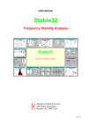
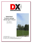
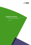
A dB Levels White Paper Dallas, TX USA 214-257-8823 www.dblevels.com Methods for Verification of Network Timing and Synchronization Links By Daniel B. Burch July 2009- UPDATED October 2013 B Contents Introduction B Problem Statement B Previous Options C Recommended Solution C Implementation D Summary D Introduction Guidelines for Network Synchronization and Timing have been adequately chronicled for Network Planners and Engineers; however, there has been a void in materials and procedures to guide local site technicians and maintenance engineers regarding testing of BITS clock input and output links, and troubleshooting of synchronization and timing-related problems in general. Problem Statement Telecommunications site technicians are tasked with maintaining a wide array and vintage of Network Elements, including TDM voice switches, Fiber Optic transmission equipment, Channel Banks, Add-Drop Multiplexers and IP-based routers, gateways, switches and management systems. For the entire Network to be properly synchronized, nearly all of these devices require connections to the Building Integrated Timing Supply (BITS). Equipment installations for local office and field locations were based on prevailing procedures of the day, resulting in a myriad of possible connection arrangements, test access points and cabling conventions. Overall Synchronization Planning was thwarted by failure to properly connect all related Network Elements, fueled by installations which did not follow strict standards. Most locations adhered to some level of Synchronization Planning, so the Network was generally stable for long periods of time. Historically, site technicians rarely needed to work on BITS, so they possess little, if any knowledge or understanding of neither the local BITS system nor its relevance to network troubles. However, as Network transmission rates and channel July 2009- UPDATED October 2013 C capacities have risen, so also have outages related to Network Synchronization. The implementation of Sync Status Messaging (SSM) on T1 and E1 timing links greatly increased reliability and complexity of Synchronization Planning and testing. SSM provides a means for Network Elements downstream from the BITS to be aware of the traceability of the timing signal with a hierarchal system of coded messages. Transmitted “out-of-band” on E1 and the Facility Data Link for T1, SSM allows Network Elements to follow an automatic, pre-determined process for selecting the timing source of the highest reference; thereby eliminating outages due to timing failures. Network Time Protocol (PTP) and Precision Time Protocol (PTP/IEEE 1588v2) are now also widely implemented across carrier networks, supported by little, if any procedure for turn-up and maintenance testing. Currently, site technicians lack: 1. Test equipment to properly evaluate BITS output signals, including readout of critical SSM codes for T1 and E1 signals. 2. Procedures for testing BITS and NTP output links. 3. Training to quickly identify Network Timing and Synchronization problems. July 2009- UPDATED October 2013 Previous Options The common fall-back method has been to closely monitor alarms in the BITS equipment at the System Level, with hopes that individual timing output troubles could be detected at the higher level. However, this is often not the case. Modern GPS-based Network Synchronization Systems do provide alarm monitoring to determine overall system operation, quality and usefulness of the GPS signal, status of antenna cables and antenna operation, and a limited number of output-related faults such as shorted output cables. Troubleshooting methods were generally directed from a distant Network Operations Center (NOC), with the local site technician performing “eyes and ears” function for the NOC engineer. Cards could be swapped, LEDs viewed for activity, etc. However, at some point the NOC engineer must direct the site technician to perform physical maintenance activity such as cable testing, tracing and Network Element connection verification. At this point the local technician was very limited in availability of tools and training. Recommended Solution The solution is to provide telecommunications site technicians with tools and information (procedures) to identify, troubleshoot and correct Network Synchronization and Timing troubles. This must include practical examples for completion of required tasks, analysis flowcharts, and simplified overview of the concepts of Network Timing and Synchronization. This white paper provides directions for connection of laptop PCs, Network Sniffers and analysis of NTP links; and also use of a timing test set, analysis of test results, D corrective measures and installation guidelines for the three most widelyused BITS timing link types worldwide: 1. 2. 3. 4. 5. 6. T1 with or without SSM E1 with or without SSM CC (Composite Clock) Network Time Protocol Precision Time Protocol (IEEE 1588v2) Benefit 1 This white paper will equip telecommunications site technicians to quickly evaluate the quality and usefulness of BITS timing signals, with instructions for testing all the way to the Network Element; and advanced troubleshooting of NTPrelated troubles. This will result in significant reduction in restoral times for timing-related outages, and reduction of costly repeated/chronic trouble reports. Benefit 2 This white paper can be used to, or serve as a guideline for establishing routine maintenance procedures that can reduce or eliminate potential timing-related failures before they occur by introducing a method for remote, long-term monitoring of critical timing circuits. Benefit 3 Lastly, this white paper will provide a framework for testing of new Synchronization Plans as they are implemented, ensuring that the design objectives have been achieved July 2009- UPDATED October 2013 in practice (installation), including recognition of “timing loops” which prove fatal to Network Operations. Implementation To achieve the deliverables in this white paper, the end user company must acknowledge the identified deficiencies, provide minimal to moderate funding of required test equipment, review existing practice and procedure relating to BITS testing at the local site, and finally, condense and distribute the procedures herein, inserting any additional safeguards required by your company. Such additions may include escalation procedures, authorizations for performing routine maintenance, and safety procedures for wrist-strap grounding where required. Summary Since deregulation of AT&T in the 1980’s, telecommunications networks have become interconnected islands of technology, with no supreme arbiter to insure all the rules are obeyed. As these interconnections span the globe, carriers of all sizes can now impact overall network performance and reliability. It is critical that every carrier develop a Synchronization Plan which fits well with the rest of the world, ensuring reliable, selfhealing transmission paths. A key component then, is to properly equip and train telecommunications site technicians to adequately maintain timing and synchronization links at the local level. If not, services will be unreliable and noisy, calls will be dropped, Internet connections will slow, and HDTV images will be irregularly pixilated, ruining the quality so heavily touted by broadband connections. Methods for Verification of Network Timing and Synchronization Links Table of Contents Overview Section Introduction to Timing & Synchronization including NTP, PTP and SSM 1.0……. Timing vs. Synchronization……………………………………………………… 5 1.1……. Wristwatch vs. Metronome……………………………………………………… 6 1.2……. Need for Synchronization in Networks…………………………………………... 7 1.3…….How Synchronization Achieved………………………………………………….. 9 1.4…….Sync Stratum Levels……………………………………………………………… 10 1.5……. Anatomy of a BITS Clock……………………………………………………….. 12 1.5.1…. GPS Receivers…………………………………………………………………… 12 1.5.2…. Input Interface…………………………………………………………………… 13 1.5.3…. Tracking Priority………………………………………………………………… 13 1.5.4…. Holdover Oscillators…………………………………………………………….. 14 1.5.5…. BITS Clock Management………………………………………………………… 15 1.5.6…. BITS Outputs…………………………………………………………………….. 16 1.5.6.1.. Unprotected Mode……………………………………………………………….. 16 1.5.6.2.. Protected Port Mode……………………………………………………………… 17 1.5.6.3.. Protected Full Mode……………………………………………………………… 18 1.5.6.4.. Timing Insertion Mode…………………………………………………………… 19 1.6…… BITS Distribution Shelves……………………………………………………….. 20 1.7…… Sync Status Messaging (SSM)…………………………………………………… 21 1.7.1… SSM in SONET/PDH Networks…………………………………………………. 22 1.8…… Network Time Protocol (NTP) and Precision Time Protocol (PTP)..…………… 23 1.8.1…. The Inverse of Frequency is Time…..…………………………………………… 23 1.8.2…. NTP in the PC…….………………………………………………………………. 25 1.8.3…. NTP via NIST sites………………………………………………………………. 26 1.8.4…. Need for Reliable Time Stamps………………….……………………………… 27 1.8.4.1.. IEEE 1588v2 /PTP for packet/LTE networks ...….……………………………… 27 1.8.5…. Deploying NTP/PTP……………………………………………………………… 29 1.8.6…. Deriving TDM Synchronization from PTP ……………………………………… 31 1.8.7…. Purchase a TDM or PTP Clock?…………….…………………………………… 32 1.9…… BITS Installation Considerations………………………………………………… 33 1.9.1…. The Sync Plan……………………………………………………………………. 33 1.9.2…. Timing Loops……………………………………………………………………. 33 1.9.4…. Site Surveys……………………………………………………………………… 34 1.9.5…. Redundancy Requirements………………………………………………………. 34 1.9.6…. Physical BITS Shelf Siting………………………………………………………. 35 1.9.7…. Antenna Loss Budgets………………………………………………………….. 35 1.9.8…. Pro’s and Con’s for DUC………………………………………………………… 38 1.9.8.1.. Antenna Siting……………….…………………………………………………… 39 1.9.9…. RF Interference Considerations………………………………………………….. 40 1.9.10… Lightning Protection……………………………………………………………… 41 1.9.11… Physical Placement of Lightning Protection Elements…………………………... 42 1.9.12… BITS Output Cabling Guidelines………………………………………………… 43 1.9.13… Connecting BITS Outputs to Network Elements………………………………… 44 1.9.14… BITS Output Test Access Arrangements………………………………………… 44 1.9.15… Connecting BITS to SONET/PDH Network Elements…………………………... 45 Page 1 of 47 © Copyright 2009, 2013 dB Levels, Inc. All Rights Reserved Ver 2.1 10/2013 Methods for Verification of Network Timing and Synchronization Links Troubleshooting Section - Timing and Synchronization Links List of Tables T1……. Effects of Frame Slips……………………………………………………………. 10 T2…… BITS Input Priority……………………………………………………………….. 13 T3…… BITS Output Cable Length Limits……………………………………………….. 43 List of Figures Fig. 1… Timing vs. Synchronization……………………………………………………….5 Fig. 2… Timing & Synchronization of Network Element………………………………… 6 Fig. 3… Single PCM Link…………………………………………………………………. 7 Fig. 4… Multiple PCM Links……………………………………………………………… 8 Fig. 5… Synchronization of Multiple PCM Network Elements…………………………... 8 Fig. 6… External Timing vs. Loop (Line) Timing………………………………………… 9 Fig. 7… External Timing Only……………………………………………………………. 9 Fig. 8… Stratum Levels by Office Hierarchy (the old way)……………………………… 10 Fig. 9… Stratum Levels Now on PAR (the new way)……………………………………. 11 Fig. 10...Synchronization Includes Customer Loops……………………………………… 11 Fig. 11...Basic BITS Clock………………………………………………………………… 12 Fig. 12...BITS Clock Input Interface………………………………………………………. 13 Fig. 13...BITS Clock Output w/Good Input……………………………………………….. 14 Fig. 14...BITS Clock Output w/Failed Input………………………………………………. 14 Fig. 15...Redundant BITS System…………………………………………………………. 15 Fig. 16...Unprotected Output Mode……………………………………………………….. 16 Fig. 17...Protected Output Port Mode……………………………………………………… 17 Fig. 18...Protected Full Output Mode……………………………………………………… 18 Fig. 19...Retimer Mode- Timing Insertion Unit…………………………………………… 19 Fig. 20...PRS Serving Multiple BITS Distribution Systems………………………………. 20 Fig. 21...SSM on T1……………………………………………………………………….. 21 Fig. 22...SSM on SONET/PDH Ring……………………………………………………… 22 Fig. 23...NTP Client/Server Example Query/Response…………………………………… 24 Fig. 24...Microsoft Windows NTP Setup………………………………………………….. 25 Fig. 25...Configuring Microsoft Windows NTPP for Internet Server……………………... 26 Fig. 26...Maintaining Timing in SONET…………………………………….……………. 27 Fig. 26a. Maintaining Timing in Packet-Based Networks……..…………….……………. 28 Fig. 27...BITS System with Built-In NTP Server…………………………………………. 29 Fig. 28...Multiple NTP Servers…………………………………………………………….. 30 Fig. 29...NTP-to-BITS via Ethernet……………………………………………………….. 31 Fig. 30...Modern Combination BITS/NTP System………………………………………... 32 Fig. 31...Timing Loop……………………………………………………………………… 33 Fig. 32...BITS Site Survey of Network Elements…………………………………………. 34 Fig. 33...BITS Location Planning…………………………………………………………. 35 Fig. 34...GPS Antenna Loss Budget……………………………………………………….. 36 Fig. 35...Down/Up Converter, External………….………………………………………… 37 Fig. 35a. Down/Up Converter, Integrated…………..……………………………………… 37 Fig. 36...Typical Antenna Installations…………………………………………………….. 39 Fig. 37...Avoid Metal Surface Areas………………………………………………………. 40 Fig. 38...Result of Inadequate Lightning Protection……………………………………….. 41 Fig. 40...Inside vs. Outside Mounting of Lightning Protection……………………………. 42 Fig. 40a. Lightning Arrester Element………………………………………………………. 42 Page 2 of 47 © Copyright 2009, 2013 dB Levels, Inc. All Rights Reserved Ver 2.1 10/2013 Methods for Verification of Network Timing and Synchronization Links List of Figures, Cont…… Fig. 41...DSX Panel Wiring Scheme………………………………………………………. 44 Fig. 42...DSX Panel w/Bantam Jacks……………………………………………………… 45 References [1.4] Stefano Bregni, Synchronization of Digital Telecommunications Networks, Wiley Press, 2002 ISBN 0-7161550-1, Chapter 4, Page 137. [1.7] Stefano Bregni, Synchronization of Digital Telecommunications Networks, Wiley Press, 2002 ISBN 0-7161550-1, Chapter 4, Page 185. [1.71] David Mills, Computer Network Time Synchronization: The Network Time Protocol, CRC Press, 2006, Chapter 1, Pages 3, 4. [1.8], [1.9] Microsoft Corp., Windows Vista [1.93] dB Levels, Inc. [1.94] TesCom SyncPort 104 rear photo [1.95] TesCom SyncPort 104 System Manual 385-8000 Rev AF, Page 41 [1.97] dB Levels file photo [1.98] dB Levels file photo [1.99] dB Levels file photo [2.1] dB Levels file photo [2.2] dB Levels file photo Page 3 of 47 © Copyright 2009, 2013 dB Levels, Inc. All Rights Reserved Ver 2.1 10/2013 Methods for Verification of Network Timing and Synchronization Links Resources BOOKS: Computer Network Time Synchronization: The Network Time Protocol, David L. Mills, CRC Press 2006, ISBN: 0-8493-5805-1 Synchronization of Digital Telecommunications Networks, Stefano Bregni, Wiley Press, 2002 ISBN 0-7161550-1 JOB AIDES, TUTORIALS, ETC.: TesCom, Inc. www.tescomusa.com Virtual Help Desk for Telecom Technicians- dB Levels, Inc. www.dblevels.com i.H.E.L.P. (interactive Halcyon Electronic Learning Program) www.tescomusa.com CC/T1TIMING TEST SETs: Halcyon TIMS/DDS/T1 Recording Timing Test Sets- TesCom, Inc. www.tescomusa.com T-Com 440B/OPT 31 TesCom, Inc. www.tescomusa.com NETWORK SNIFFER (free versions available for PC) WIRESHARK Network Protocol Analyzer Ver. 1.0.7 (freeware) ©1998-2009 Gerald Combs www.wireshark.org TIMING & SYNCHONIZATION EQUIPMENT: TesCom SyncPort www.tescomusa.com TIMING & SYNCHONIZATION Surveys & Assessments: TesCom, Inc. www.tescomusa.com Page 4 of 47 © Copyright 2009, 2013 dB Levels, Inc. All Rights Reserved Ver 2.1 10/2013 Methods for Verification of Network Timing and Synchronization Links 1.0 The term Timing has historically been associated with Time-Division Multiplexed (TDM) Networks where a Building Integrated Timing Supply (BITS) utilized T1, E1, Composite Clock or other links to synchronize Network Elements. A technician might express, “I’ve got a Timing problem in my office.” Or, “I need to run external Timing to that Channel Bank.” Strictly speaking, this is not Timing; it is Synchronization. Timing is a method for providing a reliable reference of exactly what time it is right now. For example, the answer might be that it’s 10:23:00 or, twenty-three minutes past ten o’clock AM. Note that we still don’t know what time zone we are referencing (EST, CST, PST, etc.) This is more commonly referred to as a Time-Stamp, signifying an exact moment in time. One of the most widely deployed protocols for time-stamping is called Network Time Protocol or NTP for short. When you think of Timing, think Time-Stamps. Synchronization, then, is a means for using a frequency reference to stabilize transmission equipment across a single or multiple locations. Fig. 1 Timing vs. Synchronization Page 5 of 47 © Copyright 2009, 2013 dB Levels, Inc. All Rights Reserved Ver 2.1 10/2013 Methods for Verification of Network Timing and Synchronization Links In some cases, Network Elements require connections for both Timing and Synchronization. For example, a Voiceover-IP Gateway needs to be synchronized on the TDM side, yet requires Network Time Protocol (NTP) for accurate time-stamping on the IP side. Likewise, a SONET/PDH Node may require Synchronization for network traffic and NTP for accurate time-stamping of events like alarms or status changes. Fig. 2 Timing & Synchronization Of Same Network Element 1.1 Allow this analogy to illustrate the difference between Timing and Synchronization: If I ask you “What time is it?”, I’d expect you to look at your watch and tell me the time, not hand me a metronome so we could stay on beat with musical instruments. In fact, if I really am concerned about the time you gave me; perhaps I’ll check several other sources and compare the time displays, arriving at some logical answer. I will use all references available to determine exactly what I believe is the correct time. While that is the premise behind NTP, let’s first examine legacy Synchronization methods. Page 6 of 47 © Copyright 2009, 2013 dB Levels, Inc. All Rights Reserved Ver 2.1 10/2013 Methods for Verification of Network Timing and Synchronization Links 1.2 The Need for Synchronization in Networks Modern technician lingo blurs the line between several aspects of Network Synchronization. In practice, it is normal for the following terms to be interchanged by technicians for the same meaning: Timing, BITS, Clocking, and Synchronization. While the engineering purist objects to this, we will delight technicians worldwide by not making a big deal out of it with exception of the sections relating to IP-based Network Time Protocol (NTP). The introduction of Pulse Code Modulation (PCM) and digital transmission systems into the telephone network resulted in improved quality and efficiencies for transmitting voice and data. A single PCM link worked just fine, as the digital signals were governed by clocks built into the PCM Channel Banks. Switch Channel Bank Channel Bank T1 PCM Database Fig. 3 Single PCM link Page 7 of 47 © Copyright 2009, 2013 dB Levels, Inc. All Rights Reserved Ver 2.1 10/2013 Methods for Verification of Network Timing and Synchronization Links However, when end-to-end connections traversed two or more PCM links, subtle deviations in the Channel Bank clocks allowed frame slips, causing audible clicks in the voice traffic and occasional interruption or slowness of data connections. Channel Bank Channel Bank “Hi, how are you doing?” Switch T1 PCM Audible clicks heard “Hi, how are [ [CLICK] doing?” Fig. 4 Multiple PCM links The solution was to connect all Channel Banks with a common frequency reference, synchronizing the internal Channel Bank clocks. There were actually two clock signals in the Channel Bank- 64kbps and 8kbps, called BIT and BYTE, respectively. These clock signals are utilized to convert analog voice signals into a PCM data stream, aligning the encoders and “Framers” which drive the T1 output signals. Since it was impractical to wire BIT and BYTE clock leads from the Building Integrated Timing Supply (BITS), a composite signal was developed, allowing a single link between BITS and Channel Bank. The composite signal consisted of 64kbps stream with a purposeful error every 8kb, and is called Composite Clock (CC). “Hi, how are you doing? “Hi, how are you doing?” Fig. 5 Multiple synchronized PCM links Page 8 of 47 © Copyright 2009, 2013 dB Levels, Inc. All Rights Reserved Ver 2.1 10/2013 Methods for Verification of Network Timing and Synchronization Links 1.3 How Network Synchronization is achieved By connecting one end of the Channel Bank to a common frequency reference (External Timing), the far end Channel Bank could be configured to derive synchronization from the incoming T1 pulses (Loop Timing also called Line Timing), resulting in synchronization of both Channel Banks. BITS Clock Channel Bank Channel Bank CC T1 PCM External Timing Loop Timing Fig. 6 External and Loop Timing Of course, if both ends of the PCM span had clock sources that were on par with each other, then you could connect the Channel Banks at each end to their respective BITS as shown below. BITS Clock BITS Clock Channel Bank Channel Bank CC CC External Timing T1 PCM External Timing Fig. 7 External Timing only To insure the Building Integrated Timing Supply (BITS) in each office are in sync with one another, a higher-order signal is required for all BITS systems to reference equally. In the USA, this signal is derived from satellites in the Global Positioning System (GPS). Page 9 of 47 © Copyright 2009, 2013 dB Levels, Inc. All Rights Reserved Ver 2.1 10/2013 Methods for Verification of Network Timing and Synchronization Links 1.4 Synchronization Signal Stratum Levels Prior to adoption of GPS for synchronization of BITS systems, earlier attempts to provide network synchronization followed a hierarchical model as shown in Figure 8. A Cesium Beam oscillator provided precision frequency output, and the synchronizing signal cascaded downward through the tiers of switching centers. Stratum Level 1 was the most pure signal available, so as the signal passed through each level (switch, transport, etc.), it was of lesser quality (more jitter, etc.). Therefore, by the time the signal reached the End Office (the switching office closest to customers), it was Stratum 4 in quality. In short, the higher the Stratum Level (1 is highest quality), the higher the level of stability as compared to the ideal. Therefore, as the Stratum levels decrease (1 is best, 2 is lesser quality, 4 is much lesser quality), so then do variances in stability. Think of it this way- the higher the Stratum Level designation/number (i.e.: 4), the more frame slips will occur in the transmission equipment. What does this matter? Table 1 below provides a glimpse. Remember, Stratum 1 is as good as it gets, followed by lesser quality Stratum 2, lesser still quality Stratum 3, and much lesser quality Stratum 4. This is like your golf score- lower numbers are the goal. SERVICE Strat 1 Primary Office Cesium Beam Oscillator Strat 2 Regional Office Strat 3 Toll/Tandem Office Strat 4 End Office Switches, Channel Banks Fig. 8 Stratum Levels- by office EFFECT of SLIPS Voice-compressed A slip will cause a click Facsimile A slip can wipe out several lines Modem A slip can cause several seconds of dropout Compressed video or Video Conferencing A slip can wipe out several lines. More slips can freeze frames for several seconds Encrypted data protocol Slips will reduce transmission throughput. Loss of key Packet data Loss of packets, resulting in degraded throughput and retransmission delays SS7 Networks Errored data Table 1 Effects of Frame Slips [1.4] Page 10 of 47 © Copyright 2009, 2013 dB Levels, Inc. All Rights Reserved Ver 2.1 10/2013 Methods for Verification of Network Timing and Synchronization Links Since GPS-based BITS systems are widely deployed, End Office locations now enjoy the same Stratum Level as peer and Primary Offices. However, Network Synchronization does not end at the local Central Office/End Office. Strat 1 Strat 1 Strat 1 Primary Office Regional Office Strat 1 Toll/Tandem End Office Office Switches, Channel Banks Fig. 9 Stratum Levels on Par Network Synchronization Includes the Customer Loop As new services and bandwidth requirements increased, T1 and fiber optic transmission systems were extended to customer locations. The customer, in turn, connected terminal equipment of equal complexity, often subscribing to service from multiple carriers. In many cases, ring-based, self-healing fiber optic networks deliver optimal reliability in the customer loop. Therefore, transmission systems beyond the local End Office must be included in Synchronization Planning. GPS Antennas Dual T1 w/SSM BITS Dual T1 w/SSM Optical Fiber T NE SO UX M SO N MU ET X NTP Central Office Optical Fiber Optical Fiber Customer Site SONET MUX Customer Site Fig. 10 Sync of Customer Loops Page 11 of 47 © Copyright 2009, 2013 dB Levels, Inc. All Rights Reserved Ver 2.1 10/2013 Methods for Verification of Network Timing and Synchronization Links 1.5 Anatomy of a BITS Clock This overview will equip the reader with concepts of a Building Integrated Timing Supply (BITS) system. Though BITS systems vary in complexity, they really perform several simple tasks. Here’s a block drawing of a basic system: GPS RECEIVER (PRS) INPUT INTERFACE CLOCK MANAGEMENT OUTPUT Fig. 11 Basic BITS Clock 1.5.1 The GPS RECEIVER section contains one or two identical receiver units that provide power to the active GPS antenna, decode signals from multiple GPS satellites, and convert the data into reference signals and time stamps that will be distributed by various output ports. The decoded GPS data and signals are first presented to the INPUT INTERFACE for further processing. There are two configurations for BITS systems: those with integrated GPS RECEIVERS; those with separate GPS RECEIVERS. Since even separated GPS RECEIVERS are usually mounted atop the BITS shelf, we will consider them as a whole. The reason they are separate in large systems is that several distribution shelves may make use of the same GPS RECEIVERS. The separate GPS RECEIVERS may also be labeled Primary Reference Source (PRS), as the literally are the primary source of Stratum 1 for the office. Some PRS systems also contain their own holdover oscillator(s), apart from what may be in the BITS shelf. Page 12 of 47 © Copyright 2009, 2013 dB Levels, Inc. All Rights Reserved Ver 2.1 10/2013 Methods for Verification of Network Timing and Synchronization Links 1.5.2 The INPUT INTERFACE allows several types of signals to “drive” the system, including single or dual GPS, T1, E1 or Composite Clock (CC) and 5MHz or 10MHz from another BITS system or Stratum 1 source. However, other than GPS, all other input signals must be traceable to (originate from) a Stratum 1 source or equiv. Fig. 12 BITS Clock Input Interface 1.5.3 The INPUT INTERFACE, CLOCK and MANAGEMENT sections all work together to determine the best available reference for maintaining stable outputs, with a default “pecking order”. The priority list assumes: GPS is reliable and the external T1/E1 or other signal is from reliable source. While you may change the list in software, typical default is: 1st PRIORITY 2nd PRIORITY 3rd PRIORITY 4th PRIORITY GPS External Signal Internal Holdover Oscillator Free Run Table 2 BITS Input Priority Therefore, if a GPS signal is present, that is first priority and is Stratum 1. If GPS fails, the external input may be considered the next best source. This depends on a couple considerations. Over a period of hours/days, the BITS system will compare the External Signal with the GPS reference. If the signal is of sufficient quality, the system will maintain it in the priority list. Additionally, if the signal is a T1 or E1 with SSM, the system can immediately determine the traceability to a BITS source. This will be explained in detail in the next section. Page 13 of 47 © Copyright 2009, 2013 dB Levels, Inc. All Rights Reserved Ver 2.1 10/2013 Methods for Verification of Network Timing and Synchronization Links 1.5.4 If neither GPS nor External Signal is acceptable, the system will fall back to HOLDOVER. Holdover quality is based on the type of Holdover Oscillator installed in the system. If the GPS or External Signal is not restored within the range of the Holdover Oscillator, the system will degrade to FREE RUN condition. This is to say the output signals are likely at or below Stratum 4 and troubles at the local office are likely. Even though the system is in FREE RUN, at least all the outputs of the same BITS system are pretty close in quality. However, that creates additional problems when SONET equipment is used, as SONET elements contain an internal Stratum 3 clock which may be better than the FREE RUN BITS signals supplied. Again, you will soon discover how the use of SSM can aide in such situations. GPS Antenna GPS RECEIVER (PRS) CLOCK OUTPUT Strat 1 I’M IN CHARGE Fig. 13 Output with good GPS/Inputs The CLOCK section contains the backup oscillators which can “Holdover” the quality of the BITS outputs over time. For example, if you lost both GPS and the external signal, the Holdover Oscillation would maintain as near Stratum 1 as possible. A Rubidium oscillator can hold outputs to Stratum 2 or 2e (almost Stratum 1, but not quite), while oven-controlled crystal oscillator can hold outputs to Stratum 3 or 3e (almost Stratum 2). GPS Antenna GPS RECEIVER (PRS) CLOCK Holdover Oscillator OUTPUT Strat 2e I’M IN CHARGE Fig. 14 Output with failed GPS/Inputs Page 14 of 47 © Copyright 2009, 2013 dB Levels, Inc. All Rights Reserved Ver 2.1 10/2013 Methods for Verification of Network Timing and Synchronization Links There is a big difference in cost between rubidium and crystal oscillators, so some logic behind which is best for you: If your system contains two GPS receivers, then you have one layer of redundancy. In other words, both GPS receivers, antennas or antenna cables would have to fail before any of the holdover oscillators would be utilized. However, if both GPS receivers failed, a rubidium oscillator would “Holdover” at just less than Stratum 1 for several weeks unit you could repair the receiver, antenna or cabling. A crystal oscillator would “Holdover” several days, but at a lower Stratum level than rubidium. Therefore, rubidium buys you longer holdover at higher quality than crystal oscillators. Some companies equip BITS systems with two of every critical component- two antennas, two receivers, two oscillators, two output ports per connected element. This is called Full Redundancy. However, before the second oscillator would be used, both receivers and the primary oscillator would have to fail, so in some cases, it may be appropriate to have a primary rubidium and secondary crystal holdover oscillator. It is highly unlikely (but not impossible) that the secondary oscillator would ever have to carry the day. The decisions for the number and type of receivers and oscillators are governed by your company guidelines and may vary by site. Fig. 15 Redundant BITS System 1.5.5 The MANAGEMENT section of a BITS system is pretty self-evident. That is, it allows communications via Serial and/or Ethernet ports, offers configuration menus, manages and displays (sends) alarms and generally keeps track of the rest of the system. The MANAGEMENT section provides a means for performing simple or exhaustive diagnostics on the BITS system. The most commonly used commands analyze the integrity of the antenna circuit for proper operation; display the number of GPS satellites “seen” and the value of the received signals for timing purposes; the length of time the system has remained at Stratum 1; and other critical issues like condition and status of holdover oscillators. Page 15 of 47 © Copyright 2009, 2013 dB Levels, Inc. All Rights Reserved Ver 2.1 10/2013 Methods for Verification of Network Timing and Synchronization Links 1.5.6 Finally, the OUTPUT section provides physical access for connecting jumpers or cables to each connected Network Element. The outputs generally have been wire-wrap pins, but a variety of modular connector types are in use, including individual female RJ45 or BNC connectors. There is a very wide variety of output types, including T1, E1, Composite Clock (CC), 5/10MHz, 2.048 MHz square wave, RS422/1.5MHz, RS422/8KHz, 1PPS, IRIG-B, NTP, PTP and more! How do you know which output is right for each Network Element? Consult the user’s manual! There are four ways to connect Network Equipment to the BITS system: Unprotected, Protected Port, Protected Full, and Timing Insertion. 1.5.6.1 Unprotected Mode means that the Network Element has only one Sync Input connector (Channel Bank for example), and does not warrant redundant card protection. In this case, an output card, sync cable or Sync Input failure would result in sync loss to the Network Element. While this was standard practice over the years, many companies now demand at least Protected Port Mode. Fig. 16 Unprotected Mode Page 16 of 47 © Copyright 2009, 2013 dB Levels, Inc. All Rights Reserved Ver 2.1 10/2013 Methods for Verification of Network Timing and Synchronization Links 1.5.6.2 As stated above, most companies require single input Network Elements to be protected at least at the card level. This means the primary output is coupled (internally or via a “Y” cable) to an output of the same type on an adjacent output card. The outputs work as a pair, with one working and the other in standby mode. In event of failure, the secondary card is quickly activated so that sync is maintained to the Network Element. NOTEgenerally, protected card arrangements must be configured in the BITS shelf with specific outputs assigned. Some systems do offer automatic protection of cards without the need for “Y” cables. Consult User’s Manuals. Also, make sure the selected outputs are configured prior to connecting any “Y” cables, or you will be shorting live outputs together which may result in card damage. This is called Protected Port Mode. Fig. 17 Protected Port Mode Page 17 of 47 © Copyright 2009, 2013 dB Levels, Inc. All Rights Reserved Ver 2.1 10/2013 Methods for Verification of Network Timing and Synchronization Links 1.5.6.3 In Protected Full Mode, the Network Element will have two Sync Input connectors (example: Input A & Input B or Input 1 & Input 2). These may be wire-wrap or RJ-type connectors. The BITS outputs are taken from adjacent output cards, but the ports are not set up as Protected Port. Rather, the Network Element has two independent sync links so that in event a BITS card or cable fails, the second sync input is unaffected. In this case, both BITS links are active all the time. This is the most preferred method for connecting Network Elements to a BITS system. Fig. 18 Protected Full Mode Page 18 of 47 © Copyright 2009, 2013 dB Levels, Inc. All Rights Reserved Ver 2.1 10/2013 Methods for Verification of Network Timing and Synchronization Links 1.5.6.4 Timing Insertion Mode allows Network Equipment that has no external sync port (no extra pins used just for sync input) to be brought into the same level of synchronization as adjacent Network Elements that have dedicated BITS connections. Basically, the traffic-bearing T1/E1 to the Network Element is looped through the BITS system, where the trafficbearing T1/E1 is “re-timed”. Therefore, the T1/E1 bearer traffic is maintained, but the Network Element is now synchronized with all other Network Elements connected directly to BITS. To the Engineering purist, “re-timer” is a misnomer; however, it is the accepted term for this mode of synchronization. The more correct term “re-synchronizer” is just too clumsy. Fig. 19 Re-timer Mode w/Timing Insertion Unit Page 19 of 47 © Copyright 2009, 2013 dB Levels, Inc. All Rights Reserved Ver 2.1 10/2013 Methods for Verification of Network Timing and Synchronization Links 1.6 BITS Distribution Shelves In larger office locations, a single Primary Reference Source (PRS) may provide Stratum 1 links to one or more BITS Distribution shelves. Recall an earlier discussion that there are two configurations for BITS systems: those with integrated GPS Receivers; those with separate GPS Receivers. Systems without GPS Receivers are referred to as BITS Distribution Shelves. There is no need to install multiple sets of PRS in the same site, so a large building can be surveyed, placing BITS Distribution Shelves at strategic locations. For example, BITS Distributions Shelves may be installed on each floor of a multi-story building, or at distant ends of a large floorplan. This will be determined by the number and type of BITS outputs required, and the distance from the BITS shelf to the connected Network Elements. This will be reviewed in greater detail in the section “BITS Installation Considerations”. Fig. 20 PRS Serving Multiple BITS Distribution Shelves Page 20 of 47 © Copyright 2009, 2013 dB Levels, Inc. All Rights Reserved Ver 2.1 10/2013 Methods for Verification of Network Timing and Synchronization Links 1.7 Sync Status Messaging Sync Status Messaging (SSM) provides a means for Network Elements downstream from the BITS system to be alerted the Stratum Level of the timing signal. With a system of coded messages transmitted “out-of-band” on a T1 ESF or E1 signal, SSM allows Network Elements to follow an automatic, pre-determined process for selecting the timing source of the highest Stratum Level; thereby eliminating outages due to timing failures. For T1-ESF, the Facility Data Link carriers the SSM codes as shown below. GPS Antenna SONET MUX GPS RECEIVER (PRS) T1 SSM – Stratum 1 (PRS) CLOCK OUTPUT I’M IN CHARGE On the T1 Facility Data Link, the message looks like this: Fig. 21 SSM Message on T1 For SSM to be useful, connected Network Elements must be configured with instructions for actions to be taken in event of degradation of the SSM code. For example, a normal SSM message of Stratum 1 (PRS) indicates the T1 or E1 signal is traceable back to a Stratum 1 source. While the SSM is not a guarantee of signal quality, it can be used to automatically alert connected Network Equipment if the BITS knowingly becomes degraded. Page 21 of 47 © Copyright 2009, 2013 dB Levels, Inc. All Rights Reserved Ver 2.1 10/2013 Methods for Verification of Network Timing and Synchronization Links 1.7.1 SSM is especially useful in maintaining sync in SONET/PDH rings. The illustration below shows how SSM helps nodes on a ring network make changes to where each node picks timing off the network. With SSM, the ring is able to automatically reconfigure, maintaining synchronization with no technician interaction, offering ample time for repair of the original fault condition. Fig. 22 SSM Messages on SONET/PDH Ring [1.7] Use of SSM can significantly impact the planning of Network Synchronization, but is fully chronicled in other industry literature. Check REFERENCES Section for more information. The TROUBLESHOOTING section will advise site technicians how to “read” SSM in the network. Again, it is worth noting the SSM does not guaranty signal quality, but does identify traceability. If a T1/E1 signal carries an SSM, then at least it can be traced back to a BITS source at some point. If not, the SSM will say “Don’t Use me”. SSM codes are standardized worldwide, so if equipped with a proper Timing Test Set such as the Halcyon Model GbB310-RITS, technicians can clearly read the SSM associated with T1 and E1 BITS links. The 704A can also evaluate the quality and performance of the T1/E1 BITS link, as well as Composite Clock (CC) BITS links. This will be thoroughly explored in the TROUBLESHOOTING section. Page 22 of 47 © Copyright 2009, 2013 dB Levels, Inc. All Rights Reserved Ver 2.1 10/2013 Methods for Verification of Network Timing and Synchronization Links 1.8 NTP and IP-type timing Outputs As discussed earlier, TDM networks traditionally required only T1, E1, Composite Clock (CC) or similar synchronization links to Network Elements. TDM-based networks required Frequency Synchronization, with some network elements also requiring Phase Synchronization. However, as networks migrate to all-IP (LTE, etc.), the physical-layer mechanisms to support TDM frequency references have been largely eliminated. Therefore, if the new networks are to pass synchronization signals, they must be packet-based. A physical-layer technique known as “Synchronous Ethernet” (Sync-E) has been proposed, but would require 100% replacement of network elements to achieve end-to-end success so at this writing not considered a viable option for most networks. Modern networks also present a mix of copper and fiber-optic topologies, further complicating use of Sync-E due to E/O and O/E conversions. The remainder of this paper will consider packet-based synchronization techniques. 1.8.1 The Inverse of Frequency is Time So, if the network will no longer pass a discrete frequency component, how is it able to carry synchronization signals to network elements? The answer is based on the simple premise that the inverse of frequency is time. Therefore, if one can produce a reliable, accurate flow of time-stamps, a frequency component may be recovered and utilized for frequency and phase references. For three decades, Network Time Protocol (NTP) has been employed to carry time-stamps which resolve to millisecond accuracy in telecommunications, power generation, manufacturing automation, financial transactions and medical applications. However, modern network elements require sub-millisecond accuracy, so for synchronization purposes, NTP has been replaced by a newer protocol entitled, Precision Time Protocol (PTP) and more specifically, the version of PTP known as IEEE 1588v2. One key benefit of PTP/IEEE 1588v2 is use of “Profiles” for the types of networks to be installed. For example, a communications network has different synchronization requirements than a power generation management network, therefore, rather than having a generic PTP which requires the user to manually configure a dozen or more critical parameters in the PTP client or server, a quick-setup is achieved by invoking the appropriate Profile for the network requirements. For example, most telecommunications networks utilize the “Telcom Profile” for PTP, greatly simplifying the installation process especially when adding new clients. Therefore, two different methods for achieving accurate time-stamps are employed in IP networks: NTP and PTP. They are utilized exclusively; they are not mixed in the same network (generally). Page 23 of 47 © Copyright 2009, 2013 dB Levels, Inc. All Rights Reserved Ver 2.1 10/2013 Methods for Verification of Network Timing and Synchronization Links Utilization of NTP/PTP requires a host server, and a remote client. In the example shown below, a PC is connected via Ethernet to a NTP server resident in a BITS system. While this explanation is an oversimplification of NTP/PTP protocol, the process works like this: PC or remote Network Element sends NTP query to the server with a transmit Time-Stamp; server responds with multiple Time-Stamps. The query/response contains information elements that allow the client to calculate round-trip delay of the messages, adjusting for the difference and yielding high accuracy as to actual time within milliseconds (sub-milliseconds for PTP). The PC repeats this process for as many times as necessary to establish the initial setting, updating at specific periods (once/hour, once/day, once/week based on settings). If more than one NTP/PTP server exists, the NTP/PTP client can reference both hosts, further increasing accuracy of the end result. However, for most applications, a single server is adequate. Fig. 23 NTP Client-Server Query/Response [1.71] Page 24 of 47 © Copyright 2009, 2013 dB Levels, Inc. All Rights Reserved Ver 2.1 10/2013 Methods for Verification of Network Timing and Synchronization Links 1.8.2 To better understand NTP, consider the clock in your personal computer. Every PC contains an on-board clock which plods along on its own. This is not an extremely accurate timekeeper, so you may have noticed that over weeks or months the PC clock needs adjusted. Look down into the bottom right corner of your PC screen and observe the time display. If you have several PCs, the time is likely to vary by several minutes or more. However, modern PCs now contain a small program which utilizes Network Time Protocol (NTP) for short which can constantly update the PC internal clock. However, for this program to work properly, the PC must be connected to the Internet at least once per week so it can poll one of several NTP Servers. If you double-click the time display, a window will appear titled “Date and Time Properties”. Depending on the vintage of your PC (WIN2K and previous are doubtful), you should see three tabs; one allows you to adjust the time and date; a second let’s you select the proper time zone; and the third should be labeled “Internet Time”. Fig. 30 Windows Time/Date Screen Fig. 24 Windows NTP Setup [1.8] Page 25 of 47 © Copyright 2009, 2013 dB Levels, Inc. All Rights Reserved Ver 2.1 10/2013 Methods for Verification of Network Timing and Synchronization Links 1.8.3 Click on the Internet Time tab and you can select from a number of sites in a drop-down window the NTP server of choice. In this example, the NTP server maintained by the US National Institute of Standards and Technology is selected. Therefore, at regular intervals (typically once/week), the PC sends an NTP query message to the NTP server, requesting a Time-Stamp. If successful, a message in middle of screen advises the exact time of the update, and also displays the date/time for the next scheduled query. In this case, the PC was updated @ 6:33 PM local time on 4/1/2009, and the next scheduled update will occur at 6:30 PM local time on 4/8/2009. Note you must check the box to automatically synchronize, or you will have to manually click UPDATE NOW at regular intervals of your own choosing. Fig. 31 Auto NTP sync with NIST Fig. 25 Configuring Windows Client to Source a NIST NTP Server [1.9] It is notable that NTP has been around for a very long time, but has only recently been more widely adopted, deployed and utilized. Over the past several years, Network Providers have grown to rely heavily on NTP for time management of all critical network elements, including call processor records for billing systems, network management devices including routers, Ethernet switches and the management side of all switching and transmission systems. Page 26 of 47 © Copyright 2009, 2013 dB Levels, Inc. All Rights Reserved Ver 2.1 10/2013 Methods for Verification of Network Timing and Synchronization Links 1.8.4 Need for Reliable Time-Stamps While you may consider the PC clock to be a mild convenience, consider the benefits of maintaining accuracy of the local clock. Many clients (PC programs) make use of the time stamp for events such as email, bank transactions, stock purchases, ebay activity, etc. Also, Windows uses the clock to maintain files, updates, events so that if needed, critical information can be retrieved to restore from a PC crash. It really is best if you keep the clock current. 1.8.4.1 The use of NTP/PTP has grown way beyond simple timekeeping for administrative and maintenance purposes. Reliable Time-Stamps form the basis for numerous Network Utilization and Performance measuring tools. Customers now demand some form of proof for network performance, such as availability, throughput and latency. Accurate Time-Stamps are the key to delivering real-time reports for network performance. In the drawings below, BITS systems (SyncPort) are used to supply T1 and PTP to both TDM (SONET) and Packet (LTE) networks. The PTP method is also useful for Pseudo-Wire Emulation (PWE) Network Elements. PWE is the method for transporting TDM signals like T1 across a packet networks. Fig. 26 Maintaining Timing in SONET [] Page 27 of 47 © Copyright 2009, 2013 dB Levels, Inc. All Rights Reserved Ver 2.1 10/2013 Methods for Verification of Network Timing and Synchronization Links Fig. 26 Maintaining Timing in Packet-based Networks [1.92] Page 28 of 47 © Copyright 2009, 2013 dB Levels, Inc. All Rights Reserved Ver 2.1 10/2013 Methods for Verification of Network Timing and Synchronization Links 1.8.5 There are two basic NTP implementations: SNTP and NTP. If you are going to install a single server in a small network (less than 50 or so clients), Simple Network Time Protocol (SNTP) will work fine. However, if your plan is larger, serving hundreds of clients (PCs, Network Elements, etc.), then you may need full NTP. Full NTP has many expanded capabilities for discovering adjacent NTP servers, configuration preferences such as ability to serve as a primary or secondary time source, and more. These are fully chronicled elsewhere; check RESOURSES section for more info. In the illustration below, the BITS system contains a SNTP Server function, providing Time-Stamps to multiple Network Elements and PCs at the site. It is possible to utilize a NTP server over several “HOPS”, however this should be limited to less than 6 HOPS for critical applications. Fig. 27 BITS w/Built-In NTP Server Page 29 of 47 © Copyright 2009, 2013 dB Levels, Inc. All Rights Reserved Ver 2.1 10/2013 Methods for Verification of Network Timing and Synchronization Links NTP is most accurate when multiple NTP servers are deployed. One or two servers will source back to GPS, and the remaining servers will poll each other. This mesh configuration creates an extremely stable time reference system which may achieve nanosecond accuracy, with redundancies to eliminate network outages. Fig. 28 Multiple NTP Servers Page 30 of 47 © Copyright 2009, 2013 dB Levels, Inc. All Rights Reserved Ver 2.1 10/2013 Methods for Verification of Network Timing and Synchronization Links 1.8.6 TDM Sync from an IP-Based Network NTP may also be utilized to provide T1, E1 or other signals to locations where it is not possible or convenient to install an exterior GPS antenna. First, you must establish a site that will be GPS-based and install a BITS system with NTP capabilities. This will be termed a Grandmaster Clock. At one or more remote sites, a “very small footprint” Edge Client/Edge BITS device accepts the NTP feed over Ethernet connection, and converts the precision information into stable BITS outputs such as T1, E1, 1Pulse-Per-Second or 5/10MHz. The benefit of this arrangement is that the Grandmaster Clock is only moderately priced, but the Edge Client devices are usually priced under $2,000. Therefore, one Grandmaster can provide Stratum-quality synchronization signals to a dozen or more end locations served only by your internal Ethernet network. Fig. 29 NTP-to-BITS via Ethernet [1.93] Page 31 of 47 © Copyright 2009, 2013 dB Levels, Inc. All Rights Reserved Ver 2.1 10/2013 Methods for Verification of Network Timing and Synchronization Links 1.8.7 Purchase a TDM or PTP Clock? The decision of which time protocol to use will be based on the current and future design of you IP network. NTP may be utilized in almost any network configuration that meets minimal guidelines. However, 1588 requires some additional network topologies and performance enhancements already are in place, such as QoS. Therefore, significant improvements may be required for existing networks. However, when developing a new network, such issues will likely be mute. Timing and Synchronization vendors will gladly assist in reviewing your needs. If the predominance of your output requirements are Synchronization based (T1/E1, CC, etc.), then the best solution is to add NTP capability to a new or existing BITS system. However, if the majority of your needs are on the IP side, purchasing a GPS-based NTP server is best. Most commercial NTP servers also have a limited number of Synchronization outputs as well, so today you can have both in a single package. Below is the rear view of a modern combination BITS/NTP system available in ANSI or ETSI versions that may be equipped with single or dual GPS Receivers, up to 2 external inputs, single or dual Rubidium, crystal or mix of Rubidium/crystal holdover oscillators and 64 outputs that can be programmed by port, allowing you to “skinny down” or “fatten up” as needed. The system also offers IP connections for SNMP management and up to two ports of SNTP, and IEEE 1588 v2, all at only 2 Rack Units (RU). Just a few years ago, this same capability would have consumed 10 RU. The SNTP option for this system sells for under US $800. Today there is no reason to buy separate elements for providing Synchronization and Timing outputs. Fig. 30 Modern Combination BITS/NTP System [1.94] 1.9 BITS Installation Considerations Page 32 of 47 © Copyright 2009, 2013 dB Levels, Inc. All Rights Reserved Ver 2.1 10/2013 Methods for Verification of Network Timing and Synchronization Links This section provides an overview of basic considerations for typical BITS system installation at a site. The need for BITS at a location should be driven by Network Planners utilizing an instrument called a Synchronization Plan or Sync Plan, for short. 1.9.1 The Sync Plan should be the guiding reference tool for all BITS installations; decisioning of the BITS type, size and redundancy; connecting of Network Elements; and management/troubleshooting directives. Routine maintenance of BITS output links does not require access to the Sync Plan. Failed output cards or cables, improper output configuration and basic BITS system analysis are pretty logical tasks. If Lightning damages one of the antennas; replace the antenna. If an Output card fails; replace output card. However, persistent, unexplained troubles require a closer look at the entire synchronization strategy. Frequent dropped calls, sporadic errors in 56/64kbps DDS and/or T1/E1circuits, bearer traffic issues on ISDN channels, SS7 failures, unexplained trunk failures and frequent multiple alarms are all indicators that synchronization problems exist. 1.9.2 When contacted for technical support on difficult synchronization troubles, experts will always want a look at the Sync Plan. You have to know where synchronization starts (originates) and where it ends (what’s connected). It is crucial that Timing Loops be identified and corrected, or the entire network will collapse upon a GPS failure. A Timing Loop occurs when a BITS system is in some way referencing an input signal that is directly or indirectly derived from one of its own outputs. Fig. 31 Timing Loop Page 33 of 47 © Copyright 2009, 2013 dB Levels, Inc. All Rights Reserved Ver 2.1 10/2013 Methods for Verification of Network Timing and Synchronization Links 1.9.3 What and How Many? As previously discussed, any BITS installation should be driven by specific dictates of the Synchronization Plan (Sync Plan). If the office is small with fewer than 64 Network Elements to be connected, a Site Survey will provide the details from which a Sync Plan may be developed. 1.9.4 A basic site survey consists of an audit of all Network Elements (NEs), determination of the type of synchronization signals required by each NE, availability of suitable power and ventilation, location and suitability of existing grounding scheme for the lightning arrestors, and access to a clear sky view on the outside of the building. From this survey, the Sync Plan will identify the size, type and number of BITS systems required for the site, including redundancy requirements. Network Element Alcatel Channel Bank Alcatel Channel Bank Cisco SONET 5ESS Fujitsu DSLAM Brand X MUX Type Input Required CC CC T1 w/SSM T1 CC LINE-T1 Number of Inputs 1 1 2 2 2 * Additional Input Requirements Number of Additional Inputs NTP 1 NTP 1 Distance to BITS 30 ft 120 ft 84 ft 140 ft 420 ft 35 ft Fig. 32 BITS Site Survey- NEs Once the audit of Network Elements is completed, it is a simple thing to tally up the number of required outputs by type. Note in the example above, one Network Element (Brand X MUX) has no external sync input, so will have to be Line Timed on the traffic bearing T1. This can be accomplished via a Timing Insertion Unit where the traffic bearing T1 is looped into and out of the BITS system. In most small offices, all Network Elements will be within allowable distance limits from the BITS system. Larger offices, especially with multi-floor buildings will require up to several BITS Distribution Shelves. The BITS Distribution Shelves have to be engineered so that the allowable output cable distances can be met without violating the distance limits between the BITS Distribution Shelf and Primary Reference Source locations. These distance limits will be fully explored below. Redundancy requirements vary and based on each companies synchronization philosophy. Larger companies usually opt for dual antennas, antenna cables, GPS receivers, and holdover oscillators, employing Protected Card or Protected Full output redundancy. For companies with SONET/PDH networks, placement of several non-redundant clocks around the ring may eliminate the need for fully redundant systems at each site. 1.9.5 Historically, redundancy was thought of as ordering two of each critical component within the system proper. However, due to shrinking system footprints, a new concept has emerged called “Shelf Redundancy”. With Shelf Redundancy, you order a non-redundant system times 2, meaning you mount identical systems together, achieving 100% redundancy down to the backplane. You still have two antennas, GPS receivers, holdover oscillators and outputs, they are just associated with completely separate shelves. This arrangement is frequently lower cost that a fully-loaded single-shelf redundant system, as newer technology offers significant improvements in “cost per port” as compared with older “hardened” designs. Page 34 of 47 © Copyright 2009, 2013 dB Levels, Inc. All Rights Reserved Ver 2.1 10/2013 Methods for Verification of Network Timing and Synchronization Links 1.9.6 Where? Planning and installing a BITS system into an office is a daunting task. The two prime considerations relate to the distance from a proposed equipment rack (bay) location to the majority of Network Elements to be connected; and the distance from the bay to an outdoor location where GPS antennas will be mounted. Fig. 33 BITS Location Planning The most labor-intensive tasks associated with installation of a BITS system relate to: installing antenna and antenna cabling; running cables between BITS outputs and Network Elements. Of the two, antenna installation can be the most difficult, so we will examine these issues first. 1.9.7 GPS signals arrive at the antenna in the neighborhood of -130dBm, which also happens to be near the upper range of sensitivity for GPS Receivers. Most commercial GPS antennas feature 30dB of gain; therefore the loss budget for antenna cabling is around 15dB. Antenna line loss varies by the size, type and gauge of the cable. For example, coaxial RG-58U cabling burns through most of the 15dB loss budget (with margin) at around 75 feet. This incorporates losses associated with connectors and insertion loss of the Lightning Arrestor and connections. Therefore, antenna runs longer than approximately 75 feet require lower loss cabling such as RG-213U, LMR-400 or LMR-600 based on distance requirements. Alternative schemes are available that utilize fiber optic cabling or frequency conversion units which allow longer runs of RG-58U (up to 1,500 feet). Page 35 of 47 © Copyright 2009, 2013 dB Levels, Inc. All Rights Reserved Ver 2.1 10/2013 Methods for Verification of Network Timing and Synchronization Links Cable Type RG-58 RG-213 RG-59 RG-8 LMR400 LMR600 LMR1700 15 dB Loss* 75 feet (23 m) 125 feet (38 m) 150 feet (46 m) 250 feet (75 m) 275 feet (84 m) 450 feet (137 m) 1,150 feet (350 m) Loss per 100 ft (30 m) 20 dB 12 dB 10 dB 6 dB 5.4 dB 3.3 dB 1.3 dB Fig. 34 Antenna Loss Budget [1.95] Page 36 of 47 © Copyright 2009, 2013 dB Levels, Inc. All Rights Reserved Ver 2.1 10/2013 Methods for Verification of Network Timing and Synchronization Links The larger size LMR cables can get quite expensive, requiring special tools and skill for installing connectors. At some point there is a cost advantage to installing a down/up converter which will allow cheaper RG-58U cable runs of up to 1,500 feet. Fig. 35 External Down/Up Converter (copper or fiber) Fig. 35a Integrated Down/Up Converter (copper or fiber) Page 37 of 47 © Copyright 2009, 2013 dB Levels, Inc. All Rights Reserved Ver 2.1 10/2013 Methods for Verification of Network Timing and Synchronization Links 1.9.8 Pro’s and Con’s for Down/Up Conversion The use of Down/Up conversion should be carefully considered, as there are significant implications for long-range office planning, sparing costs and dependence on proprietary equipment. Here are the Pro considerations: 1. Allows use of lower cost RG58U cabling for extreme antenna lengths Conversely, here are several Con considerations: 1. GPS signal may not be shared with other devices (connects only to the specialized Up converter) 2. All Down/Up elements are vendor proprietary (vendors support/longevity) 3. Many Down Converters require separate power at antenna 4. Requires non-standard lightning arresters 5. An additional point of failure 6. Complicates troubleshooting procedures 7. Expensive to maintain (replacement parts) Through installation of an active GPS splitter (unity gain or gain), standard L1-band GPS signals (1575 MHz) may be shared among many GPS devices in the same building. However, if Down/Up converters are employed where the Up-conversion is inside the clock, no signal sharing is possible. This greatly limits use of the incoming signals which will require additional antennas for any additional equipment. Most clocks utilizing Down/Up conversion utilize only a single antenna, regardless of the number of internal GPS receivers. However, if you are spending extra money to achieve redundancy in major elements such as GPS receiver, oscillator, etc., it makes no sense to limit the installation to a single antenna. The antenna is the most exposed part in the entire system, prone to damage from lightning, rodents/animals, theft or vandalism so why spend the money for redundancy everywhere but the antenna? However, installing twin antennas in Down/Up systems is usually cost prohibitive. Use of standard L1-band GPS antennas provides greater flexibility in long-term maintenance for antennas and lightning arresters. If the OEM of Down/Up shutters operations or drops support of your scheme, the clock is useless. However, there are several quality manufacturers for antennas and lightning arresters, significantly reducing the risk of dealing with vendor-proprietary elements. Page 38 of 47 © Copyright 2009, 2013 dB Levels, Inc. All Rights Reserved Ver 2.1 10/2013 Methods for Verification of Network Timing and Synchronization Links 1.9.8 Antenna Siting The most critical step in BITS installations is careful selection of the antenna site. If you get this wrong, the BITS clock will be plagued by intermittent troubles for the life of the system. While it is imperative to adhere strictly to the antenna cable loss budgets, this will be for naught if the antenna is located in the presence of interfering signals or blocked from a clear view of the sky. Basically, the antennas need to be installed with no less than 30 feet of separation. In fact, use the most separation your cable length will allow. The extra length could save one of the antennas in event of a lightning strike, tree limb, or vandalism (shotgun blast, etc.). Locating antennas away from public view is highly desirable. The antennas should not be the highest object on the roofline. Rather, they should have a clear view of the sky with an angle of at least 45 degrees, and also a view of the distant horizon if possible. Use of conduits is suggested, mostly to protect the cable from deterioration. Avoid tree branches, radio transmission antennas and low placement on high vertical walls. Fig. 36 Typical Antenna Installations [1.97] Page 39 of 47 © Copyright 2009, 2013 dB Levels, Inc. All Rights Reserved Ver 2.1 10/2013 Methods for Verification of Network Timing and Synchronization Links 1.9.9 RF Interference and Metal Surfaces It is not recommended to locate the antennas near broad metallic surfaces as shown below. The metal can potentially act as a reflector for interfering signals and also be a magnet for lightning strikes. This installation looks beautiful, but should be relocated. Fig. 37 Avoid Metal Surfaces [1.98] Do not install GPS antennas near transmitting antennas or high-power antenna feed lines. RF leakage and direct radiation can wipe out or intermittently interfere with the GPS signals, which are at -125dB. Take note of any radiating elements and also beware of “line of sight” path violations where the GPS antenna is placed in the radiating pattern (RF path) of nearby antennas. If the loss budget is respected, the antennas free of interfering signals and away from broad metal surfaces, and the lightning arrestors properly connected, the BITS clock can provide decades of worry-free service. However, if you break the rules, be prepared for intermittent problems and lots of nighttime work tours. Page 40 of 47 © Copyright 2009, 2013 dB Levels, Inc. All Rights Reserved Ver 2.1 10/2013 Methods for Verification of Network Timing and Synchronization Links 1.9.10 Antenna Lightning Protection As previously discussed, the antenna element is the most likely point of failure in a BITS system (excluding configuration errors). It should go without saying that any element that breaches the office walls should be adequately protected from delivering harmful voltages into the equipment room. Failure to do so routinely results in failures as shown below, which can cost upwards of $8,000 to repair. Fig. 38 Result of Inadequate Lightning Protection [1.99] For active GPS antennas, special protection devices allow normal operation and isolation from ground except the duration of a lightning strike. The isolation and protection elements activate and, if not damaged or destroyed, faithfully return to the previous state. It is critical to observe the manufacturers recommended installation procedure for lightning protection hardware. Failure to do so could actually increase the chance of permanent damage to the BITS system. Page 41 of 47 © Copyright 2009, 2013 dB Levels, Inc. All Rights Reserved Ver 2.1 10/2013 Methods for Verification of Network Timing and Synchronization Links In addition to the manufacturer’s instructions, local building codes must also be understood and applied. The subject of grounding is very important and each site likely is equipped with appropriate grounding systems. The building engineer should be consulted to locate the most appropriate grounding connection point for the antenna lightning arrestors. If not appropriately installed, these connections could introduce hazardous and destructive transient voltages into equipment ground circuits. The point is you cannot merely grab any nearby ground; lightning protection grounds are usually routed directly to the main ground buss away from normal equipment grounds. Below is a typical lightning arrestor arrangement. Note the Isolation Ground Adapter which actively ground the shield during a strike. 1.9.11 Indoors or Outdoors? Obviously the antennas are placed in an outdoor environment, but what about the lightning protection kit? Experts are split on two approaches: install protection right at the point the antenna cable penetrates the building (outside); install protection at the nearest point the antenna cable enters the building (inside). Both concepts are radically opposed, yet both agree that the point of entry or the wall through which the antenna cable passes is the right spot. This stops the lightning surge from traversing all the way into the equipment room. This will, or course, be governed by local ordinance (codes) and company policy. Fig. 40 Inside vs. Outside [2.1] Fig. 40a Lightning Arrester [2.1] Page 42 of 47 © Copyright 2009, 2013 dB Levels, Inc. All Rights Reserved Ver 2.1 10/2013 Methods for Verification of Network Timing and Synchronization Links 1.9.12 BITS Output Cabling This section will explore the process for connecting Network Elements to the BITS outputs. Recall our earlier discussion that the Sync Plan should drive all requirements for connecting Network Elements, provisioning links and ensuring no Timing Loops are constructed. The Sync Plan should also yield an assignment record that instructs provisioning out each output, designation of protected paths, and CLLI code or other identifying code for the connected equipment. Some BITS systems offer internal port assignment logs to maintain on-site records. However, this information must be routinely updated or reliability will suffer as the network undergoes rearrangements. For troubleshooting efforts, nothing is more important than a record of output assignments on a per-card basis. As previously discussed, each output type carries a set of requirements for staying within the useful range of proper operation. While the main qualifier is cable length, this can be greatly impacted by the size, type and gauge of cabling used to connect the Network Elements. Assuming proper cables installed, typical distance limits are shown below. Output Type T1 E1 CC- Composite Clock 2.048 MHz Square Wave RS422- 1.5 MHz RS422- 8 KHz 5/10 MHz Distance Limit 130 feet 100 feet 1,500 feet 100 feet 130 feet 1,500 feet 30 feet Table 3 Output Limits For T1/E1 connections, it is important to employ a suitable cable which is rated for T1/E1 signals. Inexpensive finegauge UTP will yield poor results. The suggested cable is two conductor twisted pair, shielded, 22-gauge solid copper with a drain wire. A drain wire is a bare, solid copper wire that is wrapped tightly against, but outside the shield. The wire connects to a grounding point at the Network Element to eliminate noise and signals which may be couple to the cable. In most cases, the drain wire is not attached at the BITS end, but is insulated with heat shrink tubing. Unless dictated by local code or company policy, it is not recommended that both ends be grounded, as this will result in a ground loop that may actually cause more noise to be coupled to the inner wires. When it comes to selection of wire types, check the manufacturer’s recommendations, as they likely have tested their equipment with many cable types and best positioned to provide this information. The distance limits shown above are for general planning and may vary based on the type of output cards installed. However, installing longer runs of cable than permitted will significantly degrade the signal, which could lead to intermittent operation. For existing installations, this may pose a problem, as the existing wiring may have been in place for many years. In this case, use of a test set to measure the quality and usefulness of the signal is in order. This will be fully explained in the TROUBLESHOOTING section. Page 43 of 47 © Copyright 2009, 2013 dB Levels, Inc. All Rights Reserved Ver 2.1 10/2013 Methods for Verification of Network Timing and Synchronization Links 1.9.13 Connecting BITS to Network Elements Multiple wiring schemes may be encountered when connecting cables to BITS systems. For many years, wire-wrap was the preferred method and many modern systems have maintained that feature. However, this has largely been replaced by standard RJ48 and other connections which require much less space in the equipment rack. 1.9.14 To aide in troubleshooting efforts, many companies also wire BITS Outputs through test points such as Digital Signal Cross-connect (DSX) panels. The BITS Output circuit can quickly be monitored with a test set for repair efforts. As shown below, the BITS Output signal can be wired through the DSX panel so that Monitoring, Testing or Patching can be quickly achieved, greatly reducing troubleshooting time. This process fully described in Troubleshooting section. Fig. 41 DSX Panel Wiring Scheme Page 44 of 47 © Copyright 2009, 2013 dB Levels, Inc. All Rights Reserved Ver 2.1 10/2013 Methods for Verification of Network Timing and Synchronization Links Two basic types of DSX Panels are prevalent: Bantam Jack and RJ45 Jack. Both types are shown below. Fig. 42 DSX Panel with Bantam Jacks Fig. 43 DSX Panel with RJ45 Jacks Page 45 of 47 © Copyright 2009, 2013 dB Levels, Inc. All Rights Reserved Ver 2.1 10/2013 Methods for Verification of Network Timing and Synchronization Links 2.0.0 Clock Families Unfortunately, much of the GPS Clock world remains fractured in terms of scalability. Few clock manufacturers utilize common parts between platforms, with completely separate requirements for installation practices, antenna requirements and sparing policies. Throughout this whitepaper, we have utilized the timing products from TesCom, Inc. including the SyncPort line of scalable clocks and a “small-footprint” GPS/PTP client clock. All three models of the SyncPort line (1 RU, 2 RU, 3 RU) utilize the same antennas, lightning arresters, output cards and connector arrangements, Ethernet NTP/PTP/Management cards, System commands, SNMP and management conventions, GUI pages, menu titles, front-panel LED scheme and more. So you can use the 1 RU in small offices (or as a PTP client/slave), and the 2 RU or 3 RU in larger offices while keeping most maintenance requirements the same across all offices. All three shelves can operate in IEEE 1588 PTP Grandmaster or Client/Slave mode, and their IEEE 1588 PTP pricing is a fraction of the cost for competing systems. All SyncPort systems offer multiple AC and DC powering options, over 200 output types, multiple means of management and in many cases are “drop-in” replacements for legacy clocks (of any manufacturer). The 1 RU shelf offers up to 32 outputs including IEEE 1588v2 PTP; the 2 RU shelf offers up to 64 outputs including IEEE 1588v2 PTP; the 3 RU shelf offers up to 104 outputs including IEEE 1588v2 PTP. Many outputs also available in optical format, and IEEE 1588 PTP available in 100BaseT or Gigabit Ethernet. These clocks are all “Made in the USA”. All SyncPort datasheets available @ www.tescomusa.com. See Next Page Page 46 of 47 © Copyright 2009, 2013 dB Levels, Inc. All Rights Reserved Ver 2.1 10/2013 Methods for Verification of Network Timing and Synchronization Links SyncPort 32 SyncPort 64 SyncPort 104 This concludes the Overview Section. Page 47 of 47 © Copyright 2009, 2013 dB Levels, Inc. All Rights Reserved Ver 2.1 10/2013