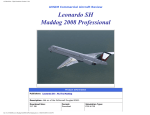
1
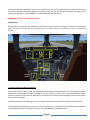
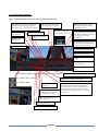
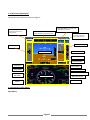
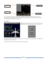
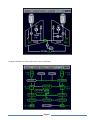
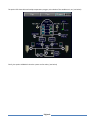
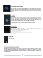
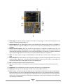
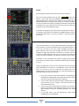
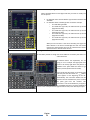
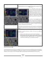
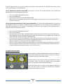
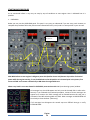
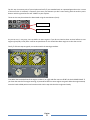
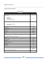
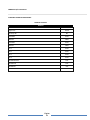
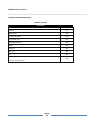
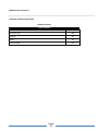
USER MANUAL CONTENT Gauges detail……………… ……………………………………….. 3 Starting engines procedure ……………….…………………. 16 Checklist ……………………………………………………………….. 18 Página 2 This product has two mode panels: 2D or Virtual cockpit. Every panel will be explained here and we hope you know all functions included. We warning about this functions are no real with the real plane (obviously not apply for real flights), only apply to fly in the MICROSOFT® FLIGHT SIMULATOR and you enjoy it. WARNING: Do not use with real flight. Gauges detail Know initially the cockpit of your airplane. Next we show you the position of the gauges in the virtual cockpit and 2D panel. This way you will be able to understand where you must be located to the moment to verify the corresponding checklist. 2 1 8 6 3 4 7 5 9 10 11 Speed brakes Throttle Parking brakes Lever flaps 1.- Master caution and Warning switches When these buttons of alert are ON, you must put special attention of immediate form to the EICAS display where it appears the corresponding message according to the type of alert by color. If it is the YELLOW button (Master caution), it indicates that it must pay attention in permanent form to some event that happens but that momentarily does not offer any danger. Instead if the button is red (Warning switches), it indicates that there is a problem for solving of extreme urgency. The procedure to continue there is to press the button is ON for reset it and to give for understood you pay attention to the problem indicated in the EICAS in the part of SYSTEM MESSAGE. (See below part 5). Página 3 2.- Guidance panel (Autopilot) Here is located all buttons and commands to guide automatic flight. SRC (Source) : In this model it has assigned the function to select the frequency NAV that it goes away to use for navigation: NAV1 or NAV2. HDG: Heading activation switch A/T: Auto throttle switch. To arm it you should click on knob SPEED. SPEED: Knob selector of speed (IAS or MACH). Click on it to arm auto throttle. (indicated in PFD) YD: YAW Dumper switch HDG SEL: Heading selector knob. VNAV: Vertical navigation switch to follow altitudes indicated in FMS for every navigation point. AP: Autopilot activation switch FLCH: Flight level change, click to start climb or descent to flt indicated in ALT SEL. When the altitude is reached, the system return to ALT switch automatically. ALT: Hold altitude switch. Select only to maintain flight level selected when it reached or level to flt actual. Barometric set controls ALT SEL: Flight level knob selector. FPA: Flight path angle switch. FPA SEL: Flight path angle selector. VS: Vertical speed switch. Click to change of flight level. VS SEL: Vertical speed selector knob. The following ones are the functions of these two buttons: OFF, VOR1, ADF1, FMS OFF, VOR2, ADF2 V/L (VOR / LOCALIZER): Change to navigation by VOR FMS: Change to navigation by FMS (GPS) APP: Glide slope switch (approach) BANK: reduce the grade of bank of the plane of 27º to 17º when it is in way HDG, VOR or NAV. NAV: Activate NAVIGATION follow VOR or FMS mode. FD: Flight Director Switch CRS: Course selector VOR navigation Página 4 MINIMUMS: It allows establishing the minimums of flight level in the radio altimeter to determine the moment in which it is necessary to take decision to abort approaches or near of the terrain. The status established in radio altimeter as minimums it is from 0 to 999 feet. 3.- PFD (Primary flight display) This panel shows information about the flight so: Autothrottle speed indicator: This display area shows the speed selected. Flight level selected: This display area shows flight level selected. Mode annunciators: This display area shows Autopilots commands activated. Vertical speed selected: This display area shows vertical speed selected. Altitude display Airspeed display Attitude display Vertical speed display Glide slope guides Barometric display Ground speed Course selected Heading selected Next waypoint (VOR or FMS) Wind direction and speed Time distance to next waypoint HSI display Frequency COMM1 DME to next waypoint Frequency NAV1 4.- MFD (Multi function display) Map display: Página 5 Map options, including TCAS Flight plan Show TERRAIN ZOOM Map + or - Is very important you understand in Virtual cockpit the MAP only is showed OUT of the display because it take information of GPS of the FS and this option is incompatible with 3D Gauges in same display. However in 2D panel the map appear in same display of other functions. System display: This display shows all systems of the aircraft. Just click on the option SYSTEM (SYS) and a menu will be displayed with the next options: The option SYS show the information as upon picture. The information show temperature, gross weight, battery information, pressure in engines, etc. The option FUEL show fuel system and xfeed between tanks, (see below) Página 6 The option ELECTRIC show the system and its values, (see below) Página 7 The option ECS show cabin and cockpit temperature, oxygen, recirculation of the condition air, etc. (see below) Finally, the option HYDRAULIC show the system and its values, (see below) Página 8 5. EICAS (Engine instrument and crew alerting system) The EICAS contains the complementary information needed by the crew to have the certainty of what happens on the outside from the plane or to the interior of the same one. This screen contains: CAS (crew alerting system) window Primary engine instruments (N1, N2, ITT and fuel flow) FUEL QTY (fuel quantities) LANDING GEAR (landing gear position) OIL (engine oil pressure and temperature) VIB (engine vibration) APU (auxiliary power unit output and temperature) CABIN (cabin pressure environment) SLAT/FLAP/SPDBRK (flap, slat, and speedbrake position) TRIMS (trim position indicators). Página 9 6. IES (Integrated electronic standby) This screen help to the ADI or indicator of attitude that works normally in the PFD, but if it failure, this instrument is auxiliary support.Additionally it includes the information of altimeter and speed in the same place (right hand and left side respectively) like it appears in the ADI of the PFD. 7. Autobrake This knob prepares the brakes and spoilers system before to landing. When the aircraft touch on ground, if the system is set as RTO the brakes should be activated automatically depending the speed. The knob return to OFF or RTO when the aircraft reach 35knts. Other option is set as LO (low) where the brakes pressure is low, MED (medium) and HI (High). In every one option the knob return to OFF when the speed reach to 35knts. 1 2 8. Stand by clock The time (hour) indicated in this gauge is in ZULU time. Also this instrument works as chronometer. The 4 buttons or options of configuration: 1.- SET, who places in zeros the chronometer. 2.- It activates the chronometer. 3.- It allows to know the current date and to change to way clock. 4.- It returns to zero the time of flight. 3 9. Landing gear Lever landing gear. 10. FMS (Flight management system guidance) Our product has a FMS but different to other products, our instrument DO NOT USE AIRACS. Our instrument is based on FLIGHT PLANNER of your Flight Simulator and for this reason is very simple to use it. The first time is creating minimum TWO points: Departure and Arrival. The other way points may be inserted in the flight plan as you wish, just follow the next steps. Página 10 1. Display page: It indicates quantity of pages and number of actual page. To select the following one or the previous one touches PREV or NEXT. (5) 2. Active frequency: On this page (Radio) it works as the button ACTIVE changing the frequency in STANDBY for ACTIVE. The active frequency ALWAYS it is the first one in dark color, the frequency in white color is in STANDBY. 3. Modify stand by frequency: With this button the radio frequency is modified in STANDBY status only. The active frequency CANNOT BE MODIFIED, only is possible changing in standby. Press this button and with the numerical keyboard type the frequency (You do not need digit points nor commas, it is already predefined) up to complete 6 digits with zeros come the case and that way the frequency is established. 4. PERF: This button opens the page of PERFORMANCE of the FMS, which contains basic information of the plane. 5. PREV and NEXT: With these buttons you change to next page or back on an active page on the screen. If the number of page is bigger than 1, both buttons will be functional for go to next or to back. On the page 2 you will find the possibility to select frequencies ADF in the RADIO option. 6. FPL: If clicking the page the FLIGHT PLAN will be open. 7. CLR: Click to correct errors. For example if you enter a frequency wrong, press CLR and the frequency old return. 8. Numeric key: This keyboard uses to enter the numbers of frequency on the RADIO page. 9. RADIO: Open or return to first page upon showed in the picture. (Radio functions) 10. CB: This button is used on the page FPL (Flight Plan) to re-calculate the altitudes of every point. Nevertheless we do not advise to you use it to calculate automatically when the list is very extensive because it is possible that you can commit errors or leave flight levels in ZERO that the pilot can obviate and trust to the calculation of the system. Do these calculations in manual way and edit them according to the waypoint. We explain the way of doing it in next points. Página 11 Procedure to modify a frequency in stand by and to change it to ACTIVE. See the image of the left side and continue the next instructions: Click on the button indicated with the color YELLOW -----, when there appears a cursor, digit with the NUMERICAL keyboard indicated in the same YELLOW color in the graph, the number of the frequency UP TO COMPLETING 6 DIGITS. Example: If the frequency is 113.90, key 113900. If you do not complete the sequence of 6 digits, the box will remain opened to continue key. If you wrong and want to correct, press the button CLR, located at the end of the keyboard of TEXT. To activate the frequency click on the button marked with color RED ---in the graph of the left side. The frequency in STANDBY change to the first line and with dark color. If you want to modify it, repeat the previous instruction. How to use the FLIGHT PLAN in the FMS. First select the button FPL, to open FLIGHT PLAN display. If this page turns out to be empty, you have not loaded correctly the FLIGHT PLAN yet. If it is the case, just select in the menu FLIGHT PLANNER and select two points: Departure and arrival, save the flight and return to the FMS to complete the flight plan with other way points. If you want, you may create the complete flight plan and save it, the next time just open and charge and ready, and modify in your FMS the way points as your request. To advance or return according to the number of pages and information that contains the FLIGHT PLAN, use the buttons NEXT to advance or PREV to return. Verify if the flight plan is the correct one and proceed to verify the flight levels established by the system. It is possible they are not the correct ones, so if you wish it, you can modify them of manual way. In the following points we inform you like to do it. For the time being the most important thing is that you have well that: In the LEFT column you find the information corresponding to the POINTS OF CROSS-CHECK in the FLIGHT PLAN and the course that the aircraft will take between point and point. In the central column the distance appears between point and point and when you are in flight, it will show the ZULU hour estimated for the arrived. In the central column following that of distance, you will find in BLUE the information about VERTICAL SPEED and the vertical speed needed to reach the mentioned altitude in the stated distance. In the RIGHT column, you find indicated the FLIGHT LEVEL established for every WAYPOINT. Página 12 How to modify the flight level of every point in the FLIGHT PLAN. Select the RIGHT button at the flight level that you want to modify. See the left picture: For altitudes lower than 10.000 feet type numbers between 500 and 9999. For altitudes above to 9.999 type with 3 numbers. Example: o For 1.900 feet type 1900. o For 10.000 feet type 100, the FMS will take up FL100 (Flight level 10.000) o For 15.000 feet type 150, the FMS will take up FL150 (Flight level 15.000) o For 21.000 feet type 210, the FMS will take up FL210 (Flight level 21.000) o For 22.500 feet type 225, the FMS will take up FL225 (Flight level 22.500) When you are sure that it is the correct altitude, press again the RIGHT button at the level of stated flight and this one will be inserted and automatically there will be calculated the vertical speed of ascent or descent as be the case. How to go DIRECTLY to a point of the route without take the others. Into the FMS is possible to change the course DIRECTLY to another point when it is authorized to do. To illustrate better the explanation, we are going to use as example the flight plane that proves to be nearby right where the plane is in COURSE to the point PERES and wants to go directly to LECO (without take for TUBO). Press initially the LEFT button to the point LECO and later press the LEFT button to " ____DIRECT " that appears to the beginning of the list. Automatically the instruction DIRECT will be placed in the list and below the point to which the plane goes from this moment. This instruction is not recommended to you apply it to an AIRPORT, because is necessary ALWAYS to come for some of the points from approach SID or STAR, never directly to airport. Página 13 How to insert a new point of reference in the FLIGHT PLAN. In the FMS is possible to insert a WAYPOINT to the route of the flight plan. Follow the next steps: * If it is a VOR, NDB or ISEC (Intersection or FIX), selects the last button of the RIGHT side several times until you find the type of WAYPOINT that you want to insert. If the stated point DOES NOT EXIST, this one not only WILL NOT BE inserted, but it will appear in GREEN color. When this one changes to BLUE color, its mean that the chosen waypoint exists and can be inserted to the list. * As soon as it was indicated that the waypoint in the low part should press in the LEFT part the button where the WAYPOINT must remain inserted. This organizes the list and allows to follow the new rout. Always verify the order that continues the route since otherwise you might generate in GOING to a distant point and forcing to the plane TO RETURN to the new added point. In the example it was inserted before LECO, then it would stay as the DIRECT ONE TO... but you can insert the point in any other place any time it is coherent with the route. How to delete a point of reference in the FLIGHT PLAN. In the FMS it is possible to eliminate a waypoint of the route in the flight plan. Follw the next steps: Select the point to delete clicking in the LEFT button the waypoint. When in the low part the notice appears ^DELETE ^, select the button DEL of the keyboard of text and the waypoint will be eliminated of the route. The points that cannot be modified or deletes, is the origin airport or arrival airport and equally there is no possibility of inserting it. How to use the FMS in flight If you set the FMS why do not link it to the flight if is very easy? As the users of the Flight Simulator use the function GPS to continues the route established in the flight plan, normally with to select the option NAV/GPS is activated the flight plan, here is similar, just click on the button FMS in autopilot panel and the FMS applies of the same way. Página 14 If you set flight levels for every way point, you may activate the option to follow every altitudes inserted just clicking on the button VNAV in the autopilot panel. USE OF LINEAR AND VERTICAL NAVIGATION: The function is used in this aircraft to do this type of flight from Autopilot panel of the following way and order: Push in the FLIGHT DIRECTOR (FD) button. Push in the FMS button. Select the NAV button for start LINEAL NAVEGATION Select VNAV. This function will activate the vertical navigation, also it will only work if is active previously the function (Linear) NAV USE OF NAVIGATION VOR/LOC AND FLIGHT LEVEL ESTABLISHED: If you want to do the flight MANUALLY or following the habitual procedures of navigation for NAVAIDS (VOR LOCALIZER) also can do it using the function RADIO of the FSM where the frequencies are inserted. The procedure to follow this type of flight, AS THE PREVIOUS ONE, is programmed from the Autopilot panel so: Push in the FLIGHT DIRECTOR (FD) button. Push in the V/L button. Select the NAV button for flight of LINEAR navigation. Before selecting this button, select in the FMS for the option RADIO the frequencies NAV1 and NAV2, so much active frequencies as in STANDBY. Later establish the course selecting it from the knob CRS in Autopilot panel. If you want to use the altitude established manually from the ALT SELECT, use the option VS to reach the flight level chosen. When this one is reached, it changing automatically to the function ALT. Also you can change the flight level selecting the button FLCH (Flight level change). When the airplane reaches the following VOR or NDB, the pilot should to change the STAND BY to ACTIVE the following frequency and correct the course of manual way, verifying in the HSI located in PFD that the arrow of course indicates really that the airplane is in the correct course. 11.-Ignition and starter panel This is the panel to START ENGINES. Different to others aircrafts, this one has not a condition fuel levers to open or mixture. This process is automatic when you select START engine. However before to start engines is necessary setting other systems as ELECTRIC, PACS, FUEL and APU. Without these preconfigured systems is impossible continue with this procedure. At any rate always exist the option to start engines using CNTL+E, but if you want realism, we invite you to follow every procedure, because in this airplane is very easy. Página 15 START ENGINES PROCEDURE As we mentioned before is very easy set step by step all conditions to start engines. Here is indicated how it is possible: 1. OVERHEAD: Below you may see the OVERHEAD panel. This panel is very easy to understand if you see every pack. However to complete the procedure follow the yellow arrow indicated and verify every knob is in same position in your aircraft: Here is important! See APU Info. APU INFO: Before to start engines is obligatory start APU (Auxiliar Power Unit) because it provider of electrical power while the engines starting. To set the APU knob to the ON position as is showed upon in the picture, first move to START and it return automatically to ON when the engine APU start. When every knob is set as we showed in OVERHEAD, now continue with CAS (crew alerting system) window. All messages here should disappear and only must be showed END in white color. Securely if you followed the overhead procedure, various of these messages not appear here, however the TCAS message will be showed because this step just is activated in the MFD selecting MAP and TCAS. Other messages as DOOR OPEN will be solved just close the door. (Obviously) If all messages here disappear the second step was fulfilled. Now go to verify EXTERIOR ZONE: Página 16 For this step is necessary exit of your airplane and verify if you extended stairs or requested ground service. Is some of these services is activated, is necessary close every one because you don’t want taxiing with the auxiliary stairs down or with the ground service still “added” to your airplane. These services may be activated or deactivated using the next buttons (icons): Ground service Auxiliary stairs As you can see, is very easy. Just see before to start engines. If you do not inactive these services before to start engines (principally in FSX) after it will be not possible to do. You should shut down engines to close the service! Finally, if all these steps are good, now continue with the starting procedure. First MOVE the knob IGNITION of the engine number 2 (or right) and after move to START the knob POWER PLANT. If you listen the sound of the engine starting, all procedures before to start engines are good. When the engine started, move the knob to RUN position and continue with similar step with the other engine and ready. Página 17 EMBRAER 170/175 CHECKLIST STANDARD OPERATING PROCEDURES NORMAL CHECKLIST COCKPIT SAFETY INSPECTION CHALLENGE ACTION GPU Button AS RQRD Do not push out the GPU button if the airplane is powered-up by the GPU. Fuel Panel XFEED OFF DC PUMP AUTO AC PUMP1 AUTO AC PUMP 2 AUTO CKD Battery 1 ON Battery 2 AUTO APU START / ON APU Gen Button PUSH IN Hydraulic Panel PTU AUTO SYS 1 and 2 Elec Pumps AUTO SYS 3 Elec Pump A OFF SYS 3 Elec Pump B AUTO CKD CAUTION: All buttons pushed out have bars illuminated. Air Cond/Pneu Panel CKD Verify all buttons pushed in and NO striped bars illuminated. Pax Oxy Panel CKD Verify Masks Deployed Selector Knob in AUTO. Landing Gear Lever. DOWN Start / Stop Selectors STOP Slat/Flap Lever VERIFY POS Verify both sidewall panels to ensure agreement with maintenance status. Circuit Breakers CKD Página 18 EMBRAER 170/175 CHECKLIST STANDARD OPERATING PROCEDURES NORMAL CHECKLIST POWER UP CHALLENGE ACTION CAUTION: ENSURE THE AIRPLANE IS NOT MOVED BEFORE THE IESS IS INITIALIZED. Battery Voltage CKD CAUTION: VERIFY VOLTAGE IS ABOVE 22.5 V. GPU Button PUSHED IN EICAS CKD Fire Ext panel CKD APU selector knob ON HYD panel CKD Nav light ON Página 19 EMBRAER 170/175 CHECKLIST STANDARD OPERATING PROCEDURES NORMAL CHECKLIST BEFORE START CHALLENGE ACTION Pax signs panel Sterile ON No Smoking ON Fstn Belts ON Emergency Lights ARMED SET Pressurization Panel Pressurization Mode AUTO Cabin Alt OFF CKD Oxygen masks CKD Flight instruments CKD Thrust levers IDLE Trim Panel CKD/SET Fuel QTY CKD MCDU SET (IAS, FL, RADIOS, HDG, CRS, FLIGHT PLANNER) Pitch trim SET Doors & windows CLSD Red beacon ON Emergency/Parking brake SET Flight director ON Yaw Dumper ON Fuel Quantity CKD Ground equipment REMOVED GPU Disconnect, push out on AVIALBLE Red beacon ON Página 20 EMBRAER 170/175 CHECKLIST STANDARD OPERATING PROCEDURES NORMAL CHECKLIST STARTUP CHALLENGE ACTION Engine area CLEAR HYD Pump 3A ON IGNITION 2 AUTO ENGINE 2 START IGNITION 1 AUTO ENGINE 1 START IDG 1 AUTO IDG 2 AUTO TRU 1 AUTO TRU 2 AUTO SYSTEM ELECTRIC CKD SYSTEM HYD CKD SYSTEM ECS CKD SYSTEM FUEL CKD Página 21 EMBRAER 170/175 CHECKLIST STANDARD OPERATING PROCEDURES NORMAL CHECKLIST AFTER START CHALLENGE ACTION Slat/Flap SET Flight controls CKD ICE Protection Mode AUTO ICE Protection Test OFF AIR CONDITION Temp CKD XBLEED OFF BLEED 1 / 2 ON PACK 1 / 2 ON APU OFF SYSTEM MFD CKD (SYS, FUEL, HYD, ECS, ELEC) Página 22 EMBRAER 170/175 CHECKLIST STANDARD OPERATING PROCEDURES NORMAL CHECKLIST TAXI TO RUNWAY CHALLENGE ACTION Anticollision Light ON TAXI Light ON BRAKES CKD TRUST REVERSER CKD Página 23 EMBRAER 170/175 CHECKLIST STANDARD OPERATING PROCEDURES NORMAL CHECKLIST BEFORE TO TAKE OFF CHALLENGE ACTION Takeoff configuration CKD Brakes temp CKD EICAS CKD Transponder TA/RA Slats / Flaps CKD Landing Lights ON Strobe ON Página 24 EMBRAER 170/175 CHECKLIST STANDARD OPERATING PROCEDURES NORMAL CHECKLIST AFTER TAKE OFF CHALLENGE ACTION Landing gear UP Slats / Flaps 0 EICAS CKD AP / AT ON ICE Protection CKD Fuel Transfer (XFEED) CKD Landing Lights OFF Página 25 EMBRAER 170/175 CHECKLIST STANDARD OPERATING PROCEDURES NORMAL CHECKLIST CRUISE CHECK CHALLENGE ACTION Engine Instruments CKD Fstn Belts / No Smoking AS RQRD Fuel Quantity CKD Radios TURNED Lights AS RQRD Página 26 EMBRAER 170/175 CHECKLIST STANDARD OPERATING PROCEDURES NORMAL CHECKLIST DESCENT CHECK CHALLENGE ACTION Altimeter CKD Radios, ILS, VOR SET Windshield / ICE protection CKD APU START ON CAUTION: Start APU below FL300 APU GEN ON APU BLEED OFF Página 27 EMBRAER 170/175 CHECKLIST STANDARD OPERATING PROCEDURES NORMAL CHECKLIST APPROACH CHALLENGE ACTION Pax Signs SET Avionics / Radios SET Landing Ligths ON SLATS / FLAPS SET Autobrakes SET EICAS CKD Emergency / Parking Brakes OFF ICE Protection CKD Página 28 EMBRAER 170/175 CHECKLIST STANDARD OPERATING PROCEDURES NORMAL CHECKLIST BEFORE LANDING CHALLENGE ACTION DOWN SET SET Landing Gear Avionics / Radios Slats / Flaps NORMAL CHECKLIST LANDING CHALLENGE Landing Gear Slats / Flaps AP / AT ACTION CKD CKD AS RQRD SPEED BRAKES Autobrakes CKD CKD Página 29 EMBRAER 170/175 CHECKLIST STANDARD OPERATING PROCEDURES NORMAL CHECKLIST TAXI TO RAMP CHALLENGE ACTION Strobe OFF Landing Lights OFF Taxi Light ON Speedbrakes RETRACT ICE Protection CKD Transponder STBY APU START Avionics / Radio AS RQRD Página 30 EMBRAER 170/175 CHECKLIST STANDARD OPERATING PROCEDURES NORMAL CHECKLIST SHUTDOWN CHALLENGE ACTION Parking Brake SET HYD Pump sys 3A OFF APU GEN ON Start / Stop selectors STOP Red Beacon OFF Pax Signs OFF Windshield Heating OFF Página 31 EMBRAER 170/175 CHECKLIST STANDARD OPERATING PROCEDURES NORMAL CHECKLIST LEAVING AIRPLANE CHALLENGE ACTION Pax signs panel OFF Doors OPEN APU GEN OFF APU OFF Nav Light OFF Batteries 1 / 2 OFF GPU OFF Página 32