1
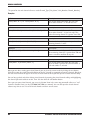
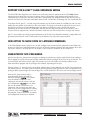
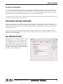
ADDENDUM
Lynx Software
Version 5.1
GSC3000 & VRC2500 Installation & Operation Manual
Lynx Software Version 5.1 Addendum (November 2005)
Copyright © 2005 Burk Technology, Inc. All rights reserved. No part of this manual may be reproduced in any form or by any
means without written permission from Burk Technology. Information in this manual is subject to change without notice.
Lynx 5.1 Features
The GSC3000 and VRC2500 Installation and Operation Manuals provide complete instructions for installing
and operating your transmitter remote control system with the Lynx 5 software. While the look and feel of Lynx
5.1 is very much the same as Lynx 5.0, there some important new features and enhancements covered here in
the Lynx 5.1 manual addendum. If you have any questions about the software or about the GSC3000 or
VRC2500 in general, please take a look at the support section of our web site at www.burk.com, or send email to
[email protected].
VIRTUAL CHANNELS
Beginning in Lynx 5.1, virtual channels provide a means within Custom Views to depict conditions based on
multiple input channels, alarm conditions and other virtual channels. They are a way to link a single on-screen
meter or status indicator to several different conditions. For example, a single virtual channel can give a true or
false reading to indicate whether either of two STLs is online. A map-based custom view can use virtual channels
to present indicators showing whether there are alarms at one or more sites. You can also use virtual channels to
compute new channel values based on mathematical expressions.
Since virtual channels are saved on the PC running Lynx, they are meant to be used primarily in the Custom
Views software environment and not in timed events or macros, which are stored in memory on-board the remote
control. However, the value for any virtual channel can be viewed by clicking the virtual channels toolbar icon.
The following is an overview for how to integrate virtual channels into your operation.
Creating A New Virtual Channel
To create a new virtual channel, open the virtual channels
utility by selecting Virtual Channels from the Tools menu.
When the utility opens, you will see a list of your existing
virtual channels, their definitions, and their current state.
Click New to define a new channel.
The text box with the blinking cursor is where you create
your virtual channel definition. The value of the virtual
channel is equal to the value of the expression in the text
box. Select channels (real or virtual) and/or alarm conditions
from the menu tree for use in the virtual channel. Then select
math functions from the menu tree or use the push-button
logic operators to determine how the virtual channel should
determine its value.
CUSTOMER SUPPORT: 978-486-3711 • [email protected] • www.burk.com
A3
MANUAL ADDENDUM
The syntax for site and channel references reads Channel_Type("Site_Name", Unit_Number, Channel_Number).
Examples:
Definition
Description
Status("Main", 0, 1) Or Status("Main", 0, 2)
The virtual channel will return the True state
when status channel 1, 2 or both are true.
Definition
Description
Status("Main", 0, 1) And Not Value("Main", 0, 2) > 150
The virtual channel will return the True state
when status channel 1 is true, but only if the
value of metering channel 2 is greater than 150.
Definition
Description
Value("Main", 0, 1) * Value("Main", 0, 2)
The virtual channel will return the product of
metering channels 1 and 2.
Definition
Description
Value("Main", 0, 2) > 150 And Not AnyAlarm()
The virtual channel will return the True state
when metering channel 2 is greater than 150 and
there is no alarm condition at any site.
Definition
Description
Alarm("Main", 4) Or Alarm ("Main", 5)
The virtual channel will return the True state
when an alarm is present on I/O unit number 4,
I/O unit number 5, or both.
When you are done creating your virtual channel, you can view the current result by clicking the test button.
Click OK to store the virtual channel definition on the PC. You will be prompted to name the channel. After that,
the new virtual channel will appear in the list of virtual channels when you first open the virtual channels utility.
You can later go back and edit or delete virtual channels by opening the virtual channels utility, and highlighting
the channel you want to delete or edit. Then click the delete or edit toolbar button.
Once you save your virtual channel, you can use it Custom Views in the same way you would reference a "real"
channel in Custom Views (see the GSC3000/VRC2500 user manual). You can also open the virtual channel
editor at any time to see a list of all virtual channels and their current states.
A4
GSC3000 & VRC2500 INSTALLATION & OPERATION MANUAL
MANUAL ADDENDUM
SUPPORT FOR G-LINK™ G-BUS EXPANSION SERIES
The G-Link™ G-Bus Expansion series allows users to directly interface equipment to the GSC3000 without
requiring discrete wiring for each input or output channel, and without using tradition wiring interfaces and
command relays. G-Link units connect to the G-Bus, so monitoring site conditions with G-Link does not use up
channels on an I/O unit. For more information about G-Link, visit the Burk Technology web site at www.burk.com.
To facilitate G-Link, Lynx 5.1 can now assign unit numbers via the G-Bus instead of via COM port. You can also
modify the unit number of an I/O unit in the same fashion. To change a unit number, right-click the unit icon in
the Site List and choose Set Unit Number. Note that during initial I/O unit setup, you will still connect
individually to each unit via the PC's COM port, and then use the Tools menu to set the unit number. This is
because units are shipped with a default unit number of 0, and each I/O unit must have a unique unit number.
Lynx 5.1 also provides the ability to upload firmware to the G-Link units. Detailed installation, configuration and
operation instructions for each G-Link product may be found in the respective product manuals.
NEW OPTION TO SHOW STATE OF LATCHING COMMANDS
In the Tools>Options menu, system users can now configure Lynx to show latched commands in bold. When this
option is checked, one command button in each pair of latching command channels will show whether the A or B
side of the channel is currently latched. This makes it easier to assess conditions at the remote site.
USER-SPECIFIC SITE PASSWORDS
Lynx 5.0 and Lynx 4.x governed user privileges according to individual user logins retained by the Lynx software..
A user logging in to Lynx with system privileges would have full unit privileges for all sites set up on that PC. This
is because Lynx connections used a single site password to access the remote unit and the software itself
determined which program and site privileges were allowed, depending on the user.
Starting in Lynx 5.1, a new level of security allows administrators to store multiple user-specific site passwords on
the remote I/O unit. This allows Lynx to continue governing program privileges while the I/O unit determines site
privileges. When Lynx privileges and site privileges are used in conjunction, the most restrictive privileges prevail.
User-specific site passwords may be
associated with System, Operator or
Observer privileges. System access allows
users to monitor all channels, issue
commands, run and edit macros, and edit
unit configuration. Operator access allows
the user to monitor all channels, issue
commands, and run macros but does not
allow access to unit configuration or editing
of macros. Users with Observer access can
only monitor channel conditions; all control
and configuration functions are disabled.
CUSTOMER SUPPORT: 978-486-3711 • [email protected] • www.burk.com
A5
MANUAL ADDENDUM
Once you have created a new site in Lynx, set up users and privileges by connecting to the site and right-clicking
the I/O unit icon representing the I/O unit the has the physical direct, modem or Web Interface connection.
Select the option for unit configuration, and when the configuration window opens, click the Users tab.
Note: User names entered under the Users tab are simply for the site administrator's reference; users never have to
type them in. The only place passwords are entered is in the Edit Site wizard.
Once individual site passwords are saved to the unit, disconnect from the site. Then click the edit site icon and
in the first page of the Edit Site wizard, change the site password to the user-specific site password you would
like used when anyone connects into this site. Only Lynx users with system-level privileges may change the
default password used for the site connection.
IMPORTANT! When first create the site in Lynx, you will specify a site password in the New Site Wizard. Be sure that it
is included in the password table (in the unit configuration Users tab) if you wish for users to gain access to the system
with that password.
If a user has system-level privileges associated with his Lynx login, but connects to a site that uses a user-specific
site password that only offers observer privileges, the more restrictive privilege level prevails. Similarly, a user
with observer privileges associated with his Lynx login who connects to a site that uses a user-specific password
with system privileges will not be able to issue commands because Lynx continues to restrict privileges according
to the Lynx user login.
NEW CUSTOM VIEWS TOOLS
Executing Applications via Custom Views
For any Custom Views component, the associated "Click Action" can be set up to run an application. Click on the
component in the Custom View Editor and select the Action tab. Choose "Run Application" as the desired
action, and then specify the name of the executable file for Windows to launch.
Invert Status Indication on Command-and-LED Component
On the Command-and-LED component, you can now select the "Invert This Channel" option to cause the LED
to illuminate when a Low/Off status is indicated. By default, the LED illuminates when a High/On status is
indicated.
Nominal Bar
The Nominal Bar is a new way to track metering channels by reference to an arrow that indicates the nominal (or
expected) value of the channel. Once set up, the bar that represents the meter will terminate at the nominal
arrow as long as the channel is at the nominal value. When the channel is out of tolerance, the arrow provides an
indication of where the value should be, allowing at-a-glance assessment of how much adjustment is needed.
When you set up the nominal bar, enter the lowest value that should be displayable on the meter in the
"minimum value" field and the normal or expected value in the "nominal" field. Select the low, normal and high
value ranges and color choices to determine when the meter changes color and which meter colors are
associated with each value range. The maximum value shown on the scale is always 25% higher than the nominal
value.
A6
GSC3000 & VRC2500 INSTALLATION & OPERATION MANUAL
MANUAL ADDENDUM
Text Files in Custom Views
The "Text File" Custom View control allows you to position a text box that is linked to a text file located on or
accessible from the local computer. You can edit the text file outside of Lynx, and the Custom View will display
the most current content whenever the view is loaded. This is useful for updating operator instructions, contact
telephone numbers, or any other message that you may need to periodically edit.
The properties tab for the text file component allows you to specify the file name of the desired text file, as well
as determine display settings for the text box.
NEW OPTION FOR USER PRIVILEGES
System level users can now prevent other users from closing Lynx or closing windows within Lynx. To prevent
others from closing Lynx, find the Tools > Options menu, navigate to the General tab, and click "Require privilege
to close Lynx." Then create a new user or edit an existing user with custom privileges, and leave unchecked the
privilege to close Lynx.
To prevent a user from closing the docking windows within Lynx, assign the user custom privileges and leave
unchecked the "Edit Docking Windows" option. The user will be able to resize and move windows, but will not be
able to close them completely.
SQL SERVER SUPPORT
By opening the Tools > Options menu and clicking
the SQL server tab, users can configure Lynx 5.1
to save logging data to a SQL server. Enter the
name/address of the server, the database name,
and restart Lynx after clicking OK to save your
settings. Find the lynx.sql file, saved in the Lynx
root folder, and forward it to the administrator of
the SQL server to complete setup.
CUSTOMER SUPPORT: 978-486-3711 • [email protected] • www.burk.com
A7
A8
GSC3000 & VRC2500 INSTALLATION & OPERATION MANUAL