1
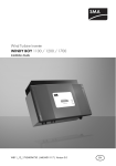
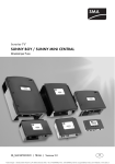
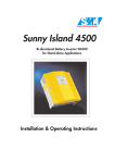
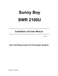
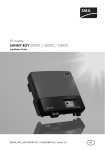
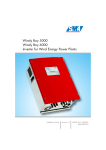
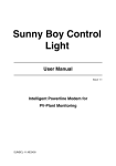
Sunny Boy 2500
Technical Description
Issue 1.1
String Inverters for Photovoltaic Plants
SB2500-11:EE4801
Sunny Boy 2500
SB2500-01:EE
Technical Description
-2-
SMA Regelsysteme GmbH
Sunny Boy 2500
Technical Description
Explanation of Symbols used in this Document
To enable optimal usage of this manual and safe operation of the device during installation, operation and maintenance routines, please note the following description
of symbols:
This indicates a feature that is important either for optimal and comfortable
usage or optimal operation of the system.
Example: “To keep string voltage low we recommend the following procedure.”
This indicates a fact or feature which is very important for the safety of the
user and / or which can cause a serious defect if not applied appropriately.
Example: ”Disconnect the mains plug before opening the case!“
This indicates an example.
SB2500-01:EE
-3-
SMA Regelsysteme GmbH
Sunny Boy 2500
Technical Description
Table of Contents
1
Introduction..........................................................................................................6
2
System Description..............................................................................................7
3
2.1
String Technology .......................................................................................8
2.2
Diagnosis and Communication .................................................................10
2.3
Technical design of the Sunny Boy 2500..................................................11
Installation .........................................................................................................16
3.1
What must be done in case of transport damages? .................................16
3.2
Placement of the Sunny Boy.....................................................................17
3.3
Electric Connection ...................................................................................22
3.3.1
Connection to the Electricity Grid .........................................................23
3.3.2
Connection of the PV-panels................................................................25
4
Commissioning ..................................................................................................27
5
Operation and Failure Indication LEDs..............................................................29
5.1
6
Opening and closing of the Sunny Boy .....................................................43
System Monitoring and Diagnosis .....................................................................47
6.1
Data Transmission via Powerline..............................................................47
6.2
Data Transmission with a Separate Data Cable .......................................49
6.3
Upgrading or modification of the Sunny Boy interface ..............................57
6.4
Graphic User Interface under Windows ....................................................60
6.5
Measuring Channels and Messages of the Sunny Boy ............................62
6.6
Measurement Precision ............................................................................65
7
Troubleshooting.................................................................................................66
8
Warranty Regulations and Liability ....................................................................68
9
Technical Data ..................................................................................................70
10
Appendix ...........................................................................................................78
SB2500-01:EE
-4-
SMA Regelsysteme GmbH
Sunny Boy 2500
Technical Description
Important Safety Notice:
The Sunny Boy String Inverter may only be opened by qualified personnel for both maintenance and modification.
The device can still be charged with very high hazardous voltages
even when disconnected.
For optimal safety closely follow all steps as described in the chapters 3, “Installation” and 5.1, “Opening and closing of the Sunny
Boy”.
SB2500-01:EE
-5-
SMA Regelsysteme GmbH
Sunny Boy 2500
Technical Description
1 Introduction
® 1
By purchasing a Sunny Boy
String Inverter you have decided to use one of the
most advanced devices for modular PV system technology. The Sunny Boy inverters
are the first systems that utilize the String Technology from SMA and convince with
their outstanding qualities concerning efficiency and reliability.
The Sunny Boys comply with all regulations from the VDEW (Association of German
Electricity Producers) for supplementary grid feeding to the low voltage electricity grid
of the utility. This includes the regulations of the employee association
(Berufsgenossenschaft für Feinmechanik und Elektrotechnik) concerning the “Independent Disconnection Device“ known as MSD (Mains monitoring device with allocated Switching Devices) and the regulations of the DIN VDE 0126. Furthermore the
Sunny Boy complies with the according harmonised standards and the low voltage
regulations as certified in the CE declaration (see appendix).
In the following you will find the technical description of the Sunny Boy 2500. Don’t
worry about its size, it is not necessary to read everything. This technical description
is both installer’s guide and user manual, so it is used as reference for the commissioning and as guideline on how to use all functions of the inverter optimally and how
you can extend your existing PV-plant.
1
Sunny Boy is a registered Trademark of SMA Regelsysteme GmbH
SB2500-01:EE
-6-
SMA Regelsysteme GmbH
Sunny Boy 2500
Technical Description
2 System Description
The need to reduce the CO² emission and other pollutants resulting from energy conversions is becoming more and more apparent. Renewable energy sources can
make an important contribution to solve this problem. The direct conversion of solar
radiation to electric energy (photovoltaics) will play a substantial role in this essential
matter world-wide.
Supplementary grid feeding includes the conversion of the DC voltage from the PVpanel to grid compatible AC voltage with so-called “inverters“ and the subsequent
connection to the electricity grid in the house distribution.
Here the electricity from the PV-modules provides all consumers with electric power
(household devices, lights etc.). In case that not enough energy is produced the additionally necessary energy is obtained from the grid. In case that there is a surplus of
energy, this surplus is fed into the local grid and is therefore available for other consumers. This way every single kilowatt-hour is utilized and the electricity company’s
power plants are relieved. In the most simple case a PV-plant therefore consists of
two basic components: the PV-panel and the inverter.
Fig. 2.1: Grid-tied PV plant
SB2500-01:EE
-7-
SMA Regelsysteme GmbH
Sunny Boy 2500
Technical Description
2.1 String Technology
The experience with several thousand grid-connected PV-systems in Europe with an
output range from one to several hundred kilowatts has shown that the costs for grid
connecting and monitoring the PV-system add up to almost 50 % of the costs for the
entire system. To reduce these costs, especially the costs for the cabling on the DC
side and the subsequent distribution on the AC side, and drastically simplify the design of PV-systems the string-technology was developed by SMA. The Sunny Boy
finally enabled this new, considerably simpler and better affordable String Technology to be the standard system design for PV-plants.
String Technology means that a small number of PV-modules are connected in series to a “string“, each string is then connected to a separate inverter which feeds the
electricity of one string to the grid. Large PV-plants consist of a large number of single strings. The energy produced is collected directly on the AC side, making the system design very simple. No extra DC cabling is necessary anymore.
The most various system concepts can be constructed with modules of the Sunny
Boy family.
•
Sunny Boy 700:
The small inverter for little PV-plants and simple extension
possibilities (3 input voltage and power ranges).
•
Sunny Boy 850:
The output optimized inverter for PV-plants with at least 1 kWp.
•
Sunny Boy 1100E:
For PV-plants with up to 1.5 kWp and equipped with a wider
input voltage range.
•
Sunny Boy 1700E:
For PV-plants around 2.2 kWp with a wide input voltage range.
SB2500-01:EE
-8-
SMA Regelsysteme GmbH
Sunny Boy 2500
•
Technical Description
Sunny Boy 2000:
The transformerless string inverter with extended input voltage range and increased efficiency.
•
Sunny Boy 2500:
The string inverter with electric separation and a broad input voltage range
(250 ~ 600 V).
•
Sunny Boy 3000:
The powerful string inverter with electric separation and optimum efficiency,
ideal for large-scale plants.
•
Sunny Display:
The optional integrated LCD display for direct data acquisition.
•
Sunny Data:
The PC-program for communication with your Sunny Boy inverters.
•
Sunny Boy Control Family:
The intelligent control terminals for your PV-plant for data acquisition, visualisation and saving.
•
Sunny Data Control:
The PC-program for visualization of data from your Sunny Boy Control.
SMA is the European market leader for inverters for photovoltaic applications with
over 100 MW of installed inverter power in over 60,000 single units with powers from
700 W up to 500 kW (11/01). The Sunny Boy is the result of a dedicated development resulting from the substantial experience with utility interactive inverters for
photovoltaics.
SB2500-01:EE
-9-
SMA Regelsysteme GmbH
Sunny Boy 2500
Technical Description
2.2 Diagnosis and Communication
The modular PV system technology leads to a spread out distribution of the Sunny Boy
String inverters. A simple and fast function monitoring of the status and measured values for each single Sunny Boy can be achieved with only a few system components.
The data collected is either displayed on the LCD of the Sunny Boy Control or is shown
on the screen of a PC running the according SMA software. Two programs “Sunny
Data“ and “Sunny Data Control“ are based on a comfortable Windows GUI and allow
the user to process the data with other programs such as MS Excel.
The signal transmission between the PC and the single inverters is normally done via
Powerline communication (see chapter 6.1). The Sunny Boy String Inverters support the
following monitoring concepts developed by SMA:
•
PC with Sunny Data for Windows for small and medium size PV-plants, also
with Sunny Boy Control.
•
Sunny Boy Control as stand-alone controller for any PV-plant size.
•
PC with Sunny Data Control for Windows together with a Sunny Boy Control.
Communication based on one of the above concepts supports the following functions:
•
Continuous acquisition of operation data of all connected Sunny Boys.
•
Supervision of operating states and failure indication.
•
Spot value transmission from one or several selected Sunny Boys.
•
Identification of failures in the single strings.
•
Graphical representation of the data from single Sunny Boys or comparison of
the data of several ones.
•
Modification of operation parameters to optimise the entire plant.
SB2500-01:EE
- 10 -
SMA Regelsysteme GmbH
Sunny Boy 2500
Technical Description
2.3 Technical design of the Sunny Boy 2500
The Sunny Boy inverter is based on a power unit that operates with a very high efficiency and optimal reliability. A IGBT bridge converts the direct voltage coming from
the PV modules to a high frequency AC secondary circuit with 16 kHz. The voltage is
then fed to the grid after being processed by a low-loss toroidal-core current trans-
L
Grid
Filter
-
Filter
+
+
+
Overoltage Protection
former.
N
R ISO
Board
supply
I AC
U PV
f AC
V AC
Current Control
(SRR)
Sequential Control
System (BFR)
MSD 2
MSD 1
Modem
(optional)
PE
Fig. 2.2: Block circuit diagram of the Sunny Boy 2500
The PV input voltage range of the Sunny Boy 2500 is designed for up to 24 standard
PV modules.
The current fed to the grid is perfectly sinus shaped and has a very low harmonic
distortion due to the fact that a one-chip computer manages the control. The sequential control system takes care of fully automatic operation and handles the MPPtracking (MPP = Maximum Power Point; fully automatic search for the PV output
voltage with highest output power). The sequential control system minimizes unnecessary losses in standby and in grid feeding mode.
The heat sink is necessary in order to let the energy resulting from the power semiconductor devices dissipate. The Sunny Boy 2500 is equipped with a temperature
monitoring system that detects too high a heat sink temperature (e. g. resulting from
SB2500-01:EE
- 11 -
SMA Regelsysteme GmbH
Sunny Boy 2500
Technical Description
high ambient temperature), reduces the power fed to grid and nevertheless keeps
feeding electricity to the grid.
The sequential control system also manages the communication with the corresponding SMA data analysis tools Sunny Display, Sunny Data and Sunny Data Control. The Sunny Boy therefore is not only a simple standalone device as it can be part
of one big PV-plant that has one central control and monitoring facility.
Two independent one-chip computers monitor the grid. This fully complies with the
according regulations of the VDEW and the employee associations. The grid monitoring is done by determining the grid impedance with a so-called MSD (Mains monitoring with allocated Switching Devices, German = ENS). This means the Sunny Boy
can be connected to the in-house network at practically every spot which substantially simplifies its installation. The relevant regulations and standards of course must
be kept to.
The case is made of stainless steel which protects the inverter from dust and water
up to IP 65. The Sunny Boy can therefore be mounted nearly anywhere inside or
outside the house with an ambient temperature range of –25 °C to +60 °C.
Personnel protection is a very important issue even with small PV-plants. The grid
and the PV-panels are electrically separated while the insulation is constantly monitored. All applicable standards and regulations for personnel safety and EMC are
complied with.
SB2500-01:EE
- 12 -
SMA Regelsysteme GmbH
Sunny Boy 2500
Technical Description
Disconnection from Grid (MSD)
This section covers the safe disconnection and shutdown of the inverters in case the
public electricity grid goes down. If the electricity supplier disconnects part of his
electricity grid e. g. to make repairs one has to make sure that nobody working on the
grid is harmed. In August 1994 a new safety concept was included into the VDEW
regulation initiated by the “Berufsgenossenschaft für Feinmechanik und Elektrotechnik“ (German Employee Association of Precision Mechanics and Electronics Engineering).
The Sunny Boy string inverter is designed only for utility interactive operation. To ensure safe shut-down in case of grid disconnection etc. and to avoid an “islanding
condition” the inverter is equipped with an independent disconnection device that has
been certified by the “Berufsgenossenschaft für Feinmechanik und Elektrotechnik“.
The regulation is called “Automatic disconnecting facility for photovoltaic
installations with a nominal output ≤ 4.6 kVA and a single phase parallel feed
by means of an inverter into the public low-voltage mains“.
For maximum safety this independent disconnection device consists of two separate
MSD (Mains monitoring with allocated Switching Devices) that are connected in series. Each of these MSD constantly monitors the grid quality by checking the frequency, voltage and impedance. The redundant circuit and an automatic self test on
each system startup ensure a reliable function of the disconnection.
Older islanding detection systems only evaluated the voltage of the 3 phase electricity grid. The new detection system additionally evaluates the grid impedance of the
feeding phase as well as the voltage and the frequency of the connected phase.
SB2500-01:EE
- 13 -
SMA Regelsysteme GmbH
Sunny Boy 2500
Technical Description
Conditions that cause the Sunny Boy to be disconnected from the grid:
•
Grid Impedance
−
The Sunny Boy does not start to feed to the grid if the grid impedance ZAC
is higher than 1.25 Ω.
−
The Sunny Boy is disconnected from the grid within 5 seconds once the
grid impedance increases drastically within a short time (∆ZAC ≥ 0.5 Ω) or
the impedance gets too high (ZAC ≥ 1.75 Ω).
•
Grid Voltage
−
The grid voltage may be within a range of -15 % and +10 % of the nominal
grid voltage UN. Once the grid voltage exceeds this range the Sunny Boy
is disconnected from the grid within 0.2 s.
•
Grid Frequency
−
The grid frequency may be within a range of ± 0.2 Hz of the nominal grid
frequency fN while the voltage is within a range of -30 % and +15% of the
nominal grid voltage Un - once the frequency goes beyond this range the
Sunny Boy is disconnected from the grid within 0.2 s.
−
Furthermore the Sunny Boy disconnects from the grid within 0.2 seconds
once the grid frequency changes drastically exceeding a certain range.
This new Sunny Boy disconnection concept provides maximum safety with minimum
installation effort due to the fact that the connection of the MSD must only be done to
one single phase.
SB2500-01:EE
- 14 -
SMA Regelsysteme GmbH
Sunny Boy 2500
Technical Description
The value of the grid impedance measured at the Sunny Boy is the total of the impedance of the public grid and the cabling impedance in the house (from house distribution to the Sunny Boy). Excessive increase of grid impedance through the connection cable to the inverter therefore has to be avoided.
Keep in mind that the cable between the Sunny Boy and the house distribution increases the impedance (see chapter 3.3.1,”Connection to the
Electricity Grid”).
The MSD regulations require a type verification and test by an independent certified
testing association. It is also required that the supplier of the inverter tests every single MSD before delivering the inverter to the customer. For the user this means:
•
The intensive testing of the disconnection device by the electricity company and
the installer and
•
periodic checking of the disconnection device, legally required previously, are
not necessary anymore.
The redundant design of the MSD and the regular self test on startup allow the user
to get along without periodic tests. Each startup includes a function test in order to
make sure that the allocated switching devices (transistor bridge and relay) are operating. The self test is repeated in case the test result was negative - if the failure persists the device must be checked by a qualified technician. The failure is indicated by
a warning LED meaning that the inverter is not feeding electricity to the grid. The system shutdown because of MSD malfunction cannot be reset with external signals in
order to ensure that the device is checked and set up for grid feeding only by qualified personnel.
SB2500-01:EE
- 15 -
SMA Regelsysteme GmbH
Sunny Boy 2500
Technical Description
3 Installation
The installation of the Sunny Boy string inverter must be done by
qualified personnel that is approved by the local electricity company.
Make sure that all instructions in this chapter are followed.
Follow all safety regulations and regulations of the local electricity
company.
3.1 What must be done in case of transport damages?
The inverters are thoroughly checked before they are shipped. Even though they are
delivered in a sturdy packaging (which can be recycled) the inverters can be damaged in transit, which is usually the forwarder’s fault.
Please inspect your inverter thoroughly after it is delivered. If any damages can be
detected on the packaging that could make you conclude the contents is damaged or
if you detect that the inverter is damaged please immediately notify the forwarding
company.
SMA or your local supplier can help you in this matter. In any case a declaration of
transport damage must be made within 6 days upon receipt of the product and must
be stated in writing directly to the forwarding agent. If it is necessary to return the
inverter to the manufacturer please use the packaging the inverter was sent in.
SB2500-01:EE
- 16 -
SMA Regelsysteme GmbH
Sunny Boy 2500
Technical Description
3.2 Placement of the Sunny Boy
The Sunny Boy is a complicated electronic device and is therefore sensitive to humidity within the case.
If the Sunny Boy is placed outside, the humidity during the installation
should be as low as possible - pay special attention that it does not rain. If
moisture is enclosed in the case it will eventually condense within the device which could damage the electronics.
A suitable position must be found for the inverter/s while the PV-plant is designed. To
find the optimum location please consider the following most important criteria.
Criteria for device mounting:
•
Due to the high protection class IP65 the installation is possible indoors and
outdoors.
•
If possible, do not expose the inverter to direct moisture despite IP65.
•
Keep the DC cabling from the solar generator to the inverter as short as possible.
•
Avoid installation in the living area because a slight noise emission is possible.
•
Avoid mounting on resonant parts (e. g. thin wooden panels, plaster panels,
etc.)
•
Provide accessibility for installation and later service.
•
Installation at level height makes it possible to easily view the operating LEDs.
SB2500-01:EE
- 17 -
SMA Regelsysteme GmbH
Sunny Boy 2500
Technical Description
Please note the following points in any case:
•
The mounting background must be firm.
•
The ambient temperature must lie between -25 °C and +60 °C.
•
Keep an eye on the grid impedance at the connection point (see
“Disconnection from grid (MSD)” and chapter 3.3.1, “Connection to
the Electricity Grid”).
•
Do not expose the string inverter to direct sunlight - this could reduce
the energy yield (if necessary install a sun shield).
•
A minimum distance of 200 mm must be clear above the inverter for
ventilation, i.e. no cupboards, ceiling, etc.
•
The free air circulation around the case must not be obstructed to
ensure sufficient cooling.
•
If you install the Sunny Boy in a cabinet or closet etc., the air circulation must be sufficient for heat dissipation - provide external ventilation.
•
The heat sink can reach a temperature of more than 80 oC.
•
Provide a correct position of the inverter see below:
mount inverter
straight or
tilted to back
Never
mount tilted
to front
Fig. 3.1: How to mount the inverter
SB2500-01:EE
- 18 -
SMA Regelsysteme GmbH
Sunny Boy 2500
Technical Description
Packing list for mounting and installation
The following components provide for safe and simple installation of the Sunny Boy and
are included in the packing list:
Sunny Boy 2500
Drilling template in appendix
1 pc.
AC-connection socket set
1 pc.
Seal for AC connection socket
1 pc.
Seal for MC plug
2 pc.
Seal for MC socket
2 pc.
Cable gland PG16
1 pc.
Tabelle 3.1: Packing list for mounting and installation
=
distance between the holes on the top 217.50 mm
+
=
63,50 mm
Drilling Template for the Sunny Boy 2000, 2500, 3000
+
top
position of the holes on the top
(for 6 mm screws)
mount the Sunny Boy
tilted to the back or
vertical!
Never mount the
Sunny Boy tilted
to the front!
Total height of the Sunny Boy: 295.50 mm
Please note:
vertical distance between the holes: 220.50 mm
Total width of the Sunny Boy: 434.50 mm
bottom hole
(6 mm diam.)
+
Fig. 3.2: Picture of drilling template - original template in appendix
SB2500-01:EE
- 19 -
SMA Regelsysteme GmbH
Sunny Boy 2500
Technical Description
Preparing the Mounting
The Sunny Boy is mounted on its back with 3 metal straps on a firm surface. 3
screws and the corresponding dowels are necessary. The screws and dowels are not
included and have to have a sufficient size. We recommend 6 mm screws and 8 mm
dowels.
For outside mounting use stainless steel screws. If necessary plastic
washers should be inserted between the screw and metal strap in
order to avoid scratching the paint when screwing.
Fig. 3.3: Side view of mounting to wall
Metal straps for mounting:
The top straps take the load, the bottom is screwed down in order to prevent tilting off the wall.
Securing the Sunny Boy against lifting up:
After the Sunny Boy has been hanged
into the top screws fasten the bottom
screw to secure against lifting up.
SB2500-01:EE
- 20 -
SMA Regelsysteme GmbH
Sunny Boy 2500
Technical Description
Mounting to wall
•
Mark the holes with the drilling template.
•
Drill the holes (and put in the dowels), put in the screws of both top holes and
screw them in until ca. 4 mm are sticking out.
•
Hang the inverter into the two top screws.
•
Fasten the bottom screw in order to prevent lifting up.
•
Check the mounting of the inverter.
SB2500-01:EE
- 21 -
SMA Regelsysteme GmbH
Sunny Boy 2500
Technical Description
3.3 Electric Connection
The electric connection of the Sunny Boy can be done once the device is correctly
mounted in its position.
The grid and the input from the PV-modules are connected to the inverter in the bottom of the case. The connection is done with special plug connectors (see Fig. 5.3).
The connection of the Sunny Boy to the DC voltage from the PV
string and the AC voltage of the utility must be done in the order described here. This ensures that the disconnecting of contacts as well
as hazardous voltages during the installation are avoided.
1. Connect to the electricity grid (see chapter 3.3.1)
2. Connect the PV string (see chapter 3.3.2)
3. Connect the PV string to the Sunny Boy
4. Connect the utility by putting the fuse on
Disconnecting the Sunny Boy must be done in the opposite order:
1. Disconnect the inverter from the grid (automatic circuit breaker “OFF”)
2. Disconnect the PV panel from the Sunny Boy (pull the MC plugs)
3. Remove the AC connector from the Sunny Boy
SB2500-01:EE
- 22 -
SMA Regelsysteme GmbH
Sunny Boy 2500
Technical Description
3.3.1 Connection to the Electricity Grid
The Sunny Boy must be connected to the grid with three cables - one phase, one
neutral and one protective earth (PE).
We recommend a 16 A automatic circuit breaker. No consumers are
allowed on this circuit or they have to be fused separately.
The grid impedance value at the connection point must be lower than 1.0 Ω in any
case in order to fulfill the necessary conditions for the MSD (see chapter “Mains
monitoring with allocated switching devices”).
The impedance is the sum of the electricity grid impedance at house distribution and all impedance values of cables and clamping points.
NB: Impedance values are
- ca. 0.48 Ω for a 20 m cable with a cross section of 1.5 mm²
- ca. 0.50 Ω for a 35 m cable with a cross section of 2.5 mm²
The AC connector socket for utility connection can take a cross section of
up to 2.5 mm².
Make sure the grid is disconnected in the fusebox before you connect the AC connection socket.
The AC connector is a round socket that is suitable to take different cable diameters.
A PG13.5 and a PG16 cable seal are included with the AC connection socket. Check
which size is suitable for your AC connection cable.
Strip the insulation off the ends of the cable and connect the cable to the AC socket
as shown in Fig. 3.4 “AC connection socket”.
SB2500-01:EE
- 23 -
SMA Regelsysteme GmbH
Sunny Boy 2500
Technical Description
Cable seal PG16
Cable seal PG13.5
Fastening case
for PG13.5
Socket tube
Socket
Rubber ring
for PG13.5
Threaded ring
Fig. 3.4: AC connection socket
•
Push the rubber ring into the fastening case.
•
Put the cable through the PG 13.5 or 16 cable seal. Put the cable through the
fastening case with the rubber ring and through the socket tube.
•
Connect the wires of the AC cable as follows:
−
Protective Earth (PE) to the terminal with the “ground” symbol
−
Neutral wire to the terminal marked with “1”
−
Phase L to the terminal marked with “2”
−
The terminal marked with “3” is not used.
•
Make sure that all wires are firmly connected.
•
Push the socket tube firmly onto the socket.
•
Screw the cable seal firmly onto the socket tube.
•
For cables that require the PG16 gland: Tighten the bolt of the PG16 gland.
•
The AC connector socket is now ready to use.
•
Seal the AC connector socket in case you do not insert it into the Sunny Boy.
SB2500-01:EE
- 24 -
SMA Regelsysteme GmbH
Sunny Boy 2500
•
Technical Description
The AC connector socket can be inserted into the Sunny Boy in case the Sunny
Boy is already mounted in the correct position. Remove the transparent seal
from the AC connector on the Sunny Boy, insert the AC connector plug and
tighten the seal.
3.3.2 Connection of the PV-panels
Safety Notice
The inverter system is electrically separated in order to provide maximum protection
against dangerous touch voltage in the PV-plant. This means that neither the + nor
the – cable are electrically connected to the PE, i.e. there is normally no dangerous
voltage between the PE and the + or - pole.
The Sunny Boy constantly monitors the electrical resistance of the + and - poles to
PE. The red LED is switched on whenever resistance is below 1 MΩ (see chapter 5,
“Operation and Failure Indication LEDs“) .
The voltage between the + and - pole of the PV-modules (string voltage) can be lethal!
The circuit that monitors the insulation results in a slight electric connection to the
PE. The very high resistance of the circuit normally prevents a dangerous current
from flowing through the human body. However, high resistance voltage meters will
indicate voltage between the case of the string inverter and the plus and/or minus
poles.
Never disconnect the PV-modules from the Sunny Boy (by pulling
the Multicontact snap cable connectors) before disconnecting the
grid, i. e. never during feeding operation of the Sunny Boy! Always
disconnect the Sunny Boy from the grid first - the Sunny Boy will
then stop feeding to the grid and the Multicontact connectors are not
under load anymore.
SB2500-01:EE
- 25 -
SMA Regelsysteme GmbH
Sunny Boy 2500
Technical Description
Connection to the PV-modules
In order to simplify safe mounting and servicing the Sunny Boy is connected to the
PV-modules with safe to touch snap cable connectors type Multi-Contact which were
especially designed for PV applications.
Make sure that the + and – snap cable connectors of the PV-modules
are connected to the right poles of the PV module voltage.
Depending on the type of PV-module used it is possible to connect one single string
or two or three parallel strings. Therefore there are three connections for both the +
and the – pole. Within the device these connections are connected in parallel each.
Should you be working with one single string connection please
close the snap cable connectors on the Sunny Boy that are not used
by the seals provided with the delivery.
Before connecting the snap cable connectors of the PV-panel to the
Sunny Boy check the correct polarity and admissible PV-panel voltage between the + and the – snap cable connector of the PV-panel.
The PV-panel voltage must be below or at most equal 600 V DC
(UPV ≤ 600 V DC).
The PV-panel is connected to the Sunny Boy with the MultiContact connectors on the
left-hand side at the bottom of the case.
SB2500-01:EE
- 26 -
SMA Regelsysteme GmbH
Sunny Boy 2500
Technical Description
4 Commissioning
Safety notice
Check that no tools, wires or similar equipment are placed on the case of
the Sunny Boy 2500 during operation.
On top of the device you can find the heat sink of the Sunny Boy with potential temperatures of over 80 °C. Danger of burning.
First switching on
If the correct polarity and an admissible level of PV-panel voltage have been confirmed in the measurement (see chapter 3.3.2) remove the seals from the snap cable
connectors at each end of the PV-panel cable.
•
Mount these to the Sunny Boy until they have full contact. As soon as the PV®
panel has been connected via the Multi-Contact plug connectors, internal
PV-panel voltage is on.
•
Connect the grid voltage by closing the circuit breaker of the supply lead.
If the input voltage is high enough the Sunny Boy should start to feed inverted PV
power fully automatically to the grid, once enough power is coming from the PVmodules.
The design of the Sunny Boy makes sure that its internal consumption is as low as
possible. The Sunny Boy requires a maximum 7 W internal consumption which it
takes from the PV-panel.
If you measure the voltage coming from the PV-modules you must keep in mind the
inverter’s internal consumption that will have an effect on your measurement with
lower solar radiation. The open circuit voltage of the PV-panel will therefore not be
SB2500-01:EE
- 27 -
SMA Regelsysteme GmbH
Sunny Boy 2500
Technical Description
displayed. The internal consumption is negligible for the voltage measurement with
higher solar radiation.
The operating state of the Sunny Boy will be indicated with three LEDs integrated
into the lid. The meaning of the LEDs will be explained in chapter 5, “Operation and
Failure Indication LEDs”.
SB2500-01:EE
- 28 -
SMA Regelsysteme GmbH
Sunny Boy 2500
Technical Description
5 Operation and Failure Indication LEDs
General
The inverter normally operates automatically, without user interaction and without
any maintenance. The inverter automatically turns itself off when a grid feeding is not
possible (e. g. at night).
The Sunny Boy automatically starts its grid feeding the next day once the solar radiation is high enough. The inverter goes to standby mode if the radiation and the resulting electric input energy is too low and is therefore always ready for operation.
Each time the Sunny Boy starts up it runs a number of self tests and safety procedures.
The green LED “Operation“ indicates the current operation.
The red LED warns the user that an “Earth Fault“ has occurred. A description of this
situation and what has to be done in that case is given in the section "Earth Fault
Indicator".
The yellow LED “Failure“ indicates an internal or external failure that keeps the inverter from feeding the grid. The specific causes for this and how to avoid them are
described in detail in section "Failure Indication”.
SB2500-01:EE
- 29 -
SMA Regelsysteme GmbH
Sunny Boy 2500
Technical Description
Betrieb
Operation
Erdschluss
Earth Fault
SWR 2500
Photovoltaik-Stringwechselrichter
Photovoltaic string inverter
Störung
Failure
Fig. 5.1: Front view of part of the Sunny Boy
Description of the symbols used in the following section:
SB2500-01:EE
- 30 -
SMA Regelsysteme GmbH
Sunny Boy 2500
LED indicator
Technical Description
Operating Condition
Description
standby (night)
input voltage < 85 V
initialization
input voltage 85 V – 225 V
stop
changing operating condition or manually
initiated condition
green:
waiting,
starting conditions are being checked
red:
checking grid
green:
red:
yellow:
green:
red:
yellow:
green:
red:
yellow:
yellow:
green:
feeding grid
red:
MPP or constant voltage mode
normal operation
yellow:
green:
derating
Reduction of power fed to the grid due to
increased heat sink temperature
isolation failure
earth fault of the PV-panels or failure of
surge voltage protection
failure
internal or external failure, exact description depending on blink code
permanent device disable
failure of MSD
red:
yellow:
green:
red:
yellow:
green:
red:
yellow:
green:
red:
yellow:
Table 5.1: Sunny Boy operation indication overview
SB2500-01:EE
- 31 -
SMA Regelsysteme GmbH
Sunny Boy 2500
Technical Description
Operation Indicator
Standby (night)
All LEDs are off.
The Sunny Boy is in “standby (night)“ mode. The input voltage is too low
(UPV< approx. 85 V) to supply the Sunny Boy control system with enough power.
Initialization
All LEDs are on.
The Sunny Boy control system is initializing.
The string voltage to the inverter is between approx. 85 V and 225 V. The supply is
sufficient for the system control and not quite sufficient for feeding to the grid. Data
transmission is not possible yet.
SB2500-01:EE
- 32 -
SMA Regelsysteme GmbH
Sunny Boy 2500
Technical Description
Stop
Green LED blinking (approx. three times per second)
Red LED off
Yellow LED off
The inverter has stopped operation, among other things the measurement electronics is calibrated. Subsequent condition is “Waiting“.
“Stop“ condition can be initiated by the user with the Sunny Boy Control or the program Sunny Data. The Sunny Boy remains in this condition until set to “MPPOperation“ or “Constant Voltage Operation“ or until reinitialized (e. g. after system
shutdown).
Waiting, Grid Monitoring
Green LED blinking once per second
Red LED off
Yellow LED off
The Sunny Boy is checking the grid concerning its suitability for feeding electricity
(starting voltage, starting time) and begins to monitor the grid.
SB2500-01:EE
- 33 -
SMA Regelsysteme GmbH
Sunny Boy 2500
Technical Description
Operation
Green LED on
Red LED off
Yellow LED off
The Sunny Boy has successfully completed self-testing electronics and the MSD and
starts feeding to the grid.
•
“MPP“-mode (default setting):
The Sunny Boy independently acquires the MPP voltage of the PV panel which
is internally defined as PV setpoint voltage. In MPP mode the maximum power
point PAC is set by changing the required PV voltage at the PV-panel.
•
“Constant Voltage“-mode
The voltage from the PV-modules can be set to a fixed value. This value (“UKonst”) can be manually defined by the operator and transmitted to the Sunny
Boy via the Sunny Boy Control or with the Sunny Data software. In the constant
voltage mode the Sunny Boy uses a strictly defined PV voltage setpoint.
SB2500-01:EE
- 34 -
SMA Regelsysteme GmbH
Sunny Boy 2500
Technical Description
Earth Fault Indicator
Insulation failure, defective varistor
Red LED on
The Sunny Boy indicates an earth failure with the red LED. This condition can occur
together with other indications.
The indication of “Earth Fault“ can result from two different reasons: Either the PVpanels connection has an isolation failure or one of the two or both thermally monitored varistors on the DC side have developed a high resistance and therefore do not
let any current pass.
The possible failures are described in the following together with the methods to find
out how to distinguish the reasons for the failure.
•
Insulation failure
Failure at the PV-panel or PV connection. The plus or minus pole from the PVpanel or one of the PV-modules has a connection (< 1 MΩ) to the grounding
earth, PE.
The repair of an insulation failure must be conducted by qualified personnel.
A low resistance connection between the plus or minus pole and the grounding,
displayed as an isolation failure, results in the possibility of highly dangerous
electric shocks while only touching one pole. That means that the user is in
danger when touching one pole since the user himself normally is connected
with the ground.
SB2500-01:EE
- 35 -
SMA Regelsysteme GmbH
Sunny Boy 2500
•
Technical Description
Failure of the thermally monitored varistors
On its DC input side the Sunny Boy is equipped with thermally monitored varistors (plus and minus pole to protective earth each). They are installed in order
to prevent the inverter from being destroyed by atmospheric surge voltages
(electric fields from thunderstorms etc.). A thermally monitored varistor is the
serial circuit of a varistor and a thermal fuse. If the thermally monitored varistors
have triggered for several times they can lose their effect by not letting any current pass anymore and therefore not provide the intended safety anymore. This
condition is indicated with the “Erdschluß / Earth Fault“ LED.
The replacement of a thermally monitored varistor should be
conducted by qualified personnel.
•
Determining the Failure
The red LED indicates one of the above mentioned failures. A short description
on how qualified personnel can distinguish between these and conduct the appropriate countermeasures is given in the following.
Please take note of all relevant information in chapter 3.3, “Electric Connection”
and 5.1, “Opening and closing of the Sunny Boy”.
−
Open the Sunny Boy according to the description in chapter 5.1.
−
Remove the two internal thermally monitored varistors (see Fig. 5.3
“Interior of the Sunny Boy 2500”) with a screwdriver.
•
−
Connect the connectors 2 and 3 of the terminal strip on the main board.
−
Connect the PV-panel by the MC plug connector
−
Connect the grid voltage
If the red LED is off see “A“ - if the LED is on see “B“.
SB2500-01:EE
- 36 -
SMA Regelsysteme GmbH
Sunny Boy 2500
A
Technical Description
The red LED is off. At least one of the thermally monitored varistors is defective. Replace both varistors - they are only available from the manufacturer because they are designed especially for the Sunny Boy.
The thermally monitored varistors are not available on the market but are
especially designed for use in the Sunny Boy.
B
The red LED is still on. The following must be done:
•
Disconnect the inverter from the grid.
•
Disconnect all poles of the inverter from the PV-panels by pulling the MultiContact plug connectors.
•
Wait 5 minutes until the internal voltage has discharged.
•
Remove the bridges from 2 to 3 in the two connector blocks. Mount a bridge
from connector 2 in one connector block to connector 2 in the other connector
block.
•
Re-connect the PV-panels and the grid to the Sunny Boy.
If the red LED is still on, the Sunny Boy is damaged and must be repaired by
the manufacturer.
If the red LED is off the isolation of the Sunny Boy or the connection cabling is defective.
•
Disconnect the Sunny Boy from the grid.
•
Disconnect the PV-panel from the inverter by MC plug connectors.
•
Now the isolation fault should be found and removed by taking appropriate
measurements.
•
Close the Sunny Boy as described in chapter 5.1.
SB2500-01:EE
- 37 -
SMA Regelsysteme GmbH
Sunny Boy 2500
Technical Description
Failure Indication
Consistent Failure
Operation
Earth Fault
Failure
The yellow failure LED is permanently on.
This is a failure of the grid monitoring or the autonomous disconnection device MSD.
The Sunny Boy has detected a failure in the autonomous disconnection facilities and
has suppressed the grid feeding. Further proceedings are described in chapter 7.
SB2500-01:EE
- 38 -
SMA Regelsysteme GmbH
Sunny Boy 2500
Technical Description
Blinking code 2: Grid Failure
The yellow failure indication LED is activated for 5 seconds, is out for 3 seconds and
then blinks twice. The code is sent three times.
If the failure consists the indication blinking code is repeated.
The Sunny Boy is indicating a failure which has one of the following reasons:
•
Low grid voltage ( < VAC min see Table 9.1)
•
High grid voltage ( > VAC max see Table 9.1)
•
Low grid frequency (< fAC min see Table 9.1)
•
High grid frequency ( > fAC max see Table 9.1)
•
Drastic change of frequency ( > |dFAC | see Table 9.1)
Check the electric grid supply (check the function of other electric consumers) and
check the fuse of the mains connector to the Sunny Boy.
If you do not find any failure have the grid connection to the Sunny Boy
checked by a qualified electrician. Check the correct connection and the
fuse in the Sunny Boy (see Fig. 5.3: Interior of the ).
Do not forget to disconnect the Sunny Boy before opening the device. Follow the instructions for opening and closing of the Sunny Boy given in
chapter 5.1.
SB2500-01:EE
- 39 -
SMA Regelsysteme GmbH
Sunny Boy 2500
Technical Description
Blinking Code 3: Grid impedance too high
The yellow failure LED is activated for 5 seconds, remains dark for 3 seconds and
then blinks three times. The code is sent three times.
If the failure consists the indication begins once again.
The Sunny Boy has detected a failure based on non-permissible grid impedance values. The criteria for the grid impedance are described in the section “MSD“.
A too high grid impedance can be the reason in case this failure occurs very often,
forcing the inverter to switch off. The impedance can be checked with the Sunny Boy
Control or Sunny Data. Should the impedance be ZAC ≥ 1,25 Ω the Sunny Boy may
not connect to the grid. This failure can normally be avoided by increasing the cross
section of the AC cable connected to the inverter.
SB2500-01:EE
- 40 -
SMA Regelsysteme GmbH
Sunny Boy 2500
Technical Description
Blinking code 4: Input voltage (PV-panel) too high
The yellow failure indication LED is activated for 5 seconds, is out for 3 seconds and
then blinks four times. The code is sent three times.
If the failure consists the indication is repeated.
The input voltage is too high. The PV-panels are generating a voltage higher than the
permissible specified voltage!
Disconnect the grid and then the PV-panels from the Sunny Boy immediately. Too high input voltages can cause a non-repairable damage.
Have the circuits of your PV-panels checked by your electrician. The permissible PV
input voltage of the Sunny Boy is listed in the technical data in chapter 9.
SB2500-01:EE
- 41 -
SMA Regelsysteme GmbH
Sunny Boy 2500
Technical Description
Blinking code 5: Device failure
The yellow failure indication LED is activated for 5 seconds, is out for 3 seconds and
then blinks five times. The code is sent three times.
If the failure consists the indication is repeated.
The Sunny Boy is in a condition that makes it impossible to return to normal operation and is most likely defect.
The Sunny Boy has to be checked by a qualified technician.
SB2500-01:EE
- 42 -
SMA Regelsysteme GmbH
Sunny Boy 2500
Technical Description
5.1 Opening and closing of the Sunny Boy
Normally the Sunny Boy operates fully automatically and maintenance-free. Should
the device nonetheless be opened e.g. for
•
upgrading or modification of the Sunny Boy interface
•
control of internal fuse
•
analysis of earth fault indication
follow the instructions given below.
Opening of the Sunny Boy
The Sunny Boy must only be opened by a qualified electrician.
When working on the Sunny Boy follow the instructions below:
1. Separate the Sunny Boy from the grid by opening the circuit breaker.
2. Separate all poles of the Sunny Boy from the PV-panel by pulling the MC plug
connectors.
Wait for approx. 5 minutes until internal voltage has discharged.
3. Open the Sunny Boy in the following order.
4. Take off the lid by removing screws 1-4 (see Fig. 5.2 on page 44) on the lid (M5).
SB2500-01:EE
- 43 -
SMA Regelsysteme GmbH
Sunny Boy 2500
Technical Description
2
1
Betrieb
Operation
SWR 2500
Photovoltaik-Stringwechselrichter
Photovoltaic string inverter
Erdschluss
Earth Fault
Störung
Failure
4
3
Fig. 5.2: Front view of the Sunny Boy 2500
On the inside of the lid there is a tab connector contact with a greenyellow grounding cable (PE connection). Carefully separate this cable.
You now have the opened Sunny Boy in front of you and can see the position of
components and clamps relevant for you. You will find:
•
The internal fuse
•
The thermally monitored varistors
•
The control system board with the socket for the piggy back board for the communication
SB2500-01:EE
- 44 -
SMA Regelsysteme GmbH
Sunny Boy 2500
Technical Description
Thermally monitored
varistors
Piggy Back
for communication
Program memory
Grid fuse
(15 A, slow blow)
1
2
3
3
SMA
SWR-SRR
VX.xx
2
SMA
SWR-BFR
VX.xx
1
ENS1
150 V
200 V
ENS2
+++
+
+
---
+
-
DC connection
Multi-Contact
-
Opening for
communication cable
AC connector
Fig. 5.3: Interior of the Sunny Boy 2500
SB2500-01:EE
- 45 -
SMA Regelsysteme GmbH
Sunny Boy 2500
Technical Description
Closing of the Sunny Boy
1. Restore the PE connection of the lid with the tab connector of the green-yellow
PE conductor. When putting the lid on make sure the seal in the inner side of the
lid is placed correctly. When screwing the inner screws make sure that the thread
in the Sunny Boy case is not damaged by tilted screws. Under certain conditions
the protection class IP65 cannot be guaranteed any more. When mounting the
Sunny Boy outside moisture can get into the device and damage the electronics.
2. Connect the PV-panel by plugging on the MC plug connectors
(see also chapter 3.3.2).
3. Connect the grid.
With sufficient power from the PV-panel the Sunny Boy should now start automatically feeding the grid.
SB2500-01:EE
- 46 -
SMA Regelsysteme GmbH
Sunny Boy 2500
Technical Description
6 System Monitoring and Diagnosis
6.1 Data Transmission via Powerline
Signal transmission between the Sunny Boy and the Sunny Boy Control or the PC is
done with the grid connection via Powerline. This requires a minimum of installation
(see below). The Sunny Boy must be equipped with a Powerline modem for data
transmission. The PC must be equipped with the socket modem (SWR-COM). This is
already integrated in the Sunny Boy Control, the specific controller for PV-plants. The
PC or the Sunny Boy Control can be positioned anywhere within the in-house network as they acquire data directly from the AC circuit.
For trouble-free operation the Sunny Boys and the PC socket modem or the Sunny
Boy Control must be connected to the same phase of the in-house network. If the
communicating partners are connected to different phases the communication must
be established with a so-called phase coupling device. The phase coupling device is
available from SMA and must be installed by qualified personnel. It will make communication within the entire in-house network possible.
Sunny Boy
Sunny Boy
Sunny Boy
Powerline
Sunny Boy
Control
Sunny Boy Sunny Boy
Sunny Boy
Powerline
SWR-COM
Sunny Boy
Sunny Boy
PC
Sunny Boy
RS232,
modem
Powerline
Sunny Boy
Control
PC
Fig. 6.1: Example of data transmission via Powerline
SB2500-01:EE
- 47 -
SMA Regelsysteme GmbH
Sunny Boy 2500
Technical Description
What do you need for Powerline communication?
l
The Sunny Boy must be suitable for Powerline communication (order no.:
SWRxxxx-NE:1x0). I. e.:
−
The Powerline piggy back modem is installed (see Fig. 6.3: System control
board Sunny Boy with RS232 cabling).
−
The blue resistors under the piggy back have to be installed for Powerline
communication (see Fig. 6.3).
l
For communication with the PC
−
A socket modem SWR-COM is available.
−
Some PCs are equipped with a 25-pole COM interface. Then a small
adapter is necessary (order no. 39-5010).
−
The visualisation software Sunny Data must be installed.
How to install Powerline Communication
•
Powerline Communication with a PC
The RS232 connector from the SWR-COM is plugged into a free COM port of
the PC. The SWR-COM is plugged into the electricity socket. For details on the
visualisation software Sunny Data please see the Sunny Data manual.
•
Powerline Communication with a Sunny Boy Control
Plug the 230V power cable of the Sunny Boy Control into the electricity socket.
For operation of the Sunny Boy Control and the usage of Sunny Data Control
for Sunny Boy Control refer to the according manuals.
SB2500-01:EE
- 48 -
SMA Regelsysteme GmbH
Sunny Boy 2500
Technical Description
6.2 Data Transmission with a Separate Data Cable
RS232 communication is only suitable for data transmission between a
PC and one single Sunny Boy.
Data transmission via Powerline is a reliable and affordable solution. In electrical
grids which are strongly influenced by high-frequency disturbance such as those in
industrial sites data transmission via Powerline may not be possible. Communication
between the Sunny Boys and the Sunny Boy Control or the PC can then be done
with a separate data cable.
RS232 communication
If only one Sunny Boy has to be connected to the PC the easiest way is direct coupling via an RS232 port. A maximum of 15 m is permissible between the PC and the
Sunny Boy.
Single
Sunny Boy
RS 232
Electricity Grid
PC
Fig. 6.2: Example for RS232 communication with a single Sunny Boy
RS232 communication with a Sunny Boy is only a reasonable solution
with direct connection to the PC.
If a Sunny Boy Control is used instead of the PC an RS485 connection is
necessary. See section “RS485 communication” for details.
SB2500-01:EE
- 49 -
SMA Regelsysteme GmbH
Sunny Boy 2500
Technical Description
What do you need for RS232 communication:
•
A special RS232 Piggy-Back module and an appropriate cable gland for the
Sunny Boy
•
The visualization software Sunny Data is installed on the PC
•
The light blue resistors (Fig. 6.3) on the system control board are removed.
•
Some PCs are equipped with a 25 pin COM port. In this case a small adapter is
necessary (order no. 39-5010).
Installation
•
Please read chapter 6.3 carefully.
•
Connect RS232 connection cable LIYCY; 0.25 mm2, minimum three-cable with
common shield and a maximum length of 15 m. You can see the connector layout in Fig. 6.3. The shielding should be connected to protective earth (PE) on
both ends at the Sunny Boy and the PC case.
SB2500-01:EE
- 50 -
SMA Regelsysteme GmbH
Sunny Boy 2500
Technical Description
232 PB - G3
Piggy-Back
socket
3
2
1
Jumpers
(not mounted)
Shield
light blue resistors
(removed)
connect shield
to case
GND
TXD
RXD
DB9 socket
Shield
PC with DB9
plug in
COM1 .. COM4
PC
RXD
TXD
DB25 socket
GND
or
PC with DB25
plug in
COM1 .. COM4
PC
Fig. 6.3: System control board Sunny Boy with RS232 cabling
SB2500-01:EE
- 51 -
SMA Regelsysteme GmbH
Sunny Boy 2500
Technical Description
RS485 communication
In grids loaded with high interference several Sunny Boys can be connected to a PC
or the Sunny Boy Control via RS485 and a separate data cable. Data cables of up to
1200 m are permissible.
Sunny Boy Sunny Boy
Sunny Boy
Sunny Boy Control
RS485
Sunny Boy Sunny Boy
interface
converter
Sunny Boy
RS232
RS485
PC
Fig. 6.4: Schematic layout of RS485 data transmission with several Sunny Boys
Fig. 6.5: Cross section of the recommended RS485 cable
SB2500-01:EE
- 52 -
SMA Regelsysteme GmbH
Sunny Boy 2500
Technical Description
What do you need for RS485 communication:
•
A special RS485 Piggy-Back module and appropriate cable glands for all Sunny
Boys
•
The light blue resistors (Fig. 6.6) on the system control board are removed.
•
If connected to a PC:
The interface converter RSU485 (ordering no. 39-0020) is available.
Sunny Data visualization software is installed on the PC.
Some PCs have a 25-pole COM port. In this case a small adapter (ordering no.
39-5010) may be necessary.
SB2500-01:EE
- 53 -
SMA Regelsysteme GmbH
Sunny Boy 2500
Technical Description
PC
with DB 25 Plug-in
COM1 or COM2
Sunny Boy Control
(Socket “Sunny Boy 485”)
or
RS485 / RS232
Interface converter
SUB-D 9 pin to SUB-D 25 pin
No. 39-0020
Sunny Boy Control: Plug-in DB9
PC with interface converter: Socket DB9
680
5
9
8
7
6
3
680
connect shield
to case (PE)
485G3
Resistors
under the PiggyBack module must
be removed
Jumpers
not mounted
3
2
1
rst
1 Sunny Boy
MOSR15-SP
MOSR15-SP
Resistors
under the PiggyBack module must
be removed
Jumpers
not mounted
3
2
1
2nd Sunny Boy
485G3
connect shield
to case (PE)
Up to 50 Sunny Boys
MOSR15-SP
connect shield
to case (PE)
485G3
Resistors
under the PiggyBack module must
be removed
Jumper 1
mounted
3
2
1
last Sunny Boy
Fig. 6.6: System control board Sunny Boy with RS485 cabling
SB2500-01:EE
- 54 -
SMA Regelsysteme GmbH
Sunny Boy 2500
Technical Description
Installation (RS485)
•
Read chapter 6.3.
•
Connect pin 7 and pin 9 on the end of the cable that is connected to the interface
converter.
•
If you are using a PC instead of a Sunny Boy Control, switch the interface converter RS485/RS232 (ordering no. 39-0020) to “DTE“.
•
The transmission cable is terminated on the last Sunny Boy on the cable. There a
termination resistor is connected by mounting a jumper (no. 1, jumper directly
above the terminal strip).
•
Two resistors of 680 Ohm each must be integrated into the DB9 connection at the
beginning of the cable that is connected to the Sunny Boy Control or the PC. One
is soldered from pin 3 to pin 6, the other is soldered from pin 5 to pin 8 (see Fig.
6.6). These resistors are not required for communication with the Sunny Boy Control if the corresponding jumpers were plugged on.
•
The recommended cable for the RS485 connection is a LIYCY 2 x 0.25 mm
twisted pair cable. It consists of four data lines of which two are each combined
to altogether two twisted pairs. Both pairs are surrounded by a single common
shield. Maximum length of the entire RS485 connection is 1200 m (4000 ft.). It
is essential to connect the outer shielding to protective earth (PE) on both ends.
•
If necessary an adapter for the RS232 plug from the interface converter to the PC
(9-pin to 25-pin)
SB2500-01:EE
- 55 -
SMA Regelsysteme GmbH
Sunny Boy 2500
Technical Description
9-pin to 25-pin adapter
DB9
DB25
Description
1
8
DCD (Data Carrier Detect)
2
3
RX (Receive Data)
3
2
TX (Transmit Data)
4
20
DTR (Data Terminal Ready)
5
7
GND (Signal Ground)
6
6
DSR (Data Set Ready)
7
4
RTS (Request To Send)
8
5
CTS (Clear To Send)
9
22
RI (Ring Indicator)
Table 6.1: Pin designation of the DB9/DB25 adapter
SB2500-01:EE
- 56 -
SMA Regelsysteme GmbH
Sunny Boy 2500
Technical Description
6.3 Upgrading or modification of the Sunny Boy interface
The Sunny Boy is prepared for data transmission. By simply plugging on a piggy
back module it supports the RS232 or RS485 interfaces for the Powerline protocol.
In order to install a new interface in the Sunny Boy a corresponding piggy back module has to be installed on the system control board. Please follow all relevant instructions in chapters 3.3, “Electric Connection”, 4, “Commissioning”, 5.1, “Opening and
closing of the Sunny Boy” in the Sunny Boy manual.
The Sunny Boy works with high voltages externally and internally
which can cause considerable harm to people. Only a qualified electrician may work on the device, especially open it!
While upgrading the Sunny Boy interface the operator can get into touch both with
electronic components and components carrying lethal voltage. Faulty upgrading can
lead to damage at the device and danger to people by electric voltage.
Therefore the device may only be upgraded by qualified personnel or the SMA service.
Only work on the Sunny Boy when it is disconnected from the grid
and sufficiently discharged!
SB2500-01:EE
- 57 -
SMA Regelsysteme GmbH
Sunny Boy 2500
Technical Description
Follow ESD protection countermeasures when modifying the Sunny Boy:
Electronic components are sensitive to electrostatic discharge. To protect them you
have to be on the same electric potential. Discharge the electrostatic charge by
touching the grounded case before touching an electronic component, otherwise you
take a great risk in destroying your electronics.
Open the device as described in chapter 5.1.
Remove the piggy back that is installed on the system control board.
•
Only for installation of an RS232 or RS485 board:
−
Remove the light blue resistors (Fig. 6.6) on the system control board by
cutting them out with a wire cutter.
•
Only for installation of a board for Powerline Communication:
−
Please make sure that the light blue resistors (Fig. 6.6) are plugged onto
the system control board. If not, resistors (corresponding to 0 Ohm resistors) have to be installed in there.
Plug the desired piggy back module onto the required slot. When plugging on the
piggy back please make sure no socket of the piggy back plug-in contacts remains
open.
Connect the cables for RS232 (see Fig. 6.3) or RS485 (see Fig. 6.6). No cabling is
necessary for Powerline communication. Data cables are lead outside through the
free opening at the bottom of the Sunny Boy. Please insert the PG16 screws into this
opening and fasten them.
SB2500-01:EE
- 58 -
SMA Regelsysteme GmbH
Sunny Boy 2500
Technical Description
•
Lead the communication cable through the contact unit of the PG cable gland.
•
Connect the terminal cables to the terminal strip of the system control board
and check whether they are firmly fastened.
•
Fasten the cable seal of the PG16 cable gland.
•
If you have installed RS232 cabling please close the opening in the bottom with
the seal included in the packing list.
•
Close the device as described in chapter 5.1.
SB2500-01:EE
- 59 -
SMA Regelsysteme GmbH
Sunny Boy 2500
Technical Description
6.4 Graphic User Interface under Windows
Sunny Data
Sunny Data is used in order to establish a communication between a PC and your
Sunny Boys and process and evaluate data from these. It provides a graphic user
interface with all positive features known under Windows.
The available measurement channels of the Sunny Boy (see chapter 6.5) can be
displayed online. The data can be displayed manually or automatically. The data is
stored in files on any available storage medium. Special functions allow the installer
to modify the operating parameters of the Sunny Boy in order to improve system performance. Please see the Sunny Data manual for further information on Sunny Data.
Fig. 6.7: Sunny Data user interface
SB2500-01:EE
- 60 -
SMA Regelsysteme GmbH
Sunny Boy 2500
Technical Description
Sunny Data Control
Large PV-plants with numerous Sunny Boys are supervised and monitored with a
Sunny Boy Control. The Sunny Boy Control handles central measurement data acquisition and diagnosis for up to 50 Sunny Boys and assists the commissioning of the
PV-plant. Additional features are remote diagnosis via modem and fax messages.
For global visualization of PV plant data SMA offers the Sunny Data Control PC software under Windows. E.g. the power output of the entire large-scale PV-plant can be
shown in a matrix.
For the numerous possibilities of establishing a monitoring concept with Sunny Boy
Control please see the Sunny Boy Control manual.
Device field
Information on
single device
Short information
Fig. 6.8: Sunny Data Control graphic user interface
SB2500-01:EE
- 61 -
SMA Regelsysteme GmbH
Sunny Boy 2500
Technical Description
6.5 Measuring Channels and Messages of the Sunny Boy
If your PC is equipped with communication (see chapter 2.2), it supports a number of
measuring channels and messages from the Sunny Boy inverters and transmits them
to the output unit for diagnosis.
The following abbreviations are used:
BFR
Betriebsführungsrechner (Sequential Control System)
SRR
Stromregelungsrechner (Current Control System)
Measuring Channels
Upv-Ist
PV-input voltage
Upv-Soll
PV-desired voltage of the internal Upv-control
Iac-Ist
current to the grid
Uac
grid voltage
Fac
grid frequency
Pac
power fed to grid
Zac
grid impedance
Riso
isolation resistance
Ipv
current from PV-panels
E-Total
energy yield
h-Total
total operation hours
Netz-Ein
total system start ups
Seriennummer
Sunny Boy serial number
Status
status
Fehler
failure description for status “failure“
SB2500-01:EE
- 62 -
SMA Regelsysteme GmbH
Sunny Boy 2500
Technical Description
Status Messages
Stop
manual system stop
Offset
offset calibration of the electronics
Warten
grid conditions are not fulfilled (yet)
Netzueb.
checking grid (grid impedance)
Zuschalt
electronics are connecting to grid
MPP-Such
PV voltage is determined and set
MPP
Sunny Boy is in MPP mode
U-Konst.
Sunny Boy is in constant voltage mode
Derating
Reduction of current fed to the grid
Stoer.
failure
Error messages
F-Bfr-Srr
communication between microcontrollers is failing
F-EEPROM
EEPROM cannot be read or written in
F-EEPROM dBh EEPROM cannot be read or written in
F-Fac-Bfr
BFR-frequency measurement - value out of tolerable range
F-Fac-Srr
SSR-frequency measurement - value out of tolerable range
F-dZac-Bfr
BFR-sudden change of impedance - value out of tolerable range
F-dZac-Srr
SSR-sudden change of impedance - value out of tolerable range
F-Imax
internal overcurrent
F-NUW-UAC
different values between BFR and SRR for grid voltage
F-NUW-FAC
different values between BFR and SRR for grid frequency
F-NUW-Mess
different values between BFR and SRR for Vac, fac and Zac
K1-Schliess
Relay test failed
K1-Trenn
Relay test failed
F-NUW-ZAC
different values between BFR and SRR for grid impedance
F-Offset
Offset check for grid voltage or power measurement failed
F-Rechner
BFR or SSR controller failure
F-Riso
isolation resistance out of tolerable range
F-Uac-Bfr
BFR-grid voltage measurement - value out of tolerable range
F-Uac-Srr
SSR-grid voltage measurement - value out of tolerable range
SB2500-01:EE
- 63 -
SMA Regelsysteme GmbH
Sunny Boy 2500
Technical Description
F-UpvMax
PV input voltage above the tolerable maximum value
F-Zac-Bfr
BFR-grid impedance measurement - value out of tolerable range
F-Zac-Srr
SSR-grid impedance measurement - value out of tolerable range
F-Watchdog
Watchdog for operation control triggered
F-ROM
Failure during ROM test
SB2500-01:EE
- 64 -
SMA Regelsysteme GmbH
Sunny Boy 2500
Technical Description
6.6 Measurement Precision
Any kind of measurement always depends on the accuracy. The measurements
taken by the Sunny Boy are required for its operational control and the control unit of
current to be fed to the grid. The reproducibility of measurement values is conceived
for there requirements. A maximum measurement error is conceived for an ambient
temperature ϑU of 25 °C. Other temperatures must be evaluated with respect to the
inaccuracy resulting from these different temperatures.
Maximal
[Unit]
Range
Resolution
failure
Display
Measurement
ϑU=+25°C
Input voltage
UPV [V]
0...650 V
1V
1.12 V
±2%
Input current
IPV [mA]
0...12000 mA
1 mA
12 mA
±4%
Grid voltage
UAC [V]
190...300 V
1V
0,3 V
±1%
Grid current
IAC [mA]
0...15000 mA
1 mA
30 mA
±2%
Grid frequency
fAC [Hz]
45...65 Hz
0,01 Hz
0,01 Hz
±0.1%
Output power
PAC [W]
0...3000 W
1W
1W
±3%
Energy yield
E [kWh]
0...4.29*109 Wmin
1 Wmin
20 Wmin
±3%
Operating hours
h [h]
0...4.29*109 s
1s
0.67 µs
±0.1%
Table 6.2: Measurement accuracy of the Sunny Boy
SB2500-01:EE
- 65 -
SMA Regelsysteme GmbH
Sunny Boy 2500
Technical Description
7 Troubleshooting
Our quality management strategy includes a constant quality improvement of our
products. We always are concerned to avoid all failures and malfunctions of our
products.
The product you purchased was shipped after successfully passing numerous tests
concerning the operation behavior, the disconnection devices and a long term heavy
duty tests.
We recommend to conduct the following steps in case your PV-plant does not operate correctly:
•
Check the blink code on the lid of the Sunny Boy and compare the code with
the blink codes listed in chapter 5. Follow the countermeasures listed there, if
necessary contact the installer.
•
Check the “Status“ and “Failure“ messages in one of the monitoring system described in chapter 6 if present.
•
Contact the Sunny Boy service if the system malfunction consists. The address
is listed in the appendix.
SB2500-01:EE
- 66 -
SMA Regelsysteme GmbH
Sunny Boy 2500
Technical Description
In order to let your PV-plant operate again as soon as possible it is essential to provide the following information:
•
Information concerning the Sunny Boy
−
serial number of the inverter
−
Sunny Boy type
−
short failure description
− Number of the blink code (see chapter 5)
− If Sunny Boy Control or a PC with Sunny Data is present: Which
status and failure are indicated?
− Can you reproduce the failure? How can you reproduce it?
− Does the failure occur sporadically?
− Has this failure always occurred?
−
•
What were the ambient conditions when the failure occurred?
Information concerning the PV-modules
−
Supplier, type of modules
−
Number of modules in string
−
Output power
−
Open circuit voltage
Use the original box the Sunny Boy was delivered in if the Sunny Boy has to be sent
to the manufacturer.
SB2500-01:EE
- 67 -
SMA Regelsysteme GmbH
Sunny Boy 2500
Technical Description
8 Warranty Regulations and Liability
If your inverter shows a defect or a malfunction during the warranty period please
contact your distributor or installer.
Warranty
The warranty period is 24 months from the date of purchasing the device by the end
user. It ends at the latest 30 months after the delivery date from SMA, and includes all
defects caused by material or manufacturing faults.
The guarantee period for warranty repairs or compensation deliveries ends 12 months
after delivery, but runs at least until the expiration of the original warranty period for the
delivered item.
Evidence
SMA will only render warranty services when the rejected device is sent back to SMA
together with a copy of the invoice the distributor has issued for the consumer. The type
plate at the device must be fully legible. In case of non-fulfillment SMA reserves the right
to refuse warranty services.
Conditions
SMA will decide whether it will repair the device in its works without invoicing material
and working costs or deliver a replacement device.
The objected device is to be sent back to SMA in the original packing or in a transport
packing of equal quality free of charge. If the warranty applies transport costs will be for
SMA’s account.
The customer has to grant SMA the necessary time and opportunity to repair the defects.
SB2500-01:EE
- 68 -
SMA Regelsysteme GmbH
Sunny Boy 2500
Technical Description
Exclusion of Liability
Excluded are any warranty claims and liability for direct or consequential damages due
to
•
transportation damages,
•
improper installation or commissioning,
•
improper alterations, modification or repairing attempts,
•
inappropriate use or operation,
•
any installation and operation beyond the specification covered by according
relevant safety regulations (VDE etc.),
•
or force majeure (lightning, over-voltage, storm, fire).
We cannot guarantee the proper function of the data transmission via mains lead
(Powerline-modem) in case it is carried out in electric grids with high harmonic
distortion resp. high-frequency line distortions like industrial power supply grids,
or in the neighborhood of irregular consumers (unshielded motors, switching
power supplies, converters, etc.). Furthermore, the simultaneous operation of
babyphones may lead to short-time data transmission disturbances or interruptions. In case of disturbed data transmission via mains lead, we alternatively offer
communication via separate data line (RS232 or RS485) (see chapter 6).
We do not guarantee that the software is completely free of failures. In case of a
failure an instruction how to avoid the effects of the fault is also considered as
sufficient repair. Only the customer is responsible for the correct selection, orderly use, supervision, and the results of the use of software.
We reserve the right to make alterations serving the improvement of the device.
More extensive or other claims for direct or indirect damages, especially including claims for damages from positive contract violation, are excluded insofar as
not otherwise compelling stated by law.
SB2500-01:EE
- 69 -
SMA Regelsysteme GmbH
Sunny Boy 2500
Technical Description
9 Technical Data
Input variables (PV modules)
Maximum open circuit voltage of the PV strings
It is essential to check if the PV modules produce a voltage within the
specified tolerable input voltage range in their rated temperature range.
The maximum open circuit voltage of the connected PV string may not
exceed the specified maximum DC input voltage.
The open circuit voltage of the PV panel depends on its cell temperature as well as
solar radiation. The maximum open circuit voltage of the PV panel is reached at the
lowest cell temperature. Therefore when planning a PV plant take into account the
lowest possible ambient temperature of the PV panel. Based on this temperature the
maximum open-circuit voltage of the PV panel can be calculated if the type of PV
®
module is known. You can enter these data into our EXCEL file “GenAu” and check
whether the maximum admissible input voltage of the Sunny Boy is not exceeded in
any possible operating state. You will find this tool in the Internet for download at:
http://www.sma.de/ftp/energietechnik/sunnyboy/GenAu/GenAu.exe.
SB2500-01:EE
- 70 -
SMA Regelsysteme GmbH
Sunny Boy 2500
Technical Description
Minimum MPP voltage of the PV panel
If the temperature of the PV cells is very high the MPP voltage of the PV panel decreases. If there is a fixed lower limit of the MPP voltage on the inverter it is not possible to feed the maximum available PV panel power to the low-voltage electricity
grid. The inverter stays at the lower input voltage limit and cannot follow the MPP of
the PV panel any more. Therefore the Sunny Boy has got a flexible MPP voltage
range.
There is a fixed ratio of the minimum MPP voltage VMPPmin from the Sunny Boy to the
PV panel and the grid voltage VAC as shown in Fig. 9.1.The minimum DC voltage is
determined according to the current grid voltage. The flexible MPP voltage range
allows for optimum utilization of the inverter’s characteristics and a higher power
yield.
250
244 V DC
240
VMpp min [V]
230
224 V DC
220
210
200
194 V DC
190
198 V AC
230 V AC
251 V AC
180
185 190 195 200 205 210 215 220 225 230 235 240 245 250 255 260 265
Vac [V]
Fig. 9.1: Minimum MPP voltage of the Sunny Boy 2500
SB2500-01:EE
- 71 -
SMA Regelsysteme GmbH
Sunny Boy 2500
Technical Description
According to Fig. 9.1 a grid voltage of VAC = 230 V results in a minimum
MPP voltage VMPPmin of 224 V.
At +70 °C the MPP voltage of the connected strings may not fall
below the respective input voltage range
(VMPP+70°C > min. input voltage range).
Max. input open circuit voltage:
VPV 0
600 V DC
Input voltage, MPP range:
VPV
224 V to 550 V DC
Max. input current:
IPV max
12.0 A
Max. input power:
PPV
2700 W
Recommended max. PV power:
PPV max
*
3450 Wp
12,0
10,0
Ipv [A]
8,0
6,0
4,0
2,0
0,0
200
300
400
500
600
Vpv [V]
Fig. 9.2: Input current as a function of input voltage of the Sunny Boy
*
@ VACnom see p. 71
SB2500-01:EE
- 72 -
SMA Regelsysteme GmbH
Sunny Boy 2500
Technical Description
The inverter is not damaged if the input current supplied by the
connected PV panel exceeds the maximum that can be used. However the input voltage has to be within the admissible input voltage
range.
All pole disconnection on DC side:
MC plug connector
Over-voltage protection:
thermally monitored varistors
Voltage ripple:
Upp
Personnel protection:
< 10%
earth fault monitoring
(Riso > 1 MΩ)
Pole confusion prevention:
SB2500-01:EE
short circuit diode
- 73 -
SMA Regelsysteme GmbH
Sunny Boy 2500
Technical Description
Output values (grid)
Nominal power:
PACnom
2200 W
Peak power:
PAcmax
2500 W
Harmonic distortion of output current:
(at KUgrid < 2 %, PAC > 0,5 PACnom)
KIAC
<4%
Short circuit protection:
grid side, current controlled
Output range, grid voltage:
UAC
198 – 251 V AC
Output range, grid frequency:
fAC
49.8 – 50.2 Hz
All pole disconnection, grid side:
Mains monitoring with allocated
switching devices (MSD), double
Phase shift angle:
(based on fundamental current)
ϕ
0°
Over-voltage category:
III
Testing voltage (50 Hz):
1.4 kV (1/5 s piece/type testing)
Surge voltage test (1.2/50 µs):
4 kV (serial interface: 6 kV)
External interfaces
Data transmission via Powerline:
Optional
Data transmission via data cable:
Optional; RS232 / RS485
electrically separated
Efficiency
Max. efficiency:
ηmax
> 94 %
Euro eta
ηeuro
> 93 %
SB2500-01:EE
- 74 -
SMA Regelsysteme GmbH
Sunny Boy 2500
Technical Description
100 %
90
80
70
60
50
40
30
20
10
0
0
10
20
30
40
50
60
70
80
90
100 %
Fig. 9.3: Sunny Boy 2500 efficiency as a function of Pac/Pacnom
Fig. 9.4: Output current and output voltage of the Sunny Boy
SB2500-01:EE
- 75 -
SMA Regelsysteme GmbH
Sunny Boy 2500
Technical Description
Power consumption
Power consumption during operation:
<7W
Power consumption during stand-by:
< 0.25 W
Certifications:
EMC:
DIN EN 50081, part 1
(EN 55014, EN 55011 section 1, class B)
DIN EN 50082, part 1
Grid concurrency:
DIN EN 61000-3-2 (DIN EN 60555 part 2)
Grid monitoring:
Mains monitoring with allocated switching devices (M
in accordance with VDEW
E DIN VDE 0126 (10.97)
Low voltage regulation:
DIN EN 50178 (4.98) (VDE 0160)
DIN EN 60146 part 1-1 (3.94) (VDE 0558 part 11)
Device Protection
Protection in accordance with
IP65
DIN EN 60529:
Weight and Dimensions
Dimensions (w x h x d):
ca. 434 x 295 x 214 mm
Weight:
ca. 30 kg
Ambient Conditions for Operation
Tolerable ambient temperature :
o
o
-25 C to +60 C
Tolerable relative humidity:
0 ... 100 %, class 3K6
SB2500-01:EE
- 76 -
SMA Regelsysteme GmbH
Sunny Boy 2500
Technical Description
Parameter List Sunny Boy 2500
All parameters are transmitted to Sunny Data or to the Sunny Boy Control when the
Sunny Boy 2500 is configured. The following table shows the available parameters:
Name
Unit
Range
Default (for PV-
Changes by ...
input voltage)
from ...
to ...
SMA-SN
fixed
Upv-Start*
V
250.0
600.0
300.0
Installer
T-Start
S
5.0
300.0
10.0
Installer
T-Stop
S
1.0
1800.0
2.0
Installer
Usoll-Konst
V
250.0
600.0
600.0
Installer
P limit
W
2500
Fixed
I-NiTest
mA
0
15000
8000
Installer
Uac-Min
V
180
300
198
Installer
Uac-Max
V
180
300
251
Installer
Fac delta-
Hz
0
4,5
0.19
Installer
Fac delta+
Hz
0
4,5
0,19
Installer
d Fac-Max
Hz/s
0.005
4
0.25
Installer
Zac-Max
mOhm
0
20000
1700
Installer
dZac
mOhm
0
2000
350
Installer
Hardware-BFS
Version
Fixed
Software-BFR
Version
Fixed
Software-SRR
Version
Fixed
Operation mode
Mpp-mode
Installer
Memory function
None
Installer
Default
GER / MSD
Installer
Storage
Permanent
Installer
Table 9.1: Parameter list Sunny Boy 2500
These parameters are subject to change due to improvement of the device.
SB2500-01:EE
- 77 -
SMA Regelsysteme GmbH
Sunny Boy 2500
Technical Description
10 Appendix
Certificates for the Sunny Boy 2500
•
SMA Declaration of Conformity for the Sunny Boy 2500
•
Clean Report of Findings for MSD in the Sunny Boy 2500
SB2500-01:EE
- 78 -
SMA Regelsysteme GmbH
Sunny Boy 2500
SB2500-01:EE
Technical Description
- 79 -
SMA Regelsysteme GmbH
Sunny Boy 2500
SB2500-01:EE
Technical Description
- 80 -
SMA Regelsysteme GmbH
Sunny Boy 2500
Technical Description
Information about SMA
2
Further literature about the Sunny Boy inverter family :
•
Technical Description Sunny Boy 700/850
•
Technical Description Sunny Boy 1100E
•
Technical Description Sunny Boy 1700E
•
Technical Description Sunny Boy 2000
•
Technical Description Sunny Boy 3000
•
User Manual Sunny Data
•
User Manual Sunny Data Control
•
User Manual Sunny Boy Control
•
User Manual SWR-COM Socket Powerline Modem
•
Sunny Boy Info (periodical newsletter with up-to-date information
on the Sunny Boy)
•
SMA CD (products, technical documentation, driver)
•
Manual “Improved Powerline Communication with the Sunny Boy Family”
2
This literature can be ordered from SMA for a small fee - most of this although is available free of
charge for download from WWW.SMA.DE .
SB2500-01:EE
- 81 -
SMA Regelsysteme GmbH
Sunny Boy 2500
Technical Description
Sunny Boy in the Internet:
You can find our Internet website at HTTP://WWW.SMA.DE.
•
The latest information concerning the Sunny Boy inverter family.
•
The newest Sunny Data software for downloading.
•
You can leave messages for SMA. This is especially useful if you want to send
data recorded from your PV-plant to the Sunny Boy service.
Those who want to know more about SMA Regelsysteme GmbH and its products are
very welcome to visit us on our homepage.
SB2500-01:EE
- 82 -
SMA Regelsysteme GmbH
Sunny Boy 2500
•
Address:
Technical Description
SMA Regelsysteme GmbH
Hannoversche Straße 1-5
D-34266 Niestetal
•
Telephone:
0561/9522-0
(operator)
0561/9522-499 (Sunny Boy Service)
•
Telefax:
0561/9522-100 (main fax)
0561/52035-55 (Sunny Boy Service)
•
eMail:
Internet:
[email protected]
http://www.sma.de
Appendix: drilling template
SB2500-01:EE
- 83 -
SMA Regelsysteme GmbH