1
IMS D7314A IBM 386 PC
ANSI C Toolset
delivery manual
INMOS Limited
~ SGS-THOMSON
~~Jr. rurn~~@~~~v~~~®
INMOS is a member of the SGS-THOMSON Microelectronics Group
72-TDS-351-01
December 1992
Copyright © INMOS Limited 1992. This document may not be copied, in whole
or in part, without prior written consent of INMOS.
•
8
,
fIrnll1OS®, IMS and occam are trademarks of INMOS Limited.
INMOS Limited is a member of the SGS-THOMSON Microelectronics Group.
L.,1. SG~-1HO,!,SON
is a registered trademark of the SGS-THOMSON
• ~~!K3@[ID,rn~'U'!K3@oo[]~@ Microelectronics Group
The C compiler implementation was developed from the Perihelion Software
Compiler and the Codemist Norcroft "c" Compiler.
WATCOM is a trademark of WATCOM Systems, Inc.
INMOS document number: 72-TDS-351-01
"c"
Contents
Contents
Introduction
1.1
Layout of this manual
1.2
Prerequisites for running the toolset
1.3
Compatibility with previous releases
2
3
3
Installing the release
2.1
Installa'tlon
2.2
Hosted and non-hosted tools
2.3
setting up the toolset for use
2.3.1
Setting the I'J:~S variable
2.3.2 Setting the correct PATH
2.3.3 Use of the optlmlzlng complier
2.3.4 Conflgurlng the DOS extender
2.3.5 Setting up the Iserver
Selecting the required Iserver
Special notes for users of the PC-NFS Iserver
Notes common to both versions of the Iserver
Note for users of the IMS B008 motherboard
2.3.6 Use of the Iserver by transputer tool driver programs
2.3.7 Setting the board memory size
2.3.8 Setting root memory size for i.d8buq
2.3.9 Setting a file system search path
2.3.10 Setting the device driver and terminal definition file
2.3.11 Environment space
2.3.12 Setup checklist
5
5
5
5
6
6
7
7
7
8
9
9
9
10
10
11
11
12
3
Confidence testing
13
A
Distribution notes
A.1
Iserver source
A.2
Driver program errors
17
17
17
B
Debugger function keys
B.1
IBM 386 PC LH-keypad
B.2
IBM 386 PC main keyboard
19
19
20
C
DOS Extender
C.1
Installation
C.2
'386 Background
C.2.1 '386 basics
23
23
24
24
72-TDS-351-01
December 1992
Contents
ii
C.2.2
C.3
C.4
C.5
Memory
Conventional Memory
Expanded Memory
Extended Memory
C.2.3 DOS Extenders
Conflguring DOS/4GW
C.3.1 Suppressing the DOS/4GW Banner
C.3.2 Changing the Switch Mode Setting
C.3.3 Fine Control of Memory Usage
Specifying a range of Extended Memory
Using Extra Memory
C.3.4 Setting Run'time Options
C.3.5 Controlling Address line 20
PMINFO
RMINFO
72-TDS-351-01
24
25
25
26
27
28
28
28
30
30
31
32
33
35
37
December 1992
1 Introduction
This manual provides installation instructions for the IMS D7314A ANSI C toolset
for the IBM 386 PC (and compatibles). In addition instructions for testing the
release are given.
1.1
Layout of this manual
Chapter 2 provides installation instructions for this release.
Chapter 3 contains a simple procedure to check that the installation has been
done correctly.
Appendix A contains some distribution notes for this release.
Appendix B contains a diagram giving keyboard bindings for the debugger using
a standard PC keyboard.
Appendix C contains details of the DOS extender used with this release.
1.2
Prerequisites for running the toolset
In order to use the ANSI C toolset you will require:
• An IBM 386 PC (or compatible) with at least 4 Mbytes RAM.
• DOS version 5.0 or later.
• About 10 Mbytes of free disk space.
• An IMS 8004, 8008 (or similar) transputer board with an IMS T8xx or
T4xx transputer.
1.3
Compatibility with previous releases
Although this release is object compatible with the previous 07214 release of
the toolset, users are advised to recompile as many modules as possible to
incorporate the new structure of the libraries and take advantage of improved
code generation. Failure to recompile may cause conflicts during linking.
72-TDS-351-01
December 1992
2
72-TDS-351-01
1
Introduction
December 1992
2 Installing the release
This release of the IMS D7314A ANSI C toolset comes on four 1.2 Mbyte
5.25 inch floppy disks and four 1.44 Mbyte 3.5 inch floppy disks. The installation procedure is the same whether you install from the 1.2 Mbyte disks or
the 1.44 Mbyte disks. You will require about 10 Mbytes of free disk space during the installation process, although the installed product only occupies about
8.5 Mbytes.
2.1
Installation
To install the release first insert Disk 1 in your floppy disk drive. Next run the
batch file, in8t.all.bat., on Disk 1, giving as parameters the drive letter of the
floppy disk drive and the drive on which the toolset will be installed.
For example, if your floppy disk drive is A, and the drive on which you want the
toolset installed is C, type:
a:in.t.all a c
Installation will then proceed. Periodically you will be asked to insert further disks
into the disk drive until all the software has been transferred to the PC hard disk.
During the installation new directories are created. If a directory with the same
name already exists then an error will be reported. Do not worry if this happens
- the installation will not be affected, but will use the directory of that name
anyway.
If the installation has been success'ful the following messages will be displayed
at the end of installation:
In.t.allat.ion compl.t.e
You may del.t.e instal12.bat.
INSTALL2 . BAT is the batch file which installed the release.
required and so may be deleted.
It is no longer
The installation procedure creates a directory called \D7314A. All the components of the toolset are copied into sub-directories of \D7314A, as shown in the
following table:
72-TDS-351-01
December 1992
4
2
Installing the release
Directory
\D7314A\TOOLS
\D7314A\LIBS
\D7314A\BXAMPLBS
\D7314A\BXAMPLBS\BOARDS
Contents
The tools.
The toolset libraries and include files.
Example sources.
Example network configuration 'files for
icconf examples.
\D7314A\BXAMPLBS\DBBUGGBR Examples for use with idebug.
\D7314A\BXAMPLBS\FNLOAD
Examples of dynamic code loading.
\D7314A\BXAMPLBS\ICCONF
Examples for use with icconf.
\D7314A\EXAMPLES\I~
Examples for use with imakef.
\D7314A\EXAMPLBS\ROUTER
Exa.mples from configuration and virtual
routing documentation.
\D7314A\EXAMPLBS\SIMPLE
Sources for simple examples.
\D7314A\SOURCB
Released sources.
\D7314A\SOURCE\I~F
Sources for the imakef tool.
\D7314A\SOURCE\ISERVER
Server sources (see user manual).
\D7314A\SOURCE\BOOTSTRP
Sources for the bootstraps.
\D7314A\SOURCE\RUNTlME
Sources for runtime startup code and
dynamic code loading harness.
\D7314A\SOURCB\DRlVER
Source of transputer bootable driver
program.
\D7314A\ITBRMS
Example iterm files.
\D7314A\CONNECT
Sample iserver connection database files.
\D7314A\OPTIMIZE
The optimizing compiler.
The release installation procedure installs everything onto the hard disk. Certain
parts of the toolset release may be removed from the hard disk if disk space is
a problem. The following table indicates which parts of the release are essential
for its correct operation.
Component
Tools
Libraries
Iterms
Connect
Optimizing compiler
Source code
Examples
Necessary
yes
yes
yes
yes
Only if optimization required
no
no
The optimizing compiler need only be retained if more optimization is required. Its
functionality is a subset of that for the standard compiler, in particular it does not
support 16 bit processors or include any debug support, so it is not recommended
to replace the standard compiler completely with the optimizing compiler.
72-TDS-351-01
December 1992
2.2
Hosted and non-hosted tools
5
Users of the previous ANSI C Toolset will notice that the itool.s and iserver
directories no longer exist. All tools, except the optimizing compiler, are now
found in the tool. directory.
2.2
Hosted and non-hosted tools
Most of the tools in this release execute on the PC, however three tools, namely
i~ug, idump and i.kip, execute on a transputer.
2.3
Setting up the toolset for use
This section explains how to set up the environment necessary to use the toolset.
It describes the basic changes to the system configuration file CONl'IG. SYS
which you should make before you attempt to use the toolset and shows how to
set up the necessary environment variables.
The commands described below to set up the toolset may be added to your
AOTOBXBC • BAT file so that the toolset will be set up whenever you switch on
your PC.
2.3.1
Setting the I'ILB:S variable
The rILES command in your system configuration file CONl'IG. SYS should be
changed to ·specify 20 simultaneously open files. For example:
rILBS=20
Note: Any other 'file handling software used on the system (such as PC-NFS)
should also be reset to accept 20 simultaneously open files.
2.3.2
Setting the correct PATH
To be able to use the tools you will need to add the directory C: \D7314A\ TOOLS
to your path.
For example to set your path to your system commands and then the toolset (on
drive C), type:
PATH=C:\DOS;C:\D7314A\TOOLS
72-TDS-351-01
December 1992
6
2
2.3.3
Installing the release
Use of the optimizing compiler
If use of the optimizing compiler is required then c: \D7314A\OPTIMlZE\ TOOLS
must be added to your path before c: \D7314A\ TOOLS.
Note that the optimizing compiler has the same name as the standard C compiler,
ice, and so the standard C compiler is unavailable in the case described above.
If use of both compilers is required then rename one of the compilers.
2.3.4
Configuring the DOS extender
The majority of the tools which execute on the PC run in protected mode, and
so require a DOS extender. The DOS extender should be able to determine
automatically what type of machine it is running on, and set the switch mode
settings (how to transfer from real to protected mode) appropriately. However
for a few machines an environment variable must be set.
The following procedure shows how to test the switch mode settings.
1 If you have one of the machines listed below, then the DOS16M environment variable needs to be set. For details on how to do this see
section C.3.
Machine
NEC 98-series
Fujitsu FMR-60,-70
Hitachi 832
OKI if800
Setting
1
5
14
15
2 Run PMINFO and note the switch setting reported by the last line of
the display. (PMINFO, which reports on the protected-mode resources
available to your programs, is described in section C.4.)
If PMINFO runs, the setting is usable on your machine.
3 Remember to add the new setting to your AUTOEXBC. BAT 'file if you had
to change it.
If you want to disable the message displayed by the DOS extender when it starts
up then set the DOS4G environment variable as follows:
set DOS4G=quiet
See section C.3.1 for more details.
72-TDS-351-01
December 1992
2.3 Setting up the toolset for use
2.3.5
7
Setting up the iserver
The iserver is a program which runs on the host machine and provides access
to the facilities of that machine, e.g. the file system.
Selecting the required iserver
Two versions of the iserver are provided with this toolset. One which works with
PC-NFS and one which works with PCfTCP. These iservers are found in the
\D7314A\tool. directory with the following names:
ISBRVBR.NI'S : iserver for use with PC-NFS.
ISBRVBR. TCP : iserver for use with PCfTCP.
If you have neither PC-NFS nor PCfTCP installed on your PC then INMOS
recommend the use of the PC-NFS version.
Having selected the required iserver make a copy of it in the \D7314A\tools
directory with the name ISBRVBR.BXBt
e.g. If you require the PC-NFS version of the iserver then the following commands would work:
cd \D7314A\tool.
copy i.erv.r.nf. i ••rver.exe
Special notes for users of the PC-NFS iserver
In order to make use of the PC-NFS iserver it may be necessary to upgrade your
version of NFS. INMOS supply a program which checks your NFS installation
and, if necessary, upgrades it to the level required by iserver. This program,
called upgrade. ex_, can be found in \D7314A. All users of the PC-NFS version
of the iserver should run the upgrade program as shown below:
cd \D7314A
upgrade c:\D7314A\ nfs-mods.exe
The upgrade program asks some questions regarding your PC-NFS installation
and if required will upgrade NFS. Note that upgrade will only upgrade PC-NFS
if you elect to do so.
72-TDS-351-01
December 1992
2
8
Installing the release
Notes common to both versions of the iserver
The iserver supplied with this toolset supersedes any previous version. Unlike
previous versions which required a separate executable file for each link device
supported, this iserver conta,ins drivers for all link devices in a single executable.
This means that each time the iserver is used, it must be told which driver to
use. This is achieved by use of a Connection Database.
A connection database is a text file which contains a description of all the link
capabilities available to the iserver, and enough information to allow the iserver
to choose the correct one.
When the iserver is executed a capability name must be supplied by the user (either explicitly or via an environment variable). The capability name is translated
into a link name via the connection database.
Sample connection databases conta.ining descriptions of some common INMOS
hardware are supplied with this toolset. They can be found in the directory
C: \D7314A\CONNECT, and are listed in the following table:
File
BOO4.DAT
BOOS.DAT
Supported hardware
IMS 8004 board
IMS 8008 board
Capability name(s)
B004
B008
Thus the capability name for the IMS 8004 is B004, for the IMS 8008 is B008.
The entries in the sample connection databases are correct for boards which
were installed at the default addresses and/or with the default names as described in the relevant Installation guide.
For detailed information on the format of a connection database see the iserver
chapter in the C Toolset Reference Manual.
The iserver makes use of two environment variables, ICONDB and TRANSPUTER.
ICONDB specifies the whereabouts of the connection database file. This should
be set to refer to the connection database which matches your hardware. e.g to
set up the connection database for a 8004 use the following:
set ICONDB=C:\D7314A\CONNECT\B004.DAT
TRANSPUTER specifies the default capability name to use.
TRANSPUTER should be set as follows:
So for the 8004
set TRANSPUTER=B004
The default capability name can be overridden using the iserver SL option.
72-TDS-351-0 1
December 1992
2.3
Setting up the toolset for use
9
See the iserver chapter in the C Toolset Reference Manual for more details about
the use of the iserver.
Note for users of the IMS B008 motherboard
The 8Q08 motherboard can be accessed either directly from the Iserver or via
the 8008 device driver, supplied with IMS S708b. If you have installed the
device driver (note this often clashes with Mouse Drivers and is no longer recommended), then you should use a connection database based on the example
B008 .DAT file. If, however, you do not have the S708b device driver installed
(this is the recommended method), then you should use a connection database
based on the example B004 . DAT file. An entry in such a connection database
would be something like:
ITllocalhostl#150lb0041 IID8scription ... I
IB008
Note the use of b004 in the fifth field. For historical reasons the iserver which
accesses the B008 motherboard directly is known as the B004 iserver.
2.3.6
Use of the iserver by transputer tool driver programs
Driver programs are supplied for use with the transputer hosted tools. These
drivers invoke the iserver in order to boot the tools onto the transputer.
Normally the iserver invoked by the transputer tool driver programs is the same
as that which is found on the system path. It can be changed to a different
server by defining the environment variable I SERVER. If ISERVBR is defined on
the system then the driver programs use the iserver specified within it, otherwise
the server is searched for on the defauIt path.
The ISBRVBR variable should contain the full directory path and filename of the
alternative iserver. For example, to use a server called MYSERVER.EXE from
your \BIN directory on drive C, use the following definition:
.et
ISBR~C:\BIN\MYSERVBR.EXE
Note: Setting ISBRVBR does not affect the iserver which is used when iserver
is invoked from the command line; it only affects use of the iserver from within
driver programs.
2.3.7
Setting the board memory size
Before you can use any tool which runs on your transputer evaluation board
you must set up an environment variable, IBOARDSIZE, giving the size of the
72-TDS-351-01
December 1992
10
2
Installing the release
memory on the board (in bytes). To do this use the DOS set command. For
example, to set a board size to 2 Mbytes type:
set IBOARDSIZE=#20000f
You may give either a decimal or hexadecimal (preceded by 'I') number. On
keyboards without 'I', the '$' character can be used instead. Leading and tra.iling
spaces are prohibited.
If IBOARDSIZE is specified incorrectly, for example as a character, string or with
leading or trailing spaces, the system defaults to a board size of 0 (zero) and
the program cannot be run. If IBOARDSIZE is explicitly set to a very small value
a similar error may occur.
Note: Setting very small board sizes may cause some tools to hang. This is an
important point to remember when developing software for the T2. Remember
to reset the boardsize after testing the software as some of the tools will hang if
run with the small value of IBOARDSIZE required for the T2.
2.3.8
Setting root memory size for idebug
The amount of memory on the root transputer must be defined for idebug, using
the environment variable IDEBUGSIZE. This variable is set up in the same way
as IBOARDSIZE (see section 2.3.7) and should be set to the available memory.
Leading and trailing spaces are prohibited.
The debugger requires at least 1 Mbyte of available root transputer memory: it
is strongly recommended that 2 Mbytes or more be available.
2.3.9
Setting a file system search path
To enable the tools to 'find libraries and include files you must set up an environment variable called I SEARCH. This environment variable normally will give
the standard library and include file directory (\D7314A\LIBS\) and any user
directories as required. Note that unlike the DOS path you must add the closing
backslash, '\', to a directory name. Directories may be separated by a space or
a semi-colon. For example to set up ISEARCH to point to the standard include
'files and libraries and to a user directory called \MYDIR type the following DOS
command:
set ISEARCH=C:\D7314A\LIBS\;C:\MYDIR\
72-TDS-351-01
December 1992
2.3 Setting up the toolset for use
11
2.3.10 Setting the device driver and terminal definition file
In order to use the interactive tools it is necessary to install a device driver. The
device driver to use is ANSI.SYS which is supplied as part of DOS. It is likely
that ANSI.SYS is already installed on your PC, if not the following is an example
of the line which is required in your CONl'IG. SYS file :DBVICB=C:\dos\ANSl.SYS
You will need to re-boot the PC in order for the ANSl . SYS device driver to be
installed.
The interactive tools idebug and isim need keyboard and screen mappings
which are specified in what are known as ITERM files. The environment variable
ITBRK must be set to point at one of these. An ITERM file suitable for use with
the PC and ANSI.SYS is supplied and may be set up in the following way:
••t
lTB~C:\D7314A\ITBRNS\PCANSI.l~
ITERM files are text files which describe the mappings between escape sequences and screen commands/keys. New ITERM files for non-standard terminals may be created by copying the supplied 'file, editing it and setting the lTERM
environment variable accordingly.
2.3.11
Environment space
The PC may not have enough environment space by default. This may need to
be increased in order to run the toolset.
All versions of DOS allow the environment space to be increased to a maximum
of 32 Kbytes. For the commands or procedures to use on your system consult
the user documentation for the specific version of DOS you are using.
In DOS version 5.0 (and compatible versions) the SHELL command in the
CONl'IG. SYS file can be used to set up an environment size when the PC is
booted. For example:
SHELL=command.com /e:l024 /p
This example gives the name of the DOS command processor, sets the environment space to 1024 bytes and makes this version of the command processor
permanently resident.
Alternatively a new command interpreter can be started from inside the normal
72-TDS-351-01
December 1992
2
12
Installing the release
one, specifying the new environment size:
COMMAND /e:1024
This command interpreter can be terminated. by typing EXIT to return to the
resident one. However this technique will reduce the memory available as two
copies of the command interpreter will be running.
2.3.12 Setup checklist
The following is a checklist of the actions required to set up the toolset. The
second column gives the section of this document where the action is described.
Action
Set up the DOS FILES variable
Extend the system path
Configure the DOS extender
Select the required version of the iserver
Run the PC-NFS upgrade program (PC-NFS iserver only)
Set up the ICONDB environment variable
Set up the TRANSPUTER environment variable
Set up the ISERVER environment variable (optional)
Set up the IBOARDSIZE environment variable
Set up the IDEBUGSIZE environment variable
Set up the ISBARCH environment variable
Set up the ANSI . SYS device driver
Set up the ITERM environment variable
Extend the DOS environment space if required
72-TDS-351-01
Section
2.3.1
2.3.2
2.3.4
2.3.5
2.3.5
2.3.5
2.3.5
2.3.6
2.3.7
2.3.8
2.3.9
2.3.10
2.3.10
2.3.11
December 1992
3 Confidence testing
This chapter describes a short procedure which may be followed to check that
installation has been done correctly.
A simple example program is built for the T425 and executed. If there is no
transputer available then the program may be executed using the simulator as
long as it is built for a T425 target.
1 Set 'the current disk to the same disk as the compiler has been installed on. For example, if the compiler has been installed in directory
C: \D7314,A, do this:
D>C:
C>
2 Set the current directory to a convenient directory for doing this test. For
example:
C>cd \mine
C>
3 Copy the files hello. c and hello. cfs to the current directory:
c>copy \D7314A\examples\simple\hello.c
1 rile(a) copied
C>copy \D7314A\examples\simple\hello.cfs
1 rile(s) copied
C>
4 Compile the example for the T425 processor (Alternatively, replace the
/t425 with the relevant option for your particular processor type):
C>icc hello /t425
DOS/4GW Protected Mode Run-time
Version 1.8
Copyright (c) Rational Systems, Inc. 1990-1992
C>
The DOS/4GW start up message will not appear if you have suppressed
it using the DOS4G environment variable.
If you have not set the DOS4G environment variable and the DOS/4GW
start up message does not appear, or is followed by a message from the
DOS extender, check the instructions given in section C.3 on the settings
72-TDS-351-01
December 1992
3
14
Confidence testing
for the DOS16M environment variable. Another possible problem is insufficient extended memory being available. If this is the case then you will
have to reduce the amount of memory being used by other programs.
5 Link the resulting object file with the necessary parts of the run-time
library (note that if a different option to It425 was used on the compiler
command line then the same option should replace It425 on the linker
command line) :
C>ilink hello.tco If cstartup.lnk It425
6 Configure the program. This stage makes use of a configuration description 'file which describes the hardware that the program is to run on. The
file hello. cfs is such a file and describes a simple network of a single
T425 with 1M of memory and connected to the host through link 0 (it also
suffices for programs which will be run on the sirrlulator). You will need to
edit this file if your hardware configuration is different. (see the chapter
of the C Toolset User Guide entitled Configuring Transputer Programs for
details of configuration).
The command is as follows:
C>icconf hello.cfs
7 Add bootstrap code to the configured file. The bootstrap code loads the
application onto the transputer and starts it executing:
C>icollect hello.cfb
8 Finally, the program can be run. For a transputer:
C>iserver Isb hello.btl
This should result in the output 'Hello World', which is from the hello. c
example program. If an error message reporting problems with the link
resource name or a message similar to:
Failed to open connection to transputer because:
is displayed, then check that the iserver is correctly set up (section 2.3.5).
The reason displayed by the error message should indicate where the
problem is.
Another potential source of problems is that the iserver cannot communicate with the transputer hardware. This will result in an error message
72-TDS-351-0 1
December 1992
Con'fidence testing
3
15
similar to:
Error - i.8rver - protocol error ...
In particular, please check that any wire links, accessible 'from the back
of the PC, have been correctly installed, and any jumpers have been set
correctly. The transputer board's documentation should help with this.
Alternatively, the simulator can be used to run the program (in which case
the program must have been built for a T425 target) :
C>i.~
/bq hello.btl
The output 'Hello World' comes from the hello. c example program.
If it does not appear, we recommend that the installation procedure
should be carefully repeated, and the confidence test procedure followed
again.
72-TDS-351-01
December 1992
16
72-TDS-351-01
3
Confidence testing
December 1992
A Distribution notes
A.1
iserver source
The directory /D7314A/SOtJRCB/ISBRVER/ contains the sources for the host
file server. The server source is partitioned into three components which must
be built in the following order:
linkios
linkops
iserver
Each component contains a single src directory which contains the source files
and makefiles for that component. The makefiles are designed in such a way that
they work within a copy of the src directory which should appear at the same
level as src but with a name taken from the host dependent suffix to the make'file.
e.g. In order to build a PC version of the iserver each component should contain
a copy of the src directory called pc in which the makefile makefile . pc should
be invoked.
A.2
Driver program errors
The transputer based tools are executed through a driver program which itself
generates error messages. For example:
rat.a1-c:b:i".r- unab1. t.o ex.aut.. 'iclebuq', Arq 1i.1: t.oo 10Dq
In this example the messages indicates that the DOS limit on the length of the
command line has been exceeded.
Driver errors are generated for limitations or errors such as a command line too
long, denial of read/write access to a file, and file or directory not found.
72-TDS-351-01
December 1992
18
72-TDS-351-01
A
Distribution notes
December 1992
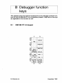
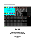
B Debugger function
keys
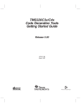
This appendix gives the keyboard assignments for the debugger symbolic 'functions for both the IBM 386 PC and compatibles (PCANSI . ITN) Some of the keys
are applicable to the simulator as well.
B.1
IBM 386 PC LH-keypad
F1
Ctrl
Shift
Aft
F2
------------------Contfrom
Help
Ctrl
----------
Shift _ _ _ _ _ .P~n.se_FH.!
AIt
!~'!.B~e~
Ctrl
Shift
Search
----------
AIt Toggle Hex
GetAdd;~
Ctrl
Shift ~-Wo~
AIt
-
De~t;Une-
-
Line
- Got~ L;'e-W~-~
- - - - Line
-
Ctrl
Shift
ToP cj File-End 0; Rle-
AIt
-Pag8Up - Page-DOWn
-L;'e-Up - -Lim. -DoWn
F9
72-TDS-351-01
F10
December 1992
B
20
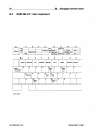
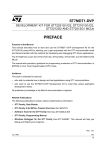
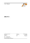
B.2
Debugger 'function keys
IBM 386 PC main keyboard
F1
Esc
F2
F3
F4
F5
F6
Fe
F7
1 I; =====~=~ =====~~~ ;: ~~u=~~~~=~~=~~==== ~
Re&esh
Help
Alt1
Inspect
Channel
Get Adlhu
Goto Line""
Una
Line -
3
4
5
6
7
8
9
Top
Retrace
Relocate
Into
Modify
Resume
Monitor
Select
Parameter
• Ctrl + key
72-TDS-351-01
December 1992
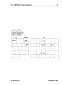
B.2 IBM 386 PC main keyboard
F9
21
F10
Top Of File
- Page
- Lin-;
End Of File Shift
Att
Up - -P;g-; D~wn
Up - -u-,,; D~
AIt
Backtrace
Backspace
Esc
Delete
Character
Refresh
Enter File
t
-
- - -CtrI
72-TDS-351-01
Finish
Exit File
t
December 1992
22
72-TDS-351-01
B
Debugger-function keys
December 1992
C DOS Extender
All of the tools provided in this toolset will only run on a '386 or higher PC.
This is because they use the full 32 bit capability of the '386 processor, to give
access to a large memory space and 32 bit registers. To do this, and still remain
compatible with MS-DOS, the applications use a DOS extender, and possibly an
extended memory manager.
C.1
Installation
The DOS extender used by the toolset is DOS/4GW. This is a subset of the
Rational Systems DOS extender DOS/4G, specially customised for use with the
WATCOM C/386 package, which is used to generate the tools in the toolset.
To use this it is simply necessary to ensure that the DOS extender executable
(DOS4GW. BX&:) is accessible through the PATH environment variable. The installation script places this file in the TOOLS subdirec1ory, which should be on the
path anyway.
Note that the version of the DOS extender supplied with the toolset is 1.8. This
version, or a later one, is required for reliable operation of the toolset, so if
a WATCOM product is also installed on the PC, ensure that the correct DOS
extender is found.
A limited amount of configuration may be required before tools from the toolset
can be run. When doing this it can be very useful to run PMINFO. This program
is provided by Rational Systems and will display useful information about the
system. If PMINFO will not run then consult section C.3 for further details of
configuration options.
The most common problem which may be faced when starting to run the toolkit
is ensuring that sufficient extended memory is available. Few applications use
this directly, and so it may be used by disk caches, RAM disks, or expanded
memory simulators. If this is the case some of these will have to be removed
from the system, or their memory requirements reduced.
If DOS/4GW finds that an extended memory manager which uses one of the main
disciplines is already installed, it will co-operate with it to use extended memory.
To find out if there is an extended memory manager present, run PMINFO.
In the final line of the output will be shown the switch method. This is the
technique which is used to switch between real mode and protected modes (see
section C.2.1 for the meaning of these terms). If there is no memory manager,
then PMINFO will use switch method 3 (386), and DOS/4GW will manage the
memory itself.
72-TDS-351-01
December 1992
24
C.2
C
DOS Extender
'386 Background
Most of the time the use of the DOS extender will be invisible to the user.
However if problems do occur the following sections give some background on
the concepts involved, before discussing the options which can be used to control
the DOS extender.
C.2.1
'386 basics
The '386 is able to operate in three basic modes:
real mode This is the default mode, in which the '386 emulates an 8086. All
registers are 16 bits wide, and so this is sometimes called 16 bit mode.
This is the mode in which MS-DOS runs, limiting a program to 640K
memory.
protected mode This mode supports hardware memory protection and paging.
On a '386 this gives an application access to upto 4Gbytes memory, and
all registers are extended to 32 bits, so it is sometimes known as 32 bit
mode. This is the mode in which tools from the toolset run.
virtual 86 mode In this mode the '386 emulates an 8086, however it is implemented as part of the protected mode, allowing the memory management
hardware to be used, and execution of certa.in instructions to be controlled. This is used by operating systems to support DOS applications,
which think they are running on a real 8086, however all input and output
is actually being redirected via the operating system. This mode is used
for the DOS prompt in MS-Windows. We won't consider this mode any
further.
Because it is pos~ible to switch between real mode and protected mode, an
application can be started from MS-DOS, running in real mode, switch to protected mode to run, and then return to MS-DOS for operating system support.
This switching is controlled by software called DOS extenders, which control the
execution of the application in protected mode, and make DOS calls available
to the application.
C.2.2
Memory
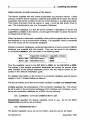
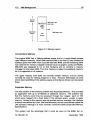
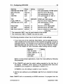
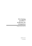
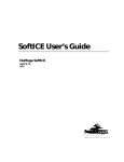
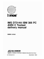
Since the introduction of the original 8086 based PC, various methods have been
used to make more memory available. As a result there are now a large number
of 'types' of memory possible on a PC. Figure C.1 shows a memory map of a
typical PC.
72-TDS-351-01
December 1992
C.2
25
'386 Background
Extended
Memory
........
l088K (lM + 64K)
Hip Memory Alea
-- - - - - ----- l024K (lM)
Upper
Memory
Area
........................ 640K
Conventional
Memory
High Memory Area
DOS
Memory
j
L . . - -_ _- - '
OK
Figure C.1 Memory layout
Conventional Memory
The original 8086 had a 1Mbyte address space, that is, it could directly access
upto 1Mbyte of memory. When IBM used the 8086 in the first PC they divided this
address space into 640K which could be filled with RAM, and the remaining 384K
was reserved for memory mapped hardware (such as graphic cards) and ROMs.
MS-DOS was designed to run on this hardware and so contains a memory
manager for the lower 640K. Thus this memory is called 'conventional memory'
as it is supported on all systems.
The upper memory area does not normally contain memory, and so cannot
normally be used for storing programs or data. However techniques do exist
which allow backfilling of this address space so that device drivers can be placed
there.
Expanded Memory
The first solution to the memory problem was Expanded Memory. This provided
an application with up to 32 Mbytes of additional memory. The problem was
that the memory could only be accessed through four 'pages', each of 16K
which were mapped into a fixed place in the address space, usually in upper
memory. Access to this memory was via another memory manager, the interface
to which was defined by Lotus, Intel and Microsoft, and so is sometimes called the
LIM standard, although it is more correctly named the EMS (Expanded Memory
Specification) .
This system had the advantage that it could be used on the 8086, but re72-TDS-351-01
December 1992
26
C
DOS Extender
quired additional hardware. Once the '386 had been introduced it became possible to implement expanded memory in software, using device drivers such as
BIOI386. Sys. However it is mainly used now for backward compatibility.
You may also come across the Enhanced Expanded Memory System (EEMS).
This is a superset of EMS which allows more flexibility in where the additional
memory will be mapped into the address space. In particular the .number of
pages, their size, and the addresses at which they may be mapped are all
variable.
Extended Memory
Once the '286 was introduced, memory above 1Mbyte became directly accessible. In the case of the '286 and '386SX this was up to 16 Mbytes, for the
'386DX and '486s it is 4Gbytes. The problem is that most of it is only available
to programs written to use these chips in protected mode, which MS-DOS was
not, and so most programs are still limited to 640K.
When an application is running in protected mode it is freed from the 640K limit
of DOS, thus all the memory on your PC is available to the application. However
the problem arises that several programs may want to use this memory at the
same time, and so a memory manager is required to ensure that the same block
of memory is only being used by one program at a time. While MS-DOS will
manage the memory below 640K an external manager is required for extended
memory. Several standards have evolved for these, in particular:
XMS Extended Memory Specification. This is the most common memory manager as it is distributed with DOS and MS-Windows in the form of
HIMBM. Sys. It will also manage memory between 640K and 1Mbyte on
machines that support it, and will handle the Higher Memory Area (see
below).
VCPI Virtual Control Program Interface. This is an extension of EMS which as
well as managing memory will switch between real mode and protected
mode to allow code to be run outside the first 1Mbyte. Thus it will usually
require a DOS extender. This interface to extended memory is most
commonly provided by running EMM386. SYS.
DPMI DOS Protected Mode Interface. This is similar to VCPI but also provides
limited communication between the protected application and DOS, as
well as providing some protection to memory and devices. DPMI is notable because is is provided by Windows 3, so an application running in
the DOS Prompt window can make DPMI calls.
One area of extended memory is accessible to programs running in real mode,
despite the apparent 1Mbyte limit. This is called the High Memory Area (HMA)
72-TDS-351-01
December 1992
C.2
'386 Background
27
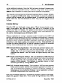
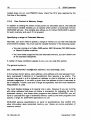
and is the first 64K of extended memory. This is directly accessible because of
the 80x86's segmented addressing scheme, in which the address is generated
by adding the segment address to an offset:
19
4 3
0
Segment
lo...-__B_a_se_3_d_dr_e_ss_ _.........:_0000_-.11
Offset
II....-__Off_s_et_ _-ll
15
Final
address
20 19
1.......:
+
0
0
1
If the segment base address is set to the maximum possible value, this is an
address 16 bytes short of 1Mbyte. However the segment can extend for 64K past
this address, and so most of the first 64K of extended memory is accessible to
a program running in real memory. On an 8086 this address would ~wrap-round'
to the bottom of memory, and so to retain compatibility most '286 and higher
PC's provide hardware which simulates this behaviour (indeed it is implemented
directly on a '486). Because this behaviour occurs when the 20th address bit is
set, the control logic is called the ~A20 gate'.
C.2.3
DOS Extenders
Although the '386 provides the program running on it with a large number of
facilities, it still requires an operating system to support it, most commonly MSDOS. However this introduces some problems, since MS-DOS runs in real mode,
and only provides memory management for conventional memory. To allow a
protected mode program to run, an interface between real mode and protected
mode is required - this is the DOS extender.
The DOS extender provides several features, the most important of which are:
• Load the application into memory and starts it running.
• Provide the application with operating system services, which it then
passes on to DOS for execution.
• Provide the application with memory management functions, independently of the actual memory manager which is being used.
72-TDS-351-01
December 1992
28
C.3
C
DOS Extender
Configuring DOS/4GW
The DOS extender which is used with the INMOS toolset is DOS/4GW. This
section describes how to use the D084G environment variable to suppress the
banner that is displayed by DOS/4GW at startup. It also explains how to use the
D0816M environment variable to select the switch mode setting, if necessary,
and to specify the range of extended memory in which DOS/4GW will operate. DOS/4GW is based on Rational Systems' DOS/16M 16-bit protected mode
support; hence the D081611 environment variable name remains unchanged.
C.3.1
Suppressing the DOS/4GW Banner
The banner that is displayed by DOS/4GW at startup can be suppressed by
issuing the following command:
••t. DOS4G=quiet.
Do not insert a space between D084G and the equals sign. A space to the right
of the equals sign is optional.
C.3.2
Changing the Switch Mode Setting
In almost all cases, DOS/4GW programs can detect the type of machine that it is
running on, and automatically choose a real to protected mode switch technique.
For the few cases in which this default setting does not work the D081611 DOS
environment variable is provided, which overrides the default setting.
The switch mode setting can be changed by issuing the following command:
.et. D0816M=value
Do not insert a space between D081611 and the equals sign. A space to the
right of the equals sign is optional.
The table below lists the machines and the settings you would use with them. The
status column indicates if the setting will be automatically recognised (marked
auto) or if the D081611 variable must be set (marked required). For IBM PS/2
model 55's the variable may need to be set for certa.in machines, and so is
marked optional.
72-TDS-351-01
December 1992
C.3
Configuring DOS/4GW
Machine
'386/'486 with DPMI
NEC 98-series
PS/2
'386/'486
Status
auto
required
auto
auto
29
Setting
0
1t
2
3t
Comment
Set automatically if DPMI active
Must be set for 98-series
Set automatically for PS/2
Set automatically for '386 or
'486
'386
auto
INBOARD 80386 with Intel Inboard
Fujitsu FMR-70
required 5
Must be set for Fujitsu FMR-70
11
'386/'486 with VCPI auto
Set automatically if VCPI
detected
Hitachi 832
required 14
Must be set for Hitachi B32
OKI if800
required 15
Must be set for OKI if800
IBM PS/2 model 55 optional 16
May be needed for some PS/2
model55s
t The mnemonic "9801" may be used instead of the number
t The mnemonics "386" or "80386" may also be used
The following procedure shows how to test the switch mode settings.
1 If you have one of the machines listed below, set the 0081611 environment variable to the value shown for the machine and specify a range of
extended memory. For example, if your machine is an NEC g8-series, set
D0816K=1@2M-411. See section C.3.3, "Fine Control of Memory Usage",
later in this chapter for more information about setting memory usage.
Machine
NEC 98-series
Fujitsu FMR-60,-70
Hitachi 832
OKI if800
Setting
1
5
14
15
Before running toolset applications, check the mode setting by following
this procedure:
2 Run PMINFO and note the switch setting reported by the last line of
the display. (PMINFO, which reports on the protected-mode resources
available to your programs, is described in section C.4.)
If PMINFO runs, the setting is usable on your machine.
3 Add the new setting to your AUTOEXEC . BAT file if you needed to change
them.
Note: PMINFO will run successfully on 80286 machines. If a program from the
72-TDS-351-01
December 1992
C
30
DOS Extender
toolset does not run, and PMINFO does, check the CPU type reported by the
first line of the display.
C.3.3
Fine Control of Memory Usage
In addition to setting the switch mode portion as described above, the D081611
environment variable enables you to specify which portion of extended memory
DOS/4GW will use. The variable also allows you to instruct DOS/4GW to search
for extra memory and use it if it is present.
Specifying a range of Extended Memory
Normally, you don't need to specify a range of memory to use with the D081611
environment variable. You must use the variable however in the following cases:
• You are running on a Fujitsu FMR-series, NEC g8-series OKI if800-series
or Hitachi B-series machine.
• You have older programs that use extended memory, but don't follow one
of the standard disciplines.
If neither of these conditions applies to you, you can skip this section.
The genera.1 syntax is:
.et DOS1611=[switch mode][@start_address [-end_address]][: size]
In the syntax shown above, start_address, end_address and size represent numbers, expressed in decimal or in hexadecimal (hex requires a Ox prefix). The
number may end in a It to indicate an address or size in kilobytes, or an M to
indicate megabytes. If no suffix is given than the address of size is assumed to
be in kilobytes. If both a size and a range are speci'fied, than the more restrictive
interpretation is used.
The most flexible strategy is to specify only a size. However if you are running
with other software that does not follow a convention for indicating its use of
extended memory, and these other programs start before DOS/4GW, you will
have to calculate the rage of extended memory used by the other programs and
specify a range for DOS/4GW applications to use.
DOS/4GW ignores specifications (or parts of speci'fications) that conflict with
other information about extended memory use. Below are some examples of
memory control:
72-TDS-351-01
December 1992
C.3
Configuring DOS/4GW
31
set 0081611=1@2m-4m Mode 1, for NEC 9B-series machines, and use ex-
tended memory between 2.0 and 4.0MB.
set D081611=: iN
Use the last full megabyte of extended memory, or as
much as available lim,ited to 1MB.
set D0816M=@211
Use any extended memory ava,ilable above 2MB.
set 00816M=@0-5m
Use any available extended memory from 0.0 (really
1.0) to 5.0MB.
set 0081611=:0
Use no extended memory.
As a default condition toolset applications take all available extended memory
that is not otherwise in use. The default memory allocation strategy is to use
extended memory if available, and overflow into DOS (Iow) memory.
In a VCPI or DPMI environment, the start_address and end_address arguments
are not meaningful. DOS/4GW memory under these protocols is not allocated
according to specific addresses because VCPI and DPMI automatically prevent
address conflicts between extended memory programs. You can specify a size
for memory managed by VCPI or DPMI, but DOS/4GW will not necessarily allocate this memory from the highest available extended memory address, as it
does for memory allocated under other protocols.
Using Extra Memory
Some machines contain extra non-extended, non-conventional memory just below 16MB. When DOS/4GW runs on a Compaq 3B6, it automatically uses this
memory because the memory is allocated according to a certain protocol, which
DOS/4GW follows. Other machines have no protocol for allocating this memory.
To use the extra memory that may exist on these machines, set 00816M with
the + options:
set 0081611=+
Setting the + option causes DOS/4GW to search for memory in the range from
FAOOOO to FFFFFF and determine whether the memory is usable. DOS/4GW
does this by writing into the extra memory, and reading what it has written.
In some cases, this memory is mapped for DOS or BIOS usage, or for other
system uses. If DOS/4GW finds extra memory that is mapped this way, and is
not marked read-only, it will write into that memory. If this memory is in use, this
will cause a crash, but won't damage your system.
72-TDS-351-01
December 1992
32
C.3.4
C
DOS Extender
Setting Runtime Options
The DOS1611 environment variable sets certain runtime options for all DOS/4GW
programs running on the same system. Most of these are only useful when
developing applications under DOS/4GW, and are listed only for completeness.
However they may be useful when coercing toolset applications to run on machines that are not fully AT-compatible.
To set the environment variable, the syntax is:
••t. DOS1611=[switch_made_setting] A options
Note: Some command line editing TSRs, such as CED, use the caret {A} as a
delimiter. If you want to set D081611 using the above syntax above while one of
these TSRs is resident, modify the TSR to use a different delimiter.
These are the options:
OxOl check A20 line. This option forces DOS/4GW to wait until the A20 line is
enabled before switching to protected mode. When DOS/4GW switches
to real mode, this option suspends your program's execution until the A20
line is disabled, unless an XMS manager (such as H:IMEM. Sys) is active.
If an XMS manager is running, your program's execution is suspended
until the A20 line is restored to the state it had when the CPU was last in
real mode. Specify this option if you have a machine that runs DOS/4GW
but is not truly AT-compatible. For more information on the A20 line, see
section C.3.5 "ContrOlling Address line 20".
Ox02 prevent initialisation of VCPI. By default, DOS/4GW searches for a VCPI
server and, if one is present, forces it on. This option is useful if your
application does not use EMS explicitly, is not a resident program, and
may be used with '386-based EMS simulator software.
Ox04 directly pass down keyboard status calls. When this option is set, status
requests are passed down immediately and unconditionally. When disabled pass-downs are limited so the 8042 auxiliary processor does not
become overloaded by keyboard polling loops.
Oxl0 restore only changed interrupts. Normally, when a DOS/4GW progra.m
terminates, all interrupts are restored to the values they had at the time
of program startup, When you use this option, only the interrupts changed
by the DOS/4GW program are restored.
Ox20 set new memory to 00. When DOS/4GW allocates a new segment or
increases the size of a segment, the memory is zeroed. This can help
you find bugs having to do with uninitialized memory. You can also
72-TDS-351-01
December 1992
C.3
Configuring DOS/4GW
use it to provide a consistent working
programs were run earlier. This option
or expansions which are made through
function 48H or 4AH). This option does
a compiler's malloe () function.
33
environment regardless of what
only affects segment allocations
the DOS/4GW kernel (with DOS
not affect memory allocated with
Ox40 set new memory to FF. When DOS/4GW allocates a new segment or in-
creases the size of a segment, the memory is set to OxFF bytes. This
is helpful in making reproducible cases of bugs caused by uninitialized
memory. This option only affects segment allocations or expansions
which are made through the DOS/4GW kernel (with DOS function 48H
or 4AH). This option does not affect memory allocated with a compiler's
malloe () function.
Ox80 new selector rotation. When DOS/4GW allocates a new selector, it usually
looks for the first available (unused) selector in numerical order starting
with the highest selector used when the program was loaded. When the
option is set, the new selector search begins after the last selector was
allocated. This causes new selectors to rotate through the range. Use
this option to find references to stale selectors, i.e., segments that have
been canceled or freed.
C.3.5
Controlling Address line 20
This section describes how DOS/4GW uses address line 20 (A20) and describes
the related D081611 environment variable settings. It is unlikely that you will need
to use these settings.
Because the 8086 and 8088 chips have a 20-bit address space, their highest
addressable memory location is one byte below 1MB. If you specify an address
at 1MB or over, which would require a twenty-first bit to be set, the address wraps
back to zero. Some parts of DOS depend on this wrap, so on the 80286 and
80386, the twenty-first address line is disabled. To address extended memory,
DOS/4GW enables the twentY-'first address bit (the A20 line). The A20 line must
be enabled for the CPU to run in protected mode, but it may be either enabled
or disabled in real mode.
By default, when DOS/4GW returns to real mode, it disables the A20 line. Some
software depends on the line being enabled. DOS/4GW recognises the most
common software in this class, the XMS managers (such as HIMEM. 8YS), and
enables the A20 line when it returns to real mode if an XMS manager is present.
For other software that requires the A20 line to be enabled, use the A20 option.
The A20 option makes DOS/4GW restore the A20 line to the setting it had when
DOS/4GW switched to protected mode. Set the environment variable as follows:
72-TDS-351-01
December 1992
34
C
DOS Extender
••t. D0816M=A20
To specify more than one option on the command line, separate the options with
spaces.
The D081611 variable also lets you specify the length of the delay between
a DOS/4GW instruction to change the status of the A20 line and the next
DOS/4GW operation. By default, this delay is 1 loop instruction when DOS/4GW
is running on a '386 machine. In some cases, you may need to specify a longer
delay· for a machine that will run DOS/4GW but is not truly AT-compatible. To
change the delay, set the D081611 to the desired number of loop instructions,
preceded by a comma:
••t. D081611=, loops
72-TDS-351-01
December 1992
C.4
C.4
PMINFO
35
PMINFO
Purpose Measures the performance of protected/real-mode sWitching and extended memory.
Syntax PMINFO. BD
Notes The time-based measurements made by PMINFO may vary slightly from
run to run.
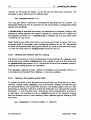
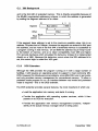
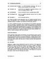
Example The following example shows the output of the PMINFO program on
an 80486 AT-compatible machine.
Prot.ect.ed Mode and zxt;ended Memory Perfo:mance Mea.urement. -- 3.95
Copyright. 1988, 1989, 1990 by Rat.iona1 ~.t.. . . , Xnc.
DOS memory
Ext.ended muaory
639
640
477
7040
7168
7040
21.2 (0.0)
42.1 (0.0)
21.2 (0.0)
40.1 (0.5)
CPU i . 33.7 HIlI: 80486.
K byt.e. configured (according t.o BXOS).
K byt.es phy.ically pr. .ent. (S&~).
K byt.e. available for DOS/l6M progrllDl8.
(DOS/l6M memory range 1088K t.o 8128K)
MS/sec word t.ransfer rat.e (wait. .t.ate.).
MS/.ec 32-bit t.ran.fer rate (wait. .t.at.e.).
Overall cpu and IUIDOry perfonuLnce (non-float.ing point) for t.ypical
DOS progrmu is 8.32 +/- 0.67 t.imes an 8MBI: DD! PC/A.T.
=
Prot.ect.ed/Raal .wit.ch rat.e
16124/.ec (62 u.ec/••it.ch, 32 up
u.ing DOS/l6M ••itch mode 3 (386).
+
29 down),
The top information line shows that the CPU is an Intel 80486 processor
running at 33.7MHz. Below are the configuration and timings for both the
DOS memory and the extended memory. If the computer is not equipped
with extended memory, or none is available for DOS/4GW, the extended
memory measurements may be omitted ("--").
The line "according to BIOS" shows the information provided by the BIOS
(interrupts 21 hand 15h function 88h). The line "SETUP", if displayed,
is the configuration obtained directly from the CMOS RAM as set by
the computers setup program. It is only displayed if the numbers are
different from those in the BIOS line. They will be different for computers
where the BIOS has reserved memory for itself or if another program
has allocated some memory and is intercepting the BIOS configuration
requests to report less memory available than is physically con-figured.
The "DOS/16M memory range", if displayed, shows the low and high
addresses available to DOS/4GW in extended memory.
Below the configuration information is information on the memory speed
(transfer rate). PMINFO tries to determine the memory architecture.
Some architectures will perform well under certain circumstances and
poorly under others; PMINFO will show both the best and worst cases.
72-TDS-351-01
December 1992
36
C
DOS Extender
The architectures detected are cache, interleaved, page-mode (or static
column), and direct. Measurements are made using 32-bit accesses and
reported as the number of megabytes per second that can be transferred.
The number of wait states is reported in parentheses. The wait states
can be a fractional number, like 0.5, if there is a wait state on writes
but not on reads. Memory bandwidth (Le. how fast the CPU can access memory) accounts for 600/0 to 700k of the performance for typical
programs (that are not heavily dependent on floating-point arithmetic).
A performance metric developed by Rational Systems is displayed, showing the expected throughput for the computer relative to a standard 8MHz
IBM PC/AT (disk accesses and floating point are excluded). Finally the
speed with which the computer can switch between real and protected
mode is displayed, both as the maximum number of round-trip switches
that can occur per second, and the time for a single round trip switch,
broken out into the real-to-protected (up) and protected-to-real (down)
components.
72-TDS-351-01
December 1992
C.5
C.5
RMINFO
37
RMINFO
Purpose Supplies configuration information and the basis for real/protectedmode switching in your machine.
Syntax RMINFO. BXE
Notes RMINFO starts up DOS/4GW, but stops your machine just short of switching from real mode to protected mode and displays configuration information about your computer. The information shown by RMINFO can help
determine why DOS/4GW applications won't run on a particular machine.
Run RMINFO if PMINFO does not run to completion.
Example The following example shows the output of the RMINFO program on
an 80486 AT-compatible machine.
Con~iguration in~or.mation:
Machine
con~iguration:
Xnte1 80486 proce••or(de1ay= unknown)
BXOS:
No
~riplefault flag:
On
A.ddre•• line 20 rigor: Ho
line 20:
Off
Addre.. line 20 orig.: Off
Operating .y.tem. i . DOS 5.0
VDXSlt device found:
No
QZn device found:
No
XMS .y.tem. found:
No
Ba. an PC or
n
Addr...
Configured ..-ory:
B. . e 1024K, Size 1S360K,
Actual IMIDOry:
B. .e 1024K, ~op 81~2K
Unallocated memory:
7l68K
DOS/16M ver.ion 3. ~S
~i. i . the fir.t copy of DOS/l6M.
Switch control flag'.:
0000
Switch method:
3 (80386)
Available memory:
7l68K [0]
Ho VCPX page table.
VCPX not in u.e.
End of configuration info~tion
~op
16384K
The information provided by RMINFO includes:
Triple fault flag Whether triple faulting is used to switch back to real
mode from protected mode.
Address line 20 rigor Whether DOS/4GW rigorously controls enabling
and disabling of Address line 20 when switching modes.
Address line 20 Current state of Address line 20.
Address line 20orig. Original state of Address line 20.
VDISK device found Whether your system has any software using extended memory under the VDISK discipline.
72-TDS-351-01
DecerTlber 1992
C
38
DOS Extender
QEXT device found Whether your system has any software using extended memory under the QEXT discipline.
XMS device found Whether your system has any software using extended memory under the XMS discipline.
Configured memory Amount of memory DOS/4GW will try to use.
Actual memory Amount of memory DOS/4GW can actually use.
This is the . .. This number will vary according to how many copies of
DOS/4GW or DOS/16M-based applications are currently active
on your system.
VCPI (not) in use If your system has any software using extended memory under the VCPI discipline.
72-TDS-351-01
December 1992