1
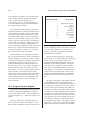
ANALYZER PANEL
10-5
ured, their required input amplitude for linear operation may be less than the approximately 2 mV sensitivity of the phase meter. In this case, the signal at
the BNC connector labeled MONITOR OUTPUT
(GENERATOR AUXILIARY SIGNALS) can be
connected to the CHANNEL-B connector to serve
as the phase reference, instead of selecting GENMONitor at CHANNEL-B. This MONITOR OUTPUT signal is a constant amplitude signal of approximately 1 Volt, even when the generator outputs are
at very low amplitudes.
Either CHANNEL-A or CHANNEL-B may be selected as GEN-MONitor. System One software will
automatically correct the phase measurements so
that the GEN-MONitor channel is the reference and
phase measurements are relative to it. If both channels A and B are set to GEN-MONitor, channel A
will again be the reference. The panel display range
can be fixed in +/-180 degree display format (deg1),
-90 to +270 degree format (deg2), 0 to +360 degree
format (deg3), or can be automatically selected as +/180 degrees or 0-360 degrees, depending on the
measured value (deg).
Polarity testing may be performed with System
One if the BUR-GEN module is present or another
assymetrical (low duty cycle) tone burst signal is
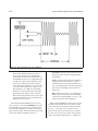
available. The signal must consist of a tone burst of
approximately 30% duty cycle, with the leading
edge of the burst sinewave being positive-going.
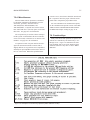
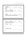
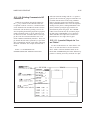
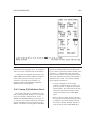
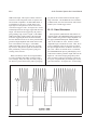
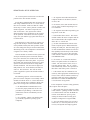
All tone bursts from the BUR-GEN module are initially positive-going. Polarity mode is selectable as
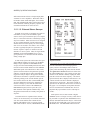
a unit on the PHASE line of the ANALYZER panel,
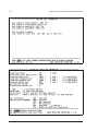
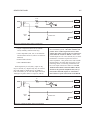
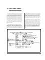
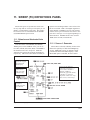
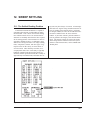
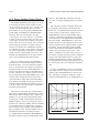
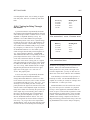
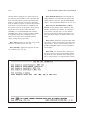
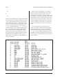
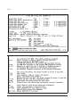
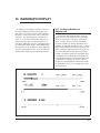
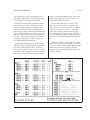
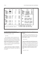
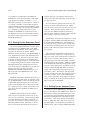
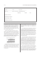
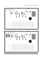
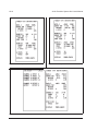
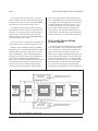
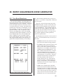
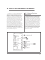
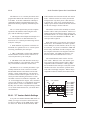
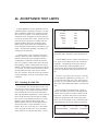
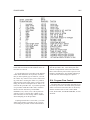
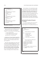
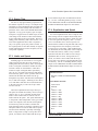
shown in Figure 10-4. When POL is selected, the
PHASE indication can be only 0 or +180. The 0 indication shows that the measured signal is positivegoing; a +180 indication indicates that a polarity reversal has occurred somewhere between the generator output and the analyzer input.
Polarity testing is a requirement when testing the
wiring of mixing consoles, studios, and other sophisticated multi-channel audio systems to assure that no
inadvertent cable transpositions have taken place.
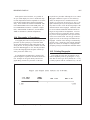
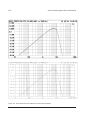
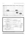
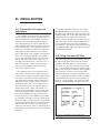
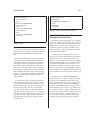
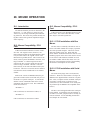
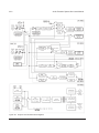
Figure 10-4 Analyzer Panel in Polarity Testing
Mode
10.4. Filter Frequency Control
The BP/BR FREQ line permits control of the tuning of the bandpass/bandreject filter of the tunable
filter module. Two modes are selectable—AUTO
or Hz. In the AUTO mode, the filter will automatically be tuned to the generator frequency during frequency or amplitude sweeps where generator is the
signal source. In sweeps with an EXTERNal source
(such as the signal from a pre-recorded test tape or
disk or a distant-origination signal), AUTO mode
steers the filter to the frequency being measured by
the analyzer frequency counter. In panel mode with
AUTO selected, the filter is also steered by the analyzer frequency data if the LEVEL voltmeter reading is above approximately 8 millivolts; below that
level, the filter will be locked to the last frequency
measured by the frequency counter.
When Hz is selected, the filter can be fixed-tuned
to any frequency from 10 Hz to 200 kHz (+/-3%) by
making a numeric entry in this field. If it is desired
to transfer the present value of the FREQUENCY
counter to this field, you may place the cursor on
the BP/BR FREQ units (Hz) field and press <Enter>. When an ANLR BP/BR sweep is selected at
SOURCE-1 or SOURCE-2, it will take control of
the filter frequency during the sweep even if the
ANALYZER panel selection was fixed at a specific
frequency.