1
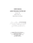
PROGRAMM ABLE DIGITAL CONTROLLER USER MANUAL LOAD BANKS W E HE TH HT TH WIIT DIGITAL SOLUTION 2004 Load Technology, Inc. 11/18/2004 Information in this document is subject to change without notice and does not represent a commitment on the part of Load Technology, Inc (LOADTEC). No part of this Operator Manual may be reproduced, stored in a retrieval system (except as provided for by Load Technology, Inc.), or transmitted in any form or by any means electronic or mechanical, including photocopying and/or recording, for any purpose, without the express written consent of Load Technology, Inc. Copyright © 2004 by Load Technology, Inc; All Rights Reserved. Printed in the United States of America Load Technology, Inc. 4225 Production Court. Las Vegas, NV 89115 U.S.A. LoadView® is a trademark of Load Technology, Inc. Microsoft is a registered trademark; Windows and Excel are trademarks of the Microsoft Corporation. DOCUMENTATION/DRAWING TERMS OF USE This documentation and drawings (document) provided are subject to the following rules, guidelines, policies, and conditions. OWNERSHIP Load Technology ( LOADTEC ) owns the contents of this document. The inclusion with equipment or supply after in support of purchased equipment or parts does not transfer ownership to the purchaser or owner of the equipment that this document details. Specific payment or purchase of copy(s) of this document does not transfer ownership. COPYRIGHT All content included on these pages are protected by U.S. and international copyright laws. Further, even if not specifically noted as copyrighted, we consider this document in its entirety as copyrighted. By using this document, you agree to honor all applicable copyright laws and practices. USE OF PROPRIETARY INFORMATION This document includes detailed design information that is confidential, proprietary, and may include trade secrets of LOADTEC. This information is not meant for public dissemination, but made available only to you, the customer, for repair and maintenance purposes only. By accessing this information, you are representing that your use is for repair and/or maintenance only. You further represent that you will not use any of the information for any purpose other then repair and/or maintenance or disseminate to any third party or competitor for any reason. WARRANTIES AND DISCLAIMERS The contents of this document are provided without any warranties, either express or implied, and it explicitly disclaims any implied warranties of merchantability or fitness for a particular purpose. APPLICABLE LAW AND DISPUTE RESOLUTION By accessing this document, you agree that the laws of the State of Nevada will govern all disputes that arise concerning the use of this document. Any disputes brought concerning the terms of this agreement shall be in a state or federal court located in the State of Nevada, Clark County. DocUseTerms11032010(2).doc Contents At a Glance 1 - System Description 2 - Functional Overview 3 - The Control Panel 4 - System Setup 5 - Operation 6 - The Messaging System Glossary Index Programmable Digital Controller 2004 Load Technology, Inc. Table of Contents Load Bank Programmable Digital Control System Table of Contents List of Illustrations ....................................................................................................... iii 1.0 System Description ...................................................................................................1 2.0 Functional Overview ................................................................................................2 2.1 The Power Meter System.....................................................................................2 3.0 The O.I.P. (Operator Interface Panel)......................................................................4 3.1 The Front Panel Keys ..........................................................................................5 3.1.1 Power On/Off Key ..........................................................................................5 3.1.2 The Soft Keys .................................................................................................5 3.1.3 The Mode Key ................................................................................................6 3.1.4 The Stop Key ..................................................................................................7 3.1.5 The Start Key..................................................................................................7 3.1.6 The Load On/Off Key .....................................................................................7 3.1.7 The Function Select Key .................................................................................7 3.1.8 The Clear/Reset Key .......................................................................................8 3.1.9 The Enter Key.................................................................................................8 3.1.10 The Arrow Keys............................................................................................8 3.1.11The Lamp Test Key........................................................................................8 3.2 The LCD Screen...................................................................................................9 3.2.1 The Soft-Key Menus.......................................................................................9 3.3 The Status Indicator LEDs................................................................................13 4.0 System Setup...........................................................................................................14 4.1 Setup Screens .....................................................................................................14 4.1.1 The Numeric Entry Field...............................................................................15 4.1.2 The Toggle Entry Field .................................................................................16 4.2 Auto Exercise Setup...........................................................................................16 4.2.1 Auto Exercise Clock Setup............................................................................16 4.2.2 Auto Exercise Sequence Setup ......................................................................18 4.2.3 Auto Exercise Alarm Setup Screen................................................................19 4.3 Auto Loading Setup Screen ...............................................................................20 4.4 Base Loading Setup screen ................................................................................22 4.5 Regen Load Setup Screen ..................................................................................23 4.6 Step Value Setup Screen....................................................................................23 4.7 Set Clock Screen ................................................................................................24 Programmable Digital Controller. i 2004 Load Technology, Inc. Operator's Manual 4.8 Sensor Calibration .............................................................................................24 4.8.1 The Calibration Menu ...................................................................................24 4.9 The License Manager ........................................................................................30 5.0 Operation................................................................................................................31 5.1 Manual Mode.....................................................................................................31 5.1.1 Manual Load Setting .....................................................................................32 5.1.2 Load Dump Override ....................................................................................33 5.1.3 Jogging the Load Command..........................................................................33 5.2 Auto Mode..........................................................................................................34 5.2.1 Auto Exercise ...............................................................................................34 5.2.2 Auto Loading ................................................................................................37 6.0 The Messaging System............................................................................................40 6.1 Viewing Messages ..............................................................................................40 6.1.1 Viewing Message Details..............................................................................41 6.2 Operational Messages........................................................................................42 6.3 Exercise Messages..............................................................................................44 Glossary........................................................................................................................47 Index.............................................................................................................................48 2004 Load Technology, Inc. ii Programmable Digital Controller - 10/3/2004 Table of Contents List of Illustrations Figure 1 - Load Bank System Diagram............................................................................2 Figure 2 - The O.I.P. (Operator Interface Panel).............................................................4 Figure 3 - The Soft Keys ..................................................................................................5 Figure 4 - The LCD Display ............................................................................................9 Figure 5 - The Main Menu...............................................................................................9 Figure 6 - The Status Menu ...........................................................................................10 Figure 7 - The Meter Select Menu .................................................................................11 Figure 8 - The System Message Menu............................................................................12 Figure 9 - The Setup Menu Keys....................................................................................12 Figure 10 - Setup Screen ...............................................................................................14 Figure 11 - Auto Exercise Clock Setup Screen ...............................................................16 Figure 12 - Auto Exercise Sequence ..............................................................................18 Figure 13 - Auto Loading Setup Screen .........................................................................20 Figure 14 - Load/Unload rate........................................................................................ 21 Figure 15 - Base Loading Setup Screen .........................................................................22 Figure 16 -- Regen Setup Screen ...................................................................................23 Figure 17 - Step Setup Screen........................................................................................23 Figure 18 - Set Clock Screen .........................................................................................24 Figure 19 - The Calibration Menu Keys ........................................................................25 Figure 20 - Voltage Calibration Screen .........................................................................25 Figure 21 - Default Voltage Screen ...............................................................................25 Figure 22 - Voltage Zero Screen....................................................................................26 Figure 23 - Current Calibration Screen.........................................................................27 Figure 24 - Default Current Screen ...............................................................................27 Figure 25 - Current Zero Screen ...................................................................................28 Figure 26 - Generator Current Calibration Screen........................................................28 Figure 27 - Default Generator Current Screen ..............................................................29 Figure 28 - Generator Current Zero Screen ..................................................................29 Figure 29 - License Manager ........................................................................................30 Figure 30 - Manual Load Setting...................................................................................32 Figure 31 - Load Dump Active Screen ...........................................................................33 Figure 32 - Auto Exercise Status ...................................................................................34 Figure 33 - Message Viewer ..........................................................................................40 Figure 34 - Message Detail Window..............................................................................41 Programmable Digital Controller. iii 2004 Load Technology, Inc. Operator Manual 1.0 System Description LOADTEC's Load Banks with the Programmable Digital Controller are designed to provide and advanced test and measurement functions. These systems work in concert with the power generation system. They provide automated testing, constant load control, quick loading in response to regenerative surges, and initial startup load to bring turbo boost up quickly. The Load Bank control system is made up of a DMC (Digital/Metering Controller), OIP (Operator Interface Panel), LSC (Load Step Controller), and LMC (Load Module Controller). The OIP (Operator Interface Panel) communicates with the internal DMC (Digital/Metering Controller) and can be mounted integral to the Load Bank or remote mounted at a separate location. A simple to more complex system can be constructed using these modules. A Load Bank system can contain up to eight (8) LMC (Load Module Controller). These modules provide the safety and main I/O control in the system (i.e. internal power control, fan(s) control, etc). A system may not use this module while a more complex system can use a number of these devices. The control of each of the load steps is provided for by the LSC (Load Step Controller). A system may contain only one of these modules while more complex system can contain many of the LSCs. Both the LMC (Load Module Controller) and the LSC (Load Step Controller) are commanded and controlled by the DMC (Digital/Metering Controller). Operator Manual Load Bank Programmable Digital Controller DMC (Digital Metering/Controller) Dual Processor based Metering and Control Module Resistive Load Steps Inductive Load Steps LSC (Load Step Controller LMC (Load Module Controller LSC (Load Step Controller LMC (Load Module Controller O.I.P. Operator Interface Panel Safety inputs Power Control Fan Controls Etc. Figure 1 - Load Bank System Diagram The Load Bank is operated via the OIP (Operator Interface Panel). Again, this control panel may be mounted integrally to the Load Bank or remote mounted at a separate location. 2.0 Functional Overview The main function of a Load Bank is to place an electrical load on a power source, usually a generator, generator system, or a UPS (Uninterruptible Power Supply). This is known as the Test Source. The electrical load is provided by the resistive elements contained within the Load Bank. These elements are designed to provide accurate and stable loads for controlled testing of the power source. Resistive elements are sized by the amount of Real Power (KW - kilowatts) they absorb at a given voltage. This is also known as a Load Step. Once configured, the Programmable Digital Control System will automatically add or remove load as a function of the measurements made by the system and the selected operational mode. In order to make these load adjustments, both the Load Bank and generator power are measured as well as the voltage and frequency. 2.1 The Power Meter System A dedicated processor in the DMC (Digital/Metering Controller) performs the Power Meter functions (the metering). The metering system is Page 2 Programmable Digital Controller - 10/3/2004 Operator Manual responsible for measuring the output of the voltage and current sensors and making all required calculations. The Metering System scans each of the voltage (V1, V2, and V3) inputs, current (A1, A2, and A3) inputs, and the generator current inputs at a minimum high sample rate of 8 KHz. The real power is calculated from the instantaneous power as follows: KW = 1T pdt T ∫0 Depending on the system type, there may be a power measurement made for each phase (in a 3-phase system) or a single CT may be used on one phase. The metering system is a true R.M.S. (root-mean-square) measurement system. The R.M.S. value of each voltage and current input is computed as shown. These computations are updated at the high sample rate. The calculations are completed at each zero crossing of the phase "A" voltage input. T Vrms = 1 V 2 (t )dt T ∫0 Note: When comparing or calibrating the voltage and current measurements of the Metering System, be sure to use a true rms reading DVM. Many meters are average reading type and will not provide an accurate reading; they do not compensate for typical distortions present in the sinusoid waveform. The voltage measurement system is capable of measuring voltages as high as 660 Vrms at a crest factor of 1.414. As the measured voltage decreases, the maximum crest factor allowed increases -- the limit is the peak voltage. Operator Manual 3.0 The O.I.P. (Operator Interface Panel) Figure 2 - The O.I.P. (Operator Interface Panel) The OIP is the interface to the Load Bank system. From this panel, the system can be programmed and controlled. It is made up of a 16-key keypad, a 128 x 64 Graphic LCD Display, and 8 status indicators. The OIP can be integrally mounted to the Load Bank or remote mounted via a standard CAT-5 cable interface. Page 4 Programmable Digital Controller - 10/3/2004 Operator Manual 3.1 The Front Panel Keys The OIP contains 16 special function keys as shown in figure 2. The following is a description of each of these keys. 3.1.1 Power On/Off Key The Power On/Off Key is used to toggle the power on and off. Turning the power off simply powers down the OIP. The DMC (Digital/Metering Controller) electronics will always be powered on if a power source is provided. When the OIP is powered down, none of the automated load functions will be active and no loads will be applied. 3.1.2 The Soft Keys Figure 3 - The Soft Keys F1, F2, and F3 are the Soft-Keys. These are called Soft-Keys because their function is defined by the software and will change based on the current operational mode of the system. The function of each of these keys is indicated by the top lines of the LCD display. In the example shown in figure 3, the F1 Key is used to set the load, F2 is used to access the system messages, and F3 is used to access the setup functions. Operator Manual Some of the operational modes have more than 3 functions to select. For example, in the setup mode there are 8 functions. When there are more than 3 SoftKey functions, markers will be shown to indicate there are more functions to the right or left. In the example shown, there are more functions to the right. Pressing the Right Arrow Key will scroll the functions one position to the right. When a marker is shown on the left side, it indicates that there are more functions to the left. Pressing the Left Arrow Key causes the functions to scroll one position to the left. 3.1.3 The Mode Key The control system can function in one of three operating modes: Off, Manual, and Auto (automatic). The Mode Key is used to cycle between each of these modes. Pressing this key while in the Off mode moves the system to the Manual mode. If in Manual, pressing this key will move the system to the Auto mode, and pressing the key while in Auto returns the system to the Off mode. Page 6 Programmable Digital Controller - 10/3/2004 Operator Manual 3.1.4 The Stop Key The Stop Key is used to stop any action being performed by the control system and disconnect the load. If the Load Bank has cooling fans, they will also be turned off when this key is pressed. The LCD screen will be restarted at its power up state. 3.1.5 The Start Key The functions performed to start the system vary based on the system type. The function of the Start Key depends on the current operational mode of the system. If in the Manual mode, then the Start Key is used to "Start" the system. Starting the system can be thought of as preparing it for loading (turning fans on, check control voltages, etc...). If the system is in the Auto mode and Auto Exercising has been configured and enabled, then pressing the Start Key will cause an Auto Exercise test to be started now. 3.1.6 The Load On/Off Key This key is only used when the system is in the Manual mode. Pressing the Load On/Off Key when in the Manual mode with load applied causes the system to save the current load setting then disconnect the load. Pressing this key again causes the load value to be returned to its previous setting. In essence, this key toggles the load On/Off. 3.1.7 The Function Select Key This key controls the Soft-Key function menus. Soft-Key functions are arranged in logical groups that make up a menu system. The Function Select Key is used to cycle between these groups (or menus). There are three main Soft-Key menus. These are: 1. The Main Menu 2. The Status Menu 3. The Meter Select Menu Operator Manual 3.1.8 The Clear/Reset Key This key has multiple functions. If an error message is being shown in the message area of the screen, then pressing this key will clear the error and reset the Alarm indicator LED. If entering numerical values, pressing this key will clear the numeric entry field. Pressing this key in an input screen will exit that screen. 3.1.9 The Enter Key In general, the Enter Key is used to Enter the given selection or data. When editing a numeric value in a Numeric Entry Field, the Enter Key is used to accept the value and place it in the value field. When viewing messages, the Enter Key is used to view detailed information of the selected message. 3.1.10 The Arrow Keys There are four Arrow Keys on the front panel. These are the Up Arrow, Down Arrow, Left Arrow, and Right Arrow Keys. These keys have multiple uses depending on the operational mode of the system. When in the Manual Mode and not in a Numeric Entry Field, the Up and Down Arrow Keys are used to jog the load setting up and down. When in a Numeric Entry Field, the Left and Right Arrow Keys are used to move the cursor within the field and the Up and Down Arrow Keys are used to increment/decrement the selected digit. 3.1.11The Lamp Test Key The Lamp Test Key is used to perform a simple LED and LCD display test. Each of the LED indicators will be cycled on/off and the LCD display will show a pattern that tests each of the pixels of the display. Page 8 Programmable Digital Controller - 10/3/2004 Operator Manual 3.2 The LCD Screen The OIP incorporates a 128 x 64 Monochrome Graphics LCD display. The screen is divided into 4 distinct areas as shown in figure 4. Figure 4 - The LCD Display 3.2.1 The Soft-Key Menus The top two lines of the display are used to label the Soft-Key functions. Soft-key functions are arranged in logical groups, each group of functions is called a menu. 3.2.1.1 The Main Menu Figure 5 - The Main Menu Set Load - This function is only available when the control system is in the Manual mode. Pressing this key when the Load Bank is in the On state (Operation Normal LED is lit) will allow for setting of the commanded load. System Msgs - This key is used to gain access to the System Message Menu. Setup - This key is used to gain access to the Setup Menu. Press the "Func Select" key to move to the Status Menu. Operator Manual 3.2.1.2 The Status Menu Figure 6 - The Status Menu The Status Menu is used to access the system functions by pressing the Func Select Key while in the Main Menu. These functions are used to show various system information screens. Show Clock - Press the Show Clock Soft-Key to view the current real time clock settings. The system clock is set from the Setup Menu. Press any key to close this window. Sys Tests - Press this SoftKey to view the results of the system's startup tests. The System Tests screen shows the size of the RAM and FLASH memory of the system. Press any key to close this window. Softwr Ver - Press this SoftKey to view the current Software Version numbers. This information may be requested by Loadtec's customer service personnel during troubleshooting procedures. RTOS is the Real Time Operating System version of the OIP; System is the version number of the OIP Software. RemRTOS is the operating system version of the DMC and RemSys is the DMC software version. MtrSys is the version number of the metering system software in the DMC. Press any key to close this window. Press the Func Select Key to move to the Meter Select menu. Page 10 Programmable Digital Controller - 10/3/2004 Operator Manual 3.2.1.3 The Meter Select Menu The Meter Select functions are accessed by pressing the Func Select Key. Figure 7 - The Meter Select Menu The Meter Select Menu is shown in Figure 7. Since there are only 3 positions in the Data Section of the screen in which metering data can be shown and there are more than three values of metering data, a method for selecting metering data values is required. This function is provided for by the Meter Select Menu. Whenever the Meter Select Menu is active, pressing a Soft-Key cycles through the metering value choices for that field. In the Figure 7 example, pressing the F1 (Meter Select Soft-Key) will change the metering value display in the left position to V1 (Voltage of øA-øB). Pressing the F2 and F3 Soft-Keys has a similar effect on the data values being shown beneath each of the respective menu functions. The selection choices for each Meter Select Menu field are as follows: F1 (left data value): Vavg, V1, V2, V3. F2 (middle data value) : Aavg, A1, A2, A3. F3 (right data value) : KW, Hz, GenKW. Press the Func Select Key to return to the Main Menu. V1 (øA-øB), V2 (øB-øC), and V3 (øC-øA) are the phase voltages. Vavg is the average of all voltages. A1, A2, and A3 are the individual phase currents and Aavg is the average of all currents. KW is the power absorbed by the Load Bank in kilowatts. Hz is the sources voltage frequency. GenKW is the total power generator power output in kilowatts. This value is only available when the Automatic Loading function is enabled. Operator Manual 3.2.1.4 The System Message Menu Figure 8 - The System Message Menu Pressing the System Msgs Key from within the Main Menu accesses the System Message Menu. The Load Bank maintains a list of two different types of messages; these are the Operational Messages and the Exercise Messages. To view the Operational Messages, press the Op Msgs SoftKey (F1). To view the Exercise Messages, press the Exrsze Msg SoftKey (F2). To exit the System Message Menu and return to the Main Menu, press the Exit Soft-Key (F3). See Section 6.0 (The Messaging System) for more information. 3.2.1.5 The Setup Menu The Setup Menu is accessed by pressing the Setup Soft-Key from the Main Menu. This menu contains 10 functions. Only 3 functions can be shown on the screen at any given time. Use the Left and Right Arrow Keys to scroll the functions to the left and right as needed. Figure 9 - The Setup Menu Keys See Section 4.0 (System Setup) for information on each of the setup screens accessed from the Soft-Keys. Press the Func Select Key to exit the Setup Menu and return to the Main Menu. Page 12 Programmable Digital Controller - 10/3/2004 Operator Manual 3.3 The Status Indicator LEDs The Control Panel contains 8 LED status indicators. The following is a description of the function of each of these indicators: System Auto - This green indicator is lit whenever the system is in the Automatic (Auto) mode. When in the Auto mode, the Load Bank will automatically load the generator and perform automated test sequences based on the programmed configuration. System Manual - This amber indicator is lit when the system is in the Manual mode. In Manual mode, the Load Bank can be used as a test and measurement device to perform manual loading of the test source. System Off - This red indicator is lit when the Load Bank is in the Off mode. In this mode, no operations will be performed by the Load Bank. Source Connected - This greed indicator is lit when the test source is powered and connected to the Load Bank. Operation Normal - This green indicator is lit when the Load Bank is in the On state and capable of applying load. Operation Alarm - This red LED is used to indicate that an alarm condition has occurred and loads cannot be applied. In most cases, when the Alarm LED is lit, an error message will be shown on the Message Line of the LCD display. Press the Clear/Reset key to clear the Alarm state. Load Dumped -- This amber LED is used to indicate that the transfer switch has transferred the load (is in the Emergency position) and it is Dumped (disconnected). Load On -- This green LED is used to indicate that load is currently being applied by the Load Bank. Operator Manual 4.0 System Setup In order to perform the various automated functions and measurements, the Load Bank must be setup. These settings are all accessed via the Setup Menu. The Setup Menu provides access to various setup screens. These screens are made up of groups of parameters that are logically organized based on their function. 4.1 Setup Screens Figure 10 - Setup Screen Setup screens are lists of configurable parameters. Figure 10 shows the setup screen for the Auto Loading system. Each setup screen has a Selection Marker that is used to select a parameter. Pressing the Up or Down Arrow Keys will cause the Selection Marker to be moved up or down (previous or next parameter). In the example of Figure 10, pressing the Down Arrow Key moves the Selection Marker to the Genset size parameter. Most setup screens contain more parameters than can fit on a single screen. In these cases, the screen must be scrolled up and down to allow access to these additional parameters. In the example shown in Figure 10, the small arrow marker shown at the bottom of the screen indicates that there are more parameters available. Pressing the Down Arrow Key will cause the screen to scroll up. Page 14 Programmable Digital Controller - 10/3/2004 Operator Manual As shown, after pressing the Down Arrow key, the screen is scrolled up, a new parameter is added at the bottom of the screen, and the Selection Marker is placed at the new parameter. In this case the LD Res (Load Resolution) parameter is added to the screen and the Selection Marker is pointing to it. Note that there is a marker added at the top of the screen that indicates there are more parameters above. Pressing the Up Arrow Key when the Selection Marker is at the top of the screen will cause the screen to scroll down. To change the values of the selected parameter press the Enter Key. If the selected item is a numerical value, then a Numerical Entry Field will be displayed that allows the valued to be changed. If the selected item is a non-numeric value, a Toggle Entry Field will be displayed. Press the Clear/Reset Key to exit the Setup Screen. 4.1.1 The Numeric Entry Field Numeric Entry Fields are used to edit numeric values. When this field is opened, brackets will be placed around the value indicating the size of the field. The cursor indicates the selected digit. Use the Left and Right Arrow Keys to position the cursor under the digit to be changed, and use the Up and Down Arrow Keys to increment or decrement the digit. As an example, we will enter a Genset size value of 500 KW. In our example, the current value is zero. Press the Left Arrow Key twice to move the cursor to the hundredths position. Press the Up Arrow Key to increment the digit. Note that when the hundredth digit is incremented, the digits to the right (the tenths and units digits) are filled in with zeros. Press the Up Arrow Key 4 more times to increment the value to 500. Press the Enter Key to accept the value. Operator Manual Pressing the Clear/Reset Key will clear the numeric field and sets the value to zero. Pressing the Right Arrow Key while the cursor is in the far right position will exit the Numeric Entry Field without making any changes. 4.1.2 The Toggle Entry Field Toggle Entry Fields are used to select an Enabled or Disabled state of the function. For example, the first parameter in the Auto Loading Setup screen in Figure 10 is the Enabled variable. This variable can have the value of Y (Yes) or N (No). Like the numeric values, use the Up and Down Arrow Keys to position the Selection Marker on the variable and press the Enter Key. Brackets will be placed around the variable indicating that it can be changed. Press the Up or Down Arrow Keys to toggle the setting between Y and N. Press the Enter Key when the desired value is shown. 4.2 Auto Exercise Setup The Auto Exercise Features of the Load Bank are setup via three different setup screens. These are the Clock, Sequence and Alarm setup screens. 4.2.1 Auto Exercise Clock Setup Press the Exrsze Clock Soft-Key from the Setup Menu to access the Auto Exercise Clock setup screen. Figure 11 - Auto Exercise Clock Setup Screen Page 16 Programmable Digital Controller - 10/3/2004 Operator Manual Int Clock (Internal Clock) - When the Internal Clock is enabled, Auto Exercise sequences will be scheduled based on the start time, interval, and day of the week variables. Ext Clock (External Clock) - When the generator is sensed as being connected and the transfer switch is in the Normal position, then an Auto Exercise test sequence will be started if External Clock is enabled. Thus an external source can be used to force the generator on and start an Auto Exercise test sequence. Gen Timeout (Generator Timeout) - This variable is used to define the amount of time, in seconds, that the Load Bank will wait for the generator to start. When an Auto Exercise sequence is started from the internal clock, it will turn on the generator start contact. If no generator voltage is detected in the amount of time defined by this variable, then the Auto Exercise sequence will be aborted and the generator start contact will be turned off. A Generator did not start error will be sent to the system message lists. Start (Start hrs & min) - The Start Time defines the time of day in which the scheduled Auto Exercise sequence will be initiated. It is actually made up of two separate variables: the hours and minutes. Together they form the time of day. The Hour variable is based on a 24 Hr clock so 2:00 is 2 AM and 14:00 is 2 PM. Int. (Interval) - This variable defines the interval, in days, between Auto Exercise sequence tests. The number of days between tests will always be at least as many as this value. If a day of week for the test is also setup, then the number of days between tests can be larger that this value. As an example, if the Interval value is set to 10 and the Day variable is set to 1 (Sunday), a test is performed on the next Sunday after 10 days have passed. The system will then calculate that the next test should occur in 10 days. However 10 days from Sunday is not another Sunday. In this case the system will schedule the next test for the Sunday following the tenth day from the last test. Operator Manual Day (Day of the week) - This value defines what day of the week the system should perform the Auto Exercise test. If this value is set to zero, then the day of the week for the test will be determined by the interval value only. If this value is set to a 1 through 7, then the tests will be performed on the specific day of the week. 0. 1. 2. 3. 4. 5. 6. 7. No day specified Sunday Monday Tuesday Wednesday Thursday Friday Saturday Pre-Start Time -- This value is only available on systems that have been configured with a Generator Pre-Start circuitry is installed and enabled. This time, in seconds, determines the amount of time that the status signal output is turned on before the test is started. 4.2.2 Auto Exercise Sequence Setup An Auto Exercise test is determined by defining 8 sequential load and time values. The Test Sequence is entered via the Auto Exercise Sequence setup screen. Figure 12 - Auto Exercise Sequence Page 18 Programmable Digital Controller - 10/3/2004 Operator Manual In the example, the load will be set to 55 KW for one minute and then will be changed to 155 KW. The load will remain at 155 KW for one minute at which time the load will be disconnected because the time value for step #3 is set to zero. A test sequence can contain up to 8 steps. The sequence will stop the first zero time value is encountered. This will be end of the test. A zero value for the load can be entered and will not stop test sequence. 4.2.3 Auto Exercise Alarm Setup Screen The Over/Under Voltage and Over/Under Frequency parameters are setup via the Auto Exercise Alarm setup screen. These parameters define the minimum and maximum voltage and frequencies that are allowed during an Auto Exercise test. The voltage values are entered as percents and the frequencies in Hertz (Hz). The voltage percentages are with respect to the Load Bank's nominal voltage. For instance, on a 240 volt Load Bank, a 10% Under Voltage alarm would occur at 216 volts (Nominal - 10%). If the voltage goes below the Under Voltage Alarm value or above the Over Voltage Alarm value, then the Auto Exercise Test will be stopped, the load disconnected and an error message will be recorded. The same applies to the frequency and the Under/Over Frequency alarm settings. If the voltage or frequency goes above or below the warning parameters, a warning message will be recorded, but the test will continue to operate. Operator Manual 4.3 Auto Loading Setup Screen The Auto Loading feature of the Load Bank is setup from the Auto Loading Setup Screen. This screen is accessed by pressing the Auto Load Soft-Key from the Setup Menu. Figure 13 - Auto Loading Setup Screen Enabled - This variable is used to enable/disable the Auto Loading features. Genset Size - This variable is used to configure the size of the generator. It is entered in KW (kilowatts). Load % - This parameter is used to define the amount of load to be placed on the generator when Auto Loading is active. It is entered as a percentage of the configured generator rating (Genset size). For example, if the Genset size is set to 500 KW and the Load % is set to 33%, then the system will attempt to maintain 165 KW of load on the generator. CT Size - This parameter is used to configure the size of the Current Transformer(s) installed at the generator to measure the phase currents. It is specified as the primary current ratio to the 5 amps of the secondary. Delay - This parameter defines the amount of time from the start of the Auto Loading mode until load is actually applied. In effect this parameter defines the delay from the startup until Auto Loading is active. Ld Res (Load Resolution) - This parameter defines the resolution of the Auto Loading system. When Auto Loading is active, the system will make adjustments to the load whenever the difference in load is more than this configured value. This value can not be set to a value less the smallest load step in the Load Bank. Page 20 Programmable Digital Controller - 10/3/2004 Operator Manual Load Rate & Unload Rate -- These parameters are used to adjust the rate in which load is added (Load Rate) or removed (Unload Rate) from the generator when the Auto Loading mode is active. The values entered range from 1 to 10. A value of 1 provides the least aggressive rate. A value of 10 is the most aggressive rate. In most cases, the Unload Rate will be set to a more aggressive setting than the Load Rate. This will cause the Load Bank to unload more quickly then it loads. The rates are accelerated as the generator gets closer to is load capacity. Thus at any configured rate, the Load Bank will load or unload faster when the actual load value is near the generator's capacity than it will at lighter loads. Figure 14 - Load/Unload rate Operator Manual 4.4 Base Loading Setup screen The Base Loading feature of the Load Bank is setup by the Base Loading Setup Screen. This screen is accessed by pressing the Base Load SoftKey from the Setup Menu. Figure 15 - Base Loading Setup Screen Enabled -- This parameter is used to Enable or Disable the Base Loading features of the Load Bank. Voltage -- This parameter defines the voltage at which the base load is applied. This value is entered as a percentage of the nominal Load Bank voltage. For instance, on a 480 volt Load Bank with the configuration shown above, the Base Load will be applied when the generator voltage reaches 408 volts (85% of 480). This value should not be set at less then 85%. Load -- This parameter is used to configure the load to be applied while Base Loading is active. This value is entered in KW Time -- The Time parameter defines the amount of time that the configured Base Load will be applied. This value can be set from 0 to 99.99 seconds. Page 22 Programmable Digital Controller - 10/3/2004 Operator Manual 4.5 Regen Load Setup Screen The Regenerative load control function is enabled or disabled by the Regen Screen. This screen is accessed by pressing the Regen Load SoftKey from the Setup Menu. Figure 16 -- Regen Setup Screen The only setting in this screen is the Enabled parameter. Setting this parameter to Y (Yes) will enable the Regenerative Loading function. Note that Auto Loading MUST also be enabled for the Regen loading functions to operate. 4.6 Step Value Setup Screen The Step Value Setup Screen is used to set the Jog Value. This value is used to Jog the load up and down when operating in the Manual mode. This screen is accessed by pressing the Step Value Soft Key from the Setup Menu. Figure 17 - Step Setup Screen The only parameter on this screen is the Jog Value. If the value entered is not an interval of the smallest step size, then an error message screen will be shown. Operator Manual For example, a system that contains 4 - 50KW load steps has a minimum load step size of 50 KW. Entering a Jog Value of 125 is not valid and the Invalid Entry screen will be shown. Press any key to close this screen and you will be returned to the Step Setup Screen to enter a valid value. 4.7 Set Clock Screen The real time clock of the system is set via the Set Clock Screen. This screen is accessed by pressing the Set Clock Soft-Key from the Setup Menu. Figure 18 - Set Clock Screen Enter the date and time values as required. 4.8 Sensor Calibration The voltage and current measurement system can be calibrated to a measured value. Each variable can be independently calibrated by measuring the values and entering them into the calibration screens. Pressing Sensor Cal from the Setup Menu opens the Calibration Menu. 4.8.1 The Calibration Menu The Calibration Menu is accessed by pressing the Sensor Cal Soft-Key from the Setup Menu. This menu contains 9 functions. Only 3 Soft-Keys can be displayed on the screen, the Left and Right Arrow Keys are used to scroll the functions to the left and right. Page 24 Programmable Digital Controller - 10/3/2004 Operator Manual Figure 19 - The Calibration Menu Keys Press the Func Select Key to exit the Calibration Menu and return to the Setup Menu. 4.8.1.1 Voltage Calibration The voltage measurement values can be calibrated to a given value, reset to their default calibration values, or zeroed. Press the Cal Volts Soft-Key to access the Voltage Calibration Screen. Figure 20 - Voltage Calibration Screen The voltage values shown indicate the voltage readings at the time the Cal Volts Soft-Key was pressed. Change these values as required. Press the Def Volts Soft-Key to set the calibration coefficients for each of the voltage channels to their default values. Figure 21 - Default Voltage Screen Select Y (Yes) to set the voltage calibration coefficients to their default values. Operator Manual Figure 22 - Voltage Zero Screen Press the Zero Volt Soft-Key to zero the voltage sensor channels. Warning! - Zeroing a sensor value is used to NULL any offsets in the value. Zeroing voltages or currents when there is voltage or amperage applied will yield unpredictable results as the system will NULL a real measurement. Page 26 Programmable Digital Controller - 10/3/2004 Operator Manual 4.8.1.2 Current Calibration The current measurement values can be calibrated to a given value, reset to their default calibration values, or zeroed. Press the Cal Amps Soft-Key to access the Current Calibration Screen. Figure 23 - Current Calibration Screen The amperage values shown (A1, A2, and A3) indicate the current readings at the time the Cal Amps Soft-Key was pressed. Adjust these values as required. Perform the following to calibrate each current measurement channel: 1. Place the desired load on the system under test. 2. Wait for readings to stabilize. 3. Measure each phase current by a external current. 4. From the Current Calibration Screen, change the required values(s). 5. Exit to save the calibration settings. Press the Def Amps Soft-Key to set the calibration coefficients for each of the amperage channels to their default values. Figure 24 - Default Current Screen Select Y (Yes) to cause the amperage calibration coefficients to be set to their default values. Operator Manual Figure 25 - Current Zero Screen Press the Zero Amps Soft Key to zero the amperage sensor channels. Warning! - Zeroing a sensor value is used to NULL any offsets in the value. Zeroing voltages or currents when there is voltage or amperage applied will yield unpredictable results as the system will NULL a real measurement. 4.8.1.3 Generator Amperage Calibration The generator amperage measurement values can be calibrated to a measured value, set to default calibration, or zeroed. Press the Cal GenAmp Soft-Key to access the Generator Amperage Calibration Screen. Figure 26 - Generator Current Calibration Screen The amperage values shown (GenA1, GenA2, and GenA3) indicate the generator amperage readings at the time the Cal GenAmp Soft-Key was pressed. Adjust these values as required. Page 28 Programmable Digital Controller - 10/3/2004 Operator Manual Perform the following to calibrate each amperage measurement channel: 1. Place the desired load on the system under test. 2. Wait for readings to stabilize. 3. Measure each phase amperage via a an external meter at the generator. 4. From the Current Calibration Screen, change the required values(s). 5. Exit to save the calibration settings. Press the Def GenAmp Soft-Key to set the calibration coefficients for each of the generator amperage values to their default values. Figure 27 - Default Generator Current Screen Select Y (Yes) to cause the generator amperage calibration coefficients to be set to their default values. Figure 28 - Generator Current Zero Screen Press the Zero GenAmp Soft-Key to zero the generator amperage sensor values. Warning! - Zeroing a sensor value is used to NULL any offsets in the value. Zeroing voltages or currents when there is voltage or amperage applied will yield unpredictable results as the system will NULL a real measurement. Operator Manual 4.9 The License Manager The Load Bank Controller electronics must be registered for use. The LoadView interface is a separately licensed system option. These settings are accessed via the License Manager Screen. Press the Reg. Codes SoftKey from the Setup Menu to access the License Manager Screen. Use this screen to enter the registration codes for the system and optional for LoadView. These registration and license codes are only available from Load Technology, Inc. The System's serial number will be required. Contact: Load Technology Inc. 4225 Production Court Las Vegas, Nv. 89115 1-800-LOADTEC 1-702-643-8750 [email protected] Figure 29 - License Manager Page 30 Programmable Digital Controller - 10/3/2004 Operator Manual 5.0 Operation The Load Bank is designed to be an integral part of the power generation system and is intended to work in concert with the generator. When operating in one of the automated control modes, it will add/remove load from the generator based on various system measurements and conditions. The Load Bank can be in one of three main operational modes. These are Off, Manual, and Auto. The current operational mode is indicated by the three "System" LEDs on the Control Panel. The operational mode is selected by pressing the "Mode" key on the Control Panel. Each time this key is pressed, the Load Bank will cycle from Off to Manual, Manual to Auto, and Auto to Off. When the Load Bank is in the Off mode, all loads will be removed, the fan(s) turned off (note: not all system have cooling fans), and all automated load functions will be disabled. 5.1 Manual Mode When the Load Bank is placed in the Manual mode, it can be used as a simple Test & Measurement device to place loads on the generator and measure the results. In the Manual mode, the operator selects the desired load value. The generator must be running and providing voltage before any testing can be done in the Manual mode. When voltage is present from the generator, the voltage values will be shown on the LCD screen and the Source Connected LED will be lit. Before any loads can be placed on the generator, the Load Bank must be brought to the On state. When in the Manual mode, press the "Start" key to start the system. When this key is pressed, a start message will be shown on the LCD screen and the Load Bank will go through the process of turning on. Some Load Banks will contain cooling fans, others will not. If the system has cooling fans, they will be started at this time. Once the system is in the On state and ready to apply loads, the "Operation Normal" LED will be lit and a "System Started..." message will be scrolled across the display. If any errors occurred while starting the system, the "Operational Alarm" LED will be lit and an error message will be recorded. Operator Manual 5.1.1 Manual Load Setting Once the Load Bank is in the On state, the left Soft Key (F1) in the Main Menu will be labeled as "Set Load". Press this Soft Key to allow the load to be entered. Figure 30 - Manual Load Setting As shown in the above example, a Numeric Entry Field is opened allowing you to enter the desired load to be applied. For instance, entering 200 will request that the Load Bank place 200KW of load on the generator. In our example shown above, the load command is set to 200KW and the Load Bank is producing 200KW of load as can be seen by the measured "KW" value. Whenever the Load Bank is commanding load, the "Load On" LED will be lit. Pressing the "Load On/Off" key will toggle the load on and off; zero and 200KW in our example. Press the "Func Select" key to access the Meter Select Menu, then pressing any of the Soft Keys will cycle through the different metering channels. Page 32 Programmable Digital Controller - 10/3/2004 Operator Manual 5.1.2 Load Dump Override If the Load Dump LED is lit (transfer switch is in the Emergency position) when the "Set Load" Soft Key is pressed, the Load Dump Active Screen is shown. Figure 31 - Load Dump Active Screen Selecting Yes (Y) will override the Load Dump signal and allow manual load setting. Whenever the Load Dump signal is overridden in this manner, the "Load Dumped" LED will flash on and off. Once Load Dump has been overridden, manual load settings can be made without the Load Dump Active screen being shown again. Selecting No (N) will abort the load command and remove the Load Dump Active screen from the display. If the Load Dump signal goes active (transfer switch in the Emergency position) while load is already being applied in the Manual mode, then the load will be dropped. 5.1.3 Jogging the Load Command When in the Manual mode and the Load Bank is in the On state (Operation Normal LED is lit), then pressing the Up and Down Arrow keys can be used to jog the load up and down. The size of the jog, the Jog Value, is setup via the Step Value Setup Screen (see section 4.6). Operator Manual 5.2 Auto Mode When in the "Automatic Mode", the Load Bank will automatically make adjustments to the load placed on the generator. These adjustments are based on a variety of measurements and the current configuration of the Load Bank. There are two main automatic functions provided by the Load Bank: Auto Exercise and Auto Loading. These functions are only active if enabled via the configuration screens, and the Load Bank is in the "Auto Mode". The MODE key is used to select the current operating mode and the "System Auto" LED will be lit whenever the Load Bank is in the Auto mode. 5.2.1 Auto Exercise The Auto Exercise features of the Load Bank provide a method in which an "automated" test of the generator can be performed by the Load Bank. Based on configuration, these tests can be scheduled at given intervals, day of the week, and time of the day, or by an external stimulus. The Auto Exercise functions are configured via the Auto Exercise Setup Screens (see section "4.2 Auto Exercise Setup" for additional information). The test itself is a sequence of up to 8 load step and time settings. While the Auto Exercise test sequence is running, the generator's voltage and frequency are constantly monitored against the configured warning and alarm values. If an alarm occurs, the sequence is aborted and an error message will be recorded. If a warning level is exceeded, then a message will be recorded but the test sequence will continue. Figure 32 - Auto Exercise Status Whenever an Auto Exercise sequence is running, the current load, step number, and time are shown on the screen. The time value indicates the time left in the current step. Page 34 Programmable Digital Controller - 10/3/2004 Operator Manual 5.2.1.1 Internal Clock When the Internal Clock mode is selected, Auto Exercise sequences are run based on the configured start time of day, the interval, and day of the week. • • • • • • Int Clock (Y/N): Y Gen Timeout: 15 Start (hrs): 2 (min): 0 Int. (days): 14 Day (1=Sunday): 1 Using example settings shown above, the Auto Sequence will be run every other Sunday at 2:00am. Setting the "Day" value to zero will cause the test to be run every 2 weeks (14 days) regardless of the day of the week. When any of these parameters are changed, a new test date and time are computed from the time and date that the changes were made. If the settings shown above were made on Sept. 14, 2004, then the next scheduled test date will be Sunday, Oct. 3, 2004 at 2:00am. Note that 2 weeks from Sept. 14 is actually Sept. 28. Since this date is a Tuesday and the "Day" value was set for Sunday, then the test date must be moved to Oct 3 -- the next Sunday following the calculated date. If the Day value was instead set to 0, then the test date would in fact be set to Sept. 28. Given our example settings, if on Oct 3, 2004 at 02:00am the Load Bank senses that the generator is already on and the transfer switch is in the Emergency position, then the test will not be started. The Load Bank will continue attempting to run the test through the remainder of the day. If at no time during the test day (Sunday Oct 3, 2004 in our example) the test can be run, then the system will give up and record an "AutoExercise date missed" message. A new test will be scheduled -- two weeks later, Sunday Oct 17, 2004 in our example. If on Sunday, Oct. 3, 2004 at 02:00am, in our example, the generator is not on and the transfer switch is in the Normal position, then the Load Bank will turn on the generator start contactor, and wait for the generator to start. If after the generator timeout period, 15 seconds in our example settings, no generator voltage is sensed, then the system will abort the test. A "generator did not start" message will be recorded, and a new test will be scheduled based on the configurations -- Sunday, Oct. 17, 2004 in our example. If the generator starts and source voltage is detected, then the configured test sequence will be executed. Operator Manual The test sequence is defined via the Auto Exercise Sequence Setup screen, see section 4.2.2. The test sequence can contain up to 8 load and time settings. If as the test is being executed a step with a zero time value is encountered, it is considered the end of the test. When the end of the test is reached, the Load Bank will drop the load and wait for 1 minute to turn off the generator by releasing the generator start contactor. An "AutoExercise seq. completed" message will be recorded upon a successful completion of the test sequence. 5.2.1.1 Generator Prestart A generator pre-start contactor may be designed into your Load Bank. This is an optional signal. If it exists, then the Auto Exercise Clock Setup screen will contain an additional parameter -- "PreStart time". This prestart signal is used to inform the operator that an automated test is about to start. The pre-start contactor will normally be wired to an external indicator such as a warning light. When the Auto Exercise sequence is about to start, the pre-start contactor will be activated for the configured "PreStart time" (in seconds) before the generator start contactor will be closed. 5.2.1.2 External Clock The Auto Exercise system can also be configured to perform its automated tests based on external stimuli. If the "Ext Clock" parameter in the Auto Exercise Clock Setup screen is set to "Y", then the external clock mode is enabled. If this parameter is enabled and the generator is sensed to be on, Source Voltage is present, and the transfer switch is in the Normal position, then the system will perform the Auto Exercise test sequence. Given this setup, an external device can then be used to start the generator. As long as the transfer switch is in the Normal position, the test will be run. Since, in this case the Load Bank did not start the generator, the generator start contact will remain in the off position and it is the responsibility of the external device to turn off the generator when the test has completed. The test sequence is performed exactly as it would be in the internal clock mode, and thus all of the alarms and message described in the internal clock section apply. Page 36 Programmable Digital Controller - 10/3/2004 Operator Manual 5.2.1.3 Auto Sequence Manual Start A configured Auto Exercise sequence can be started manually by pressing the Start key. If the Auto Exercise system is configured to operate from the internal clock and the generator is off, then pressing the Start key requests that the system run the Auto Exercise sequence now. When the Start key is pressed, the message shown above will be displayed. Press the Start key again to start the test. This effect changes the systems internal test start date and time to the current time and date. Once the test has been completed, a new test will be scheduled based on the configured Auto Exercise parameters. 5.2.2 Auto Loading Auto Loading is the other major "automated" feature of the Load Bank. As the name implies, Auto Loading is used to automatically load the generator. There are two sub-parts to the Auto Loading functions: Base Loading and Regen Loading. Base Loading is used to apply and immediate load to the generator as it is starting up. Regenerative Loading is used to add load very quickly if the system detects regenerative power -power going into the generator. The main Auto Loading features are configured via the Auto Loading Setup screen (see section 4.3 for further information). If Auto Loading is enabled and the generator is sensed as on, Source Connected, and the transfer switch is in the Emergency position, then Auto Loading will be active. Operator Manual • • • • • • • • Enabled (Y/N): Y Genset size: 1000 Load %: 33.00 CT size: 2000 Delay (min): 5.0 Ld Res: 50 Load rate: 10 Unload rate: 2 The list above shows an example set of Auto Loading parameters. Given these settings, 5 minutes after the generator is started with the transfer switch in the Emergency position, 330 KW (33% of 1000 KW) will be placed on the generator. The Load Bank will monitor the load on the generator and will add/remove load as the facility load goes up and down. The "Ld Res" (Load Resolution) parameter is used to define the minimum load that can be added or removed at a time. This parameter will normally be set to the size of the smallest load step of the Load Bank. The rate in which load is added and removed is controlled via the "Load rate" and "Unload rate" parameters. The larger the rate, the more aggressive the load change. This rate is adjusted based on how close the current load is to the capacity of the generator. Therefore, even with a slow rate, the load is adjusted rather quickly when running near the generators capacity. Figure 14 - Load/Unload rate table shows the effect of the different rate settings. 5.2.2.1 Regen Loading Regenerative Loading (Regen Loading) is an extension to the normal Auto Loading functions. It is enabled via the Regen Load Setup Screen , (see section 4.5). When the following conditions are true, Regen Loading is functional: 1. 2. 3. 4. Generator is on (Source Connected). Transfer switch in the Emergency position. Auto Loading is enabled. Regen Loading is enabled. The Load Bank constantly monitors the load on the generator. If this load is sensed as being negative (regenerative load), then load will immediately be added by the Load Bank. The load added will be enough to offset this regenerative load. As the facility load increases, or the regenerative load decreases, the load commanded by the Load Bank will be adjusted as described in the Auto Loading section. Sensing regenerative load will Page 38 Programmable Digital Controller - 10/3/2004 Operator Manual cause the system to ignore the Auto Loading delay, and thus it would become active immediately. 5.2.2.2 Base Loading Base Loading is another extension to the Auto Loading functions. Base Loading is used to quickly place load on the generator as it is starting. This in turn helps build boost pressure faster and in the end, gets the generator up and running more quickly. Base Loading is enabled via the Base Loading Setup screen, (see section 4.4). • • • • Enabled (Y/N): Y Voltage (%): 85.00 Load (KW): 50 Time (sec): 20.00 The parameters shown above are an example set of the Base Loading setup parameters. Given these settings, as the generator is starting up when the voltage reaches 85 % of the nominal, 50 KW of load will be added by the Load Bank. If our generator is a 480 volt system, then the load will be added as soon as the generator voltage reaches 408 volts, 85% of 480. The load will remain at 50 KW for 20 seconds. In order for Base Loading to have the desired effect, it must be capable of turning on very quickly. Therefore, it cannot wait for the transfer switch or any internal cooling fan(s) to start up. It must add load regardless of these items. After the configured time has expired, the load will be dropped and the Load Bank will go into Auto Loading or Auto Exercise based on the transfer switch and the system configurations. Operator Manual 6.0 The Messaging System The Load Bank software contains two distinct message systems. These are the Operational Messages and the Exercise Messages. As the name implies, the Exercise messages are all of the messages that pertain to the Auto Exercise system. The Operational Messages are basically everything else. These pertain mostly to error events that may occur that effect the operation of the Load Bank. From the Main menu, press the "System Msgs" Soft Key to access the Message Menu. Press the "OP Msgs" Soft Key to access the Operational Messages, press the "Exrsze Msgs" Soft Key to access the Exercise Messages, or press the "exit" soft key to exit the Message Menu and return to the Main Menu. 6.1 Viewing Messages When either the "Op Msgs" or "Exrsze Msgs" Soft Keys are pressed, the Message Viewer window is opened allowing you to view all of the messages in the list. Figure 33 - Message Viewer Both of these message lists can contain up to 99 messages. When the 100th message is recorded, the oldest message is lost and the system will save the last 99 messages. When a new Load Bank is started, it may be some time before 99 messages will be recorded. This window will show all of the messages or just the last 99. Page 40 Programmable Digital Controller - 10/3/2004 Operator Manual The messages are listed in reverse chronological order, messages at the top of the list are the most recent. The Message Selector arrow is used to select a given message. Since most messages are larger than what will find on the screen, the selected message will continuously scroll across the screen. Use the Up and Down Arrow keys to move the Message Selector up and down on the screen. If the Down Arrow key is pressed when the Message Selector is at the bottom of the screen, then the entire list will be scrolled up if there are more messages below. In the example shown above, the Down Arrow key was pressed to get to message number 49. It is the selected message. The asterisk to the left side of the message indicates that the given message is an Alarm, as opposed to a simple informational message. Alarms always cause the loads to be dropped and the Load Bank turned to the Off state (fans off on systems that contain cooling fans). Press the "Clear Reset" key to close the Message Viewer window. 6.1.1 Viewing Message Details Pressing the Enter key will allow the details of the selected message to be viewed. Figure 34 - Message Detail Window In the example shown, the "No CtrlPwr, check fuses" message was recorded at 2:00:12PM on Sep 13, 2004. Press any key to close the Message Detail Window. Operator Manual 6.2 Operational Messages The following is a complete list of the possible Operational messages. Note that not all systems can produce all of these messages. For example many systems will not contain cooling fans. In these systems, no cooling fan messages will ever be generated. AutoExcersize seq. interrupted - This message indicates that an Auto Exercise Sequence was running then stopped either from the generator dropping out or Load Dump asserted (transfer switch in the Emergency position). This message is also copied to the Auto Exercise message list. BiDir node inactive! - This fault indicates that one of the I/O Control Modules is not responding. These I/O Control Modules (also known as the BiDirectional Controller) stopped responding, and therefore the safety interlocks cannot be processed. Cntrl over voltage! - This fault indicates that the Control Voltage has exceeded the maximum allowed voltage. The actual voltage will depend on the type and configuration of the Load Bank. This value is normally set to be 10% above the nominal running voltage. Note that on dual voltage machines, the nominal voltage is the currently operating voltage (i.e. 240 or 480). Control voltage unstable! - This error indicates that the Control Voltage has not been stable for a sufficient time prior to commanding the Load Bank on. The system requires that the control voltage be stable (change less than 5% for 1.5 seconds). Since many of Load Technology's Load Banks are capable of operating on a wide range of voltages, the system must ensure that it is turning on at the right control voltage. If this error occurs, wait for the Control Power source to be stable then try again. Fan did not start! - This fault is generated when the system turns on the fan control contactor(s) and does not sense it closing. This error will only be generated as the fan is being commanded on. The most probable cause for this fault is a failed RAC or RBC contactor. Once the fan is operational, an RAC or RBC failure will generate a "RAC or RBC failure" message. Fan door(s) closed! - If the fan door(s) are detected as being closed while the Load Bank is in the On state, this message will be displayed and the fans will be turned off. Not all Load Banks have fan doors. Page 42 Programmable Digital Controller - 10/3/2004 Operator Manual Fan Start Failure - This fault indicates that the cooling motor start contactor did not close as expected. This contactor will not be present on Load Banks without cooling fans. Invalid control voltage - As stated previously, the Load Bank requires a valid Control Voltage (± configured tolerance bands) before the system can turn on. If no valid control voltage is detected, this error will be displayed. What control voltages are valid is completely dependant on your Load Bank model and options. KAC Contactor Failure! - This fault indicates that the KAC rotation contactor did not close as expected. This contactor is not used in all systems. KBC Contactor Failure! - This fault indicates that the KBC rotation contactor did not close as expected. This contactor is not used in all systems. Load over current - This message can only occur on a system that contains inductive load steps. It indicates that an excessive current has been detected in the inductive load steps of the Load Bank. Since the current in the inductor is a function of both the applied voltage and frequency (the lower the frequency the higher the current), both the voltage and frequency are monitored to prevent an over current condition. When this fault occurs, the Load Bank's fan is turned off and all loads are dropped. Load over voltage! - This error indicates that an excessive voltage was applied to the resistive load steps. This trip point is normally configured to be +10% of the nominal running voltage. The system will not allow an excessive voltage to be applied for any extended period of time, thus protecting the load elements. Loss of control power! - This fault occurs when the Load Bank is in the On state and the 24 VAC control power is not present. This normally occurs as a side effect of another error that shuts down the fan controls. Low Cntrl voltage! - This fault occurs when the Load Bank is in the On state, and the control voltage is sensed to be below the minimum for the given operational mode. The minimum is normally configured to be 10% below the nominal running voltage. Low Frequency! - It indicates that the Load Bank was in the On state and detected a frequency that is below the minimum. The minimum frequency is normally configured to be 40 Hz. This error will most often Operator Manual occur if the power source sags excessively when hit with an increased load. Maintenance door(s) opened. - This fault indicates that the Load Bank was in the On state and the maintenance doors were detected as being open. Again, not all Load Banks have maintenance doors normally found on trailer units. MCH Contactor Failure! - This fault indicates that the high voltage motor contactor did not close as required. This contactor may not exist in your system. MCL Contactor Failure! - This fault indicates that the low voltage motor contactor did not close as required. This contactor may not exist in your system. No AirFlow! - This error indicates that no airflow has been detected in the required time since the fan was turned on. It does not indicate a failure of the fan to turn on, but rather indicates a failure of the fan's ability to produce airflow. A fan failure, an airflow pressure switch failure, or a heavily restricted air inlet can cause this fault. No control power, check CtrlPwr fuses - This error indicates that the Load Bank turned on the control power transformer but did not detect the 24 VAC control power. Blown control power fuses will most likely be the cause of this fault. Reset fan overloads! - This fault indicates that the fan is commanded on, and the thermal overloads are detected as open. Check the overloads and try again. Temperature limit n at xxx.x - This fault indicates a temperature reading (n) has exceeded its maximum. The actual temperature is shown as (xxx.x). 6.3 Exercise Messages The following is a complete list of the possible Exercise messages. AutoExercise seq. aborted - This message indicates that an Auto Exercise was executing and the operator pressed the Stop key to abort test. Page 44 Programmable Digital Controller - 10/3/2004 Operator Manual AutoExrsze date missed - This message indicates that an Auto Exercise test was scheduled to be run, but there was no time on that date that the Load Bank was allowed to run the test. If, for example, the generator is running and the transfer switch is in the Emergency position, then the Auto Exercise test is not allowed to run. If this condition persists from the time of day the test was scheduled, through the end of the day, then the test is considered missed. A new test will be scheduled based on the configured parameters. Starting AutoExcersize seq - This message is recorded when the Auto Exercise test is started. AutoExcersize seq. interrupted - This message indicates that a test sequence was running and the transfer switch moved to the Emergency position. This message will also be recorded if a test is running and the generator voltage has gone away -- the generator is turned off. AutoExcersize seq. completed - This message is recorded upon the successful completion of the Auto Exercise test sequence. Generator did not start! - This message indicates that the generator did not start after the generator start contactor has been closed for the configured generator timeout period. High volt alarm, seq stopped - If the generator voltage exceeds the configured the "Over Voltage" alarm setting, then this message will be recorded and the test sequence will be stopped. Low volt alarm, seq stopped - If the generator voltage goes below the configured the "Under Voltage" alarm setting, then this message will be recorded and the test sequence will be stopped. Over freq alarm, seq stopped - If the generator frequency goes above the configured the "Over Freq" alarm setting, then this message will be recorded and the test sequence will be stopped. Under freq alarm, seq stopped - If the generator frequency goes below the configured the "Under Freq" alarm setting, then this message will be recorded and the test sequence will be stopped. Operator Manual High voltage warning - If the generator voltage goes above the configured the "Over Voltage" warning setting, then this message will be recorded. The test sequence will not be stopped. Low voltage warning - If the generator voltage goes below the configured the "Under Voltage" warning setting, then this message will be recorded. The test sequence will not be stopped. Over frequency warning - If the generator frequency goes above the configured the "Over Freq" warning setting, then this message will be recorded. The test sequence will not be stopped. Under frequency warning - If the generator frequency goes below the configured the "Under Freq" warning setting, then this message will be recorded. The test sequence will not be stopped. Page 46 Programmable Digital Controller - 10/3/2004 Glossary Glossary Control Power - Control Power is the power source used to provide power for the internal electronics, 24 VAC, and the cooling fan(s). When the control power is taken from the Load Power (the Test Source), the Load Bank is powered from the Test Source directly. Genset Size - This is a user-entered parameter that defines the size of the system under test (the Test Source). This parameter is used throughout the system for scaling load commands and displaying warning messages when an excessive load command is requested. KVA (Apparent Power) - The complex power that is made up of the vector sum of the real and reactive power: KVA = KW 2 + KVAR 2 KVA = 1000 In a balanced three-phase system; Where V = the phase-to-phase rms voltage, and I = the rms line current. 3*VI KVAR (Reactive Power) - The power required to transport energy to/from the reactive elements of a circuit. It is normally expressed as KVAR (kilovolt-amp-reactive). In AC circuits, it is computed from the voltage and out of-phase current. KW (Real Power) - The power the does real work (i.e. produces power at a motor shaft). In AC circuits, it is computed from the voltage and the in-phase current. A load that is purely resistive, no reactance, provides only real power load. Load Step - Load Banks are constructed using discrete load elements know as load steps. Loadtec's Load Banks can be constructed with resistive and/or inductive load steps. Resistive load steps are resistors that provide a real power load (KW) at a given voltage. Inductive load steps provide a reactive power load (KVAR -- kilovolt-amp-reactive) at a given voltage and frequency. The resolution of any Load Bank is determined by the size of its smallest load step. Metering Data - Metering Data is the data measured and calculated by the Power Meter system of the Load Bank control electronics system. It is made up primarily of the phase voltages, currents, and power. On State - When the Load Bank is in a state that loads can be applied, they are said to be in the On State. To be in this state the internal cooling fan(s) must be on and flowing air and the internal 24 VAC power bus must be operational. It can be thought of as the fan(s) being on, although the process is more complicated than simply turning on the cooling fan(s). Index Index airflow, 44 apparent power, 47 Auto Mode, 34 AutoExcersize seq. completed, 45 AutoExcersize seq. interrupted, 42, 45 AutoExercise seq. aborted, 44 AutoExrsze date missed, 45 BiDir node inactive!, 42 Calibration Menu, 24 Cntrl over voltage!, 42 Control Power, 42, 47 control voltage, 42, 43 Control voltage unstable!, 42 cooling fan, 47 Emergency, 13, 33, 35 Exercise Messages, 12, 40, 44 Fan did not start!, 42 Fan door(s) closed!, 42 fan doors, 42 Fan Start Failure, 43 Generator did not start!, 45 High Speed Data license, 30 High volt alarm, seq stopped, 45 High voltage warning, 46 inductor, 43 instantaneous power, 3 Internal Clock, 17, 35 Invalid control voltage, 43 Jog Value, 23, 24, 33 KAC Contactor Failure!, 43 KBC Contactor Failure!, 43 kilowatts, 2 KVA, 47 KVAR, 47 KW, 2, 47 License Manager, 30 Load Bank Controller, 30 Load over current, 43 Page 48 Load over voltage!, 43 Load Power, 47 load step, 2, 43, 47 Load Step, 47 LoadView, 2, 30 Loss of control power!, 43 Low Cntrl voltage!, 43 Low Frequency!, 43 Low volt alarm, seq stopped, 45 Low voltage warning, 46 Maintenance door(s) opened, 44 maintenance doors, 44 MCH Contactor Failure!, 44 metering, 2, 3 Metering Data, 47 No AirFlow!, 44 No control power, check CtrlPwr fuses, 44 Normal, 17, 35, 36 On state, 42, 43, 44 On State, 47 Operational Messages, 12, 40, 42 Over freq alarm, seq stopped, 45 Over frequency warning, 46 Power Meter, 2, 47 pre-start, 18, 36 reactive power, 47 Reactive Power, 47 real power, 2, 3, 47 Real Power, 47 Reset fan overloads!, 44 rms, 3, 47 Starting AutoExcersize seq, 45 Temperature limit n at xxx.x, 44 Test Source, 2, 47 Under freq alarm, seq stopped, 45 Under frequency warning, 46 Programmable Controller - 10/3/2004