1
ADNP/1520 Starter Kit – Appendix
Please pay attention to the following information:
All configuration registers that do not reside in PC/AT I/O space or PCI
configuration space are memory-mapped and are located in a 4-Kbyte region in
memory address space from FFFEF000–FFFEFFFFh (default setting).
–
This 4-Kbyte region is called the memory-mapped configuration region
(MMCR).
–
The MMCR can optionally be relocated on any 4-Kbyte boundary in the
lower 1-Gbyte region via an I/O mapped register called the Configuration
Base Address (CBAR)register (Port FFFCh).
–
The default MMCR region in high memory (below the boot space) is
visible even if it is aliased via the Configuration Base Address (CBAR)
register.
Note: The MMCR (Memory Mapped Configuration Range) of the ADNP/1520 is
default mapped by the BIOS to the physical address FD000h (FD00:0000). This
makes it easy to access the MMCR from DOS. Alternatively it is possible to use
the default address space that were mentioned above.
The following examples will show you how to programm a chip-select.
PAR Example:
Address
Address
Address
Address
MMCR
MMCR
MMCR
MMCR
PAR0
PAR1
PAR2
PAR3
=
=
=
=
FD000h
FD000h
FD000h
FD000h
+
+
+
+
Offset
Offset
Offset
Offset
88h -> FD088h
8Ch -> FD08Ch
90h -> FD090h
94h -> FD094h
Chip-Select Example:
CS1# (GPCS2#) : IOCS at 0x100...0x107 –> PAR0 = 0x28070100
CS2# (GPCS3#) : IOCS at 0x340...0x34F –> PAR1 = 0x2C0F0340
CS3# (GPCS4#) : IOCS at 0x360...0x360 –> PAR2 = 0x30000360
CS4# (GPCS5#) : MEMCS at 0x20000000...0x2007FFFF–> PAR3 = 0x5601E000
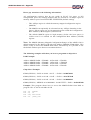
Example: This program shows how to access the MMCR PAR0 from DOS to
program CS1 as IOCS at 0100h–0107h
mov
mov
mov
mov
ax,
es,
eax,
es:
SSV EMBEDDED SYSTEMS
0FD00h
ax
28070100h
[88h],eax
51

























![hank yo_fo buyil_gaSamsung (}a_Te_a ]hs](http://vs1.manualzilla.com/store/data/005691502_1-2e8e29ffb67d0c8f7d0d701e3cb644b7-150x150.png)