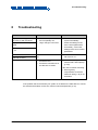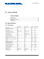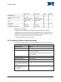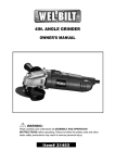
1
MP142E N-111 NEXLINE® Linear Actuator User Manual Version: 1.0.0 Date: 15.06.2015 This document describes the following products: N-111.201 NEXLINE®OEM Piezo Stepping Actuator, 10 mm, 50 N N-111.2A1 NEXLINE®OEM Piezo Stepping Actuator, 10 mm, 50 N, Linear Encoder, 5 nm Resolution Physik Instrumente (PI) GmbH & Co. KG, Auf der Roemerstr. 1, 76228 Karlsruhe, Germany Phone: +49 721 4846-0, Fax: +49 721 4846-1019, E-mail: [email protected] Physik Instrumente (PI) GmbH & Co. KG is the owner of the following trademarks: PI®, PIC®, PICMA®, PILine®, PIFOC®, PIMag®, PiezoWalk®, NEXACT®, NEXLINE®, NanoCube®, NanoAutomation®, Picoactuator®, PInano® The products described in this document are in part protected by the following patents: German patent no. 10148267B4 US patent no. 6,800,984B2 European patent no. 1267478B1 © 2015 Physik Instrumente (PI) GmbH & Co. KG, Karlsruhe, Germany. The text, photographs and drawings in this manual are protected by copyright. With regard thereto, Physik Instrumente (PI) GmbH & Co. KG retains all the rights. Use of said text, photographs and drawings is permitted only in part and only upon citation of the source. Original instructions First printing: 15.06.2015 Document number: MP142E, MMa, version 1.0.0 Subject to change without notice. This manual is superseded by any new release. The latest release is available for download (p. 3) on our website. Contents 1 About this Document 1.1 1.2 1.3 1.4 1.5 2 3 Goal and Target Audience of this User Manual ...................................................1 Symbols and Typographic Conventions ...............................................................1 Figures ..................................................................................................................2 Other Applicable Documents ................................................................................2 Downloading Manuals ..........................................................................................3 Safety 2.1 2.2 2.3 5 Intended Use ........................................................................................................5 General Safety Instructions ..................................................................................5 Organizational Measures ......................................................................................6 Product Description 3.1 3.2 3.3 3.4 3.5 3.6 1 7 Features and Applications ....................................................................................7 Model Overview ....................................................................................................8 Product View.........................................................................................................9 3.3.1 Overview .............................................................................................9 3.3.2 Product Details .................................................................................10 3.3.3 Product Labeling ...............................................................................11 Scope of Delivery ...............................................................................................12 Suitable Controllers ............................................................................................12 Only N-111.2A1: Technical Features for Closed-Loop Operation......................12 3.6.1 Linear Encoder (Sensor) ..................................................................12 3.6.2 Reference Point Switch ....................................................................12 4 Unpacking 13 5 Installation 15 5.1 5.2 5.3 5.4 5.5 Providing a Suitable Installation Environment ....................................................15 Mounting the N-111 ............................................................................................21 Connecting the N-111 to the Protective Earth Conductor ..................................22 Affixing the Load to the N-111 ............................................................................24 Connecting the N-111 to the Controller ..............................................................26 6 Start-Up and Operation 6.1 6.2 6.3 7 General Notes on Start-Up and Operation .........................................................27 Operating the N-111 ...........................................................................................29 Discharging the N-111 ........................................................................................30 Maintenance 7.1 7.2 27 31 General Notes on Maintenance ..........................................................................31 Cleaning the N-111 .............................................................................................31 8 Troubleshooting 33 9 Customer Service 35 10 Technical Data 37 10.1 10.2 10.3 10.4 10.5 Specifications......................................................................................................37 10.1.1 Data Table ........................................................................................37 10.1.2 Ambient Conditions and Classifications ...........................................38 Maximum Ratings ...............................................................................................39 Mechanical Load Capacity .................................................................................40 Dimensions .........................................................................................................42 10.4.1 N-111.201 .........................................................................................42 10.4.2 N-111.2A1 .........................................................................................43 Pin Assignment ...................................................................................................44 10.5.1 N-111.201 .........................................................................................44 10.5.2 N-111.2A1 .........................................................................................45 11 Old Equipment Disposal 47 12 EC Declaration of Conformity 49 1 About this Document 1 About this Document In this Chapter Goal and Target Audience of this User Manual ............................................................ 1 Symbols and Typographic Conventions ........................................................................ 1 Figures ........................................................................................................................... 2 Other Applicable Documents ......................................................................................... 2 Downloading Manuals ................................................................................................... 3 1.1 Goal and Target Audience of this User Manual This manual contains information on the intended use of the N-111. It assumes that the reader has a fundamental understanding of basic servo systems as well as motion control concepts and applicable safety procedures. The latest versions of the user manuals are available for download (p. 3) on our website. 1.2 Symbols and Typographic Conventions The following symbols and typographic conventions are used in this user manual: CAUTION Dangerous situation If not avoided, the dangerous situation will result in minor injury. Actions to take to avoid the situation. NOTICE Dangerous situation If not avoided, the dangerous situation will result in damage to the equipment. Actions to take to avoid the situation. N-111 NEXLINE® Linear Actuator MP142E Version: 1.0.0 1 1 About this Document INFORMATION Information for easier handling, tricks, tips, etc. Symbol/ Label Meaning 1. Action consisting of several steps whose sequential order must be observed 2. Action consisting of one or several steps whose sequential order is irrelevant List item p. 5 Cross-reference to page 5 RS-232 Labeling of an operating element on the product (example: socket of the RS-232 interface) Warning signs affixed to the product that refer to detailed information in this manual. 1.3 Figures For better understandability, the colors, proportions and degree of detail in illustrations can deviate from the actual circumstances. Photographic illustrations may also differ and must not be seen as guaranteed properties. 1.4 Other Applicable Documents The devices and software tools which are mentioned in this documentation are described in their own manuals. 2 Product Document E-712 Digital Piezo Controller PZ195E User Manual PIMikroMove SM148E Software Manual Version: 1.0.0 MP142E N-111 NEXLINE® Linear Actuator 1 About this Document 1.5 Downloading Manuals INFORMATION If a manual is missing or problems occur with downloading: Contact our customer service department (p. 35). INFORMATION For some products (e.g. Hexapod systems and electronics that are delivered with a CD), access to the manuals is password-protected. The password is stored on the CD. Availability of the manuals: Password-protected manuals: FTP download directory Follow the corresponding instructions for downloading. Freely available manuals: PI website Downloading freely accessible manuals 1. Open the website http://www.pi-portal.ws. 2. Click Downloads. 3. Click the corresponding product category. 4. Go to the corresponding product code. The available manuals are displayed. 5. Click the desired manual and save it on the hard disk of your PC or on a data storage medium. Downloading password-protected manuals 1. Insert the product CD in the PC drive. 2. Switch to the Manuals directory on the CD. 3. In the Manuals directory, open the Release News (file including releasenews in the file name). 4. Find the user name and the password in the section "User login for software download" in the Release News. 5. Open the FTP download directory (ftp://pi-ftp.ws). − Windows operating systems: Open the FTP download directory in Windows Explorer. N-111 NEXLINE® Linear Actuator MP142E Version: 1.0.0 3 1 About this Document 6. Log in with the user name and the password from the Release News. 7. In the directory of the corresponding product, go to the Manuals sub-directory. 8. Copy the desired manual to the hard disk of your PC or to a data storage medium. 4 Version: 1.0.0 MP142E N-111 NEXLINE® Linear Actuator 2 Safety 2 Safety In this Chapter Intended Use ................................................................................................................. 5 General Safety Instructions ........................................................................................... 5 Organizational Measures............................................................................................... 6 2.1 Intended Use Based on its design and realization, the N-111 is intended for single-axis positioning, adjusting and shifting of loads at various velocities. The N-111 is a laboratory device as defined by DIN EN 61010-1. It is intended to be used in interior spaces and in an environment which is free of dirt, oil, and lubricants. The intended use of the N-111 is only possible when installed and in connection with a suitable controller (p. 12). The controller is not included in the scope of delivery of the N-111. 2.2 General Safety Instructions The N-111 is built according to state-of-the-art technology and recognized safety standards. Improper use can result in personal injury and/or damage to the N-111. Only use the N-111 for its intended purpose, and only use it if it is in a good working order. Read the user manual. Immediately eliminate any faults and malfunctions that are likely to affect safety. The operator is responsible for the correct installation and operation of the N-111. N-111 NEXLINE® Linear Actuator MP142E Version: 1.0.0 5 2 Safety 2.3 Organizational Measures User manual Always keep this user manual available by the N-111. The latest versions of the user manuals are available for download (p. 3) on our website. Add all information given by the manufacturer to the user manual, for example supplements or Technical Notes. If you pass the N-111 on to other users, also turn over this user manual as well as other relevant information provided by the manufacturer. Only use the device on the basis of the complete user manual. Missing information due to an incomplete user manual can result in minor injury and property damage. Only install and operate the N-111 after having read and understood this user manual. Personnel qualification The N-111 may only be installed, started up, operated, maintained and cleaned by authorized and appropriately qualified personnel. 6 Version: 1.0.0 MP142E N-111 NEXLINE® Linear Actuator 3 Product Description 3 Product Description In this Chapter Features and Applications ............................................................................................. 7 Model Overview ............................................................................................................. 8 Product View ................................................................................................................. 9 Scope of Delivery ........................................................................................................ 12 Suitable Controllers ..................................................................................................... 12 Only N-111.2A1: Technical Features for Closed-Loop Operation............................... 12 3.1 Features and Applications Travel range 10 mm High push and holding forces (50 N / 70 N) High position resolution PiezoWalk® principle Self-locking, thus no holding currents and no heat generation at rest Non-magnetic function principle Can also be used in environments with: − Clean room requirements − Strong magnetic fields − Strong UV radiation − Vacuum (modified products up to 0.1 hPa, on request) The N-111 NEXLINE® OEM linear actuator is a compact drive for nanopositioning technology. The feed is generated by coordinated shearing and clamping motions of strongly preloaded piezo elements that are coupled to a rod (PiezoWalk® principle). In this way, NEXLINE® drives combine relatively long travel ranges with the nanometer precision of piezo actuators. The N-111.2A1 is equipped with a linear encoder for direct measurement of the rod position. The resolution here is 5 nm over the entire travel range (closed-loop operation). In highly dynamic analog operation, position resolutions up to 25 pm can be achieved (open-loop operation). N-111 NEXLINE® Linear Actuator MP142E Version: 1.0.0 7 3 Product Description The linear actuator supports the following modes of operation for positioning a load: Operating Mode Advantages Full step mode Long travel ranges Long travel ranges Travel ranges in the µm range Nanostepping mode Analog mode High velocity High dynamic forces Low vibration Uniformity of motion High dynamics High resolution Further details on the operating modes are found in the manual of the controller used. 3.2 Model Overview Two standard versions of the N-111 NEXLINE® OEM linear actuator are available. They differ regarding the presence of an integrated sensor and thus in height. Figure 1: Height hb 8 1 Actuator 2 Surface (part of the application) hb Height Version: 1.0.0 MP142E N-111 NEXLINE® Linear Actuator 3 Product Description Model Characteristics N-111.201 NEXLINE® OEM piezo stepping actuator, travel range 10 mm, max. push force 50 N, overall height hb 42.5 mm N-111.2A1 NEXLINE® OEM piezo stepping actuator, travel range 10 mm, max. push force 50 N, with linear encoder, 5 nm resolution, overall height hb 62 mm For further technical data, see the specifications (p. 37). PI also produces custom designs upon request. Custom designs can differ from the described standard products in respect to dimensions, characteristics or other technical data. If necessary, contact our customer service department (p. 35) directly. 3.3 Product View 3.3.1 Overview Figure 2: Linear actuators N-111.2A1 (left) and N-111.201 (right) N-111 NEXLINE® Linear Actuator MP142E Version: 1.0.0 9 3 Product Description 3.3.2 Product Details Figure 3: Position of important elements, top and bottom view of actuator case (schematic, components marked in color) 10 1 Connection cable 2 Protective earth connection 3 Rod (non-rotating) 4 Actuator case 5 Mounting plate Version: 1.0.0 MP142E N-111 NEXLINE® Linear Actuator 3 Product Description 3.3.3 Product Labeling Figure 4: Position and appearance of the product labels Position Labeling Description 1 Warning sign "Attention! Residual voltage" 2 Symbol for the protective earth conductor, marks the protective earth connection of the N-111 (p. 22) 3 N-111.2A1 Product name (example), the places after the point refer to the model 3 113055789 Serial number (example), individual for each N-111 Meaning of the places (counting from left): 1 = internal information, 2 and 3 = manufacturing year, 4 to 9 = consecutive numbers 3 Warning sign "Observe manual!" 3 Old equipment disposal (p. 47) 3 Country of origin: Germany Country of origin 3 WWW.PI.WS Manufacturer's address (website) 3 Manufacturer's logo 3 CE conformity mark N-111 NEXLINE® Linear Actuator MP142E Version: 1.0.0 11 3 Product Description 3.4 Scope of Delivery The N-111 is delivered with the following components: Order number Component N-111.2x1 Linear actuator according to order 000036450 M4 screw set for protective earth connection MP142E User manual (this document) in printed form Packaging materials 3.5 Suitable Controllers Controller Description E-712.1AM Digital Motion Controller, 1 Channel, for NEXLINE®Nanopositioning Linear Drives with Incremental Encoder 3.6 Only N-111.2A1: Technical Features for Closed-Loop Operation 3.6.1 Linear Encoder (Sensor) The linear actuator is equipped with an optical linear encoder. For the encoder resolution, refer to the table in the "Specifications" section (p. 37). Optical linear encoders measure the actual position directly (direct metrology). Therefore, errors occurring in the drivetrain, such as nonlinearity, backlash or elastic deformation, cannot influence the measurement of the position. 3.6.2 Reference Point Switch The linear actuator is equipped with a direction-sensing reference point switch that is located approximately in the middle of the travel range. This sensor transmits a TTL signal that indicates whether the linear actuator is on the positive or negative side of the reference point switch. The commands that use the reference signal are described in the user manual of the controller and/or in the corresponding software manuals. 12 Version: 1.0.0 MP142E N-111 NEXLINE® Linear Actuator 4 Unpacking 4 Unpacking 1. Unpack the N-111 with care. 2. Compare the contents against the items covered by the contract and against the packing list. 3. Inspect the contents for signs of damage. If parts are missing or you notice signs of damage, contact PI immediately. 4. Keep all packaging materials in case the product needs to be returned. N-111 NEXLINE® Linear Actuator MP142E Version: 1.0.0 13 5 Installation 5 Installation In this Chapter Providing a Suitable Installation Environment ............................................................. 15 Mounting the N-111 ..................................................................................................... 21 Connecting the N-111 to the Protective Earth Conductor ........................................... 22 Affixing the Load to the N-111 ..................................................................................... 24 Connecting the N-111 to the Controller ....................................................................... 26 5.1 Providing a Suitable Installation Environment Installation recommendation The N-111 is intended for being screwed into a level surface, a base body or a case (referred to in general as "surface" in the following). Alternatives for mounting holes (see also the following figures): Threaded holes in the surface Through holes in the surface The following instructions for preparing and carrying out the fastening refer to an installation with threaded holes. N-111 NEXLINE® Linear Actuator MP142E Version: 1.0.0 15 5 Installation If you use other designs, proceed correspondingly. Figure 5: Recommended fastening on the surface (cross sectional drawing, only one screw is screwed in for better representation) 16 1 Surface 2 Mounting plate of the linear actuator 3 Counterbore 4 Through hole for M3 (in the mounting plate of the linear actuator) 5 M3 threaded hole (in the surface) 6 Fastening screw: Cylinder head, M3 (ISO 4762) Version: 1.0.0 MP142E N-111 NEXLINE® Linear Actuator 5 Installation Figure 6: Example of alternative to recommended fastening (with through hole in the surface and nut) 1 Surface 2 Mounting plate of the linear actuator 3 Counterbore 4 Through hole for M3 (in t he mounting plate of the linear actuator) 5 Through hole for M3 (in the surface) 6 Fastening screw: Cylinder head, M3 (ISO 4762) 7 M3 nut N-111 NEXLINE® Linear Actuator MP142E Version: 1.0.0 17 5 Installation Providing a suitable installation environment Figure 7: Linear actuator on surface (schematic); relevant components 18 1 Surface (section) 2 M3 threaded hole 3 Case of the linear actuator 4 Feedthrough for rod (here: hole 10 mm coaxial to the motion axis of the rod) 5 Rod of the linear actuator Version: 1.0.0 MP142E N-111 NEXLINE® Linear Actuator 5 Installation Figure 8: Relevant rod dimensions d Diameter of the rod: 8 mm s Distance between rod end - lower edge of the mounting plate - with full use of the travel range: 3 mm to 13 mm, - at center position: 8 mm (delivery state, switching point for reference point switch in the N-111.2A1) x Motion axis of the rod You can obtain all dimensions of the linear actuator and relevant individual parts in the section "Dimensions" (p. 42). The intended use of the linear actuator requires a suitable installation environment. Make sure that the following conditions are met: − Material and statics of the surface and the screw connections (fastening screw / hole system) are designed so that the static and dynamic forces that occur can be safely and continuously managed. − Four M3 threaded holes and a feedthrough for the rod have been made in the surface. − The distances between the holes in the surface match the distances between the mounting holes of the linear actuator (dimensions see p. 42). − The depth of each hole is adapted to the length of the screws so that the linear actuator can be completely screwed in. N-111 NEXLINE® Linear Actuator MP142E Version: 1.0.0 19 5 Installation − The position and size of the feedthrough for the rod prevent the rod from touching the surface after mounting (position and dimensions of the rod see p. 42 and above figure). − The ambient conditions do not exceed the ranges that are given in the specification for the N-111 (see Technical Data (p. 37)). When planning the application and installing the linear actuator, take account of the space required for routing the cables without kinks and in accordance with regulations: − Length of the connection cable: approx. 1.5 m If necessary, provide measures to limit or compensate for undesirable forces and torques (example: gravity compensation in the case of vertical mounting). If possible, perform a graphic simulation of the intended actuator motions with a mounted load or suitable calculations, in order to identify possible collisions within the application. If necessary, implement suitable design- or control-related measures to avoid collisions during operation of the linear actuator. Example: Collisions of the load with the surface when the rod is moved inwards can be avoided by the following measures: − Spacers (flat washers or sleeves) between the rod and load − Reduced thickness of the surface − Limitation of the travel range in the PC software In accordance with legal regulations, avoid or label danger areas that result from installation of the linear actuator and from use (e.g., risk of crushing in the case of heavy moving loads, fast actuator motions and/or high drive torques). 20 Version: 1.0.0 MP142E N-111 NEXLINE® Linear Actuator 5 Installation 5.2 Mounting the N-111 INFORMATION For optimum repeatablity, all components must be firmly affixed to each other. Tools and accessories Four M3 cylinder head screws (ISO 4762) with suitable length Suitable screwdriver or hexagonal key Prerequisites You have provided a suitable installation environment (p. 15). The linear actuator is not connected to the controller. Mounting the N-111 Figure 9: Position of the mounting holes, schematic 1. Position the mounting holes in the mounting plate of the linear actuator (see figure) over the corresponding holes in the surface. 2. Completely screw in the cylinder head screws at all mounting holes. 3. Check that the linear actuator fits on the surface without backlash. N-111 NEXLINE® Linear Actuator MP142E Version: 1.0.0 21 5 Installation 5.3 Connecting the N-111 to the Protective Earth Conductor INFORMATION Observe the applicable standards for mounting the protective earth conductor. INFORMATION The hole for the protective earth connection is marked on the product p. 11. Tools and accessories Suitable protective earth conductor: conductor cross-section ≥ 0.75 mm , insulation green/yellow M4 screw set (included in the scope of delivery of the linear actuator) 2 Philips-head screwdriver (PH 2) Connecting the N-111 to the protective earth conductor Figure 10: Position of the protective earth connection 22 Version: 1.0.0 MP142E N-111 NEXLINE® Linear Actuator 5 Installation Figure 11: Mounting of protective earth connection (schematic) 1 M4 screw 2 Toothed washer 3 Flat washer 4 Cable lug 5 linear actuator case with protective earth connection (M4 threaded hole) and protective earth conductor symbol 6 Protective earth conductor 1. If necessary, fasten a suitable cable lug to the protective earth conductor. 2. Remove the screw, the toothed washers and flat washers from the package of the screw set. 3. As shown in the above figure: fasten one flat washer and one toothed washer each above and below the protective earth conductor or its cable lug with the screw on the protective earth connection of the linear actuator (position of the protective earth connection on the linear actuator: see figure above). 4. Tighten the screw with a torque of 1.2 Nm to 1.5 Nm. 5. Make sure that the protective earth conductor of the linear actuator is properly connected with the existing protective earth system within your application at all times. N-111 NEXLINE® Linear Actuator MP142E Version: 1.0.0 23 5 Installation 5.4 Affixing the Load to the N-111 NOTICE Impermissibly high load on the linear actuator Impermissibly high loads inhibit the motion of the rod and can damage or destroy the linear actuator. With respect to mass and fastening type of the load, observe the maximum permissible active and passive forces and the resulting torques that are allowed to act on the rod according to the specification (p. 37). INFORMATION For optimum repeatablity, all components must be firmly affixed to each other. Prerequisites You have properly fastened the linear actuator according to the corresponding instructions (p. 21). The linear actuator is not connected to the controller. Tools and accessories 24 M3 fastening screw with suitable length (depth of the threaded hole: 5 mm; further dimensions see p. 42). If necessary: Spring washer(s) or M3 flat washer(s) Open-end wrench, AF 7 Suitable screwdriver, hexagonal key or open-end wrench for the fastening screw Version: 1.0.0 MP142E N-111 NEXLINE® Linear Actuator 5 Installation Affixing load to the N-111 Figure 12: Relevant components of the rod for affixing the load 1 Wrench flat* of the rod 2 M3 threaded hole for affixing the load * There is a further, parallel wrench flat on the rod that is symmetrical to the threaded hole and at a distance of 7 mm from the wrench flat shown (hidden in the above view). 1. Attach the rod: Apply the open-end wrench to the wrench flats of the rod. 2. Affix the load on the threaded hole in the rod of the linear actuator with the fastening screw and, if necessary, attached spacers, safety washers or spring washers: Screw in the screw until you feel a resistance and tighten the screw with a torque of 1.1 Nm. 3. Check that the load is affixed firmly. N-111 NEXLINE® Linear Actuator MP142E Version: 1.0.0 25 5 Installation 5.5 Connecting the N-111 to the Controller Figure 13: Cabling diagram Prerequisites You have mounted the linear actuator properly (p. 15) and have connected the protective earth conductor (p. 22). You have installed a suitable controller (p. 12). You have read and understood the user manual of the controller. Connecting the N-111 to the controller 1. Connect the connector of the linear actuator to the corresponding socket of the controller (see user manual of the controller). 2. Secure the connection with the integrated screws against accidental disconnection. 3. Eliminate or label resulting danger areas in accordance with the valid regulations and recommendations. 26 Version: 1.0.0 MP142E N-111 NEXLINE® Linear Actuator 6 Start-Up and Operation 6 Start-Up and Operation In this Chapter General Notes on Start-Up and Operation .................................................................. 27 Operating the N-111 .................................................................................................... 29 Discharging the N-111 ................................................................................................. 30 6.1 General Notes on Start-Up and Operation CAUTION Risk of electric shock if the protective earth conductor is not connected! If a protective earth conductor is not or not properly connected, dangerous touch voltages can occur on the N-111 in the case of malfunction or failure of the system. If touch voltages exist, touching the N-111 can result in minor injuries from electric shock. Connect the N-111 to a protective earth conductor before start-up (p. 22). Do not remove the protective earth conductor during operation. If the protective earth conductor has to be removed temporarily (e. g. in the case of modifications), reconnect the N-111 to the protective earth conductor before starting it up again. N-111 NEXLINE® Linear Actuator MP142E Version: 1.0.0 27 6 Start-Up and Operation CAUTION Dangerous voltage and residual charge on piezo actuators! The N-111 is driven by piezo actuators. Temperature changes and compressive stresses can induce charges in piezo actuators. After being disconnected from the electronics, piezo actuators can also stay charged for several hours. Touching or short-circuiting the contacts in the connector of the N-111 can lead to minor injuries. In addition, the piezo actuators can be destroyed by an abrupt contraction. Do not open the N-111. Do not touch the contacts in the connector of the linear actuator. Secure the connector of the linear actuator with screws against being pulled out of the controller. If you want to pull out the connector of the linear actuator: Do not pull out the connector from the controller during operation. Discharge the linear actuator before pulling out the connector (p. 30). If possible: Switch off the controller and wait at least 10 seconds before pulling out the connector. NOTICE Heating up of the N-111 during operation! The heat produced during operation of the N-111 can affect your application. Install the N-111 so that your application is not affected by the dissipating heat. NOTICE Uncontrolled oscillation! Your application and the N-111 can be damaged by uncontrolled oscillations. Uncontrolled oscillations can be identified by the fact that the linear actuator approaches the target position too slowly or too fast or does not keep it stable (servo jitter). If uncontrolled oscillations occur during the operation of the N-111: 28 Immediately switch off the servo-control system of the affected axis. Check the settings of the servo-control parameters. Version: 1.0.0 MP142E N-111 NEXLINE® Linear Actuator 6 Start-Up and Operation NOTICE Increased friction due to lateral forces on the rod! Lateral forces that act on the rod of the N-111 increase the friction between the rod and internal drive components. Increased friction impairs the motion of the rod and increases the wear of the drive components. Avoid lateral forces on the rod of the N-111. INFORMATION For sending commands to the linear actuator, the outward motion of the rod is defined as positive direction of motion. INFORMATION In the ideal application case, the linear actuator is operated quasi-statically. In quasistatic operation, the load is mainly kept at a particular position and only temporarily positioned (stepping mode). For the N-111.2A1, the following also applies: INFORMATION The repeatability of the positioning is only ensured when the reference point switch is always approached from the same side. Recommended controllers from PI fulfill this requirement with their automatic direction detection for reference moves to the reference point switch. 6.2 Operating the N-111 Prerequisites You have read and understood the user manual of the controller. You have read and understood the user manual of the PC software. You have properly mounted the linear actuator (p. 15) and connected the protective earth conductor (p. 22). The controller and the required PC software have been installed. All connections with the controller have been established (see user manual of the controller). N-111 NEXLINE® Linear Actuator MP142E Version: 1.0.0 29 6 Start-Up and Operation Operating the N-111 Follow the instructions in the manual of the controller used for startup and operation of the N-111. 6.3 Discharging the N-111 The N-111 must be discharged in the following cases: When the N-111 is not used but the controller remains switched on to ensure temperature stability Before pulling out the connector of the N-111 (e. g. before demounting (e.g. before cleaning and transport of the N-111 and for modifications of the application) Discharging the N-111 1. If you are working in closed-loop operation: Switch off the servo mode on the controller. 2. Set the piezo voltage to 0 V on the controller. 3. If you want to disconnect the N-111 from the controller: 30 − If possible: Switch off the controller. − Wait at least 10 seconds before disconnection Version: 1.0.0 MP142E N-111 NEXLINE® Linear Actuator 7 Maintenance 7 Maintenance In this Chapter General Notes on Maintenance ................................................................................... 31 Cleaning the N-111 ...................................................................................................... 31 7.1 General Notes on Maintenance NOTICE Damage due to improper maintenance! The linear actuator can become misaligned as a result of improper maintenance. The specifications can change as a result (p. 37). Only loosen screws according to the instructions in this manual. 7.2 Cleaning the N-111 Prerequisites You have discharged the piezo actuators of the N-111 (p. 30). You have disconnected the N-111 from the controller. Cleaning the N-111 Clean the surfaces of the N-111 with a cloth that is slightly dampened with a mild cleanser or disinfectant (e.g. ethanol or isopropanol). Do not do any ultrasonic cleaning. N-111 NEXLINE® Linear Actuator MP142E Version: 1.0.0 31 8 Troubleshooting 8 Troubleshooting Problem Possible Causes Solution Target position is approached too slowly or with overshoot Servo-control parameters are not optimally set 1. Switch off the servo-control system immediately. Target position is not kept stable Large changes in the load 2. Check the settings of the servo-control parameters. 3. If necessary, correct the settings of the servo-control parameters. Uncontrolled oscillations of the N-111 Increased wear Reduced accuracy No or limited motion Excessive lateral forces on the rod Avoid lateral forces on the rod of the N-111. Reduce the load (see "Mechanical Load Capacity" (p. 40)). Excessive load Excessive counterforces in the direction of motion In the case of vertical mounting: Ensure gravity compensation so that the maximum load (p. 40) is not exceeded. If the problem that occurred with your system is not listed in the table above or cannot be solved as described, contact our customer service department (p. 35). N-111 NEXLINE® Linear Actuator MP142E Version: 1.0.0 33 9 Customer Service 9 Customer Service For inquiries and orders, contact your PI sales engineer or send us an e-mail (mailto:[email protected]). If you have questions concerning your system, have the following information ready: − Product codes and serial numbers of all products in the system − Firmware version of the controller (if present) − Version of the driver or the software (if present) − Operating system on the PC (if present) If possible: Take photographs or make videos of your system that can be sent to our customer service department if requested. The latest versions of the user manuals are available for download (p. 3) on our website. N-111 NEXLINE® Linear Actuator MP142E Version: 1.0.0 35 10 Technical Data 10 Technical Data In this Chapter Specifications .............................................................................................................. 37 Maximum Ratings ........................................................................................................ 39 Mechanical Load Capacity .......................................................................................... 40 Dimensions .................................................................................................................. 42 Pin Assignment ............................................................................................................ 44 10.1 Specifications 10.1.1 Data Table N-111.201 N-111.2A1 X X Travel range 10 10 Step size (in step mode) 10 nm to 7 µm 10 nm to 7 µm Travel range in analog mode ±2 ±2 Integrated sensor – Linear encoder Open-loop resolution 0.025 0.025 Closed-loop resolution – 5 nm Velocity (10 % duty cycle, full step mode)* 1.0 Velocity (100 % duty cycle, full step mode)* Velocity (100 % duty cycle, nanostepping mode)** Active axes Unit Tolerance Motion and positioning mm µm nm typ. 1.0 mm/s max. 0.6 0.6 mm/s max. 0.4 0.4 mm/s max. Stiffness in motion direction 16 16 N/µm ±20 % Drive force (active)*** 50 50 N max. Holding force (passive) 70 70 N min. Motor type NEXLINE® NEXLINE® Operating voltage ±250 ±250 Mechanical properties Drive properties N-111 NEXLINE® Linear Actuator MP142E V Version: 1.0.0 37 10 Technical Data N-111.201 N-111.2A1 Unit Operating temperature range -40 to 80 -40 to 80 °C Material Aluminum, stainless steel, titanium Aluminum, stainless steel, titanium Mass 245 325 g Cable length 1.5 1.5 m Connector Sub-D 25 Sub-D 25 Recommended controllers E-712.1AM E-712.1AM Tolerance Miscellaneous ±10 mm Ask about custom designs! * Depending on drive electronics.Data refer to operation with E-712 controller ** Depending on drive electronics.Data refer to operation with E-712 controller. The maximum velocity in nanostepping mode is designed for the best possible constancy so that no velocity variations occur when executing the steps. *** Data refer to operation in full step mode. 10.1.2 Ambient Conditions and Classifications The following ambient conditions and classifications must be observed for the N-111: Area of application For indoor use only Maximum altitude 2000 m Air pressure 1100 hPa to 0.1 hPa Relative humidity Highest relative humidity 80% for temperatures to 31°C, non-condensing Decreasing linearly to 50% relative humidity at 40 °C, non-condensing 38 Operating temperature -40°C to 80°C Storage temperature -40°C to 80°C Transport temperature -40°C to 80°C Overvoltage category (in acc. with EN 60664-1:2007 / VDE 0110-1) II Protection class (acc. to EN 61140 / VDE 0140-1) I Version: 1.0.0 MP142E N-111 NEXLINE® Linear Actuator 10 Technical Data Degree of pollution (acc. to EN 60664-1:2007 / VDE 0110-1) 1 Degree of protection (acc. to IEC 60529) IP20 10.2 Maximum Ratings The N-111 is designed for the following maximum ratings: Operating Mode Maximum Operating Maximum operating Voltage frequency or velocity (unloaded) Maximum power consumption* Analog mode +250 V; -250 V 700 Hz 1.65 W** Full step mode 600 µm/s 2.6 W Nanostepping mode 400 µm/s * for dynamic continuous operation (not recommended!) ** at full amplitude and a max. frequency of 250 Hz N-111 NEXLINE® Linear Actuator MP142E Version: 1.0.0 39 10 Technical Data 10.3 Mechanical Load Capacity Maximum values for torque and forces Negative values in the table correspond to a reversal of the effective direction according to the following figure. Parameter Permissible Values Passive force (holding force, linear actuator currentless) Fh - 70 N to 70 N Active force (drive force) Fp - 50 N to 50 N Lateral force Fl - 5 N to 5 N Torque Mrot in the direction of the rod axis - 0.2 Nm to 0.2 Nm Torque Ml generated by lateral force (radial; not shown) - 0.15 Nm to 0.15 Nm The following figure shows the directions of acting forces and torques as examples. Depending on the orientation of the setup, effects of gravity must be included in the calculation. Figure 14: Forces and torques potentially affecting the rod (schematic) Fp: Active force (direction for forward motion of the rod) or Fh: Holding force (when the rod is at rest) F: Force generated by load (positioning or holding) Fl: Lateral force Mrot: Torque (e.g. in the case of load mounting; dashed: direction of action of the causal force) 40 Version: 1.0.0 MP142E N-111 NEXLINE® Linear Actuator 10 Technical Data Velocities and step sizes when the drive is loaded Figure 15: Velocity v as a function of the active force Fp (qualitative) Fp: Active force v: Velocity of the rod Special conditions: A: No load B: Stop C: Slippage With increasing mass of the load (and thus the active force to be generated), the achievable step size of the drive elements and thus also the maximum velocity of the rod decrease (see explanations of the operation of the NEXLINE drive in the manual of the controller). The relationships are qualitatively shown in the above diagram. In the unloaded state (point A), maximum step size and velocity are attained for horizontal mounting of linear actuator and load when no pull force acts in the direction of the rod axis. Pull forces acting on the rod (e.g. gravity in the case of vertical mounting or, in relation to the horizontal line, inclined mounting of the system) can support the rod motion and cause the velocity to increase further (area left of point A). On the contrary, the linear actuator applies the maximum active force to compensate for the maximum permissible load (point B). In this state, the velocity drops to 0. In the currentless state of the linear actuator, the rod is clamped (holding force; generated by the preloaded piezo assemblies). Consequently, the position of a coupled load is held with a permissible load. If the holding force is overcompensated by an impermissibly high load, the clamping effect of the piezo assemblies on the rod is lost (slippage, point C). Compared to the velocity, analog conditions result for the step sizes in normal operation (see graph, range to the left of B). N-111 NEXLINE® Linear Actuator MP142E Version: 1.0.0 41 10 Technical Data 10.4 Dimensions 10.4.1 N-111.201 Dimensions in mm. Note that the decimal places are separated by a comma in the drawings. Figure 16: N-111.201 dimensions, rod at center position 42 Version: 1.0.0 MP142E N-111 NEXLINE® Linear Actuator 10 Technical Data 10.4.2 N-111.2A1 Dimensions in mm. Note that the decimal places are separated by a comma in the drawings. Figure 17: N-111.2A1 dimensions, rod at center position N-111 NEXLINE® Linear Actuator MP142E Version: 1.0.0 43 10 Technical Data 10.5 Pin Assignment 10.5.1 N-111.201 Figure 18: Sub-D 25 connector Pin Signal* Function Direction 1 D1+ Supply voltage for shearing group 1 (-250 V to 250 V) Input 2 - 3 - 4 D2+ Supply voltage for shearing group 2 (-250 V to 250 V) Input 5 - 6 - 7 - 8 - 9 - 10 C+ Supply voltage for clamping group (-250 V to 250 V) Input 11 - 12 - 13 - 14 - 15 D1- 16 - 17 - 18 D2- 19 - 44 Ground of shearing group 1 Ground of shearing group 2 Version: 1.0.0 MP142E N-111 NEXLINE® Linear Actuator 10 Technical Data Pin Signal* 20 - 21 - 22 - 23 - 24 C- 25 - Function Direction Ground of clamping group * The "-" sign indicates that the corresponding pin has not been assigned. 10.5.2 N-111.2A1 Figure 19: Sub-D 25 connector Pin Signal* Function Direction 1 D1+ Supply voltage for shearing group 1 (-250 V to 250 V) Input 2 +5V (sensor) Supply voltage for encoder Input 3 +5V (ref) Supply voltage for reference point switch Input 4 D2+ Supply voltage for shearing group 2 (-250 V to 250 V) Input 5 - 6 - 7 - 8 GND (sensor) Encoder ground 9 GND (ref) Ground of reference point switch 10 C+ Supply voltage for clamping group (-250 V to 250 V) N-111 NEXLINE® Linear Actuator MP142E Input Version: 1.0.0 45 10 Technical Data Pin Signal* Function Direction 11 - 12 Ref- Reference point switch Output 13 Ref+ Reference point switch Output 14 - 15 D1- Ground of shearing group 1 16 Sin+ Encoder signal 1 (sine) Output 17 Sin- Encoder signal 1 (sine) Output 18 D2- Ground of shearing group 2 19 Cos+ Encoder signal 2 (cosine) Output 20 Cos- Encoder signal 2 (cosine) Output 21 - 22 - 23 - 24 C- 25 - Ground of clamping group * The "-" sign indicates that the corresponding pin has not been assigned. 46 Version: 1.0.0 MP142E N-111 NEXLINE® Linear Actuator 11 Old Equipment Disposal 11 Old Equipment Disposal In accordance with EU law, electrical and electronic equipment may not be disposed of in EU member states via the municipal residual waste. Dispose of your old equipment according to international, national, and local rules and regulations. In order to fulfil its responsibility as the product manufacturer, Physik Instrumente (PI) GmbH & Co. KG undertakes environmentally correct disposal of all old PI equipment made available on the market after 13 August 2005 without charge. Any old PI equipment can be sent free of charge to the following address: Physik Instrumente (PI) GmbH & Co. KG Auf der Roemerstr. 1 D-76228 Karlsruhe, Germany N-111 NEXLINE® Linear Actuator MP142E Version: 1.0.0 47 12 EC Declaration of Conformity 12 EC Declaration of Conformity For the N-111, an EC Declaration of Conformity has been issued in accordance with the following European directives: 2006/95/EC, Low Voltage Directive 2004/108/EC, EMC Directive 2011/65/EU, RoHS Directive The applied standards certifying the conformity are listed below. Safety (Low Voltage Directive): EN 61010-1:2010 EMC: EN 61326-1:2013 RoHS: EN 50581:2012 N-111 NEXLINE® Linear Actuator MP142E Version: 1.0.0 49