1
ESTUN
AC Servo Drive
PRONET User Manual
www.estun-servo.com
Product Line-up
Servo motor
Series
Power
Model
200V
200W
EMJ-02APA
PRONET-02A□A
400W
EMJ-04APA
PRONET-04A□A
750W
EMJ-08APA
PRONET-08A□A
1000W
EMJ-10APA
PRONET-10A□A
1.0kW
EMG-10A□A
PRONET-10A□A
1.5kW
EMG-15A□A
PRONET-15A□A
2.0kW
EMG-20A□A
PRONET-20A□A
3.0kW
EMG-30A□A
PRONET-30A□A
5.0kW
EMG-50A□A
PRONET-50A□A
EML
1.0kW
EML-10A□A
PRONET-10A□A
1000min-1
2.0kW
EML-20A□A
PRONET-20A□A
3.0kW
EML-30A□A
PRONET-30A□A
4.0kW
EML-40A□A
PRONET-50A□A
EMB
7.5kW
EMB-75D□A
PRONET-75D□A
1500min-1
11kW
EMB-1AD□A
PRONET-1AD□A
15kW
EMB-1ED□A
PRONET-1ED□A
Small
capacity
EMJ
3000min
-1
EMG
Large
capacity
Medium capacity
2000min
Medium inertia
Servo drive
-1
400V
ESTUN Servo Motor
series
■ Fetures
● Medium inertia
● Instantaneous peak torque
(300% of rated torque)
● Wide selection: 200W to 1000W, holding
brake options
● Maximum speed: 4500r/min
● Mounted 2500P/R incremental encoder,
Optional mounted 17-bit absolute encoder
■
●
●
●
●
●
●
Application Examples
Chip mounters
PCB drilling stations
Robots
Material handling machines
Food processing equipment
Textile machines
■
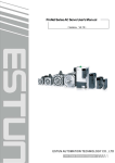
Model Designations
EMJ
–
08
ESTUN servo motor
A
P
A
【1+2】
1
【3】
【4】
1
【5】
【6】
【7】
EMJ series
【1+2】Rated output power
Code
Specifications
02
200W
04
400W
08
750W
10
1000W
【3】Power supply voltage
Code
Specifications
A
200VAC
【4】Encoder
Code
Specifications
P
Increamental
wire-saving encoder :
2500P/R
S
17digit
absolute :
131072P/R
【5】Design revision order
Code
A
Specifications
Design revision order
【6】Shaft end
Code
Specifications
1
Straight without key
(standard)
2
Straight with key and
tap
【7】Options
Code
Specifications
1
Without options
2
With oil seal
3
With
holding
brake(DC24V)
With oil seal and
holding brake(DC24V)
4
ESTUN Servo motor
■ Ratings and specifications
Voltage
200VAC
Servomotor model
EMJ-
Rated output power
W
200
Rated torque
N·m
0.64
N·m
1.91
Arms
Arms
Instantaneous
Torque
Peak
Rated Current
Instantaneous
Current
Max.
Rated Speed
04□PA
08A□A
10A□A
400
750
1000
1.27
2.39
3.18
3.82
7.16
9.55
1.3
2.7
4.0
5.3
3.9
8.1
12.0
15.9
1.48
1.89
min-1
3000
-1
Max. Speed
min
Rotor Moment of Inertia
x10-4kg·m2
Encoder
02A□A
4500
0.19
0.32
Standard
Increamental wire-saving:2500P/R
Option
17 digit absolute:131072P/R
Insulation Class
B
Ambient Temperature
0 to +40℃ (non freezing)
Ambient Humidity
20 to 80% RH (non condensing)
Enclosure
Totally enclosed, self-cooled, IP55 (except for shaft opening and connectors)
Vibration
49m/s2
●
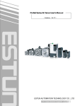
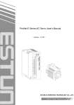
Torque-Motor Speed Characteristics (A:Continuous Duty Zone,B:Intermittent Duty Zone)
ESTUN Servo motor
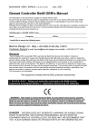
■ Dimension mm
Model
EMJ-
L
LL
02APA
153
04APA
08APA
10APA
Flange face
Tap×
Depth
QK
QL
W
T
U
5.5
14
M5x10L
16
4
5
5
3
50
5.5
14
M5x10L
16
4
5
5
3
70
6
19
M6x15L
22
4
6
6
3.5
70
6
19
M6x15L
22
4
6
6
3.5
LE
LF
LC
LA
LB
LZ
123
30
3
6
60
70
50
183
153
30
3
6
60
70
191
156
35
3
10
80
90
211
176
35
3
10
80
90
● Motor connector specification
connector:172167-1 (AMP)
pin:
Pin
No.
1
2
3
4
170360-1 (AMP)
Signal
U
phase
V
phase
W
phase
FG
Color
red
blue
white
Green/yellow
● Encoder connector specification
connector:172169-1 (AMP)
pin:
170359-3 (AMP)
Increamental wire-saving
Pin
No.
1
17 digit absolute
A+
blue
Pin
No.
1
2
B+
green
2
3
C+
yellow
3
—
—
4
A-
Blue/black
4
BAT+
brown
5
B-
Green/black
5
BAT-
Brown/black
6
C-
Yellow/black
6
—
—
7
PG5V
red
7
PG5V
red
8
PG0V
black
8
PG0V
black
9
FG
shield
9
FG
shield
Signal
Color
Key
S
LR
Signal
Color
S+
blue
S-
Blue/black
ESTUN Servo motor
series
■ Features
● High-speed driving of feed shafts for
various
● Wide Selection: 1.0kW to 5.0kW, holding
brake options
● Mounted wire-saving encoder(2500P/R)
Optionalmounted 17-bit serial encoder
● Protective Structure: IP65
■
●
●
●
●
Application Examples
Machine tools
Material handling machines
Food processing equipment
Textile machines
■ Model Designations
EMG
–
ESTUN servo motor
10
A
【1+2】
P
【3】
A
【4】
1
【5】
1
【6】
【7】
EMG series
【1+2】rated output power
Code
Specification
10
1.0kW
15
1.5kW
20
2.0kW
30
3.0kW
50
5.0kW
【3】power supply voltage
Code
Specification
A
200VAC
【4】encoder
Code
Specification
P
Increamental
wire-saving encoder :
2500P/R
S
17-bit
absolute
encoder:131072P/R
【5】design revision order
Code
A
Specification
Design revision order
【6】shaft end
Code
Specification
1
Straight without key
(standard)
2
Straight with key and
【7】options
Code
Specification
1
Without option
2
With oil seal
3
With
holding
brake
(DC24V)
With oil seal and
holding brake(DC24V)
4
tap
ESTUN Servo motor
■ Ratings and Specifications
Voltage
200VAC
Servo motor Model
EMG-
Rated output power
kW
1.0
1.5
2.0
3.0
5.0
Rated torque
N·m
4.78
7.16
9.55
14.3
23.9
N·m
14.3
21.5
28.7
43.0
71.6
Arms
6.0
9.0
12.0
18.0
28.0
Arms
18.0
27.0
36.0
54.0
84.0
Instantaneous
Torque
Peak
Rated Current
Instantaneous
Current
Max.
Rated Speed
15A□A
min-1
min
Rotor Moment of Inertia
x10-4kg·m2
20A□A
30A□A
50A□A
2000
-1
Max. Speed
Encoder
10A□A
3000
9.43
13.7
Standard
Increamantal wire-saving:2500P/R
Option
17-bit absolute:131072P/R
18.0
Insulation Class
Ambient Temperature
Ambient Humidity
Enclosure
Vibration
●
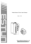
Torque-Motor Speed Characteristics (A:Continuous Duty Zone, B:Intermittent Duty Zone)
ESTUN Servo motor
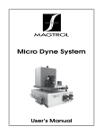
■ Dimensions mm
Model
EMG-
L
LL
KB1
KB2
KL1
KL2
10A□A
215
160
84
135
118
15A□A
240
185
109
160
20A□A
265
210
134
30A□A
307
228
50A□A
347
268
Flange face
Key
S
Tap×
Depth
QK
QL
W
T
U
9
22
M6x20L
40
5
8
7
4
110
9
22
M6x20L
40
5
8
7
4
145
110
9
22
M6x20L
40
5
8
7
4
180
200
114.3
13.5
35
M8x16L
55
6
10
8
5
180
200
114.3
13.5
35
M8x16L
55
6
10
8
5
LR
LE
LF
LC
LA
LB
LZ
79
55
4
12
130
145
110
118
79
55
4
12
130
145
185
118
79
55
4
12
130
143
203
140
79
79
3.2
18
183
243
140
79
79
3.2
18
● Motor receptacle specification
receptacle:MS3102A20-4P (EMG-10A/15A/20A);MS3102A22-22P (EMG-30A/50A)
connector:MS3108B20-4S (EMG-10A/15A/20A);MS3108B22-22S (EMG-30A/50A)
cable clamp:MS3057-12A
Pin
A
B
C
D
Signal
U
phase
V
phase
W
phase
FG
Color
red
blue
white
Green/yellow
● Encoder receptacle specification
receptacle:MS3102A20-29P
connector:MS3108B20-29S
cable clamp:MS3057-12A
Increamental wire-saving encoder
code
signal
A
B
C
D
17-bit absolute
color
code
signal
color
code
signal
color
code
signal
color
A+
blue
K
—
—
A
—
—
K
S+
blue
A-
Blue/black
L
—
—
B
—
—
L
S-
Blue/black
B+
green
M
—
—
C
—
—
M
—
—
B-
Green/black
N
—
—
D
—
—
N
—
—
E
C+
yellow
P
—
—
E
—
—
P
—
—
F
C-
Yellow/black
R
—
—
F
—
—
R
—
—
G
PG0V
black
S
—
—
G
PG0V
black
S
BAT-
Yellow/black
H
PG5V
red
T
—
—
H
PG5V
red
T
BAT+
yellow
J
FG
shield
—
—
—
J
FG
shield
—
—
—
ESTUN Servo motor
series
■ Features
● High-speed driving of feed shafts for
various
● Wide Selection: 1.0kW to 5.0kW, holding
brake options
● Mounted 2500P/R incremental encoder,
Optional mounted 17-bit serial encoder
● Protective Structure: IP65
■Application Examples
●
●
●
●
Machine tools
Material handling machines
Food processing equipment
Textile machines
■ Model Designation
EML
–
ESTUN servo motor
10
A
【1+2】
P
【3】
A
【4】
1
【5】
1
【6】
【7】
EML series
【1+2】rated output power
code
Specification
10
1.0kW
20
2.0kW
30
3.0kW
40
4.0kW
【3】power supply voltage
code
Specification
A
200VAC
【4】encoder
code
Specification
P
Increamental
wire-saving:2500P/R
S
17-bit
absolute :
131072P/R
【5】design revision order
code
A
Specification
Design revision order
【6】shaft end
code
Specification
1
Straight without key
(standard)
2
Straight with key and
tap
【7】option
code
Specification
1
Without option
2
With oil seal
3
With
holding
brake
(DC24V)
With oil seal and
holding brake(DC24V)
4
ESTUN Servo motor
■ Ratings and specification
voltage
200VAC
Servo motor Model
EML-
Rated output power
kW
1.0
2.0
3.0
4.0
Rated torque
N·m
9.55
19.1
28.7
38.2
N·m
28.7
57.3
86.0
114.6
Arms
6.0
12.0
18.0
24.0
Arms
18.0
36.0
54.0
72.0
Instantaneous
Torque
Peak
Rated Current
Instantaneous
Current
Max.
Rated Speed
20A□A
min-1
min
Rotor Moment of Inertia
x10-4kg·m2
30A□A
40A□A
1000
-1
Max. Speed
Encoder
10A□A
1500
18.0
Standard
Increamental wire-saving:2500P/R
Option
17-bit absolute:131072P/R
Insulation Class
F
Ambient Temperature
0 to +40℃ (non freezing)
Ambient Humidity
20 to 80% RH (non condensing)
Enclosure
Totally enclosed, self-cooled, IP55 (except for shaft opening and connectors)
Vibration
24.5m/s2
Torque-Motor Speed Characteristics (A:Continuous Duty Zone, B:Intermittent Duty Zone)
ESTUN Servo motor
■ Dimention mm
Model
EML-
L
LL
KB1
KB2
KL1
KL2
10A□A
265
210
134
185
118
20A□A
332
253
168
228
30A□A
372
293
208
40A□A
412
333
248
Flange face
key
S
Tap×
Depth
QK
QL
W
T
9
22
M6x20L
40
5
8
7
4
114.3
13.5
35
M8x16L
55
6
10
8
5
200
114.3
13.5
35
M8x16L
55
6
10
8
5
200
114.3
13.5
35
M8x16L
55
6
10
8
5
LR
LE
LF
LC
LA
LB
LZ
79
55
4
12
130
145
110
140
79
79
3.2
18
180
200
268
140
79
79
3.2
18
180
308
140
79
79
3.2
18
180
U
● Motor receptacle specification
receptacle:MS3102A20-4P (EML-10A);MS3102A22-22P (EML-20A/30A/40A)
connector:MS3108B20-4S (EML-10A);MS3108B22-22S (EML-20A/30A/40A)
cable clamp:MS3057-12A
code
A
B
C
D
signal
U
phase
V
pahse
W
phase
FG
color
red
blue
white
Green/black
● Encoder receptacle specification
receptacle:MS3102A20-29P
connector:MS3108B20-29S
cable clamp:MS3057-12A
Increamental wire-saving encoder
17-bit absolute
code
signal
color
code
signal
color
code
signal
color
code
signal
A
A+
blue
K
—
—
A
—
—
K
S+
color
blue
B
A-
Blue/black
L
—
—
B
—
—
L
S-
Blue/black
C
B+
green
M
—
—
C
—
—
M
—
—
D
B-
Green/black
N
—
—
D
—
—
N
—
—
E
C+
yellow
P
—
—
E
—
—
P
—
—
F
C-
Yellow/black
R
—
—
F
—
—
R
—
—
G
PG0V
black
S
—
—
G
PG0V
black
S
BAT-
Yellow/black
H
PG5V
red
T
—
—
H
PG5V
red
T
BAT+
yellow
J
FG
shield
—
—
—
J
FG
shield
—
—
—
ESTUN Servo motor
series
■ Features
● Power supply voltage 400V
● Driving of feed shafts for various
● Wide Selection: 1.0kW to 5.0kW, holding
brake options
● Mounted 2500P/R incremental encoder,
Optional mounted 17-bit serial encoder
● Protective Structure: IP65
■Application Examples
●
●
●
●
Machine tools
Material handling machines
Food processing equipment
Textile machines
■ Model Designation
EMB
–
ESTUN servo motor
1E
D
【1+2】
P
【3】
A
【4】
1
【5】
1
【6】
【7】
EMB series
【1+2】rated output power
code
Specification
75
7.5kW
1A
11.0kW
1E
15.0kW
【4】encoder
code
Specification
P
Increamental
wire-saving encoder :
2500P/R
S
17-bit
absolute
encoder:131072P/R
【5】design revision order
【3】power supplu voltage
code
Specification
D
400VAC
code
A
Specification
design revision order
【6】shaft end
code
Specification
1
Straight without key
(standard)
2
Straight with key and
tap
【7】option
code
Specification
1
Without option
2
With oil seal
3
With
holding
brake
(DC24V)
With oil seal and
holding brake(DC24V)
4
ESTUN Servo motor
■ Ratings and specifications
voltage
200VAC
Servo motor Model
EMB-
Rated output power
kW
7.5
11.0
15.0
Rated torque
N·m
47.8
70.0
95.5
N·m
119.4
175
191
Arms
18.0
28.0
38.0
Arms
56.0
70.0
84.0
Instantaneous
Torque
Peak
Rated Current
Instantaneous
Current
Max.
Rated Speed
1AD□A
min-1
1500
-1
2000
Max. Speed
min
Rotor Moment of Inertia
x10-4kg·m2
Encoder
75D□A
standard
Increamental wire-saving:2500P/R
option
17-bit absolute:131072P/R
1ED□A
Insulation Class
F
Ambient Temperature
0 to +40℃ (non freezing)
Ambient Humidity
20 to 80% RH (non condensing)
Enclosure
Totally enclosed, self-cooled, IP55 (except for shaft opening and connectors)
Vibration
24.5m/s2
●
Torque-Motor Speed Characteristics (A:Continuous Duty Zone, B:Intermittent Duty Zone)
ESTUN Servo motor
■ Dimention mm
model
EMB-
L
LL
KB1
KB2
KL1
KL2
Flange face
key
S
Tap×
Depth
QK
QL
W
T
U
13.5
42
M16×32
100
5
12
8
5
200
13.5
42
M16×32
100
5
12
8
5
200
13.5
42
M16×32
100
5
12
8
5
LR
LE
LF
LC
LA
LB
LZ
75D□A
116
4
18
220
235
200
1AD□A
116
4
18
220
235
1ED□A
116
4
18
220
235
● Motor receptacle specification
receptical:MS3102A32-17P
connector:MS3108B32-17S
cable clamp:MS3057-12A
code
A
B
C
D
signal
U
phase
V
phase
W
phase
FG
color
red
blue
white
Green/yellow
● Encoder receptacle specification
Receptacle:MS3102A20-29P
Connector:MS3108B20-29S
Cable clamp:MS3057-12A
Increamental wire-saving encoder
code
signal
A
17-bit absolute
color
code
signal
color
code
signal
color
code
signal
color
A+
blue
K
—
—
A
—
—
K
S+
blue
B
A-
Blue/black
L
—
—
B
—
—
L
S-
Blue/black
C
B+
green
M
—
—
C
—
—
M
—
—
D
B-
Green/black
N
—
—
D
—
—
N
—
—
E
C+
yellow
P
—
—
E
—
—
P
—
—
F
C-
Yellow/black
R
—
—
F
—
—
R
—
—
G
PG0V
black
S
—
—
G
PG0V
black
S
BAT-
Yellow/black
H
PG5V
red
T
—
—
H
PG5V
red
T
BAT+
yellow
J
FG
shield
—
—
—
J
FG
shield
—
—
—
ESTUN Servo drive
series
■ Features
● PRONET series servo drive added function of current
forward-feedback control, acceleration forward-feedback control,
speed viewer and inertia viewer which, in turn, enable our PRONET series servo drive to improve response
performance more than three times than previous products. What is more, it is available to on-line real time
workload inertia check and adjustment of gain at any time to achieve the best control effect.
● Added switching control mode function,which could effectively reduce overshoot and adjustingtime by
setting reasonable switch conditions.
● PRONET series servo drive is able to match 17 digit serial encode which in turn enhanced position
precision and low speed stability & response performance.
● PRONET series servo drive designed expansion module interface. At represent, Profibus-DP bus
communication module is available.
■ Model Designation
PRONET
ESTUN Servo drive
–
10
A
M
A
【1+2】
【3】
【4】
【5】
PRONET Series
【1+2】rated output power
code
Specification
08
750W
10
1.0kW
15
1.5kW
20
2.0kW
30
3.0kW
50
5.0kW
75
1A
7.5kW
11kW
1E
15kW
【3】power supply voltage
记号
Specification
A
200VAC
D
400VAC
【4】control mode
记号
Specification
M
Used
for
controlling
speed,torque and position
E
Used
for
controlling
speed,torque and position
(support option unit)
【5】design revision order
记号
Specification
A
Design revision order
ESTUN Servo drive
■ Ratings and specifications
Servo Drives Model:
PRONETApplicable
Servo Motors Model:
EMJApplicable
Servo Motors Model:
EMGApplicable
Servo Motors Model:
EMLApplicable
Servo Motors Model:
EMBC o n t in o us o u t pu t cu r r e n
[
A
r
m
s
P e a k
o u t p u t
c u r r e n
[
A
r
m
s
Main circuit
Input power
Control circuit
supply
Power
[kVA]
t
]
t
]
Speed
control
50A
15A
20A
30A
50A
20A
30A
40A
4.0
6.0
9.0
12.0
18.0
28.0
12.0
18.0
28.0
42.0
56.0
84.0
1.3
1.8
2.5
3.5
4.5
7.5
75D
1AD
1ED
75D
1AD
1ED
18.0
28.0
38.0
56.0
70.0
84.0
3 phase380~440VAC +10~-15% (50/60Hz)
Single phase 380~440VAC +10~-15%
(50/60Hz)
12.0
18.0
22.0
IGBT PWM control SVPWM control
Increamental wire-saving encoder :2500P/R
17-bit absolute encoder:131072P/R
Ambient/Storage Temperature
Ambient temperature: 0 to +55°C, storage temperature: -20 to +85°C
Ambient/Storage Humidity
90% RH or less (no condensation)
Elevation
1000m or less
Vibration/Impact Resistance
Vibration resistance: 4.9m/s2, Impact resistance: 19.6m/s2
Based-mounted
Speed control range
Load
Regulation
Speed
Voltage
Regulation
Regulation
temperature
Regulation
Reference
voltage
Input
Analog input
impendance
Circuit time
constant
Reference
voltage
Input
Analog input
impendance
Circuit time
constant
Rotation
Direction
Set Speed
Selection
Reference
Speed
Selection
Soft
Start
Function
Setting
Type
frenquency
Position
setting
Sequence
Input
Sequence
output
Rated voltage ±10%:0%(at rated speed)
25±25℃:±0.1% max.(at rated speed)
±10VDC at rated torque (variable setting range: ±1 to 10VDC)
Max. input voltage: ±12V
About 47KΩ
63μs
DC±10V/rated speed(variable setting range: ±1 to 10VDC)
Max. input voltage:±12V
About 47KΩ
63μs
Switches the direction by /P-CON
Speed 1 to 3 selection
0~10s(can be set individually for acceleration and deceleration)
Select one:sign+pulse、CCW+CW、90°phase difference 2-phase pulse(A phase+B phase)
A phase、B phase、C phase:line drive output
The number of dividing pulse: Any setting ratio is available
of
8 Channels
Signal allocations and positive/negative logics can be modified:
Servo ON (/S-ON), P control (/P-CON), alarm reset (/ALM-RST), clear error pulse (/CLR), forward run
prohibited (P-OT), reverse run prohibited (N-OT), forward torque limit (/P-CL), reverse torque limit
(/N-CL)
Function
Number
Channels
Function
0~100% load:±0.01% max.(at rated speed)
Can set 16 position reference
Encoder Output Pulses
Number
Channels
1:5000
Line driver(about+5V),collector open
Line drive:
sign+pulse train、CCW+CW:4Mpps
90°phase difference 2-phase pulse:1Mpps
Collector open:
Sign+pulse、CCW+CW:200kpps
90°phase difference 2-phase pulse:200kpps
note:Frequencies drop when the dutues have errors
Reference
pulse
Setting
position
reference
I/O signal
30A
Single phase 200~230VAC +10~-15% (50/60Hz)
Form
Positon
control
10A
20A
3 phase 200~230VAC +10~-15% (50/60Hz)
Configuration
Torque
control
08A
15A
10A
feedback
Performance
10A
10A
Control method
Operating
Conditions
08A
of
4 Channels
Servo alarm(ALM);
Built-in
Functions
Dynamic Brake (DB) Functions
Regenerative
Processing
Functions
Protective Functions
Signal allocations and positive/negative logics can be modified:
Positioning completion (/COIN), speed agree detection (/V-CMP), motor rotation detection (/TGON),
servo ready (/S-RDY), torque limit detection (/CLT), brake interlock (/BK)
Operates during main power OFF, servo alarm, servo OFF or overtravel
0.5kW to 5.0kW: built-in regenerative resistor; 7.5kW to 15kW: External regenerative resistor (optional)
Overcurrent, overvoltage, low voltage, overload, regeneration error, overspeed, etc.
Utility Functions
Alarm trace back, JOG operation, Inertia detections, etc.
Display Functions
CHARGE (red), POWER (green), 7-segment 5-digit LED
RS-485 communication port, use MODBUS protocol.
CAN communication port, use CANOpen protocol.
Communications
ESTUN Servo drive
■ Dimention mm
● Three-phase 200V,0.5kW/1.0kW/1.5kW:PRONET-08A/10A/15A
● Three-phase 200V,2.0kW/3.0kW/5.0kW:PRONET-20A/30A/50A
ESTUN Servo drive
● Three-phase 400V,7.5kW/11kW/15kW:PRONET-75D/1AD/1ED
Wirrings and connections
Caution
●Do not wire power lines and signal lines in the same duct or bundle them together. Wire such that
signal lines are kept apart from power lines by at least 30 cm.
●Twisted pair wire and multi-core twisted pair shielding wires should be used for signal lines,
encoder (PG) feedback line.
●The length for wiring is 3m maximum for the reference input line, 20 m maximum for the PG
feedback line.
●Do not touch the power terminal even if power is turned off.
High voltage may still remain in Servo drive. Perform inspection only after the CHARGE LED
extinct.
■ Names and functions of main circuit terminals
Terminal
Symbol
L1,L2,L3
Name
Main circuit power
supply
input
terminals
Main
circuit
power
voltage[V]
Servo unit
model
PRONET-
200
□□A
Function
Three phase 200~230VAC
+10,-15%
(50/60Hz)
400
□□D
Three phase 380~440VAC
+10,-15%
(50/60Hz)
U,V,W
L1C,L2C
Servo motor
connection
terminals
Connect with the servo motor。
-
-
Control circuit
power supply
input terminals
200
□□A
+10,-15%
Single phase 200~230VAC
(50/60Hz)
+10,-15%
400
□□D
Single phase 380~440VAC
(50/60Hz)
Ground terminal
B1,B2,B3
Outside
regenerative
resistor
connection
terminal
B1,B2
DC
reactor
for
-
Connects to the power supply ground
terminal and servo motor ground
terminal
200
□□A
Normal short B2-B3(for the inside
regenerative resistor)。Remove the
wire between B2 and B3 and connect an
external regenerative resistor
between B1 and B2 if the capacity of
inside regenerative resistor is
insufficient
400
□□D
Connect an external regenerative
resistor between B1 and B2.
200
□□A
-
Normally,short
.If
countermeasure against power supply
harmonic waves is needed, connect an
DC reactor between
harmonic
suppression
terminal
Main circuit minus
terminal
400
□□D
-
-
-
Normal not connected。
Wirings and Connections
■ Input and output signal connection
● Name and function of input signal
Control mode
Speed
Signal
/S-ON
Pin no.
14
Position
Function
Servo ON:motor power on。
Choose this signal function through setting parameter。
Torque
Proportion
If on,switch speed circuit control mode PI control to IP
switch
control。
Rotation
direction
/P-CON
15
switch
Control mode
switch
Zero Clamp
Command pulse
prohibit
to use the function “internal set speed selection”
Switch control mode
[Speed control]if ON, command speed value is “0”
[Position control]when ON, stop command pulse input。
Forward drive
P-OT
N-OT
Use this signal for switching rotation direction when want
16
prohibit
Over travel prohibit:when ON, stop the servo motor’s
17
Reverse drive
rotation。
prohibit
/PCL
41
Choose this signal function through setting parameter.
/NCL
42
Forward
current limit
Reverse
current limit
Current limit function is available if on.
Speed inside
selection
Speed
Position
/ALM-RST
39
Alarm reset:release servo alarm status。
DICOM
13
I/O signal power supply source,should provide 24VDC by the client
VREF+
1
VREF-
2
PULS+
30
Pulse input form:
PULS-
31
*signal+pulse string
SIGN+
32
*CCW+CW pulse
SIGN-
33
*two phase pulse(90°phase differential)
PPI
/CLR
Torque
Choose different setting speed inside。
34
40
T-REF+
26
T-REF-
27
Speed reference input:±10V。
Collector open-circuit reference power source(Separately preset 2KΩ/0.5W
resistor inside of the drive)
Position error pulse clearing:clear position error pulse during position
control
Torque reference input:±10V。
Wirings and Connections
● Name and function of output signal
Control mode
Signal
Pin no.
Function
Speed
ALM+
5
Servo alarm:
Position
ALM-
6
Turn off when check abnormal status.
/TGON+
7
Motor rotation detect:
/TGON-
8
Turn on when motor rotation is over the setting value。
/S-RDY+
9
Servo ready:
/S-RDY-
10
Turn on if there is no alarm when control circuit and main circuit are powered.
PAO+
20
PAO-
21
PBO+
22
PBO-
23
Torque
A phase signal
B phase signal
Two-phase(A phase、B phase)PG frequency dividing output
signal
PCO+
24
PCO-
25
FG
Speed
Position
C phase signal
Metal shell
If the shield of
Zero-point pulse(C phase)signal
connector cable CN1 is connected with the metal shell, it
is connected with shell ground
/V-CMP+
11
Consistent speed:
/V-CMP-
12
Turn on when the speed of motor is in the same condition with reference speed.
/COIN+
11
Position complete:
/COIN-
12
When on after position complete(deviation pulse reach to the setting value)。
/CLT
/BK
Maintain functions could be allocated to /TGON、/S-RDY、/V-CMP(/COIN)signal
pins by amending parameter setting。
—
/CLT:Torque limit output. Above setting value
ON。
/BK:Breaker linkage output. Release break when on.
Maintain
4,18,19,29,35
—
36,37,38,43
Unused pins
44,45,47,49
Wirings and Connections
● Input and output connector(CN1)terminal array
Terminal
Name
1
VREF+
2
VREF-
3
AGND
4
—
5
ALM+
6
ALM-
7
/TGON+
8
/TGON-
9
/S-RDY+
Function
Terminal
Name
Function
26
T-REF+
Torque reference input : ±
27
T-REF-
10V。
Analog ground
28
AGND
maintain
29
—
30
PULS+
31
PULS-
32
SIGN+
33
SIGN-
34
PPI
Speed reference input:±10V。
Servo alarm
Motor rotation detection
Servo ready
Analog ground
maintain
Command pulse input
Command pulse input
Collector
open-circuit
reference power source
10
/S-RDY-
35
—
maintain
11
/COIN+
36
—
maintain
12
/COIN-
37
—
maintain
13
DICOM
I/O signal 24VDC power supply
38
—
maintain
14
/S-ON
Servo ON
39
/ALM-RST
15
/P-CON
Position control switch
40
/CLR
Clear position bias pulse
16
P-OT
Forward drive prohibit
41
/PCL
Forward external torque limit
17
N-OT
Reverse drive prohibit
42
/NCL
Reverse external torque limit
18
—
maintain
43
—
maintain
19
—
maintain
44
—
maintain
20
PAO+
Encoder
phase
45
—
maintain
21
PAO-
phase signal
PG
46
DGND
47
—
48
DGND
Zero-point
49
—
pulse signal
50
DGND
22
Position complete
PBO+
A
Encoder
pulse
B
23
PBO-
phase signal
24
PCO+
Encoder
25
PCO-
phase signal
Two
frequency
dividing
output signal
C
Alarm release
Digital ground
maintain
Digital ground
maintain
Digital ground
(Note) 1. The following input and output can be allocated or change the function by user parameters setting.
Input:/S-ON,/P-CON,P-OT,N-OT,/ALM-RST,/CLR,/PCL,/NCL
Output:/TGON,/S-RDY,/COIN
Related details,please reference to“parameter detail explanation”Pn509,Pn510 and Pn511。
■ Encoder signal connection
● Encoder connector(CN2) terminal array
Terminal
Name
1
PA
2
Terminal
Name
PG input A phase
11
PU
PG input U phase
/PA
PG input/A phase
12
/PU
PG input/U phase
3
PB
PG input B phase
13
PV
PG input V phase
4
/PB
PG input/B phase
14
/PV
PG input/V phase
5
PC
PG input C phase
15
PW
PG input W phase
6
/PC
PG input/C phase
16
/PW
PG input/W phase
7
PS
PG serial signal input
17
BAT+
Battery(+)[absolute encoder]
8
/PS
PG serial signal input
18
BAT-
Battery(-)[absolute encoder]
PG5V
PG power source +5V
GND
PG power source 0V
9
10
Function
19
20
Wirings and Connections
■ Communication signal connection
● Communication connector(CN3) terminal array
Terminal
Name
1
5V
2
5V
3
485+
4
DGND
5
DGND
Function
5VDC power source
RS-485 communication terminal
Grounding
Function
6
485-
RS-485 communication terminal
7
CANH
CAN communication terminal
8
CANL
CAN communication terminal
● Communication connector(CN4) terminal array
Terminal
Name
Function
1
—
maintain
2
—
maintain
3
485+
4
DGND
5
DGND
6
485-
RS-485 communication terminal
7
CANH
CAN communication terminal
8
CANL
CAN communication terminal
RS-485 communication terminal
grounding
Wirings and Connections
■ Connection diagrams
● Three-phase 200V power supply specification
Wirings and Connection
● Three-phase 400V power supply specification
Wirings and Connections
■ Cables and connectors
CN1
Item
Connector kit
(CN1)
Connector kit
(CN2)
Incremental
Encoder
length
Cables
(EMJ series servo motor)
Incremental
CN2
↑
↓
Encoder
Encoder
Cables
(EMG series、EML series、
EMB series
Servo motor)
Incremental
Encoder
Cables
(EMJ series servo motor)
Incremental
Encoder
Cables
(EMG series、EML series、
EMB series
Servo motor)
Power cable
(EMJ series servo motor)
Power cable
(EMG-10A、EMG-15A、
EML-10A servo motor)
Power cable
(EMG-20A servo motor)
Servo drive
terminal
↑
↓
motor
Power cable
(EML-20A servo motor)
Power cable
(EMG-30A、EMG-50A、
EML-30A、EML-40A
Servo motor)
Power cable
(EMB-75D、EMB-1AD
Servo motor)
Power cable
(EMB-1ED servo motor)
CN3
PC connection cable
model
—
EC-CN1-50
—
EC-CN2-20
3m
5m
10m
15m
20m
3m
5m
10m
15m
20m
3m
5m
10m
15m
20m
3m
5m
10m
15m
20m
3m
5m
10m
15m
20m
3m
5m
10m
15m
20m
3m
5m
10m
15m
20m
3m
5m
10m
15m
20m
3m
5m
10m
15m
20m
3m
5m
10m
15m
20m
3m
5m
10m
15m
20m
PMP-JB24-03
PMP-JB24-05
PMP-JB24-10
PMP-JB24-15
PMP-JB24-20
PMP-GA24-03
PMP-GA24-05
PMP-GA24-10
PMP-GA24-15
PMP-GA24-20
PSP-JB24-03
PSP-JB24-05
PSP-JB24-10
PSP-JB24-15
PSP-JB24-20
PSP-GA24-03
PSP-GA24-05
PSP-GA24-10
PSP-GA24-15
PSP-GA24-20
PDM-JB18-03
PDM-JB18-05
PDM-JB18-10
PDM-JB18-15
PDM-JB18-20
PDM-GA16-03
PDM-GA16-05
PDM-GA16-10
PDM-GA16-15
PDM-GA16-20
PDM-GA14-03
PDM-GA14-05
PDM-GA14-10
PDM-GA14-15
PDM-GA14-20
PDM-GD14-03
PDM-GD14-05
PDM-GD14-10
PDM-GD14-15
PDM-GD14-20
PDM-GD12-03
PDM-GD12-05
PDM-GD12-10
PDM-GD12-15
PDM-GD12-20
PDM-BE12-03
PDM-BE12-05
PDM-BE12-10
PDM-BE12-15
PDM-BE12-20
PDM-BE10-03
PDM-BE10-05
PDM-BE10-10
PDM-BE10-15
PDM-BE10-20
2m
PSC-CC24-02
Main specification
connector:10150-3000PE (3M)
connector shell:10350-52A0-008 (3M)
connector:10120-3000PE (3M)
connector shell:10320-52A0-008 (3M)
picture
Operation introduction
Digital Operator operation introduction
Name
INC key
DEC key
MODE key
ENTER key
Function
Press to display the parameter settings and
set values.
Press INC key to increment the set value
Press DEC key to decrement the set value.
Press to select the status display mode,
setting mode, monitor mode, or error trace
back mode.
Press to cancel setting when set the
parameters.
Press to display the parameter settings and
set values and release alarm.
Basic Mode Selection
Through swithching among basic mode of digital operator,be able to operate status display,
parameter setting, operating reference ect.
Digital Operator operation allows status display, parameter setting, operating reference, and
auto-tuning operations.
Each time the mode key is pressed, the next mode in the sequence is selected.
Power ON
Status display mode
Parameter setting mode
Monitor mode
Assistant function
Operation in Status Display Mode
The status display mode displays the Servodrive status as bit data and codes.
■Selecting Status Display Mode
The status display mode is displayed when the power is turned ON. If the status display mode is
not displayed, select the mode by using Mode Key to switch.
■Keys to the status display are shown below.
The display varies in different modes amond speed control,torque control and position control..
For Speed and torque Control
Bit data
Code
Speed coincidence *
Base block
Control Power ON
Speed Reference Input
/TGON
Power ready
Torque Reference Input
* It is highlighted when in torque control mode.
Bit displays
Bit data
Control Power ON
Base block
Speed Coincidence
/TGON
Speed Reference Input
Torque Reference Input
Power Ready
Descriptions
Lit when SERVODRIVE control power ON.
Lit for base block.
Not lit at servo ON.
Lit if the error between motor speed and the reference
speed is below preset value
Preset value:Pn501(default value10min/r)
Lit if motor speed exceeds preset value.
Not lit if motor speed is below preset value
Preset value: set in Pn503(default value 20r/min)
Lit if input speed reference exceeds preset value.
Not lit if input speed reference is below preset value.
Preset value: set in Pn503(default value 20r/min)
Lit if input torque reference exceeds preset value.
Not lit if input torque reference is below preset value.
Preset value:10% rated torque
Lit when main power supply circuit is normal.
Not lit when power is OFF or main power supply circuit is
faulty.
Code displays
Code
Description
Base block
Servo OFF (motor power OFF)
Run
Servo ON (motor power ON)
Forward Rotation Prohibited (P-OT)
P-OT OFFstatus。
Reverse Rotation Prohibited (N-OT)
N-OT OFF status
Alarm Status
Displays the alarm number.
For position control
Bit data
Code
Positioning Complete
Base block
/TGON
Control power ON
Power ready
Reference pulse input
Bit data dispaly
Bit data
Control power ON
Base block
Position
/TGON
Reference pulse input
Error Counter Clear Input
Main circuit Power Ready
Error Counter Clear Input
Description
Lit when Servodrive control power ON.
Lit for base block.
Not lit at servo ON.
Lit if error between position reference and actual motor
position is below preset value.
Preset value:Pn501(standard setting:10 pulse)
Lit if motor speed exceeds preset value.
Not lit if motor speed is below preset value.
Preset value:set in Pn50(standard setting:20r/min)
Lit if reference pulse is input
Not lit if no reference pulse is input.
Lit when error counter clear signal is input.
Not lit when error counter clear signal is not input.
Lit when main power supply circuit is normal.
Not lit when power is OFF or main power supply circuit is
faulty.
Code display
Code
Description
Base Block
Servo OFF.(motor power OFF)
Run
Servo ON (motor power ON)
Forward Rotation Prohibited
1CN-12 (P-OT) OFF.
Reverse Rotation Prohibited
1CN-13 (N-OT) OFF
Alarm Status
Displays the alarm number.
Press ENTER to release alarm if present status is alarm
Operation in Parameter Setting Mode
Select or adjust the functions by setting parameters. The parameter list is in the appendix.
■Parameter changing procedures are described below:
he constant settings (Cn-03 to Cn-23) allow setting of a constant. Check the permitted range of the
constant in Appendix List of Parameters, before changing the data.
The example below shows how to change user setting Pn012 100 to 85.
1. Press MODE to select parameter setting mode.
2. Press INC key or DEC key to select parameter number.
3. Press ENTER key to display parameter data in step 2.
4. Press INC or DEC to change the data to the desired number 00085. Hold the button to
accelerate the change of value. When the data reaches the max. or Min., the value will remain
unchanged, if press INC/DEC.
5.
Press ENTER again to go back to parameter display.
In addtion,press MODE and ENTER at the same time to enter parameter mode,then modify
parameter,after that,press both key to back off.Operate displacement of parameter in step 3 and
4:Press ENTER for a long timeto ender edit condition then press MODE to save and quit,or perss
ENTER for a long timeto quit then press ENTER to back off parameter display.
Note:
If the left side of digital operator display “b”,it will display parameter in binary
system。
If display“H”,it will display in Hexadecimal and this parametercan only be modified in
displacement editing condition,or can not be modified.
Operation in Monitor Mode
The monitor mode allows the reference values input into the SERVODRIVE, I/O signal status,
and Servodrive internal status to be monitored.
The monitor mode can be set during motor operation.
■Using the Monitor Mode
The example below shows how to display 1500, the contents of monitor number Un-001.
1. Press MODE to select monitor mode.
2. Press INC key or DEC key to select the monitor number to display.
3. Press ENTER to display the data for the monitor number selected at step 2.
4. Press ENTER once more to display the monitor number.
5. Above is the procedure for display 1500 in monitor number Un001
■Monitor Mode Displays
Below is the monitor mode dispalys:
Monitor
content
No.
Un000
Actual motor speed Units r/min
Un001
Input speed reference Units r/min
Input torque reference Units:% (with respect
Un002
to rated torque)
Internal torque reference Units:% (with
Un003
respect to rated torque)
Un004
Number of pulses of Encoder angles
Un005
Input signal monitor
Un006
Encoder signal monitor
Un007
input signal monitor
Un008
Speed given by pulse (when gear ratio is 1:1)
Un009
Pulse count of motor rotated
Pulse rate of motor rotated
Un010
(×104)
Un011
Error pulse counter lower 16 digit
Un012
Error pulse counter higher 16 digit
Un013
Received pulse counter lower digit
internal status bit
display
Un014
Un015
Un016
Received pulse counter high digit (x104)
Load inertia percentage
Motor overload ratio
Bit data display
Monitor
Bit No.
No.
0
1
2
3
Un005
4
5
6
7
Monitor
No.
Bit No.
Un006
0
1
2
3
4
5
6
7
Monitor
No.
Bit No.
Un007
0
1
2
3
Content
1CN_14
1CN_15
1CN_16
1CN_17
1CN_39
1CN_40
1CN_41
1CN_42
input
input
input
input
input
input
input
input
Content
W phase
V phase
U phase
C phase
B phase
A phase
(not used)
(not used)
Content
1CN_05,1CN_06
1CN_07,1CN_08
1CN_09,1CN_10
1CN_11,1CN_12
Operation in Assistant function mode
If it is in the assistant function mode, some operations could be select in digital operator. The
detailed functions are shown as below:
Function No.
Fn000
Fn001
Fn002
Fn003
Fn004
Fn005
Fn006
Fn007
Fn008
Content
Display historical alarm data
Turn to default value
JOG mode
Set
speed
reference
offset
automatically
Set speed reference manually
automatically adjustment of offset
detected by motor current
Manually adjustment of offset
detected by motor current
Servo software version display
Teaching function
Alarm Trace-back Data
In alarm trace-back data, latest ten times alarms could be displayed.
The following shows the procedure to display the historical record.
1. Press MODE to select assistant function mode
2. Press INC or DEC to select function number of alarm historical record.
1. Press ENTER to display the latest alarm code.
Alarm number Alarm code
3. Press INC or DEC to display other recent occurred alarm code.
2. Press ENTER to return to function number display.
If the user wants to clear all the record, just hold ENTER for one second, then all the
historical data will be deleted.
Operation of recovering to default value
The follows are procedures to recovery of default value.
1. Press MODE to select assistant mode.
2. Press INC or DEC to select function number of recovering to default value
3. Press ENTER to enter parameter default recovery mode.
4.
Hold ENTER key for one second to recover the parameter to default setting.
5. Release ENTER key to return to function number display.
Operation in JOG mode
The following is steps in JOG mode
1. Press MODE to select assistant mode.
2. Press INC or DEC to select Function number of JOG mode.
3. Press ENTER to enter JOG mode.
4. Press MODE to enter Servo ON (motor ON) status.
5. Press MODE to switch between servo ON and Servo OFF. If motor running is required, servo
must be ON.
6. Press INC or DEC (motor runs when press the keys.)
7. Press ENTER to return to function number display.(Servo is OFF)
Reference Offset Automatic Adjustment
The motor may rotate slowly when the reference voltage is intended to be 0 V. This occurs
when the host controller or external circuit has a small offset (measured in mV) in the reference
voltage.
The reference offset automatic adjustment mode automatically measures the offset and adjusts
the reference voltage. It adjusts both speed and torque references.
The following diagram illustrates automatic adjustment of an offset in the reference voltage from
the host controller or external circuit.
After completion of offset automatic adjustment, the amount of offset is stored in the
Servodrive.
The amount of offset can be checked in the speed reference offset manual adjustment mode.
Refer to Reference Offset Manual Adjustment Mode for details
The reference offset automatic adjustment mode cannot be used where a position loop is
formed with the host controller and the error pulses are zeroed when servo lock is stopped.
In this case, use the speed reference offset manual adjustment mode. Refer to Reference
Offset Manual Adjustment Mode for details.
Zero-clamp speed control is available to force the motor to stop during zero speed reference.
Refer to Using Zero-Clamp for details.
Note
Please automatively adjust analog reference offset on the servo OFF condition.
Follow the procedure below to automatically adjust the reference offset:
1. Input the (intended) 0 V reference voltage from the host controller or external circuit.
2. Press Mode to select assistant function mode.
3. Press INC or DEC key to select function number of speed reference offset.
4. Press ENTER to enter mode that automatically adjust the reference offset.
5. Press MODE. When the flashing lasts for one minute, the speed offset is adjusted
automatically.
6. Press ENTER to return to function number display
7.
This is the end of reference offset automatic adjustment.
Reference Offset Manual Adjustment Mode
Speed reference offset manual adjustment is very convenient in the following situations:
• If a loop is formed with the host controller and the error is zeroed when servo lock is stopped.
• To deliberately set the offset to some value.
It is available when checking the data of offset automatic adjustment.
The basic function is the same as analog reference offset automatic adjustment.But must
directly input offset while adjusting.Offset can be set as speed reference or torque
reference.
Offset Adjustment Range and Setting Units are as follows:
Note:
When offset seting by automatic adjustment is over the range of adjusting reference offset
manually(-1024~+1024),manually adjustment is not available.
The following is procedures of adjusting reference offset manually.
1. Press MODE to select assistant function mode.
2. Press INC or DEC to select reference offset manual adjustment function number
3.
Press ENTER to enter mode that manually adjust the reference offset
4. Select ON signal(/S-ON)ON, it displays as follows
5. Press ENTER key for a second to display speed reference offset
6. Press INC or DEC to adjust the offset.
7. Press ENTER for a second to display the interface on step 4.
8. Press ENTER again to go back to function display.
This ends the procedure.
Motor Current Detection Offset Adjustment
Current detection offset adjustment is performed at Estun before shipping. Basically, the
customer need not perform this adjustment. Perform this adjustment only if highly accurate
adjustment is required when the Digital Operator is combined with a specific motor.
This section will describe the operation of automatic offset and manual offset.
Note:
Current detection offset manual adjustment could only be performed when the Servo is OFF.
Any accidentally activation of this function especially the manual adjustment, deteriorated
situations might occur.
If the torque pulse is obviously too high compared with other Servodrives. Please adjust the
offset automatically.
■
Motor current detection offset automatic adjustment
Follow the procedure below to perform current detection offset automatic adjustment
1. Press MODE key to select assistant function mode.
2. Press INC key or DEC key to select function number of motor current detection offset
automatic adjustment
3.
Press ENTER to enter motor current detection offset automatic adjustment.
4.
Press MODE key and the adjustment will be finished after it flashes for a second.
5.
Press ENTER to return function number display.
This ends the operation of adjusting the motor current detection offset automatic adjustment
■ Motor current detection offset manual adjustment
Follow the procedure below to perform current detection offset manual adjustment
1. Press MODE key and select assistant function mode.
2. Press INC key or DEC key to select function number of motor current detection offset
manual adjustment.
3. Press ENTER key to enter into motor current detection offset manual adjustment.
4. Press MODE key to switch U phase(Cu1_o)and V phase(Cu2_o)current detection offset
adjustment mode.
5. Hold ENTER key for a second, current phase current detection data will be displayed.
6. Press INC key or DEC key to adjust the offset.
7. Hold ENTER key for a second to return the display of step 3 or step 4.
8. Press ENTER again to go back to function number display.
This ends the operation of the motor current detection offset manual adjustment
Note:
motor current detection offset manual adjustment range:-102~+102。
Checking Software Version
Use the following procedure to check the software version.
1. Press MODE key and select assistant function mode.
2. Press INC key or DEC to select the function number for servo software version.
3. Press ENTER to display software version(D,E,F is displayed at the highest position)
4. Press Mode key to display FPGA/CPLD software version(P is displayed at the highest
position)
5. Repress Mode key and switch back to display the DSP software version
6. Press ENTER key to return to display the function number
Teaching position
Following procedure is for teaching position.
1. Press MODE key and select assistant function mode.
2. Press INC key or DEC to select the function number for servo software version.
3. Press ENTER,to display as follows
4. Press ENTER for a second then it will display as follows
5. Teaching has been completed and release ENTER
MODBUS Communication Functions
RS-485 communication cable wiring
PRONET series have MODBUS communication function with RS-485 interface,which can
modify parameters and monitor servo drive.Definitions of servo drive communication interface
are as follows:
CN3 interface definition:
Interface No.
Name
Function
1
5V
2
5V
3
485+
4
DGND
5
DGND
6
485-
RS-485 communication interface
7
CANH
CAN communication interface
8
CANL
CAN communication interface
Power supply:5VDC
RS-485 communication interface
ground
CN4 interface definition:
Interface No.
Name
Function
1
—
maintain
2
—
maintain
3
485+
4
DGND
5
DGND
6
485-
RS-485 communication interface
7
CANH
CAN communication interface
8
CANL
CAN communication interface
RS-485 communication interface
ground
Inductions:
(1)The cable length is less than 100 meters when in a less disturbed environment.,However, if
transmission speed is above 9600Kbps, it’s strongly recommended that the cable length is less
than 15 meters to ensure the accuracy of transmission.
(2)It’s available for up to 31 PCS servo drives to work together when RS485 is applied. 485
network end-point need to separately connect a 120Ω resistor.If need to join more appliance,a relay
should be applied to expand. Need to separately connect a 120 Ω resistor.If you want to connect with
more appliance,a relay must be need to expand connection units.
(3)CN3 of servo drive is always taken as input terminals,and CN4 is always take as
communication cable output terminals(If still need to connect appendix station,connect cable
from this terminal to the next appliance;if needn’t,add balance resistor in this terminal).If
connect more than one sets pronets servo drive,it is prohibited to directly connect CN3 of servo
drives.
For example,RS-485 network is composed of a pcs of PLC,A,B,C three sets of Pronets.Cable
wirring is as follows:
PLC →
CN3 and CN4 of A servo drive→ CN3 and CN4 of B servo drive → CN3 and
CN4 of C servo drive
→ 120 terminal resistor.
MODBUS communication relative parameters
Paramet
ers No.
Name and
discription
If need
to
electrif
ied
Which
control
mode is
available
Pn700
16 bit datum
Yes
ALL
Pn701
Aix address
Yes
ALL
Function and introduction
Pn700.0 MODBUS communication baud
rate
[0] 4800bps
[1] 9600bps
[2] 19200bps
Pn700.1 communication protocol
selection
[0] 7,N,2(Modbus,ASCII)
[1] 7,E,1(Modbus,ASCII)
[2] 7,O,1(Modbus,ASCII)
[3] 8,N,2(Modbus,ASCII)
[4] 8,E,1(Modbus,ASCII)
[5] 8,O,1(Modbus,ASCII)
[6] 8,N,2(Modbus,RTU)
[7] 8,E,1(Modbus,RTU)
[8] 8,O,1(Modbus,RTU)
Pn700.2 communication protocol
selection
[0] no protocol SCI communicate
[1] MODBUS SCI communicate
Pn700.3 maintain
Aix address of MODBUS protocol
communication
MODBUS communication
Only when Pn213 is set as 1 or 2 can communication be put into operation with MODBUS
protocol.There are two modes for MODBUS communication. They are ASCII(American Standard
Code for information interchange)mode orRTU(Remote Terminal Unit)mode.
The brief introduction as follows:
Code Meaning
ASCII mode:
Every 8-bit datum is consisted by two ASCII characters. For instance: One 1-byte datum 64 h(Hex
expression)is expressed as ASCII code ‘64’. It contains ‘6’as ASCII code(36 h) and‘4’
as ASCII code(34 h).
ASCII code for Number 0 to 9、character A to F are as follows:
‘0’
‘1’
‘2’
‘3’
‘4’
Number
30H
31H
32H
33H
34H
Relevant
ASCII code
‘8’
‘9’
‘A’
‘B’
‘C’
Character
38H
39H
41H
42H
43H
Relevant
ASCIIcode
‘5’
‘6’
‘7’
35H
36H
37H
‘D’
‘E’
‘F’
44H
45H
46H
RTU mode:
Every 8-bit datum is consisted by two 4-bit hex datum. That is to say, a normal hex number. For
instance: algorism 100 can be expressed into 1-byteRTU datum as 64 h.
Datum structure:
10bit character form(apply in 7-bit datum)
11bit character form(apply in 8-bit datum)
Communication protocol structure:
Communication protocol data format:
ASCII mode:
STX
Start charactor‘:’=>(3AH)
ADR
Communication address=>1-byte contains 2 pcs of ASCII code
CMD
Reference code=>1-byte contains 2 pcs of ASCII code
DATA(n-1)
Data content=>n-word=2n-byte contains 4 pcs of ASCIIcode,n≤12
……
DATA(0)
LRC
Checking code=>1-byte contains 2 pcs of ASCII code
End 1
End code 1=>(0DH)(CR)
End 0
End code 0=>(0AH)(LF)
RTU mode:
STX
At least stop transimission for 10ms
ADR
Communication address=>1-byte
CMD
Reference code=>1-byte
DATA(n-1)
Data content=>n-word=2n-byte,n≤12
……
DATA(0)
CRC
CRC Verifying code =>1-byte
End 1
At least stop transimission for 10ms
Communication protocol data format instructions below:
STX(communication start)
ASCII mode:‘:’character.
RTU mode:Sleep interval (no pulse) of transmission time which equals to four bytes at present
transmission speed.(automatively changed according to different communication speed)
ADR(communication address)
Acceptable communication addresses range from 1 to 254.
For example:communicate with the servo drive which address is 32(hex as 20):
ASCII mode:ADR=‘2’
,‘0’=>‘2’=32H,‘0’=30H
RTU mode:ADR=20H
CMD(order instruction) and DATA(datum)
Datum structure is formed by order code. Regular order code as follows:
Order code: 03 h, read N words,N is not more than 20.
For instance: read 2 words from address 0200 h from servo addressed at 01 h.
ASCII mode:
Order information:
Response information:
STX
STX
‘:’
‘0’
ADR
‘1’
‘0’
CMD
‘3’
‘0’
‘2’
起始资料地址
‘0’
‘0’
‘0’
‘0’
资料个数
(以word计算) ‘0’
‘2’
‘F’
LRC 校验
‘8’
End 1
(0DH)(CR)
End 0
(0AH)(LF)
RTU mode:
Order information:
ADR
CMD
起始资料地址
资料个数
(以word计算)
CRC校验低位
CRC校验高位
01H
03H
02H(地址高位)
00H(地址低位)
00H
02H
C5H(校验低位)
B3H(校验高位)
‘:’
‘0’
ADR
‘1’
‘0’
CMD
‘3’
‘0’
资料个数
(以 byte计算) ‘4’
‘0’
起始资料地址 ‘0’
0200H的内容 ‘B’
‘1’
‘1’
第二笔资料地址 ‘F’
0201H的内容 ‘4’
‘0’
‘E’
LRC 校验
‘8’
End 1
(0DH)(CR)
End 0
(0AH)(LF)
Response information:
ADR
CMD
资料个数
(以word计算)
01H
03H
04H
起始资料地址 00H(数据高位)
0200H的内容 B1H(数据低位)
第二笔资料地址 1FH(数据高位)
0201H的内容
40H(数据低位)
CRC校验低位 A3H(校验低位)
CRC校验高位 D3H(校验高位)
Order code: 06 h,write in one character(word)
For instance: write 100 (0064 h)in address 0200 h of servo addressed 01 h.
ASCII mode :
Instruction information:
Response information:
STX
‘:’
‘0’
ADR
‘1’
‘0’
CMD
‘6’
‘0’
‘2’
起始资料地址
‘0’
‘0’
‘0’
‘0’
资料内容
‘6’
‘4’
‘9’
LRC 校验
‘3’
End 1
(0DH)(CR)
End 0
(0AH)(LF)
RTU mode:
Instruction information:
ADR
CMD
起始资料地址
资料内容
CRC校验低位
CRC校验高位
01H
06H
02H(地址高位)
00H(地址低位)
00H(数据高位)
64H(数据高位)
89H(校验低位)
99H(校验高位)
STX
‘:’
‘0’
ADR
‘1’
‘0’
CMD
‘6’
‘0’
‘2’
资料地址
‘0’
‘0’
‘0’
‘0’
资料地址
0200H的内容 ‘6’
‘4’
‘9’
LRC 校验
‘3’
End 1
(0DH)(CR)
End 0
(0AH)(LF)
Response information:
ADR
CMD
01H
06H
02H(地址高位)
起始资料地址
00H(地址低位)
00H(数据高位)
资料内容
64H(数据低位)
CRC校验低位 89H(校验低位)
CRC校验高位 99H(校验高位)
LRC(ASCI mode)and CRC(RTU mode)checksum’s calculation:
LRC calculation in ASCII mode
ASCII mode use LRC checksum. The exceeded part (E.G. the total value is 128H of hex, then take
28H only) is taken off by the unit of 256 in the total value from ADR to the last information, then
calculate and compensate, the final result is LRC checksum.
STX
‘:’
‘0’
ADR
‘1’
‘0’
CMD
‘3’
‘0’
‘2’
起始资料地址
‘0’
‘1’
‘0’
‘0’
资料个数
(以word计算) ‘0’
‘1’
‘F’
LRC 校验
‘8’
End 1
(0DH)(CR)
End 0
(0AH)(LF)
Add from ADR data to the last data.
01H+03H+02H+01H+00H01H=08H
The compensate value is F8H when 2 is selected from 08H, so LRC is “F”,”8”.
CRC calculation of RUT mode:
RTU mode use CRC( Cyclical Redundancy Check) checksum.
The process of CRC checksum calculation is as following:
The first step: Load in a 16-bit register of FFFFH, named “CRC” register.
The second step: Run XOR calculation between the first bit(bit 0) of instruction information and
16-bit CRC register’s Low bit( LSB), save back the result to CRC register.
The third step: Check the lowest bit (LSB) of CRC register, if it is 0, CRC register right move a bit;
if it is 1, CRC register right move a bit, then run XOR calculation with A001H;
The fourth step: turn back to the third step, know that the third step has been operated for 8 times,
then go to the fifth step.
The fifth step: repeat the second step to the fourth step to the next bit of instruction information,
know all the bits haven been operated the same way, then comment of CRC register is CRC
checksum.
Illustration: after calculate out the CRC checksum, in the instruction information, the CRC low bit
should be filled first, and then fill the high bit of CRC, please check the following example:
Read 2 word from the 0101H address of 01H servo. The final CRC register comment calculated
from ADR to the last bit of information is 3794H, then the instruction information is as following,
please note that 94H is transmitted before 37H.
ADR
CMD
01H
03H
01H(地址高位)
起始资料地址
01H(地址低位)
00H(高位)
资料数
(以word计) 02H(低位)
CRC校验低位 94H(校验低位)
CRC校验高位 37H(校验高位)
End1、End0(Communication check is done)
ASCII mode:
(0DH)—‘\r’
『carriage return』and (0AH)--‘\n’
『new line』, mean the end of communication.
RTU mode:
The silent period of 4 bits’ communication time exceeding present communication speed means
communication end.
Example:
The following C language create CRC value, the function need two parameters.
unsigned char * data;
unsigned char length;
The function will return unsigned integer mode’s CRC value.
unsigned int crc_chk(unsigned char * data,unsigned char length){
int i,j;
unsigned int crc_reg=oxFFFF;
While(length- -){
crc_ reg ^=*data++;
for(j=0;j<8;j++){
If(crc_reg & 0x01){
crc_reg=( crc_reg >>1)^0xA001;
}else{
crc_reg=crc_reg >>1;
}
}
}
return crc_reg;
}
Communication fault disposal
While communication, faults may occur. Normal faults as follows: :
¾ ;While read/write parameter, datum address wrong
¾ ;While write parameter, the datum exceeds the maximum value of this parameter or is less
than the minimum value of this parameter
¾ Communication is disturbed, datum transmission fault or verifying code fault
When above mentioned communication faults occur, servo drive running won’t be affected.
Meanwhile, servo drive will feed back a faulty frame.
The faulty frame form as follows:
Host controller datum frame:
Start
Servo drive
Address
Instruction
Datum
data
address,
Verifying
Instruction
Servo drive feedback fault frame:
Start
Servo
drive
address
Response
code
+80H
Fault code
Verifying
Fault frame response code=order+80h
Fault code=00h:communication in gear
=01h:servo drive can not identify the required
functions
=02h:The required address does not exist in the servo drive;
= 03 h : The required datum in the servo is not workable. (Beyond maximum or minimum
value of the parameter)
=04h:Servo drive starts to execute the requirement, but cannot achieve it
For instance: servo drive addressed at 03h,write in 06h into parameter Pn002, the written data are
not valid because the range of Pn002 is from 0--1,the driver will feedback a fault frame, the fault
code is 03H(beyond the maximal and minimal value),here following the structure.
Host controller datum frame
Start
Servo
driver
address
03H
Start
Servo
address
03H
driver
Instruction
06H
Response
code
86H
Datum
data
0002H
Fault code
address,
Verifying
0006H
Verifying
03H
Besides, if the datum from host controller indicated servo drives address as 00 h , it
represents this datum is broadcasting datum, servo dries will not return any frames.
Servo state data communication address
Communication data
address
Meaning
Illustration
Operation
Hex
0000 ~ 02FD
07F1 ~07FA
Parameter area
Corresponding parameter to
Read-write
parameter list
Alarm information memory area
Ten former alarms
Read only
07FB
Speed instruction zero offset
Read only
07FC
Torque instruction zero offset
Read only
07FD
Lu zero offset
Read only
07FE
Lv zero offset
Read only
0806 ~ 0814
Monitor
data(corresponding
with
Read only
displayed data)
0806
Speed feedback
R/min
Read only
0807
Input speed value
R/min
Read only
0808
Input torque instruction percentage
Corresponding rated torque
Read only
0809
Inside torque instruction percentage
Corresponding rated torque
Read only
080A
Encoder rotation pulse number
Read only
080B
Input signal state
Read only
080C
Encoder signal state
Read only
080D
Output signal state
Read only
080E
Pulse setting
Read only
080F
0810
Present location low bits
Unit:1 instruction pulse
Read only
present location high bits
Unit:10000
Read only
instruction
pulse
0811
Deviation pulse counter low 16 bits
Read only
0812
Deviation pulse counter high 16 bits
Read only
0813
0814
0815
setting pulse counter low bits
Unit:1 instruction pulse
Read only
Setting pulse counter high bits
Unit:10000
Read only
pulse
Load/inertia
%
0816
Motor overload percentage
%
0817
Current alarm
0900
instruction
Modbus communication IO signal
Read only
Read only
Read only
Power off without save
Read
writable
0901
Driver state
Read only
0902
Relevant phase value
Read only
0903
Inertia inspection value
Read only
and
0904
090E
090F
1021
1022
1023
1024
1025
1026
1027
Driver running time
Unit: minute
Read only
software edition
Edition is displayed by
Read only
digit
software edition
Edition is displayed by
Clear former alarms
01:Clear
Clear current alarms
01:Clear
Read
and
writable
Read
and
writable
JOG servo on
JOG forward rotate
JOG backward rotate
JOG
forward
rotate
at
node
01:Enable
Read
00:No enable
writable
01: Forward rotation
Read
00: Stop
writable
01: Backward rotation
Read
00: Stop
writable
00: Stop
JOG
01: Backward rotation
backward
rotate
at
node
Pause at node position
and
and
and
01: Forward rotation
position(start signal has been set)
position(start signal has been set)
1028
Read only
digit
00: Stop
01: Pause
00: Cancel pause
Instruction:
1、parameter area(communication address 0000 h ~ 00DE h)
It is relevant to parameters in the parameter list. For instance: parameter Pn000 is relevant to
communication address 0000 h; parameter Pn101 is relevant to communication address 0065 h;
read-write operation to address 0000 h is the read-write operation to Pn000. If the input datum is
out of the parameter range, the datum shall be abnegated and servo drive will return an operation
unsuccessful signal.
2、Alarm information storage area(07F1 ~ 07FAH)
Previous
alarm
Instruction
Communication address
number
Previous alarm record 1 ( the last 07F1H
0
alarm)
1~8
9
Previous alarms record 1--9
07F2H ~ 07F9H
Previous alarm record (the longest time)
07F3H
3、monitor data area(0806 h ~ 0814 h)
These monitor data are relevant to servo drive display panel Un000~Un014.
For instance: read address 0807 h (speed setting) through communication as FB16 h. Therefore,
the speed setting is-1258RPM.
4、modbus communication IO signal
Use communication to control input number IO signal. This datum won’t be reserved after power
off.
5、drive state(0901 h)
This 1-word represents the current state of the system. Meaning of each bit as follows:
6、software edition(090E h)
It represents drive’s software edition by number. E.g. If the number is D201H,it means the
software edition is D-2.01.
PARAMETER LIST
Parame
ter
Name and description
Unit
Range
Default
Need
power
on
again
Binary
Pn000.0: parameter servo on
Pn000
Pn000.1: Forward rotation prohibited
input (P-OT).
Pn000.2: Forward rotation prohibited
input (N-OT).
—
0~1111
0
Need
—
0~1111
0
Need
—
0~0011
0010
Need
—
0~1111
0
Need
—
0~0x3425
0
Need
—
0~0x33d3
0
Need
Pn000.3: instant power off output servo
alarm output(ALM)
Binary
Pn001.0: CCW,CW selection
Pn001
Pn001.1: analog speed limited enable
Pn001.2:
analog torque limited enable
Pn001.3: the second electronic gear
enable
Binary
Pn002.0: switch method of electronic
Pn002
gear
Pn002.1: reserve
Pn002.2: reserve
Pn002.3: reserve
Binary
Pn003.0: code wheel fault code alarm
Pn003
enale
Pn003.1:C pulse protection
Pn003.2: low speed compensation
Pn003.3: overload increase
Hex
Pn004.0: Stop way
Pn004
Pn004.1: offset counter clear mode
Pn004.2: instruction pulse form
Pn004.3: reverse pulse
1Hex
Pn005.0: torque forward feedback form
Pn005.1: Control method
[0] Speed control( analog instruction)
Pn005
[1] Positioning control (pulse train
instruction)
[2]
Torque
control
(analog
instruction)
[3] Speed control(node instruction)
Parame
ter
Name and description
Unit
Range
Default
Need
power
on
again
Speed control (zero instruction)
[4] Speed control(node instruction)
←→peed control (analog instruction)
[5] Speed control (node instruction)
← → Positioning control(pulse train
instruction)
[6] Speed control(node instruction)
←
→
Torque
control(analog
instruction)
[7] Positioning control(pulse train
instruction)←→Speed control(analog
instruction)
[8] Positioning control(pulse train
instruction)
←
→
Torque
control(analog instruction)
[9]
Torque
instruction)
control(analog
Speed
control(analog
instruction)
[A] Speed control(analog instruction)
←→zero clamp control
[B] positioning control(pulse train
instruction)
←
→
Positioning
control(pulse prohibited)
[C]
Positioning
control(parameter
instruction)
[D]Speed
control
(parameter
instruction)
Pn005.2:Our-of-tolerance alarm enable
Pn005.3: Motor type
Hex
Pn006.0: Bus mode
Pn006
Pn006.1: Reserved
—
0~0x0002
0
Need
—
0~6
1
Need
—
0~15
5
No need
Pn006.2: Reserved
Pn006.3: Reserved
Real time auto tune setting
0: User manual gain
1,2,3= Regular mode;4,5,6= Upright
Pn100
load
1,4 = No change of overload inertia;2,5
=Small change of overload inertia;3,6=
Big change of overload inertia
Pn101
Load rigid selection
Parame
ter
Name and description
Pn102
Pn103
Pn104
Pn105
Pn106
Pn107
Speed loop gain
Speed loop integration time
Position loop gain
Torque instruction filter counstant
Load/inertia percentage
The second speed loop gain
The second speed loop integration
time count
The second position loop gain
The second torque instruction filter
constant
Speed offset
Forward feedback
Forward feedback filtering
Torque forward feedback
Torque forward feedback filtering
Pn108
Pn109
Pn110
Pn111
Pn112
Pn113
Pn114
Pn115
Hz
0.1ms
1/s
0.1ms
—
Hz
1~2500
1~4096
0~1000
0~250
0~20000
1~2500
160
200
40
4
0
40
Need
power
on
again
No need
No need
No need
No need
No need
No need
0.1ms
1~4096
200
No need
Hz
0~1000
40
No need
0.1ms
0~250
150
No need
R/min
%
0.1ms
%
0.1ms
0~300
0~100
0~640
0~100
0~640
0
0
0
0
0
No need
No need
No need
No need
No need
—
0~4
0
Need
%
0~300
200
No need
0~10000
0
No need
0~3000
0~10000
0
0
No need
No need
0~6
0
Need
0.1ms
0~20000
0~20000
0
0
No need
No need
0.1ms
0~20000
0~20000
0~100
0~3
0
0
10
3
No need
No need
No need
No need
Unit
Range
Default
P/PI switch condition
0: Torque instruction percentage
Pn116
1: Offset counter value
2: Setting acceleration value
3: Setting speed value
4: PI Fixed PI
Pn117
Torque switch threshold
Pn118
Offset counter switch threshold
Pn119
Pn120
Setting acceleration switch threshold
Setting speed switch threshold
Instruction
pulse
10rpm/s
Rpm
Gain switch condition
0: The first group gain is fixed
1: Outside power switch gain swap
Pn121
2: Torque percentage
—
3: Offset counter value
4: Setting acceleration value(10r/min)
5: Setting speed value
6: Input of instruction with position
Pn122
Pn123
Pn124
Pn125
Pn126
Pn127
Pn128
Deferred switch time
Switch threshold level
Reserved
Position gain switch time
Switch hysteresis
Test filtering at low speed
The increase of speed
gain
0.1ms
—
Parame
ter
Pn129
Pn200
Pn201
Pn202
Pn203
Pn204
Pn205
Pn300
Pn301
Pn302
Pn303
Pn304
Pn305
Pn306
Pn307
Pn308
Pn309
Name and description
relationship in real time adjustment
period
Low speed verifying constant
PG frequency division
The first electronic gear molecule
Electronic gear denominator
The second electronic gear molecule
Position instruction filtering time
constant
Position instruction filtering form
selection
Input gain of speed instruction
Inside speed 1
Inside speed 2
Inside speed 3
Parameter speed
JOG speed
Soft accelerating time
Soft reset decelerating time
Speed filtering time constant
S Rising time of S curve.
Unit
Range
Default
Need
power
on
again
—
0~30000
0
Pulse
—
—
—
16~16384
1~65535
1~65535
1~65535
16384
1
1
1
0.1ms
0~32767
0
No need
0~1
0
Need
0~3000
0~6000
0~6000
0~6000
0~6000
0~6000
0~10000
0~10000
0~10000
0~10000
150
100
200
300
500
500
0
0
0
0
0~3
0
0~3
-6000~6000
0
500
No need
No need
10~100
0~300
0~300
0~300
0~300
0~300
0~6000
50~5000
0~11
50~5000
0~11
33
300
300
100
100
300
1500
5000
1
5000
1
No need
No need
No need
No need
No need
No need
No need
No need
No need
No need
No need
—
Rpm/v
Rpm
Rpm
Rpm
Rpm
Rpm
Ms
Ms
Ms
Ms
No need
Need
Need
Need
Need
No need
No need
No need
No need
No need
No need
No need
No need
No need
No need
Speed instruction curve form
0: Incline
Pn310
1: S curve
—
Need
2: Once filtering
3: Twice filtering
Pn311
Pn312
S form selection
DP communication inching.
Pn400
Pn401
Pn402
Pn403
Pn404
Pn405
Pn406
Pn407
Pn408
Pn408
Pn410
Torque instruction gain
Forward direction torque inside limit
Reversed direction torque inside limit
Forward direction outside torque limit
Reversed outside torque limit
Plug braking torque limit
Speed limit in torque control period
Wave trap 1 frequency
Wave trap 1 depth
Wave trap 2 frequency
Wave trap 2 depth
—
Rpm
0.1V/100%
%
%
%
%
%
Rpm
Hz
—
Hz
—
Need
power
on
again
Parame
ter
Name and description
Pn500
Pn501
Pn502
Pn503
Pn504
Pn505
Pn506
Pn507
Pn508
Discrepancy of positioning
Discrepancy of speed
Zero clamp speed
Rotation inspection speed TGON
Offset counter overflow alarm
Servo on waiting time
Basal waiting process
Braking waiting speed
Braking waiting time
Match input end to a end of signal hex
4 bit
Match input end to a end of signal hex
4 bit
Output signal distribute
Bus control input node low bit enable
Bus control input node high bit enable
Input end filtering
Reserved
Select the contrary of input end signal
Select the contrary of input end signal
Reserved
Reserved
Reserved
Puls
Rpm
Rpm
Rpm
256Puls
Ms
10ms
Rpm
10ms
0~5000
0~100
0~3000
0~3000
1~32767
0~2000
0~500
10~100
10~100
10
10
10
20
1024
200
0
100
50
—
0~0xbbbb
0x3210
Need
—
0~0xbbbb
0x7654
Need
—
0~0x0444
0~1111
0~1111
0~1000
0~3
0~1111
0~1111
50~2000
0~10000
0~60000
0x0210
0
0
1
1
0
0
125
3
50
Need
No need
No need
No need
No need
No need
No need
No need
No need
No need
Point position control position pulse
Point position control position pulse
……
Point position control position pulse
10000P
1P
-9999~9999
-9999~9999
0
0
No need
No need
1P
-9999~9999
0
No need
Pn509
Pn510
Pn511
Pn512
Pn513
Pn514
Pn515
Pn516
Pn517
Pn518
Pn519
Pn520
Pn600
Pn601
Pn631
Pn632
Pn647
Pn648
Pn663
Pn664
Pn679
Unit
0.2ms
0.2ms
—
—
Ms
0.1ms
0.1ms
Range
Default
No need
No need
No need
No need
No need
No need
No need
No need
No need
Point position speed control
……
Point position speed control
Rpm
0~6000
500
No need
Rpm
0~6000
500
No need
Point position once filtering
……
Point position once filtering
0.1ms
0~32767
0
No need
0.1ms
0~32767
0
No need
Stopping time
……
Stopping time
50ms
0~300
10
No need
50ms
0~300
10
No need
Parame
ter
Pn680
Name and description
Unit
Range
Default
Need
power
on
again
Reserved
Hex
Pn681
Pn682
Pn683
Pn684
Pn685
Pn686
Pn687
Pn688
time/recycle,
Pn681.0:One
reset/referring point selection
Pn681.1: Change step and reset mode
Pn681.2: Change step input signal
mode
Pn681.3: Reserved
Program mode
Program start step
Program end step
Search travel speed
Leave travel switch speed
Teaching position pulse
Teaching position pulse
—
0~x0333
0x0000
No need
—
—
—
Rpm
Rpm
10000P
1P
0~1
0~15
0~15
0~3000
0~3000
-9999~9999
0
0
1
1500
30
0
0
No need
No need
No need
No need
No need
No need
No need
—
0~0x0182
0x0151
Need
—
1~247
1
Need
-9999~9999
Hex
Pn700.0: MODBUS communication baud
rate
Pn700
Pn700.1:MODBUS
communication
protocols
Pn700.2:Communication protocols selection
Pn700.3: Reserved
Pn701
MODBUS shaft address
Illustration of parameter form
Form
Function selection switch
Servo gain parameter and so
on
Position control relationship
parameter
Speed control relationship
parameter
Torque control relationship
parameter
code
description
Pn000~Pn006
Pn100~Pn129
Pn200~Pn205
Pn300~Pn312
Pn400~Pn406
Control mode, stop mode and other
function selection.
Position gain, speed gain, rigidity and so
on
PG frequency division, electronic gear and
so on
Speed instruction input, soft reset and so
on.
Torque limit and so on
Parameter
to
control
input/output ends.
Relevant parameter of point
position control
Pn500~Pn520
Distribution of input/output end’ functions
Pn600~Pn686
Relevant parameter of inside point position
control.
Detail explanation of parameters
No.
Pn000
Name and
illustration
Binary
Power
on
again
Need
The
effective
control
mode
ALL
Pn001
Binary
Need
Pn001.0
ALL
Pn001.1
T
Pn001.2
P,S
Pn001.3
P
Pn002
Binary
Need
ALL
Function and meaning
Pn000.0: parameter servo on
[0] outside S-ON valid
[1] Outside S-ON outside S-ON invalid, after S-RDY output, motor
excitation signal is turned on automatically
Pn000.1 Forward direction input prohibited
[0] Outside P-OT valid, it moves according to the time sequence
movement set by Pn004.0 when it reach the travel limit.
[1] Outside P-PT invalid.
Pn000.2 Reversed direction input prohibited
[0] Outside N-OT valid, it moves according to the time sequence
movement set by Pn004.0 when it reach the travel limit.
[1]。Outside P-PT invalid.
Pn000.3 Momentary power off alarm output
[0] No alarm in one momentary power off circle
[1] Alarm in one momentary power off circle.
Pn001.0 CCW,CW selection
[0] CCW: counter clockwise is the forward direction
[1] CW: clockwise is the forward direction
Pn001.1 analog speed limit enable
[0]。Inter parameter Pn406 is the limited value of speed while torque
control period
[1] Vref input analog voltage corresponding value is the speed limit
value while torque control.
All control modes of the parameter are effective
Pn001.2 analog torque limit enable
[0] Pn401~Pn404 Pn401→Pn404 act as torque limit
[1] Tref Tref input corresponding value act as torque limit.
Pn001.3 The second electric gear enable
[0] There is no the second electric gear PCON signal acting as P/PI
switch
[1] The second electric gear effective PCON signal can only act as
the second electric gear when Pn005.3=1
Pn002.0 Switch mode of electric gear
[0] Corresponding time sequence
No.
Name and
illustration
Power
on
again
The
effective
control
mode
Function and meaning
Pn203
电子齿轮分子2
PCON有效
Pn201
电子齿轮分子1
PCON无效
指令脉冲
t1
Pn201
电子齿轮分子1
PCON无效
t2
t1,t2>1ms
[1] Corresponding time sequence
Pn203
电子齿轮分子2
PCON有效
Pn201
电子齿轮分子1
PCON无效
指令脉冲
t1
Pn201
电子齿轮分子1
PCON无效
t2
t1,t2>1ms
set to the time sequence 0 and 1 both available.
fault time sequence
Pn203
电子齿轮分子2
PCON有效
Pn201
电子齿轮分子1
PCON无效
指令脉冲
t1
Pn201
电子齿轮分子1
PCON无效
t2
t1,t2>1ms
Pn003
Binary
Need
ALL
Pn002.1 Reserved
Pn002.2 Reserved
Pn002.3:Reserved
Pn003.0 Code panel error code alarm enable
[0] A.30~A.33:Alarm invalid
[1] A.30~A.33:Alarm valid
Pn003.1 C pulse protection
[0] No C pulse protection
[1] with C pulse protection
Pn003.2 Low speed compensation
[0] No low speed verifying
No.
Pn004
Pn005
Name and
illustration
Hex
Hex
The
effective
control
mode
Function and meaning
Need
Pn004.0
ALL
Pn004.1
P
Pn004.2
P
Pn004.3
P
Need
Pn005.0
P,S
Pn005.1
ALL
Pn005.2
P
[1] With low speed verifying to prevent motor crawling, but the
intensity of motor low speed verifying has to be determined by
value of Pn129 sometimes.
Pn003.3 overload enhancement
[0] No overload enhancement function
[1] With overload enhancement function, In some frequent start-stop
applications, the function can enhance the overload which
surpass 2 times’ rated overload in instantaneous time.
Pn004.0 Stop mode
[0] Cancel braking after DB braking and running stop.
[1] Stop freely
[2] DB when servo off, DB when servo off, plug braking stop servo
off when over travel.
[3] Stop freely when servo off, plug braking stop servo off when
over travel.
[4] DB when servo off, zero clamp after plug braking stop when
over travel
[5] Freely stop when servo off, zero clamp after plug braking stop
when over travel.
Pn004.1 Offset counter clear mode
[0] Offset counter clear when S-off, does not clear when over travel.
[1] Offset counter does not clear
[2] Offset counter clear when both S-off and also over travel(except
zero clamp)
Pn004.2 Instruction pulse mode
[0] Symbol + pulse
[1] CW+CCW
[2] A+B(orthogonal 1 frequency doubling)
[3] A+B(rthogonal 2 frequency doubling)
[4] A+B(orthogonal 4 frequency doubling)
Pn004.3 Pulse negation
[0] PULS instruction no negation, SIGN instruction no negation
[1] PULS instruction no negation, SIGN instruction negation
[2] PULS instruction negation, SIGN instruction no negation.
[3] PULS instruction negation, SIGN instruction negation
Pn005.0 Torque feedforward mode
[0] Outside analog (Tref) feed forward invalid, use regular
torque feed forward.
[1] Outside analog (Tref) feed forward valid, use high
speed torque feed forward
[2] Outside analog (Tref) feedforward invalid, use high
speed torque feedforward
[3] Outside analog (Tref) feedforward valid, use regular
Power
on
again
No.
Name and
illustration
Power
on
again
The
effective
control
mode
Function and meaning
torque feedforward
Pn005.1 Control mode
[0] Speed control (analog instruction)
PCON:OFF,PI control;ON,P control
[1] Position control(pulse train instruction)
PCON:OFF,PI control;ON,P control
[2]) Torque control (analog instruction)
PCON invalid
[3] Speed control(node instruction)←→Speed control(zero
instruction)
PCON:OFF, motor forward rotate;ON, motor backward
rotate
PCL,NCL:OFF motor stop
[4] Speed control(node instruction) ← → Speed control
(analog instruction)
PCON:OFF Motor forward rotate,ON motor backward
rotate
PCL , NCL : OFF switch to speed control(analog
instruction)
[5] Speed control (node instruction)←→Position control
(pulse train instruction)
PCON:OFF motor forward rotate,ON Motor backward
rotate
PCL,NCL:OFF switch to position control (pulse train
instruction)
[6] Speed control (node instruction)←→Torque control
(analog instruction)
PCON:OFF motor forward rotate,ON motor backward
rotate
PCL , NCL : OFF switch to torque control(analog
instruction)
[7] Position control (pulse train instruction)←→Speed
control (analog instruction)
PCON:OFF;position control (pulse train instruction)
ON speed control (analog instruction)
[8] position control (pulse train instruction)←→Torque
control (analog instruction)
PCON:OFF;position control (pulse train instruction)
ON Torque control (analog instruction)
[9] Torque control (analog instruction)←→Speed control
(analog instruction)
PCON:OFF;Torque control(analog instruction)
No.
Name and
illustration
Power
on
again
The
effective
control
mode
Function and meaning
ON Speed control (analog instruction)
[A])Speed control(analog instruction) ← → zero clamp
control
PCON:OFF;speed control(analog instruction)
ON zero clamp control
[B] position control(pulse train instruction) ← →
position control (pulse prohibited)
PCON:OFF position control (pulse train instruction);
ON Position control(pulse prohibited)
[C] Position control(node instruction)
PCON: can be as changing step
PCL,NCL: can be as searching reference point or start.
[D] Speed control( parameter instruction)
PCON,PCL,NCL invalid
Pn006
Hex
Need
Pn100
Real time auto
adjustment
set
Need
P,S
Pn005.2 Overproof alarm enable
[0] Overproof alarm no enable
[1] overproof alarm enable, alarm when offset counter value
surpass the corresponding value of Pn504
[2] Reserved
[3] Reserved
Pn005.3 Selection of motor type
[0] EMJ
[1] EMG
[2] EML
[3] EMB
Pn006.0 Bus mode
[0] No bus
[1] PROFIBUS-DP V0/V1
[2] PROFIBUS-DP V2
Pn006.1 Reserved
Pn006.2 Reserved
Pn006.3 Reserved
[0] User manual gain
[1,2,3] Regular mode
[4,5,6] Upright load
[1,4] No change of load inertia
[2,5] Small change of load inertia
[3,6] Big change of load inertia
Attention:
The auto adjustment below the highest speed 100rpm is
invalid while the movement of servo motor
The adjustment is invalid while the acceleration and
No.
Name and
illustration
Pn101
Load
selection
Pn102
Speed loop gain
Pn103
Pn104
Pn105
Pn106
Pn107
Pn108
Pn109
Pn110
Pn111
rigid
Speed
loop
integral time
position
loop
gain
Torque
instruction filter
constant
Load
inertia
percentage
The
second
speed loop gain
The
second
speed
loop
integral
time
constant
The second loop
gain
The
second
torque
instruction filter
constant
Speed offset
Power
on
again
The
effective
control
mode
No
need
P,S
No
need
P,S
No
need
No
need
No
need
No
need
No
need
P,S
P
P,S,T
P,S
deceleration be lower than 5000rpm/s, It should be set to
user manual gain.
When leak of machine is too big to be suitable for
auto-adjustment during movement course, it should be set
to user manual gain.
When speed load are different too much to be suitable for
auto-adjustment during movement course, it should be set
to manual gain.
The value determines the response speed of servo system, normally
the rigid should be set larger, but if it is too large, it would suffer the
Mechanical impaction. It should be set smaller when vibration is
big. The value is valid only when auto-adjustment time.
The value determines speed loop gain’s value and load inertia
percentage. The right corresponding unit is HZ when Pn 106 is set
correctly.
Decreasing the value can shorten position time, the speed response
raising unit is 0.1ms
The value determines the position loop gain’s value,
Setting torque filtering can remove or decrease the mechanical
vibration, but wrong setting will cause mechanical vibration
sometimes.
0 The percentage between load inertia and motor rotor inertia. The
unit is %. Setting value=( load inertia/rotor inertia)x100
P,S
No
need
P,S
No
need
P
No
need
P,S,T
No
need
Function and meaning
P
These parameters’ meaning is same with Pn102~Pn105.
These parameters are only need to set when two level gain switch
mode is open.
The value is to shorten the position time, But if it is set too big or
not corresponded well with Pn111, vibration occurs, The
relationship between the value and speed instruction, offset counter
is as following.
No.
Name and
illustration
Power
on
again
The
effective
control
mode
Function and meaning
速度指令
Pn111
Pn500
偏差计数
Pn111
Pn112
Feed forward
no need
P
Pn113
Feed
forward
filtering
no need
P
Pn114
Torque
forward
no need
P,S
Pn115
Torque
feed
forward filtering
no need
P,S
Pn116
switch
conditions
Pn117
Pn118
Pn119
Pn120
feed
Torque switch
threshold
Offset counter
switch threshold
Setting
acceleration
switch threshold
Setting
speed
Need
P,S
Pn500
It is used to set position feed forward value, more higher position
lead to faster response, less position offset. It would cause vibration
and overswing when it is set too big.
The mechanical impaction caused by smooth position feed forward.
It would enlarge feed forward lag and cause vibration if it is set too
big. Unit:0.1ms
it is used to set torque feed forward value in order to fasten the
speed response. Pls set load rotation inertia percentage correctly
while in the manual adjustment mode
Mechanical impaction caused by smooth torque feed forward .
Unit:0.1ms
0: torque instruction percentage
1: offset counter value
2: setting acceleration value
3: setting speed value
4: fixed PI
no need
P,S
The torque threshold value unit from PI control to P control:%
No
need
P
The offset counter threshold value unit from PI control to P :Pulse
No
need
P,S
The acceleration threshold value unit from PI control to P :10rpm/s
No No
P,S
No.
Pn121
Pn122
Pn123
Pn124
Pn125
Pn126
Pn127
Pn128
Pn129
Pn200
Pn201
Pn202
Pn203
Pn204
Name and
illustration
Power
on
again
switch threshold
need
Gain
switch
condition
switch
delay
time
Switch
threshold level
Reserved
Position
gain
switch time
Hysterics switch
speed inspection
filtering at low
speed
Real
time
adjustment
speed
gain
increase
relationship
Low
speed
verifying
constant
PG frequency
division
The
first
electrical gear
numerator
Electrical gear
denominator
The
second
electrical gear
numerator
Position
instruction
No
need
No
need
No
need
No
need
No
need
No
need
The
effective
control
mode
P,S
P,S
P,S
P
Function and meaning
The speed threshold value unit from PI control to P:rpm
0: Fixed to the first group gain
1: Outside power switch gain transfer(G-SEL)
2: Torque percentage
3: Offset counter value
4: Setting acceleration value(10r/min)
5: Setting speed value
6: there are position instructions input
How long should the gain switch be delayed when it get to the
switch condition.
Gain switch’s trigger level
It can bridge smoothly by the parameter if the change between the
two groups’ gain is too large.
P,S
It is used to set gain switch movement delay
P,S
It sets the filtering during speed inspection at low speed, if it is too
large, the speed inspection at low speed will delay.
It is the increase times of speed loop gain at the same rigid in the
real time auto adjustment. The real time auto adjustment speed loop
gain is larger as the value is set larger.
No
need
P,S
No
need
P,S
Need
P,S,T
Need
P
Need
P
Need
P
分倍频分子( Pn201或Pn203)
指令脉冲分倍频分母( Pn202)
No
need
P
The smooth effect is better if the smoothness of input pulse is
bigger. Delay will occur when it is too big.
The anti crawl strength, anti outside friction at low speed. But it will
cause vibration if it is set too large.
Analog encoder output orthogonal differential pulse, the value
means the encoder output orthogonal pulses No. When motor rotate
a round.
Using electrical gear can match the instruction pulse along with the
amount of motor movement corresponding to the motor, it makes
the upper device do not need to care mechanical deceleration ratio
and encoder pulse No., essentially, it is a setting of frequency
doubling or frequency division to instruction pulse.
No.
Pn205
Pn300
Name and
illustration
filtering
time
constant
Selection
of
position
instruction
filtering mode
Speed
instruction input
gain
Power
on
again
The
effective
control
mode
Need
P
[0]: Once filtering
[1]: Twice filtering
No
need
S
The corresponding speed to Each voltage’s analog
Pn301
Inside speed 1
No
need
S
Pn302
Inside speed 2
No
need
S
Pn303
Inside speed 3
Pn304
Parameter speed
Pn305
JOG speed
Pn306
Pn307
Pn308
Pn309
Soft
reset
acceleration
time
Soft
reset
deceleration
time
Speed filtering
time constant
S curve rising
time
No
need
No
need
No
need
S
S
S
Function and meaning
Inside speed, the parameter is valid as the control mode is 3~6
Name of
State of
Actual Inside speed
ends
ends
value
PCL
OFF
Zero speed or switch
to other control modes
NCL
OFF
PCL
NCL
PCL
OFF
ON
ON
NCL
OFF
Inside speed 1
Inside speed 3
PCL
ON
Inside speed 2
NCL
ON
PCON:OFF forward rotation,ON backward rotation
The parameter can be set to positive value and negative value. When
control mode is set to D, it determines the speed of motor
The speed of JOG running, direction is decided by the keys
No
need
S
The time to 1000rpm acceleration of trapezoid acceleration, Unit:
ms
No
need
S
The time to 1000rpm deceleration of trapezoid acceleration, Unit:
ms
S
Once filtering time constant unit: ms
S
The time from one speed spot to another by S curve transferring
No
need
No
need
Pn310
Speed
instruction
curve mode
Need
S
0: Incline
1: S curve
2: Once filtering
3: Twice filtering
Pn311
Selection of S
shape
Need
S
It determines the transfer mode of S curve
No.
Pn312
Pn400
Pn401
Pn402
Pn403
Pn404
Pn405
Pn406
Pn407
Pn408
Pn409
Pn410
Name and
illustration
Power
on
again
The
effective
control
mode
Function and meaning
Communication
inching speed
No
need
P,S,T
Bus inching’s communication speed’s value can be set to positive
and negative.
Torque
instruction gain
forward rotation
torque
inside
limit
Backward
torque
inside
limit
Forward
rotation outside
torque limit
Backward
outside torque
limit
Plug
braking
torque limit
Torque control
speed limit
Wave trap 1
frequency
Wave trap 1
depth
Wave trap 2
frequency
Wave trap 2
depth
No
need
T
It means the needed analog input voltage’s unit is 0.1v/100% in
order to get to the rated torque.
No
need
P,S,T
Motor output torque limit value
No
need
P,S,T
Motor output torque limit value
No
need
P,S,T
Motor output torque limit value
No
need
P,S,T
Motor output torque limit value
P,S,T
Motor output torque limit value
T
Torque control speed limit value
No
need
No
need
No
need
No
need
No
need
No
need
P,S,T
Wave trap 1 frequency
P,S,T
Wave trap 1 depth
P,S,T
Wave trap 2 frequency
P,S,T
Wave trap 2 depth
Pn500
Position offset
No
need
Pn501
Same
offset
speed
No
need
P
Pn502
Zero
speed
clamp
No
need
S
No
need
P,S,T
No
P
Pn503
Pn504
Rotation
inspection speed
TGON
Offset counter
P
1、Setting wave trap might
enlarge
the
mechanical
vibration
and
response
delay under certain work
condition
2、The wave trap is invalid
when the frequency of wave
trap is set to 5000
COIN signal is output if the offset counter value is less than it
The same speed signal VCMP is output if the differ between speed
instruction value and speed feedback value is lees than the set value
of the parameter.
The motor is locked by the temporary position loop mode when the
speed corresponding to input analog is lees than the set value of the
parameter.
The motor is considered to be rotated steady and TGON signal is
output when the speed of motor surpass the set value of the
parameter.
It is considered that offset counter alarm occur and alarm signal is
The
effective
control
mode
Name and
illustration
Power
on
again
overflow alarm
need
Pn505
Servo-on
waiting time
No
need
P,S,T
Pn506
Basic
course
waiting
No
need
P,S,T
Pn507
Braking waiting
speed
No
need
P,S,T
Pn508
Braking waiting
time
No
need
P,S,T
Pn509
Match the ends
to signals
Need
P,S,T
Pn510
Match the ends
to signals
Need
Need
P,S,T
No.
Function and meaning
output when the value of offset counter is larger than the set value of
the parameter.
These parameter are only valid when there is BK output set by end
output parameter.
These parameters is used to keep braking(prevent from gravity
glissade or continuous outside force on motor) time sequence
Servo on waiting time
BK signal is output at first when servo-on is input, then motor
stimulant signal is created after the parameter setting time is
delayed.
The basic waiting course
The standard is: BK output ( braking motion) servo-off at the same
time. Now, the machine moves a little sometimes caused by gravity,
because of the machine’s constitution and characters of braking.
Now the movement can be eliminated by using user constant relay
servo-off motion. The parameter can only be valid when the motor
is stop or at low speed.
Braking waiting speed
BK signal is output when the speed of motor after servo off is
dropped below the set value of the parameter.
Braking waiting time
BK signal is output when the delay after servo off surpass the set
value of the parameter.
The BK signal can be output either the barking waiting speed or the
braking waiting time is met.
Pn509.0 corresponding to 1CN_14
Pn509.1 corresponding to 1CN_15
Pn509.2 corresponding to 1CN_16
Pn509.3 corresponding to 1CN_17
Pn510.0 corresponding to 1CN_39
Pn510.1 corresponding to 1CN_40
Pn510.2 corresponding to 1CN_41
Pn510.3 corresponding to 1CN_42
Every data’s corresponding signal as following:
0:S-ON
1:P-CON
2:P-OT
3:N-OT
4:ALMRST
5:CLR
6:P-CL
7:N-CL
8:G-SEL
No.
Name and
illustration
Power
on
again
The
effective
control
mode
Function and meaning
9:JDPOS-JOG+
A:JDPOS-JOGB:JDPOS-HALT
Pn511
Match
the
output signals to
signals
Pn511.0 corresponding to1cn_11,1CN_12
Pn511.1 corresponding to1cn_07,1CN_08
Pn511.2 corresponding to1cn_09,1CN_10
Every data’s corresponding signal as following:
Need
P,S,T
Pn512
Bus
control
input node low
bit enable
No
need
P,S,T
Pn513
Bus
control
input node high
bit enable
No
need
P,S,T
No
need
P,S,T
Pn514
Pn515
Pn516
input
filtering
Reserved
end
Input end signal
negate
P,S,T
No
need
P,S,T
0:COIN/VCMP
1:TGON
2:S-RDY
3:CLT
4:BK
Bus communication input ends enable
[0]: no enable
[1]: enable
Pn512.0Æ1CN_14
Pn512.1Æ1CN_15
Pn512.2Æ1CN_16
Pn512.3Æ1CN_17
Pn513.0Æ1CN_39
Pn513.1Æ1CN_40
Pn513.2Æ1CN_41
Pn513.3Æ1CN_42
Input end filtering time, too long set time will make the input end
signal delay.
For user
[0]: No negate
[1]: Negate
Pn516.0Æ1CN_14 Negate
Pn516.1Æ1CN_15 Negate
No.
Name and
illustration
Pn517
Output
end
signal negate
Pn518
Reserved
Pn519
Reserved
Pn520
Reserved
Pn600
Pn601
Pn630
Pn631
Pn632
Pn647
Pn648
Pn663
Power
on
again
No
need
No
need
No
need
No
need
JPOS0
point
position control
position pulse
JPOS0
point
position control
position pulse
……
JPOS15 point
position control
mode pulse
JPOS15 point
position control
mode pulse
JPOS0
position
control
……
JPOS15
position
control
point
speed
JPOS0
position
filtering
……
JPOS15
position
point
once
No
need
No
need
No
need
The
effective
control
mode
Function and meaning
P,S,T
Pn516.2Æ1CN_16 Negate
Pn516.3Æ1CN_17 Negate
Pn517.0Æ1CN_39 Negate
Pn517.1Æ1CN_40 Negate
Pn517.2Æ1CN_41 Negate
Pn517.3Æ1CN_42 Negate
P,S,T
For user
P,S,T
For user
P
For user
The two parameters are used combinedly, their algebraic sum is the
P
position that JPOS0’s point position need to reach( How many rounds
the real motor really rotate is relevant to the programming mode when
point position control)
P
Pn602 unit:10000P
Pn603 unit:1P
Other point position parameters mean same
The two parameters are used combinedly, their algebraic sum is the
P
position that JPOS0’s point position need to reach( How many rounds
the real motor really rotate is relevant to the programming mode when
point position control)
No
need
P
No
need
P
Pn630 unit:10000P
Pn631 unit:1P
JPOS0 point position control speed
unit:rpm
other point position control speed
point
speed
point
once
No
need
P
No
need
P
No
need
P
JPOS15 point position control speed
Unit:rpm
JPOS0 Point position control’s once filtering time, it makes motor
start-stop
More tender
其他点位的一次滤波 other point position’s once filtering
JPOS15 Point position control’s once filtering time, it makes motor
start-stop
No.
Name and
illustration
Power
on
again
The
effective
control
mode
filtering
Pn664
Pn679
Pn680
Pn681
Pn682
Pn683
Pn684
JPOS0
point
position
stop
time
……
JPOS15 间 point
position
stop
time
Function and meaning
More tender
No
need
P
JPOS0 point position control’s stop time
unit :50ms
other point position control stop time
No
need
P
JPOS15 point position control stop time
unit :50ms
Reserved
Hex
programming
mode
programming
start step
programming
stop step
No
need
No
need
No
need
No
need
P
P
Pn681.0 once/recycle, start/reference point selection
[0] recycle run, PCL start signal, NCL forward direction search
reference point.
[1] once run, PCL start signal, NCL forward direction search
reference point.
[2] recycle run, NCL start signal, PCL forward direction search
reference point.
[3] once run, NCL start signal, PCL forward direction search
reference point.
Pn681.1 change step and start mode
[0] Change step delay, no need of start signal, start delay after
S-ON.
[1] PCON change step, no need of start signal, PCON start delay
after S-ON, but inside pulse can not stop when PCON off.
[2] Change step delay, need start signal, canceling start signal can
immediately shut down inside pulse, turn back to programme
start point process step when reset.
[3] Change PCON step , need start signal, canceling start signal can
immediately shut down inside pulse, turn back to programme
start point process step when reset.
Pn681.2 Change step input signal valid mode
[0] Change step input signal electrical level mode
[1] Change step input signal pulse mode
Pn681.3 Reserved
[0]: Increase programming
[1]: Absolute programming
P
Select the start point of point position control
P
Select the stop point of point position control
No.
Pn685
Pn686
Pn687
Pn688
Pn700
The
effective
control
mode
Name and
illustration
Power
on
again
Search
travel
speed
leave
travel
switch speed
No
need
No
need
Teaching
position pulse
No
need
P
Teaching
position pulse
No
need
P
Hex
Need
P
P
Function and meaning
Search the travel switch forward direction reference point’ s motor
speed.
Search the travel switch backward direction reference point’ s motor
speed.
If these two parameters are used combinedly, their algebraic sum is
the present position of teaching, the two parameters’ algebraic sum will
be given to present position at the assistant function teaching
Pn600 unit:10000P
Pn601 unit:1P
ALL
Pn700.0 MODBUS Communication baud rate
[0] 4800bps
[1] 9600bps
[2] 19200bps
Pn700.1 communication protocols selection
[0] 7,N,2(Modbus,ASCII)
[1] 7,E,1(Modbus,ASCII)
[2] 7,O,1(Modbus,ASCII)
[3] 8,N,2(Modbus,ASCII)
[4] 8,E,1(Modbus,ASCII)
[5] 8,O,1(Modbus,ASCII)
[6] 8,N,2(Modbus,RTU)
[7] 8,E,1(Modbus,RTU)
[8] 8,O,1(Modbus,RTU)
Pn700.2 communication protocols selection
[0] No protocols SCI communication
[1] MODBUS SC communication
Pn700.3 Reserved
Pn701
MODBUS axis
address
Need
ALL
The axis address when MODBUS protocols communication
If the selected driver is BUS mode, the pulse input and analog input are invalid. This moment, the
motor is controlled by bus circular data. If controlling motor speed is needed, the control mode
can be set to analog instruction speed control mode. It equals that the bus data is used directly to
indicate speed instruction now instead of using analog to match along with speed. And now, the
other functions are the same with None bus control.
List of Alarm Displays
Alarm
display on
digital
operator
Alarm
output
A.01
╳
Parameter breakdown
A.02
╳
A/D breakdown
A.03
╳
Overspeed
Motor is out of control
A.04
╳
Overloaded
Continuous running which surpass the
rated torque
A.05
╳
A.06
╳
A.07
╳
A.08
╳
A.09
╳
A.10
╳
A.11
╳
A.12
╳
Overcurrent
A.13
╳
Overvoltage
A.14
╳
Undervoltage
Voltage supply for the main motor circuit
is too low.
A.15
╳
Bleeder resistor damaged
Bleeder resistor damaged
A.16
╳
Regenerative error
Regenerative circuit error
A.20
╳
Power lines
Open phase
One phase is not connected in
The main power supply
Alarm Name
Position
error
counter
overflow
position
error
pulse
overflow
The setting of electrical gear
and setting of given pulse
frequency are not reasonable
Something wrong with the
first tunnel of electric
current.
Something wrong with the
second tunnel of electric
current.
Encoder PA , PB or PC
disconnected
Encoder PU , PV or PW
disconnected
Meaning
Checksum results of parameters are
abnormal.
AD
relevant
electrical
circuit
breakdown
Inside counter overflow
Position error pulse has exceeded the
value set in parameter Pn-036
Electrical gear setting is not reasonable or
pulse frequency is too high
Something wrong with inside chip of the
first tunnel
Something wrong with inside chip of the
second tunnel
At least one of PA,PB or PC is
disconnected
At least one of PU,PV or PW is
disconnected
An overcurrent flowed through the IPM
module.
Voltage supply for the main motor circuit
exceeds rating.
A.21
╳
instantaneous
alarm
power
off
A.30
╳
Encoder UVW illegal code
U,V, W all “1” or “0”
A.31
╳
Encoder UVW wrong code
U,V,W code sequence is fault
A.32
╳
Encoder C pulse is not
correct
C pulse appears in wrong position
A.33
╳
Encoder has no C pulse
A.50
╳
Encoder
communication
exceed time
A.52
╳
Encoder absolute state is
wrong
A.53
╳
Encoder count error
A.54
╳
A.55
╳
A.56
╳
A.60
╳
A.61
╳
A.62
╳
A.63
╳
A.64
╳
A.00
〇
。The parity bit, cut off point
error.
Encoder
communication
verifying error
Encoder status field cut off
point error
Can
not
detect
communication module
Can not managed to connect
with communication module
drive can not receive
circular
data
from
communication module
The communication module
can not receive the drive’s
response data
No connection between
communication module and
bus
No display of error
〇: Output transistor=Open(ON)
╳: Output transistor=Cut off(Alarm state)(OFF)
There are more than one power cycle’s
power off
No C pulse appear after one round of
encoder.
Encoder disconnect, encoder signal is
disturbed, encoder or encoder decode
electric circuit is damaged
Encoder or encoder decode electric
circuit is damaged
Encoder or encoder decode electric
circuit is damaged
Encoder signal is disturbed or encoder
decode electric circuit is damaged
Encoder signal is disturbed or encoder
decode electric circuit is damaged
Encoder signal is disturbed or encoder
decode electric circuit is damaged
No communication module or something
wrong with communication module.
CPU of communication does not work
well
There are something wrong with The
drive data receiving
tunnel or
communication module sending tunnel
Something wrong with communication
module.
Bus communication is abnormal
Display normal motion state.
ASCII 模式:
指令信息:
回应信息:
STX
‘:’
‘0’
ADR
‘1’
‘0’
CMD
‘6’
‘0’
‘2’
起始资料地址
‘0’
‘0’
‘0’
‘0’
资料内容
‘6’
‘4’
‘9’
LRC 校验
‘3’
End 1
(0DH)(CR)
End 0
(0AH)(LF)
RTU 模式:
指令信息:
ADR
CMD
起始资料地址
资料内容
CRC校验低位
CRC校验高位
STX
‘:’
‘0’
ADR
‘1’
‘0’
CMD
‘6’
‘0’
‘2’
资料地址
‘0’
‘0’
‘0’
‘0’
资料地址
0200H的内容 ‘6’
‘4’
‘9’
LRC 校验
‘3’
End 1
(0DH)(CR)
End 0
(0AH)(LF)
回应信息:
01H
06H
02H(地址高位)
00H(地址低位)
00H(数据高位)
64H(数据高位)
89H(校验低位)
99H(校验高位)
ADR
CMD
01H
06H
02H(地址高位)
起始资料地址
00H(地址低位)
00H(数据高位)
资料内容
64H(数据低位)
CRC校验低位 89H(校验低位)
CRC校验高位 99H(校验高位)
LRC(ASCII 模式)和 CRC(RTU 模式)侦误值的计算:
ASCII 模式的 LRC 计算:
ASCII 模式采用 LRC(Longitudinal Redunancy Check)侦误值。LRC 侦误值是从 ADR 至最
后一笔资料内容之和,得到之结果以 256 为单位,去除超出的部分(例如加总后得到的结果
为十六进制的 128H,则只取 28H),然后计算其补数,最后得到的结果即为 LRC 侦误值。
例如:从局号 01H 伺服驱动器的 0201 地址读取 1 个字(word)
。
STX
‘:’
‘0’
ADR
‘1’
‘0’
CMD
‘3’
‘0’
‘2’
起始资料地址
‘0’
‘1’
‘0’
‘0’
资料个数
(以word计算) ‘0’
‘1’
‘F’
LRC 校验
‘8’
End 1
(0DH)(CR)
End 0
(0AH)(LF)
从 ADR 的数据加至最后一笔数据:
01H+03H+02H+01H+00H01H=08H
对 08H 取 2 的补数为 F8H,所以 LRC 为‘F’,‘8’。
RTU 模式的 CRC 计算:
RTU 模式采用 CRC(Cyclical Redundancy Check)侦误值。
CRC 侦误值计算步骤如下:
步骤一:载入一个内容为 FFFFH 的 16-bit 寄存器,称之为“CRC”寄存器。
步骤二:将指令讯息的第一个位(bit0)与 16-bit CRC 寄存器的低位位(LSB)进行 XOR
运算,并将结果存回 CRC 寄存器;
步骤三:检查 CRC 寄存器的最低位(LSB),若此位为 0,则 CRC 寄存器值右移一位;若
此位为 1,则 CRC 寄存器值右移一位后,再与 A001H 进行 XOR 运算;
步骤四:回到步骤三,知道步骤三已被执行过 8 次,才进行到步骤五;
步骤五:对指令讯息的下一位重复步骤二到步骤四,知道所有位都被这样处理过,此时 CRC
寄存器的内容即是 CRC 侦误值。
说明:计算出 CRC 侦误值之后,在指令讯息中,须先填上 CRC 的低位,再填上 CRC 的高
位,请参考以下例子。
例如:从局号为 01H 伺服的 0101H 地址读取 2 个字(word)
。从 ADR 至资料数的最后一位
所计算出的 CRC 寄存器的最后内容为 3794H,则其指令讯息如下所示,须注意的是 94H 在
37H 的前面传送。
ADR
CMD
01H
03H
01H(地址高位)
起始资料地址
01H(地址低位)
00H(高位)
资料数
(以word计) 02H(低位)
CRC校验低位 94H(校验低位)
CRC校验高位 37H(校验高位)
End1、End0(通讯侦完成)
ASCII 模式:
以(0DH)即字符‘\r’
『carriage return』及(0AH)即字符为‘\n’
『new line』
,代表通讯结
束。
RTU 模式:
超过当前通讯速率下的 4 个字节通讯时间的静止时段表示通讯结束。
范例:
下面以 C 语言产生 CRC 值。此函数需要两个参数:
unsigned char * data;
unsigned char length;
此函数将回传 unsigned integer 型态的 CRC 值。
unsigned int crc_chk(unsigned char * data,unsigned char length){
int i,j;
unsigned int crc_reg=oxFFFF;
While(length- -){
crc_ reg ^=*data++;
for(j=0;j<8;j++){
If(crc_reg & 0x01){
crc_reg=( crc_reg >>1)^0xA001;
}else{
crc_reg=crc_reg >>1;
}
}
}
return crc_reg;
}