1
PRONET series User’s Manual V. 1.04
AC Servo Drive
PRONET series User’s Manual V. 1.04
Estun Limited Warranty
This manual does not entitle you to any rights. Estun reserves the right to change
this manual without prior notice. All rights reserved. The copyright is held by Estun.
No part of this publication may be copied or reproduced without written permission
from Estun.
-1-
PRONET series User’s Manual V. 1.04
General Precautions
Read this manual thoroughly before checking products on delivery, storage and transportation,
installation, wiring, operation and inspection, and disposal of the AC servodrive.
• Never touch any rotating motor parts while the motor is running.
Failure to observe this warning may result in injury.
• Before starting operation with a machine connected, make sure that an emergency stop can be
applied at any time.
Failure to observe this warning may result in injury.
• Never touch the inside of the SERVO DRIVES.
Failure to observe this warning may result in electric shock.
• Do not touch terminals for five minutes after the power is turned OFF.
Residual voltage may cause electric shock.
• Do not touch terminals for five minutes after voltage resistance test.
Residual voltage may cause electric shock.
• Follow the procedures and instructions for trial operation precisely as described in this manual.
Malfunctions that occur after the servomotor is connected to the equipment not only damage the
equipment, but may also cause an accident resulting in death or injury.
• The multiturn limit value must be changed only for special applications.
Changing it inappropriately or unintentionally can be dangerous.
• Do not remove the front cover, cables, connectors, or optional items while the power is ON.
Failure to observe this warning may result in electric shock.
• Do not damage, press, exert excessive force or place heavy objects on the cables.
Failure to observe this warning may result in electric shock, stopping operation of the product, or
burning.
• Provide an appropriate stopping device on the machine side to ensure safety. A holding brake
for a servomotor with brake is not a stopping device for ensuring safety.
Failure to observe this warning may result in injury.
• Do not come close to the machine immediately after resetting momentary power loss to avoid
an unexpected restart. Take appropriate measures to ensure safety against an unexpected
restart.
Failure to observe this warning may result in injury.
• Connect the ground terminal to electrical codes (ground resistance: 100 Ω or less).
Improper grounding may result in electric shock or fire.
• Installation, disassembly, or repair must be performed only by authorized personnel.
Failure to observe this warning may result in electric shock or injury.
• Do not modify the product.
Failure to observe this warning may result in injury or damage to the product.
• Always use the servomotor and SERVO DRIVE in one of the specified combinations.
Failure to observe this caution may result in fire or malfunction.
• When replacing the SERVO DRIVE, transfer the previous SERVO DRIVE parameters to the
new SERVO DRIVE before resuming operation.
Failure to observe this caution may result in damage to the product.
• Do not attempt to change wiring while the power is ON.
Failure to observe this caution may result in electric shock or injury.
• Do not disassemble the servomotor.
Failure to observe this caution may result in electric shock or injury.
• When disposing of the products, treat them as ordinary industrial waste.
-2-
PRONET series User’s Manual V. 1.04
Contents
PRONET SERIES USER ’S MANUAL V. 1.04.........................................................................................1
GENERAL PRECAUTIONS .....................................................................................................................2
CHAPTER 1................................................................................................................................. 5
CHECKING PRODUCTS AND PARTS NAMES.......................................................................... 5
1.1
CHECK PRODUCTS .................................................................................................................. 5
1.2 MODEL DESIGNATION ................................................................................................................... 5
1.2.1 Pronet series servo drive.................................................................................................... 5
1.2.2 EMJ series servo motor...................................................................................................... 6
1.2.3 EMG series servo motor..................................................................................................... 7
1.2.4 EML series servo motor...................................................................................................... 8
1.2.5 EMB series servo motor......................................................................................................9
CHAPTER 2............................................................................................................................... 10
INSTALLATION.......................................................................................................................... 10
2.1 SERVODRIVE ..............................................................................................................................10
2.2.1 STORAGE AND TRANSPORTATION ..............................................................................................10
2.2.2 INSTALLATION SITES.................................................................................................................11
2.2.3 INSTALLATION ORIENTATION ...................................................................................................... 11
2.2.4 INSTALLATION METHOD.............................................................................................................11
CHAPTER 3............................................................................................................................... 14
WIRINGS AND CONNECTIONS............................................................................................... 14
3.1 WIRINGS AND CONNECTIONS FOR MAIN CIRCUIT .......................................................................... 14
3.1.1 Names and Functions of Main Circuit Terminals...............................................................15
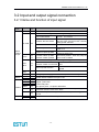
3.2 INPUT AND OUTPUT SIGNAL CONNECTION .....................................................................................16
3.2.1 Name and function of input signal.....................................................................................16
3.2.2Name and function of output signal....................................................................................17
3.2.3 Input and output connector(CN1)terminal array................................................................18
3.2.4 Encoder signal connection................................................................................................ 19
3.2.5 Communication signal connection.................................................................................... 19
3.2.6 Encoder cable & power cable connections....................................................................... 20
3.2.6.2 EMJ series servo motor..............................................................................................20
3.2.6.3 EMG series servo motor.............................................................................................20
3.2.6.4 EML series servo motor..............................................................................................21
3.2.6.5 EMB series servo motor............................................................................................. 22
3.3 STANDARD CONNECTION DIAGRAMS............................................................................................23
3.3.1 Three-phase 200V power supply specification................................................................. 23
3.3.2 Three-phase 400V power supply specification................................................................. 24
CHAPTER 4............................................................................................................................... 25
OPERATION INTRODUCTION................................................................................................. 25
4.1 OPERATION INTRODUCTION .........................................................................................................25
4.1.1 Digital Operator operation introduction............................................................................. 25
4.1.2 Basic Mode Selection........................................................................................................25
4.1.3 Operation in Status Display Mode.................................................................................... 26
4.1.4 Operation For position control...........................................................................................27
4.1.5 Operation for Parameter Setting Mode............................................................................. 28
4.1.6 Operation in Monitor Mode................................................................................................29
4.1.7 Operation in Assistant function mode............................................................................... 31
-3-
PRONET series User’s Manual V. 1.04
4.1.7.1 Operation in displaying alarm historical data............................................................. 32
4.1.7.2 Operation in recovering default value........................................................................ 32
4.1.7.2 Operation in JOG mode............................................................................................. 33
4.2 Simulative Reference Offset Automatic Adjustment.............................................................33
4.3 Analog Reference Offset Manual Adjustment.......................................................................35
4.4 Motor Current detection signal offset adjustment.................................................................37
4.5 Motor current detection offset manual adjustment............................................................... 38
4.6 Checking Servo Software Version........................................................................................38
4.7 Teaching position function.................................................................................................... 39
4.8 static inertia detection.......................................................................................................... 39
4.9 Clear absolute encoder multiple-circle information and error.............................................. 40
4.10 Clear absolute encoder relevant error............................................................................... 40
CHAPTER 5............................................................................................................................... 41
MODBUS COMMUNICATION................................................................................................... 41
5.1 MODBUS COMMUNICATION FUNCTIONS .....................................................................................41
5.1.1 RS-485 communication cable wiring.................................................................................41
5.1.2 MODBUS communication relevant parameters................................................................43
5.2 MODBUS COMMUNICATION ........................................................................................................44
5.2.1 ASCII mode:...................................................................................................................... 44
5.2.2 RTU mode:........................................................................................................................ 44
5.2.3 Communication protocol structure:................................................................................... 46
5.2.4 Communication error disposal.......................................................................................... 51
5.2.5 Servo state data communication address.........................................................................53
CHAPTER 6............................................................................................................................... 56
PARAMETER LIST.................................................................................................................... 56
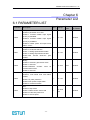
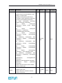
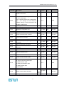
6.1 PARAMETER LIST.................................................................................................................. 56
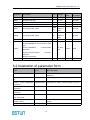
6.2 ILLUSTRATION OF PARAMETER FORM........................................................................................... 63
CHAPTER 7............................................................................................................................... 64
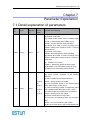
PARAMETER EXPLANATION................................................................................................. 64
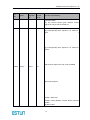
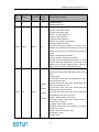
7.1 DETAIL EXPLANATION OF PARAMETERS........................................................................................ 64
APPENDIX................................................................................................................................. 84
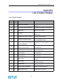
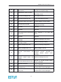
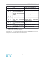
LIST OF ALARM DISPLAY........................................................................................................ 84
-4-
PRONET series User’s Manual V. 1.04
Chapter 1
Checking products and parts names
1.1 Check products
Check the following items after receiving Pronet Series AC servo systems:
Check Items
Whether the models are the same
as what were ordered.
Does the servomotor shaft rotate
smoothly?
Is there any damage?
Is there any screw loose?
Reference
Check the model numbers marked on the
nameplates on the servo motor and Servo drive.
(Refer to the descriptions of model numbers in
the following section.)
The servomotor shaft is normal if it can be turned
smoothly by hand. Servomotors with brakes,
however, cannot be turned manually.
Check the overall appearance, and check for
damage or scratches that may have occurred
during transportation.
Check with the screwdriver.
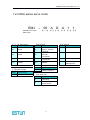
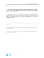
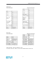
1.2 Model Designation
1.2.1 Pronet series servo drive
PRONET
–
【1+2】
rated power
Sign Specification
10
【1+2】
ESTUN Servo drive
PRONET Series
A
【3】
M
A
【4】
【5】
【3】power supply voltage
【5】design sequence
Sign
Specification
Sign
A
08
750W
A
200VAC
10
15
20
30
1.0kW
1.5kW
2.0kW
3.0kW
D
400VAC
50
5.0kW
75
7.5kW
1A
11kW
1E
15kW
【4】control mode
Sign
Specification
Speed ,torque &
M
position control
Speed,torque
&
position
control
E
(support extended
modue)
-5-
Specification
Design
sequence
PRONET series User’s Manual V. 1.04
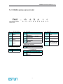
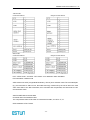
1.2.2 EMJ series servo motor
EMJ
–
ESTUN servo motor
EMJ series
【1+2】Rated power
Code
Specifications
02
200W
04
400W
08
750W
10
1000W
【3】Power voltage
Code
Specifications
A
200VAC
08
A D
A 1
【1+2】 【3】 【4】
【5】
1
【6】 【7】
【4】Encoder
Code
Specifications
Increamental wireP
saving encoder :
2500P/R
incremental
D
encoder
:
131072P/R
Absolute encoder
S
131072P/R
【7】Options
Code
Specifications
None
1
R
Resoler
4
【5】
Code
A
B
Design Sequence
Specifications
Design sequence
【6】Shaft end
Code
Specifications
Flat,without
keys
1
(standard)
Flat, with keys,with
2
screw thread
-6-
With oil seal
2
3
With brake(DC24V)
With oil seal,With
brake(DC24V)
PRONET series User’s Manual V. 1.04
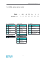
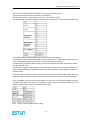
1.2.3 EMG series servo motor
EMG
ESTUN servo motor
EMG series
【1+2】rated power
Sign
Specification
10
1.0kW
15
1.5kW
20
2.0kW
30
3.0kW
50
5.0kW
–
10
【3】
D A
【4】
【5】
【4】encoder
Sign
Specification
Incremental
encoder
P
2500P/R
incremental
encoder
D
131072P/R
Absolute encoder
S
131072P/R
R
【3】power voltage
Sign Specification
A
200VAC
A
【1+2】
1
【6】
【7】options
Sign
Specification
:
:
2
1
None
2
With oil seal
3
With
(DC24V)
4
With oil seal,with
brake (DC24V)
Resoler
【5】Design sequence
Code Specifications
A
Design sequence
Sign
1
1
【7】
【6】shaft end
Specification
Flat,without keys(standard)
Flat,with keys,With screw
thread
-7-
brake
PRONET series User’s Manual V. 1.04
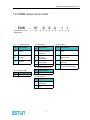
1.2.4 EML series servo motor
EML
ESTUN servo motor
EML series
【1+2】rated power
code
Specification
10
1.0kW
20
2.0kW
30
3.0kW
40
4.0kW
【3】power supply
code Specification
A
200VAC
–
10
【1+2】
A
【3】
D
【4】
A
【5】
【4】encoder
cod
Specification
e
Incremental
wireP
saving:2500P/R
incremental
D
Encoder
:
131072P/R
Absolute encoder
S
131072P/R
【7】option
R
Resolver
【5】Design Sequence
A
Design sequence
【6】shaft end
cod
Specification
e
Flat,without
keys
1
(standard)
Flat, with keys,with
2
screw thread
-8-
1
【6】
1
【7】
code
Specification
1
None
2
With oil seal
3
With brake (DC24V)
4
With oil seal
brake(DC24V)
and
PRONET series User’s Manual V. 1.04
1.2.5 EMB series servo motor
EMB
–
ESTUN servo motor
EMB series
【1+2】rated power
code
Specification
75
7.5kW
1A
11.0kW
1E
15.0kW
1E
【1+2】
D
【3】
S A
【4】
【4】encoder
co
Specification
de
Incremental wireP
saving encoder :
2500P/R
incremental
D
encoder
:
131072P/R
absolute encoder :
S
131072P/R
R
resolver
【5】design sequence
【3】power supply
code
D
Specification
400VAC
【5】
co
de
A
Specification
Design sequence
【6】shaft end
co
Specification
de
Flat, without keys
1
(standard)
Flat, with keys and
2
tap
-9-
1
【6】
1
【7】
【7】options
code
Specification
1
None
2
With oil seal
3
With
holding
(DC24V)
4
With oil seal and
holding brake(DC24V)
brake
PRONET series User’s Manual V. 1.04
Chapter 2
Installation
2.1 Servodrive
Pronet Series Servo drive is a base-mounted type servo controller. Incorrect installation will cause
problems. Always observe the installation instructions described below.
Caution
• Never use the products in an environment subject to water, corrosive gases,
inflammable gases, or combustibles.
Failure to observe this caution may result in electric shock or fire.
• Do not step on or place a heavy object on the product.
Failure to observe this caution may result in injury.
• Do not cover the inlet or outlet parts and prevent any foreign objects from
entering the product.
Failure to observe this caution may cause internal elements to deteriorate resulting
in malfunction or fire.
• Be sure to install the product in the correct direction.
Failure to observe this caution may result in malfunction.
• Provide the specified clearances between the SERVO DRIVE and the control
panel or with other devices.
Failure to observe this caution may result in fire or malfunction.
• Do not apply any strong impact.
Failure to observe this caution may result in malfunction.
2.2.1 Storage and transportation
When the Servo drive is to be stored with the power cable disconnected, store it in the following
temperature range: Between −20°C and 85°C
Caution
• Do not store or install the product in the following places.
• Locations subject to direct sunlight.
• Locations subject to temperatures outside the range specified in the storage or
installation temperature conditions.
• Locations subject to humidity outside the range specified in the storage or
installation humidity conditions.
• Locations subject to condensation as the result of extreme changes in
temperature.
• Locations subject to corrosive or flammable gases.
• Locations subject to dust, salts, or iron dust.
• Locations subject to exposure to water, oil, or chemicals.
• Locations subject to shock or vibration.
Failure to observe this caution may result in fire, electric shock, or damage to the
product.
• Do not hold the product by the cables or motor shaft while transporting it.
Failure to observe this caution may result in injury or malfunction.
• Do not place any load exceeding the limit specified on the packing box.
Failure to observe this caution may result in injury or malfunction.
-10-
PRONET series User’s Manual V. 1.04
2.2.2 Installation sites
Notes of operation installation are described as follows:
Condition
Safety notes
Installation in a Control Panel
Design the control panel size, unit layout, and
cooling method so the temperature around
the servo drive does not exceed 55 °C (131
°F)
Installation Near a Heating Unit
Minimize the heat radiating from the heating
unit as well as any temperature rise caused
by natural convection so the temperature
around the servo drive does not exceed 55
°C (131 °F).
Installation Near a Source of Vibration
Install a vibration isolator on the servo dirve
to avoid subjecting it to vibration.
Installation at a Site Exposed to Corrosive Corrosive gas does not have an immediate
Gas
effect on the servo drive but will eventually
cause the electronic components and
contactor-related devices to malfunction.
Take appropriate action to avoid corrosive
gas.
Other Situations
Do not install the servo drive in hot, humid
locations or locations subject to excessive
dust or iron powder in the air.
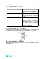
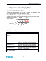
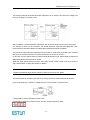
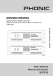
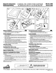
2.2.3 Installation orientation
Install the SERVO DRIVE perpendicular to the wall as shown in the figure. The Servo drive must be
oriented this way because it is designed to be cooled by natural convection or a cooling fan.
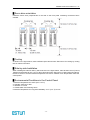
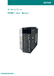
2.2.4 Installation method
When installing multiple Servodrives side by side in a control panel, observe the following
installation method:
-11-
PRONET series User’s Manual V. 1.04
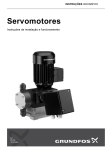
█ Servo drive orientation
Install the Servo drive perpendicular to the wall so the front panel containing connectors faces
outward.
█ Cooling
As shown in the figure above, allow sufficient space around each Servo drive for cooling by cooling
fans or natural convection.
█ Side-by-side Installation
When installing Servodrives side by side as shown in the figure above, allow at least 10 mm (0.39 in)
between and at least 50 mm (1.97 in) above and below each Servo drive. Install cooling fans above
the Servo drives to avoid excessive temperature rise and to maintain even temperature inside the
control panel.
█ Environmental Conditions in the Control Panel
1. Ambient Temperature:0 to 55°C (32 to 131° F)
2. Humidity: 90% RH or less
3. Vibration: 4.9 m/s2
4. Condensation and Freezing: None
5. Ambient Temperature for Long-term Reliability: 45 °C (113 °F) or less
-12-
PRONET series User’s Manual V. 1.04
█ Operation
Caution
• Conduct trial operation on the servomotor alone with the motor shaft
disconnected from machine to avoid any unexpected accidents.
Failure to observe this caution may result in injury.
• Before starting operation with a machine connected, change the settings to
match the parameters of the machine.
Starting operation without matching the proper settings may cause the machine to
run out of control or malfunction.
• Forward run prohibited (P-OT) and reverse run prohibited (N-OT) signals are not
effective in JOG mode.
• When using the servomotor for a vertical axis, install the safety devices to
prevent workpieces to fall off due to occurrence of alarm or overtravel. Set the
servomotor so that it will stop in the zero clamp state at occurrence of overtravel.
Failure to observe this caution may cause workpieces to fall off due to overtravel.
• Do not touch the SERVO DRIVE heatsinks, regenerative resistor, or servomotor
while power is ON or soon after the power is turned OFF.
Failure to observe this caution may result in burns due to high temperatures.
• Do not make any extreme adjustments or setting changes of parameters.
Failure to observe this caution may result in injury due to unstable operation.
• When an alarm occurs, remove the cause, reset the alarm after confirming safety,
and then resume operation.
Failure to observe this caution may result in injury.
• Do not use the servo brake of the servomotor for ordinary braking.
Failure to observe this caution may result in malfunction.
-13-
PRONET series User’s Manual V. 1.04
Chapter 3
Wirings and connections
3.1 Wirings and connections for main circuit
Always observe the following notes when wires or connects the circuit:
Caution
• Do not connect a three-phase power supply to the U, V, or W output terminals.
Failure to observe this caution may result in injury or fire.
• Securely connect the power supply terminals and motor output terminals.
Failure to observe this caution may result in fire.
• Do not bundle or run power and signal lines together in the same duct. Keep power and signal
lines separated by at least 30 cm (11.81 in).
Failure to observe this caution may result in malfunction.
• Use twisted-pair shielded wires or multi-core twisted pair shielded wires for signal and encoder
(PG) feedback lines.
The maximum length is 3 m (118.11 in) for reference input lines and is 20 m (787.40 in) for PG
feedback lines.
• Do not touch the power terminals for five minutes after turning power OFF because high voltage
may still remain in the SERVO DRIVE.
Make sure the charge indicator is turned OFF first before starting an inspection.
• Avoid frequently turning power ON and OFF. Do not turn power ON or OFF more than once per
minute.
Since the SERVO DRIVE has a capacitor in the power supply, a high charging current flows for
0.2 seconds when power is turned ON. Frequently turning power ON and OFF causes main
power devices such as capacitors and fuses to deteriorate, resulting in unexpected problems.
• Observe the following precautions when wiring main circuit terminal blocks.
• Remove the terminal block from the SERVO DRIVE prior to wiring.
• Insert only one wire per terminal on the terminal block.
• Make sure that the core wire is not electrically shorted to adjacent core wires.
• Do not connect the SERVO DRIVEfor 200 V directly to a voltage of 400 V.
The SERVO DRIVE will be destroyed.
• Always use the specified power supply voltage.
An incorrect voltage may result in burning.
• Take appropriate measures to ensure that the input power supply is supplied within the
specified voltage fluctuation range. Be particularly careful in places where the power supply is
unstable.
An incorrect power supply may result in damage to the product.
• Install external breakers or other safety devices against short-circuiting in external wiring.
Failure to observe this caution may result in fire.
-14-
PRONET series User’s Manual V. 1.04
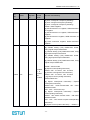
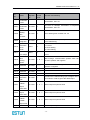
3.1.1 Names and Functions of Main Circuit Terminals
Power
supply
Drive
model
PRONET
-
200V
□□A
400V
□□D
-
-
200V
□□A
400V
□□D
Grounding terminal
-
-
Outside
resistor
terminal
200V
□□A
400V
□□D
200V
□□A
400V
□□D
-
-
Terminal
Symbol
Name
L1,L2,L3
Main circuit power
Supply input terminals
U,V,W
L1C,L2C
B1,B2,B3
Servo motor
connection terminals
Control circuit, power
supply input terminals
regenerative
connection
B1,B2
DC
reactor
for
harmonic suppression
terminal
Main
circuit
terminal
minus
-15-
Function
Three phase 200~230VAC+10,-15%
(50/60Hz)
Three phase 380~440VAC+10,-15%
(50/60Hz)
Connect with the servo motor
Single phase 200~230VAC+10,-15%
(50/60Hz)
Single phase 380~440VAC+10,-15%
(50/60Hz)
Connects to the power supply ground
terminal and servo motor ground terminal
Normal short B2-B3(for the inside
regenerative resistor). Remove the wire
between B2 and B3 and connect an
external regenerative resistor between B1
and B2 if the capacity of inside
regenerative resistor is insufficient
Connect an external regenerative resistor
between B1 and B2.
Normally,short
.If
countermeasure against power supply
harmonic waves is needed, connect an
DC reactor between
-
Normal not connected
PRONET series User’s Manual V. 1.04
3.2 Input and output signal connection
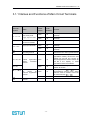
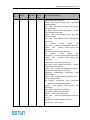
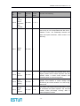
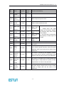
3.2.1 Name and function of input signal
Control
mode
Speed
Position
Torque
/S-ON
Pin
no.
14
/P-CON
15
P-OT
N-OT
16
17
Signal
Function
Servo ON:motor power on
Choose the following functions through setting parameter
If on , switch speed loop control mode
PI/P control switch
from PI to P control
Use this signal for switching rotation
Rotation direction switch
direction when use the function “internal
seting speed selection”
Control mode switch
Switch control mode
[Speed control]if ON, reference speed
Zero Clamp
value is “0”
[Position control] when ON, stop
Reference pulse prohibit
reference pulse input
Forward rotation prohibit
Reverse rotation prohibit
Over travel prohibit:when ON, stop the
servo motor’s rotation
Choose the following functions through setting parameter
/PCL
/NCL
Speed
Position
/ALMRST
DICOM
VREF+
VREFPULS+
PULSSIGN+
SIGNPPI
/CLR
Torque
T-REF+
T-REF-
41
42
Forward rotation current limit
Reverse rotation current limit
Current limit function is effective if
ON.
Internal speed selection
Choose
speed
different
internal
setting
39
Alarm reset:release servo alarm status
13
1
2
30
31
32
33
I/O signal power supply source,should provide 24VDC by the client
34
40
26
27
Speed reference difference input: ±10V
Pulse input form:
*signal+pulse train
*CCW+CW pulse
*two phase pulse(90°phase differential)
Collector open-circuit reference power source ( Separately preset
2KΩ/0.5W resistor inside of the drive)
Position error pulse clearing:clear position error pulse during position
control
Torque reference difference input:±10V
-16-
PRONET series User’s Manual V. 1.04
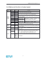
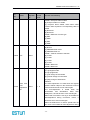
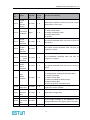
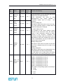
3.2.2Name and function of output signal
Control
mode
Speed
Position
Torque
Signal
Pin no.
ALM+
ALM/TGON+
/TGON/S-RDY+
/S-RDY-
5
6
7
8
9
PAO+
PAOPBO+
PBOPCO+
PCO-
20
21
22
23
24
25
Metal
shell
11
FG
Speed
/V-CMP+
/V-CMP-
Position
/COIN+
/COIN-
10
12
11
12
/CLT
/BK
—
—
4,18,19,
29,35,
36,37,
38,43,
44,45,
47, 49
Maintain
Function
Servo alarm:
Turn OFF when check abnormal status.
Motor rotation detect:
Turn on when motor rotation is over the setting value。
Servo ready:
Turn on if there is no alarm when control circuit and main
circuit are powered.
A phase signal
B phase signal
C phase signal
Two-phase ( A phase 、 B phase ) PG
frequency dividing output signal
Homing pulse(C phase)signal
If the shield of connector cable CN1 is connected with the
metal shell, it is connected with shell ground
Consistent speed:
Turn on when the speed of motor is in the same condition with
reference speed.
Position complete:
When on after position complete(deviation pulse reach to the
setting value)
Maintain functions could be allocated to /TGON、/S-RDY、/VCMP(/COIN)signal pins by amending parameter setting。
/CLT:Torque limit output. Above setting value ON
/BK:Breaker linkage output. Release break when on.
Unused pins
-17-
PRONET series User’s Manual V. 1.04
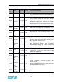
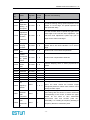
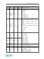
3.2.3 Input and output connector(CN1)terminal array
Pin
no.
1
2
3
4
5
6
7
8
Name
Function
VREF+
VREFAGND
—
ALM+
ALM/TGON+
/TGON-
Speed reference difference
input:±10V
Analog ground
Not use
9
/S-RDY+
10
11
12
/S-RDY/COIN+
/COIN-
13
DICOM
14
15
16
17
18
19
20
/S-ON
/P-CON
P-OT
N-OT
—
—
PAO+
21
PAO-
22
PBO+
23
PBO-
24
PCO+
25
PCO-
Servo alarm
Motor rotation detection
Servo ready
Position complete
I/O signal 24VDC power
supply
Servo ON
Position control switch
Forward drive prohibit
Reverse drive prohibit
Not use
Not use
Encoder A
Two
phase
phase
pulse
PG
signal
frequency
Encoder B
dividing output
phase
signal
signal
Encoder C
Homing pulse
phase
signal
signal
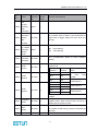
Pin
no.
26
27
28
29
30
31
32
33
Name
Function
T-REF+
T-REFAGND
—
PULS+
PULSSIGN+
SIGN-
Torque reference difference
input:±10V
Analog ground
Not use
Command pulse input
Command pulse input
34
PPI
35
36
37
—
—
—
Collector
open-circuit
reference power source
Not use
Not use
Not use
38
—
Not use
39
40
41
42
43
44
45
/ALM-RST
/CLR
/PCL
/NCL
—
—
—
Alarm release
Clear position bias pulse
Forward external torque limit
Reverse external torque limit
Not use
Not use
Not use
46
DGND
Digital ground
47
—
Not use
48
DGND
Digital ground
49
—
Not use
50
DGND
Digital ground
Note:
The following input and output can be allocated or change the function by user parameters setting.
Input: /S-ON, /P-CON, P-OT, N-OT, /ALM-RST, /CLR, /PCL, /NCL
Output: /TGON, /S-RDY, /COIN
Related details, please reference to ‘parameter detail explanation’ Pn509, Pn510 and Pn511
-18-
PRONET series User’s Manual V. 1.04
3.2.4 Encoder signal connection
● Encoder connector(CN2) terminal array
Pin
no.
1
2
3
4
5
6
7
8
9
10
Name
PA
/PA
PB
/PB
PC
/PC
PS
/PS
PG5V
Function
PG input A phase
PG input/A phase
PG input B phase
PG input/B phase
PG input C phase
PG input/C phase
PG serial signal input
PG serial signal input
PG power source +
5V
Pin
no.
11
12
13
14
15
16
17
18
19
20
Name
Function
PU
/PU
PV
/PV
PW
/PW
BAT+
BAT-
PG input U phase
PG input/U phase
PG input V phase
PG input/V phase
PG input W phase
PG input/W phase
Battery(+)[absolute encoder]
Battery(-)[absolute encoder]
GND
PG power source 0V
3.2.5 Communication signal connection
● Communication connector(CN3) terminal array
Terminal
1
2
3
4
5
6
7
8
Name
5V
5V
485+
DGND
DGND
485CANH
CANL
Function
5VDC power supply
RS-485 communication terminal
Grounding
RS-485 communication terminal
CAN communication terminal
CAN communication terminal
● Communication connector(CN4) terminal array
Terminal
1
2
3
4
5
6
7
8
Name
—
—
485+
DGND
DGND
485CANH
CANL
Function
Not use
Not use
RS-485 communication terminal
grounding
RS-485 communication terminal
CAN communication terminal
CAN communication terminal
-19-
PRONET series User’s Manual V. 1.04
3.2.6 Encoder cable & power cable connections
3.2.6.2 EMJ series servo motor
● Motor connector specification
connector:172167-1 (AMP)
pin: 170360-1 (AMP)
Pin
Signal
Color
No.
U
1
red
phase
V
2
blue
phase
W
3
white
phase
4
FG
Greenyellow
● Encoder connector specification
connector(pin):CGRSD-7BFMA-SL8001(CHOGRI)
Incremental/Absolute encoder
resolver
Pin
Pin
Signal Color
Signal
No.
No.
1
S+
blue
1
Sin+
2
SBlue/black
2
Sin★3
BAT+
brown
3
Cos+
★4
BATBrown/black
4
Cos5
PG5V Red
5
R1
6
PG0V black
6
R2
7
FG
shield
7
FG
Color
blue
yellow
red
black
Red/white
Yellow/white
shield
Notes:Incremental encoder has no BAT+、BAT- signal.
3.2.6.3 EMG series servo motor
● Motor receptacle specification
receptacle:MS3102A20-4P (EMG-10A/15A/20A);MS3102A22-22P (EMG-30A/50A)
connector:MS3108B20-4S (EMG-10A/15A/20A);MS3108B22-22S (EMG-30A/50A)
cable clamp:MS3057-12A
Pin
A
B
C
D
Signal
U phase
V phase
W
phase
FG
-20-
Color
red
blue
white
Green/yell
ow
PRONET series User’s Manual V. 1.04
●Encoder receptacle specification
receptacle:MS3102A20-29P
connector:MS3108B20-29S
cable clamp:MS3057-12A
Increamental/absolute encoder
pin
signal
colour
K
S+
Blue
L
SBlue/black
★T
BAT+
Brown
★S
BATBrown/black
H
PG5V
red
G
PG0V
black
J
FG
shield
pin
K
L
T
S
H
G
J
signal
Sin+
SinCos+
CosR1
R2
FG
resolver
color
blue
yellow
red
black
Red/white
Yellow/white
shield
Notes:Incremental encoder has no BAT+、BAT- signal.
3.2.6.4 EML series servo motor
● Motor receptacle specification
receptacle:MS3102A20-4P (EML-10A);MS3102A22-22P (EML-20A/30A/40A)
connector:MS3108B20-4S (EML-10A);MS3108B22-22S (EML-20A/30A/40A)
cable clamp:MS3057-12A
code
A
B
C
D
signal
U
phase
V
pahse
W
phase
FG
color
red
blue
white
Green/black
● Encoder receptacle specification
receptacle:MS3102A20-29P
connector:MS3108B20-29S
cable clamp:MS3057-12A
Increamental absolute encoder
pin
K
L
★T
★S
H
G
J
signal
S+
SBAT+
BATPG5V
PG0V
FG
colour
Blue
Blue/black
Brown
Brown/black
red
black
shield
-21-
resolver
pin
K
L
★T
★S
H
G
J
signal
Sin+
SinCOS+
COSR1
R2
FG
colour
Blue
Yellwo
red
black
Red/white
Yellow/white
shield
PRONET series User’s Manual V. 1.04
3.2.6.5 EMB series servo motor
● Motor receptacle specification
receptical:MS3102A32-17P
connector:MS3108B32-17S
cable clamp:MS3057-12A
code
A
B
C
D
signal
U
phase
V
phase
W
phase
FG
color
red
blue
white
Green/yellow
● Encoder receptacle specification
Receptacle:MS3102A20-29P
Connector:MS3108B20-29S
Cable clamp:MS3057-12A
absolute encoder
pin
K
L
T
S
H
G
J
signal
S+
SBAT+
BATPG5V
PG0V
FG
colour
Blue
Blue/black
Brown
Brown/black
red
black
shield
-22-
resolver
pin
K
L
T
S
H
G
J
signal
Sin+
SinCOS+
COSR1
R2
FG
colour
Blue
Yellwo
red
black
Red/white
Yellow/white
shield
PRONET series User’s Manual V. 1.04
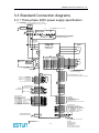
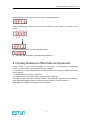
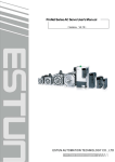
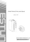
3.3 Standard Connection diagrams
3.3.1 Three-phase 200V power supply specification
非熔丝断路器 L1
Molded-case circuit breaker
1QF
L2
三相交流 200~230V +10%
-15% (50/60Hz)
Three-phase 200 to 230VAC +10%
-15% (50/60Hz)
L3
浪涌保护器
Surge protector
1Ry
噪声滤波器
Noise filter
电源OFF 电源ON
Power OFF Power ON
1KM
电磁接触器
Magnetic contector
1KM
1PL (伺服报警显示用 Servo alarm display)
1KM
1Ry
1SUP
请在电磁接触器的线圈上接上浪涌抑制器。
Be sure to attach a surge suppressor to the excitation
coil of the magnetic contactor and relay.
PRONET 系列
伺服驱动器
PRONET series
servo drives
L1
L2
L3
A(1)
U
B(2)
V
1
伺服电机
Servo motor
M
C(3)
W
D(4)
2
CN2
选项
增量式编码器
Options
Incremental encoder
1
A+
旋转变压器
绝对值编码器
Resolver
Absolute encoder
2
A3
7
SIN+
7
S+
B+
8
SIN8
S4
BCOS+
BAT+
5
C+
17
17
18
COS18
BAT6
C9
R1
9
PG5V
9
PG5V
19
19
19
R2
PG0V
PG0V
壳体 Shield
壳体 Shield
壳体 Shield
Shell
Shell
Shell
L1C
L2C
外置再生电阻器
External regenerative
resistor
B1
B1
B2
B2
B3
B3
必须接地。
Be sure to ground.
PG
CN3
1
2
3
4
5
6
7
8
壳体
Shell
CN1
10K
PPI
34
PULS+
PULS-
30
31
150Ω
SIGN+
SIGN-
32
33
150Ω
DICOM
S-ON
P-CON
P-OT
N-OT
ALM-RST
CLR
P-CL
N-CL
13
14
15
16
17
39
40
41
42
P
1
2
3
26
27
28
P
P
转矩指令 (±1V~10V / 额定转矩)
Torque reference
(±1V to 10V / rated motor torque)
集电极开路指令使用
Open-collector reference use
PULS / CW / A
SIGN / CCW / B
+24V
可进行信号的分配 :
Signal allocations can be modified:
S-ON: 伺服使能 Servo ON
P-CON: 比例控制 P control
P-OT: 正转驱动禁止 Forward run prohibited
N-OT: 反转驱动禁止 Reverse run prohibited
ALM-RST: 报警复位 Alarm reset
CLR: 位置偏差清零 Clear error pulse
P-CL: 正转转矩限制 Forward torque limit
N-CL: 反转转矩限制 Reverse torque limit
40K
VREF+
VREFAGND
TREF+
TREFAGND
P
速度指令 (±1V~10V / 额定转速)
Speed reference
(±1V to 10V / rated motor speed)
位置指令
Position reference
编码器
Encoder
ref
+
40K
10K
A/D
ref
+
-
+5V
+5V
485+
DGND
DGND
485CANH
CANL
请切实进行屏蔽线的末端处理。
Be sure to prepare the end of
the shielded wire properly.
通过专用通讯电缆连接 PC(个人电脑)
Use special communication cable link PC(personal computer)
Shield
CN4
2KΩ
2KΩ
3.3KΩ
1
2
3
4
5
6
7
8
壳体
Shell
N.C.
N.C.
485+
DGND
DGND
485CANH
CANL
20
21
22
23
24
25
50
PAO+
PAOPBO+
PBOPCO+
PCODGND
PG分频输出
适用线接收器
TI公司 AM26LS32A 或同类产品
PG dividing ratio output
Applicable line receiver
AM26LS32A manufactured by TI or the equivalent
7
8
9
10
11
12
TGON+
TGONS-RDY+
S-RDYV-CMP+
V-CMP-
可进行信号的分配:
Signal allocations can be modified:
V-CMP: 速度一致 Speed agree detection
COIN: 定位完成 Positioning completion
TGON: 电机旋转检测 Motor rotation detection
S-RDY: 伺服准备就绪 Servo ready
CLT: 转矩限制检测 Torque limit detection
BK: 制动器连锁 Brake interlock
5
6
ALM+
ALM-
Shield
1Ry
屏蔽线与连接器壳体相连。
Connect shield to connector shell.
Shield
壳体
Shell
+24 V
1D
0V
P
ALM: 伺服报警输出 Servo alarm output
表示双股绞合线
Represents twisted-pair wires
-23-
光耦输出:
最大工作电压 DC30V
最大输出电流 DC50mA
Photocoupler output:
Maximum operating voltage: 30VDC
Maximum operating current: 50mA DC
PRONET series User’s Manual V. 1.04
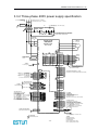
3.3.2 Three-phase 400V power supply specification
三相交流 380 ~440V +10%
-15% (50/60Hz)
Three-phase 380 to 440VAC +10%
-15% (50/60Hz)
L3
非熔丝断路器
Molded-case circuit breaker
1QF
浪涌保护器
Surge protector
1Ry
噪声滤波器
Noise filter
1PL (伺服报警显示用 Servo alarm display)
电源OFF 电源ON
Power OFF Power ON
1KM
电磁接触器
Magnetic contector
1KM
1KM
1Ry
1SUP
请在电磁接触器的线圈上接上浪涌抑制器。
Be sure to attach a surge suppressor to the excitation
coil of the magnetic contactor and relay.
PRONET 系列
伺服驱动器
PRONET series
servo drives
L1
L2
L3
A(1)
U
B(2)
V
伺服电机
Servo motor
M
C(3)
W
D(4)
CN2
选项
Options
L1C
旋转变压器
Resolver
7
SIN+
8
SIN17
COS+
18
COS9
R1
19
R2
壳体 Shield
Shell
L2C
外置再生电阻器
B1
External regenerative
resistor
B2
必须接地。
Be sure to ground.
绝对值编码器
Absolute encoder
7
S+
8
S17
BAT+
18
BAT9
PG5V
19
PG0V
壳体 Shield
Shell
编码器
Encoder
PG
CN3
1
2
3
4
5
6
7
8
壳体
Shell
CN1
10K
PPI
34
PULS+
PULS-
30
31
150Ω
SIGN+
SIGN-
32
33
150Ω
DICOM
S-ON
P-CON
P-OT
N-OT
ALM-RST
CLR
P-CL
N-CL
13
14
15
16
17
39
40
41
42
P
1
2
3
26
27
28
P
P
转矩指令 (±1V~10V / 额定转矩)
Torque reference
(±1V to 10V / rated motor torque)
集电极开路指令使用
Open-collector reference use
PULS / CW / A
40K
VREF+
VREFAGND
TREF+
TREFAGND
P
速度指令 (±1V~10V / 额定转速)
Speed reference
(±1V to 10V / rated motor speed)
位置指令
Position reference
增量式编码器
Incremental encoder
1
A+
2
A3
B+
4
B5
C+
6
C9
PG5V
19
PG0V
壳体 Shield
Shell
ref
+
40K
10K
A/D
ref
+
-
+24V
可进行信号的分配 :
Signal allocations can be modified:
S-ON: 伺服使能 Servo ON
P-CON: 比例控制 P control
P-OT: 正转驱动禁止 Forward run prohibited
N-OT: 反转驱动禁止 Reverse run prohibited
ALM-RST: 报警复位 Alarm reset
CLR: 位置偏差清零 Clear error pulse
P-CL: 正转转矩限制 Forward torque limit
N-CL: 反转转矩限制 Reverse torque limit
请切实进行屏蔽线的末端处理。
Be sure to prepare the end of
the shielded wire properly.
通过专用通讯电缆连接 PC(个人电脑)
Use special communication cable link PC(personal computer)
Shield
CN4
2KΩ
2KΩ
SIGN / CCW / B
+5V
+5V
485+
DGND
DGND
485CANH
CANL
3.3KΩ
1
2
3
4
5
6
7
8
壳体
Shell
N.C.
N.C.
485+
DGND
DGND
485CANH
CANL
20
21
22
23
24
25
50
PAO+
PAOPBO+
PBOPCO+
PCODGND
PG分频输出
适用线接收器
TI公司 AM26LS32A 或同类产品
PG dividing ratio output
Applicable line receiver
AM26LS32A manufactured by TI or the equivalent
7
8
9
10
11
12
TGON+
TGONS-RDY+
S-RDYV-CMP+
V-CMP-
可进行信号的分配:
Signal allocations can be modified:
V-CMP: 速度一致 Speed agree detection
COIN: 定位完成 Positioning completion
TGON: 电机旋转检测 Motor rotation detection
S-RDY: 伺服准备就绪 Servo ready
CLT: 转矩限制检测 Torque limit detection
BK: 制动器连锁 Brake interlock
5
6
ALM+
ALM-
Shield
1Ry
屏蔽线与连接器壳体相连。
Connect shield to connector shell.
Shield
壳体
Shell
+24 V
1D
0V
P
ALM: 伺服报警输出 Servo alarm output
表示双股绞合线
Represents twisted-pair wires
-24-
光耦输出:
最大工作电压DC30V
最大输出电流DC50mA
Photocoupler output:
Maximum operating voltage: 30VDC
Maximum operating current: 50mA DC
PRONET series User’s Manual V. 1.04
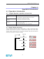
Chapter 4
Operation introduction
4.1 Operation introduction
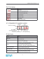
4.1.1 Digital Operator operation introduction
Name
Function
INC key
Press to display the parameter settings and set values.
Press INC key to increase the set value
Press DEC key to decrease the set value.
DEC key
MODE key
Press to select the status display mode, set mode, monitor mode,
or error trace back mode.
Press to cancel setting when set the parameters.
ENTER key
Press to display the parameter set, set values and release alarm.
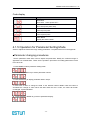
4.1.2 Basic Mode Selection
Through swithching among basic modes of digital operator, It is able to operate status display,
parameter setting, Monitor and operation etc. Digital Operator operation allows status display,
parameter setting, operating reference, and auto-tuning operations. Each time the mode key is
pressed, the next mode in the sequence is selected.
Power ON
Status display mode
Parameter setting mode
Monitor mode
Assistant mode
-25-
PRONET series User’s Manual V. 1.04
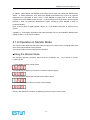
4.1.3 Operation in Status Display Mode
The status display mode displays the Servo drive status as bit data and codes.
■Selecting Status Display Mode
The status display mode is displayed when the power is turned ON. If the status display mode
does not displayed, select the mode by using Mode Key to switch.
■Keys for the status display are shown below
The display varies in different contents among speed control, torque control and position control.
For Speed and torque Control
Bit data
Code
Speed coincidence *
Base block
Control Power ON
Speed Reference Inputing
/TGON
Power ready
Torque Reference Input
* It is highlighted when in torque control mode.
Bit displays contents
Bit data
Descriptions
Control Power ON
Lit when SERVODRIVE control power ON.
Base block
Lit at base block.
Not lit at servo ON.
Speed Coincidence
Lit when the error between motor speed and the
reference speed is below preset value
Preset value:Pn501(standard value10min/r)
/TGON
Lit when motor speed exceeds preset value.
Not lit if motor speed is below preset value
Preset value: set in Pn503(standard value 20r/min)
Speed Reference Input
Lit if input speed reference exceeds preset value.
Not lit if input speed reference is below preset value.
Preset value: set in Pn503(standard value 20r/min)
Torque Reference Input
Lit if input torque reference exceeds preset value.
Not lit if input torque reference is below preset value.
Preset value:10% rated torque
Main circuit Power Ready
Lit when main power supply circuit is normal.
Not lit when power is OFF
-26-
PRONET series User’s Manual V. 1.04
Brief-Code displays
Code
Description
Base block
Servo OFF (motor power OFF)
Run
Servo ON (motor power ON)
Forward Rotation Prohibited (P-OT)
P-OT OFFstatus
Reverse Rotation Prohibited (N-OT)
N-OT OFF status
Alarm Status
Displays alarm number
Press ENTER to clear present alarm.
4.1.4 Operation For position control
Bit Data
Code
Positioning Complete
Base block
Control power ON
Reference Pulse Inputing
/TGON
Power Ready
Clear signal Inputing
Bit data dispaly
Bit data
Display
Control power ON
Lit when Servo drive control power ON.
Base block
Lit at base block.
Not lit at servo ON.
Position
Lit if error between position reference and actual motor
position is below preset value.
Preset value:Pn501(standard setting:10 pulse)
/TGON
Lit if motor speed exceeds preset value.
Not lit if motor speed is below preset value.
Preset value:set in Pn50(standard setting:20r/min)
Reference pulse input
Lit if reference pulse is input
Not lit if no reference pulse is input.
Clear signal Input
Lit when error counter clear signal is input.
Not lit when error counter clear signal is not input.
Main circuit Power Ready
Lit when main circuit power is normal.
Not lit when main circuit power is OFF
-27-
PRONET series User’s Manual V. 1.04
Code display
Code
Description
Base Block
Servo OFF.(motor power OFF)
Run
Servo ON (motor power ON)
Forward Rotation Prohibited
1CN-12 (P-OT) OFF.
Reverse Rotation Prohibited
1CN-13 (N-OT) OFF
Alarm Status
Display the alarm number
Press ENTER to clear alarm if present status is alarm
4.1.5 Operation for Parameter Setting Mode
Select or adjust the functions through setting parameters. The parameter list is in the appendix.
■Parameter changing procedures
Set the parameter datas when need to adjust the parameters. Modify the confirmed range in
Appendix List of Parameters. These are the operation procedures for setting parameters Pn102
from 100 to 85.
1. Press MODE to select parameter setting mode.
2. Press INC key or DEC key to select parameter number.
3. Press ENTER key to display parameter data in step 2.
4. Press INC or DEC to change the data to the desired number 00085. Hold the button to
accelerate the change of value. When the data reach the max. or Min., the value will remain
unchanged, if press INC/DEC.
5. Press ENTER or MODE to go back to parameter display.
-28-
PRONET series User’s Manual V. 1.04
In addition, press MODE and ENTER at the same time to enter into parameter displacement
status to modify parameter, then press both MODE and ENTER key to back off. Operate
displacement of parameter in step 3 and 4. Press ENTER for longer time to enter into edit
condition then press MODE to save and quit,or perss ENTER for a longer time to quit then press
ENTER to back off parameter displacement edition status,then press ENTER to back to
parameter display.
Note: If the left side of digital operator display “b”, it will display parameter in present binary
system.
If display “H”, it will display Hexadecimal and this parameter can only be modified in displacement
editing condition, or can not be modified.
4.1.6 Operation in Monitor Mode
The monitor mode allows the reference values to input into the Servo Drive, I/O signal status, and
Servo drive internal status to be monitored.
The monitor mode can be set during motor operation.
■Using the Monitor Mode
The example operation procedure below show how to display 150,
number Un-001.
the contents of monitor
1. Press MODE to select monitor mode.
2. Press INC key or DEC key to select the monitor number to display.
3. Press ENTER to display the selected monitor data at step 2.
4. Press ENTER again to back to monitor number display.
Above is the opertation procedure for displaying 1500 in monitor number Un001
-29-
PRONET series User’s Manual V. 1.04
■Monitor Mode Displays
Below is the monitor mode dispalys:
Monitor No.
contents
Un000
Actual motor speed r/min
Un001
Input speed reference value r/min
Un002
Input torque reference percentage% (with
relative rated torque)
Un003
Internal torque reference
reletive rated torque)
Un004
Encoder rotating angle pulse numbers
Un005
Input signal monitor
Un006
Encoder signal monitor
Un007
output signal monitor
Un008
Pulse given frequency (Unit: 1KHz)
Un009
Pulse count of motor rotated
Un010
Pulse rate of motor rotated
(x104)
Un011
Error pulse counter lower 16 digit
Un012
Error pulse counter higher 16 digit
Un013
Received pulse counter lower digit
Un014
Received pulse counter high digit (x104)
Un015
Load inertia percentage
Un016
Motor overload ratio
value%(with
Bit data display
Monitor No.
Un005
Bit No.
Display
0
1CN_14 input
1
1CN_15 input
2
1CN_16 input
3
1CN_17 input
4
1CN_39 input
5
1CN_40 input
6
1CN_41 input
7
1CN_42 input
-30-
internal status bit display
PRONET series User’s Manual V. 1.04
Monitor No.
Un006
Monitor No.
Un007
Bit No.
Dispaly
0
W phase
1
V phase
2
U phase
3
C phase
4
B phase
5
A phase
6
(Not used)
7
(Not used)
Bit No.
Content
0
1CN_05,1CN_06
1
1CN_07,1CN_08
2
1CN_09,1CN_10
3
1CN_11,1CN_12
4.1.7 Operation in Assistant function mode
Use panel malipulator to do some application operation when in assistant function mode,The
detailed functions are shown as below:
Function No.
Content
Fn000
Display historical alarm data
Fn001
recover factury default
Fn002
JOG mode
Fn003
speed
reference
autoregulation
Fn004
speed reference hand regulation
Fn005
Motor current
autoregulation
Fn006
Motor current inspection offset hand
regulation
Fn007
Servo software version display
Fn008
Positon Teaching function
Fn009
Static inertia inspection
Fn010
Clear
absolute
value
information and error
Fn011
Clear absolute
relavent error
offset
inspection
value
offset
loopy
encoder
-31-
PRONET series User’s Manual V. 1.04
4.1.7.1 Operation in displaying alarm historical data
The latest ten times alarms could be displayed in alarm historical data
The following shows the procedure to display the historical data.
1.Press MODE to select assistant function mode
2.Press INC or DEC to select function number of alarm historical record.
3.Press ENTER to display the latest alarm code.
Alarm serial number Alarm code
4.Press INC or DEC to display other recent occurred alarm code.
5.Press ENTER to return to function number display.
If the user wants to clear all the historical record, just hold ENTER for one second with displaying
alarm code , then all the historical data will be deleted.
4.1.7.2 Operation in recovering default value
The follows are procedures for recovering default value.
1.Press MODE to select assistant mode.
2.Press INC or DEC to select function number of recovering parameter default value
3.Press ENTER to enter parameter default recovery mode.
4. Hold ENTER key for one second to recover parameter to default value.
-32-
PRONET series User’s Manual V. 1.04
5. Release ENTER key to return to function number display.
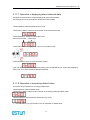
4.1.7.2 Operation in JOG mode
The following are the operation procedures in JOG mode
1.Press MODE to select assistant function mode.
2.Press INC or DEC to select Function number of JOG mode.
3.Press ENTER to enter JOG mode.
4.Press MODE to enter Servo ON (motor ON) status.
5.Press MODE to switch between servo ON and Servo OFF. If motor running is required, servo
must be ON.
Motor runs when press INC or DEC.
6. Press ENTER to return to function number display.Servo is OFF. (Motor is not under positon.)
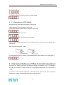
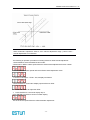
4.2 Simulative Reference Offset Automatic Adjustment
The motor may rotate slowly when the reference voltage is intended to be 0 V. This happens
when the host controller or external circuit has a small offset (measured in mV) in the reference
voltage.
The reference offset automatic adjustment mode automatically measures the offset and adjusts
the reference voltage. It adjusts both speed and torque references.
-33-
PRONET series User’s Manual V. 1.04
The following diagram illustrates automatic adjustment of an offset in the reference voltage from
the host controller or external circuit.
After completion of offset automatic adjustment, the amount of offset is stored in the Servodrive.
The amount of offset can be checked in the speed reference offset manual adjustment mode.
Please Refer to Simulative Reference Offset Manual Adjustment Mode for details
The reference offset automatic adjustment mode cannot be used where a position loop is formed
with the host controller and the error pulses recorded in servo are set to zero.
In this case, use the speed reference offset manual adjustment mode. Please Refer to Reference
Offset Manual Adjustment Mode for details.
When the input speed reference is zero, Zero-clamp speed control is able to force the motor to
stop. Please Refer to Using Zero-Clamp for details.
Note
Please automatively adjust analog reference offset on the servo OFF status.
The following are the operation procedures for analog reference offset automatic adjustment.
Input the (intended) 0 V reference voltage from the host controller or external circuit.
1.Press Mode to select assistant function mode.
2.Press INC or DEC key to select function number of speed reference offset.
-34-
PRONET series User’s Manual V. 1.04
3.Press ENTER to enter speed reference offset automatic adjustment.
4.Press MODE.Speed offset will be automatically adjusted after displaying twinkling for one
minute.
5.Press ENTER to return to function number display
6. This is the end of reference offset automatic adjustment.
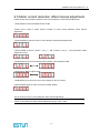
4.3 Analog Reference Offset Manual Adjustment
Analog reference offset manual adjustment is the function of speed/torque control(analog
reference) mode. Please use it under the following conditions:
• If position loop is formed with the host controller and adjust the offset pulse ZERO when servo
lock is stopped.
• To deliberately set the offset to some value.
It is available when checking the data of offset automatic adjustment.
The basic function is the same as analog reference offset automatic adjustment.But must directly
input offset while adjusting.Offset can be set as speed reference or torque reference.
Offset Adjustment Range and Setting Units are as follows:
-35-
PRONET series User’s Manual V. 1.04
Note:
When automatic adjustment offset is over manual adjustment range (-1024~+1024 ),
manual adjustment is not effective.
The following is operation procedures of analog reference offset manual adjustment.
1.Press MODE to select assistant function mode.
2.Press INC or DEC to select speed reference offset manual adjustment function number
3.Press ENTER to enter speed reference offset manual adjustment mode.
4. Set servo ON signal(/S-ON)ON, it displays as follows
5.Press ENTER for a second to display speed reference offset
6. Press INC or DEC to adjust the offset.
7. Press ENTER for a second to display step 4.
Press ENTER to go back to function number display.
This is the end of speed reference offset automatic adjustment.
-36-
PRONET series User’s Manual V. 1.04
4.4 Motor Current detection signal offset adjustment
Current detection offset is adjusted at Estun before shipping. Basically, the customer need not
perform this adjustment. Perform this adjustment only if highly accurate adjustment is required
when the Digital Operator is combined with a specific motor.
This section illustrates the offset automatic adjustment and manual adjustment operation
Note:
Motor current detection offset adjustment could only be performed when the Servo is OFF.
Deteriorated situations might occur when start this function involuntary; especially start the
manual adjustment involuntary.
Please perform the offset automatic adjustment when torque pulse is obviously too high
compared with other servodrivers.
Motor current detection offset automatic adjustment
Follow the procedure below to perform current detection offset automatic adjustment
1.Press MODE to select assistant function mode.
2.Press INC or DEC to select function number of motor current detection offset automatic
adjustment
3.Press ENTER to enter motor current detection offset automatic adjustment mode.
4. Press MODE and offset will be adjusted after flashing for a second.
5. Press ENTER to return function number display.
This is the end of motor current detection offset automatic adjustment
-37-
PRONET series User’s Manual V. 1.04
4.5 Motor current detection offset manual adjustment
Follow the procedure below to perform motor current detection offset manual adjustment
1.Press MODE to select assistant function mode.
2.Press INC or DEC to select function number of motor current detection offset manual
adjustment.
3.Press ENTER to enter into motor current detection offset manual adjustment.
4.Press MODE to switch U phase ( Cu1_o ) and V phase ( Cu2_o ) current detection offset
adjustment mode.
5.Hold ENTER for a second to diplay present phase current detection data.
6.Press INC or DEC to adjust offset.
7.Hold ENTER for a second to return to the display of step 3 or step 4.
8.Press ENTER again to return to function number display.
This is the end of motor current detection offset manual adjustment
Note:
Motor current detection offset manual adjustment range:-1024~+1024。
-38-
PRONET series User’s Manual V. 1.04
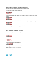
4.6 Checking Servo Software Version
The follow bellow is the operation procedures of servo software version.
1. Press MODE to select assistant function mode.
2.Press INC or DEC to select the function number of servo software version.
3.Press ENTER to display DSP software version number(D or E or F is displayed at the highest
position)
4.Press MODE to display FPGA/CPLD software version number(P is displayed at the highest
position)
5.Press MODE again to switch back to display the DSP software version number
6.Press ENTER to return to display the function number
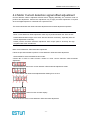
4.7 Teaching position function
Following operation procedure is for teaching position.
1. Press MODE to select assistant function mode.
2.Press INC or DEC to select the function number of servo software version.
3.Press ENTER to display as follows
4.Press ENTER for long to display as follows
5.Teaching has been completed and release ENTER
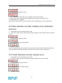
4.8 static inertia detection
1. Press MODE key, choose assistant function mode
2.Press INC or DEC, choose servo software edition display function number
-39-
PRONET series User’s Manual V. 1.04
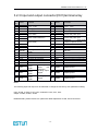
3.Press ENTER to display as follows:
4.Press MODE key to start rotate. Here, it displays motor dynamic speed.
5.When motor stops, it displays the total inertia of motor and load. The unit is kg.cm²
The inertia detection is complete.
Note: Please assure that motor has more than 6 circles of displacement in the CCW direction.
4.9 Clear absolute encoder multiple-circle information
and error
1. Press MODE, choose assistant function mode
2. Press INC or DEC, choose clear absolute encoder multiple-circle information and error function
number.
3.Press ENTER to display as follows:
4.Press MODE to proceed clear operation.
5.Operation complete
Note: This operation will clear the absolute position of the encoder. Please assure mechanical and
personnel safety beforehand. Besides, it will clear other encoder errorat the same time.
4.10 Clear absolute encoder relevant error
1. Press MODE, choose assistant function mode
2. Press INC or DEC, choose clear absolute encoder relevant error function number
3. Press ENTER to display as follows:
4.Press MODE to proceed clear operation
5. Operation complete
-40-
PRONET series User’s Manual V. 1.04
Chapter 5
Modbus communication
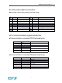
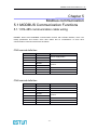
5.1 MODBUS Communication Functions
5.1.1 RS-485 communication cable wiring
PRONET drivers have MODBUS communication function with RS-485 interface, which can
modify parameters and monitor servo drive status and so on.Definitions of servo drive
communication connector terminal are as follows:
CN3 terminal definition:
Interface No.
Name
Function
1
5V
2
5V
3
485+
4
DGND
5
DGND
6
485-
RS-485 communication terminal
7
CANH
CAN communication terminal
8
CANL
CAN communication terminal
Power supply:5VDC
RS-485 communication terminal
ground
CN4 terminal definition:
Interface No.
Name
Function
1
—
maintain
2
—
maintain
3
485+
RS-485 communication terminal
4
DGND
5
DGND
6
485-
RS-485 communication terminal
7
CANH
CAN communication terminal
8
CANL
CAN communication terminal
ground
-41-
PRONET series User’s Manual V. 1.04
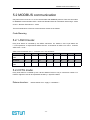
Instructions:
(1)The cable length can reach 100 meters when in a less disturbed environment.,However, if
transmission speed is above 9600bps, please use less than 15 meters communication cable to
ensure the accuracy of transmission.
(2)It’s available for up to 31 PCS servo drives to work together when RS485 is applied. 485
network end-point need to connect a 120Ω resistor separately.If need to connect more
appliances.If you want to connect with more appliance,a RS485 repeater must be needed to
expand connection units.
( 3 ) CN3 of servo drive is always taken as input terminals , and CN4 is always taken as
communication cable output terminals(If still need to connect slave station,connect cable from
this terminal to the next slave station facility; if needn’t, add balance resistor in this terminal ).If
sevral pronet servo drives connected, it is prohibited to directly connect CN3 of any two servo
drivers.
For example,RS-485 network is composed of a piece of PLC,A,B,C three sets of Pronets. Cable
wirring is as follows:
PLC→CN3 of drive A , CN4 of drive A→CN3 of drive B, CN4 of drive B→CN3 of drive C, CN4 of
drive C→120Ω terminal resistor.
-42-
PRONET series User’s Manual V. 1.04
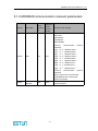
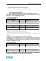
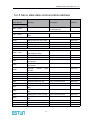
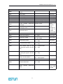
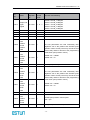
5.1.2 MODBUS communication relevant parameters
Pa. No.
discription
need
repower
on
Effective
under
control
mode
Function and meaning
Pn700
Hex
Yes
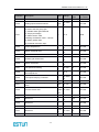
ALL
Pn700.0 MODBUS communication
baud rate
[0] 4800bps
[1] 9600bps
[2] 19200bps
Pn700.1
communication
protocol
selection
[0] 7,N,2(Modbus,ASCII)
[1] 7,E,1(Modbus,ASCII)
[2] 7,O,1(Modbus,ASCII)
[3] 8,N,2(Modbus,ASCII)
[4] 8,E,1(Modbus,ASCII)
[5] 8,O,1(Modbus,ASCII)
[6] 8,N,2(Modbus,RTU)
[7] 8,E,1(Modbus,RTU)
[8] 8,O,1(Modbus,RTU)
Pn700.2
communication
protocol
selection
[0] no protocol SCI communicate
[1] MODBUS SCI communicate
Pn700.3 maintain
Pn701
Modbus Axis
address
Yes
ALL
Aix address of MODBUS protocol
communication
-43-
PRONET series User’s Manual V. 1.04
5.2 MODBUS communication
Only when Pn213 is set as 1 or 2 can communicate with MODBUS protocol.There are two modes
for MODBUS communication:ASCII(American Standard Code for information interchange)mode
or RTU(Remote Terminal Unit)mode.
The brief introductions of the two communication modes are as follows:
Code Meaning
5.2.1 ASCII mode:
Every 8-bit datum is consisted by two ASCII characters. For instance: One 1-byte datum 64
H(Hex expression)is expressed as ASCII code ‘64’. It contains‘6’ as ASCII code(36 H) and‘4’as
ASCII code(34 H).
ASCII code for Number 0 to 9、character A to F are as follows:
Number
‘0’
‘1’
‘2’
‘3’
‘4’
‘5’
‘6’
‘7’
Relevant ASCII
code
30H
31H
32H
33H
34H
35H
36H
37H
Character
‘8’
‘9’
‘A’
‘B’
‘C’
‘D’
‘E’
‘F’
Relevant ASCII
code
38H
39H
41H
42H
43H
44H
45H
46H
5.2.2 RTU mode:
Every 8-bit datum is consisted by two 4-bit hex datums.That is to say, a normal hex number. For
instance: algorism 100 can be expressed as 64H by 1-byte RTU datum
Datum structure:
10bit character form(apply in 7-bit datum)
P n 0 6 2 =0:7,N,2(M odbus,A SCII )
Sta rt
b it
0
1
2
3
4
5
7-da ta bits
1 0 - bits character frame
-44-
6
Stop
b it
Stop
b it
PRONET series User’s Manual V. 1.04
P n 0 6 2 =1:7,E,1(M odbus,A SCII )
Sta rt
b it
0
1
2
3
4
5
6
Even
pa rity
Stop
b it
6
O dd
pa rity
Stop
b it
7-da ta bits
1 0 - bits character frame
P n 0 6 2 =2:7,O,1(M odbus,A SCII )
Sta rt
b it
0
1
2
3
4
5
7-da ta bits
1 0 - bits character frame
11bit character form(apply in 8-bit datum)
8,N,2(Modbus,ASCII / R T U )
Sta rt
b it
0
1
2
3
4
5
6
7
Stop
b it
Stop
b it
6
7
Even
pa r ity
Stop
b it
6
7
O dd
pa r ity
Stop
b it
8-da ta bits
1 1 - bits character frame
8,E,1(Modbus,ASCII / R T U )
Sta rt
b it
0
1
2
3
4
5
8-da ta bits
1 1 - bits character frame
8,O,1(Modbus,ASCII / R T U )
Sta rt
b it
0
1
2
3
4
5
8-da ta bits
1 1 - bits character frame
-45-
PRONET series User’s Manual V. 1.04
5.2.3 Communication protocol structure:
Communication protocol data format:
ASCII mode:
STX
Start charactor‘:’=>(3AH)
ADR
Communication address=>1-byte contains 2 pcs of ASCII code
CMD
Reference code=>1-byte contains 2 pcs of ASCII code
DATA(n-1)
Data content=>n-word=2n-byte contains 4 pcs of ASCIIcode,n≤12
……
DATA(0)
LRC
Checking code=>1-byte contains 2 pcs of ASCII code
End 1
End code 1=>(0DH)( CR)
End 0
End code 0=>(0AH)( LF)
RTU mode:
STX
At least stop transimission for 10ms
ADR
Communication address=>1-byte
CMD
Reference code=>1-byte
DATA(n-1)
Data content=>n-word=2n-byte,n≤12
……
DATA(0)
CRC
CRC Verifying code =>1-byte
End 1
At least stop transimission for 10ms
Communication protocol data format instructions are as follows:
STX(communication start)
ASCII mode:‘ : ’character
RTU mode: stop time for more than 4 bytes communication tim e(automatively changed according
to different communication speed)
ADR(communication address)
Valid communication addresses range from 1 to 254.
For example:communicate with the servo drive which address is 32(hex as 20):
ASCII mode:ADR=‘2’,‘0’=>‘2’=32H,‘0’=30H
RTU mode:ADR=20H
CMD(order instruction) and DATA(datum)
Datum structure is formed by order code. Regular order code as follows:
Order code: 03H, read N words(word),N is not morethan 20.
For instance: read 2 words from address 0200 H which start from servo addressed at 01 H
-46-
PRONET series User’s Manual V. 1.04
ASCII mode:
Order information:
response information:
RTU mode:
Order information:
Response information:
Order code: 06H,write in one character(word)
For instance: write 100(0064 H)into 01H servo address 0200 H of servo 01H.
-47-
PRONET series User’s Manual V. 1.04
ASCII mode:
Order information:
Response information:
RTU mode:
Order information:
Response information:
LRC(ASCII mode)and CRC(RTU mode)error detection value calculation:
LRC calculation in ASCII mode
ASCII mode uses LRC (Longirudinal Redunancy Check) error detection value.The exceeded part
(e.g. the total value is 128H of hex, then take 28H only) is taken off by the unit of 256 in the total
value from ADR to the last information, then calculate and compensate, the final result is LRC
error detection value.
Add from ADR data to the last data.
01H+03H+02H+01H+00H01H=08H
The compensate value is F8H when 2 is selected from 08H, so LRC is “F”,”8”.
CRC calculation of RUT mode:
-48-
PRONET series User’s Manual V. 1.04
RTU mode uses CRC (Cyclical Redundancy Check) error detection value.
The process of CRC checksum calculation is as following:
The first step: Load in a 16-bit register of FFFFH, named “CRC” register.
The second step: Run XOR calculation between the first bit (bit 0) of instruction information and
16-bit CRC register’s Low bit (LSB), save back the result to CRC register.
The third step: Check the lowest bit (LSB) of CRC register, if it is 0, CRC register right move a bit;
if it is 1, CRC register right move a bit, then run XOR calculation with A001H;
The fourth step: turn back to the third step, know that the third step has been operated for 8 times,
then go to the fifth step.
The fifth step: repeat the second step to the fourth step to the next bit of instruction information,
know all the bits had been operated the same way, then comment of CRC register is CRC error
detection value.
Illustration: after calculating out the CRC error detection value, in instruction information, the CRC
low bit should be filled first, and then fill the high bit of CRC, please refer to the following example:
Read 2 charaters (word) from the 0101H address of 01H servo. The final CRC register comment
calculated from ADR to the last bit of information is 3794H, then the instruction information is as
following, please note that 94H is transmitted before 37H.
End1、End0(Communication check is done)
-49-
PRONET series User’s Manual V. 1.04
ASCII mode:
(0DH) as character‘\r’『carriage return』and (0AH) as character‘\n’『new line』, meaning the end of
communication.
RTU mode:
The stop period of 4 bytes communication time exceeding present communication speed rate
means communication finished.
Example:
The following C language causes CRC value, the function needs two parameters.
unsigned char * data;
unsigned char length;
The function will return unsigned integer mode CRC value.
unsigned int crc_chk(unsigned char * data,unsigned char length){
int i,j;
unsigned int crc_reg=oxFFFF;
While (length- -) {
Crc _ reg ^=*data++;
For (j=0;j<8;j++){
If (crc_reg & 0x01) {
crc_reg= (crc _reg >>1) ^ 0xA001;
} else {
crc_reg=crc_reg >>1;
}
}
}
return crc_reg;
}
-50-
PRONET series User’s Manual V. 1.04
5.2.4 Communication error disposal
It may cause fault while communication, the common fault is as follows:
� Parameter datum address are wrong when read/write parameter.
� The datum exceeds the maximum value of this parameter or less than the minimum value
of this parameter while write parameter.
� Datum transmission fault or verifying code fault when communication is disturbed.
When above mentioned communication faults occur, servo drive running won’t be affected.
Meanwhile, servo drive will feed back an error frame.
The eror frame form is as follows:
Host controller datum frame:
Start
Slave station
Address
Command
Datum
address,
data and so on
Verifying
error code
Verifying
Command
Servo drive feedback fault frame:
Start
Slave
address
station
Response
code
Command +
80H
Error frame responses code=command+80H
Fault code=00H:communication normal
=01H:Servo drive can not identify the required functions
=02H: The required datum address does not exist in the servo drive;
=03H:The required datum in servo is not allowed. (Beyond maximum or minimum value of the
parameter)
=04H:Servo drive starts to perform the requirement, but cannot achieve it.
For instance: servo drive axis number is 03H , write into datum 06H corresponding parameter
Pn002.Because of the parameter Pn002 range of 0~1, the written data are not allowed.Servo
driver will feedback an error frame,the error code is 03H(Exceed parameters’ max.value or
min.value.The following is the structure:
Host controller datum frame
Start
Slave
address
station
03H
Instruction
Datum
address,
data and so on
06H
0002H
Response
code
Fault code
86H
03H
Verifying
0006H
Servo driver feedback error frame
Start
Slave
address
03H
station
Verifying
Besides, if the datum frame sent from host controller slave station address is 00H, it represents
this datum is broadcasted datum, servo dries will not feedback any frames.
-51-
PRONET series User’s Manual V. 1.04
5.2.5 Servo state data communication address
Communication
data address
Meaning
Description
Operation
Parameter area
Corresponding parameters
in parameter list
Read-write
Ten former alarms
Read only
Hex
0000 ~ 02FD
07F1 ~07FA
Alarm
area
information
memory
07FB
Speed instruction zero offset
Read only
07FC
Torque instruction zero offset
Read only
07FD
Lu zero offset
Read only
07FE
Lv zero offset
Read only
0806 ~ 0814
Monitor data (corresponding
with displayed data)
Read only
0806
Speed feedback
Unit:r/min
Read only
0807
Input speed instruction value
r/min
Read only
0808
Input
torque
percentage
instruction
Corresponding rated torque
Read only
0809
Internal torque
percentage
instruction
Corresponding rated torque
Read only
080A
Encoder
number
080B
Input signal state
Read only
080C
Encoder signal state
Read only
080D
Output signal state
Read only
080E
Pulse setting
Read only
080F
Present location low bits
Unit:1 instruction pulse
Read only
0810
present location high bits
Unit:10000 instruction pulse
Read only
0811
error pulse counter low 16
bits
Read only
0812
error pulse counter high 16
bits
Read only
0813
setting pulse counter low bits
Unit:1 instruction pulse
Read only
0814
Setting pulse counter high
bits
Unit:10000 instruction pulse
Read only
0815
Load/inertia percentage
%
Read only
0816
Motor overload percentage
%
Read only
0817
Current alarm
rotation
pulse
Read only
Read only
-52-
PRONET series User’s Manual V. 1.04
0900
ModBus communication IO
signal
Power off without save
Read -write
0901
Driver state
Read only
0902
Relevant phase value
Read only
0903
Inertia inspection value
Read only
0904
Driver running time
Unit: minute
Read only
090E
Software DSP edition
Edition is displayed by digit
Read only
090F
Software PLD edition
Edition is displayed by digit
Read only
1010
17-bit encoder
message
multi-round
Unit:one round
1011
17-bit encoder sigle round
message low bit
Unit:one pulse
Read
only,only
17-bit
encoder,mu
lti-round 16
bit,sigleround 17 bit.
1012
17-bit encoder sigle round
message high bit
1021
Clear former alarms
01:Clear
Read -write
1022
Clear current alarms
01:Clear
Read -write
1023
JOG servo enable
01:Enable
00:No enable
Read -write
1024
JOG forward rotate
01: Forward rotate
00: Stop
Read-write
01: Backward rotate
00: Stop
Read - write
1025
JOG backward rotate
1026
JOG forward rotate at node
position(start signal has been
set)
01: Forward rotate
00: Stop
1027
JOG backward rotate at node
position(start signal has been
set)
01: Backward rotate
00: Stop
1028
1040
1041
Pause at node position
01: Pause
00: Cancel pause
Clear encoder alrm
01: clear
Clear
data
encoder
multi-round
-53-
01: clear
Write only
,only 17-bit
encoder
PRONET series User’s Manual V. 1.04
Instruction:
1、parameter area(communication address 0000 ~ 00DEH)
Corresponding parameters in the parameter list, for instance: parameter Pn000 is relevant to
communication address 0000 H; parameter Pn101 is relevant to communication address 0065 H;
read-write operation to address 0000 H is the read-write operation to Pn000. If the communication
input datum is not within the parameter range, the datum will be abnegated and servo drive will
return an operation unsuccessful signal.
2、Alarm information storage area(07F1 ~ 07FAH)
Historical alarm number
Instruction
Communication address
0
Historical alarm 1(the latest alarm)
07F1H
1~8
Historical alarm 1~historical alarm 9
07F2H ~ 07F9H
9
Historical alarm 10 (the longest time)
07F3H
3、monitor data area(0806 H~ 0814H)
This monitor data corresponding sevo drive panel displays Un000~Un014.
For instance: the corresponding data of communication read address 0807 H (speed setting) is
FB16 H.Therefore, the speed setting is-1258r/m.
4、ModBus communication IO signal
Use communication control digit IO signal. This datum won’t be reserved after power off.
5、drive state(0901 H)
This 1-word represents system current state. Meaning of each bit is as follows:
6、software edition(090EH)
Use digit to represent drive’s software edition. E.g. If the read datum is D201H , it means the
software edition is D-2.01.
-54-
PRONET series User’s Manual V. 1.04
Chapter 6
Parameter List
6.1 PARAMETER LIST
Parameter
Description
Unit
Range
Default
value
Re-power
on needed
Pn000
Binary
Pn000.0: parameter servo ON
Pn000.1: Forward rotation input signal
(P-OT) is prohibited.
Pn000.2: Forward rotation input signal
(N-OT) is prohibited.
Pn000.3: instant power off output servo
alarm(ALM)
—
0~1111
0
Needed
Pn001
Binary
Pn001.0: CCW,CW selection
Pn001.1: analog speed limited enable
Pn001.2: analog torque limited enable
Pn001.3:the second electronic gear
enable
—
0~1111
0
Needed
Pn002
Binary
Pn002.0: electronic gear switch mode
Pn002.1: reserved
Pn002.2:absolute encoder used as
incremental encoder
Pn002.3: reserved
—
0~0111
0010
Needed
Pn003
Binary
Pn003.0: code wheel fault code alarm
enable
Pn003.1:C pulse protection
Pn003.2:low speed compensation
Pn003.3: overload increase
—
0~1111
0
Needed
Pn004
Hex
Pn004.0: Stop mode
Pn004.1:offset counter clear mode
Pn004.2: instruction pulse form
Pn004.3: reverse pulse
—
0~0x34
25
0
Needed
-55-
PRONET series User’s Manual V. 1.04
Parameter
Pn006
Description
Unit
Range
Default
value
Re-power
on needed
Hex
Pn005.0:torque forward feedback mode
Pn005.1: Control mode
[0] Speed control(analog instruction)
[1] Position control (pulse train instruction)
[2] Torque control(analog instruction)
[3] speed control(node instruction)
Speed control (zero instruction)
[4]
Speed
control(node
instruction)←→speed control (analog
instruction)
[5]
Speed
control(node
instruction)←→Positioning
control(pulse train instruction)
[6]
Speed
control(node
instruction)←→Torque
control(analog
instruction)
[7]
Positioning
control(pulse
train
instruction)←→Speed
control(analog
instruction)
[8]
Positioning
control(pulse
train
instruction)←→Torque
control(analog
instruction)
[9]
Torque
control(analog
instruction)←→Speed
control(analog
instruction)
[A]
Speed
control(analog
instruction)←→zero clamping control
[B]
positioning
control(pulse
train
instruction)←→Positioning control(pulse
prohibited)
[C]Positioning
control(parameter
instruction)
[D]Speed control (parameter instruction)
[E]Pressure
control
(parameter
instruction)
Pn005.2:Out-of-tolerance alarm enable
Pn005.3: Motor type
—
0~0x33
D3
0
Need
Hex
Pn006.0: Bus mode
Pn006.1:Resolver resolution selection
Pn006.2: Reserved
—
0~0x00
32
0x0020
Need
-56-
PRONET series User’s Manual V. 1.04
Unit
Range
Default
value
Re-power
on needed
Pn100
Real time auto tune setting
0: User manual gain
1,2,3= Regular mode;4,5,6= Upright load
1,4 = No change of load inertia;2,5
=Small change of load inertia;3,6= Big
change of load inertia
—
0~6
1
Need
Pn101
Load rigid selection
—
0~15
5
No need
Pn102
Speed loop gain
Hz
1~2500
160
No need
Pn103
Speed loop integration time
0.1m
s
1~4096
200
No need
Pn104
Position loop gain
1/s
0~1000
40
No need
Pn105
Torque instruction filter constant
0.1m
s
0~250
4
No need
Pn106
Load inertia percentage
—
0~2000
0
0
No need
Pn107
The second speed loop gain
Hz
1~2500
40
No need
Pn108
The second speed loop integration time
counstant
0.1m
s
1~4096
200
No need
Pn109
The second position loop gain
Hz
0~1000
40
No need
Pn110
The second
constant
0.1m
s
0~250
150
No need
Pn111
Speed offset
r/min
0~300
0
No need
Pn112
Forward feedback
%
0~100
0
No need
Pn113
Forward feedback filter
0.1m
s
0~640
0
No need
Pn114
Torque forward feedback
%
0~100
0
No need
Pn115
Torque forward feedback filter
0.1m
s
0~640
0
No need
Pn116
P/PI switch condition
0: Torque instruction percentage
1: Offset counter value
2: Setting acceleration value
3: Setting speed value
4: PI Fixed PI
—
0~4
0
Need
Pn117
Torque switch threshold
%
0~300
200
No need
Pn118
Offset counter switch threshold
Instru
ction
pulse
0~1000
0
0
No need
Pn119
Setting acceleration switch threshold
10rp
0~3000
0
No need
Parameter
Description
Pn006.3: Reserved
torque
instruction
-57-
filter
PRONET series User’s Manual V. 1.04
Parameter
Description
Unit
Range
Default
value
Re-power
on needed
m/s
Pn120
Setting speed switch threshold
rpm
0~1000
0
0
No need
Pn121
Gain switch condition
0: fixed to the first group gain
1: Outside switch gain switched
2: Torque percentage
3: Offset counter value
4:Setting acceleration value(10r/min)
5: Setting speed value
6: positional instruction input
—
0~6
0
Need
Pn122
switch delayed time
0.1m
s
0~2000
0
0
No need
Pn123
Switch threshold level
0~2000
0
0
No need
Pn124
Reserved
Pn125
Position gain switch time
0~2000
0
0
No need
Pn126
Switch hysteresis
0~2000
0
0
No need
Pn127
low speed test filtering
0.1m
s
0~100
10
No need
Pn128
speed gain increase relationship in real
time adjustment
—
0~3
3
No need
Pn129
Low speed verifying coefficient
—
0~3000
0
0
No need
Pn130
Friction load
0.1%
0~3000
0
No need
Pn131
Friction compensation speed hysterics
zone
rpm
0~100
0
No need
Pn132
Viscous friction load
0.1%/
1000r
pm
0~1000
0
No need
Pn133
Reserved
—
1~2000
40
No need
Pn134
Reserved
0.1m
s
1~2000
0
200
No need
Pn135
Reserved
—
0~3000
0
0
No need
Pn136
Reserved
—
0~100
0
No need
Pn137
Reserved
0.1m
s
0~1000
10
No need
Pn138
Reserved
0.1m
0~1000
10
No need
0.1m
s
-58-
PRONET series User’s Manual V. 1.04
Parameter
Description
Unit
Range
Default
value
Re-power
on needed
s
Pn200
PG frequency
Pulse
16~163
84
16384
Need
Pn201
The first electronic gear molecule
—
1~6553
5
1
Need
Pn202
Electronic gear denominator
—
1~6553
5
1
Need
Pn203
The second electronic gear molecule
—
1~6553
5
1
Need
Pn204
Position instruction filtering time constant
0.1m
s
0~3276
7
0
No need
Pn205
Position instruction filtering form selection
—
0~1
0
Need
Pn300
speed instruction input gain
rpm/v
0~3000
150
No need
Pn301
Inside speed 1
rpm
0~6000
100
No need
Pn302
Inside speed 2
rpm
0~6000
200
No need
Pn303
Inside speed 3
rpm
0~6000
300
No need
Pn304
Parameter speed
rpm
0~6000
500
No need
rpm
0~6000
500
No need
ms
0~1000
0
0
No need
ms
0~1000
0
0
No need
ms
0~1000
0
0
No need
ms
0~1000
0
0
No need
Pn305
JOG speed
Pn306
Soft reset accelerating time
Pn307
Soft reset decelerating time
Pn308
Speed filtering time constant
Pn309
S curve rising time
Pn310
Speed instruction curve form
0: Incline
1: S curve
2: Once filtering
3: Twice filtering
—
0~3
0
Need
Pn311
S form selection
—
0~3
0
No need
Pn312
DP communication inching speed
rpm
6000~6
000
500
No need
Reserved
0.1m
s
0~1000
0
0
No need
Reserved
0.1ba
r/v
0~1000
0
400
No need
Pn313
Pn314
-59-
PRONET series User’s Manual V. 1.04
Parameter
Pn315
Default
value
Description
Unit
Range
Reserved
0.1ba
r/v
0~1000
0
400
Re-power
on needed
No need
Pn400
Torque instruction gain
0.1V/
100%
10~100
33
No need
Pn401
Forward direction torque inside limit
%
0~300
300
No need
Pn402
Reversed direction torque inside limit
%
0~300
300
No need
Pn403
Forward direction outside torque limit
%
0~300
100
No need
Pn404
Reversed outside torque limit
%
0~300
100
No need
Pn405
Plug braking torque limit
%
0~300
300
No need
Pn406
Speed limit in torque control period
rpm
0~6000
1500
No need
5000
No need
Pn407
Wave trap 1 frequency
Hz
50~500
0
Pn408
Wave trap 1 depth
—
0~11
1
No need
Pn408
Wave trap 2 frequency
Hz
50~500
0
5000
No need
Pn410
Wave trap 2 depth
—
0~11
1
No need
Pn500
Position error
Puls
0~5000
10
No need
Pn501
speed error
rpm
0~100
10
No need
Pn502
Zero clamping rotating speed
rpm
0~3000
10
No need
Pn503
Rotation inspection speed TGON
rpm
0~3000
20
No need
Pn504
Offset counter overflow alarm
256P
uls
1~3276
7
1024
No need
Pn505
Servo on waiting time
ms
0~2000
200
No need
Pn506
Basal waiting process
10ms
0~500
0
No need
Pn507
Braking waiting speed
rpm
10~100
100
No need
Pn508
Braking waiting time
10ms
10~100
50
No need
Pn509
Match input interface to the interface of
signal hex 4 bit
—
0~0xBB
BB
0x3210
Need
Pn510
Match input interface to the interface of
signal hex 4 bit
—
0~0xBB
BB
0x7654
Need
Pn511
Output signal distribute
—
0~0x04
44
0x0210
Need
Pn512
Bus control input node low bit enable
0~1111
0
No need
Pn513
Bus control input node high bit enable
0~1111
0
No need
Pn514
Input end filtering
0.2m
s
0~1000
1
No need
Pn515
Reserved
0.2m
s
0~3
1
No need
Pn516
Select the contrary of input end signal
—
0~1111
0
No need
-60-
PRONET series User’s Manual V. 1.04
Parameter
Description
Unit
Range
Default
value
Re-power
on needed
Pn517
Select the contrary of input end signal
—
0~1111
0
No need
125
No need
Pn518
Reserved
ms
50~200
0
Pn519
Reserved
0.1m
s
0~1000
0
3
No need
Pn520
Reserved
0.1m
s
0~6000
0
50
No need
Pn600
Point position control position pulse
1000
0P
9999~9
999
0
No need
1P
9999~9
999
0
No need
0
No need
Pn601
Point position control position pulse
……
Pn631
Point position control position pulse
1P
9999~9
999
Pn632
Point position speed control
rpm
0~6000
500
No need
……
Pn647
Point position speed control
rpm
0~6000
500
No need
Pn648
Point position once filtering
0.1m
s
0~3276
7
0
No need
……
Pn663
Point position once filtering
0.1m
s
0~3276
7
0
No need
Pn664
Stop time
50ms
0~300
10
No need
50ms
0~300
10
No need
……
Pn679
Stop time
Pn680
Reserved
Pn681
Hex
Pn681.0:One
time/recycle,
reset/reference point selection
Pn681.1: Change step and reset mode
Pn681.2: Change step input signal mode
Pn681.3: Reserved
—
0~x033
3
0x0000
No need
Pn682
Program mode
—
0~1
0
No need
-61-
PRONET series User’s Manual V. 1.04
Parameter
Description
Unit
Range
Default
value
Re-power
on needed
Pn683
Program start step
—
0~15
0
No need
Pn684
Program stop step
—
0~15
1
No need
Pn685
Search travel speed
rpm
0~3000
1500
No need
Pn686
Leave travel switch speed
rpm
0~3000
30
No need
Teaching position pulse
1000
0P
9999~9
999
0
No need
0
No need
Pn687
Pn688
Teaching position pulse
1P
9999~9
999
Pn700
Hex
Pn700.0:MODBUS communication baud
rate
Pn700.1:MODBUS
communication
protocols
Pn700.2:Communication
protocols
selection
Pn700.3: Reserved
—
0~0x01
82
0x0151
Need
Pn701
MODBUS shaft address
—
1~247
1
Need
6.2 Illustration of parameter form
Form
code
Brief description
Function selection switch
Pn000~Pn006
Control mode, stop mode and some function
selections
Servo gain parameter and so
on
Pn100~Pn129
Position gain, speed gain, rigidity and so on
Position control relationship
parameter
Pn200~Pn205
PG frequency division, electronic gear and so on
Speed control
parameter
relationship
Pn300~Pn312
Speed instruction input, soft reset and so on.
Torque control relationship
parameter
Pn400~Pn406
Torque limit and so on
Parameter to control input
and output ends
Pn500~Pn520
Distribution of input/output end’ functions
Relevant parameter of point
position control
Pn600~Pn686
Relevant parameter of internal point position
control.
Communication parameter
Pn700~Pn704
Communication relevant parameter set
-62-
PRONET series User’s Manual V. 1.04
Chapter 7
Parameter Explanation
7.1 Detail explanation of parameters
Pa.
No.
Pn000
Pn001
Name
Binary
Binary
Need
Repower
on
Need
Need
effective
control
mode
ALL
Pn001.0
ALL
Pn001.1
T
Pn001.2
P,S
Pn001.3
P
Function and meaning
Pn000.0: parameter servo ON
[0] Outside S-ON valid
[1] Outside S-ON invalid, motor excitation signal
turned on automatically after S-RDY output
Pn000.1 Forward direction input prohibited
[0] Outside P-OT valid, it moves according to the
Pn004.0 setting time sequence when it reaches
the travel limit.
[1] Outside P-PT invalid.
Pn000.2 Reversed direction input prohibited
[0] Outside N-OT valid, it moves according to the
Pn004.0 setting time sequence when it reach the
travel limit.
[1]。Outside P-PT invalid.
Pn000.3 Momentary power off alarm output
[0] No alarm in one momentary power off circle
[1] Alarm in one momentary power off circle.
Pn001.0 CCW,CW selection
[0] CCW: counter clockwise is the forward
direction
[1] CW: clockwise is the forward direction
Pn001.1 analog speed limit enable
[0] Inter parameter Pn406 is the limited speed
value while torque control period
[1] Vref input analog voltage corresponding value
is the speed limited value while torque control.
All control modes of this parameter are effective
Pn001.2 analog torque limit enable
[0] Pn401~Pn404 acts as torque limit
[1] Tref input corresponding value acts as torque
limit
Pn001.3 The second electric gear enable
[0] No the second electric gear PCON signal actin
-63-
PRONET series User’s Manual V. 1.04
Pa.
No.
Name
Need
Repower
on
effective
control
mode
Function and meaning
g as P/PI switch
[1] The second electric gear effective PCON
signal can only act when Pn005.3=1
Pn002.0 electric gear switch mode
[0] Corresponding time sequence, for electronic
gear
1
P n 203
电 子 齿 轮 分 子2
PCO N 有 效
P n201
电 子 齿 轮 分 子1
PCO N 无 效
P n 201
电 子 齿 轮 分 子1
PCO N 无 效
指令脉冲
t1
t2
t1,t2>1m s
[1] Corresponding time sequence, for electronic
gear 2
P n 203
电 子 齿 轮 分 子2
PCO N有 效
P n 201
电 子 齿 轮 分 子1
PCO N 无 效
指令脉冲
P n201
电 子 齿 轮 分 子1
PCO N 无 效
t1
t2
t1,t2>1m s
Set the time sequence 0 and 1 both available
Pn002
Binary
Need
ALL
P n 203
电 子 齿 轮 分 子2
PCO N 有 效
P n 201
电 子 齿 轮 分 子1
PCO N 无 效
P n 201
电 子 齿 轮 分 子1
PCO N无 效
指令脉冲
t1
t2
t3 t4
t1,t2,t3,t4>1m s
fault time sequence
P n 203
电 子 齿 轮 分 子2
PCO N有 效
P n 201
电 子 齿 轮 分 子1
PCO N无 效
指令脉冲
t1
P n 201
电 子 齿 轮 分 子1
PCO N 无 效
t2
t1,t2>1m s
Pn002.1 Reserved
Pn002.2 serial absolute encoder alarms relevant
enable
[0] alarm valid
-64-
PRONET series User’s Manual V. 1.04
Pa.
No.
Name
Need
Repower
on
effective
control
mode
Function and meaning
[1] alarm invalid
Pn002.3:Reserved
Pn003
Pn004
Binary
Hex
Need
Need
ALL
Pn003.0 Code panel error code alarm enable
[0] A.30~A.33:Alarm invalid
[1] A.30~A.33:Alarm valid
Pn003.1 C pulse protection
[0] No C pulse protection
[1] with C pulse protection
Pn003.2 Low speed compensation
[0] No low speed verifying
[1] With low speed verifying to prevent motor
crawling, but sometimes the intensity of motor low
speed verifying has to be determined by value of
Pn129
Pn003.3 overload enhancement
[0] No overload enhancement function
[1] With overload enhancement function, In some
frequent start-stop applications, this function can
enhance the overload capacity when surpass 2
times’ rated overload in instantaneous time.
Pn004.0
ALL
Pn004.1
P
Pn004.2
P
Pn004.3
P
Pn004.0 Stop mode
[0] Cancel braking after DB braking and running
stop.
[1] Stop freely
[2] DB when servo OFF, plug braking stop when
over travel,servo OFF
[3] Stop freely when servo OFF, plug braking stop
when over travel,servo OFF
[4] DB when servo OFF, zero clamp after plug
braking stop when over travel
[5] Freely stop when servo OFF, zero clamp after
plug braking stop when over travel
Pn004.1 Offset counter clear mode
[0] Offset counter clear when S-OFF, does not
clear when over travel
[1] Offset counter does not clear
[2] Offset counter clear when S-OFF or over travel
(except zero clamp)
Pn004.2 Instruction pulse mode
[0] Symbol + pulse
[1] CW+CCW
-65-
PRONET series User’s Manual V. 1.04
Pa.
No.
Name
Need
Repower
on
effective
control
mode
Function and meaning
[2] A+B(orthogonal 1 frequency doubling)
[3] A+B(rthogonal 2 frequency doubling)
[4] A+B(orthogonal 4 frequency doubling)
Pn004.3 Pulse negation
[0] PULS instruction no negation, SIGN instruction
no negation
[1] PULS instruction no negation, SIGN instruction
negation
[2] PULS instruction negation, SIGN instruction no
negation.
[3] PULS instruction negation, SIGN instruction
negation
Pn005.0 Torque feedforward mode
[0] Outside analog (Tref) feedforward invalid,
using regular torque feedforward.
[1] Outside analog (Tref) feedforward valid, using
high speed torque feed forward
[2] Outside analog (Tref) feedforward invalid,
using high speed torque feedforward
[3] Outside analog (Tref) feedforward valid, using
regular torque feedforward
Pn005
Hex
Need
Pn005.0
P,S
Pn005.1
ALL
Pn005.2
P
Pn005.1 Control mode
[0] Speed control (analog instruction)
PCON:OFF,PI control;ON,P control
[1] Position control(pulse train instruction)
PCON:OFF,PI control;ON,P control
[2]) Torque control (analog instruction)
PCON malfunction
[3] Speed control(node instruction)←→Speed
control(zero instruction)
PCON:OFF, motor forward rotate;ON, motor
backward rotate
PCL,NCL:OFF motor stop
[4] Speed control(node instruction)←→Speed
control (analog instruction)
PCON : OFF Motor forward rotate , ON motor
backward rotate
PCL,NCL:OFF switch to speed control(analog
instruction)
[5] Speed control (node instruction)←→Position c
-66-
PRONET series User’s Manual V. 1.04
Pa.
No.
Name
Need
Repower
on
effective
control
mode
Function and meaning
ontrol (pulse train instruction)
PCON : OFF motor forward rotate , ON Motor
backward rotate
PCL,NCL:OFF switch to position control (pulse
train instruction)
[6] Speed control (node instruction)←→Torque
control (analog instruction)
PCON : OFF motor forward rotate , ON motor
backward rotate
PCL,NCL:OFF switch to torque control(analog
instruction)
[7]
Position
control
(pulse
train
instruction)←→Speed control (analog instruction)
PCON : OFF ; position control (pulse train
instruction)
ON speed control (analog instruction)
[8]
position
control
(pulse
train
instruction)←→Torque control (analog instruction)
PCON : OFF ; position control (pulse train
instruction)
ON Torque control (analog instruction)
[9] Torque control (analog instruction)←→Speed
control (analog instruction)
PCON:OFF;Torque control(analog instruction)
ON Speed control (analog instruction)
[A])Speed control(analog instruction)←→zero
clamp control
PCON:OFF;speed control(analog instruction)
ON zero clamp control
[B] position control(pulse train instruction)
←→position control (pulse prohibited)
PCON : OFF position control (pulse train
instruction);
ON Position control(pulse prohibited)
[C] Position control(node instruction)
PCON: can be as changing step
PCL,NCL: can be as searching reference point
or start.
[D] Speed control( parameter instruction)
PCON,PCL,NCL invalid
-67-
PRONET series User’s Manual V. 1.04
Pa.
No.
Name
Need
Repower
on
effective
control
mode
Function and meaning
Pn005.2 Overproof alarm enable
[0] Overproof alarm no enable
[1] overproof alarm enable, alarm when offset
counter value surpass the corresponding value of
Pn504
[2] Reserved
[3] Reserved
Pn005.3 Selection of motor type
[0] EMJ
[1] EMG
[2] EML
[3] EMB
Pn006
Pn100
Hex
Real time
auto
adjustment
set
Need
Pn006.0 Bus mode
[0] No bus
[1] PROFIBUS-DP V0/V1
[2] PROFIBUS-DP V2
Pn006.1 resolver resolution selection
[0] 10 bits
[1] 12 bits
[2] 14 bits
[3] 16 bits
Pn006.2 Reserved
Pn006.3 Reserved
Need
[0] User manual gain
[1,2,3] Regular mode
[4,5,6] Upright load
[1,4] No change of load inertia
[2,5] Small change of load inertia
[3,6] Big change of load inertia
Attention:
The auto-adjustment is invalid when the highest
speed is below 100rpm in the movement of servo
motor,it should be set to user manual gain
The auto-adjustment is invalid when the
acceleration and deceleration lower than
5000rpm/s, it should be set to user manual gain
When leak of machine is too big to be suitable for
auto-adjustment during movement course, it
should be set to user manual gain
When the differences of various speed load are
too much to be suitable for auto-adjustment during
P,S
-68-
PRONET series User’s Manual V. 1.04
Pa.
No.
Name
Need
Repower
on
effective
control
mode
Function and meaning
movement course, it should be set to manual gain
Pn101
Load rigid
selection
No need
P,S
This value determines the response speed of
servo system, normally the rigid should be set
larger, but if it is too large, it would suffer the
Mechanical impaction. It should be set smaller
when vibration is big. The value is valid only when
auto-adjustment time
Pn102
Speed
loop gain
No need
P,S
This value determines speed loop gain value and
load inertia percentage. The corresponding unit is
HZ when Pn 106 is set correctly
Pn103
Speed
loop
integral
time
No need
P,S
Decreasing the value can shorten position time,
the speed response unit is 0.1ms
Pn104
position
loop gain
P
This value determines the position loop gain,
increasing this value can improve the rigid of
position control servo.It will cause vibration when
the value is too much.Unit is 1/s
Pn105
Torque
instruction
filter
constant
P,S,T
Setting torque filtering can remove or decrease
the mechanical vibration, but sometimes
unreasonable setting will cause mechanical
vibration.Unit is 0.1m/s
Pn106
Load
inertia
percentag
e
No need
P,S
The percentage between load inertia and motor
rotor inertia. The unit is %. Setting value=( load
inertia/rotor inertia)x100
Pn107
The
second
speed loop
gain
No need
P,S
Pn108
The
second
speed loop
integral
time
constant
No need
P,S
Pn109
The
second
loop gain
No need
P
No need
No need
These parameters’ meaning is same with
Pn102~Pn105.
These parameters are only need to set when two
level gain switch mode is open.
-69-
PRONET series User’s Manual V. 1.04
Pa.
No.
Pn110
Name
Need
Repower
on
effective
control
mode
The
second
torque
instruction
filter
constant
No need
P,S,T
Function and meaning
The value is to shorten the position time, But if it is
set too big or not corresponded well with Pn111,
vibration occurs, The relationship between the
value and speed instruction, offset counter is as
following.
速度指令
Pn111
Speed
offset
P n111
No need
P
P n500
偏差计数
P n111
Pn112
Feed
forward
Pn113
Feed
forward
filtering
Pn114
Torque
feed
forward
No need
No need
No need
P n500
P
It is used to set position feed forward value, more
higher position lead to faster response and less
position offset. It would cause vibration and
overswing when it is set too big.Unit:%
P
The mechanical impaction caused by smooth
position feed forward. It would enlarge feed
forward lag and cause vibration if it is set too big.
Unit:0.1ms
P,S
it is used to set torque feed forward value in order
to accelerate the speed response. Pls set load
rotation inertia percentage correctly while in
manual adjustment mode
-70-
PRONET series User’s Manual V. 1.04
Pa.
No.
Pn115
Name
Need
Repower
on
effective
control
mode
Function and meaning
Torque
feed
forward
filtering
No need
P,S
Mechanical impaction caused by smooth torque
feed forward . Unit:0.1ms
Pn116
P/PI switch
conditions
Need
P,S
0: torque instruction percentage
1: offset counter value
2: setting acceleration value
3: setting speed value
4: fixed PI
Pn117
Torque
switch
threshold
No need
P,S
The torque threshold value unit from PI control to
P control:%
Pn118
Offset
counter
switch
threshold
No need
P
The offset counter threshold value unit from PI
control to P :Pulse
Pn119
Setting
acceleratio
n
switch
threshold
No need
P,S
The acceleration threshold value unit from PI
control to P :10rpm/s
Pn120
Setting
speed
switch
threshold
No need
P,S
Pn121
Gain
switch
condition
The speed threshold value unit from PI control to
P:rpm
No need
P,S
0: Fixed to the first group gain
1: Outside power switch gain transfer(G-SEL)
2: Torque percentage
3: Offset counter value
4: Setting acceleration value(10r/min)
5: Setting speed value
6: there are position instructions input
Pn122
switch
delay time
No need
P,S
How long should the gain switch be delayed when
it get to the switch condition.
Pn123
Switch
threshold
level
No need
P,S
Gain switch’s trigger level
Pn124
Reserved
Pn125
Position
gain switch
time
No need
P
It can bridge smoothly by the parameter if the
change between the two groups’ gain is too large.
Pn126
Hysterics s
No need
P,S
It is used to set gain switch movement delay
-71-
PRONET series User’s Manual V. 1.04
Pa.
No.
Name
Need
Repower
on
effective
control
mode
Function and meaning
P,S
It sets the filtering during speed inspection at low
speed, if it is too large, the speed inspection at
low speed will delay.
witch
Pn127
speed
inspection
filtering at
low speed
Pn128
Real time
adjustment
speed gain
increase
relationshi
p
Pn129
Low speed
verifying
constant
No need
P,S
The anti outside friction, anti crawl strength at low
speed. But it will cause vibration if it is set too
large.
Pn130
Friction
load
No need
P,S
Friction load or fixed load compensation
Pn131
Friction
compensat
ion speed
period
No need
P,S
Friction start compensation threshold
Pn132
Viscous
friction
load
No need
P,S
Viscous damping which is direct proportional to
speed
Pn133
Reserved
No need
-------
Pn134
Reserved
No need
-------
Pn135
Reserved
No need
-------
Pn136
Reserved
No need
-------
Pn137
Reserved
No need
-------
Pn138
Reserved
No need
-------
Pn200
PG
frequency
division
Pn201
The
first
electrical
gear
numerator
Need
P
Pn202
Electrical
gear
denominat
or
Need
P
No need
No need
Need
P,S
P,S,T
It is the increase times of speed loop gain at the
same rigid in the real time auto adjustment. The
real time auto adjustment speed loop gain is
larger as the value is set larger.
Analog encoder output orthogonal differential
pulse, the value means the encoder output
orthogonal pulses No. When motor rotate a round
analog encoder output.
Using electrical gear can match the instruction
pulse along with the amount of motor movement
corresponding to the motor, it makes the upper
device do not need to care mechanical
deceleration ratio and encoder pulse No.,
essentially, it is a setting of frequency doubling or
frequency division to instruction pulse.
-72-
PRONET series User’s Manual V. 1.04
Name
Need
Repower
on
effective
control
mode
Pn203
The
second
electrical
gear
numerator
Need
P
Pn204
Position
instruction
filtering
time
constant
No need
P
The smooth effect is better if the smoothness of
input pulse is bigger. Delay will occur when it is
too big.
Pn205
Selection
of position
instruction
filtering
mode
Need
P
[0]: Once filtering
[1]: Twice filtering
Pn300
Speed
instruction
input gain
No need
S
The corresponding speed to Each voltage’s
analog
Pa.
No.
Pn301
Pn302
Pn303
Inside
speed 1
Inside
speed 2
Inside
speed 3
No need
No need
No need
S
S
S
Function and meaning
Inside speed, the parameter is valid as the control
mode is 3~6
Name
of
interface
State
of
interface
Actual Inside speed
value
PCL
OFF
NCL
OFF
Zero speed or switch
to
other
control
modes
PCL
OFF
NCL
ON
PCL
ON
NCL
OFF
PCL
ON
NCL
ON
Inside speed 1
Inside speed 3
Inside speed 2
PCON : OFF forward rotation , ON backward
rotation
The parameter can be set to positive value and
negative value. When control mode is set to D, it
determines the speed of motor
Pn304
Parameter
speed
No need
S
Pn305
JOG
speed
No need
S
The speed of JOG running, direction is decided by
the keys
Pn306
Soft reset
No need
S
The time to 1000rpm acceleration of trapezoid
-73-
PRONET series User’s Manual V. 1.04
Pa.
No.
Name
Need
Repower
on
effective
control
mode
acceleratio
n time
Function and meaning
acceleration, Unit: ms
Pn307
Soft reset
deceleratio
n time
No need
S
The time to 1000rpm deceleration of trapezoid
acceleration, Unit: ms
Pn308
Speed
filtering
time
constant
No need
S
Once filtering time constant unit: ms
Pn309
S
curve
rising time
No need
S
The time from one speed spot to another by S
curve transferring
Pn310
Speed
instruction
curve
mode
Need
S
0: Incline
1: S curve
2: Once filtering
3: Twice filtering
Pn311
Selection
of S shape
Need
S
This value determines the transfer mode of S
curve
Pn312
Communic
ation
inching
speed
No need
P,S,T
Bus inching’s communication speed’s value can
be set to positive and negative.
Pn313
Reserved
No need
--------
Can set the bus inching communication speed
positive or negative
Pn314
Reserved
No need
--------
Pn315
Reserved
No need
--------
Pn400
Torque
instruction
gain
No need
T
It means the needed analog input voltage’s unit is
0.1v/100% in order to get to the rated torque
Pn401
forward
rotation
torque
inside limit
No need
P,S,T
Motor output torque limit value
Pn402
Backward
torque
inside limit
No need
P,S,T
Motor output torque limit value
Pn403
Forward
rotation
outside
torque limit
No need
P,S,T
Motor output torque limit value
Pn404
Backward
No need
P,S,T
Motor output torque limit value
-74-
PRONET series User’s Manual V. 1.04
Need
Repower
on
effective
control
mode
Function and meaning
Pn405
Plug
braking
torque limit
No need
P,S,T
Motor output torque limit value
Pn406
Torque
control
speed limit
No need
T
Torque control speed limit value
Pn407
Wave trap
1
frequency
No need
P,S,T
Wave trap 1
frequency
Pn408
Wave trap
1 depth
No need
P,S,T
Wave trap 1
depth
Pn409
Wave trap
2
frequency
No need
P,S,T
Wave trap 2
frequency
Pn410
Wave trap
2 depth
No need
P,S,T
Wave trap 2
depth
Pn500
Position
error
No need
P
COIN signal is output if the offset counter value is
less than it
Pn501
Same
speed
error
No need
P
The same speed signal VCMP is output if the
error between speed instruction value and speed
feedback value is lees than the set value of the
parameter.
Pn502
Zero
clamping
rotating
speed
No need
S
The motor is locked by the temporary position
loop mode when the speed corresponding to input
analog is lees than the set value of the parameter.
Pn503
Rotation
inspection
speed
TGON
No need
P,S,T
The motor is considered to be rotated steady and
TGON signal is output when the speed of motor
surpassed the set value of the parameter.
Pn504
Offset
counter
overflow
alarm
P
It is considered that offset counter alarm occur
and alarm signal is output when the value of offset
counter is larger than the set value of the
parameter.
Pa.
No.
Name
outside
torque limit
No need
-75-
1 、 Setting wave trap might
enlarge the mechanical vibration
and response delay under certain
work condition
2、The wave trap is invalid when
the frequency of wave trap is set
to 5000
PRONET series User’s Manual V. 1.04
Pa.
No.
Name
Need
Repower
on
effective
control
mode
Pn505
Servo-on
waiting
time
No need
P,S,T
Pn506
Basic
waiting
course
No need
P,S,T
Pn507
Braking
waiting
speed
No need
P,S,T
Pn508
Braking
waiting
time
No need
P,S,T
Pn509
Match the
interface to
signals
Need
P,S,T
Function and meaning
These parameters are only valid when there is BK
output set by end output parameter.
These
parameters
are
used
to
keep
braking(prevent
from gravity glissade or
continuous outside force on motor)
time
sequence
Servo on waiting time
BK signal is output at first when servo-on is input,
then motor stimulant signal is created after the
parameter setting time is delayed.
The basic waiting course
The standard is: BK output (braking motion)
servo-off at the same time. Now, the machine
moves a little sometimes caused by gravity,
because of the machine’s constitution and
characters of braking. Now the movement can be
eliminated by using user constant relay servo-off
motion. The parameter can only be valid when the
motor is stop or at low speed.
Braking waiting speed
BK signal is output when the speed of motor after
servo off is dropped below the set value of the
parameter.
Braking waiting time
BK signal is output when they delayed after servo
off surpassed the set value of the parameter.
The BK signal can be output either the barking
waiting speed or the braking waiting time is met.
Pn509.0 corresponding to 1CN_14
Pn509.1 corresponding to 1CN_15
Pn509.2 corresponding to 1CN_16
Pn509.3 corresponding to 1CN_17
Pn510.0 corresponding to 1CN_39
Pn510.1 corresponding to 1CN_40
Pn510.2 corresponding to 1CN_41
Pn510.3 corresponding to 1CN_42
Every data’s corresponding signal is as followings:
0:S-ON
1:P-CON
2:P-OT
3:N-OT
-76-
PRONET series User’s Manual V. 1.04
Pa.
No.
Pn510
Pn511
Name
Match the
interface to
signals
Match the
output
signals to
signals
Need
Repower
on
Need
Need
effective
control
mode
Function and meaning
P,S,T
4:ALMRST
5:CLR
6:P-CL
7:N-CL
8:G-SEL
9:JDPOS-JOG+
A:JDPOS-JOGB:JDPOS-HALT
C:HOME(only effective under CANopen mode)
P,S,T
Pn511.0 corresponding interface 1CN_11 ,
1CN_12
Pn511.1 corresponding interface 1CN_07 ,
1CN_08
Pn511.2 corresponding interface 1CN_09 ,
1CN_10
Every data’s corresponding signal is as followings:
0:COIN/VCMP
1:TGON
2:S-RDY
3:CLT
4:BK
Bus communication input interface enable
[0]: no enable
[1]: enable
Pn512.0�1CN_14
Pn512.1�1CN_15
Pn512.2�1CN_16
Pn512.3�1CN_17
Pn513.0�1CN_39
Pn513.1�1CN_40
Pn513.2�1CN_41
Pn513.3�1CN_42
Pn512
Bus
control
input node
low
bit
enable
No need
P,S,T
Pn513
Bus
control
input node
high
bit
enable
No need
P,S,T
Pn514
input end
filtering
No need
P,S,T
Input end filtering time, too long set time will make
the input end signal delay.
Pn515
Reserved
P,S,T
For manufactures
Pn516
Input end
signal
negate
P,S,T
[0]: No negate
[1]: Negate
Pn516.0�1CN_14 Negate
Pn516.1�1CN_15 Negate
Pn516.2�1CN_16 Negate
No need
-77-
PRONET series User’s Manual V. 1.04
Pa.
No.
Name
Need
Repower
on
effective
control
mode
Function and meaning
Pn517
Output end
signal
negate
No need
P,S,T
Pn516.3�1CN_17 Negate
Pn517.0�1CN_39 Negate
Pn517.1�1CN_40 Negate
Pn517.2�1CN_41 Negate
Pn517.3�1CN_42 Negate
Pn518
Reserved
No need
P,S,T
For manufacture
Pn519
Reserved
No need
P,S,T
For manufacture
Pn520
Reserved
No need
P
For manufacture
Pn600
JPOS0
point
position
control
position
pulse
No need
P
Pn601
JPOS0
point
position
control
position
pulse
No need
P
The two parameters are used combinedly, their
algebraic sum is the position that JPOS0’s point
position need to reach( How many rounds the real
motor really rotate is relevant to the programming
mode when point position control)
Pn602 unit:10000P
Pn603 unit:1P
……
Other point position parameters mean same
Pn630
JPOS15
point
position
control
mode
pulse
No need
P
Pn631
JPOS15
point
position
control
mode
pulse
No need
P
Pn630 unit:10000P
Pn631 unit:1P
Pn632
JPOS0
point
position
speed
control
No need
P
JPOS0 point position control speed
unit:rpm
……
The two parameters are used combinedly, their
algebraic sum is the position that JPOS0’s point
position need to reach( How many rounds the real
motor really rotate is relevant to the programming
mode when point position control)
other point position control speed
-78-
PRONET series User’s Manual V. 1.04
Name
Need
Repower
on
effective
control
mode
Function and meaning
Pn647
JPOS15
point
position
speed
control
No need
P
JPOS15 point position control speed
Unit:rpm
Pn648
JPOS0
point
position
once
filtering
P
JPOS0 Point position control’s once filtering time,
it makes motor start-stop
More tender
Pa.
No.
No need
……
other point position’s once filtering
Pn663
JPOS15
point
position
once
filtering
No need
P
JPOS15 Point position control’s once filtering time,
it makes motor start-stop
More tender
Pn664
JPOS0
point
position
stop time
No need
P
JPOS0 point position control’s stop time
unit :50ms
……
Pn679
JPOS15 间
point
position
stop time
Pn680
Reserved
Pn681
Hex
other point position control stop time
No need
No need
P
JPOS15 point position control stop time
unit :50ms
P
Pn681.0 once/recycle, start/reference point
selection
[0] recycle run, PCL start signal, NCL forward
direction search reference point.
[1] once run, PCL start signal, NCL forward
direction search reference point.
[2] recycle run, NCL start signal, PCL forward
direction search reference point.
[3] once run, NCL start signal, PCL forward
direction search reference point.
Pn681.1 change step and start mode
[0] Change step delay, no need of start signal, star
-79-
PRONET series User’s Manual V. 1.04
Pa.
No.
Name
Need
Repower
on
effective
control
mode
Function and meaning
t delay after S-ON.
[1] PCON change step, no need of start signal,
PCON start delay after S-ON, but inside pulse can
not stop when PCON off.
[2] Change step delay, need start signal,
canceling start signal can immediately shut down
inside pulse, turn back to programme start point
process step when reset.
[3] Change PCON step , need start signal,
canceling start signal can immediately shut down
inside pulse, turn back to programme start point
process step when reset.
Pn681.2 Change step input signal valid mode
[0] Change step input signal electrical level mode
[1] Change step input signal pulse mode
Pn681.3 Reserved
Pn682
programmi
ng mode
No need
P
[0]: Incremental programming
[1]: Absolute programming
Pn683
programmi
ng
start
step
No need
P
Select the start point of point position control
Pn684
programmi
ng
stop
step
No need
P
Select the stop point of point position control
Pn685
Search
travel
speed
No need
P
Search the travel switch forward
reference point’s motor speed.
Pn686
leave
travel
switch
speed
No need
P
Search the travel switch backward direction
reference point’s motor speed.
If these two parameters are used combinedly,
their algebraic sum is the present position of
teaching, the two parameters’ algebraic sum will
be given to present position at the assistant
function teaching
Pn600 unit:10000P
Pn601 unit:1P
Pn687
Teaching
position
pulse
No need
P
Pn688
Teaching
position pu
No need
P
-80-
direction
PRONET series User’s Manual V. 1.04
Pa.
No.
Name
Need
Repower
on
effective
control
mode
Function and meaning
lse
Pn700
Hex
Need
ALL
Pn700.0 MODBUS Communication baud rate
[0] 4800bps
[1] 9600bps
[2] 19200bps
Pn700.1 communication protocols selection
[0] 7,N,2(Modbus,ASCII)
[1] 7,E,1(Modbus,ASCII)
[2] 7,O,1(Modbus,ASCII)
[3] 8,N,2(Modbus,ASCII)
[4] 8,E,1(Modbus,ASCII)
[5] 8,O,1(Modbus,ASCII)
[6] 8,N,2(Modbus,RTU)
[7] 8,E,1(Modbus,RTU)
[8] 8,O,1(Modbus,RTU)
Pn700.2 communication protocols selection
[0] No protocol SCI communication
[1] MODBUS SC communication
Pn700.3 Reserved
Pn701
MODBUS
axis
address
Need
ALL
The axis address when MODBUS protocols
communication
Pn702
Reserved
Pn703
Hex
Need
ALL
Pn703.0 CANopen Communication baud rate
[0] 50Kbps
[1] 100Kbps
[2] 125Kbps
[3] 250Kbps
[4] 500Kbps
[5] 1Mbps
Pn703.1 Reserved
Pn703.2 Reserved
Pn703.3 Reserved
Pn704
MODBUS
axis
address
Need
ALL
The axis address when CANopen communication
If the selected driver is BUS mode, the pulse input and analog input are invalid.The motor is
controlled by bus circular data at this moment. If controlling motor speed is needed, the control
mode can be set to analog instruction speed control. It equals to use bus data directly to indicate
speed instruction now while using analog to match speed before. And now, the other functions are
the same with No bus control.
-81-
PRONET series User’s Manual V. 1.04
Appendix
List of Alarm Display
List of Alarm Display
Alarm
display
Alarm
output
Alarm Name
Instruction
A.01
╳
Parameter breakdown
Checksum results of parameters are
abnormal.
A.02
╳
A/D shift channels breakdown
AD relevant electrical circuit damaged
A.03
╳
Overspeed
Motor is out of control
A.04
╳
Overload
Continuous running when surpass the
rated torque
A.05
╳
Position error counter overflow
Internal counter overflow
A.06
╳
position error pulse overflow
Position error pulse exceeded the value
set in parameter Pn-036
A.07
╳
The setting of electrical gear and
setting of given pulse frequency
are not reasonable
Electronic
gear
setting
is
not
reasonable or pulse frequency is too
high
A.08
╳
Something wrong with the first
tunnel of current sense
Something wrong with inside chip of
the first tunnel
A.09
╳
Something wrong with the
second tunnel of current sense
Something wrong with inside chip of
the second tunnel
A.10
╳
Encoder PA , PB
disconnected
or
PC
At least one of PA, PB or PC is
disconnected
A.11
╳
Encoder PU , PV
disconnected
or
PW
At least one of PU, PV or PW is
disconnected
A.12
╳
Overcurrent
An overcurrent flowed through the IPM
module.
A.13
╳
Overvoltage
Main electrical circuit voltage for motor
running is too high.
A.14
╳
Undervoltage
Main electrical circuit voltage for motor
running is too low.
A.15
╳
Bleeder resistor damaged
Bleeder resistor is damaged
A.16
╳
Regenerative error
Regenerative circuit error
-82-
PRONET series User’s Manual V. 1.04
A.20
╳
Power lines
Open phase
One phase is not connected in
The main circuit power supply
A.21
╳
instantaneous power off alarm
More than one power cycle’s off in
alternating current .
A.30
╳
Encoder UVW illegal code
U,V, W all “1” or “0”
A.31
╳
Encoder UVW wrong code
U,V,W code sequence is fault
A.32
╳
Encoder C pulse is not correct
C pulse appears in wrong position
A.33
╳
Encoder has no C pulse
No C pulse appeared after encoder
rotated for one round.
A.41
╳
reserved
reserved
A.42
╳
reserved
reserved
A.43
╳
The model of servo and motor is
not correct.
Servo parameter is not match with
motor.
A.44
╳
reserved
reserved
A.45
╳
Absolute
message
A.46
╳
Absoluteencoder
message overflow
A.47
╳
Battery voltage below 2.5V
Multi-loop message disappeared
A.48
╳
Battery volatage below 3.1V
Battery voltage is too low
A.50
╳
Encoder
time
A.51
╳
No power supply absolute
encoder rotated speed over
100rpm
Multi-loop message may error.
A.52
╳
Encoder absolute state is wrong
Encoder or encoder decode electric
circuit is damaged
A.53
╳
Encoder count error
Encoder or encoder decode electric
circuit is damaged
A.54
╳
Encoder control field parity bit,
cut off bit error.
Encoder signal is disturbed or encoder
decode electric circuit is damaged
A.55
╳
Encoder communication datum
verify error
Encoder signal is disturbed or encoder
decode electric circuit is damaged
encoder
multi-loop
multi-loop
communication
over
-83-
Multi-loop message is not correct.
Multi-loop message overflow
Encoder disconnect, encoder signal is
disturbed,
encoder
damaged
or
encoder
decode
electric
circuit
damaged
PRONET series User’s Manual V. 1.04
A.56
╳
Encoder status field cut off point
error
Encoder signal is disturbed or encoder
decode electric circuit is damaged
A.58
╳
No serial encoder datum
No serial encoder EEPROM datum
A.59
╳
Serial encoder data form error
Serial endoer EEPROM data form is
not correct
A.60
╳
Can not detect communication
module
No
communication
module
or
something wrong with communication
module
A.61
╳
Can not managed to connect
with communication module
Communication module CPU does not
work well
╳
drive can not receive circular
data
from
communication
module
something wrong with the drive data
receiving tunnel or communication
module sending tunnel
A.63
╳
The communication module can
not receive the drive’s response
data
Something wrong with communication
module
A.64
╳
No
connection
between
communication module and bus
Bus communication is abnormal
A.00
〇
No error display
Display normal motion state
A.62
〇: Output transistor=Open(ON)
╳: Output transistor=Cut off(Alarm state)(OFF)
A. 45、A. 46、A. 47、A.51 will recover the alarm when need to clear the absolute arm.For multi-loop
message is not correct, so often need to set the multi-loop zero.
-84-