1
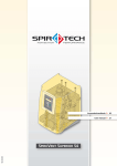
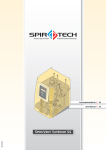
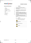
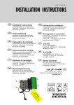
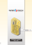
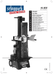
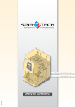
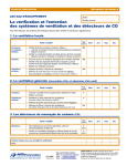
OBJ_BUCH-45-001.book Page 3 Tuesday, June 14, 2011 10:56 AM
1
Svenska
Användarmanual
INNEHÅLLSFÖRTECKNING
FÖRORD
Denna användarhandbok behandlar installation,
driftsättning och drift av Spirovent Superior av typerna
S6A, S6A-R och S6A-R 2P.
/i
1
Förord
3
2
Inledning
4
3
Tekniska specifikationer
6
4
Säkerhet
8
5
Installation och driftsättning
9
6
Användning
15
7
Driftsfel
16
8
Underhåll
20
9
Garanti
22
10 CE-förklaring
22
Läs alltid anvisningarna noggrant före installation,
driftsättning och användning. Behåll anvisningarna för
framtida referens.
Alla rättigheter förbehållna. Ingen del av denna handbok
får mångfaldigas och/eller publiceras via Internet, med
tryck, fotokopia, mikrofilm eller på något annat sätt utan
föregående skriftligt tillstånd från Spirotech bv.
Denna handbok är sammanställd med största omsorg.
Om handboken ändå skulle innehålla någon felaktighet
kan Spirotech bv. inte hållas ansvarigt för detta.
1.1
Symboler
Inom anvisningarna används följande symboler:
Varning eller viktigt meddelande
Anmärkning
Risk för elchock
Risk för brännskada
Användarmanual - 1.2
Svenska
3
OBJ_BUCH-45-001.book Page 4 Tuesday, June 14, 2011 10:56 AM
2
INLEDNING
2.1
Översikt över enheten
V
U
A
T
B
S
C
R
D
E
R
Superior S6A
F
G
Q
H
P
I
O
J
N
K
M
L
Superior S6A-R 2P
A
B
C
D
E
F
G
H
I
J
K
L
M
N
4
SmartSwitch
Automatisk avluftare
Avgasningskärl
Intagsslang
Påfyllnadsanslutning (typ S6A-R och S6A-R 2P)
Avstängning bakom manometer
Skruv
Vattenflödesmätare
Nivåomkopplare (i kärlets botten)
Ställbar intagsventil
Temperaturkännare
Reservpump (för typS6A-R 2P)
Tömningsanslutning (under kärlet)
Magnetventil
Superior S6A-R
O
P
Q
R
S
T
U
V
Svenska
Huvudpump
Ställbar returventil
Tryckkännare
Tryckomkopplare
Tryckmätare
Styrmodul
Returslang
Hölje
Användarmanual - 1.2
OBJ_BUCH-45-001.book Page 5 Tuesday, June 14, 2011 10:56 AM
2.2
Funktion
/i
Nedanstående figur ger en schematisk återgivning av
enhetens funktion. Bokstäverna korresponderar med
huvudfiguren på föregående sida.
TT
D
K
J
PS
A
PI
B
N
S
F
R
PS
C
M
LS
I
U P
S6A
O
TT
D
M
K
J
PS
A
E
FT
N
PI
B
F
H
R
Q
N
S
PS
C
M
PT
LS
U
S6A-R
P
O
D
I
TT
M
K
J
A
PS
N
FT
H
B
N
S
F
M
R
Q
PI
PS
C
M
L
PT
LS
S6A-R 2P
Användarmanual - 1.2
U
I
P
O
Svenska
M
5
OBJ_BUCH-45-001.book Page 6 Tuesday, June 14, 2011 10:56 AM
2.2.1
Allmänt
Superior är en helautomatisk vakuumavgasare för
vätskefyllda anläggningar. Vätskan innehåller lösta och
olösta gaser. Enhetens funktion att avlägsna dessa gaser
från anläggningen tills koncentrationen av olösta gaser
når ett absolut minimum. På så sätt elimineras problem
som kan uppstå till följd av gaser i systemet.
Enheten ska användas inom gränserna som anges i de
tekniska specifikationerna, avsnitt 3.
VARNING
Kontakta alltid din leverantör om du
tvivlar.
Om systemvätskan är svårt förorenad
måste en smutsseparator monteras i
anläggningens huvudreturlinje.
•
•
Typen S6A-R 2P har även en reservpump. Vid störning i
huvudpumpen, övertar reservpumpen huvudpumpens
påfyllnadsfunktion så att systemtrycket garanterat
bibehålls.
2.2.2
Avgasning
Enheten startar dagligen med avgasningsprocessen vid
en tidpunkt som användaren ställer in. Processen har två
faser:
1
Spolfasen: Vätskan strömmar från anläggningen
genom magnetventilen (N) till kärlet (C). Pumpen
(O) pumpar kontinuerligt (den avgasade) vätskan
från kärlet till anläggningen. Här kommer den
avgasade vätskan åter att absorbera gaser.
2
Vakuumfasen: Magnetventilen (N) stängs
regelbundet, vilket startar vakuumfasen. Den
kontinuerligt löpande pumpen (O) skapar ett
undertryck i kärlet (C). Genom undertrycket slipper
de lösta gaserna ut ur vätskan och samlas Skall tas
bort upptill i kärlet. Magnetventilen öppnas igen,
vilket startar nästa spolfas. Gaserna som samlas i
kärlet släpps ut ur systemet via den automatiska
avluftaren (B). SmartSwitch-omkopplaren (A) i
styrmodulen sörjer för att avgasningen avbryts så
snart halten av lösta gaser har nått miniminivån.
2.4
Leveransens omfång
1x SpiroVent Superior
1x Användarhandbok
1x Backventil (tillval)
•
•
•
3
TEKNISKA SPECIFIKATIONER
3.1
Dimensioner
880
Typerna S6A-R och S6A-R 2P har en integrerad
påfyllnadsautomat. Påfyllnadsautomaten bibehåller ett
konstant tryck i anläggningen Härvid avgasar enheten
vätskan om det behövs. Enheten kan även fylla hela
anläggningen med avgasad vätska.
350
590
/i
Höjd [mm]
Bredd [mm]
Djup [mm]
880
590
350
2.2.3
(På)fyllning
Enheter av typ S6A-R och S6A-R 2P kontrollerar ständigt
systemtrycket. Påfyllnadsprocessen startar och stannar
automatiskt vid inställda värden. Enheten kan även
användas för automatisk fyllning av systemet med
avgasad vätska.
2.3
Driftsförhållanden
Enheten är lämpad för bruk i system fyllda med rent
vatten eller en blandning av vatten med maximalt 40%
glykol. Bruk tillsammans med andra vätskor kan leda till
ohjälplig skada.
6
Svenska
Användarmanual - 1.2
OBJ_BUCH-45-001.book Page 7 Tuesday, June 14, 2011 10:56 AM
3.2
Allmänna specifikationer
/i
S6A
S6A-R
S6A-R 2P
Max. systemvolym
150 - 300 m3
150 - 300 m3
150 - 300 m3
Tomvikt
57 kg
59 kg
67 kg
Volym avgasningskärl
8l
8l
8l
Intagsanslutning
Lekare G¾" hona
Lekare G¾" hona
Lekare G¾" hona
Utloppsanslutning
Lekare G¾" hona
Lekare G¾" hona
Lekare G¾" hona
Tömningsanslutning
Lekare G¾" hane
Lekare G¾" hane
Lekare G¾" hane
Bullernivå
Ca. 57 dB(a)
Ca. 57 dB(a)
Ca. 57 dB(a)
Påfyllnadsanslutning
gäller ej
Lekare G¾" hona
Lekare G¾" hona
S6A
S6A-R
S6A-R 2P
Matningsspänning
230 V ± 10% / 50 eller 60
Hz
230 V ± 10% / 50 eller 60
Hz
230 V ± 10% / 50 eller 60
Hz
Upptagen effekt
800 W
800 W
1300 W
Nominell strömstyrka
3,5 A
3,5 A
5,5 A
Startström
2,6*nominell strömstyrka
2,6*nominell strömstyrka
2,6*nominell strömstyrka
Säkring
10 A / 3.15 A(T)
10 A / 3.15 A(T)
10 A / 3.15 A(T)
Skyddsklass
IP X4D
IP X4D
IP X4D
Max. belastning
potentialfria kontakter
24 V / 1 A
24 V / 1 A
24 V / 1 A
Matningsspänningen till
BMS-kontroll
(spänning i BMS)
24 VAC
24 VAC
24 VAC
Matningsspänning extern
påfyllnadssignal
(tillhandahållen spänning)
gäller ej
5 Vdc
5 Vdc
S6A
S6A-R
S6A-R 2P
Systemtryck
1 - 6 bar
1 - 6 bar
1 - 6 bar
Omgivningstemperatur
0 - 40 °C
0 - 40 °C
0 - 40 °C
Maximalt
komprimeringstryck
10 bar
10 bar
10 bar
Fyllnadsflöde
gäller ej
Se diagram i § 6.1
Se diagram i § 6.1
Temperatur systemvätska
0 - 90 °C.
0 - 90 °C
0 - 90 °C
Påfyllnadstryck
0 - 6 bar
0 - 6 bar
0 - 6 bar
Temperatur
påfyllnadsvätska
gäller ej
0 - 70 °C
0 - 70 °C
3.3
Elektriska specifikationer
/i
3.4
Övriga specifikationer
/i
(med kranen bakom
tryckmätaren stängd)
Användarmanual - 1.2
Svenska
7
OBJ_BUCH-45-001.book Page 8 Tuesday, June 14, 2011 10:56 AM
3.5
Building Management System
(BMS)
/i
Enheten är försedd med externa kontakter för
kommunikation med ett BMS. Detta BMS måste ha
spänningen 24 VAC.
Signal
S6A
S6A-R
S6A-R 2P
Enheten i drift
Potentialfri
Potentialfri
Potentialfri
Störning i enheten
Potentialfri
Potentialfri
Potentialfri
Frigivning/stopp av enheten 24 VAC
24 VAC
24 VAC
Påfyllning av BMS
24 VAC
24 VAC
4
gäller ej
SÄKERHET
4.2
Typskylt
A
VARNING
•
•
B
C
Installation och underhåll av enheten får
endast utföras av befogad personal.
Stäng av spänningen och gör enheten
tryckfri innan arbetet påbörjas.
D
E
SPIROVENT SUPERIOR
Article-No.:
Type:
Power input:
Voltage / Frequency:
IP class:
Pressure PS:
Temperature TS:
F
VARNING
Det befinner sig heta delar under höljet. Låt
enheten svalna innan ingreppet påbörjas.
4.1
Year of manufacture:
G
Weight:
Spirotech bv - The Netherlands
H
I
CE-markering
Enheten är CE-märkt Detta innebär att den har
konstruerats, tillverkats och testats enligt gällande
säkerhets- och hälsobestämmelser.
Så länge anvisningarna i handboken iakttas kan enheten
användas och skötas utan risk.
8
Serial no.:
A
B
C
D
E
F
G
H
I
Svenska
Enhetens typ
Upptagen effekt
Matningsspänning
Skyddsklass
Systemtryck
Systemtemperatur
Serienummer
Byggnadsår
Vikt
Användarmanual - 1.2
OBJ_BUCH-45-001.book Page 9 Tuesday, June 14, 2011 10:56 AM
5
INSTALLATION OCH
DRIFTSÄTTNING
5.1
•
•
•
•
5.3
OBS!
Installationskrav
•
Enheten skall installeras på en frostfri, väl ventilerad
plats
Anslut enheten elektriskt till ett 230 V / 50 -60 Hzuttag.
Kontrollera att expansionssystemet har rätt
dimensioner. Vattenförflyttningen i enheten kan
orsaka tryckändringar i anläggningen.
Det måste finnas ett övertryck i anläggningen.
Detta förhindrar att luft tränger in spontant.
5.2
Installation och montering.
•
Installera enheten enligt lokalt gällande
föreskrifter och bestämmelser.
Installera enheten som en ett delflöde
parallellt med huvudledningen.
ANMÄRKNING
•
Uppackning
•
VARNING
Vinscha inte enheten när den inte är
förpackad. Användning av lyftband, kedjor
och krokar kan orsaka ohjälpliga skador.
•
Enheten bör helst installeras på den
punkt i anläggningen som har den
lägsta temperaturen. Här har vätskan
den högsta halten av lösta gaser.
Se vid installationen till att
manöverpanelen alltid är lätt tillgänglig.
Se till att du upprätthåller ett minimalt
avstånd för service och reparation som
indikeras i ritningen nedan.
•
Enheten levereras på en pall.
1.
Avlägsna förpackningen.
A
B
60cm
60cm
A C
2.
3.
4.
Lossa de två skruvarna (A).
Avlägsna höljet (B) från enheten.
Flytta enheten med två personer till
installationsplatsen. Lyft enheten i handtagen (C).
Användarmanual - 1.2
Svenska
9
OBJ_BUCH-45-001.book Page 10 Tuesday, June 14, 2011 10:56 AM
5.3.1
Montering
A
A Ø10
D
B
C
E F
G
B Ø10
1.
2.
Väggmontering: Montera enheten på väggen med
hålen (A). Se till att fästet kan bära den fyllda
enheten (tomvikt + 10 kg).
Golvmontering: Ställ enheten på ett plant
underlag. Fäst enheten vid golvet med hålen (B).
5.3.2
ANMÄRKNING
Sett från volymflödets riktning är den första
grenledningen intaget till enheten.
3.
4.
Installation
Mekaniskt
Koppla ledningen (A) till den flexibla returslangen
(D).
Koppla ledningen (B) till den flexibla tilloppsslangen
(C).
Hos typerna S6A-R och S6A-R 2P:
1.
Montera en kran (F) och en backventil (E) i
påfyllnadsvätskans matningsledning.
2.
Koppla matningsledningen till enhetens
påfyllnadsanslutning (G).
> 500mm
A
B
OBS!
•
A
•
B
•
1.
2.
Använd en lokalt godkänd backventil. En
backventil kan medfölja leveransen som
tillval.
Se till att trycket i påfyllnadsledningen är
lägre än systemtrycket. Detta förebygger
oönskad påfyllning vid störning i
påfyllnadsledningen.
Se till att ledningarna lämnar enheten på
baksidan.
Anlägg två ¾" grenledningar (A) på sidan av
huvudtransportledningen. Deras inbördes avstånd
ska vara minst 500 mm.
Montera en ventil (B) i varje gren. Skall tas bort.
OBS!
Kontrollera att kranarna är öppna innan
enheten sätts i drift.
10
Svenska
Användarmanual - 1.2
OBJ_BUCH-45-001.book Page 11 Tuesday, June 14, 2011 10:56 AM
Elektriskt
1
2
L
OBS!
•
•
•
•
Använd helst ett vägguttag för enhetens
strömförsörjning. Detta måste alltid vara
åtkomligt.
Montera en flerpols huvudströmbrytare
(kontaktöppning >= 3mm) om enheten
kopplas direkt till strömförsörjningen.
Använd matningskablar med rätt
dimensioner.
Byt alltid ut en trasig säkring mot en
säkring med samma värde. Se §3.3.
PE
N
L1
T >70°C
3
F7 F6 F5 F8 F1
A
J21
J16
J20
F2
J2
1 2
J2 1
0 8
1
6
J1 1
6
1.
2.
Drag en 3-polig matningskabel genom lekaren (A).
Drag en 3-polig matningskabel till kontakt J16.
4
/i
kontakt
kontakt
stift
anslutning
J20
1 och 2
Enhet klar för bruk
3 och 4
Fel
5 och 6
Till/från
7 och 8
Påfyllning1)
1 och 2
Påfyllning1)
J21
1) gäller för typerna S6A-R och S6A-R 2P.
Användarmanual - 1.2
Svenska
11
OBJ_BUCH-45-001.book Page 12 Tuesday, June 14, 2011 10:56 AM
3.
5.4.2
Om en BMS används, anslut då en BMS-kabel till
kontakt J20.
Start
Hos typerna S6A-R och S6A-R 2P:
1.
Om en extern anordning styr påfyllningen, anslut
då en kabel till kontakt J21.
5.4
Driftsättning
5.4.1
Förberedelser
A
B
C
E
F
C
I
D
H
E
G
F
D
A
G
B
1.
2.
3.
4.
Ställ in ventilerna (A och B) från läget "helt öppen"
enligt följande tabell.
Öppna kranen (C) bakom manometer (D).
Öppna kranarna (E och F) i in- och
utmatningsledningarna.
Öppna kranen (G) i påfyllnadsledningen.
A
B
C
D
E
F
G
H
I
OBS!
•
•
/i
Systemtry
ck [bar]
Systemtryck
[bar]
Medium:
vatten
Medium:
vatten/
glykol
Position
ställkran
tillopp (B)
Position
ställkran
retur (A)
1-2
3
2
2-3
2.5
2.5
3-4
2.25
6
4-5
2
6
5-6
1.75
6
1-2
6
2
2-3
6
2.5
3-6
6
6
Till/från
Display
Statusrapport under drift / OK
Upp
Bekräfta / Enter
Meny
Ned
Upphäv / Exit
Statusrapport fel
Startsekvensen startar automatiskt
första gången enheten kopplas in.
Tryck på EXIT för att gå tillbaka ett steg i
menyn under programmering.
Följ nedanstående procedurer för att föra in erfordrade
parametrar.
Ställ in datum och tid
1.
Tryck på ON/OFF.
2.
Välj ett språk med S och T. Tryck på ENTER.
3.
Ställ in datum med S och T. Tryck på ENTER.
4.
Ställ in datum med S och T. Tryck på ENTER.
5.
Ställ in tiden med S och T. Tryck på ENTER.
ANMÄRKNING
Trycket i kärlet under spolningsfasen ska öka
från vakuum upp till övertryck på 10 sekunder.
Om det tar längre tid, vrid då
justeringsventilen (B) till helt öppen och sedan
tillbaka till läge ¼ högre än det aktuella läget.
12
Svenska
Användarmanual - 1.2
OBJ_BUCH-45-001.book Page 13 Tuesday, June 14, 2011 10:56 AM
Kontrollera funktionen
Fyllning av enheten
D
C
A
A
B
D
1.
2.
3.
4.
5.
6.
7.
8.
Tryck två gånger på ENTER. Enheten börjar fyllas.
Vänta i 20 sekunder tills Initial fill busy
raderas.
Lossa avluftningsskruven (A) ett par varv och dra åt
den igen när det inte längre kommer ut luft.
Upprepa stegen 1 - 3 tills vatten börjar komma ut
genom avluftningsskruven vid steg 3.
Hos typen S6A-R 2P måste även reservpumpen
avluftas.
Tryck två gånger på EXIT. Statusmenyn visar
meddelandet Err 7 när testning av
torrlöpningsskyddet har utförts med framgång.
Tryck på MENU. Välj Manual operation med T
och T. Tryck på ENTER.
Välj Reset med S och S. Tryck på ENTER.
ANMÄRKNING
Den gröna lysdioden "OK" anger att enheten
är klar för bruk. Som standard startar
avgasningen dagligen kl. 08:00.
1.
2.
3.
4.
Starta enheten manuellt, se § 5.5.2.
Kontrollera värdet på tryckmätaren (B). Detta ska
visa över- och undertryck växelvis.
Stäng kranen (A) bakom tryckmätaren (B).
Sätt tillbaka höljet (C) på enheten och sätt fast det
med de 2 skruvarna (D).
ANMÄRKNING
SmartSwitch-omkopplaren stänger
automatiskt av enheten när
koncentrationen av lösta gaser har nått
miniminivån.
5.5
Installation och drift
5.5.1
Installation
Ställ in användarparametrarna
1.
Tryck på MENU. Välj Settings med S och S. Tryck
på ENTER.
2.
Välj parametern som ska ändras med S och T.
Tryck på ENTER.
3.
Ändra inställningen med S och T. Tryck på ENTER.
4.
Upprepa vid behov steg 2 och 3.
5.
Tryck upprepat på EXIT för att återvända till
statusrapporten.
/i
Användarmanual - 1.2
Parameter
Beskrivning
Språk
Språk för skärmtexterna.
Date
Aktuellt datum.
Veckodag
Aktuell veckodag.
Time
Aktuell tidpunkt.
Auto start 1
Tid 1 för start av
avgasningsprocessen.
Auto start 2
Se Auto start 1.
Block. Tid dag 1
Tid när avgasningsprocessen ska
stoppas.
Svenska
13
OBJ_BUCH-45-001.book Page 14 Tuesday, June 14, 2011 10:56 AM
Parameter
Beskrivning
1.
Block. Tid dag 2
Se Block.time day 1.
2.
Block. tid vecka 3
Veckodagar då enheten inte skall
köras.
3.
Tryck på MENU. Välj User menu > Manual
operation med S och T. Tryck på ENTER.
Välj Manual operation > system fill med S
och T. Tryck på ENTER.
Välj Degassed eller Non degassed. Tryck på
ENTER.
Valda dagar markeras med en *.
När du har ändrat denna parameter
väljer du Save med S eller T.
Tryck på ENTER.
Block. Tid år 1
Period under året då enheten inte
skall köras.
Block.time year 2
-5
Se Block.time year 1.
Max. syst.
pressure 1)
Tryck varvid enheten stannar.
Nödv. Syst. tryck1) Tryck varvid påfyllnaden upphör.
Ställ in detta så lågt som möjligt
om påfyllnaden styrs av ett BMS
eller externa anordningar.
Påfyllnadstryck1)
Tryck varvid påfyllnaden startar.
Ställ in detta så lågt som möjligt
om påfyllnaden styrs av ett BMS
eller externa anordningar.
Påfyllnadslarm1)
Maximal vätskemängd som får
fyllas på per gång (0 - 2500 l; 0 =
avstängd).
Påfyll. Larm
efter1)
Kontinuerlig påfyllnadstid (0 - 255
min.; 0 = avstängd).
Max. refill freq.1)
Maximalt antal gånger per dag som
återfyllnad är tillåtet
(0 - 10 gånger; 0 = avstängd).
1) gäller för typerna S6A-R och S6A-R 2P.
5.5.2
Manuell drift
ANMÄRKNING
Om processen har stängts av manuellt, måste
den kopplas in igen manuellt.
1.
2.
Tryck på MENU. Välj User menu > Manual
operation med S och T. Tryck på ENTER.
Välj Manual operation start eller Manual
operation stop med S och TT. Tryck på ENTER.
5.5.3
Fyllning av anläggningen
Gäller för typerna S6A-R och S6A-R 2P.
5.5.4
Inkoppling på nytt
Följ nedanstående procedur när enheten har varit
avstängd.
1.
Ställ in ställkranarna från positionen "helt öppen"
enligt tabellen i § 5.4.1.
2.
Tryck på ON/OFF.
3.
Tryck två gånger på ENTER. Enheten börjar fyllas.
4.
Vänta i 20 sekunder tills Initial fill busy
raderas.
5.
Lossa avluftningsskruven (A, se figur på föregående
sida) ett par varv och dra åt den igen när det inte
längre kommer ut luft.
6.
Upprepa stegen 3 - 5 tills vatten börjar komma ut
genom avluftningsskruven vid steg 5.
7.
Hos typen S6A-R 2P måste även reservpumpen
avluftas.
8.
Tryck två gånger på EXIT. Statusmenyn visar
meddelandet Err 7 när testning av
torrlöpningsskyddet har utförts med framgång.
9.
Tryck på MENU. Välj Manual operation med T
och T. Tryck på ENTER.
10. Välj Reset med S och S. Tryck på ENTER.
ANMÄRKNING
Den gröna lysdioden "OK" anger att enheten
är klar för bruk.
5.5.5
Avläsning av minnet
Under drift lagras följande data i minnet:
•
Sammanräknade driftstimmar
•
Avgasningshistoria
•
Felhistorik
•
Påfyllnadshistorik (endast hos typerna S6A-R och
S6A-R 2P).
Minnet kan avläsas så här:
1.
Tryck på MENU. Välj User menu > History med
SS och S. Tryck på ENTER.
2.
Välj Fault history eller Operation history
med S och T. Tryck på ENTER.
3.
Välj en punkt med S och T. Tryck på ENTER.
4.
Tryck upprepat på EXIT för att återvända till
statusrapporten.
ANMÄRKNING
Enheten fyller även anläggningen med vätska
(avgasad eller ej). När det önskade
systemtrycket har uppnåtts, går enheten
automatiskt till tillståndet standby.
14
Svenska
Användarmanual - 1.2
OBJ_BUCH-45-001.book Page 15 Tuesday, June 14, 2011 10:56 AM
5.5.6
Avläsning av data
Följande allmänna uppgifter har lagrats i enhetens
minne:
•
Apparattyp
•
Mjukvaruversion
•
Installationsdatum.
Dessa allmänna data kan avläsas så här:
1.
Tryck på MENU. Välj User menu > General info
med S och S. Tryck på ENTER.
2.
Välj en punkt med S och T. Tryck på ENTER.
3.
Tryck upprepat på EXIT för att återvända till
statusrapporten.
•
•
Vid låga vätsketemperaturer kan kondens uppstå på
vissa platser. Kondensvätskan töms ut genom
öppningarna i ramen.
Hos typerna S6A-R och S6A-R 2P:
Den tillfogade vätskemängden (B) beror på
skillnaden (A) mellan systemtrycket och
påfyllnadsvattnets tryck.
B
600
6
ANVÄNDNING
500
6.1
Allmänt
300
400
200
Displayens belysning bländas automatiskt ned när
ingen tangent har tryckts in under 5 minuter. Tryck
på en tangent för att tända ljuset.
När processen stoppas, startar en stopprocedur
som ser till att enheten stannar i en säker situation
(övertryck).
När en pump inte har löpt under 96 timmar, körs ett
automatiskt pumptest vid nästa Auto start.
Tryck på ON/OFF för att stänga av enheten. Tryck åter
på ON/OFF för att starta enheten igen.
•
•
•
•
6.2
100
0
0
1
2
3
4
5
A
A
B
Systemtryck - tryckvattenledning (bar)
Flöde (l/tim)
Statusrapporter
/i
Rapport
Beskrivning
Lysdiod
Auto pump test
Enheten kör ett pumptest.
Grön
End degassing
Stopproceduren är igång.
Grön
Avgasning
Avgasningsproceduren är igång.
Grön
Process stopp
Enheten har stoppats manuellt.
Ingen
Standby
Enheten väntar på en startsignal.
Grön
Stoppad av BMS
BMS har stoppat enheten. Efter frigivning från BMS måste
enheten startas manuellt.
Ingen
Fel
Enheten har stoppat p.g.a. ett fel. Åtgärda felet innan enheten
återställs, se § 7.4. Enheten kopplas till ett av ovanstående
tillstånd.
Röd
Slut påfyllnad
End systemfill
Refill (endast hos S6A- Enheten fyller på vätska.
R och S6A-R 2P)
Fyllnadssystem
(endast hos S6A-R och
S6A-R 2P)
Användarmanual - 1.2
Grön
Anläggningen fylls med vätska.
Svenska
Grön
15
OBJ_BUCH-45-001.book Page 16 Tuesday, June 14, 2011 10:56 AM
7
DRIFTSFEL
7.1
Åtgärder vid driftsfel
7.2
Tagning ur drift
A
B
VARNING
•
•
•
Varsko alltid installatören vid driftsfel.
Stäng av spänningen och gör enheten
tryckfri innan ingreppet påbörjas, se
§7.2.
Ett tryck på ON/OFF stänger inte av
enhetens spänning.
E
F
VARNING
Det befinner sig heta delar under höljet. Låt
enheten svalna innan ingreppet påbörjas.
C
D H
1.
ANMÄRKNING
Vid driftsfel lyser den röda lysdioden.
Felrapporten visas på displayen.
2.
ANMÄRKNING
Hos typerna S6A-R och S6A-R 2P avgörs felets
allvar om hela enheten eller en del av enheten
stängs av. Vid delvis avstängning förblir
påfyllnadsprocessen aktiv. I detta fall lyser
både den röda och den gröna lysdioden.
1.
2.
3.
4.
16
3.
4.
5.
6.
Lokalisera felet med hjälp av felsökningstabellen,
se § 7.3.
Tag enheten ur drift om det behövs,
se § 7.2.
Åtgärda felet.
Återställ enheten, se §7.4 eller sätt den åter i drift,
se §5.5.4.
Svenska
G
Dra ut kontakten ur vägguttaget eller stäng av
huvudströmbrytaren. Se till att spänningen inte kan
kopplas in av misstag.
Stäng kranarna (A) och/eller (C) i tilloppsledningen
och (B) och/eller (D) i returledningen.
Stäng i tillämpliga fall även kranen (E) i
påfyllnadsledningen.
Koppla en tömningsledning (H) till
tömningsanslutningen (G).
Töm enheten genom tömningsanslutningen (G).
Öppna avluftningsskruven på huvudpumpen för att
tömma enheten fullständigt. Se figuren i § 5.4.2.
Användarmanual - 1.2
OBJ_BUCH-45-001.book Page 17 Tuesday, June 14, 2011 10:56 AM
7.3
Felsökningstabell
Bokstäverna korresponderar med huvudfiguren i § 2.1. En
översikt över reservdelarna kan återfinnas i § 8.2.
Allmänt
Problem
Möjlig orsak
Årgärd
Err 3 Syst.temp. too low
Systemvätskans temperatur är < 0 °C. Sörj för en temperatur på > 0 °C.
Risk för frysning föreligger.
Err 4 Syst.temp. too high
Systemvätskans temperatur är > 90
°C.
Sörj för en temperatur på < 90 °C.
Magnetventilen (N) i
tilloppsledningen öppnas ej.
Byt ut (en del av) magnetventilen.
En kran i tilloppsledningen är stängd.
Öppna kranen.
Tilloppsledningen är täppt.
Avlägsna blockeringen.
Tryckomkopplaren (R) är defekt.
Byt ut tryckomkopplaren.
Kritisk inställning för justering av
ventilinloppet (J).
Vrid justeringsventil ¼ position uppåt
(från helt öppen).
Kabel till tryckbrytare (R) bortkopplad
eller avbruten.
Byt ut kabeln. Byt ut kabelflänsarna.
Justeringsventilens (P) inlopp har inte
ställts in korrekt.
Vrid justeringsventilen för utloppet
till den korrekta positionen (se § 5.4.1
).
En av magnetventilerna (N) stängs ej.
Rengör ventilens insida. Om så
erfordras, byt ut (en del av)
magnetventilen.
Kranen i returledningen är stängd.
Öppna kranen.
Returledningen är täppt.
Avlägsna blockeringen.
Pumpen (O) löper ej.
Kontrollera pumpen. Syna och byt ut
pumpsäkringen i styrmodulen.
Tryckomkopplaren (R) är defekt.
Byt ut tryckomkopplaren.
Den automatiska avluftaren (B) är
tilltäppt.
Byt ut den automatiska avluftaren.
Den automatiska avluftaren (B) är
defekt eller blockerad.
Byt ut den automatiska avluftaren.
Kärlet är inte fyllt.
Fyll kärlet (se § 5.5.4).
Nivåomkopplaren (I) är defekt.
Byt ut nivåomkopplaren.
Kontrollera kabelanslutning.
Byt ut kabeln.
Risk för kokning föreligger.
Err 5 Entrance flow
Flödet i tilloppsledningen är blockerat
1).
Err 6 Flow
Flödet i returledningen blockerat 1).
Err 7 Fluid lack vessel
Risk för torrlöpning föreligger,
vätskan i kärlet står på miniminivån.
Kabel till nivåstift frånkopplad eller
avbruten.
Användarmanual - 1.2
Svenska
17
OBJ_BUCH-45-001.book Page 18 Tuesday, June 14, 2011 10:56 AM
Allmänt
Problem
Möjlig orsak
Årgärd
Enheten löper kontinuerligt och
stängs inte av automatiskt.
Halten av lösta gaser har ännu inte
nått minimum.
Kontrollera om gaser möjligen kan
tränga in.
SmartSwitch-omkopplaren (A) är
defekt.
Koppla lös slangen på den
automatiska avluftaren. Byt ut
SmartSwitch-omkopplaren om
enheten inte stängs av efter 10
minuter.
Den automatiska avluftaren (B) är
defekt.
Kontrollera om det slipper ut gas
genom ventilen. Byt ut den
automatiska avluftaren om ingen gas
slipper ut.
SmartSwitch-omkopplaren (A) är
defekt.
Kontrollera om det slipper ut gas
genom ventilen. Byt ut SmartSwitchomkopplaren om gas slipper ut.
Den automatiska avluftaren (B) är
defekt.
Byt ut den automatiska avluftaren.
Kontrollhårdvara eller programvara är
defekt.
Byt ut styrmodulen.
SmartSwitch-omkopplaren verkar inte
fungera1).
Enheten löper maximalt 10 min. per
avgasningsperiod. Gaser blir kvar i
anläggningen.
SmartSwitch-omkopplaren verkar inte
fungera.1)
Err 99 Fel i styrmodulen.
1) Påfyllnadsfunktionen förblir aktiv, detta gäller för typ S6A-R och S6A-R 2P.
Särskilt för typerna S6A-R och S6A-R 2P
Problem
Möjlig orsak
Årgärd
Err 1 Psystem too low
Ett fel i anläggningen.
Sörj för ett systemtryck på > 1 bar.
Läckage föreligger i anläggningen.
Reparera läckan.
Tryckkännaren (Q) är defekt.
Byt ut tryckkännaren.
Err 2 Psystem too high
Ett fel i anläggningen.
Sörj för ett systemtryck som är lägre
än ställvärdet.
Systemtrycket överskrider inställt
maximum.
Ställvärdet är för lågt.
Höj ställvärdet.
Tryckkännaren (Q) är defekt.
Byt ut tryckkännaren.
Systemtrycket är lägre än 1 bar.
En kran i utloppsledningen är stängd. Öppna kranen.
Err 10 Refill flow too low
Ingen eller bristfällig tillförsel av
påfyllnadsvätska1).
Err 11 Refill valve
Utloppsledningen (S) är tilltäppt.
Avlägsna igentäppningen.
En kran i påfyllnadsledningen är
(delvis) stängd.
Öppna kranen.
Magnetventilen (N) i
påfyllnadsledningen öppnas ej.
Byt ut (en del av) magnetventilen.
Påfyllnadsledningen är täppt.
Avlägsna blockeringen.
Vattenflödesmätaren (H) är defekt.
Byt ut vattenflödesmätaren.
Magnetventilen (N) i
påfyllnadsledningen stängs ej.
Byt ut (en del av) magnetventilen.
Oönskad tillförsel av
påfyllnadsvätska. Påfyllnaden upphör
ej.
18
Svenska
Användarmanual - 1.2
OBJ_BUCH-45-001.book Page 19 Tuesday, June 14, 2011 10:56 AM
Särskilt för typerna S6A-R och S6A-R 2P
Problem
Möjlig orsak
Årgärd
Err 13 Refill freq. too high
Läckage föreligger i anläggningen.
Reparera läckan.
Kontrollera inställningen Max.
refill freq.
Påfyllnad sker för ofta.
Err 14 Refill time too high
Läckage föreligger i anläggningen.
Kontrollera inställningen Alarm
refill after:
Påfyllnaden tar för lång tid.
Err 15 Refill quantity
Reparera läckan.
Läckage föreligger i anläggningen.
Reparera läckan.
Kontrollera inställningen Alarm
refill
För mycket vätska fylls på.
1) Påfyllnadsfunktionen förblir aktiv, detta gäller för typ S6A-R och S6A-R 2P.
7.4
1.
2.
Återställning av enheten
Tryck på MENU. Välj User menu > Manual
operation med S och T. Tryck på ENTER.
Välj Manual operation reset med T och T.
Tryck på ENTER.
Användarmanual - 1.2
Svenska
19
OBJ_BUCH-45-001.book Page 20 Tuesday, June 14, 2011 10:56 AM
8
UNDERHÅLL
8.1
Periodiskt underhåll
1.
2.
Byt ut den automatiska avluftaren vartannat år.
Byt ut insatsen i magnetventilerna (N) årligen.
8.2
Reservdelar
Bokstäverna korresponderar med huvudfiguren i § 2.1.
Artikelnummer
Bokstav
/i
Beskrivning
15.552
O
Axelpackning för pump typ CR1-13/1-9 AAA HQQE
15.553
O
Packningssats för pump typ CR1-9 och CR1-13
15.554
O
Kondensator för pump typ CR1-13
15.790
O
Kondensator för pump typ CR1-9
15.510
O
Pump typ CR1-13 AAA HQQE (50 Hz)
15.511
O
Pump typ CR1-9 AAA HQQE (60 Hz)
R70.675
V
Hölje
12.023
N
Magnetventil (exklusive spole)
12.022
N
Spole för magnetventil
15.765
N
Insats för magnetventil
12.021
S
Tryckmätare
R17.889
-
Återfyllning av backventil
R17.886
B
Automatisk avluftare
13.468
T
Tryckomkopplare
R18.091A05
T
Styrmodul (S6A)
R18.091A06
T
Styrmodul (S6A-R)
R18.091A07
T
Styrmodul (S6A-R 2P)
15.516
K
Temperaturkännare
R17.888
A
SmartSwitch
15.518
J, P
13.466
I
Nivåomkopplare
15.519
H
Vattenflödesmätare (S6A-R och S6A-R 2P)
15.520
Q
Tryckkännare (S6A-R och S6A-R 2P)
15.521
L
Pump typ PSAM70/A (S6A-R 2P) (50 Hz)
15.522
L
Pump typ PSAM706/A (S6A-R 2P) (60 Hz)
20
Ställkran
Svenska
Användarmanual - 1.2
OBJ_BUCH-45-001.book Page 21 Tuesday, June 14, 2011 10:56 AM
8.3
Underhållslista
/i
Typ:
Serienummer:
Installationsdatum.:
Installerad av firma:
Installerad av tekniker:
Inspektionsdatum:
Tekniker:
Initialer:
Tekniker:
Initialer:
Tekniker:
Initialer:
Tekniker:
Initialer:
Tekniker:
Initialer:
Tekniker:
Initialer:
Typ av underhåll:
Inspektionsdatum:
Typ av underhåll:
Inspektionsdatum:
Typ av underhåll:
Inspektionsdatum:
Typ av underhåll:
Inspektionsdatum:
Typ av underhåll:
Inspektionsdatum:
Typ av underhåll:
Användarmanual - 1.2
Svenska
21
OBJ_BUCH-45-001.book Page 22 Tuesday, June 14, 2011 10:56 AM
9
GARANTI
9.1
Garantivillkor
•
•
•
Garantin förfaller i fall av felaktig installation,
okunnigt bruk och/eller om obefogad personal
försöker utföra reparationer.
Följdskada täcks inte av garantin.
Garantin för Spirotechs produkter gäller till 2 år
efter inköpsdatum.
10
CE-FÖRKLARING
10.1
Förklaring om överensstämmelse
/i
22
Svenska
Användarmanual - 1.2
OBJ_BUCH-45-001.book Page 23 Tuesday, June 14, 2011 10:56 AM
1
English
User manual
TABLE OF CONTENTS
/i
1
Preface
23
2
Introduction
24
3
Technical specifications
26
4
Safety
28
5
Installation and commissioning
29
6
Use
35
7
Failures
36
8
Maintenance
40
9
Guarantee
42
10 CE statement
42
PREFACE
This user manual involves the installation, commissioning
and operation of the SpiroVent Superior of the types S6A,
S6A-R and S6A-R 2P.
Always carefully read the instructions before installation,
commissioning and operation. Keep the instructions for
future reference.
All rights reserved. No part of this manual may be
duplicated and/or made public through the Internet, by
means of printing, photocopying, microfilm or in any
other way without prior written permission from
Spirotech bv.
This manual has been composed with the utmost care.
Should, however, this manual contain any inaccuracies,
Spirotech bv cannot be held responsible for this.
1.1
Symbols
Throughout the instructions the following symbols are
used:
Warning or important note
Note
Risk of electric shock
Risk of burning
User manual - 1.2
English
23
OBJ_BUCH-45-001.book Page 24 Tuesday, June 14, 2011 10:56 AM
2
INTRODUCTION
2.1
Overview of the unit
V
U
A
T
B
S
C
R
D
E
R
Superior S6A
F
G
Q
H
P
I
O
J
N
K
M
L
Superior S6A-R 2P
A
B
C
D
E
F
G
H
I
J
K
L
M
N
24
SmartSwitch
Automatic air vent
Deaeration vessel
Inlet hose
Refill connection (types S6A-R and S6A-R 2P)
Valve behind pressure gauge
Screw
Water flow meter
Level switch (in bottom of vessel)
Adjustable inlet valve
Temperature sensor
Back-up pump (for type S6A-R 2P)
Drain connection (under the vessel)
Solenoid valve
Superior S6A-R
O
P
Q
R
S
T
U
V
English
Main pump
Adjustable outlet valve
Pressure sensor
Pressure switch
Pressure gauge
Control unit
Outlet hose
Cover
User manual - 1.2
OBJ_BUCH-45-001.book Page 25 Tuesday, June 14, 2011 10:56 AM
2.2
Operation
/i
The figure below schematically shows the operation of
the unit. The letter indications comply with the main
figure on the previous page.
TT
D
K
J
PS
A
PI
B
N
S
F
R
PS
C
M
LS
I
U P
S6A
O
TT
D
M
K
J
PS
A
E
FT
N
PI
B
F
H
R
Q
N
S
PS
C
M
PT
LS
U
S6A-R
P
O
D
I
TT
M
K
J
A
PS
N
FT
H
B
N
S
F
M
R
Q
PI
PS
C
M
L
PT
LS
S6A-R 2P
User manual - 1.2
U
I
P
O
English
M
25
OBJ_BUCH-45-001.book Page 26 Tuesday, June 14, 2011 10:56 AM
2.2.1
General
The Superior is a fully automatic vacuum degasser for
installations filled with fluid. The fluid contains dissolved
and undissolved gases. The function of the unit is to
remove these gases from the installation until the
concentration of undissolved gases has reached an
absolute minimum. Problems caused by gases in the
installation are thus eliminated.
The types S6A-R and S6A-R 2P have an integrated refill
automat. The refill automat maintains continuous
pressure in the installation. For this the unit adds
degassed fluid, if necessary. The unit can also fill the
entire installation with degassed fluid.
The unit should be used within the limits of the technical
specifications as given in chapter 3.
WARNING
•
2.4
2.2.2
Degassing
The unit starts up daily with the degassing process at a
time indicated by the user. The process has two phases:
1
The flushing phase: The fluid flows from the
installation through the solenoid valve (N) into the
vessel (C). The pump (O) continuously pumps the
(degassed) fluid from the vessel into the
installation. Here the degassed fluid absorbs gases
again.
2
The vacuum phase: The solenoid valve (N) regularly
closes, starting the vacuum phase. The continuously
running pump (O) provides underpressure in the
vessel (C). The underpressure causes the release of
the gases dissolved in the fluid, which are collected
at the top of the vessel. The solenoid valve (N)
opens again, starting a new flushing phase. The
gases collected in the vessel are removed from the
installation through the automatic air vent (B). The
SmartSwitch (A) in the control unit makes sure that
the degassing is stopped as soon as the content of
dissolved gases has reached the minimum level.
Scope of delivery
1x SpiroVent Superior
1x User manual
1x Non-return protection (optional)
•
•
•
3
TECHNICAL SPECIFICATIONS
3.1
Dimensions
880
The type S6A-R 2P also has a back-up pump. In case of a
break-down of the main pump, the back-up pump takes
over the refill function of the main pump, thus
guaranteeing the system pressure.
In case of doubt, always contact the
supplier.
In case of a heavily contaminated system
fluid, a dirt separator is to be installed in
the main return line of the installation.
•
350
590
/i
Height [mm]
Width [mm]
Depth [mm]
880
590
350
2.2.3
(Re)fill
The types S6A-R and S6A-R 2P of the unit constantly
check the installation pressure. The refill process starts
and stops automatically at the set values. The unit can
also be used to automatically fill the installation with
degassed fluid.
2.3
Operating conditions
The unit is suitable for use in systems filled with clean
water or mixtures of water with a maximum of 40%
glycol. Use in combination with other fluids may result in
irreparable damage.
26
English
User manual - 1.2
OBJ_BUCH-45-001.book Page 27 Tuesday, June 14, 2011 10:56 AM
3.2
General specifications
/i
S6A
S6A-R
S6A-R 2P
Max. system volume
150 - 300 m3
150 - 300 m3
150 - 300 m3
Empty weight
57 kg
59 kg
67 kg
Volume of degassing vessel
8l
8l
8l
Inlet connection
Swivel G¾” f.t.
Swivel G¾” f.t.
Swivel G¾” f.t.
Outlet connection
Swivel G¾” f.t.
Swivel G¾” f.t.
Swivel G¾” f.t.
Drain connection
Swivel G¾” m.t.
Swivel G¾” m.t.
Swivel G¾” m.t.
Noise level
Approx. 57 dB(a)
Approx. 57 dB(a)
Approx. 57 dB(a)
Refill connection
n/a
Swivel G¾” f.t.
Swivel G¾” f.t.
S6A
S6A-R
S6A-R 2P
Supply voltage
230 V ± 10% / 50 or 60 Hz
230 V ± 10% / 50 or 60 Hz
230 V ± 10% / 50 or 60 Hz
Absorbed power
800 W
800 W
1300 W
Nominal power
consumption
3.5 A
3.5 A
5.5 A
Starting current
2.6*nominal current
2.6*nominal current
2.6*nominal current
Protection
10 A / 3.15 A(T)
10 A / 3.15 A(T)
10 A / 3.15 A(T)
Protection class
IP X4D
IP X4D
IP X4D
Max. load of potential-free
contacts
24 V / 1 A
24 V / 1 A
24 V / 1 A
Supply voltage for BMS
control
(voltage of BMS)
24 Vac
24 Vac
24 Vac
Supply voltage of external
refill signal
(supplied voltage)
n/a
5 Vdc
5 Vdc
S6A
S6A-R
S6A-R 2P
System pressure
1 - 6 bar
1 - 6 bar
1 - 6 bar
Ambient temperature
0 - 40 °C
0 - 40 °C
0 - 40 °C
Maximum compression
pressure
10 bar
10 bar
10 bar
Refill flow
n/a
See graph in § 6.1
See graph in § 6.1
System fluid temperature
0 - 90 °C.
0 - 90 °C
0 - 90 °C
Refill pressure
0 - 6 bar
0 - 6 bar
0 - 6 bar
Refill fluid temperature
n/a
0 - 70 °C
0 - 70 °C
3.3
Electrical specifications
/i
3.4
Other specifications
/i
(with closed valve behind
pressure gauge)
User manual - 1.2
English
27
OBJ_BUCH-45-001.book Page 28 Tuesday, June 14, 2011 10:56 AM
3.5
Building Management System
(BMS)
/i
The unit has been provided with auxiliary contacts for
communication with a BMS. The BMS has to offer the 24
Vac voltage.
Signal
S6A
S6A-R
S6A-R 2P
Unit in operation
Potential-free
Potential-free
Potential-free
Unit failure
Potential-free
Potential-free
Potential-free
Unit release/stop
24 Vac
24 Vac
24 Vac
Refill by BMS
n/a
24 Vac
24 Vac
4
SAFETY
4.2
Type plate
A
WARNING
•
•
B
C
Installation and maintenance of the unit
should only be carried out by authorised
personnel.
Remove the voltage and pressure from
the unit before starting the activities.
D
E
SPIROVENT SUPERIOR
Article-No.:
Type:
Power input:
Voltage / Frequency:
IP class:
Pressure PS:
Temperature TS:
F
Serial no.:
Year of manufacture:
G
WARNING
There are hot parts below the cover. Let the
unit cool down before starting the activities.
Weight:
Spirotech bv - The Netherlands
H
I
4.1
CE marking
The unit has a CE marking. This means that the unit has
been designed, constructed and tested in compliance
with the current safety and health regulations.
Provided that the user manual is adhered to, the unit can
be safely used and maintained.
28
A
B
C
D
E
F
G
H
I
English
Type of the unit
Absorbed power
Supply voltage
Protection class
System pressure
System temperature
Serial number
Year of construction
Weight
User manual - 1.2
OBJ_BUCH-45-001.book Page 29 Tuesday, June 14, 2011 10:56 AM
5
INSTALLATION AND
COMMISSIONING
5.1
•
•
•
•
5.3
CAUTION
Installation conditions
•
Install the unit on a frost-free, well-ventilated place.
Electrically connect the unit to a 230 V / 50 -60 Hz
socket.
Make sure the expansion system has the proper
dimensions. The water displacement in the unit can
cause pressure variations in the installation.
There must be overpressure in the installation. This
prevents spontaneous aeration.
5.2
Installation and mounting
•
NOTE
•
Unpack
•
WARNING
Do not hoist the unit when unpacked. The use
of webbing slings, chains and hooks can
cause irreparable damage.
The unit is delivered on a pallet.
1.
Remove the packaging.
A
Install the unit in accordance with the
local guidelines and rules.
Install the unit as bypass on the main
transport line of the installation.
•
Preferably install the unit at the point in
the installation with the lowest
temperature. Here the most dissolved
gases are found in the fluid.
Make sure when installing that the
operating panel is always easily
accessible.
Make sure you maintain a minimal
distance for service and repair as
indicated in the below.
•
B
60cm
60cm
A C
2.
3.
4.
Loosen the 2 screws (A).
Remove the cover (B) from the unit.
Move the unit with two persons to the place of
installation. Lift the unit using the handles (C).
User manual - 1.2
English
29
OBJ_BUCH-45-001.book Page 30 Tuesday, June 14, 2011 10:56 AM
5.3.1
Mounting
A
A Ø10
D
B
C
E F
G
B Ø10
1.
2.
Wall mounting: Mount the unit on the wall using
the holes (A). Make sure that the mounting can
carry the filled unit (empty weight + 10 kg).
Floor mounting: Place the unit on a flat surface.
Mount the unit on the floor using the holes (B).
5.3.2
NOTE
As seen from the direction of the volume flow,
the first branch is the inlet into the unit.
3.
4.
Connect the line (A) to the flexible outlet hose (D).
Connect the line (B) to the flexible inlet hose (C).
With the types S6A-R and S6A-R 2P:
1.
Insert a valve (F) and a non-return protection (E) in
the refill fluid supply line.
2.
Connect the supply line to the refill connection (G)
of the unit.
Installation
Mechanical
> 500mm
A
CAUTION
B
•
•
A
B
•
1.
2.
Use a locally approved non-return
protection. A non-return protection can
be optionally delivered.
Make sure that the pressure in the refill
line is below the system pressure. This
prevents undesired refilling in case of
failure of the refill line.
Make sure that the lines leave the unit at
the rear.
Make two branch lines ¾” (A) on the side of the
main transport line. The distance between them
should be at least 500 mm.
Insert a valve (B) in each branch. With this the unit
can be depressurised.
CAUTION
Make sure that the valves are opened before
putting the unit into operation.
30
English
User manual - 1.2
OBJ_BUCH-45-001.book Page 31 Tuesday, June 14, 2011 10:56 AM
Electrical
1
2
L
CAUTION
•
•
•
•
Preferably use a wall socket for the
power supply to the unit. This should
always be accessible.
Mount an all-pole main switch (contact
opening >= 3mm) if the unit is directly
connected to the power supply.
Use supply cables with the correct
dimensions.
Always replace a defect fuse by a fuse of
the same value. See § 3.3.
PE
N
L1
T >70°C
3
F7 F6 F5 F8 F1
A
J21
J16
J20
F2
J2
1 2
J2 1
0 8
1
6
J1 1
6
1.
2.
Feed a 3-core supply cable through swivel (A).
Connect the 3-core supply cable to the connector
J16.
4
/i
connector
contact
connection
J20
1 and 2
Unit ready
3 and 4
Failure
5 and 6
On/off
7 and 8
Refill1)
1 and 2
Refill1)
J21
1) applies to types S6A-R and S6A-R 2P.
User manual - 1.2
English
31
OBJ_BUCH-45-001.book Page 32 Tuesday, June 14, 2011 10:56 AM
3.
If a BMS is used, connect the BMS cable to
connector J20.
NOTE
The pressure in the vessel during the flushing
phase should increase from vacuum up to
overpressure within 10 seconds. If it takes
longer, turn adjustment valve (B) fully open
and then back to a position¼ higher than the
actual position.
With the types S6A-R and S6A-R 2P:
1.
If an external device checks the refill, connect a
cable to connector J21.
5.4
Commissioning
5.4.1
Preparation
5.4.2
F
Start up
E
A
C
B
D
C
A
I
D
H
E
G
F
G
B
1.
2.
3.
4.
Set the adjustment valves (A and B) from the
position "fully open" with the following table.
Open the valve (C) behind the pressure gauge (D).
Open the valves (E and F) in the inlet and outlet
lines.
Open the valve (G) in the refill line.
/i
System
pressure
[bar]
System
pressure
[bar]
Medium:
water
Medium:
water/glycol
Position
adjustment
valve inlet
(B)
Position
adjustment
valve
outlet (A)
On/off
Display
Status report in operation / OK
Up
Confirm / Enter
Menu
Down
Cancel / Exit
Status report failure
CAUTION
•
1-2
3
2
2-3
2.5
2.5
3-4
2.25
6
4-5
2
6
5-6
1.75
6
1-2
6
2
2-3
6
2.5
3-6
6
6
32
A
B
C
D
E
F
G
H
I
•
The start-up routine starts automatically
when the unit is switched on for the first
time.
Press EXIT to go back one step in the
menu while programming.
Follow the procedures given below for entering the
required parameters.
Set date en time
1.
Press ON/OFF.
2.
Select a language using S and T. Press ENTER.
3.
Set the date using S and T. Press ENTER.
4.
Set the day using S and T. Press ENTER.
5.
Set the time using S and T. Press ENTER.
English
User manual - 1.2
OBJ_BUCH-45-001.book Page 33 Tuesday, June 14, 2011 10:56 AM
Check operation
Filling the unit
D
C
A
A
B
D
1.
2.
3.
4.
5.
6.
7.
8.
Press ENTER two times. The unit starts filling.
Wait for 20 seconds until Initial fill busy
disappears.
Loosen the air vent screw (A) a few turns and
tighten it again when air has stopped coming out.
Repeat steps 1 - 3 until water starts coming out of
the air vent screw at step 3.
Also deaerate the back-up pump with type S6A-R
2P.
Press EXIT two times. The status menu shows the
message Err 7 when the test of the run dry
protection has been completed successfully.
Press MENU. Select Manual operation using S
and T. Press ENTER.
Select Reset using S and T. Press ENTER.
NOTE
The green LED "OK" indicates that the unit is
ready for use. The degassing starts by default
daily at 08:00 hours.
1.
2.
3.
4.
Manually start the unit, see § 5.5.2.
Check the indication of the pressure gauge (B). This
should alternately display overpressure and
underpressure.
Close the valve (A) behind the pressure gauge (B).
Put back the cover (C) on the unit and fasten it with
the 2 screws (D).
NOTE
The SmartSwitch will automatically turn
off the unit when the concentration of
dissolved gases has reached the minimum
level.
5.5
Install and operate
5.5.1
Install
Set the user parameters
1.
Press MENU. Select Settings using S and T.
Press ENTER.
2.
Select the parameter to be changed using S and
T. Press ENTER.
3.
Change the setting using S and T. Press ENTER.
4.
Repeat steps 2 and 3, if necessary.
5.
Repeatedly press EXIT to return to the status report.
/i
User manual - 1.2
Parameter
Description
Language
Language for the display texts.
Date
The current date.
Weekday
The current weekday.
Time
The current time.
Auto start 1
Time 1 for starting the degassing
process.
Auto start 2
See Auto start 1.
Block.time day 1
Time for stopping the degassing
process.
English
33
OBJ_BUCH-45-001.book Page 34 Tuesday, June 14, 2011 10:56 AM
5.5.3
Filling the installation
Applies to types S6A-R and S6A-R 2P.
Parameter
Description
Block.time day 2
See Block.time day 1.
Block.time week
Days of the week on which the unit
is not working.
NOTE
The unit also fills the installation with
(degassed or not degassed) fluid. When the
desired system pressure is reached, the unit
automatically goes to the standby status.
Selected days are marked with an *.
After having changed this
parameter, select Save using S or
T. Press ENTER.
1.
2.
Block.time year 1
Period per year during which the
unit is not working.
Block.time year 2
-5
See Block.time year 1.
Max. syst.
pressure 1)
Pressure at which the unit stops.
Psystem desired1)
Pressure at which the refilling
stops. Set this as low as possible if
the refilling is controled by the BMS
or external devices.
Refillpressure1)
Pressure at which the refilling
starts.
Set this as low as possible when the
refilling is controled by the BMS or
external devices.
Refill alarm1)
Maximum amount of fluid that may
be refilled per time (0 - 2500 l; 0 =
switched off).
Refill alarm
after1)
Continuous refilling time (0 - 255
min.; 0 = switched off).
Max. refill freq.1)
Maximum number of times per day
that refilling is allowed
(0 - 10 times; 0 = switched off).
3.
5.5.4
Switch on again
Follow the procedure described below after the unit has
been switched off.
1.
Set the adjustment valves from the position "fully
open" in accordance with the table in § 5.4.1.
2.
Press ON/OFF.
3.
Press ENTER two times. The unit starts filling.
4.
Wait for 20 seconds until Initial fill busy
disappears.
5.
Loosen the air vent screw (A, see figure on the
previous page) a few turns and tighten the screw
again when air has stopped coming out.
6.
Repeat steps 3 - 5 until water starts coming out of
the air vent screw at step 5.
7.
Also deaerate the back-up pump with type S6A-R
2P.
8.
Press EXIT two times. The status menu shows the
message Err 7 when the test of the run dry
protection has been completed successfully.
9.
Press MENU. Select Manual operation using S
and T. Press ENTER.
10. Select Reset using S and T. Press ENTER.
1) applies to types S6A-R and S6A-R 2P.
5.5.2
NOTE
The green LED "OK" indicates that the unit is
ready for use.
Manual operation
NOTE
If manually switched off, the process must be
manually switched on again.
1.
2.
34
Press MENU. Select User menu > Manual
operation using S and T. Press ENTER.
Select Manual operation start or Manual
operation stop using S and T. Press ENTER.
Press MENU. Select User menu > Manual
operation using S and T. Press ENTER.
Select Manual operation > system fill
using S and T. Press ENTER.
Select Degassed or Non degassed. Press ENTER.
5.5.5
Reading the memory
During operation the following data are stored in the
memory:
•
Accumulative running hours
•
Degassing history
•
Fault history
•
Refilling history (only with types S6A-R and
S6A-R 2P).
The memory can be read in the following way:
1.
Press MENU. Select User menu > History using S
and T. Press ENTER.
2.
Select Fault history or Operation history
using S and T. Press ENTER.
3.
Select an item using S and T. Press ENTER.
4.
Repeatedly press EXIT to return to the status report.
English
User manual - 1.2
OBJ_BUCH-45-001.book Page 35 Tuesday, June 14, 2011 10:56 AM
5.5.6
Reading data
The following general data have been stored in the
memory of the unit:
•
Unit type
•
Software version
•
Installation date.
The general data can be read in the following way:
1.
Press MENU. Select User menu > General info
using S and T. Press ENTER.
2.
Select an item using S and T. Press ENTER.
3.
Repeatedly press EXIT to return to the status report.
6
USE
6.1
General
•
•
•
6.2
•
At low fluid temperatures condensation may occur
at certain parts. The condensation is drained
through the openings in the frame.
With the types S6A-R and S6A-R 2P:
The amount of fluid that is added (B) depends on
the difference (A) between the system pressure and
the refill water pressure.
B
600
500
400
300
The display lighting automatically dims after no key
has been pressed for 5 minutes. Press a key to
activate the lighting.
While stopping the process a stop procedure is
started, making sure that the unit stops in a safe
situation (overpressure).
When a pump has not run for 96 hours, an
automatic pump test is run at the first next Auto
start.
Press ON/OFF to switch off the unit. Press ON/OFF
again to switch on the unit again.
•
•
200
100
0
0
1
2
3
4
5
A
A
B
System pressure - water pipe pressure (bar)
Flow (l/hour)
Status reports
/i
Report
Description
LED indication
Auto pump test
The unit runs a pump test.
Green
End degassing
The stop procedure is in process.
Green
Degassing
The degassing process is in process.
Green
Process stopped
The unit has been stopped manually.
None
Standby
The unit is waiting for a starting signal.
Green
Stop by BMS
The BMS has stopped the unit. After release by the BMS the
unit must be started manually.
None
Failure
The unit has stopped because of a failure. Remedy the failure
before resetting the unit, see § 7.4. The unit is switched to one
of the above statuses.
Red
Refill (only with S6A-R
and S6A-R 2P)
The unit is refilling fluid.
Green
Filling system
(only with S6A-R and
S6A-R 2P)
The installation is filled with fluid.
Green
End refilling
End systemfill
User manual - 1.2
English
35
OBJ_BUCH-45-001.book Page 36 Tuesday, June 14, 2011 10:56 AM
7
FAILURES
7.1
Remedy failures
7.2
Putting out of operation
A
B
WARNING
•
•
•
In case of failure always warn the
installer.
Remove the voltage and pressure from
the unit before starting the activities see
§ 7.2.
Pressing ON/OFF does not remove the
voltage from the unit.
E
F
C
WARNING
There are hot parts below the cover. Let the
unit cool down before starting the activities.
D H
1.
NOTE
In case of a failure the red LED is lit. The
failure report appears in the display.
2.
NOTE
With the types S6A-R and S6A-R 2P the
seriousness of the failure determines whether
the whole unit or a part of the unit switches
off. With partly switching off the refilling
process remains active. In this case both the
red and the green LEDs are lit.
1.
2.
3.
4.
36
3.
4.
5.
6.
G
Take the plug out of the wall socket or switch off
the main switch. Make sure that switching on the
voltage unintentionally is not possible.
Close the valves (A) and/or (C) in the inlet line and
(B) and/or (D) in the outlet line.
Close, if applicable, the valve (E) in the refill supply
line as well.
Connect a drain line (H) to the drain connection (G).
Drain the unit through the drain connection (G).
Open the air vent screw on the main pump to
completely empty the unit. See the figure in §
5.4.2.
Localise the failure using the failure table,
see § 7.3.
If necessary, put the unit out of operation,
see § 7.2.
Remedy the failure.
Reset the unit, see § 7.4 or put the unit into
operation again, see § 5.5.4.
English
User manual - 1.2
OBJ_BUCH-45-001.book Page 37 Tuesday, June 14, 2011 10:56 AM
7.3
Failure table
The letter indications comply with the main figure in §
2.1. An overview of the replacement parts has been
included in § 8.2.
General
Problem
Possible cause
Correction
Err 3 Syst.temp. too low
The temperature of the system fluid is
< 0 °C.
Provide a temperature of > 0 °C.
The temperature of the system fluid is
> 90 °C.
Provide a temperature of < 90 °C.
The solenoid valve (N) in the inlet line
does not open.
Replace (a part of) the solenoid valve.
A valve in the inlet line is closed.
Open the valve.
The inlet line has been blocked.
Remove the blocking.
The pressure switch (R) is defect.
Replace the pressure switch.
Critical setting adjustment valve inlet
(J).
Turn adjustment valve ¼ position up
(from fully open).
Cable to pressure switch (R)
disconnected or interupted.
Replace the cable. Replace the cable
lugs.
The adjustment valve (P) inlet has not
been set correctly.
Turn the adjustment valve outlet to
the correct position (see § 5.4.1 ).
One of the solenoid valves (N) is not
closing.
Clean valve internally. If necessary,
replace (a part of) the solenoid valve.
The valve in the outlet line is closed.
Open the valve.
The outlet line has been blocked.
Remove the blocking.
The pump (O) does not run.
Check the pump. Check and replace
the pump fuse in the control unit.
The pressure switch (R) is defect.
Replace the pressure switch.
The automatic air vent (B) is blocked.
Replace the automatic air vent.
The automatic air vent (B) is defect or
blocked.
Replace the automatic air vent.
The vessel has not been filled.
Fill the vessel (see § 5.5.4).
The level switch (I) is defect.
Replace the level switch.
Check cable connection.
Replace the cable.
There is a risk of freezing.
Err 4 Syst.temp. too high
There is a risk of boiling.
Err 5 Entrance flow
The flow in the inlet line has been
blocked 1).
Err 6 Flow
The flow in the outlet line has been
blocked 1).
Err 7 Fluid lack vessel
There is a risk of running dry, the fluid
level in the vessel is at the minimum.
Cable to level pin disconnected or
interrupted.
User manual - 1.2
English
37
OBJ_BUCH-45-001.book Page 38 Tuesday, June 14, 2011 10:56 AM
General
Problem
Possible cause
Correction
The unit runs continuously and does
not switch off automatically.
The content of dissolved gases has
not reached the minimum yet.
Check whether there is a possibility of
gases entering.
The SmartSwitch (A) is defect.
Disconnect the hose on the
automatic air vent. Replace the
SmartSwitch if the unit does not
switch off after 10 minutes.
The automatic air vent (B) is defect.
Check whether gas is released
through the valve. Replace the
automatic air vent when no gas is
released.
The SmartSwitch (A) is defect.
Check whether gas is released
through the valve. Replace the
SmartSwitch if gas is released.
The automatic air vent (B) is defect.
Replace the automatic air vent.
Control hardware or software is
defect.
Replace the control unit.
The SmartSwitch does not seem to
work1).
The unit runs maximally 10 min. per
degassing period. Gases remain in
the installation.
The SmartSwitch does not seem to
work1)
Err 99 Failure in the
control unit.
1) The refill mode remains active, this applies to types S6A-R and S6A-R 2P.
Specific for types S6A-R and S6A-R 2P
Problem
Possible cause
Correction
Err 1 Psystem too low
A failure in the installation.
Provide a system pressure of > 1 bar.
There is a leak in the installation.
Repair the leak.
The pressure sensor (Q) is defect.
Replace the pressure sensor.
Err 2 Psystem too high
A failure in the installation.
Provide a system pressure that is
below the set value.
The system pressure exceeds the set
maximum.
The set value is too low.
Increase the set value.
The pressure sensor (Q) is defect.
Replace the pressure sensor.
A valve in the outlet is closed.
Open the valve.
The outlet line (S) has been
obstructed.
Remove the obstruction.
A valve in the refill line is (partly)
closed.
Open the valve.
The solenoid valve (N) in the refill line
does not open.
Replace (a part of) the solenoid valve.
The refill line has been blocked.
Remove the blocking.
The water flow meter (H) is defect.
Replace the water flow meter.
The solenoid valve (N) in the refill line
does not close.
Replace (a part of) the solenoid valve.
The system pressure is below 1 bar.
Err 10 Refill flow too low
There is no or little supply of refill
fluid1).
Err 11 Refill valve
Undesired supply of refill fluid. The
refilling does not stop.
38
English
User manual - 1.2
OBJ_BUCH-45-001.book Page 39 Tuesday, June 14, 2011 10:56 AM
Specific for types S6A-R and S6A-R 2P
Problem
Possible cause
Correction
Err 13 Refill freq. too high
There is a leak in the installation.
Repair the leak.
Check the setting Max. refill
freq.
Refilling takes place too frequently.
Err 14 Refill time too high
There is a leak in the installation.
Check the setting Alarm refill
after:
Refilling takes too long.
Err 15 Refill quantity
Repair the leak.
There is a leak in the installation.
Repair the leak.
Check the setting Alarm refill.
Too much is added.
1) The refill mode remains active, this applies to types S6A-R and S6A-R 2P.
7.4
1.
2.
Resetting the unit
Press MENU. Select User menu > Manual
operation using S and T. Press ENTER.
Select Manual operation reset using S and
T. Press ENTER.
User manual - 1.2
English
39
OBJ_BUCH-45-001.book Page 40 Tuesday, June 14, 2011 10:56 AM
8
MAINTENANCE
8.1
Periodic maintenance
1.
2.
Replace the automatic air vent every two years.
Annually replace the interior of the solenoid valves
(N).
8.2
Replacement parts
The letter indications comply with the main figure in
§ 2.1.
Article number
Letter
/i
Description
15.552
O
Shaft sealing for pump type CR1-13/1-9 AAA HQQE
15.553
O
Gasket set for pump type CR1-9 and CR1-13
15.554
O
Condensator for pump type CR1-13
15.790
O
Condensator for pump type CR1-9
15.510
O
Pump type CR1-13 AAA HQQE (50 Hz)
15.511
O
Pump type CR1-9 AAA HQQE (60 Hz)
R70.675
V
Cover
12.023
N
Solenoid valve (excluding coil)
12.022
N
Coil for solenoid valve
15.765
N
Interior for solenoid valve
12.021
S
Pressure gauge
R17.889
-
Non-return valve refill
R17.886
B
Automatic air vent
13.468
T
Pressure switch
R18.091A05
T
Control unit (S6A)
R18.091A06
T
Control unit (S6A-R)
R18.091A07
T
Control unit (S6A-R 2P)
15.516
K
Temperature sensor
R17.888
A
SmartSwitch
15.518
J, P
13.466
I
Level switch
15.519
H
Water flow meter (S6A-R and S6A-R 2P)
15.520
Q
Pressure sensor (S6A-R and S6A-R 2P)
15.521
L
Pump type PSAM70/A (S6A-R 2P) (50 Hz)
15.522
L
Pump type PSAM706/A (S6A-R 2P) (60 Hz)
40
Adjustment valve
English
User manual - 1.2
OBJ_BUCH-45-001.book Page 41 Tuesday, June 14, 2011 10:56 AM
8.3
Maintenance card
/i
Type:
Serial number:
Installation date:
Installed by firm:
Installed by technician:
Inspection date:
Technician:
Initials:
Technician:
Initials:
Technician:
Initials:
Technician:
Initials:
Technician:
Initials:
Technician:
Initials:
Nature of the maintenance:
Inspection date:
Nature of the maintenance:
Inspection date:
Nature of the maintenance:
Inspection date:
Nature of the maintenance:
Inspection date:
Nature of the maintenance:
Inspection date:
Nature of the maintenance:
User manual - 1.2
English
41
OBJ_BUCH-45-001.book Page 42 Tuesday, June 14, 2011 10:56 AM
9
GUARANTEE
9.1
Terms of guarantee
•
•
•
The guarantee for Spirotech products is valid until 2
years following the purchasing date.
10
CE STATEMENT
10.1
Declaration of conformity
The guarantee lapses in cases of faulty installation,
incompetent use and/or non-authorised personnel
trying to make repairs.
Consequential damage is not covered by the
guarantee.
/i
42
English
User manual - 1.2