1
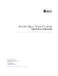
D397-12-880 Issue D Original
Instruction Manual
Turbo Controller
Description
Item Number
TIC Turbo Controller 100W
TIC Turbo Controller 200W
D397-11-000
D397-12-000
Turbo Controller
CONTENTS
PAGE
dcs/0121/0202
Section
Title
1
INTRODUCTION
1
1.1
1.2
Scope and definitions
Product description
1
1
2
TECHNICAL DATA
3
2.1
2.2
2.3
2.4
2.4.1
2.4.2
2.4.3
2.4.4
2.4.5
Electrical data
Operating and storage data
Mechanical data
Connections
Turbo pump connector
Backing pump connector
Auxiliary terminals
Logic interface
Serial communications
3
3
3
4
4
5
6
7
8
3
INSTALLATION
9
3.1
3.2
3.3
3.3.1
3.3.2
3.3.3
3.3.4
3.3.5
3.3.6
3.3.7
3.3.8
Unpack and inspect
Fitting the controller
Controller electrical connections
Connecting the electrical supply
Additional earth bonding
Connecting a turbo pump
Connecting a backing pump
Connecting a vent valve
Connecting an air cooler
Connecting the logic interface
Connecting the serial interface
9
9
12
12
12
13
13
13
13
14
16
4
OPERATION
19
4.1
4.2
4.3
4.4
4.5
4.6
4.7
4.8
4.8.1
4.8.2
4.8.3
4.9
4.10
4.11
4.12
4.13
4.14
4.15
Front panel description
Menu structure
Navigating the menu
The view screen
Turning pumps and relays ON/OFF
Changing list items
Changing numerical values
Pump set up
Introduction
Default pump set up options
Additional set up options using a DX pump
Alarms
The main menu
Pump status
Parameters/Units
Relay setpoint outputs
Service information
Electrical supply failure
19
20
22
22
23
23
23
24
24
24
26
27
27
27
28
28
29
29
Dec 05
i
Page
i
Issue D
Turbo Controller
CONTENTS (continued)
PAGE
ii
Section
Title
Page
5
MAINTENANCE
31
5.1
5.2
5.3
5.4
5.5
Safety
Fault finding
Cleaning the controller
Software updates
Factory defaults
31
31
31
32
32
6
STORAGE AND DISPOSAL
33
6.1
6.2
Storage
Disposal
33
33
7
SERVICE, SPARES AND ACCESSORIES
35
7.1
7.2
7.3
Service
Spares
Accessories
35
35
36
INDEX
39
RETURN OF BOC EDWARDS EQUIPMENT
Issue D
ii
Dec 05
Turbo Controller
CONTENTS (continued)
PAGE
iii
ILLUSTRATIONS
Figure
1
2
3
4
5
6
7
8
9
10
11
12
13
14
15
16
17
18
19
Title
Page
Pin connections for a 15-way sub-miniature ‘D’ type socket
Pin connections for a 15-way sub-miniature ‘D’ type socket
4-way screw terminal block
Pin connections for a 25-way sub-miniature ‘D’ type socket
Pin connections for a 9-way sub-miniature ‘D’ type socket
Bench mounted TIC dimensions (mm)
Front panel removal
Rack mounting of a TIC
Panel cut out drawing
Rear panel connections
IBM PC RS232 interface - 9-way
IBM PC RS232 interface - 25 way
RS485 TIC network
Front panel display
View screen shortcuts
Menu structure
Pump status
Changing numerical values
Pump set up screen
4
5
6
7
8
10
10
11
11
12
17
17
17
19
20
21
22
23
24
TABLES
Section
1
2
3
4
5
6
7
8
9
10
11
12
13
14
15
16
Dec 05
Title
Page
Compatible equipment for the TIC range
Turbo pump connector pin-out
Backing pump connector pin-out
Auxiliary connector pin-out
Logic interface connector pin-out
Serial communications connector pin-out
Checklist of components
Front panel symbols and their functions
Default pump setup options
Error/diagnostic monitoring, pumps
DX pump vent options
DX pump set up options
Error/diagnostic monitoring, DX pumps
Fault finding
Factory default settings
Accessories
iii
2
4
5
6
7
8
9
19
24
25
26
26
27
31
32
36
Issue D
Turbo Controller
PAGE
iv
This page intentionally blank.
Issue D
iv
Dec 05
Turbo Controller
1
INTRODUCTION
1.1
Scope and definitions
PAGE
1
Read this manual before you install and operate the BOC Edwards Turbo Controller. Important safety
information is highlighted as WARNING and CAUTION instructions; you must obey these instructions. The use
of WARNINGS and CAUTIONS is defined below.
WARNING
Warnings are given where failure to observe the instruction could result in injury or death to
people.
CAUTION
Cautions are given where failure to observe the instruction could result in damage to the equipment,
associated equipment and process.
Throughout this manual, page, figure or table numbers are sequential.
The following IEC warning label appears on the controller:
Warning - refer to accompanying documentation.
BOC Edwards offer European customers a recycling service.
1.2
Product description
WARNING
Improper use of the equipment could cause damage to it or injury to people. The user is
responsible for the safe operation and monitoring of the equipment. Hazardous voltages should
not be connected to this unit except where specified.
There are two variants of the Turbo Controller, both of which are provided with a large clear graphics display,
easy-to-use control interface via a touch sensitive keypad, an RS232/485 interface for control and data
monitoring on a remote PC and a logic interface for interface with associated system hardware.
Dec 05
1
Issue D
INTRODUCTION
This manual provides Installation, Operation and Maintenance instructions for the BOC Edwards Turbo
Controller. You must use the Controller as specified in this manual.
Turbo Controller
The compatible pumps/accessories that can be used with the Turbo Controller are listed in Table 1.
PAGE
TIC variant
2
Compatibility
INTRODUCTION
TIC Turbo Controller 100 W
EXT75DX - fast ramp
255DX - slow ramp
EXT70H + EXDC80 - fast ramp
EXT255H + EXDC80 - slow ramp
Mains backing pumps, XDS scroll, up to RV12 (via an optional
relay box)
Air Cooler, ACX70 and ACX250
Vent Valve, TAV5 and TAV6
Bakeout band (via an optional relay box)
24 V backing line valves, LCPV16EKA and LCPV25EKA (via an
optional relay box)
TIC Turbo Controller 200 W
Same as the 100 W version plus the following:
24 V backing pump
EXT255H + EXDC160 - fast ramp
255DX - fast ramp
Table 1 - Compatible equipment for the TIC range
Issue D
2
Dec 05
Turbo Controller
2
TECHNICAL DATA
2.1
Electrical data
PAGE
Fuse
Earth Stud
2.2
0 oC to 40 oC
-30 oC to 70 oC
Max 90% RH non condensing at 40 oC
3000 m max
20
Mechanical data
Weight
TIC Turbo Controller 100W
TIC Turbo Controller 200W
Dec 05
215 VA maximum (D397-11-000)
350 VA maximum (D397-12-000)
11 A at 110 V a.c. D397-11-000
23 A at 240 V a.c. D397-12-000
The unit is self-protecting and has no user replaceable
fuse. The unit will recover once any overload is removed.
M4
Operating and storage data
Ambient operating temperature range
Ambient storage temperature range
Maximum ambient operating humidity
Maximum operating altitude
IP rating
2.3
CEE/IEC 320
90 to 264 V a.c. 47 to 63 Hz
TECHNICAL DATA
Connector type
Electrical supply
Power consumption
TIC Turbo Controller 100W
TIC Turbo Controller 200W
Peak inrush current
3
1.8 kg
1.9 kg
3
Issue D
Turbo Controller
PAGE
4
2.4
Connections
2.4.1
Turbo pump connector
TECHNICAL DATA
Connector type
Power supply
Maximum output power
15-way sub-miniature ‘D’ type socket (refer to Figure 1)
24 V d.c.
100 W TIC: 80 W continuous, 120 W peak
200 W TIC: 160 W continuous, 240 W peak (combined total power of the
24 V turbo and backing pumps)
-0.5 V to 15 V
33 µA, 0 V to 13 V
active:
<1.1 V d.c. (Iout 20 mA max)
<0.8 V d.c. (Iout <2 mA)
inactive:
open (<24 V d.c. externally applied)
low:
<4.0 V d.c. (Iout<160 µA)
high:
7.0 V to 24 V d.c. (internally pulled up to 24 V)
disabled:
open
enabled:
0: > +8 V (Iout max: 8 mA)
1: < -8 V (Iout max: -8 mA)
mark:
<4.0 V d.c. (Iout < 160 µA)
space:
7.0 V to 24 V d.c. (internal pull up to 24 V)
Input voltage range
Output ID current
Control output
Control input
RS232 transmit
RS232 receive
Figure 1 - Pin connections for a 15-way sub-miniature ‘D’ type socket
Pin
1
2
3
4
5
6
7
8
9
10
11
12
13
14
15
Allocation
Power supply positive
Signal common
/Start signal output
RS232 Tx
/Serial enable output
Power supply positive
RS232 Rx
Power supply common
Speed signal input
Screen
Power supply positive
Screen
Power supply common
Power supply common
Normal signal input
Table 2 - Turbo pump connector pin-out
Issue D
4
Dec 05
Turbo Controller
2.4.2
Backing pump connector
Note:
Only applicable to the 200 W TIC
5
15-way sub-miniature ‘D’ type socket (refer to Figure 2)
24 V d.c.
160 W continuous, 240 W peak (combined total power of the 24 V turbo
and backing pumps)
Stop = 0 V
Start = 10 V (5 mA maximum)
33 µA, 0 V to 13 V
active:
<1.1 V d.c. (Iout < 20 mA)
<0.8 V d.c. (Iout < 2 mA)
inactive:
open (<24 V d.c. externally applied)
low:
<4.0 V d.c. (Iout<160 µA)
high:
7.0 to 24 V d.c. (internally pulled up to 24 V)
disabled:
open
enabled:
0: > +8 V (Iout max: 8 mA)
1: < -8 V (Iout max: -8 mA)
mark:
<4.0 V d.c. (Iout < 160 µA)
space:
7.0 V to 24 V d.c. (internal pull up to 24 V)
Output voltage range
Output ID current
Control output
Control input
RS232 transmit
RS232 receive
Figure 2 - Pin connections for a 15-way sub-miniature ‘D’ type socket
Pin
1
2
3
4
5
6
7
8
9
10
11
12
13
14
15
Allocation
Power supply positive
Signal common
/Start signal output
RS232 Tx
/Serial enable output
Power supply positive
RS232 Rx
Power supply common
Speed signal output
Screen
Power supply positive
Screen
Power supply common
Power supply common
Normal signal input
Table 3 - Backing pump connector pin-out
Dec 05
5
Issue D
TECHNICAL DATA
Connector type
Power supply
Maximum output power
PAGE
Turbo Controller
2.4.3
PAGE
6
Auxiliary terminals
TECHNICAL DATA
Connector type
Wire size
Power supply
Maximum output power
4-way screw terminal block (refer to Figure 3)
1.5 mm2 max
24 V d.c.
Fan:
3 W max
Vent-valve:
2 W max
active:
<1.5 V d.c.
inactive:
open
Control output
Figure 3 - 4-way screw terminal block
Pin
1
2
3
4
Allocation
Fan control output
Fan 24 V
Vent control output
Vent 24 V
Table 4 - Auxiliary connector pin-out
Issue D
6
Dec 05
Turbo Controller
2.4.4
Logic interface
PAGE
25-way sub-miniature ‘D’ type socket (refer to Figure 4)
24 V d.c.
5W
active:
<1.1 V d.c. (Iout < 20 mA)
<0.8 V d.c. (Iout < 2 mA)
inactive:
open (internal pull up to 24 V)
low:
<2.0 V d.c. (Iout<160 µA)
high:
3.5 V to 24 V d.c. (internal pull up to 24 V)
0 to 10 V (5 mA max)
50 mV resolution
Control input
Analogue output
7
TECHNICAL DATA
Connector type
Power supply
Maximum output power
Control output
Figure 4 - Pin connections for a 25-way sub-miniature ‘D’ type socket
Pin
1
2
3
4
5
6
7
8
9
10
11
12
13
14
15
16
17
18
19
20
21
22
23
24
25
Allocation
Screen
Analogue output signal
Setpoint 1 output
Vent control output
Bakeout band control output
N/C
Power supply common
Backing pump control output
N/C
Power supply common
Power supply positive
Power supply common
Power supply common
Analogue output common
Setpoint 2 output
Setpoint 3 output
Turbo normal output
Alarm output
Air cooler output
N/C
N/C
Backing pump enable input
Turbo stand-by control input
Turbo pump enable input
System interlock input (SYSI)
Table 5 - Logic interface connector pin-out
Dec 05
7
Issue D
Turbo Controller
2.4.5
PAGE
8
Serial communications
Connector type
RS232 transmit
TECHNICAL DATA
9-way sub-miniature ‘D’ type socket (refer to Figure 5)
mark:
< - 8 V (Iout max: -8 mA)
space:
> +8 V (Iout max: -8 mA)
mark:
< +1.0 V (Iin max: -2.0 mA)
space:
>+2.0 V (Iin max: +2.0 mA)
maximum input: ±12 V
9600 baud, 1 stop bit, 8 data bits, no parity, Xon/Xoff
Output differential:
>1.5 V (Iout max: ± 25 mA)
Input differential threshold:
>± 0.2 V (Iin max: ± 1 mA)
Maximum input:
-7.0 V to +12 V
The TIC applies one unit load to the RS485 bus.
RS232 receive
RS232 protocol
RS485
Bus load
Figure 5 - Pin connections for a 9-way sub-miniature ‘D’ type socket
Pin
1
2
3
4
5
6
7
8
9
Allocation
N/C
RS232 transmit
RS232 receive
N/C
RS232 common
N/C
N/C
RS485 data A
RS485 data B
Table 6 - Serial communications connector pin-out
Issue D
8
Dec 05
Turbo Controller
3
INSTALLATION
3.1
Unpack and inspect
PAGE
9
Check that your package contains the items that are listed in Table 7. If any of these items are missing, notify
your supplier in writing within three days. If the Controller is not to be used immediately, store the Controller
in suitable conditions as described in Section 6.1.
Quantity
Description
Check()
1
Controller
R
1
Quick Guide and Health and Safety Information
R
1
TIC CD
R
2
Rear non-slip feet
R
1
Logic interface plug
R
Table 7 - Checklist of components
3.2
Fitting the controller
WARNING
If access to the IEC connector is restricted an additional isolation device should be provided,
which will be easily accessible by an operator.
CAUTION
Rubber feet must be fitted (Figure 6, item 1) so that there are correct clearances for air circulation. If you do
not, the performance of the Controller may be affected at high operating temperatures.
The Controller can be used on a bench-top or can be fitted in a rack or cabinet. Figure 6 shows the dimensions
of the TIC that are required for bench top use.
Note:
Dec 05
If the interlocks are not used the logic interface adaptor must be fitted to the 25-way connector.
9
Issue D
INSTALLATION
Remove all of the packaging material and check the Controller. If the Controller is damaged, follow the BOC
Edwards return of equipment procedures that are laid out in the back of this manual. Do not use the Controller
if it is damaged.
Turbo Controller
PAGE
10
INSTALLATION
1. Rubber foot
Figure 6 - Bench mounted TIC dimensions (mm)
WARNING
Ensure that all electrical wiring is safely secured so that people cannot trip on them.
If a Controller is fitted in a rack, cabinet or panel, follow the directions given in Figures 7, 8 and 9.
CAUTION
Allow 150 mm at the rear for cables. Allow 50 mm top and bottom and 15 mm to the sides for sufficient air
circulation. Do not cover any of the ventilation holes.
CAUTION
This unit is IP20 rated. Please ensure that the unit is not installed where fluids can enter into the controller.
CAUTION
The unit must be supported at the rear.
1. Bench top adaptor
2. Fixing screw and washer
Figure 7 - Front panel removal
Issue D
10
Dec 05
Turbo Controller
• Remove the bench top adaptor (Figure 7, item 1) by removing the four screws (Figure 7, item 2).
• Slide the Controller into the 19" rack or panel cut out. The use of 19" rack guide rails (Figure 8, item 2)
and support at the rear of the Controller is recommended as shown in Figure 8. The panel cut out
information is defined in Figure 9.
1. Fixing screw and washer
2. 19" rack guide rails
Figure 8 - Rack mounting of a TIC
Figure 9 - Panel cut out drawing
Dec 05
11
11
INSTALLATION
• Fix the Controller in place using the four screws removed previously (Figure 8, item 1).
PAGE
Issue D
Turbo Controller
3.3
Controller electrical connections
PAGE
12
INSTALLATION
1.
2.
3.
4.
5.
6.
7.
8.
Backing pump (200 W only)
Turbo pump connection
Logic interface
Serial communications port
Earth stud
Mains input
Mains on/off
Auxiliary terminals
Figure 10 - Rear panel connections
3.3.1
Connecting the electrical supply
WARNING
High voltages exist in the Controller when it is operating. Ensure that the Controller is earthed
and observe all appropriate safety precautions for the safe installation and handling of electrical
equipment. If you do not, there will be a danger of injury or death to people by electric shock.
Ensure that the electrical supply switch is set to ‘off’ and then connect the Controller to the electrical supply
with an appropriate supply cable.
3.3.2
Additional earth bonding
The electrical supply cable normally provides protective earthing for electrical safety. If this is not the case, or
if additional earth bonding is required, then the earth stud on the rear of the Controller (Figure 10, item 5)
should be connected to your vacuum system earth.
The earth connection of any vent valves or air coolers should also be connected to this earth stud to ensure
that they are adequately earthed.
Connect a suitably earthed cable between the two nuts fitted to the earth stud on the rear of the TIC.
Note:
Issue D
Do not remove the bottom nut from the earth stud.
12
Dec 05
Turbo Controller
3.3.3
Connecting a turbo pump
PAGE
A suitable turbo pump can be connected to the TIC turbo pump connector on the rear panel.
13
3.3.4
Connecting a backing pump
Both the 100 W and 200 W TICs can control a mains backing pump via the logic interface. For details of this,
refer to Section 3.3.7.3.
The 200 W TIC can also drive a suitable backing pump from it’s second rear panel pump connector.
Connect the pump to the upper of the two 15 way ‘D’ connectors and tighten the locking screws to ensure the
connector cannot come loose.
Note:
To control an XDD1 24 V backing pump, the pump must be configured for ‘analogue speed control’. Please
refer to the pump instruction manual for details on how to configure the pump for this operating mode.
3.3.5
Connecting a vent valve
A vent valve can be driven from either the auxiliary terminals on the rear of the TIC, or from the logic interface.
For details of using the logic interface to control a vent valve, see Section 3.3.7.3.
Note:
If a DX pump is to be used, it is recommended that the vent valve is connected to the pump, not the TIC
Controller. If two vent valves are required, both the DX and TIC vent outputs can be used at the same time.
(Refer to Table 11).
Connect the positive lead of the vent valve to the terminal marked ‘Vent +’, connect the negative lead of the
vent valve to the terminal marked ‘Vent –’, and clamp the earth wire between the earth stud locking nuts on the
rear of the controller. Ensure the screws and the earth terminal locking nut, are all firmly tightened.
3.3.6
Connecting an air cooler
An air cooler can be driven from either the auxiliary terminals on the rear of the TIC, or from the logic interface.
For details of using the logic interface to control an air cooler, refer to Section 3.3.7.3.
Connect the positive lead of the air cooler to the terminal marked ‘Fan +’, connect the negative lead of the air
cooler to the terminal marked ‘Fan –’, and clamp the earth wire between the earth stud locking nuts on the rear
of the controller. Ensure the screws and the earth terminal locking nut, are all firmly tightened.
Dec 05
13
Issue D
INSTALLATION
Connect the pump to the lower of the two 15 way ‘D’ connectors and tighten the locking screws to ensure the
connector cannot come loose.
Turbo Controller
3.3.7
PAGE
Connecting the logic interface
3.3.7.1 Introduction
14
Note:
INSTALLATION
In most applications it will be preferable not to earth the logic interface power supply common to prevent earth
loops inadvertently occurring.
CAUTION
Do not connect voltages greater than 24 V to the logic interface.
The logic interface provides a number of signals that can be used for monitoring the status of your vacuum
system, and for controlling certain aspects of its operation. These signals can be broadly divided into three
groups, control inputs, control outputs and status outputs.
3.3.7.2 Using control inputs
Control inputs provide a means of controlling the operation of the TIC and the associated vacuum system from
external sources.
Turbo Stand-by: To cause the turbo pump to run at stand-by speed, link ‘Turbo Stand-by’ to 0 V. To return the
pump to full speed, disconnect ‘Turbo Stand-by’ from 0 V. Note only pumps that have stand-by speed capability
will respond to this input.
Turbo Enable: The turbo enable input can be used to control the operation of the turbo pump. If turbo enable
is open, the turbo pump cannot be started, and will stop if it is running. If turbo enable is connected to 0 V when
power is applied to the TIC, the pump is able to start when commanded to do so. If turbo enable is connected
to 0 V while the controller is operating, the turbo pump will start, as long as SYSI and the software configuration
allow it to do so.
Backing Pump Enable: The backing pump enable input can be used to control the operation of the backing pump.
If backing pump enable is open, the backing pump cannot start, and will stop if it is running. If backing pump enable
is connected to 0 V when power is applied to the TIC, the pump is able to start when commanded to do so. If
backing pump enable is connected to 0 V while the controller is operating, the backing pump will start, as long
as ‘SYSI’ and the software configuration allow it to do so.
SYSI: The System interlock input can be used to interlock the TIC to a system fail or control signal. When ‘SYSI’
is open, all pumps will stop and the vent valve will be opened. The TIC will also trip into the fail condition. To
clear the system interlock and allow the pumps and gauges to start, connect ‘SYSI’ to 0 V.
WARNING
’SYSI’ is not fail safe and should not be relied upon for safety critical applications.
Issue D
14
Dec 05
Turbo Controller
3.3.7.3 Using control outputs
CAUTION
The vent valve output on the logic interface will not be maintained in the event of a power failure. If venting
of your turbo pump while it is running at high speed is undesirable, use the vent valve output from the auxiliary
terminals. This output will be maintained during a power failure.
Bakeout band control: The bakeout band control can be used to switch a relay that can apply power to the band.
The relay box has a relay built in for this purpose and provides connectors to allow power to be applied to the
bakeout band. Refer to the relay box instruction manual for further information on driving a bakeout band.
To drive a relay without a relay box, connect the coil of a suitable 24 V d.c. relay between ‘Bakeout Band Control
Output’ (negative) and ‘Power Supply Positive’ (positive).
Backing pump control: The backing pump control can be used to switch a relay that can apply power to a mains
backing pump. The relay box has a relay built in for this purpose and provides a connector that will switch the
pump on and off. Refer to the relay box instructions for further information on driving a backing pump.
To drive a relay without a relay box, connect the coil of a suitable 24 V d.c. relay between ‘Backing Pump Output’
(negative) and ‘Power Supply Positive’ (positive).
Air cooler: The air cooler output can be used to control the operation of an air cooler. The air cooler signal
will be driven low to energise the cooler when required. Connect the positive lead of the cooler to the power
supply positive and the negative lead to ‘Air Cooler Control’. The air cooler earth lead must be connected to
‘Screen’ or a suitable alternative earth point.
3.3.7.4 Using status outputs
Status outputs provide a means for external systems to react based upon the current state of the TIC.
Analogue output: The analogue output provides a 0 V to 10 V signal that can be configured to represent system
pressure, pump speed etc. Refer to Section 4.8 for how to configure this output.
To connect this output to an external system, connect the ‘Analogue Output Signal’ to the positive input of your
system and ‘Analogue Output Common’ to the negative side.
Relay setpoint: The setpoint outputs can be used to interface to external logic or can be used to drive relays.
Each output can be configured in software to activate at pump speed. Refer to Section 4.13 of the main manual
for how to configure these outputs. Each relay can be manually controlled. Refer to Section 4.5.
The relay box has built in relays that can switch external loads and provides a connector to interface to an
external system. Refer to the relay box instructions for further information on using the setpoint outputs.
Dec 05
15
Issue D
PAGE
15
INSTALLATION
Control outputs provide a means for the TIC to control external resources.Vent valve control: The vent valve
output can be used to control the operation of a vent valve. The ‘Vent Valve’ signal will be driven low to energise
the valve when required. Connect the positive lead of the vent valve to ‘24 V’ and the negative lead to ‘Vent
Valve Control’. The vent valve earth lead must be connected to ‘Screen’ or a suitable alternative earth point.
Turbo Controller
To drive a relay without a relay box, connect the coil of a suitable 24 V d.c. relay between ‘Setpoint Output’
(negative) and ‘Power Supply Positive’ (positive).
PAGE
16
INSTALLATION
Turbo normal speed: Turbo normal speed can be used to interface to external logic or can be used to drive a
relay. This output is normally inactive and will become active when the turbo pump has reached its defined
‘Normal’ speed.
To drive a relay, connect the coil of a suitable 24 V d.c. relay between ‘Turbo Normal Output’ (negative) and
‘Power Supply Positive’ (positive).
Alarm: Alarm can be used to interface to external logic or can be used to drive a relay. This output is normally
active and will become inactive in the event of an alarm condition.
To drive a relay, connect the coil of a suitable 24 V d.c. relay between ‘Alarm Output’ (negative) and ‘Power
Supply Positive’ (positive).
3.3.8
Connecting the serial interface
The TIC has two serial communications protocols built in, RS232 and RS485. RS232 is the simplest interface and
can be used to allow a host PC to control the TIC. RS485 allows a host PC to control a small network of TICs.
3.3.8.1 Connecting RS232
The TIC is fitted with a 9-way ‘D’ type socket on the rear panel. The interface uses two lines for data transfers
and an additional line as a signal common. Hardware handshaking is not implemented.
If connecting to an IBM compatible PC fitted with a 9-way ‘D’ type socket then a ‘straight through’ male-female
9-way extension cable can be used to connect the TIC to the computer as shown in Figure 11. Connection to
an IBM PC fitted with a 25-way serial connector should be made as shown in Figure 12.
Use shielded cable for the interface to reduce interference problems and limit the length of the RS232 link to
less than 10 metres. For longer links, either install line drivers or use RS485.
Issue D
16
Dec 05
Turbo Controller
PAGE
17
INSTALLATION
Figure 11 - IBM PC RS232 interface - 9-way
Figure 12 - IBM PC RS232 interface - 25 way
3.3.8.2 Connecting RS485
RS485 provides the TIC with the capability to be networked with other TICs and a host PC as shown in
Figure 13.
CAUTION
All of the ground connections are tied together. If differences exist in the local ground voltage, damage could
occur. If the TICs being networked are liable to experience different ground potentials, a suitable RS485
isolator should be connected between them.
Use shielded cable for the interface to reduce interference problems and limit the length of the RS485 link to
less than 1000 metres.
Long links may require the addition of 120 Ω terminating resistors at each end of the link to improve
communications reliability.
Figure 13 - RS485 TIC network
Dec 05
17
Issue D
Turbo Controller
PAGE
18
This page intentionally blank.
Issue D
18
Dec 05
Turbo Controller
4
OPERATION
4.1
Front panel description
PAGE
19
OPERATION
Figure 14 - Front panel display
Symbol
Name
UP
DOWN
SELECT
MENU
CYCLE
Function
Move up through a menu.
Cycle selected numerical values up.
Cycle a selected list item upwards.
Move down through a menu.
Cycle selected numerical values down.
Cycle a selected list item downwards.
Enter the highlighted sub-menu.
Edit the highlighted list or numerical item.
Move to the next digit of a numerical value.
Jump to the setup screen for the highlighted pump.
Switch between the default view screen and the main menu.
Exit the current sub-menu or setup screen.
Abort edit of a selected list item.
Move to the previous digit of a numerical value.
Turn a highlighted pump on or off.
Table 8 - Front panel symbols and their functions
Dec 05
19
Issue D
Turbo Controller
4.2
PAGE
20
Menu structure
Figures 15 and 16 show the view screen shortcuts and menu structure for the TIC. They also give an indication
as to what buttons will take you where within the menu layout.
OPERATION
Figure 15 - View screen shortcuts
Issue D
20
Dec 05
Turbo Controller
PAGE
21
OPERATION
Figure 16 - Menu structure
Dec 05
21
Issue D
Turbo Controller
4.3
PAGE
22
Navigating the menu
This section summarises the display navigation method for the TIC. There are 4 buttons for menu navigation
and configuration tasks. A fifth button is used for switching pumps ON and OFF. In most configuration tasks
there are no more than three menu levels.
OPERATION
Refer to Table 8 for a description of the functions that the buttons on the front panel perform.
4.4
The view screen
The view screen can be set to various view options. The following, describes the view screen that shows ‘all’.
(Refer to Figure 17).
The top portion of the view screen shows the status of the vacuum pumps; the top line shows the pump speed
as a bar chart. In the top right-hand corner the status of the turbo pump is shown as follows:
Off.
>>>.
<<<.
Run.
Norm.
Strt.
Flt.
The turbo pump is off.
The turbo pump is accelerating.
The turbo pump is decelerating.
The turbo pump is above 50% speed.
The turbo pump is at or above
‘normal speed’.
The turbo pump is enabled to start,
but will not run until the start delay
has run down.
An error has occurred. Select the
alarms screen.
The second line provides the basic status of the turbo pump and backing pump under TIC command.
The status of the setpoint relays is shown at the bottom line of the view screen. Relays that are on are shown
in reverse video.
Figure 17 - Pump status
Issue D
22
Dec 05
Turbo Controller
4.5
Turning pumps and relays ON/OFF
Pressing the ‘Cycle’ (
will appear.
If SYSI is opened during the vacuum cycle, all connected controllable components will be switched OFF.
If the selected item is the relay status line, a list of the relays will appear. Scroll to the required relay, use the
’cycle’ (
) button to switch the item. When the relay is activated the annunciator on the view screen will
change to reverse video.
4.6
Changing list items
To change a list item, scroll to the required line and press the ‘Select’ (
using the up and down arrows ( / ).
) button. The list can then be scrolled
Pressing the ‘Select’ ( ) button will accept the adjustment and return the highlight to the row item, allowing
another item to be selected for adjustment.
Pressing the ‘Menu’ (
) button will cancel the adjustment and return the highlight to the row item, allowing
another item to be selected for adjustment.
4.7
Changing numerical values
To change a numerical item, scroll to the required line and press the ‘Select’ ( ) button. The first number will
then be highlighted and can be changed using the up and down arrows ( / ).
The ‘Select’ ( ) button will move the highlight to the next digit with each successive press, allowing the
complete number to be entered. Pressing the ‘Select’ ( ) button with the last digit selected will accept the
adjustment and return the highlight to the row item, allowing another item to be selected for adjustment.
At any time, mistakes can be corrected by pressing the ‘Menu’ (
) button. This will move the highlight to the
previous digit with each successive button press, allowing corrections to be made. Pressing the ‘Menu’ (
)
button with the first digit selected will cancel the adjustment and return the highlight to the row item, allowing
another item to be selected for adjustment.
Figure 18 - Changing numerical values
Dec 05
23
Issue D
PAGE
23
OPERATION
Note:
) button whilst the turbo/backing status line is highlighted, a menu of switchable items
Turbo Controller
PAGE
24
4.8
Pump set up
4.8.1
Introduction
OPERATION
The TIC can be used to configure the EXT and DX pump ranges. The menu screen shows differing functionality
depending on the pump attached. The TIC will recognise the pump attached, which will be seen on the pump
set up and pump status screen. (Refer to Figure 19).
Figure 19 - Pump set up screen
4.8.2
Default pump set up options
Menu option
Description
Ramp Up Timer
The user can set the ramp up timer from 1 to 8 minutes. This timer will generate an
alarm if the pump speed does not rise above 50% speed after the set time.
Droop Timer
The user can set the droop time from 1 to 8 minutes. This timer will generate an
alarm if the pump speed drops below 50% speed for longer than the specified time.
Heater time
The user can set the time that the heater band bakes out the turbo pump from 0 to
35 hrs. The heater will come on for the set time, once the pump reaches 'normal
speed'. If the pump drops below 'normal speed', the heater band will switch off and
the timer will be reset.
Start delay
The start delay enables the user to delay the start of the turbo pump from 0 to 99
minutes.
System ON
Allows the user to define the components of the system that are to be turned on,
when the 'system' is cycled on.
System OFF
Allows the user to define the components of the system that are to be turned off,
when the 'system' is cycled off.
Note:
The system ON and OFF commands provide manual control of the items listed.
Where possible it will override settings such as backing options and gauge linking.
Note:
If the backing pump option has been set to 50% or on stop, ’seq’ will be indicated
showing the backing pump is sequenced to one of the options.
Table 9 - Default pump setup options
Issue D
24
Dec 05
Turbo Controller
Menu option
Air cooler
Backing pump options
The user can set when a BOC Edwards air cooler should operate. The air cooler
can be set to 'ON' (on permanently) or 'Turbo' (on when the turbo pump is
running).
A vent valve attached to the TIC can be operated in the following ways:
'On stop' to open the vent valve 2 seconds after the stop command, or '50%' to
open the vent valve when the pump slows to 50% speed.
A backing pump attached to the TIC or via a relay box can be operated in the
following way:
None:
The backing pump is not sequenced to the Turbo pump
50%:
The backing pump will turn off after 2 seconds, once the turbo speed has
dropped to 50% of its speed. The delay allows detritus to be removed
from the system on stop.
On stop: The backing pump will turn off 4 seconds after the Turbo off command
has been sent. The 4 second delay allows shutting of a valve and then
removal of detritus from the system.
Table 9 - Default pump setup options
Please refer to Table 10 for error and diagnostic information for pumps.
CAUTION
If an Edwards 24 V backing pump is connected, it is advised that the overall power used does not exceed the
data specified in Section 2.
Diagnostic messages Description
RampUp Timeout
Check whether the pump is too hot or whether the inlet pressure is too high.
Check that the backing pump is operational.
Check your vacuum system for leaks.
Droop Timeout
Check whether the pump is too hot or whether the inlet pressure is too high.
Check that the backing pump is operational.
Check your vacuum system for leaks.
Table 10 - Error/diagnostic monitoring, pumps
Dec 05
25
Issue D
PAGE
25
OPERATION
TIC vent options
Description
Turbo Controller
4.8.3
PAGE
26
Additional set up options using a DX pump
The TIC allows the user to set up additional functionality available within a DX pump.
CAUTION
OPERATION
Read the DX pump manual before using the TIC to set up the DX pump.
DX vent options - If a DX pump is attached, the user can set up one of the DX vent options. The user can set
up the DX vent, and also the TIC vent to enable two vent valves to be connected to a vacuum system. (Refer
to Table 11).
On screen
50%
Description of DX vent function
Vent valve opens fully below 50% full rotational speed for both Stop command or Fail
Note: This is the default factory setting.
50%CvV
Controlled venting from 100% - 50% full rotational speed;
Vent valve opens fully below 50% for both Stop command or Fail
STP50%
Vent valve opens fully immediately Stop command is received;
Vent valve opens fully below 50% full rotational speed if Fail
STPCnV
Vent valve opens fully immediately Stop command is received;
Controlled venting from 100% - 50% full rotational speed then vent valve opens fully below
50% if Fail
FLT50%
Vent valve opens fully immediately if Fail;
Vent valve opens fully below 50% full rotational speed if Stop
FLTCnV
Vent valve opens fully immediately if Fail;
Controlled venting from 100% - 50% full rotational speed then vent valve opens fully below
50% if Stop command received
STPFLT
Vent valve opens fully immediately for both Stop command or Fail
FLTSTP
Vent valve opens fully immediately for both Stop command or Fail
FAN
Vent is Permanently Enabled, and can be used to provide power to a BOC Edwards air
cooler
Table 11 - DX pump vent options
Menu option
Normal
Standby speed
Max power
Braking
Description
The TIC allows ‘normal speed’ to be set as a percentage of full speed.
The user can set the standby speed as a percentage of full speed.
The user can set the maximum power a DX pump can use.
Off/Enabled. The user can utilise this function to slow the turbo pump at a quicker
rate.
Table 12 - DX pump set up options
Issue D
26
Dec 05
Turbo Controller
Please refer to Table 13 for the error and diagnostic information for DX pumps
PAGE
.
Diagnostic messages Description
Serial ID Fail
SC Interlock
Uload Timeout
Dload Failed
A DX or serial pump is connected, however the type has not been recognised.
Please check the leads are connected.
Review the flashing error codes on the pump podule, and refer to the DX
instruction manual.
Serial enable to the DX pump was lost while it was running. This could be caused
by a temporary loss of power or a broken wire. It is recommended to stop the
pump and then restart it. If the alarm does not clear, cycle the controller and then
try again.
Check that the pump is correctly connected, then try to upload again.
Check that the pump is correctly connected, then try to download again.
Table 13 - Error/diagnostic monitoring, DX pumps
4.9
Alarms
If an Alarm occurs, an ‘Alarms’ warning will begin flashing in the lower half of the view screen. Refer to Figure 17.
The Alarm can then be selected by moving the cursor over it and pressing the ‘Select’ ( ) button. This action
will take you to the Alarms screen. Alternatively the Alarms screen can be accessed through the main menu.
The Alarm will stop flashing when it has been acknowledged and will disappear when the alarm situation no
longer exists. An alarm is acknowledged by pressing the ‘Select’ ( ) button whilst the flashing alarm is
highlighted.
To clear an alarm you will need to refer to the fault finding guide in Section 5 of this instruction manual. This
guide gives information of what the alarm is and the possible solutions for clearing the alarm.
4.10
The main menu
The main menu can be accessed by pressing the ‘Menu’ (
From here the following sub-menus can be accessed.
4.11
) button on the view screen (refer to Figure 14).
Pump status
This screen allows the user to view the current status of the Turbo and Backing pumps. Basic information such
as:
• Whether the Turbo pump is ON or OFF.
• The state of the turbo pump that the user has requested.
• Whether the Backing pump is ON or OFF.
• The power that the Turbo pump is using.
• The speed of the Turbo pump as a percentage of full speed.
Dec 05
27
Issue D
OPERATION
DX Fault
27
Turbo Controller
• The temperature of the power supply.
PAGE
28
• The temperature of the Turbo drive. (Only on DX pumps).
• The temperature of the Turbo pump. (Only on DX pumps).
OPERATION
• The cycle time is the run time of the current cycle. (Only on DX pumps).
• Where the vent valve is ‘on/off’.
4.12
Parameters/Units
This screen allows the user to change the units that are displayed and other parameters such as:
• Setup lock - When the 3 digit lock code is entered, the lock is enabled and an operator will not be able
to change any of the setups, however the operator is still able to scroll through the menus and start and
stop pumps. The lock is disabled by entering the 3 digit unlock code again.
• Panel Lock - This function completely locks the front panel. An operator will only be able to see the view
screen. The password for this function is shown on the CD inlay card.
• The 0 - 10 V analogue output on the logic interface can be set to follow the turbo speed.
• Display contrast allows the user to change the contrast of the display.
• Protocol shows whether RS232 or RS485 is being used.
• Comms address - To set the comms address of the TIC.
4.13
Relay setpoint outputs
The relay setpoints option allows the setpoint outputs on the logic interface to be linked to turbo speed. When
selected, a summary of the current setting is displayed. The default setting for the three relays is ‘Not Linked’.
There are four steps to set up the links, proceed as follows:
Select the controlled relay. Scroll to the relay that is to be controlled and press the ‘Select’ (
) button.
Select the controlling item. The top highlighted line is used to select the controlling item. The controlling item
can either be ‘Not Linked’ or ‘Turbo Speed’ (%). Press the ‘Select’ ( ) button to confirm the choice.
Enter the required setpoint. The ‘On’ and ‘Off’ setpoints can be adjusted to suit the application. For pumps, the
unit used is ‘Turbo Speed’ (%).
Note:
For pumps, the ‘Off’ setpoint is less than or equal to the ‘On’ setpoint.
Enable the set point. Once configured, the setpoint should be enabled by changing the bottom ‘Setpoint’ line
from ‘OFF’ to ‘ENABLED’.
Issue D
28
Dec 05
Turbo Controller
4.14
Service information
PAGE
Service information contains the following information:
29
• Serial Number - The serial number of the TIC is used when contacting BOC Edwards about the product.
• Analogue O/P - The analogue output value (internal units) is used when contacting BOC Edwards about
the product.
• Turbo run - Number of hours the turbo pump has been run (DX pumps only).
• Reset DX - Reset the DX turbo pump to it’s factory defaults (DX pumps only).
• Reset TIC - Resets the TIC to it’s factory default configuration and can be used to quickly undo all user
settings (relay setpoints, units, etc.).
• Upload DX - The TIC can store one set of the DX pump’s configuration. This function will upload the
current configuration from the attached DX pump (DX pump only).
• Download DX - The TIC can download one set of DX configurations to DX pumps, once a configuration
has been uploaded. This function will download the stored configuration to the attached DX pump
(DX pump only).
4.15
Electrical supply failure
If the electrical supply to the controller fails while the turbo pump is rotating at high speed, the pump begins
acting like a generator and will supply power back to the TIC. This power will be used to maintain operation of
the vent valve, and if enough power is available the TIC will maintain operation.
The power returned to the TIC is not made available to the logic interface or the air cooler; all of these will
stop operating until power is restored.
Once the turbo pump speed falls below 50%, the vent valve will open and the TIC will shut down.
Dec 05
29
Issue D
OPERATION
• Software Issue - This is the issue of the currently installed software. This will change when new software
is downloaded to the TIC in the future.
Turbo Controller
PAGE
30
This page intentionally blank.
Issue D
30
Dec 05
Turbo Controller
5
MAINTENANCE
5.1
Safety
PAGE
31
Obey the safety instructions given below and take note of the appropriate precautions. If you do
not, you could cause injury to people or damage to equipment.
There are no serviceable parts on the TIC. Do not open, return to your nearest BOC Edwards service centre
for any repairs that are necessary.
The BOC Edwards return of equipment forms can be found at the rear of this manual.
5.2
Fault finding
General
DX
Pump
Diagnostic messages
Description
RampUp Timeout
Refer to Table 10.
Droop Timeout
Refer to Table 10.
Serial ID Fail
Refer to Table 13.
DX Fault
Refer to Table 13.
SC Interlock
Refer to Table 13.
Uload Timeout
Refer to Table 13.
Dload Failed
Refer to Table 13.
SYSI Inhibit
The system interlock has been disconnected. Please check that the logic
interface plug is connected correctly, or check the status of the system
interlocks.
Ext Inhibit
Enable lines have been disconnected, please check the Turbo or Backing
pump enable lines.
No Reading
An object has not received a value update from its source within a given
time and is flagging that its value is now old. Check connections to
components of system.
No Message
An object has not received a reply to a message it sent within a given time.
Check logic interface connections, are correctly attached to the TIC.
Table 14 - Fault finding
5.3
Cleaning the controller
If necessary, use a soft dry cloth to clean the exterior of the Controller. Do not clean with harsh abrasives or
liquids.
If the interior of the Controller requires cleaning, it is our recommendation that you return the Controller to
your supplier or your nearest BOC Edwards Service Centre.
Dec 05
31
Issue D
MAINTENANCE
WARNING
Turbo Controller
5.4
PAGE
32
Software updates
The software within the Controller and the TIC PC monitor program will be updated as part of BOC Edwards
ongoing development program. The updates and associated instruction manual can be found by visiting
www.upgrades.bocedwards.com.
MAINTENANCE
5.5
Factory defaults
The following is a list of factory default settings for the TIC:
Menu option
Default
Pump and relay slaving
- not slaved
Turbo pump start delay
=0
EXDC Ramp time
=8
EXDC Droop time
=8
Analogue out slaved
= NONE
TIC vent
= 50%
Heater band
= 0 hrs
Air Cooler
= Turbo
Setup lock
= Off
Panel lock
= Off
Display contrast
PC comms
Multi-drop address
Default screen
=5
= RS232
=0
= All
System On
= Backing
System Off
= Turbo
Backing option
= None
Table 15 - Factory default settings
Issue D
32
Dec 05
Turbo Controller
6
STORAGE AND DISPOSAL
6.1
Storage
PAGE
33
6.2
Disposal
Dispose of the Controller and any components safely in accordance with all-local and national safety and
environmental requirements.
Alternatively, you may be able to recycle the Controller and/or cables; contact BOC Edwards or your supplier
for advice (also see below).
The Controller and associated cables are within the scope of the European Directive on Waste Electrical and
Electronic Equipment, 2002/96/EC. BOC Edwards offer European customers a recycling service for the
Controller/cables at the end of the product’s life. Contact BOC Edwards for advice on how to return the
Controller/cables for recycling.
WARNING
Do not incinerate the Controller. If the Controller is heated to very high temperatures,
dangerous gases may be emitted and internal components may explode.
Dec 05
33
Issue D
STORAGE AND DISPOSAL
Store the Controller in clean dry conditions in accordance with the technical specifications. Refer to Section 6
of the main manual on CD.
Turbo Controller
PAGE
34
This page intentionally blank.
Issue D
34
Dec 05
Turbo Controller
7
SERVICE, SPARES AND ACCESSORIES
7.1
Service
PAGE
35
For more information about service options, contact your nearest Service Centre or other BOC Edwards
company.
7.2
Spares
Spare
Item Number
TIC Front Bezel Kit
TIC Logic Interface
Front Panel Assembly
D397-00-803
D397-00-850
D397-00-822
Note:
Dec 05
This assembly is suitable for customers who have electrical and electronic repair expertise and possess a
portable appliance tester. If the customer is unable to carry out this repair, the Controller should be returned
to BOC Edwards for a full repair and safety re-test.
35
Issue D
SERVICE, SPARES AND ACCESSORIES
A worldwide network of BOC Edwards Service Centres supports BOC Edward’s products. Each Service Centre
offers a wide range of options including equipment decontamination; service exchange; repair; rebuild and testing
to factory specifications. Equipment, which has been serviced, repaired or rebuilt, is returned with a full
warranty.
Turbo Controller
7.3
PAGE
36
Accessories
Table 16 shows the range of accessories that can be purchased.
SERVICE, SPARES AND ACCESSORIES
Product Description
TIC Controllers
TIC Profibus Module
Turbo Pumps and Controllers
EXT70H range
(EXDC80 Control Module required with above Turbo Pumps)
EXT255H range
(EXDC160 Control Module required with above Turbo Pumps)
EXT75DX range
EXT255DX range
Extension Cables DX/EXDC and 24V backing pumps
1m DX/EXDC extension cable (16/0.2)
3m DX/EXDC extension cable (16/0.2)
5m DX/EXDC extension cable (16/0.2)
Air Cooler
ACX70
ACX250
Vent Valves
TAV5
TAV6
Examples of compatible 24 V backing pumps
XDD1 24 V d.c. Diaphragm pump
Examples of compatible mains backing pumps
XDS10 220-240 V 50 Hz 1-phase
XDS10 115-120 V 60 Hz 1-phase
E2M1.5 220-240 V 50/60 Hz 1-phase
E2M1.5 115-120 V 50/60 Hz 1-phase
RV12 110-120 V 60 Hz or 220-240 V 50 Hz 1-phase
E2M28 220-240 V 50 Hz or 230-240 V 60 Hz 1-phase
E2M28 115/230 V 60 Hz 1-phase
Bakeout band (via optional relay box)
BX70 240 V 30 W (EXT70H & EXT75DX)
BX70 110 V 30 W (EXT70H & EXT75DX)
BX250 240 V 60 W (EXT255H)
BX250 110 V 60 W (EXT255H)
24 V backing line valves (via optional relay box)
LCPV16EKA 24 V a.c./d.c.
LCPV25EKA 24 V a.c./d.c.
Ordering Information
D397-50-000
D396-45-000
D396-46-000
D397-00-835
D397-00-836
D397-00-837
B580-53-050
B580-53-150
B580-66-010
B580-66-020
A746-01-991
A726-01-903
A726-01-906
A371-22-919
A371-22-902
A655-01-903
A373-15-903
A373-15-981
B580-52-060
B580-52-040
B580-52-061
B580-52-041
C417-51-200
C417-52-200
Table 16 - Accessories
Issue D
36
Dec 05
Turbo Controller
Ordering Information
PAGE
D397-00-804
D397-11-805
D397-21-806
37
D397-00-833
D397-00-834
D400-13-025
D400-13-120
D400-13-120
www.upgrades.bocedwards.com
Table 16 - Accessories (continued)
Dec 05
37
Issue D
SERVICE, SPARES AND ACCESSORIES
Product Description
Relay Boxes
TIC Relay box 3 x 240 V 3 A
TIC Relay box
TIC Relay box comb
Interface cables
2 m Logic interface cable
2 m RS232 interface cable
Mains cables (Suitable for TIC controllers)
2 m UK plug
2 m USA plug
2 m Northern European plug
Other accessories and supporting products
TIC software upgrade
Turbo Controller
PAGE
38
This page intentionally blank.
Issue D
38
Dec 05
Turbo Controller
A
Accessories . . . . . . . . . . . . . . . . . . . . . . . . . . . . . 36
Additional earth bonding . . . . . . . . . . . . . . . . . . . 12
Alarms . . . . . . . . . . . . . . . . . . . . . . . . . . . . . . . . . 27
Auxiliary terminals . . . . . . . . . . . . . . . . . . . . . . . . . 6
PAGE
39
B
Backing pump connector . . . . . . . . . . . . . . . . . . . . 5
C
Changing list items . . . . . . . . . . . . . . . . . . . . . . . . 23
Changing numerical values . . . . . . . . . . . . . . . . . . 23
Checklist of components . . . . . . . . . . . . . . . . . . . . 9
Cleaning the controller . . . . . . . . . . . . . . . . . . . . 31
Connecting a backing pump . . . . . . . . . . . . . . . . . 13
Connecting a turbo pump . . . . . . . . . . . . . . . . . . 13
Connecting a vent valve . . . . . . . . . . . . . . . . . . . . 13
Connecting an air cooler . . . . . . . . . . . . . . . . . . . 13
Connecting the electrical supply . . . . . . . . . . . . . 12
Connecting the serial interface . . . . . . . . . . . . . . 16
Connections . . . . . . . . . . . . . . . . . . . . . . . . . . . . . . 4
Controller electrical connections . . . . . . . . . . . . 12
D
Disposal . . . . . . . . . . . . . . . . . . . . . . . . . . . . . . . . 33
E
Electrical data . . . . . . . . . . . . . . . . . . . . . . . . . . . . . 3
Electrical supply . . . . . . . . . . . . . . . . . . . . . . . . . . . 3
Electrical supply failure . . . . . . . . . . . . . . . . . . . . 29
F
Factory defaults . . . . . . . . . . . . . . . . . . . . . . . . . . 32
Fault finding . . . . . . . . . . . . . . . . . . . . . . . . . . . . . 31
Fitting the controller . . . . . . . . . . . . . . . . . . . . . . . 9
Front panel display . . . . . . . . . . . . . . . . . . . . . . . . 19
Fuse . . . . . . . . . . . . . . . . . . . . . . . . . . . . . . . . . . . . 3
I
Installation . . . . . . . . . . . . . . . . . . . . . . . . . . . . . . . 9
Introduction . . . . . . . . . . . . . . . . . . . . . . . . . . . . . . 1
L
Logic interface . . . . . . . . . . . . . . . . . . . . . . . . . . . . 7
M
Maintenance . . . . . . . . . . . . . . . . . . . . . . . . . . . . . 31
Mechanical data . . . . . . . . . . . . . . . . . . . . . . . . . . . 3
Menu structure . . . . . . . . . . . . . . . . . . . . . . . . . . 20
O
Operating and storage data . . . . . . . . . . . . . . . . . . 3
Dec 05
39
Issue D
Turbo Controller
Operation . . . . . . . . . . . . . . . . . . . . . . . . . . . . . . 19
PAGE
40
P
Panel cut out drawing . . . . . . . . . . . . . . . . . . . . . 11
Pump set up . . . . . . . . . . . . . . . . . . . . . . . . . . . . . 24
R
Relay setpoint outputs . . . . . . . . . . . . . . . . . . . . 28
S
Safety . . . . . . . . . . . . . . . . . . . . . . . . . . . . . . . . . . 31
Scope and definitions . . . . . . . . . . . . . . . . . . . . . . 1
Serial communications . . . . . . . . . . . . . . . . . . . . . 8
Service . . . . . . . . . . . . . . . . . . . . . . . . . . . . . . . . . 35
Service information . . . . . . . . . . . . . . . . . . . . . . . 29
Software updates . . . . . . . . . . . . . . . . . . . . . . . . . 32
Spares . . . . . . . . . . . . . . . . . . . . . . . . . . . . . . . . . 35
Storage . . . . . . . . . . . . . . . . . . . . . . . . . . . . . . . . . 33
T
Technical data . . . . . . . . . . . . . . . . . . . . . . . . . . . . 3
Turbo pump connector . . . . . . . . . . . . . . . . . . . . 4
Turning pumps and relays ON/OFF . . . . . . . . . . 23
U
Unpack and inspect . . . . . . . . . . . . . . . . . . . . . . . . 9
Using control inputs . . . . . . . . . . . . . . . . . . . . . . 14
Using control outputs . . . . . . . . . . . . . . . . . . . . . 15
Using status outputs . . . . . . . . . . . . . . . . . . . . . . 15
Issue D
40
Dec 05