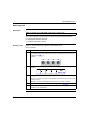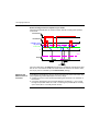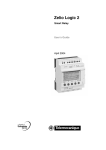
1
Zelio Logic 2
Smart Relay
User’s Manual
SR2MAN01EN
3500714303
11/2005
2
Table of Contents
Safety Information . . . . . . . . . . . . . . . . . . . . . . . . . . . . . . . . . . . . 7
About the Book . . . . . . . . . . . . . . . . . . . . . . . . . . . . . . . . . . . . . . . 9
Part I Initial Power up and Discovering . . . . . . . . . . . . . . . . . . 11
Presentation . . . . . . . . . . . . . . . . . . . . . . . . . . . . . . . . . . . . . . . . . . . . . . . . . . . . 11
Chapter 1
Initial Power up and Discovering . . . . . . . . . . . . . . . . . . . . . . . 13
Presentation . . . . . . . . . . . . . . . . . . . . . . . . . . . . . . . . . . . . . . . . . . . . . . . . . . . .
Safety . . . . . . . . . . . . . . . . . . . . . . . . . . . . . . . . . . . . . . . . . . . . . . . . . . . . . . . . .
Presentation of the Smart Relay Front Panel . . . . . . . . . . . . . . . . . . . . . . . . . . .
Characteristics and Connections. . . . . . . . . . . . . . . . . . . . . . . . . . . . . . . . . . . . .
Control Keys on the Front Panel of the Smart Relay . . . . . . . . . . . . . . . . . . . . .
Examples. . . . . . . . . . . . . . . . . . . . . . . . . . . . . . . . . . . . . . . . . . . . . . . . . . . . . . .
13
14
17
20
21
24
Part II Functions Accessible from the Front Panel . . . . . . . . . 29
At a Glance . . . . . . . . . . . . . . . . . . . . . . . . . . . . . . . . . . . . . . . . . . . . . . . . . . . . . 29
Chapter 2
Overview of the Functions Accessible from the Front Panel. 31
Functions Accessible from the Front Panel of the Smart Relay . . . . . . . . . . . . . 31
Chapter 3
INPUTS-OUTPUTS Screen . . . . . . . . . . . . . . . . . . . . . . . . . . . . . 33
At a Glance . . . . . . . . . . . . . . . . . . . . . . . . . . . . . . . . . . . . . . . . . . . . . . . . . . . . . 33
INPUTS-OUTPUTS Screen . . . . . . . . . . . . . . . . . . . . . . . . . . . . . . . . . . . . . . . . 34
TEXT and DISPLAY screen . . . . . . . . . . . . . . . . . . . . . . . . . . . . . . . . . . . . . . . . 36
Chapter 4
PROGRAMMING Menu . . . . . . . . . . . . . . . . . . . . . . . . . . . . . . . . 39
Presentation . . . . . . . . . . . . . . . . . . . . . . . . . . . . . . . . . . . . . . . . . . . . . . . . . . . .
Rules for Entering Ladder Diagrams . . . . . . . . . . . . . . . . . . . . . . . . . . . . . . . . . .
Method for Entering a Contact or Coil . . . . . . . . . . . . . . . . . . . . . . . . . . . . . . . . .
Entering a Link . . . . . . . . . . . . . . . . . . . . . . . . . . . . . . . . . . . . . . . . . . . . . . . . . .
Entry of Function Block Parameters . . . . . . . . . . . . . . . . . . . . . . . . . . . . . . . . . .
Deletion and Insertion of Diagram Lines . . . . . . . . . . . . . . . . . . . . . . . . . . . . . . .
Chapter 5
39
41
43
45
47
49
PARAMETERS Menu . . . . . . . . . . . . . . . . . . . . . . . . . . . . . . . . . 51
PARAMETERS Menu . . . . . . . . . . . . . . . . . . . . . . . . . . . . . . . . . . . . . . . . . . . . . 51
3
Chapter 6
MONITORING Menu . . . . . . . . . . . . . . . . . . . . . . . . . . . . . . . . . . 53
MONITORING Menu . . . . . . . . . . . . . . . . . . . . . . . . . . . . . . . . . . . . . . . . . . . . . . 53
Chapter 7
RUN/STOP Menu . . . . . . . . . . . . . . . . . . . . . . . . . . . . . . . . . . . . 55
RUN/STOP Menu . . . . . . . . . . . . . . . . . . . . . . . . . . . . . . . . . . . . . . . . . . . . . . . . 55
Chapter 8
CONFIGURATION Menu . . . . . . . . . . . . . . . . . . . . . . . . . . . . . . 59
Presentation. . . . . . . . . . . . . . . . . . . . . . . . . . . . . . . . . . . . . . . . . . . . . . . . . . . . . 59
PASSWORD Menu . . . . . . . . . . . . . . . . . . . . . . . . . . . . . . . . . . . . . . . . . . . . . . . 60
FILTER Menu. . . . . . . . . . . . . . . . . . . . . . . . . . . . . . . . . . . . . . . . . . . . . . . . . . . . 63
Zx KEYS Menu . . . . . . . . . . . . . . . . . . . . . . . . . . . . . . . . . . . . . . . . . . . . . . . . . . 64
WATCHDOG CYCLE Menu. . . . . . . . . . . . . . . . . . . . . . . . . . . . . . . . . . . . . . . . . 65
Chapter 9
CLEAR PROGRAM Menu . . . . . . . . . . . . . . . . . . . . . . . . . . . . . 67
CLEAR PROG Menu. . . . . . . . . . . . . . . . . . . . . . . . . . . . . . . . . . . . . . . . . . . . . . 67
Chapter 10
TRANSFER Menu . . . . . . . . . . . . . . . . . . . . . . . . . . . . . . . . . . . . 69
TRANSFER Menu . . . . . . . . . . . . . . . . . . . . . . . . . . . . . . . . . . . . . . . . . . . . . . . . 69
Chapter 11
VERSION Menu . . . . . . . . . . . . . . . . . . . . . . . . . . . . . . . . . . . . . 73
VERSION Menu. . . . . . . . . . . . . . . . . . . . . . . . . . . . . . . . . . . . . . . . . . . . . . . . . . 73
Chapter 12
LANGUAGE Menu . . . . . . . . . . . . . . . . . . . . . . . . . . . . . . . . . . . 75
LANGUAGE Menu . . . . . . . . . . . . . . . . . . . . . . . . . . . . . . . . . . . . . . . . . . . . . . . . 75
Chapter 13
DEFAULT Menu . . . . . . . . . . . . . . . . . . . . . . . . . . . . . . . . . . . . . 77
FAULT Menu . . . . . . . . . . . . . . . . . . . . . . . . . . . . . . . . . . . . . . . . . . . . . . . . . . . . 77
Chapter 14
CHANGE DATE/TIME Menu. . . . . . . . . . . . . . . . . . . . . . . . . . . . 81
CHANGE DATE/TIME Menu . . . . . . . . . . . . . . . . . . . . . . . . . . . . . . . . . . . . . . . . 81
Chapter 15
CHANGE SUMMER/WINTER Menu . . . . . . . . . . . . . . . . . . . . . . 83
CHANGE SUMMER/WINTER Menu . . . . . . . . . . . . . . . . . . . . . . . . . . . . . . . . . . 83
Part III LD Language . . . . . . . . . . . . . . . . . . . . . . . . . . . . . . . . . . . 85
At a Glance . . . . . . . . . . . . . . . . . . . . . . . . . . . . . . . . . . . . . . . . . . . . . . . . . . . . . 85
Chapter 16
LD Language Elements . . . . . . . . . . . . . . . . . . . . . . . . . . . . . . . 87
At a Glance . . . . . . . . . . . . . . . . . . . . . . . . . . . . . . . . . . . . . . . . . . . . . . . . . . . . . 87
Introduction . . . . . . . . . . . . . . . . . . . . . . . . . . . . . . . . . . . . . . . . . . . . . . . . . . . . . 88
Discrete Inputs . . . . . . . . . . . . . . . . . . . . . . . . . . . . . . . . . . . . . . . . . . . . . . . . . . . 89
Zx Keys . . . . . . . . . . . . . . . . . . . . . . . . . . . . . . . . . . . . . . . . . . . . . . . . . . . . . . . . 91
Auxiliary Relays . . . . . . . . . . . . . . . . . . . . . . . . . . . . . . . . . . . . . . . . . . . . . . . . . . 93
Discrete (DISCR) Outputs . . . . . . . . . . . . . . . . . . . . . . . . . . . . . . . . . . . . . . . . . . 98
Timers . . . . . . . . . . . . . . . . . . . . . . . . . . . . . . . . . . . . . . . . . . . . . . . . . . . . . . . . 103
Counters . . . . . . . . . . . . . . . . . . . . . . . . . . . . . . . . . . . . . . . . . . . . . . . . . . . . . . 114
Fast Counter . . . . . . . . . . . . . . . . . . . . . . . . . . . . . . . . . . . . . . . . . . . . . . . . . . . 121
Counter Comparator . . . . . . . . . . . . . . . . . . . . . . . . . . . . . . . . . . . . . . . . . . . . . 132
4
Analog Comparators . . . . . . . . . . . . . . . . . . . . . . . . . . . . . . . . . . . . . . . . . . . . .
Clocks . . . . . . . . . . . . . . . . . . . . . . . . . . . . . . . . . . . . . . . . . . . . . . . . . . . . . . . .
Texts . . . . . . . . . . . . . . . . . . . . . . . . . . . . . . . . . . . . . . . . . . . . . . . . . . . . . . . . .
LCD Screen Backlighting . . . . . . . . . . . . . . . . . . . . . . . . . . . . . . . . . . . . . . . . .
Change to Summer / Winter Time. . . . . . . . . . . . . . . . . . . . . . . . . . . . . . . . . . .
Modbus Inputs/Outputs . . . . . . . . . . . . . . . . . . . . . . . . . . . . . . . . . . . . . . . . . . .
Message . . . . . . . . . . . . . . . . . . . . . . . . . . . . . . . . . . . . . . . . . . . . . . . . . . . . . .
134
139
143
145
146
148
149
Part IV Creating and Debugging an Application . . . . . . . . . . . 151
Presentation . . . . . . . . . . . . . . . . . . . . . . . . . . . . . . . . . . . . . . . . . . . . . . . . . . . 151
Chapter 17
Implementing a Basic Application . . . . . . . . . . . . . . . . . . . . . 153
Presentation . . . . . . . . . . . . . . . . . . . . . . . . . . . . . . . . . . . . . . . . . . . . . . . . . . .
Presentation of Ladder Diagrams . . . . . . . . . . . . . . . . . . . . . . . . . . . . . . . . . . .
Using the Reverse Function . . . . . . . . . . . . . . . . . . . . . . . . . . . . . . . . . . . . . . .
Notation Used by the Smart Relay . . . . . . . . . . . . . . . . . . . . . . . . . . . . . . . . . .
Application: Implementing a Two-way Switch . . . . . . . . . . . . . . . . . . . . . . . . . .
Chapter 18
Debugging an Application . . . . . . . . . . . . . . . . . . . . . . . . . . . . 169
Presentation . . . . . . . . . . . . . . . . . . . . . . . . . . . . . . . . . . . . . . . . . . . . . . . . . . .
Introduction . . . . . . . . . . . . . . . . . . . . . . . . . . . . . . . . . . . . . . . . . . . . . . . . . . . .
Dynamic Mode Ladder Diagrams . . . . . . . . . . . . . . . . . . . . . . . . . . . . . . . . . . .
Dynamic Mode Function Block Parameters . . . . . . . . . . . . . . . . . . . . . . . . . . .
Dynamic Mode Menus. . . . . . . . . . . . . . . . . . . . . . . . . . . . . . . . . . . . . . . . . . . .
Smart Relay Reaction to a Power Failure . . . . . . . . . . . . . . . . . . . . . . . . . . . . .
Chapter 19
153
154
156
159
161
169
170
172
174
175
176
Backup and Transfer of Ladder Diagrams" . . . . . . . . . . . . . . 179
Saving and Transferring Ladder Diagrams . . . . . . . . . . . . . . . . . . . . . . . . . . . . 179
Chapter 20
Sample Application . . . . . . . . . . . . . . . . . . . . . . . . . . . . . . . . . 181
Presentation . . . . . . . . . . . . . . . . . . . . . . . . . . . . . . . . . . . . . . . . . . . . . . . . . . .
Specifications . . . . . . . . . . . . . . . . . . . . . . . . . . . . . . . . . . . . . . . . . . . . . . . . . .
Specification Analysis . . . . . . . . . . . . . . . . . . . . . . . . . . . . . . . . . . . . . . . . . . . .
Implementing the Solution. . . . . . . . . . . . . . . . . . . . . . . . . . . . . . . . . . . . . . . . .
181
182
183
185
Part V Diagnostics . . . . . . . . . . . . . . . . . . . . . . . . . . . . . . . . . . . 189
Presentation . . . . . . . . . . . . . . . . . . . . . . . . . . . . . . . . . . . . . . . . . . . . . . . . . . . 189
Chapter 21
Diagnostics . . . . . . . . . . . . . . . . . . . . . . . . . . . . . . . . . . . . . . . . 191
Presentation . . . . . . . . . . . . . . . . . . . . . . . . . . . . . . . . . . . . . . . . . . . . . . . . . . . 191
Smart Relay Messages . . . . . . . . . . . . . . . . . . . . . . . . . . . . . . . . . . . . . . . . . . . 192
Frequently Asked Questions . . . . . . . . . . . . . . . . . . . . . . . . . . . . . . . . . . . . . . . 193
Index
. . . . . . . . . . . . . . . . . . . . . . . . . . . . . . . . . . . . . . . . . . . . . 195
5
6
Safety Information
§
Important Information
NOTICE
Read these instructions carefully, and look at the equipment to become familiar with
the device before trying to install, operate, or maintain it. The following special
messages may appear throughout this documentation or on the equipment to warn
of potential hazards or to call attention to information that clarifies or simplifies a
procedure.
The addition of this symbol to a Danger or Warning safety label indicates
that an electrical hazard exists, which will result in personal injury if the
instructions are not followed.
This is the safety alert symbol. It is used to alert you to potential personal
injury hazards. Obey all safety messages that follow this symbol to avoid
possible injury or death.
DANGER
DANGER indicates an imminently hazardous situation, which, if not avoided, will
result in death, serious injury, or equipment damage.
WARNING
WARNING indicates a potentially hazardous situation, which, if not avoided, can result
in death, serious injury, or equipment damage.
CAUTION
CAUTION indicates a potentially hazardous situation, which, if not avoided, can result
in injury or equipment damage.
SR2MAN01EN 11/2005
7
Safety Information
PLEASE NOTE
Electrical equipment should be serviced only by qualified personnel. No responsibility is
assumed by Schneider Electric for any consequences arising out of the use of this
material. This document is not intended as an instruction manual for untrained persons.
© 2005 Schneider Electric. All Rights Reserved.
8
SR2MAN01EN 11/2005
About the Book
At a Glance
Document Scope
This manual describes the use of functions accessible from the front panel of the
smart relay.
This document is divided into 5 parts and addresses the following topics:
Part I: Powering up and Discovering the Smart Relay.
z General presentation of the smart relay.
z Part II: Functions Accessible from the Front Panel.
z Description of the interface and the menus of the smart relay.
z Part III: LD Language.
z Description of automation functions available for programming in LADDER.
z Part IV: Creating, Debugging and Saving an Application.
z Example of programming
z Presentation of tools for debugging and saving an application.
z Part V: Diagnostics.
z Help for finding solutions to operating problems.
z
Validity Note
The information in this manual applies only to smart relays of the Zelio 2 series.
User Comments
We welcome your comments about this document. You can reach us by e-mail at
[email protected]
SR2MAN01EN 11/2005
9
About the Book
10
SR2MAN01EN 11/2005
Initial Power up and Discovering
I
Presentation
Subject of this
Section
This section presents the operation and main characteristics of the smart relay.
What's in this
Part?
This part contains the following chapters:
Chapter
1
SR2MAN01EN 11/2005
Chapter Name
Initial Power up and Discovering
Page
13
11
Initial Power up and Discovering.
12
SR2MAN01EN 11/2005
Initial Power up and Discovering
1
Presentation
Subject of this
Chapter
This chapter presents the operation and main characteristics of the smart relay.
What's in this
Chapter?
This chapter contains the following topics:
SR2MAN01EN 11/2005
Topic
Page
Safety
14
Presentation of the Smart Relay Front Panel
17
Characteristics and Connections
20
Control Keys on the Front Panel of the Smart Relay
21
Examples
24
13
Initial Power up and Discovering
Safety
Preliminary
Advice
Preliminary advice and general safety precautions relating to installing smart relays:
z
z
z
z
z
z
z
z
z
z
z
z
z
z
z
z
z
z
14
Remember that only qualified personnel are authorized to implement the smart relay.
Read this instruction sheet and the User Guide to learn the procedures prior to
installing, wiring, operating, maintaining of controlling the smart relay.
The end user should keep this User Guide and the product instructions sheet.
Install the smart relay by following the instructions in the instruction bulletin and the User
Guide. Improper installation may result in failure or malfunction of the smart relay.
Make the necessary ground and short circuit the connections.
Check the operating conditions, as described in the User Guide. If you are unsure
of the technical characteristics, contact Schneider Electric.
Fluctuations or variations in the power supply voltage should not exceed the
tolerance thresholds stated in the technical characteristics, as they may lead to
operating failures and potentially dangerous situations.
Take any steps necessary to ensure that an application interrupted by a power
failure continues to operate correctly after restoring power and make sure also
that no dangerous situation whatsoever arises.
Take any steps necessary to prevent involuntary activation of the relay.
Automation and control devices must be installed in areas where they are
protected against any risk of involuntary activation.
Ensure that all connections to the control system meet applicable safety standards.
Ensure that you comply with all applicable standards for emergency stop systems in
order to avoid potentially dangerous situations. Ensure that releasing the emergency
stop system does not cause the automated system to suddenly restart.
Install the smart relay only in environments described in the User Guide. Do not
use the smart relay in environments subject to excessive temperatures, elevated
relative humidity, condensation, corrosive gases, or excessive shocks.
The smart relay should be used in "Pollution level 2" environments. This level
defines the effect of pollution on the insulation.
Definition of level 2 Pollution: Only non-conductive pollution arises, except for
occasional temporary conductivity caused by condensation. Do not use smart
relays in environments lower than those specified in IEC Standard 60664-1.
Use appropriate wires according to current and voltage requirements. Tighten the
screws of the terminal according to the specified torque.
Use an IEC 60127 approved fuse, in conformity with the requirements for current
and voltage, to protect the power line and output circuits. This is not required
when a device including a smart relay is intended for Europe.
Use an EU-approved switch. This is not required when a device including a smart
relay is intended for Europe.
SR2MAN01EN 11/2005
Initial Power up and Discovering
DANGER
HAZARD OF ELECTRIC SHOCK, EXPLOSION, OR ARC FLASH
Turn power off before installing, removing, wiring or maintaining.
Failure to follow this instruction will result in death, serious injury, or
equipment damage.
WARNING
RISK OF EXPLOSION
Precautions:
z Compliant with standard CSA C22.2 No 213: This equipment is designed for
use in Class 1, Division 2, Groups A, B, C, D or in non-dangerous locations only.
Replacement of components may compromise the suitability to this specified
environment.
z Ensure that the power voltage and its tolerances are compatible with those of
the smart relay.
z Do not disconnect the equipment as long as the power supply has not been cut
off or the zone is not safe.
z This product contains a battery. Do not place the smart relay in fire.
Failure to follow this instruction can result in death, serious injury, or
equipment damage.
WARNING
RISK OF ELECTRIC SHOCK OR FIRE
Precautions:
z The smart relay is solely intended for installation in an enclosure. Do not install
the smart relay outside of an enclosure.
z Ensure that no metal fragment or wiring material falls into the enclosure of the
smart relay. Foreign bodies may lead to fire, material damage or malfunction.
Failure to follow this instruction can result in death, serious injury, or
equipment damage.
SR2MAN01EN 11/2005
15
Initial Power up and Discovering
WARNING
INVOLUNTARY OPERATION OF EQUIPMENT
Precautions:
z Power off the smart relay prior to installation, deinstallation, wiring,
maintenance or operation of the unit.
z The emergency stop and the locking circuits should be configured in the
software program of the smart relay.
z In the event of failure of the relays or transistors in the output modules of the
smart relay, the outputs should remain activated or deactivated. For output
signals that might lead to serious accidents, install a control circuit external to
the smart relay.
z Install the modules according to the environmental operation conditions
specified in the instruction bulletin.
z Do not attempt to dismantle, repair or modify the smart modules.
z Use an IEC 60127 approved fuse, in conformity with the requirements for
current and voltage, to protect the power line and output circuits.
Failure to follow this instruction can result in death, serious injury, or
equipment damage.
DANGER
RISK OF UNEXPECTED EQUIPMENT OPERATION
Special case of the use of the SR2COM01 modem communication extension.
Sending commands may lead to modification of the status of smart relay outputs
or accidental enabling of controlled equipment.
It is important to:
z Know how the commands will affect the process or the controlled equipment,
z Take any preventive measures necessary to ensure safety when making
modifications.
Failure to follow this instruction will result in death, serious injury, or
equipment damage.
16
SR2MAN01EN 11/2005
Initial Power up and Discovering
Presentation of the Smart Relay Front Panel
Introduction
Smart relays are designed to simplify the electrical wiring of intelligent solutions. A
smart relay is very simple to implement. Its flexibility and its high performance allow
users to save significant amounts of time and money.
This User’s Guide is intended for people who do not have an in-depth knowledge of
automation systems and who would like to be able to implement smart relays.
SR2MAN01EN 11/2005
17
Initial Power up and Discovering
Description of
the Smart Relay
Front Panel
The illustration below presents the elements of the front panel of the smart relay:
2
3
4
5
1
-
+
I1
24 VDC
I2 I3
I4
Inputs I1...I4
24 VDC
IB
IC ID
IE
IB... IE
Analog or 24 VDC
SR2 B122BD
1234
BCDE
STOP LD
THU 25 SEP 16 : 40
1234
6
Menu / OK
7
10
8
Outputs
Q1 ... Q4: Relay 8A
1
2
1
Q1
2
Q2
1
2
Q3
1
2
Q4
1
9
Prompt Element
18
1
Retractable mounting feet.
2
Screw terminal block for the power supply.
3
LCD display, 4 lines, 18 characters.
4
Screw terminal block for discrete inputs.
5
Screw terminal block for analog inputs.
0-10 Volts, usable in discrete input mode depending on model.
6
Slot for backup memory or PC connection cable.
7
Shift key (white).
8
Menu/OK key (green) for selection and confirmation.
9
Relay output screw terminal block.
10
Navigation keys (gray) or after configuring Z pushbuttons.
SR2MAN01EN 11/2005
Initial Power up and Discovering
Description of
the LCD
The illustration below presents an example of LCD display elements when
displaying the INPUT-OUTPUT screen:
2
1
2
3
4
1234
BCDE
STOP LD
THU 25 SEP 16 : 40
1234
5
1
2
3
4
Menu / OK
Prompt Element
1
Input status* display (B...E represent the analog inputs, also may be used as DISCR).
2
Display of the operating mode (RUN/STOP) and programming mode (LD/FBD).
3
Display of the date (day and time for products with clock).
4
Output status display.
5
Contextual menus / pushbuttons / icons indicating the operating modes.
* An ACTIVE input or output is displayed in reverse video.
SR2MAN01EN 11/2005
19
Initial Power up and Discovering
Characteristics and Connections
Introduction
Here is detailed information on the characteristics of DC smart relay connections.
Recommended
connection
It is recommended to connect the smart relay to a regulated DC power supply:
Regulated
220 V
Possible
Connection
/=
ABL7R
24 V=
RECOMMENDED
It is possible to connect the smart relay to a rectified filtered regulated power supply:
Rectified and filtered
U max
POSSIBLE
U min
Provided that it verify the following characteristics, according to the type of smart
relay:
Prohibited
Connection
SR2 ... BD
SR2 ... JD
U max < 30 V
U min > 19.2 V
U max < 14,4 V
U min > 10.4 V
It is prohibited to connect the smart relay to a rectified non-filtered power supply:
Rectified non filtered
PROHIBITED
20
SR2MAN01EN 11/2005
Initial Power up and Discovering
Control Keys on the Front Panel of the Smart Relay
Description
The keys located on the front panel of the smart relay are used to configure, program
and control the application and monitor the application's progress.
Illustration:
2
PROGRAMMING
PARAMETERS
RUN / STOP
CONFIGURATION
Menu / OK
Note: The LCD screen is lit for 30 seconds when the user presses any of the
buttons on the front panel.
Shift Key
The Shift key is the white key located on the right side of the LCD screen.
When the Shift key is pressed, a contextual menu is displayed above the Z keys
(Ins, Del, Param, etc.).
Menu/OK Key
The Menu/OK key is the green key located below the LCD screen on the right side.
This key is used for all confirmations: Menu, sub-menu, program, parameter, etc.
Zx Keys
The Zx keys are the gray keys aligned from left (Z1) to right (Z4) and located under
the LCD. The arrows indicating the movement direction associated with navigation
are marked above the keys.
The navigation keys are used to move left or right, down or up.
The position on the screen appears as a flashing zone:
Square for a position that corresponds to a contact (only in programming mode),
z Round for a link (only in programming mode).
z
Note: When the keys may be used for other actions apart from navigation, a
contextual menu bar is displayed (e.g.: 1, 2, 3 and 4 as Zx-type keys).
SR2MAN01EN 11/2005
21
Initial Power up and Discovering
Contextual
Menus
When the cursor is placed on a modifiable parameter, if the Shift key is pressed, a
contextual menu appears.
Illustration:
ins.
-
+
Param
Del.
Menu / OK
Using the contextual menu functions:
z
z
z
z
z
z
+ / -: Used to scroll through the various possible values of the selected field (types
of inputs, outputs, automation functions, numbers, numerical values, etc),
Ins.: Inserts a line,
Del.: Deletes the selected element, or the entire line if it is empty,
Param.: Displays the specific parameter screen for the automation function
(visible only if the automation function contains a parameter),
← ↑ ↓ →: Direction of the connection (visible only if the cursor is placed over a
link box),
1 2 3 4: This line appears when the keys are used as Zx key-type inputs in a
program.
Illustration:
Menu / OK
The key indicates that the program is password-protected.
Illustration:
Menu / OK
1
2
3
1: Indicates the state of the smart relay. In RUN it is in motion, in STOP it is immobile.
2: Indicates that faults have appeared (see FAULT menu).
3: The smart relay is physically connected to the programming software.
22
SR2MAN01EN 11/2005
Initial Power up and Discovering
Examples
Introduction
We will now see two examples of how to use the smart relay’s keys.
Language
Selection
Example 1: Here are details on how to select the language of the smart relay:
Step Action
1
Powering up
On initial powering-up, the INPUT-OUTPUT screen is displayed (See: INPUTSOUTPUTS Screen, p. 34). By default, the selected language is English.
View:
1234
BCDE
STOP LD
FRI 25 NOV 16 : 40
1234
2
Menu / OK
From the INPUT-OUTPUT screen, enter the MAIN menu
, then go to the
CONFIGURATION menu LANGUAGE, by pressing 7 times on the down navigation
key
View:
.
CLEAR PROG
TRANSFER
VERSION
LANGUAGE
Note: the selected command flashes.
SR2MAN01EN 11/2005
23
Initial Power up and Discovering
Step Action
3
Enter in the language selection menu.
Menu / OK
View:
ENGLISH
FRANCAIS
DEUTSCH
ITALIANO
Note: The activated option flashes and it is also indicated by a black diamond.
4
Select and confirm the language (the selection is shown in flashing text).
Menu / OK
or
then
The Menu/OK button is used to confirm the selection of the new language. The
display returns to the MAIN menu when the smart relay is in STOP mode.
View:
CLEAR PROG
TRANSFER
VERSION
LANGUAGE
24
SR2MAN01EN 11/2005
Initial Power up and Discovering
Step Action
5
Return to the INPUT-OUTPUT screen using the left navigation key.
View:
1234
BCDE
STOP LD
FRI 25 NOV 16 : 40
1234
Modification of
Date and Hour
Example 2: Here are details on procedure to follow to modify the date and time of
the initial power up or following a long lasting power failure.
Step Action
1
From the INPUT-OUTPUT screen, enter the MAIN menu, then go to the CHANGE D/
H menu:
Menu / OK
then
9 times in LD mode
7 times in FBD mode
View:
VERSION
LANGUAGE
DEFAULT
CHANGE D/H
SR2MAN01EN 11/2005
25
Initial Power up and Discovering
Step Action
2
Enter the date and hour configuration menu:
Menu / OK
View:
CHANGE D/H
THU 07 JUL
2003
16 : 27 30 s
CAL
0 2 secs / WK
3
Select the parameter to modify using the arrows (the selection is highlighted by the
blinking of the parameter):
or
Modify the parameter using the navigation keys:
+
or
Then confirm with the Menu/OK key:
Menu / OK
The Menu/OK button is used to confirm the modifications. The display returns to the
MAIN menu when the smart relay is in STOP mode).
View:
VERSION
LANGUAGE
DEFAULT
CHANGE D/H
26
SR2MAN01EN 11/2005
Initial Power up and Discovering
Step Action
4
Return to the INPUT-OUTPUT screen
View:
1234
BCDE
STOP LD
FRI 25 NOV 16 : 40
1234
SR2MAN01EN 11/2005
27
Initial Power up and Discovering
28
SR2MAN01EN 11/2005
Functions Accessible from the
Front Panel
II
At a Glance
Subject of this
Section
This section describes the functions that can be accessed from the front panel of the
smart relay.
What's in this
Part?
This part contains the following chapters:
SR2MAN01EN 11/2005
Chapter
Chapter Name
Page
2
Overview of the Functions Accessible from the Front Panel
31
3
INPUTS-OUTPUTS Screen
33
4
PROGRAMMING Menu
39
5
PARAMETERS Menu
51
6
MONITORING Menu
53
7
RUN/STOP Menu
55
8
CONFIGURATION Menu
59
9
CLEAR PROGRAM Menu
67
10
TRANSFER Menu
69
11
VERSION Menu
73
12
LANGUAGE Menu
75
13
DEFAULT Menu
77
14
CHANGE DATE/TIME Menu
81
15
CHANGE SUMMER/WINTER Menu
83
29
Functions Accessible from the Front Panel
30
SR2MAN01EN 11/2005
Overview of the Functions
Accessible from the Front Panel
2
Functions Accessible from the Front Panel of the Smart Relay
Description
From the front panel of the smart relay, you may:
z
z
z
z
Program (in LD mode),
Configure,
Control the application,
Monitor the performance of the application.
Illustration:
2
PROGRAMMING
PARAMETERS
RUN / STOP
CONFIGURATION
Menu / OK
The line flashes to indicate where you are positioned.
The up triangle on the right side of the LCD screen indicates that possible up
options exist. The down triangle indicates that possible down options exist.
To return to the previous menu, press left navigation key.
Note: The LCD screen is lit for 30 seconds when the user presses any of the
buttons on the front panel.
SR2MAN01EN 11/2005
31
Overview of the Functions Accessible from the Front Panel
Managing Menus
The INPUTS-OUTPUTS screen is displayed by default whether the mode is LD or FBD.
Pressing the Menu/OK key switches the display from the INPUTS-OUTPUTS
screen to the MAIN menu.
The menu on the first row which is selected by default (flashing). The and
navigation keys can be used to place the cursor over the other menus.
Press the green Menu/OK key to display the screen corresponding to the selected
menu or to move onto the first sub-menu.
Differences
Between LD and
FBD Modes
Certain menus are specific to either LD or FBD mode.
Menu
LD
FBD
PROGRAMMING
MONITORING
PARAMETERS
RUN / STOP
CONFIGURATION
PASSWORD
FILTER
Zx KEYS
WATCHDOG CYCLE
CLEAR PROG.
TRANSFER
VERSION
LANGUAGE
FAULT
CHANGE D/T
CHANGE SUMM/WINT
Configuring
Extensions
32
Extensions added to the smart relay may only be configured from the programming
software. See on-line help of the programming software for more information.
SR2MAN01EN 11/2005
INPUTS-OUTPUTS Screen
3
At a Glance
Subject of this
Chapter
This chapter describes the characteristics of the INPUTS-OUTPUTS screen.
What's in this
Chapter?
This chapter contains the following topics:
SR2MAN01EN 11/2005
Topic
Page
INPUTS-OUTPUTS Screen
34
TEXT and DISPLAY screen
36
33
INPUTS-OUTPUTS Screen
INPUTS-OUTPUTS Screen
Description
This is the highest-level interface. It is displayed by default, when no (TEXT or
DISPLAY) display function is active and regardless of:
z
z
The programming type: LD or FBD,
The mode: STOP or RUN.
Illustration:
2
3
2
1
123456
4
5
STOP LD
MON 22 SEP 15:51
1234
6
2
Menu / OK
The INPUTS-OUTPUTS screen can be used to view:
1.
2.
3.
4.
5.
6.
The state of the inputs: 1 to 9, A to P,
The mode used: LD/FBD,
The Operating mode: RUN / STOP,
The date and time for products with a clock,
The state of the outputs: 1 to 9, A to G,
Z push buttons: 1 to 4.
In Simulation mode or Monitoring mode when the program is in RUN, the active
states of the Inputs/Outputs are indicated in reverse video.
34
SR2MAN01EN 11/2005
INPUTS-OUTPUTS Screen
Access to the
Main Menu
Pressing the Menu/OK key switches the display from the INPUTS-OUTPUTS
screen to the main menu:
z
z
z
z
z
z
z
z
z
z
z
z
PROGRAMMING (LD STOP mode),
MONITORING (LD RUN mode),
PARAMETERS,
RUN / STOP,
CONFIGURATION (STOP mode),
CLEAR PROG. (LD STOP mode),
TRANSFER (STOP mode),
VERSION,
LANGUAGE,
FAULT,
CHANGE D/T,
CHANGE SUMM/WINT.
The display automatically returns to the INPUTS-OUTPUTS menu on exiting all
other menus and sub-menus.
SR2MAN01EN 11/2005
35
INPUTS-OUTPUTS Screen
TEXT and DISPLAY screen
Description
The display functions are used to display text or numerical values (current value,
preset value, etc.) on the LCD display instead of the INPUTS-OUTPUTS:
z
z
In LD mode: A TEXT function is active,
in FBD mode: A DISPLAY function is active.
Illustration:
2
Value counter1
C1
C = 00001
Date
28/11/2003
2
Menu / OK
If several display functions are active simultaneously:
z In LD mode: The highest block number is displayed. There are 16 TEXT-type
blocks numbered from 1 to 9 then from A to G,
z In FBD mode: The superposition of all of the FBD DISPLAY screens is displayed,
for up to 32 blocks. If more than 32 FBD DISPLAY blocks are active, the screens
of the 32 FBD DISPLAY blocks with the lowest numbers are superposed.
Note: The display functions are programmable only from the programming
software (see the on-line help for the programming software for more information).
Switching
Between the
Screens
Switching between the screens
It is however possible to go from the TEXT (LD) or DISPLAY (FBD) screen to the
INPUTS-OUTPUTS screen and vice-versa.
To do this, proceed as follows:
Step
1
36
Action
Press and hold down the Shift key and press the Menu/OK key.
SR2MAN01EN 11/2005
INPUTS-OUTPUTS Screen
Modify Displayed
Values
In RUN mode, when the TEXT / DISPLAY screen is displayed, it is possible to
modify, from the front panel, the displayed values whose modification was
authorized in the block function parameters window.
To do this, proceed as follows:
Step
Action
1
Press the Shift key (white key) to display the contextual menu.
Result: Param is displayed at the bottom of the screen.
2
Press the key (without releasing the Shift key) to display the contextual menu.
Result: The parameter which can be modified flashes and the following
contextual menu is displayed:
-
+
Menu / OK
SR2MAN01EN 11/2005
3
Select the parameter to be modified using the navigation keys and from the
contextual menu (the value which are available for modification flash).
4
Modify the parameter value with the + ( ) and - ( ) keys from the contextual menu.
5
Confirm the changes by pressing the Menu/OK key.
Result: The display returns to the INPUTS-OUTPUTS screen or the TEXT /
DISPLAY screen.
37
INPUTS-OUTPUTS Screen
38
SR2MAN01EN 11/2005
PROGRAMMING Menu
4
Presentation
Subject of this
Chapter
This chapter describes the characteristics of the PROGRAMMING menu specific to
LD mode / smart relay in STOP mode.
This function lets the user enter the ladder diagrams that will work on the smart relay.
This program is written only using a ladder diagram LD.
Illustration:
2
I1
I2
I1
RT1
M3
T1
SM1
TT1
Menu / OK
Note: The smart relays to which have been added an Input/Output extension are
programmable only in FBD mode from the programming software.
See on-line help of the programming software for more information.
SR2MAN01EN 11/2005
39
PROGRAMMING Menu
What's in this
Chapter?
40
This chapter contains the following topics:
Topic
Page
Rules for Entering Ladder Diagrams
41
Method for Entering a Contact or Coil
43
Entering a Link
45
Entry of Function Block Parameters
47
Deletion and Insertion of Diagram Lines
49
SR2MAN01EN 11/2005
PROGRAMMING Menu
Rules for Entering Ladder Diagrams
Description
A smart relay allows you to enter 120 line Ladder diagrams.
The smart relay’s display screen is used to display these lines, 4 at a time, in the
following manner:
1
2
3
I1-H1-C1-M1-T2-CC1
I2
Z1 ----------Z3
4
Prompt
Element
1
Column reserved for contacts (conditions).
2
Column reserved for contacts (conditions) and for links.
3
Column reserved for coils (actions).
4
Column reserved for links.
Each line comprises 5 fields each with 2 characters reserved for contacts
(conditions). The 4 central columns can also accept links. The last three-character
column is reserved for coils (actions).
Links must be entered between the contact and coil columns.
A ladder diagram is entered into the smart relay using the front panel keys (see
Control Keys on the Front Panel of the Smart Relay, p. 21).
SR2MAN01EN 11/2005
41
PROGRAMMING Menu
Data Entry Rules
Make sure you respect the following rules when you enter a ladder diagram:
Rules
Each coil must only be
entered once in the right
hand column
Incorrect
I1-------------[Q1
I2-I3----------TT1
T1-------------[Q1
Z1
Elements used as contacts
may be entered as many
times as necessary in the 5
left hand columns.
Links must always run
from left to right.
Correct
I1-------------[Q1
T1
I2-I3----------TT1
Z1
I1-------------TT1
T1-------------[Q1
I3-T1----------[M2
I1-M2----------[Q2
I1-I2-I3
-I4-I5-I6-[Q1
If S coils (SET) are used in If no R (Reset) coils are used,
a diagram, also use an R the corresponding coil will
(Reset) coil.
always be set to 1.
I1-I2-I3-------[M1
M1----I4-I5-I6-[Q1
An R (Reset) coil must be used
for reset purposes.
Note: Smart relays run programs from top to bottom and from left to right.
42
SR2MAN01EN 11/2005
PROGRAMMING Menu
Method for Entering a Contact or Coil
Description
Note: Accessible only in LD mode / smart relay in STOP mode.
This section describes the procedures for performing the following operations:
z
z
z
Entering an element,
Modifying an element,
Deleting an Element.
This is valid for : contact or coil elements, whether the parameters can be set or not.
Entering an
Element
When entering an element, the following rules must be observed:
z
z
Contact: In any column except the last,
Coil: Only in the last column.
The presence of a square, flashing cursor means an element can be inserted.
Entry procedure:
Step Action
1
Place the flashing cursor at the required location.
The navigation keys can be used move the cursor in the direction of the arrows on the
navigation keys
.
Illustration:
2
Press the Shift key to display the contextual menu.
Illustration:
ins.
-
+
Del.
Menu / OK
By simultaneously pressing Shift and one of the
(- and +) keys, the first letter
of the element is inserted: I for a contact and Q for a coil, followed by the number 1.
3
Choose the type of element desired by pressing simultaneously on Shift and + or -. This
makes the different types of elements scroll down cyclically, in the following order:
z For the contacts: I, i, Z, z, M, m, Q, q, T, t, C, c, K, k, V, v, A, a, H, h, W, w, S, s.
z For the coils: M, Q, T, C, K, X, L, S.
See the chapterLD Language Elements, p. 87.
SR2MAN01EN 11/2005
43
PROGRAMMING Menu
Step Action
4
Release the Shift key to have access to the navigation keys:
.
Pressing the key places the cursor over the corresponding number 1.
5
Simultaneously hold down the Shift and + keys to increment the number of the
element (2, 3, 4,..., 9, A, etc.).
Note: The numbers for functional blocks are limited to the number of blocks of the
type available in the smart relay. In the case of extensible smart relays, the inputs and
outputs numbers are used to program the extension to maximum size.
In entering a contact, once this step is completed, the entry is terminated.
In entering a coil, you must additionally select the function of the coil.
6
Release the Shift key to have access to the navigation keys:
7
Steps 7 to 9 are only necessary when entering a coil.
Position the cursor on the function of the coil by pressing twice on the
8
Select the desired function by pressing simultaneously on the Shift key and the + or
- key. This will scroll through the different coil functions available.
9
Release the Shift key to have access to the navigation keys:
.
key.
.
Note: Confirming some function block coils will bring-up a function block parameter
setting screen.
Modifying an
element,
To modify an existing control diagram element, simply:
Initialization
Status of contacts on program initialization:
z
z
z
z
Deleting an
Element
Position the pointer over the element to modify: Step 1 in the previous table,
Select the desired new element: Steps 3 to 6.
A contact in normally-open mode (direct state) is inactive,
A contact in normally-closed mode (reverse state) is active,
To delete an element, simply:
z
z
Place the cursor over the element to delete: Step 1,
Simultaneously press the Shift and Menu/OK keys.
Two scenarios are possible, depending on the position of the cursor at the time of
the deletion:
z
z
Cursor over an element: the element is deleted,
Cursor over an empty position of the line: the whole line is deleted.
Note: Generally, the deleted element must be replaced by a link.
44
SR2MAN01EN 11/2005
PROGRAMMING Menu
Entering a Link
Description
Note: Accessible only in LD mode / smart relay in STOP mode.
This section describes the procedures for performing the following operations:
z
z
z
Entering a Link
Entering links between elements,
Deleting links between elements,
Replacing a link with a contact.
Links are entered exclusively using the round flashing cursor.
Entry procedure:
Step Action
1
Place the flashing cursor at the required location.
The navigation keys can be used move the cursor in the direction of the arrows on the
navigation keys
Illustration:
2
.
Press the Shift key to display the contextual menu.
Illustration:
Del.
Menu / OK
3
SR2MAN01EN 11/2005
Trace connections by simultaneously pressing the Shift key and the navigation keys:
← ↑ ↓ →.
Shift and → to trace a connection to the position of the next contact or to the coil at
the end of the line.
Shift and ↑ ↓ to trace perpendicular connections to the previous or next line.
4
Release the Shift key to have access to the navigation keys:
5
Repeat the operation as many times as necessary to link the elements together
according to your requirements.
.
45
PROGRAMMING Menu
Modifying a Link
To modify an existing link, simply:
z
z
Deleting a Link
Place the cursor over the link to modify: step 1
Modify the link: Steps 2 to 5.
To delete a link, simply:
z
z
Place the cursor over the element to delete: step 1.
Simultaneously press the Shift and Menu/OK keys.
Two scenarios are possible, depending on the position of the cursor at the time of
the deletion:
z
z
Replacing a Link
with a Contact
To replace a link with a contact, simply:
z
z
46
Cursor over a link: The link is deleted,
Over an empty position of the line: The whole line is deleted.
Place the cursor (flashing square) over the link to transform: step 1.
Follow the element entry (See Method for Entering a Contact or Coil, p. 43)
procedure: Steps 3 to 6.
SR2MAN01EN 11/2005
PROGRAMMING Menu
Entry of Function Block Parameters
Description
Note: Accessible only in LD mode / smart relay in STOP mode.
When entering a control diagram, the parameters of the configurable automation
functions must be completed.
The automation functions with parameters are the following:
z
z
z
z
z
z
z
Accessibility of
parameters
SR2MAN01EN 11/2005
Auxiliary relays (See Auxiliary Relays, p. 93) (latching),
Discrete Outputs (See Discrete (DISCR) Outputs, p. 98) (latching),
Clocks (See Clocks, p. 139),
Analog Comparators (See Analog Comparators, p. 134),
Timers (See Timers, p. 103),
Counters (See Counters, p. 114),
Fast counters (See Fast Counter, p. 121).
Function block parameter setting can be accessed:
When entering the command diagram line,
z From the PARAMETERS menu if the block has not been padlocked.
z
47
PROGRAMMING Menu
Entering
Parameters on
Creation of the
Block
Parameters are entered in the same way, whatever the parameters screen:
Step Action
1
Enter the desired automation function: Step 1 of the element entry (See Method for
Entering a Contact or Coil, p. 43) procedure.
When the function has parameters, Param appears in the contextual menu (when the
Shift key is pressed).
Illustration:
ins.
-
+
Param
Del.
Menu / OK
2
Modifying the
Parameters of
Existing Blocks
48
Press and hold down the Shift key and press on Param (key
Result: The function’s parameter screen appears.
).
3
Use the navigation keys to move to the cursor over the modifiable parameters:
4
Modify the value of the parameter using the + and - keys, holding down Shift.
5
Confirm the modifications by pressing Menu/OK, which will open the confirmation window.
Confirm again by pressing the Menu/OK key to save.
.
To modify the parameters of an existing element, simply:
Step Action
1
Use the navigation keys to move the cursor over the element to modify: step 1 of the
element entry (See Method for Entering a Contact or Coil, p. 43) procedure.
2
At the same time, hold down Shift and the Param key to open the parameter window.
3
Carry out steps 3 to 5 above.
SR2MAN01EN 11/2005
PROGRAMMING Menu
Deletion and Insertion of Diagram Lines
Deletion
Note: Accessible only in LD mode / smart relay in STOP mode.
Diagram lines are deleted line-by line. The procedure is the following:
Step Action
1
Place the cursor over the line to delete.
2
Delete all the elements in the line (See Method for Entering a Contact or Coil, p. 43):
(Links, contacts and coils) to obtain an empty line.
3
Press the Shift key to display the contextual menu.
Illustration:
ins.
-
+
Del.
Menu / OK
Simultaneously pressing Shift and Del opens the confirmation window.
4
Confirm by pressing Menu/OK.
Note: It is possible to delete all diagram lines contained in the smart relay. In order
to do this, select the CLEAR PROG. option from the main menu, and confirm the
deletion of all the control diagram lines.
Insertion
The procedure is the following:
Step Action
SR2MAN01EN 11/2005
1
Place the cursor over the line located immediately below the line to create.
2
Press the Shift key to display the contextual menu.
3
Press the Ins key (while holding down the Shift key) to create the line.
49
PROGRAMMING Menu
50
SR2MAN01EN 11/2005
PARAMETERS Menu
5
PARAMETERS Menu
Description
This menu is used to enter and modify the application parameters directly on the
screen using the smart relay keys. This function can be accessed in the two modes:
LD and FBD, but the contents will be specific to the mode used.
If there are non-locked parameters to display they are listed in the window;
otherwise a NO PARAMETER message appears.
LD mode
Functions with parameters in LD mode:
z
z
z
z
z
z
z
Auxiliary relays (See Auxiliary Relays, p. 93) (latching),
Discrete Outputs (See Discrete (DISCR) Outputs, p. 98) (latching),
Clocks (See Clocks, p. 139),
Analog Comparators (See Analog Comparators, p. 134),
Timers (See Timers, p. 103),
Counters (See Counters, p. 114),
Fast counter (See Fast Counter, p. 121).
Only those functions used in the program and with parameters are listed in the
PARAMETERS menu.
SR2MAN01EN 11/2005
51
PARAMETERS Menu
FBD mode
Functions with parameters in FBD mode:
z
z
z
z
z
z
z
Numerical Constant-Type Inputs,
Clocks,
Gain,
Timers: TIMER A/C, TIMER B/H, TIMER Li,
Counters: PRESET COUNT,
Fast counter,
CAM block.
To access the parameters of the FBD blocks, you must know end enter the block
number. This number appears in the programming software on the wiring sheet at
the top right corner of the block.
Only those functions used in the program and with parameters are listed in the
PARAMETERS menu.
Parameter
Modification
Parameters in
RUN Mode
Parameter modification procedure:
Step Action
1
Place the cursor over the PARAMETERS menu in the main menu (PARAMETERS
flashing) and confirm by pressing the Menu/OK button.
Result: The parameters window opens to the first parameter.
2
Select the function to modify.
To access the required function, scroll through the function block numbers (navigation
keys and ) until you reach the right one.
3
Select the parameter to modify.
The and keys are used to place the cursor over the parameter to modify.
4
Modify the parameter using the + and - keys (
5
Confirm the modifications by pressing Menu/OK, which will open the confirmation
window.
6
Confirm again twice by pressing Menu/OK to save.
Result: The display returns to the INPUTS-OUTPUTS screen in RUN mode and to the
MAIN menu in STOP mode.
and
) of the contextual menu.
It is therefore possible to modify parameters in RUN mode dynamically as long as
they are not locked.
The modifications can be made:
z
z
52
From the PARAMETERS (See PARAMETERS Menu, p. 51) menu,
From the MONITORING (See MONITORING Menu, p. 53) (LD) menu: Move the
pointer over the function to be modified using the navigation keys and open the
parameters window from the contextual menu (Shift key).
SR2MAN01EN 11/2005
MONITORING Menu
6
MONITORING Menu
Description
Note: Accessible only in LD mode / smart relay in RUN mode.
MONITORING mode can be used to obtain a dynamic view of the state of the smart
relay inputs/outputs.
In this mode the wiring diagram appears as it does in the PROGRAMMING (See
PROGRAMMING Menu, p. 39) menu (smart relay in STOP mode), but appear in
reverse video when inputs or outputs are activated (white on black background).
Illustration:
I 1-i2----------[Q1
IB-------------TT1
T1-------------[Q2
H1-------------[M1
This mode is also used to dynamically modify the values of automation function
parameters if these are not locked.
SR2MAN01EN 11/2005
53
MONITORING Menu
Parameter
Modification
54
To modify the parameters, proceed as follows:
Step Action
1
Use the navigation keys to move the cursor over the element to modify: Step 1 of the
element entry (See Method for Entering a Contact or Coil, p. 43) procedure.
2
At the same time, hold down Shift and the Param key to open the parameter window.
3
Use the navigation keys to move to the cursor over the modifiable parameters:
4
Change the parameter value using the keys + and -.
5
Confirm the modifications by pressing Menu/OK, which will open the confirmation
window.
Confirm a second time by pressing Menu/OK to save.
6
Confirm again with Menu/OK.
Result: Return to the parameter screen.
7
Confirm again with Menu/OK.
Result: Return to the LD diagram screen.
.
SR2MAN01EN 11/2005
RUN/STOP Menu
7
RUN/STOP Menu
Description
This function is used to start or stop the program in the smart relay:
z
z
SR2MAN01EN 11/2005
In STOP mode: The program is stopped and the outputs disabled,
In RUN mode (with or without initialization of latching parameters): The program
is executed.
55
RUN/STOP Menu
Startup
In STOP mode, when accessing the RUN/STOP menu, the interface proposes the
following three choices for starting the program:
z WITH LATCHING INIT: All current values (counters, timers, etc.) are reset to
zero before the program starts (default selection),
z WITHOUT LATCHING INIT: Current values for which the Latching option has
been activated are kept,
z NO: The program has not been started.
Illustration:
2
RUN PROG.
WITH LATCHING INIT
WITHOUT LATCHING INIT
NO
Menu / OK
The navigation keys
are used to change the selection.
When the mode has been validated with the Menu/OK key, the display moves to the
INPUT-OUTPUT screen.
56
SR2MAN01EN 11/2005
RUN/STOP Menu
Off
In RUN mode, when accessing the RUN/STOP menu, the interface asks the user to
confirm the request to stop the program:
z YES: The program stops (selected by default),
z NO: The program does not stop.
Illustration:
2
STOP
YES
NO
PROG.
Menu / OK
The navigation keys
are used to change the selection.
When the mode has been confirmed with the Menu/OK key, the display moves to
the INPUT-OUTPUT screen.
Smart Relays
Without Screen
For smart modules without screen, a green LED located on the front panel of the
module is an indicator light:
z If the LED flashes slowly (3 Hz), the module is in RUN mode (even if there is nonblocking fault).
z If the LED flashes rapidly (5 Hz), the module is in STOP mode with fault.
z If the LED stays lit, the module is powered-up and in STOP mode.
Note: On power up, the smart relay is in RUN mode, unless there is a blocking
fault.
Note: To release a blocking fault, power off the module, then power it up again.
SR2MAN01EN 11/2005
57
RUN/STOP Menu
58
SR2MAN01EN 11/2005
CONFIGURATION Menu
8
Presentation
Subject of this
Chapter
The CONFIGURATION menu provides access to the following 4 functions:
PASSWORD,
z FILTER,
z Zx KEYS,
z WATCHDOG & CYCLE
z
This chapter describes the characteristics of these functions.
Note: Use the navigation key to return to the main menu .
Note: If the program is password-protected, (key displayed in the contextual
menu), the user must enter the password before any action can take place in the
sub-menus.
Note: The CONFIGURATION menu is only available in STOP mode.
What's in this
Chapter?
This chapter contains the following topics:
Topic
PASSWORD Menu
SR2MAN01EN 11/2005
Page
60
FILTER Menu
63
Zx KEYS Menu
64
WATCHDOG CYCLE Menu
65
59
CONFIGURATION Menu
PASSWORD Menu
Description
If the program is password-protected (key icon appears), the user must enter the
password to perform certain operations.
The password protects access to the following menus:
z
z
z
z
z
PROGRAMMING (LD STOP mode),
MONITORING (LD RUN mode),
CONFIGURATION (STOP mode),
CLEAR PROG. (LD STOP mode),
MODULE TRANSFER > MEM (STOP mode).
Illustration:
2
PASSWORD
ENTER
-
0 0 0 0
+
Menu / OK
Note: If you lose a password, the solution is to overwrite the program from the
programming software, see the on-line help of the programming software.
Note: It is possible to quit the screen without entering a password by using a
combination of the Shift key (white key) and the Menu/Ok key (green key).
Note: To return to the main menu from the CONFIGURATION menu, use the
navigation key .
60
SR2MAN01EN 11/2005
CONFIGURATION Menu
Entering
Password
Initially, the key is not displayed and each digit is set to 0.
The ENTER message appears in the window.
Entry procedure:
Step Action
1
Use the navigation keys to select the digit to enter:
.
2
Select the value of the digit using the + and - keys of the contextual menu.
3
Confirm the password with the Menu/OK key, which opens the confirmation window.
4
Confirm again with the Menu/OK key.
Result: The display returns to the MAIN menu.
Note: Henceforth the key is displayed in the contextual menu line.
Removing
Password
To cancel the password, follow the same procedure used to enter it.
2
PASSWORD
CLEAR 1/5
-
0000
+
Menu / OK
Initially, the key icon is displayed, meaning: Smart relay protected.
The message CLEAR and the number of attempts 1 / 5 appear in the window.
SR2MAN01EN 11/2005
61
CONFIGURATION Menu
The following scenarios may arise:
z
z
Password correct: The password is then inhibited, and the smart relay returns
to the PASSWORD menu,
Password incorrect: The CLEAR counter is incremented.
Illustration:
2
PASSWORD
CLEAR 2/5
-
0000
+
Menu / OK
If an incorrect password is entered 5 times consecutively, the security function is
locked for 30 minutes.
During this period, if the power supply to the smart relay fails, the downcount will
start again on power up.
Illustration:
2
PASSWORD
CLEAR
ERROR
5/5 >>> 30MINUTES
Menu / OK
Modifying
Password
62
To modify the password, simply cancel the old password and enter a new one.
SR2MAN01EN 11/2005
CONFIGURATION Menu
FILTER Menu
Description
This function is used to detect more quickly any changes in states of Discrete inputs.
Two choices are available:
z
z
Fast,
Slow.
Response time:
Filtering
Commutation
Response time
Slow
ON → OFF
5 ms
OFF → ON
3 ms
Fast
ON → OFF
0.5 ms
OFF → ON
0.3 ms
This selection can only be made when the smart relay is in STOP. By default, the
smart relays are configured in SLOW.
Note: This function is available on smart relays with a direct voltage power supply.
Note: to return to the main menu from the CONFIGURATION menu, use the
navigation key .
Filter-Type
Selection
The current type is indicated by the selection symbol (black diamond).
Procedure for selection of filter type:
Step Action
SR2MAN01EN 11/2005
1
Select the type of filtering using the
2
Confirm with Menu/OK.
Result: the display returns to the MAIN menu.
keys (the selection will flash).
63
CONFIGURATION Menu
Zx KEYS Menu
Description
Note: Accessible only in LD mode.
The Zx KEYS option is used to activate or deactivate the use of the navigation keys
as pushbuttons.
Different functions can be obtained depending on the state of this option:
z
z
Inactive: The keys are only available for setting, configuring and programming
the smart relay.
Active: they can also be used in a control diagram.
In this configuration, they operate as pushbuttons: Zx keys (See Zx Keys, p. 91),
without the need to use a terminal input contact.
Note: To return to the main menu from the CONFIGURATION menu, use the
navigation key .
Zx Keys in RUN
Mode
By default, the Zx keys are used as navigation keys.
In RUN mode, when the INPUTS-OUTPUTS screen, TEXT screen or DISPLAY
screen is active, the number of the Zx keys used in the program are displayed in the
contextual menu line.
To activate the key, simply select the required key
.
Illustration:
2
123456
STOP LD
MON 22 SEP 15:51
1234
1
3
Menu / OK
Note: The function is inactive in PARAMETERS, MONITORING mode and in all of
the function block parameter screens and configuration screens.
64
SR2MAN01EN 11/2005
CONFIGURATION Menu
WATCHDOG CYCLE Menu
Description
The duration of a program cycle depends on its length and complexity: In particular,
the type and number of inputs-outputs and the number of extensions.
The program is executed periodically at regular time intervals. This time interval is
called the cycle time.
For the program to have enough time to completely execute, the cycle time should
be greater than the program execution time.
The cycle period is configurable in the menu : CONFIGURATION → WATCHDOG
CYCLE. This period is adjustable from 6 ms to 90 ms in 2 ms increments.
The default value of the cycle period is 10 milliseconds.
Illustration:
2
CYCLE =05x02mS
WATCHDOG
-
INACTIVE
+
Menu / OK
Note: Make sure that:
z Input variations that are too rapid are not masked by cycle time that is too slow,
z The speed of output variations is compatibles with system commands.
If the duration of the execution cycle of the program and the embedded software
functions exceeds the cycle time value selected by the programmer, the
WATCHDOG can be used to operate a specific action.
Note: To return to the main menu from the CONFIGURATION menu, use the
navigation key .
SR2MAN01EN 11/2005
65
CONFIGURATION Menu
Actions
The WATCHDOG can perform the following different actions:
z
z
z
Cycle Time
INACTIVE: normal operating mode,
ALARM: A warning state is set and the warning number corresponding to Cycle
time overrun is accessible in the FAULT menu,
ERROR: the program stops (STOP mode) and the error number corresponding
to: Cycle time overrun is accessible in the FAULT menu.
This period may be set from 6 to 90 ms in 2 ms steps.
To adjust this period, adjust the step multiplier factor by 2 ms using the + and - keys
in the contextual menu. This factor is between 3 and 45.
C Y C L E = 005 x 0 2 m S
The multiplier factor is adjusted depending on the shortest sampling period of the
inputs.
WATCHDOG
Configuration
66
Procedure:
Step Action
1
Configure the CYCLE parameter using the + and - keys of the contextual menu.
2
Confirm the entry using one of the keys: or .
Result: The CYCLE parameter is confirmed and the WATCHDOG parameter is
selected (it flashes).
3
Configure the WATCHDOG parameter using the + and - keys of the contextual menu.
4
Confirm your changes by pressing the Menu/OK key.
Result: The display returns to the MAIN menu.
SR2MAN01EN 11/2005
CLEAR PROGRAM Menu
9
CLEAR PROG Menu.
Description
Note: Accessible only in LD mode.
This function is used to clear the entire program.
Note: If the program is protected (key displayed), the user must enter the password
(see PASSWORD Menu, p. 60) before being able to delete the program.
Clearing the
Program
On opening, NO is selected by default.
Procedure:
Step Action
SR2MAN01EN 11/2005
1
Select the YES choice using the navigation keys
2
Confirm the clear command by pressing the Menu/OK key.
Result: the display returns to the MAIN menu.
and
.
67
CLEAR PROGRAM Menu
68
SR2MAN01EN 11/2005
TRANSFER Menu
10
TRANSFER Menu
Description
This function is used to:
z
z
load the firmware and the application contained in the smart relay into the backup memory,
load firmware and application from the backup memory to the smart relay.
This backup memory can then be used to load the firmware and the application into
another smart relay.
Illustration:
2
TRANSFER
ZELIO > MEMORY
MEMORY > ZELIO
Menu / OK
Note: The backup memory is available as an option.
Note: Insertion and extraction of the backup memory may be performed even
when the smart relay is powered up.
For smart relays without screens, detection of the memory may only be performed
on power up of the smart relay, if the memory is inserted when the smart relay is
powered on, it will not be acknowledged.
Note: If the application is protected (key icon displayed), the user must enter the
password before being able to save the program.
SR2MAN01EN 11/2005
69
TRANSFER Menu
Note: If an application is already present in the backup memory, it will be
overwritten by the new transfer (no test is performed to check the memory is free).
Note: It is not possible to transfer directly an application created with version V2 of
the programming software, from the memory to the smart relay, if this latter
contains version V3 firmware.
In this case, the application must be transferred via a smart relay with V2 firmware.
The application must then be converted using the V3 programming software. See
D-SA-0018247.
Module →
Backup Memory
Transfer
Procedure for transferring the application, from the smart relay to the backup
memory:
Step Action
1
70
Insert the EEPROM cartridge (SR2 MEM01) into the slot provided.
2
Select the transfer type: MEMORY>ZELIO using the navigation keys
3
Confirm the transfer command with the Menu/OK key.
(Enter the password if the program is password-protected).
4
Wait for the transfer to end.
Display: > > > MEMORY then TRANSFER. OK when it is complete.
5
Confirm again by pressing Menu/OK key to exit the menu.
Result: The display returns to the INPUTS-OUTPUTS screen in RUN mode and to
the MAIN menu in STOP mode.
.
SR2MAN01EN 11/2005
TRANSFER Menu
Backup Memory
→ Module
Transfer
Procedure for transferring the application, from the backup memory toward the
smart relay, for a smart relay with LCD and keyboard:
Step Action
1
Insert the EEPROM cartridge (SR2 MEM01) with the program to be transferred into
the slot provided.
2
Select the transfer type: MEMORY>ZELIO using the navigation keys
3
Confirm the transfer command with the Menu/OK key.
4
Wait for the transfer to end.
Display: > > > MODULE then TRANSFER. OK when it is complete.
5
Confirm again by pressing Menu/OK to exit the menu.
Result: the display returns to the INPUTS-OUTPUTS screen in RUN mode and to the
MAIN menu in STOP mode.
.
Procedure for transferring the application, from the backup memory toward the
smart relay, for a smart relay without LCD or keyboard:
Step Action
1
The smart relay not powered on, insert the EEPROM cartridge (SR2 MEM01) into
the slot provided.
2
Power up the smart relay.
During the transfer, the LED display is off.
3
Wait for the transfer to end.
During the transfer, the LED display is off, then at the end of the transfer the LED flashes.
4
z If the flashing is slow (3 Hz), the transfer has been successful, the smart relay is in
RUN, remove the EEPROM cartridge (SR2 MEM01).
z If the flashing is rapid (5Hz), the transfer has failed due to incompatibility between the
configuration necessary for the program to be transferred and that of the smart relay.
Note: When the smart relay is in STOP mode, the LED display is lit and does not flash.
SR2MAN01EN 11/2005
71
TRANSFER Menu
Possible Errors
Below are the possible errors and, for each case, the messages that are displayed:
z Absence of backup memory
Error message:
TRANSFER ERROR: NO MEMORY
z Configurations of the hardware and program to transfer incompatible
Error message:
TRANSFER ERROR: CONFIG INCOMPAT (hardware or software reference
numbers).
Refer to the DEFAULT Menu, p. 77 chapter to consult the error number and clear it.
Note: The transfer of one module program to another via a memory card is only
possible between smart relays with the same reference. For example, it is
impossible to transfer a program from a module with a clock to a module that does
not have one.
Program
incompatible
with firmware of
the module
72
If the application stored in backup memory was created with a version of the
programming software that is incompatible with the firmware of the target smart
relay, proceed as follows:
Step
Action
1
Load the application from the backup memory to a smart relay with compatible firmware.
Note: If no smart relay has firmware that is compatible with the application, use the
programming software version that was used to create the application to load
compatible firmware into the target smart relay:
2
Use the version of the programming software that was used to create the application
to load it from the smart relay toward the PC.
3
Save the application uploaded in step 2.
4
Launch the latest version of the programming software.
5
Open the application saved in step 3.
Result: The programming software converts the application.
6
Load the converted application and the associated firmware to the target smart relay.
SR2MAN01EN 11/2005
VERSION Menu
11
VERSION Menu
Description
This function is used to precisely identify the version of each system component:
z
z
z
z
Type of hardware,
Firmware,
LD functions,
FBD functions.
Illustration:
2
MODULE
SR3B261BD
HARDWARE 01.00
FIRMWARE 01.00
L D F U N C.
01.00.00
-
+
Menu / OK
This information is available for the smart relay, but also for the connected extensions.
The
symbol is present in the bottom right, indicating the existence of extensions
connected to the smart module.
SR2MAN01EN 11/2005
73
VERSION Menu
Illustration:
2
EXT
XT141BD
HARDWARE 01.00
FIRMWARE 01.00
-
+
Menu / OK
To quit, press the Menu/OK button, the display returns to the INPUTS-OUTPUTS
screen in RUN mode and to the MAIN menu in STOP mode.
74
SR2MAN01EN 11/2005
LANGUAGE Menu
12
LANGUAGE Menu
Description
This function is used to select the language used by the smart relay.
All messages may be viewed in 6 languages:
z
z
z
z
z
z
English,
French,
German,
Italian,
Spanish,
Portuguese.
Illustration:
2
ENGLISH
FRANCAIS
DEUTSCH
ITALIANO
Menu / OK
Language
Selection
The current language is indicated by the selection symbol (black diamond).
Language selection procedure:
Step Action
SR2MAN01EN 11/2005
1
Select the language using the navigation keys:
2
Confirm with the Menu/OK key.
Result: The display returns to the INPUTS-OUTPUTS screen in RUN mode and to
the MAIN menu in STOP mode.
and
(the selection flashes).
75
LANGUAGE Menu
76
SR2MAN01EN 11/2005
DEFAULT Menu
13
FAULT Menu
Description
This function is used to:
Display on the LCD screen the type of fault detected by the firmware of the smart
relay (error or warning: Watchdog overrun, see WATCHDOG CYCLE Menu,
p. 65, cycle time too high, etc.),
z Reset the fault counter to zero.
z
Illustration:
2
DEFAULT: 001
CLEAR
YES
NO
Menu / OK
Reset to Zero of
the Fault Counter
SR2MAN01EN 11/2005
To reset the fault counter to zero, proceed as follows:
Step Action
1
Select the YES choice using the navigation keys
2
Confirm the clear command by pressing the Menu/OK key.
Result: The display returns to the INPUTS-OUTPUTS screen in RUN mode and to
the MAIN menu in STOP mode.
and
.
77
DEFAULT Menu
Fault Types
Below, the description of possible faults:
Number Type of fault
78
000
No faults
001
Fault in writing to EEPROM
This fault defines the transfer problems between the memory cartridge and the
controller. If this fault occurs frequently, contact the after-sales service.
002
Clock write fault
If the fault occurs frequently, contact the after-sales service.
004
Overload on solid state relay outputs
Once a transistor output reaches a temperature of 170°C, the group of 4 outputs
to which it belongs is deactivated.
To make this group of outputs operational, the cause of the over current (shortcircuit, etc.) must first be deleted, and then the fault cleared from the FAULT menu
(See FAULT Menu, p. 77).
050
Smart relay firmware is damaged
Reload the firmware on the smart relay and the user application. If this problem
persists, contact the after-sales service.
051
Watchdog overflow
Warning or error according to the selection made in the menu (smart relay
display) or in the configuration window (programming software).
The cycle time in the module is too short compared with the application program
execution time programmed in the controller.
If the application requires cycle time or strict sampling of the smart relay inputs/
outputs, lengthen the application cycle time in the smart relay. To do this, either
set the parameters in the CONFIGURATION menu (smart relay display) or in the
configuration window (programming software).
If the application does not require the cycle time, you must choose: No
WATCHDOG Action, in the CONFIGURATION menu.
052
The controller has executed an unknown operation.
If the fault is permanent , reload the firmware on the smart relay and the user
application. If this problem persists, contact the after-sales service.
053
Link fault between smart relay and bus-type extension
Check operation of the extension (connection, power supply, fault).
054
Link fault between smart relay and input/output-type extension
Check operation of the extension (connection, power supply, fault).
058
A fault is present in the firmware (software specific to the controller) or on a
part of the controller hardware
If the fault is permanent, reload the firmware on the smart relay and the user
program. If this problem persists, contact the after-sales service.
SR2MAN01EN 11/2005
DEFAULT Menu
Number Type of fault
SR2MAN01EN 11/2005
059
At the beginning of RUN on the smart relay application: The application
cannot switch to RUN because it is incompatible with the smart relay
physically connected to the power supply.
If this problem occurs, contact the after-sales service.
060
At the beginning of RUN on the smart relay application: Program
incompatible with the bus extension physically connected to the power
supply.
If this problem occurs, contact the after-sales service.
061
At the beginning of RUN on the smart relay application: Program
incompatible with the Input/Output extension physically connected to the
power supply.
If this problem occurs, contact the after-sales service.
062
Version (or build number) incompatibility when loading a program from the
backup memory
If this problem occurs, contact the after-sales service.
063
Hardware configuration incompatibility when loading a program from the
backup memory
If this problem occurs, contact the after-sales service.
79
DEFAULT Menu
80
SR2MAN01EN 11/2005
CHANGE DATE/TIME Menu
14
CHANGE DATE/TIME Menu
Description
This function is used to configure the date and time of the smart relays that have a clock.
Illustration:
2
CHANGE D/H
THU 07 JUL
2003
16 : 27 30 s
CAL
0 2 secs / WK
-
+
Menu / OK
The modifiable parameters are:
z Day / week / month / year,
z Hour, minutes, seconds,
Values are recorded by pressing the Menu/Ok key; if you wish to specify the time more
accurately, you should complete the entry of modifications with minutes and seconds.
z CAL: Calibration of the internal clock of the smart relay in seconds per week.
SR2MAN01EN 11/2005
81
CHANGE DATE/TIME Menu
Clock Calibration
The quartz that controls the real-time clock of the smart relay has a variable monthly
drift depending on the environmental conditions of the smart relay.
The maximum value for this drift is approximately one minute per month.
To estimate this drift, proceed by observing the drift on the smart relay clock with
respect to a standard reference clock for a few weeks or more.
Example:
If you wish to compensate this drift, you can for example make a -15 second
correction per week to compensate for a + 60 second drift per month. This
compensation is executed on Sunday at one O'clock in the morning.
Note: This correction serves no purpose if the smart relay is subject to long power
interruptions or major variations in temperature.
Clock
Configuration
Procedure:
Steps Description
1
Select the parameter to modify using the navigation keys
Result: The selected parameter flashes.
(When you enter this mode, the day value is selected)
2
Modify the value of the parameter.
The + and - keys of the contextual menu can be used to change the current value.
3
Confirm the changes by pressing the Menu/OK key.
Result: The display returns to the MAIN menu.
and
.
Note: The smart relay contains a software module that determines the day of the
week when the user selects the day of the month in the year.
Note: You are not allowed to modify the hour by a product between 2:00 and 3:00
AM for the days of the change from summer to winter time (at 3:00 it is 2:00)
82
SR2MAN01EN 11/2005
CHANGE SUMMER/WINTER Menu
15
CHANGE SUMMER/WINTER Menu
Description
This function is used to change the time range automatically: Summer/winter, for
smart relays with a clock.
Illustration:
2
CHANGE SUM/WIN
EUROPE
SUM
M:03 D:5
WINTER M:10 D:5
-
+
Menu / OK
The following operating modes are possible:
z
z
z
SR2MAN01EN 11/2005
NO: no change,
Automatic: The change takes place automatically, the dates are preset
according to the geographic zone:
z EUROPE: Europe,
z GB: Great Britain,
z USA.
OTHER ZONE: (MANUAL) the change takes place automatically, but you must
specify, for summer and winter:
z The month: M,
z The Sunday: D (1, 2, 3, 4 or 5) when the change takes place.
83
CHANGE SUMMER/WINTER Menu
Configuration of
the Time Change
84
To configure automatic time change, proceed as follows:
Step Action
1
Select the parameter to modify using the navigation keys
Result: The selected parameter flashes.
2
Modify the parameter value.
The + and - keys of the contextual menu are used to change the current value.
3
Confirm the changes by pressing the Menu/OK key.
Result: The display returns to the MAIN menu.
and
.
SR2MAN01EN 11/2005
LD Language
III
At a Glance
Subject of this
Section
This section describes the use of LD (Ladder Diagram) programming language for
the smart relay.
What's in this
Part?
This part contains the following chapters:
Chapter
16
SR2MAN01EN 11/2005
Chapter Name
LD Language Elements
Page
87
85
LD Language
86
SR2MAN01EN 11/2005
LD Language Elements
16
At a Glance
Subject of this
Chapter
This chapter describes the different automation functions of the LD language.
What's in this
Chapter?
This chapter contains the following topics:
SR2MAN01EN 11/2005
Topic
Page
Introduction
88
Discrete Inputs
89
Zx Keys
91
Auxiliary Relays
93
Discrete (DISCR) Outputs
98
Timers
103
Counters
114
Fast Counter
121
Counter Comparator
132
Analog Comparators
134
Clocks
139
Texts
143
LCD Screen Backlighting
145
Change to Summer / Winter Time
146
Modbus Inputs/Outputs
148
Message
149
87
LD Language Elements
Introduction
Description
In LD programming mode, an application can be created from the interface of the
front panel of the smart relay.
Here is detailed information on all possible elements of a ladder diagram in LD mode
that are recognized and used by smart relays.
To better understand the functions performed by each element, where necessary a
directly usable example is included.
Composition of
Ladder Diagrams
Smart relays accept 120-line diagrams.
z
z
Each line is comprised of a maximum of 5 contacts.
Contacts must be attached to one coil, and the coil is not necessarily on the same line.
Note: When an application requires more than five contacts to activate an action,
the auxiliary relays may be used.
Sample Ladder
Diagram
Below is an example of a ladder diagram, as it appears on the display of the front
panel of a smart relay:
2
I1
I2
I3
RT1
M3
Z1
SM1
TT1
Menu / OK
88
SR2MAN01EN 11/2005
LD Language Elements
Discrete Inputs
Description
Discrete inputs can be used exclusively as contacts in the program.
These contacts represent the status of the input for the smart relay connected to a
sensor (push button, switch, sensor, etc.).
The contact number corresponds to the number of terminals of the associated input:
1 to 9, then A to R (except for letters I, M and O) according to the smart relay and
the possible extension.
Use as a Contact
This contact may use the direct state of the input (normally open mode) or its inverse
state (mode normally closed), see below.
Normally open mode:
Symbol of a normally open contact:
IA normally open contact corresponds to the use of the direct state of the input. If the
input is supplied, the contact is said to be conducting.
Example: Switching a lamp on and off with a pushbutton.
I1
Q1
If input 1 is supplied, contact I1 is closed, and coil Q1 is activated.
Normally closed mode:
Symbol of a normally closed contact:
iA normally closed contact corresponds to the use of the reverse state (logical
complement of the direct state) of the input. If the input is supplied, the contact is
said to be non-conducting.
Example: Controlling a lamp using an input in reverse state.
i1
[Q1
If input 1 is supplied, contact i1 is open, and coil Q1 is non-activated.
SR2MAN01EN 11/2005
89
LD Language Elements
Modification of
the state of a
contact
To modify a contact from the front panel of the smart relay (the programming window
displayed on screen), simply:
z Place the cursor over the letter of the contact,
z Proceed as described in the paragraph Modifying an element,, p. 44, to scroll
through the possible contact types (I for a normally open contact, i for a normally
closed contact).
Initialization
Status of contacts on program initialization:
z
z
90
The direct state is inactive,
The reverse state is active.
SR2MAN01EN 11/2005
LD Language Elements
Zx Keys
Description
The navigation keys behave exactly like the I physical inputs (Discrete inputs). The
only difference is that they do not correspond to the smart relay's connection
terminals, but to the four gray buttons on the front panel.
They are used as pushbuttons, and can only be used as contacts.
Use as a Contact
This contact may use the direct state of the key (normally open mode) or its inverse
state (mode normally closed), see below.
Normally open mode:
Symbol of the normally open contact, representing a key:
ZThe normally open mode corresponds to the use of the direct state of the key. If the
key is pressed, the corresponding input is said to be conducting.
Normally closed mode:
Symbol of the normally closed contact, representing a key:
zThe normally closed mode corresponds to the use of the reverse state (logical
complement of the direct state) of the key. If the key is pressed, the corresponding
input is said to be non-conducting.
Example
Creating a switch operated by the Z1 key and the Q1 output:
Z1
Q1
Each time the Z1 key is pressed, the Q1 output changes state.
SR2MAN01EN 11/2005
91
LD Language Elements
Deactivation of
Zx Keys
By default the Zx keys are active. They may be deactivated in one of the following ways:
z
z
From the smart relay front panel: Using the menu : CONFIGURATION → Zx
KEYS, see Zx KEYS Menu, p. 64,
From the programming software: See on-line help of the programming software
for more information.
Note: When the smart relay is in RUN mode, if the Zx keys have been deactivated,
they cannot be used for inputs in the program, but can be only used for navigating
the menus.
Modification of
the state of a
contact
To modify a contact from the front panel of the smart relay (the programming window
displayed on screen), simply:
z Place the mouse over the letter representing the contact,
z Proceed as described in the paragraph Modifying an element,, p. 44, to scroll
through the possible contact types (Z for a normally open contact, z for a normally
closed contact).
Initialization
Status of contacts on program initialization:
z
z
92
Normally open mode (direct state) is inactive,
Normally closed mode (reverse state) is active.
SR2MAN01EN 11/2005
LD Language Elements
Auxiliary Relays
Description
Auxiliary relays marked M behave in exactly the same way as Q Discrete outputs
(see Discrete (DISCR) Outputs, p. 98), but do not have an electrical output contact.
They can be used as internal variables.
There are 31, numbered from 1 to 9 and from A to Y except for letters I, M, O.
Any auxiliary relay may be used, in the program, indifferently as coil or contact. They
are used to memorize a state that will be used as the associated contact.
SR2MAN01EN 11/2005
93
LD Language Elements
Use as a Coil
To use an auxiliary relay as a coil, four modes are available:
z Contactor mode,
z Impulse relay mode,
z Latch mode,
z Unlatch mode.
Contactor mode:
Symbol of an auxiliary relay, used as a coil in contactor mode:
[ MThe relay is energized if the contacts to which it is connected are conducting.
Otherwise it is not energized.
Impulse relay mode:
Symbol of an auxiliary relay, used as a coil in impulse relay mode:
MPulse energization, the coil changes state on each pulse it receives.
Latch mode:
Symbol of an auxiliary relay, used as a coil in latch mode:
SMThe SET relay, also called the latch relay, is energized as soon as the contacts to
which it is connected are conducting, then stays set even if later the contacts are no
longer conducting.
This behavior is identical to that of an RS logic flip-flop.
Unlatch mode:
Symbol of an auxiliary relay, used as a coil in latch mode:
RMThe RESET relay, also called the unlatch relay, is deactivated when the contacts to
which it is connected are conducting. It remains deactivated even if later the
contacts are no longer conducting.
Note: for reasons of upward compatibility for the programs operating with Zelio 1,
the four types of mode for any given Q output coil or M auxiliary relay can be used
in the same wiring diagram in Zelio 2.
94
SR2MAN01EN 11/2005
LD Language Elements
Use as a Contact
Auxiliary relays can be used as contacts as many times as necessary.
This contact may use the direct state of the relay (normally open mode) or its inverse
state (mode normally closed), see below.
Normally open mode:
Symbol of an auxiliary relay, used as a contact in normally open mode:
MA relay used as normally open contact corresponds to the use of the direct state
of the relay. If it is powered, the contact is said to be conducting.
Normally closed mode:
Symbol of an auxiliary relay, used as a contact in normally closed mode:
mAn auxiliary relay used as a normally closed contact, corresponds to the use of
the reverse state (logical complement of the direct state) of the relay. If it is
powered, the contact is said to be non-conducting.
SR2MAN01EN 11/2005
95
LD Language Elements
Example
In the following example turning on and off a lamp is conditioned by the status of the
six following inputs: I1, I2, I3, I4, I5 and IB.
The is lit when:
z The I1, I4, I5 and IB inputs are set to the state 1,
and
z
The I2, I3 are set to state 0.
Because the smart relay does not allow more than five contacts on a line, auxiliary
relays are used to control the lamp.
You choose to memorize the state of inputs I1, I4, I5 and IB using the auxiliary relay
M1 and memorize the state of inputs I2 and I3 using the auxiliary relay M2. The lamp
is controlled by relays M1 and M2, used respectively as normally open contact and
as normally closed contact.
Illustration:
Entrée 1
I1
Entrée 4
I4
Entrée 2
I2
Entrée 3
I3
Relais
Relais
Auxiliaire 1 Auxiliaire 2
M1
m2
Entrée 5
I5
Entrée B
IB
Relais
Auxiliaire 1
[M1
Relais
Auxiliaire 2
[M2
Lampe
[Q1
Modifying the
Mode of a Coil or
a Contact
To modify the use mode of a coil or a contact from the front panel of the smart relay
(the programming window displayed on screen), simply:
z Position the cursor on the symbol representing the coil mode or on the letter of
the contact,
z Proceed as described in the paragraph Modifying an element,, p. 44, to scroll
through the possible modes for a coil or contact types possible (M for normally
open contact, m for a normally closed contact).
Initialization
Status of contacts on program initialization:
z
z
96
Normally open mode (direct state) is inactive,
Normally closed mode (reverse state) is active.
SR2MAN01EN 11/2005
LD Language Elements
Latching
By default, after a power failure, the relay is in the state that corresponds to program
initialization.
To restore the state of the output backed up at the time of power loss, it is essential
to activate latching:
z
From the front panel: From the PARAMETERS (See PARAMETERS Menu,
p. 51) window,
or
z
SR2MAN01EN 11/2005
In the programming software: Enable the Latching option in the parameters
window associated with the relay.
97
LD Language Elements
Discrete (DISCR) Outputs
Description
Discrete outputs correspond to the output relay coils of the smart relay. These
outputs are numbered from 1 to 9, then from A to G, according to the smart relay
and any extensions.
Any Discrete output can be used, in the program, indifferently either as a coil or a
contact.
98
SR2MAN01EN 11/2005
LD Language Elements
Use as a Coil
To use a Discrete output as coil, four modes are available:
Contactor mode,
z Impulse relay mode,
z Latch mode,
z Unlatch mode.
z
Contactor mode:
Symbol of a Discrete output, used as a coil in contactor mode:
[ QThe coil is energized if the contacts to which it is connected are conducting.
Otherwise it is not energized.
Impulse relay mode:
Symbol of a Discrete output, used as a coil in impulse relay mode:
QPulse energization, the coil changes state on each pulse it receives.
For example: Switching a lamp on and off with a pushbutton:
i1
Q1
A pushbutton is connected to input I1 and a lamp to output Q1. Each time the button
is pressed, the lamp will turn on or off.
Latch mode:
Symbol of a Discrete output, used as a coil in latch mode:
SQThe Set coil, also called the latch coil, is energized as soon as the contacts to which
it is connected are conducting, then stays set even if later the contacts are no longer
conducting.
This behavior is identical to that of an RS logic flip-flop.
Example: Switching a lamp on and off using two pushbuttons: See Latching Mode
below.
SR2MAN01EN 11/2005
99
LD Language Elements
Unlatch mode:
Symbol of a Discrete output, used as a coil in unlatch mode:
RQThe RESET coil, also called the unlatch coil, is deactivated when the contacts to
which it is connected are conducting. It remains inactive even if later the contacts
are no longer conducting.
For example: Switching a lamp on and off using two pushbuttons: See Unlatch Mode
I1
I2
SQ1
RQ1
BPI1 is connected to input I1. BPI2 to input I2. The lamp is controlled by output Q1.
The lamp turns on when pushbutton BPI1 is pressed, and it turns off when
pushbutton BPI2 is pressed.
Note: Rule for using outputs:
z An output must only be used at one single point in the program as a coil.
z If a SET coil is used for a Discrete output, it is advisable to provide a RESET coil
for this output. The RESET coil takes priority over the SET coil.
The use of a Set coil on its own is only justified for activating an alarm signal that
can be reset only by an INIT + ON action from the program.
Note: For reasons of upward compatibility for programs operating with Zelio 1
smart relays, the four types of modes for any given Q output coil or M auxiliary relay
can be used in the same wiring diagram in Zelio 2.
In this case, the operating mode is determined by the coil activated first.
100
SR2MAN01EN 11/2005
LD Language Elements
Use as a Contact
An output can be used as an auxiliary contact as many times as necessary.
This contact may use the direct state of the output (normally open mode) or its
inverse state (normally closed mode), see below.
Normally open mode:
Symbol of a Discrete output, used as a contact in normally open mode:
QAn output used as a normally open auxiliary contact corresponds to the use of the
direct state of the output. If it is powered, the contact is said to be conducting.
Normally closed mode:
Symbol of a Discrete output, used as a contact in normally closed mode:
qAn output used as a normally closed auxiliary contact corresponds to the use of
the reverse state (logical complement of the direct state) of the output. If it is
powered, the contact is said to be non-conducting.
Modifying the
Mode of a Coil or
a Contact
To modify the operating mode of a coil or a contact from the front panel of the smart
relay (the programming window displayed on screen), simply:
z Position the mouse on the symbol representing the coil output mode or on the
letter of the contact representing the output,
z Proceed as described in the paragraph Modifying an element,, p. 44, to scroll
through the possible modes for a coil or contact types possible (Q for normally
open contact, q for a normally closed contact).
Initialization
Status of contacts on program initialization:
z
z
SR2MAN01EN 11/2005
Normally open mode (direct state) is inactive,
Normally closed mode (reverse state) is active.
101
LD Language Elements
Latching
By default, after a power failure, the relay is in the state that corresponds to program
initialization.
To restore the state of the output backed up at the time of power loss, it is essential
to activate latching:
z
from the front panel: from the PARAMETERS (See PARAMETERS Menu, p. 51)
window,
or
z
102
in the programming software: Enable the Latching option in the parameters
window associated with the output.
SR2MAN01EN 11/2005
LD Language Elements
Timers
Description
The Timer function is used to delay, prolong and control actions over a
predetermined time. Durations can be set using one or two preset values, according
to the type of timer.
There are 11 types of timers:
z
z
z
z
z
z
z
z
z
z
z
On delay (A),
On delay, stop by reset (A),
Off delay (C),
On pulse one shot: Pulse calibrated on the command input (B) falling edge.
Timing after pulse: calibrated on falling edge of the command input (W),
Flasher unit, control held down synchronously (D),
Flasher unit, Press to start/stop, Synchronous (D),
Time on addition (T),
A/C,
Flasher unit, control held down asynchronously (L),
Flasher unit, Press to start/stop, Asynchronous (I),
Refer to the Timing Diagrams paragraph for the description of different types of timers.
The smart relay has 16 timer function blocks, numbered from 1 to 9 then from A to G.
Each block has a reset input, a command input and an output used to indicate timer
time-out.
SR2MAN01EN 11/2005
103
LD Language Elements
Use of Coils
Each timer has two associated coils:
z Coil TT: Command Input,
z Coil RC: Reset Input,
The use of these coils is described below.
Command Input:
Symbol of the Command Input coil of a timer:
TTEach type involves a specific operation, which can be used to manage all possible
scenarios in an application.
Reset Input:
Symbol of the Command Input coil of a timer:
RTEnergization of the coil causes a reset of the current timer value: contact T is
deactivated and the function is ready for a new timer cycle.
Note: this coil is only necessary for pulse start/stop type timers.
104
SR2MAN01EN 11/2005
LD Language Elements
Use as a Contact
The contact associated with the timer indicates whether the timer has stopped.
It may be used as many times as necessary in the program. It may be used
according to 2 modes: normally open or normally closed, described below.
Normally open mode:
Symbol of the normally open contact associated with a timer:
TA normally open contact corresponds to the use of the direct state of the output of
the Timer function block If this output is active, the contact is said to be
conducting.
Normally closed mode:
Symbol of the normally closed contact associated with a timer:
tA normally closed contact corresponds to the use of the reverse state (logical
complement of the direct state) of the output of the Timer function block. If this output
is active, the contact is said to be non-conducting.
SR2MAN01EN 11/2005
105
LD Language Elements
Configuration
from Front Panel
The block’s parameter settings can be accessed either when entering the command
line or from the PARAMETERS menu if the block has not been padlocked.
The different parameters to fill in are as follows:
z Timer type,
z Preset value(s),
z Time unit,
z Parameter lock,
z Latching.
Type of timer:
This parameter allows you to choose the type of timer function from among the 11
types available. Each type is represented by a letter:
z
z
z
z
z
z
z
z
z
z
z
A: Active, control held down,
a: Active, Press to start/stop,
C: Off delay
A/C: Combination of A and C,
B: On pulse one shot: Pulse calibrated on the command input rising edge,
W: Timing after pulse: Pulse calibrated on the command input falling edge,
D: Flasher unit, control held down synchronously,
d: Flasher unit, Press to start/stop, Synchronous,
L: Flasher unit, control held down asynchronously,
l: Flasher unit; Press to start/stop, Asynchronous
T: Time on addition.
Preset value:
Depending on the type of timer, there can be 1 or 2 preset values:
z
1 only preset value (types: A, a, C, B, W, D, d and T:
t
z
: on-delay or off-delay according to type.
2 only preset value (types: A/C, L and l):
A
: Timer on-delay in the case of A/C type; active state in the case of
flasher units L and l.
B
: Timer off-delay in the case of A/C type; inactive state in the case of
flasher units L and l.
Time unit:
This is the time unit for the preset value. There are five possibilities:
Unit
1/100 of a second
106
Symbol
Form
Maximum value
s
00.00 s
00.00 s
SR2MAN01EN 11/2005
LD Language Elements
Unit
1/10 of a second
Symbol
Form
Maximum value
S
000.0 s
999.9 s
Minute:Second
M:S
00:00
99:99
Hour:Minute
H:M
00:00
99:99
0,000 h
9,999 h
Hours
Only for type T.
H
Parameter lock:
Symbol of the Parameter Lock parameter:
Verrouillé
Non verrouillé
Locking prevents locked parameters from being modified from the front panel of the
smart relay using the PARAMETERS menu.
Latching:
By default, if a power break occurs while a timer function block is running, any
information on time already elapsed is lost. When the supply voltage returns, the
time function block is reinitialized and ready for a new operating cycle.
If the application requires it, the time elapsed before the power break can be
memorized using the Latching parameter.
Symbol of the Latching parameter:
Activé
Non activé
This function is used to save the state of the timer’s current values and memorize
the elapsed time in the event of a power break.
SR2MAN01EN 11/2005
107
LD Language Elements
Illustration: Configuring a counter from the front panel of the smart relay:
9
8
2
1
2
3
4
TT1
RT1
a
T1
A = 00:20
-
AC
M:S
b
B = 00:45
7
+
Menu / OK
5
6
Description:
Number Parameter
1
108
Command input
Description
Command input timing diagram.
2
Reset input
Reset input timing diagram.
3
Timer output
Timer output timing diagram.
4
Parameter lock
This parameter is used to lock the counter
parameters. When the block is locked, the
preset value no longer appears in the
PARAMETERS menu.
5
Timer on-delay
Timer on-delay of the A/C timer.
6
Timer off-delay
Timer off-delay of the A/C timer.
7
Time unit
Time unit for the preset value.
8
Latching
Backup of state of the current counter value in
the event of a power cut.
9
Timer type
Type of timer used.
SR2MAN01EN 11/2005
LD Language Elements
Timing Diagrams
Timing diagrams are provided here to illustrate the various behaviors of the Timer
function block, according to the type of timer chosen:
Active, control held down (type A):
The following diagram shows the operation of the type A timer:
TT
RT
T
tA
Active, Press to start/stop (type a):
The following diagram shows the operation of the type a timer:
TT
RT
T
tA
Note: each pulse on the TTx input resets the current timer value to 0.
Off delay (type C):
The following diagram shows the operation of the type C timer:
TT
RT
T
tA
SR2MAN01EN 11/2005
t < tA
tA
109
LD Language Elements
A/C: Combination of A and C,
The following diagram shows the operation of the type A/C timer:
TT
RT
T
t<tA
tB
tA
tA
t<tB
tB
On pulse one shot (type B):
The following diagram shows the operation of the type B timer:
TT
RT
T
tA
Timing after pulse (type W):
The following diagram shows the operation of the type W timer:
TT
RT
T
tA
110
SR2MAN01EN 11/2005
LD Language Elements
Flasher unit, control held down synchronously (type D):
The following diagram shows the operation of the type D timer:
TT
RT
T
tA
tA
Flasher unit, Press to start/stop, Synchronous (type d):
The following diagram shows the operation of the type d timer:
TT
RT
T
tA
tA
Note: each pulse on the TTx input resets the current timer value to 0.
Flasher unit, control held down asynchronously (type D):
The following diagram shows the operation of the type L timer:
TT
RT
T
tA
SR2MAN01EN 11/2005
tB
111
LD Language Elements
Flasher unit, Press to start/stop asynchronously (type l):
The following diagram shows the operation of the type l timer:
TT
RT
T
t1
t2
Note: each pulse on the TTx input resets the current timer value to 0.
Time on addition (type T):
The following diagram shows the operation of the type T timer:
t
t1
t2
t3
TT
RT
T
total activity time: t1 + t2 + t3 = t
With addition type, the preset value can be reached:
z In one step: t,
z In several steps: t1 + t2 + ... + tn.
Modifying the
Mode of a Coil or
a Contact
To modify the use mode of a coil or a contact from the front panel of the smart relay
(the programming window displayed on screen), simply:
z position the cursor on the symbol representing the coil mode or on the letter of the contact,
z proceed as described in the paragraph Modifying an element,, p. 44, to scroll
through the possible modes for a coil or contact types possible (T for normally
open contact, t for a normally closed contact).
Initialization
State of the contacts and current values on initialization of the program:
z
z
z
112
the normally open mode (direct state) is inactive,
the normally closed mode (inverse state) is active,
the current value(s) is (are) zero(s).
SR2MAN01EN 11/2005
LD Language Elements
Example 1
Creating a timer device for a stairway.
The stairway light should remain on for two minutes and thirty seconds when one of
the push buttons is activated.
On each floor, the buttons are linked to the I1 input of the smart relay.
The stairway light is linked to the Q4 output of the smart relay.
You would write the following program:
------I1-------TT1
------I2-------RT1
------T1-------[Q4
To obtain the desired operation, you should use a type B timer (On pulse one shot),
and configure the duration of the timer for 2 minutes 30 seconds. To thus configure
the timer duration, choose the time unit M:S and you enter the value 02:30 for the
preset value t.
Illustration: Timer’s configuration screen:
2
TT1
R TT 11
R
T1
t
t = 02:30
-
B
M:S
+
Menu / OK
SR2MAN01EN 11/2005
113
LD Language Elements
Counters
Description
The Counter function is used to upcount or downcount pulses. The smart relay has
16 timers, numbered from 1 to 9 then from A to G.
The Counter function can be reset to zero or to the preset value (depending on the
chosen parameter) during use.
It can be used as a contact to find out whether:
z
z
Use of Coils
The preset value has been reached (upcounting mode TO),
The counter has reached 0 (downcounting FROM).
Each timer has 3 associated coils:
z Coil CC: Counting Pulse Input,
z Coil RC: Reset Initial Counter State Input,
z Coil DC: Counting Direction input.
The use of these coils is described below.
Counting Pulse Input:
Symbol of the Counting Pulse Input coil of a timer:
CCWhen used as a coil in a control diagram, this element represents a counting input
for the function. Every time the coil is energized, the counter is incremented or
decremented by 1 according to the counting direction chosen.
Example: Counting pulses delivered by counter no. 1.
I1
CC1
Every time input I1 is energized, the counter no. 1 is incremented by 1.
Reset initial counter state input:
Symbol of the Reset Initial Counter State Input coil:
RCWhen used as a coil in a control diagram, this element represents an input that
resets the counting function to its initial state.
114
SR2MAN01EN 11/2005
LD Language Elements
Energizing the coil has the following effect:
z
z
Reset the current count value to zero if the count type is TO (up-counting from
the preset value),
Reset the current value to the preset value if the count type is FROM (downcounting from the preset value).
Example: Counter No.1 reset to zero on pressing key Z1.
Z1
RC1
Every time key Z1 is pressed, the counter starts from 0.
Counting Direction input:
Symbol of the Counting Direction Input coil of a timer:
DCThis input determines the counting direction according to state. It:
z
z
Downcounts if the coil is energized,
Upcounts if the coil is not energized.
Note: By default, if this input is not wired, the automation function counts.
Example: Up/downcounting, depending on the status of input I2 of the smart relay.
I2
DC1
If the I2 input is active, the automation function downcounts.
SR2MAN01EN 11/2005
115
LD Language Elements
Use as a Contact
The contact associated with the rapid counter indicates whether the preset value
(TO mode) or zero (FROM mode) has been reached.
It may be used as many times as necessary as many times as necessary in the
program. It may be used according to 2 modes: normally open or normally closed,
described below.
Normally open mode:
Symbol of the normally open contact associated with a counter:
CThe contact is conducting when:
z
z
The current counter value has reached the preset value, if the counter is in TO
mode (upcounting mode),
The current counter value is equal to 0, if the counter is in FROM mode
(downcounting mode),
Normally closed mode:
Symbol of the normally closed contact associated with a counter:
cThe contact is conducting as long as :
z
z
The current counter value has not reached the preset value, if the counter is in
TO mode (upcounting mode).
the current counter value has not reached the preset value, if the counter is in
TO mode,
Example: Lighting an LED connected to counter output No. 1 (TOmode).
C1
[ Q1
When the preset value has been reached: The LED is lit; otherwise it is off.
116
SR2MAN01EN 11/2005
LD Language Elements
Configuration
from Front Panel
The block’s parameter settings can be accessed either when entering the command
line or from the PARAMETERS menu if the block has not been padlocked.
The different parameters to fill in are as follows:
Type of counting,
z Preset value,
z Parameter lock,
z Latching.
z
Type of counting:
Symbol of the Type of counting parameter:
T
This parameter is used to select the operating mode of the counter:
z
z
TO: upcounting towards the preset value.
When the counter’s current value is equal to the preset value, contact C of the
counter is conducting.
FROM: downcounting from the preset value.
When the counter current value equals 0, counter contact C is conducting.
Preset Value:
Symbol of the Preset Value parameter:
P
This value is between 0 and 32,767, and represents:
z
z
The value to reach in the counting mode to the preset value (TO mode),
the initial value in the downcounting mode from the preset value (FROM mode).
Parameter Lock:
Symbol of the Parameter Lock parameter:
Verrouillé
Non verrouillé
Locking prevents locked parameters from being modified from the front panel of the
smart relay using the PARAMETERS menu.
Latching:
Symbol of the Latching parameter:
Activé
Non activé
This function is used to save the state of the counter’s current values in the event of
a power cut.
SR2MAN01EN 11/2005
117
LD Language Elements
Illustration: configuring a counter from the front panel of the smart relay:
7
2
1
2
3
4
CC1
RC1
C1
DC
T: T O
-
P = 00175
+
Menu / OK
5
6
Description:
Number Parameter
1
Current Counter
Value
Command input
Description
Control input timing diagram (following pulse).
2
Reset input
Counter reset input timing diagram.
3
Counter output
Counter output timing diagram.
4
Parameter lock
This parameter is used to lock the counter parameters. When
the block is locked, the preset value no longer appears in the
PARAMETERS menu.
5
Type of counting
Up-counting towards the preset value: TO mode or upcounting from the preset value: FROM mode.
6
Preset value
Counter preset value.
7
Latching
Backup of state of the current counter value in the event of a
power failure.
The current value is the value at any given time resulting from the successive up/
down counting actions that have occurred since the last time the counter was reset
to its initial state.
This value is between 0 and 32767. Once these values have been reached, a down
count will leave the value 0 and an upcount will leave the current value at + 32767.
118
SR2MAN01EN 11/2005
LD Language Elements
Timing Diagrams
In the timing diagrams the blue curves represent the current value of the counter:
The following figure shows the operation of the counter in up-counting mode with
toward the preset value: TO mode:
Initialization: R
Counting
direction: D
High saturation
Current counter
value
Low
saturation
Preset value
+32767
0
Output: C
The following figure shows the operation of the counter in upcounting mode from the
preset value: FROM mode:
Initialization: R
Counting
direction: D
Current counter
value
High saturation
+32767
Preset value
0
Output: C
Modifying the
Mode of a Coil or
a Contact
SR2MAN01EN 11/2005
Low saturation
To modify the use mode of a coil or a contact from the front panel of the smart relay
(the programming window displayed on screen), simply:
z Position the cursor on the symbol representing the coil mode or on the letter of
the contact,
z proceed as described in the paragraph Modifying an element,, p. 44, to scroll
through the possible modes for a coil or contact types possible (C for normally
open contact, c for a normally closed contact).
119
LD Language Elements
Initialization
State of the contacts and current value on initialization of the program:
z
z
z
Examples
the normally open mode (direct state) is inactive,
The normally closed mode (inverse state) is active,
The current value is zero.
Below, three simple examples of the use of a counter (configured in upcounting
mode toward the preset value):
Screen
I1-------------CC1
I2-------------RC1
I1-------------CC1
DC1
I2-------------RC1
I1-------------CC1
I3
I3-------------DC1
I2-------------RC1
120
Description
Upcounting and Resetting:
The counter is incremented each time input I1 is activated.
The counter is reset each time input I2 is activated.
Downcounting and Resetting:
The counter is decremented each time input I1 is activated.
The counter is reset each time the I2 input is activated.
Upcounting, Downcounting and Resetting:
The counter is incremented each time the I1 input is
activated. The counter is decremented each time the I3
input is activated.
The counter is reset each time the I2 input is activated.
SR2MAN01EN 11/2005
LD Language Elements
Fast Counter
Description
The Fast Counter function is used to count pulses up to a frequency of 1 kHz.
Use of the contact K1 indicates:
z
z
the preset value has been reached (up-counting),
the counter has reached 0 (down-counting).
The fast counter inputs are implicitly connected to the I1 and I2 smart relay inputs:
z
z
a pulse (rising edge) on the I1 input increments the counter,
a pulse (rising edge) on the I2 input decrements the counter.
These inputs should not be used on the wiring sheet.
The Rapid Counter function can be reset to zero during use by the RK1 coil.
z 0 if it is in up-count mode towards the preset value
z the preset value if it is in down-count mode from the preset value.
The counter only operates if the TK1 confirmation coil is active.
Repetitive mode can be used with a time-delay value.
Note: Limit overrun:
z if the current value of the counter exceeds the upper limit: + 32,767,
it is set to - 32,768,
z if the current value of the counter exceeds the lower limit: + 32,767,
it is set to - 32,768.
Note: This function block cannot be simulated.
SR2MAN01EN 11/2005
121
LD Language Elements
Use of Coils
Two coils are associated with the rapid counter:
z coil TK1: Enable function input,
z coil RK1: Reset initial counter state input.
The use of these coils is described below.
Enable function input:
Symbol of the Enable Function Input coil of the rapid counter:
TK1
This element is used to confirm the counter. When this coil is active, each pulse on
the I1 input will increment the rapid counter and each pulse on the I2 input will
decrement it.
Reset initial counter state input:
Symbol of the Reset Initial Counter State Input:
RK1
This input resets the counter function to its initial state.
Energizing the coil has the following effect:
z
z
reset the current count value to zero if the count type is TO (up-counting from
the preset value).
reset the current value to the preset value if the count type is FROM (downcounting from the preset value).
Example: counter reset by pressing on the Z1 key:
Z1
RK1
Each time the Z1 key is pressed, the counter is reset.
122
SR2MAN01EN 11/2005
LD Language Elements
Use as a Contact
The contact associated with the rapid counter indicates whether the preset value
(TO mode) or zero (FROM mode) has been reached.
It may be used as many times as necessary in the program. It may be used
according to 2 modes: normally open or normally closed, described below.
Normally open mode:
Symbol of the normally open contact associated with the rapid counter
K1
The contact is conducting when:
z
z
the current value of the counter has reached the preset value (TO mode),
the current value of the counter has reached the 0 value (FROM mode).
Normally closed mode:
Symbol of the normally closed contact associated with the rapid counter:
k1
The contact is conducting as long as:
z
z
the current counter value has not reached the preset value, if the counter is in
TO mode,
the current counter value has not reached 0, if the counter is inFROM mode,
Example: lighting of an LED connected to rapid counter output TO mode).
K1
[ Q1
When the preset value has been reached: LED is lit; otherwise LED off.
SR2MAN01EN 11/2005
123
LD Language Elements
Configuration
from Front Panel
The block’s parameter settings can be accessed either when entering the command
line or from the PARAMETERS menu if the block has not been padlocked.
The different parameters to fill in are as follows:
z Cycle type,
z Pulse duration,
z Preset value,
z Type of counting,
z Parameter lock,
z Latching.
Cycle type:
This parameter determines the behavior of the rapid counter when it reaches the
preset value (when it is in TO mode), or when it reaches the value zero (when it is
in FROM mode):
The cycle type may be:
z Single: reaching the preset value (Repetitive mode) or of the zero value (FROM
mode) does not affect the current value of the counter.
The current counter value changes on an on-going basis. The output is activated
when the current value is greater than the preset value (TO mode) or when the
current value is less than the preset value (FROM mode).
z Repetitive: in the TO mode, the current value is reinitialized when it reaches the
preset value in the FROM mode, it is reset to the preset value when it reaches
zero.
The output is enabled following this reinitialization and remains active during a
period of time that can be configured with the parameter: Pulse duration (from 1
to 32,767 times 100 ms).
Symbol of the Pulse Duration parameter:
I
This parameter is only displayed if the cycle is repetitive. It determines the duration
during which the rapid counter remains active when the current value reaches the
preset value (when it is in TO mode), or when it reaches the value zero (when it is
in FROM mode).
This value must be between 1 and 32,767 (x 100 ms).
124
SR2MAN01EN 11/2005
LD Language Elements
Preset value:
Symbol of the Preset value parameter:
P
This value is between 0 and 32,767, and represents:
z
z
The value to reach in the counting mode to the preset value (TO mode),
the initial value in the down-count mode from the preset value (FROM mode).
Type of counting:
Symbol of the Type of counting parameter:
T
This parameter is used to select the operating mode of the counter:
z
z
TO: up-counting towards the preset value.
When the counter’s current value is greater than or equal to the preset value,
contact K1 of the rapid counter is conducting.
FROM: down-counting from the preset value.
When the counter’s current value is less than or equal to 0, contact C of the
counter is conducting.
Parameter lock:
Symbol of the Parameter Lock parameter:
Verrouillé
Non verrouillé
Locking prevents locked parameters from being modified from the front panel of the
smart relay using the PARAMETERS menu.
Latching:
Symbol of the Latching parameter:
Activé
Non activé
This function is used to save the state of the rapid counter’s current values in the
event of a power cut.
SR2MAN01EN 11/2005
125
LD Language Elements
Illustration: configuring a counter from the front panel of the smart relay:
6
2
K1
1
2
3
REPETITIVE
I=00001
P=+00013
DC
T:FROM
-
5
+
Menu / OK
4
Description:
Number Parameter
Current Counter
Value
Description
1
Cycle type
Single/Repetitive
2
Pulse duration
Only if the cycle is repetitive
3
Parameter lock
This parameter is used to lock the counter
parameters. When the block is locked, the
preset value no longer appears in the
PARAMETERS menu.
4
Type of counting
Counter configuration: counting to the preset
value (TO) or from the preset value (FROM).
5
Preset value
Counter preset value.
6
Latching
Backup of state of the current counter value in
the event of a power cut.
Value at any given instant resulting from successive up/down counts since the last
counter reset to its initial state.
If the current value of the counter exceeds the upper limit: +32,767, it is set to 32,768.
If the current value of the counter exceeds the lower limit: -32,767, it is set to
+32,768.
126
SR2MAN01EN 11/2005
LD Language Elements
Timing Diagrams
Timer diagrams are provided here to illustrate the various behaviors of the rapid
counter according to its configuration:
z up-counting function TO, in single cycle mode,
z down-counting function FROM, in single cycle mode,
z Up-counting function TO, in repetitive cycle mode,
z down-counting function FROM, in repetitive cycle mode.
For the following 4 charts, the blue curve represents the current value of the counter.
When it increases, it is because of pulses on I1 and when it decreases, it is because
of pulses on I2.
Up-counting function in single cycle mode:
The figure below illustrates the counter function in up-counting and single cycle mode:
Confirmation
Initialization
CURRENT_COUN
TER_VALUE
Preset value
+32767
0
-32767
Output
SR2MAN01EN 11/2005
127
LD Language Elements
Down-counting function in single cycle mode:
The figure below illustrates the counter function in down-counting and single cycle
mode:
Confirmation
Initialization
CURRENT_COUN
TER_VALUE
Preset value
+32767
0
-32767
Output
128
SR2MAN01EN 11/2005
LD Language Elements
Up-counting function in repetitive cycle mode:
The figure below illustrates the counter function in up-counting and repetitive cycle
mode:
Confirmation
Initialization
CURRENT_COUN
TER_VALUE
Preset value
+32767
0
-32767
Output
timing
timing
Time £ timing
The output switches to the Inactive state when the predefined pulse duration value
has run out. If the switch condition is Active before the switch to the Inactive state,
the output pulse is extended by the Pulse Duration (Timing).
SR2MAN01EN 11/2005
129
LD Language Elements
Down-counting function in repetitive cycle mode:
The figure below illustrates the counter function in down-counting and repetitive
cycle mode:
Confirmation
Initialization
CURRENT_COUN
TER_VALUE
Preset value
+32767
0
-32767
Output
timing
timing
Time £ timing
The output switches to the Inactive state when the predefined pulse duration value
has run out. If the switch condition is Active before the switch to the Inactive state,
the output pulse is extended by the Pulse Duration (Timing).
Modifying the
Mode of a Coil or
a Contact
130
To modify the use mode of a coil or a contact from the front panel of the smart relay
(the programming window displayed on screen), simply:
z position the cursor on the symbol representing the coil mode or on the letter of
the contact,
z proceed as described in the paragraph Modifying an element,, p. 44, to scroll
through the possible modes for a coil or contact types possible (K for normally
open contact, k for a normally closed contact).
SR2MAN01EN 11/2005
LD Language Elements
Initialization
State of the contacts and current value on initialization of the program:
z
z
z
Example
the normally open mode (direct state) is inactive,
the normally closed mode (inverse state) is active,
the current value is zero.
Below, an example of using a rapid counter: output Q1 is set to 1 when the rapid
counter is set to 1; the counter is activated by input I3 and reset to 0 by input I4.
K1-------------[Q1
I3-------------TK1
I4-------------RK1
SR2MAN01EN 11/2005
131
LD Language Elements
Counter Comparator
Description
This function is used to compare the current counting values of two counters or of a
counter and a constant value.
Note: The Counter Comparator function block can only be configured from the
programming software in Free Entry mode.
See on-line help of the programming software for more information.
Use as a Contact
The counter comparator indicates whether the chosen condition is verified. It is used
as a contact, in normally open mode or in normally closed mode.
Normally open mode:
Symbol of the counter comparator, in normally open mode:
V1
The contact is conducting when the condition is verified.
Normally closed mode:
Symbol of the counter comparator, in normally closed mode:
v1
The contact is conducting when the condition is not verified.
Configuration
from the Front
Panel
The Counter Comparator function block cannot be configured from the front panel
of the smart relay. This function must be configured from the programming software.
Modifying the
Mode of a Coil or
a Contact
To modify the operating mode of a coil or a contact from the front panel of the smart
relay (the programming window displayed on screen), simply:
z Position the cursor on the symbol representing the coil mode or on the letter of
the contact,
z Proceed as described in the paragraph Modifying an element,, p. 44, to scroll
through the possible modes for a coil or possible contact types (V for normally
open contact, v for a normally closed contact).
132
See on-line help of the programming software for more information on configuration.
SR2MAN01EN 11/2005
LD Language Elements
Initialization
Status of contacts on program initialization:
z
z
SR2MAN01EN 11/2005
Normally open mode (direct state) is inactive,
Normally closed mode (reverse state) is active.
133
LD Language Elements
Analog Comparators
Description
The Analog Comparator function block is used to:
z
z
z
Compare a measured analog value with an internal reference value.
Compare two measured analog values.
Compare two measured analog values with hysteresis parameter.
The result of this comparison is used in the form of a contact.
Analog automation functions can be used for smart relays with a real time clock and
DC power supply, and with mixed DISCR/Analog inputs.
The following indicate the existence of mixed Discrete/Analog inputs:
z
z
The existence of inputs numbered from IBtoIG (maximum configuration), these
inputs are used to receive analog signals from 0.0V to 9.9V inclusively.
The presence of the Analog Comparators function in the toolbar of the
programming software.
These smart relays have 16 Analog Comparator function blocks, numbered from 1
to 9 then from A to G.
Use as a Contact
The contact shows the position of a measured analog value in relation to a reference
value or to another measured value.
It may be used as many times as necessary in the program. It may be used
according to 2 modes: Normally open or normally closed, described below.
Normally open mode:
Symbol of the normally open contact associated with a, Analog Comparator:
AThe contact is conducting when the comparison condition is verified.
Normally closed mode:
Symbol of the normally closed contact associated with an analog comparator:
aThe contact is conducting when the condition is not verified.
134
SR2MAN01EN 11/2005
LD Language Elements
Configuration
from Front Panel
The simple comparison formula is as follows:
xl <Comparison Operator > x2
The comparison formula, for a comparison with hysteresis:
x1 - H ≤ x2 ≤ x1 + H
The different parameters to fill in are as follows:
Values to compare,
z Comparison operator,
z Reference value,
z Hysteresis parameter,
z Parameter lock.
z
Values to compare:
Symbol of values to compare:
x1
x2
These variables are chosen from among the following:
z
z
Numbered analog inputs from IB to IG (maximum configuration),
Reference value R
Comparison operator:
The comparison operator is chosen using the number in the upper right-hand side
of the screen.
The table below provides the correspondence between this number and the
comparison formula that will be used:
Number
1
SR2MAN01EN 11/2005
Comparison formula
x1 > x2
2
x1 ≥ x2
3
x1 = x2
4
x1 ≠ x2
5
x1 ≤ x2
6
x1 < x2
7
comparison with hysteresis: x1 - H ≤ x2 ≤ x1 - H
135
LD Language Elements
Reference value:
Symbol of the reference value:
R
The reference value is a constant to which a measured value may be compared. It
must be between 0 and 9.9.
Hysteresis parameter:
Symbol of the hysteresis parameter:
H
The hysteresis parameter is a constant used to define an interval in which the 2x
variable should be found for the comparator to be active. Its value must be between
0 and 9.9.
Parameter lock:
Symbol of the Parameter Lock parameter:
Verrouillé
Non verrouillé
Locking prevents locked parameters from being modified from the front panel of the
smart relay using the PARAMETERS menu.
Illustration:
Configuration from the front panel of the smart relay, of the hysteresis-type
comparator with constant reference value:
2
1
2
3
A1 ANALOG 7
x1- H ≤ξ2≤ x1+H
R=4.0
x1=R
H=1.5
x2=Ie
-
+
Menu / OK
4
5
In this case: The comparison condition is verified when the power to the input
terminal Ie is between 2.5 Vand 5.5 V.
136
SR2MAN01EN 11/2005
LD Language Elements
Configuration of a single comparator from the front panel:
2
1
2
A1 ANALOG 5
x1≤x2
x1=Id
x2=Ie
3
6
+
Menu / OK
4
(If neither x1 nor x2 are not set to R, parameter R does not appear.
Description:
Number Parameter
Description
1
Type of comparison
The number that follows ANALOG
corresponds to the selected comparison
operator.
2
Comparison formula
Formula used for comparison.
3
Parameter lock
Locking prevents locked parameters from
being modified from the front panel of the
smart relay using the PARAMETERS menu.
Parameters of the comparison
formula
Parameters of the comparison formula.
4 and 5
Modifying the
Mode of a Coil or
a Contact
To modify a contact from the front panel of the smart relay (the programming window
displayed on screen), simply:
z Place the cursor over the letter of the contact,
z Proceed as described in the paragraph Modifying an element,, p. 44, to scroll
through the possible contact types (A for a normally open contact, a for a normally
closed contact).
Initialization
State of the contacts and current value on initialization of the program:
z
z
SR2MAN01EN 11/2005
the normally open mode (direct state) is inactive,
The normally closed mode (inverse state) is active.
137
LD Language Elements
Example
To order a heating resistance using smart relay output Q1 when the temperature is
below 20° C.
A temperature probe is used, providing a 0 to 10 volt signal for a -10° to +40° C
temperature range. A temperature of 20° C corresponds to a voltage level of 6 volts
on the probe.
You would write the following Ladder program:
A1-------------[Q1
Using the following parameters for the A1 comparator:
A1
ANALOG
5
x1 ≤ x2
R=6.0
x1=Ib
x2=R
-
+
Menu / OK
The comparison operator no. 5 is chosen, that is ≤.
The values to compare are chosen: The analog input IB (to which the temperature
probe is connected) for the first, the reference value R for the second.
The reference value is set to 6.
The analog comparator is thus active when the power measured on analog input IB
is less than or equal to 6V. This is, when the probe measures a temperature less
than or equal to 20° C.
138
SR2MAN01EN 11/2005
LD Language Elements
Clocks
Description
The Clock function is used to validate the time ranges during which actions can be
executed.
The smart relay has 8 Clock function blocks numbered from 1 to 8. Each of these
has four programming ranges and behaves like a weekly programmer. The Clock
function blocks are used like contacts.
Use as a Contact
This contact may use the direct state of the Clock function block (normally open
mode) or its inverse state (mode normally closed), see below.
Normally open mode:
Symbol of the normally open contact, representing a clock:
-
H-
The contact is conducting when the clock is in a validity period.
Normally closed mode:
Symbol of the normally closed contact, representing a clock:
-
h-
The contact is conducting when the clock is not in a validity period.
SR2MAN01EN 11/2005
139
LD Language Elements
Configuration
from Front Panel
Configuration screen of a Clock function block from the front panel of the smart
relay:
1
2
3
2
H1
C
7
D/W
0_2_ _56
H:M ON
H:M OFF
6
-
01 : 10
23 : 59
4
5
+
Menu / OK
Number Parameter
Description
1
Clock module number
8 clocks available, numbered 1 to 8.
2
Type of date configuration
D/W: Days of the Week,
3
Validity day (D/W type)
Validity day:
z 0: Monday,
z 1: Tuesday,
z ...
z 6: Sunday.
Unselected days are indicated by a _.
4
Start time (D/W type)
This is the operation start time, in Hour:
Minute format (00:00 to 23:59).
5
Stop time (D/W type)
This is the operation end time, in Hour format:
Minute format (00:00 to 23:59).
6
Parameter lock
Locking prevents locked parameters from
being modified from the front panel of the
smart relay using the PARAMETERS menu.
7
Operating ranges
4 operating ranges are available: A, B, C, D.
In operation, these ranges are cumulative:
The block is valid over all selected ranges.
If the clock is set to ON on Monday at 23:00 and set to OFF on Monday at 1:00, then
it does not change to OFF on Tuesday at 1:00 but effectively on the following
Monday at 1:00. Moreover, if no other command has been made, the clock remains
positioned at ON all other days of the week.
140
SR2MAN01EN 11/2005
LD Language Elements
Combining
Modes
Modifying the
Mode of a Coil or
a Contact
SR2MAN01EN 11/2005
Programming modes can be mixed for the same clock.
Example: Using the four clock ranges with different modes.
Range
Program
A: time range
Every day from Monday to Friday, start at 8.00 and end at
18.00.
B: Day/Night
Every day from Tuesday to Thursday: start at 22.00 and end
the following day at 6.00.
C: interval
Start on Friday at 20.00.
D: Interval
End on Monday at 03.00.
To modify the use mode of a coil or a contact from the front panel of the smart relay
(the programming window displayed on screen), simply:
z Place the cursor over the letter of the contact,
z Proceed as described in the paragraph Modifying an element,, p. 44, to scroll
through the possible contact types (H for a normally open contact, h for a
normally closed contact).
141
LD Language Elements
Example
You wish to control a device connected to the Q2 output of the smart relay. You want
it to be active on the following two clock ranges:
z
z
from Monday to Saturday, from 09:00 to 13:00.
from Monday to Friday, from 15:00 to 19:00,
For that, the H1 Clock block is used and the following wiring diagram is created:
H1-------------[Q2
When entering the H1 Clock block, configure the operational ranges A and B as
described in the table below:
Screen
H1
A
J / S
H : M
H : M
-
Comment
0 1 2 3 4 5 _
ON
OFF
09 : 00
13 : 00
First Slot A: From Monday to
Saturday, from 09:00 to 13:00.
+
Menu / OK
H1
B
J / S
H : M
H : M
-
0 1 2 3 4 _ _
ON
OFF
15 : 00
19 : 00
Second Slot B: From Monday to
Friday, from 15:00 to 19:00,
+
Menu / OK
142
SR2MAN01EN 11/2005
LD Language Elements
Texts
Description
The Text automation function is used to display texts or a numerical value (current
value, preset value, etc.) on the LCD instead of the INPUTS-OUTPUTS screen:
The smart relays have 16 Text blocks, numbered from 1 to 9 then from A to G.
These function blocks are used as coils.
Up to 16 text blocks can be used (TX1 to TXG) simultaneously in one program, but
only the block with the highest number is displayed.
Pressing the Shift and Menu/OK keys in order and simultaneously, switches the
display from the TEXT screen to the INPUTS-OUTPUTS screen.
Pressing the two keys again simultaneously returns the display to the TEXT screen.
Note: The Text blocks are only programmable from the programming software
(see the on-line help for the programming software for more information).
SR2MAN01EN 11/2005
143
LD Language Elements
Use as a Coil
Two coils are associated with each Text block:
z Display Activation coil,
z Display Deactivation coil.
The use of these coils is described below.
Display Activation
Symbol of the Command Input coil of a Text function block:
TX This coil displays on the screen the text and/or the values of the associated Text
block when the contacts that are connected are conducting.
Display deactivation
Symbol of the Display Deactivation coil of a Text function block:
RX This coil deactivates the display of the text and/or the values of the associated Text
block when the contacts that are connected are conducting. The display returns to
the INPUTS-OUTPUTS screen.
Example:
I1
I2
TX1
RX1
Activation of input I1 displays the text on the LCD. Activating input I2 makes the text
disappear.
Configuration
144
The Text function blocks are only programmable from the programming software,
see the on-line help for the programming software for more information.
SR2MAN01EN 11/2005
LD Language Elements
LCD Screen Backlighting
Description
The screen backlighting output is used to control the backlighting of the LCD by a
program.
In STOP and RUN modes, the LCD screen is lit for 30 seconds when the user
presses any of the buttons on the front panel.
Used as a Coil
Used as a coil, it lights up the LCD when the contacts to which it is connected are
conducting.
Symbol of the coil of the LCD screen backlighting function:
TL1
The screen is lit if this coil is active.
SR2MAN01EN 11/2005
145
LD Language Elements
Change to Summer / Winter Time
Description
The output of this function is in an OFF state over the entire duration of winter time,
and switches to ON for the entire duration of summer time.
By default, there is no change in winter / summer time. This function must be
activated, either from the programming software, or from the front panel of the smart
relay.
To activate this function from the front panel of the smart relay, proceed as
described in chapter CHANGE SUMMER/WINTER Menu, p. 83.
Note: This function is only available for smart modules that contain a real-time
clock.
Use as a Contact
When used as a contact, this element indicates the current season.
It may be used as many times as necessary in the program. It may be used
according to 2 modes: normally open or normally closed, described below.
Normally open mode:
Symbol of the normally open contact associated with a Change summer/winter time
function block:
W1
The contact is active for the entire duration of summer time.
Normally closed mode:
Symbol of the normally closed contact associated with a Change summer/winter
time function block
w1
The contact is active for the entire duration of winter time.
146
SR2MAN01EN 11/2005
LD Language Elements
Parameters
Possible operating modes are the following:
z
z
z
No: no change,
Automatic change: Dates are preset according to geographic zone:
z EUROPE: Europe,
z GB: Great Britain,
z USA.
OTHER ZONE: the change is automatic, but you must specify the month: M and
the Sunday: S (1, 2, 3, 4 or 5 ) on which the summer/winter change takes place.
Modifying the
Mode of a Coil or
a Contact
To modify a contact from the front panel of the smart relay (the programming window
displayed on screen), simply:
z Place the cursor over the letter of the contact,
z Proceed as described in the paragraph Modifying an element,, p. 44, to scroll
through the possible contact types (W for a normally open contact, w for a
normally closed contact).
Initialization
State of the contacts and current value on initialization of the program:
z
z
SR2MAN01EN 11/2005
the normally open mode (direct state) is inactive,
The normally closed mode (inverse state) is active.
147
LD Language Elements
Modbus Inputs/Outputs
Description
A Modbus SR3 MBU01BD extension module may be added onto an extensible
smart relay.
In LD mode, the application cannot access the four 16-bit data exchange words.
Data transfer between master and slave is implicit and completely transparent.
Note: The Modbus module only operates in Modbus slave mode.
Parameters
The Modbus module can be configured only from the programming software (see
the on-line help of the programming software for more information).
Words to be sent
to master
The words to be sent to the master are automatically written by duplicating the status
of the discrete I/Os as follows:
Modbus Address (Hexa)
IG IF
IE
ID
IC
IB
IA
I9
I8
I7
I6
I5
I4
I3
I2
I1
0020
0
0
0
0
0
0
0
0
IR
IQ IP
IN
IL
IK
IJ
IH
0021
0
0
0
0
0
0
QA Q9 Q8 Q7 Q6 Q5 Q4 Q3 Q2 Q1 0022
0
0
0
0
0
0
0
Most significant byte
0
0
0
QG QF QE QD QC QB 0023
Least significant byte
I1 to IG: discrete input states for the SR3 B261BD base.
IH to IR: discrete input states for the SR3 XT141BD extension.
Q1 to QA: Discrete output states for the SR3 B261BD base.
QB to QG: Discrete output states for the SR3 XT141BD extension.
Words sent by
the master.
148
The words sent by the master are not processed by the smart relay.
The (Hexa) addresses for these four 16-bit words are as follows: 0016 / 0017 / 0018
/ 0019.
SR2MAN01EN 11/2005
LD Language Elements
Message
Description
The Message function block, when activated, allows the following:
To send alarm messages to portable telephones or email addresses via the
SR2COM01 extension and a modem,
z To provide access, remotely, to a DISCR variable and/or a digital variable, to read
or modify them.
z
There are 28 Message function blocks numbered from S1 to S9, then from SA to SV.
Note: The Message function is only available on smart relays with a clock and
when a SR2COM01 communication extension is added to them.
For more information on the configuration of the SR2COM01 communication
extension, see the on-line help of the programming software.
Use of the Coil
Command input
Symbol of the Command Input coil of a Message function block:
TSThis coil sends the configured alarm message in the associated Message function
block, when it is activated.
Depending on the configuration of the Message function block, the coil may be
activated during detection on its input, by a transition:
z From Inactive to Active State (by default),
z From Active to Inactive State.
See on-line help for the programming software for more information on configuring
the Message function block.
SR2MAN01EN 11/2005
149
LD Language Elements
Use as a Contact
The contact associated with the Message function block indicates whether the
function block is activated.
It may be used as many times as necessary as many times as necessary in the
program. It may be used according to 2 modes: normally open or normally closed,
described below.
Normally open mode:
Symbol of the normally open contact associated with a Message function block:
SThe contact is conducting when the function block is activated.
Normally closed mode:
Symbol of the normally closed contact associated with a Message function block:
sThe contact is conducting as long as the function block is not activated.
Example: Lighting an LED connected to the output of the Message function block
No.1
S1
[ Q1
When function block no. 1 is activated, the associated alarm message is sent and
the LED lights up, otherwise it is off.
Modifying the
Mode of a Coil or
a Contact
To modify the operating mode of a coil or a contact from the front panel of the smart
relay (the programming window displayed on screen), simply:
z Position the cursor on the symbol representing the coil mode or on the letter of
the contact,
z Proceed as described in the paragraph Modifying an element,, p. 44, to scroll
through the possible modes for a coil or contact types possible (S for normally
open contact, s for a normally closed contact).
Configuration
from the Front
Panel
The Message function block cannot be configured from the front panel of the smart
relay. This function must be configured from the programming software.
Initialization
Status of contacts on program initialization:
See on-line help of the programming software for more information on configuration.
z
z
150
The normally open mode (direct state) is inactive,
The normally closed mode (inverse state) is active.
SR2MAN01EN 11/2005
Creating and Debugging an
Application
IV
Presentation
Subject of this
Section
This section describes, using detailed examples, how to create, debug and save an
application.
What's in this
Part?
This part contains the following chapters:
SR2MAN01EN 11/2005
Chapter
Chapter Name
Page
17
Implementing a Basic Application
153
18
Debugging an Application
169
19
Backup and Transfer of Ladder Diagrams"
179
20
Sample Application
181
151
Creating and Debugging an Application
152
SR2MAN01EN 11/2005
Implementing a Basic Application
17
Presentation
Subject of this
Chapter
This chapter describes in detail the implementation of a basic application from the
front panel of the smart relay.
What's in this
Chapter?
This chapter contains the following topics:
SR2MAN01EN 11/2005
Topic
Page
Presentation of Ladder Diagrams
154
Using the Reverse Function
156
Notation Used by the Smart Relay
159
Application: Implementing a Two-way Switch
161
153
Implementing a Basic Application
Presentation of Ladder Diagrams
Description
In this section, we will use a simple example to understand how a ladder diagram
works: A two-way switch.
Normal electrical diagram
Ladder diagram
I1-i2----------[Q1
i1-I2
The two position switches VV1 and VV2
control turning lamp L1 on and off.
154
I1 and I2 are two contacts representing inputs
1 and 2 on the smart relay.
Q1 is a coil that corresponds to output 1 from
the smart relay.
SR2MAN01EN 11/2005
Implementing a Basic Application
Module Wiring
Below, an illustration of smart relay wiring:
Mon
Fuse 1
100 ... 240 VAC
50 / 60 Hz
S2
S1
N
M N
I1 I2 I3 I4 I5 I6 I7 I8
100 ... 240 VDC
Inputs I1... I8 xx VDC
SRxxxxBD
Fuse 2
MENU / OK
Outputs
Q1 ... Q4: Relay 8A
1
Q1
2
1
Q2
2
1
Q3
2
1
Q4
2
L1
Application
Operation
Using a smart relay means that ordinary switches (with open or closed positions)
can be used in place of two position switches.
The switches are identified as S1 and S2 in the wiring diagram above.
S1 and S2 are connected to inputs I1 and I2 on the smart relay.
The operating principle is as follows: Each time the status of inputs I1 and I2
changes, the status of output Q1 also changes which controls the lamp L1.
The ladder diagram uses basic functions, for example placing contacts in parallel
and in series, as well as the reverse function identified as i1 and i2 (see Using the
Reverse Function, p. 156).
Note: The implementation of a two-way switch is optimum when impulse relay coils
are used (see Discrete (DISCR) Outputs, p. 98).
SR2MAN01EN 11/2005
155
Implementing a Basic Application
Using the Reverse Function
Description
The reverse function, noted i in the smart relay is used to obtain the reverse state of
input I wired on the smart relay.
To illustrate how this function works, we shall use a simple example:
156
SR2MAN01EN 11/2005
Implementing a Basic Application
Practical
Example
Below is the electrical diagram of the example and an illustration of the smart relay wiring:
Electrical
diagram
Connection to the smart relay
Mon
Fuse 1
100 ... 240 VAC
50 / 60 Hz
PB1
N
M N
I1 I2 I3 I4 I5 I6 I7 I8
100 ... 240 VDC
Inputs I1... I8 xx VDC
SRxxxxBD
Fuse 2
MENU / OK
Outputs
Q1 ... Q4: Relay 8A
1
Q1
2
1
Q2
2
1
Q3
2
1
Q4
2
L1
Depending on the ladder diagram, two solutions are possible:
Ladder diagram 1: Light off when idle
Ladder diagram 2: Light on when idle
I1-------------[Q1
i1-------------[Q1
I1 corresponds to the true image of BP1,
i1 corresponds to the reverse image of BP1,
pressing BP1 activates input I1, so that the Q1 pressing BP1 activates input I1 and
therefore contact i1 is disabled, output Q1 is
output is activated and the lamp L1 turns on.
disabled and the lamp L1 turns off.
SR2MAN01EN 11/2005
157
Implementing a Basic Application
General Case
The table below illustrates the operation of a pushbutton connected to the smart
relay. Pushbutton BP1 is connected to input I1 and lamp L1 is connected to output
Q1 on the smart relay.
Off delay
Electrical diagram
Operating
Smart relay
symbols
Electrical diagram
Smart relay
symbols
Pushbutton
normally open
I1 = 0
i1 = 1
I1 = 1
i1 = 0
Pushbutton
normally closed
I1 = 1
i1 = 0
I1 = 0
i1 = 1
Note: The reverse function may be applied to all of the contacts in a ladder
diagram, whether they represent outputs, auxiliary relays or function blocks.
158
SR2MAN01EN 11/2005
Implementing a Basic Application
Notation Used by the Smart Relay
Description
The smart relay has a four line display used to show ladder diagrams.
Note: The programming software allows you represent ladder diagrams in three
different formats:
z Electrical symbols,
z Ladder symbols,
z Smart relay symbols,
In the table below are the equivalencies between representations of the most
common elements of the ladder language, in the 3 formats:
Ladder symbol
21
Electrical symbol
13
Equivalencies
Between
Notations
Smart relay symbols
I1 or i1
I1 or i1
"C"
A1
"O"
22
14
or
or
A2
A1
A2
[Q1
SQ1
A2
A1
Set coil (SET)
RQ1
Reset coil (RESET)
SR2MAN01EN 11/2005
159
Implementing a Basic Application
Other Elements
Other elements are also available using a smart relay, such as:
z Timer function block: Used to delay, prolong and control and action for a set
length of time,
z Counter function block: Used to count the pulses received on an input,
z Clock function block: Used to trigger or release actions on precise days or at
precise times,
z Analog comparator function block: Used to compare an analog value with a
reference value or with another analog value after allowing for a hysteresis factor,
z Auxiliary relays: These are used to save or relay the status of the smart relay,
z Zx keys: After confirming this function, Z keys may be used as pushbuttons,
z Fast counter function block: The fast counter function is used to count pulses
up to a frequency of 1 kHz.
z LCD screen back-light function block: This is used to control the backlighting
of the LCD by a program,
z Summer/winter time change function block: The output of this function is in an
OFF state over the entire duration of winter time, and switches to ON for the entire
duration of summer time,
z Counter Comparator block: This function is used to compare the current
counting values of two counters,
z Text block: This is used to display text or numerical values (current value or
preset value).
Note: Blocks Counter Comparator and Text are not programmable from the front panel.
Note: For the list of all ladder diagram elements available when using smart relays,
as well as details on their functions and parameters, see the chapter entitled LD
Language Elements, p. 87.
160
SR2MAN01EN 11/2005
Implementing a Basic Application
Application: Implementing a Two-way Switch
Description
In the text that follows you will find detailed information on the procedure for entering
a ladder diagram for a two-way switch.
You should proceed as follows:
Go to the programming screen,
z Enter the contacts in the first line,
z Enter the coil in the first line and join it to the contacts,
z Enter the contacts in the second line,
z Join the second line to the first,
z Launch the program.
z
From the main screen (the one shown on power-up), follow the instructions in the
Action column and press the specified button.
The Screen column shows what the user will see on the smart relay display screen.
The Comments column provides some additional information on entry and display actions.
Go to the
Programming
Screen
To access the screen from which we will program the two-way switch, proceed as
follows:
Step Action
Screen
Comment
1
Menu / OK
PROGRAMMING
PARAMETERS
RUN/STOP
CONFIGURATION
Position the cursor on
PROGRAMMING; it will flash
when selected.
2
Menu / OK
After briefly displaying: LINE 1
(for approx. two seconds), a
flashing cursor is displayed.
LINE 2
LINE 3
LINE 3
3
ins
SR2MAN01EN 11/2005
-
+
Del.
Pressing and holding down the
Shift key (white) will make a
contextual menu appear that is
used for programming the
contacts and the coils.
161
Implementing a Basic Application
Entering the
Contacts in the
First Line
To enter the contacts in the first line, proceed as follows:
Step Action
Screen
1
+
Comment
I1
The flashing cursor is
positioned on the I. The smart
relay prompts you to select the
type of contact.
I1
The 1 flashes.
The user has implicitly selected a
contact assigned to an input (I),
the smart relay now prompts the
user to select the input number.
I1
The flashes, indicating a link
point for linking connections.
I1
The flashes.
You just confirmed entry of the
contact associated with the input
I1. The is positioned for
entering the second contact.
I1-I1
The right side I will begin
flashing. The smart relay
prompts you to select the type of
contact.
I1-i1
The i flashes.
You have just selected the
reverse contact assigned to an
input.
I1-i1
The 1 on the right flashes.
Now enter the input number.
+
2
3
4
5
+
+
6
+
+
7
162
SR2MAN01EN 11/2005
Implementing a Basic Application
Step Action
Screen
8
Comment
+
I1-i2
The 2 flashes.
+
SR2MAN01EN 11/2005
163
Implementing a Basic Application
Entering the Coil
and Joining it to
the Contacts
To enter the coil in the first line and connect it to the coils, proceed as follows:
Step Action
Screen
1
Comment
I1-i2
The cursor flashes in
succession:
z At a link point: ,
z At a contact point: .
I1-i2
...
then
11 fois
Until positioned at the end of the
line ready to enter the coil.
I1-i2
2
+
+
I1-i2
[M1
The [ flashes.
I1-i2
[M1
The M flashes.
I1-i2
[Q1
The Q flashes.
I1-i2
[Q1
The cursor
3
4
+
+
5
2 fois
6
is displayed.
Pressing and holding down the Shift
key (white) will make a contextual
menu appear that is used for
programming the connections.
7
+
I1-i2----------[Q1
The link is created.
3 times
164
SR2MAN01EN 11/2005
Implementing a Basic Application
Entering the
Contacts in the
Second Line
To enter the contacts in the second line, proceed as follows:
Step Action
Screen
Comment
1
et
I1-i2----------[Q1
The is at the start of the
following line.
I1-i2----------[Q1
I1
The I located on the second line
flashes.
I1-i2----------[Q1
i1
The i located on the second line
flashes.
I1-i2----------[Q1
i1
The 1 located on the second line
flashes.
I1-i2----------[Q1
i1
The
I1-i2----------[Q1
i1-I1
The I located on the second line
flashes.
as many times as
necessary until
positioned at the
start of the line.
2
+
+
3
+
+
4
5
2 fois
6
+
+
SR2MAN01EN 11/2005
flashes.
165
Implementing a Basic Application
Step Action
Screen
Comment
7
8
The second 1 in the second line
flashes.
I1-i2----------[Q1
i1-I2
The 2 located on the second line
flashes.
+
+
Joining the
Second Line to
the First
I1-i2----------[Q1
i1-I1
To join the second line to the first, proceed as follows:
Step
Action
Screen
Comment
1
I1-i2----------[Q1
i1-I2
The flashes.
This shows that it is possible to
connect a link at this point.
I1-i2----------[Q1
i1-I2
The has changed into a |
which creates the link between
the two lines.
2
+
166
SR2MAN01EN 11/2005
Implementing a Basic Application
Launching the
Program
To launch the program, proceed as follows:
Step Action
Screen
Comment
1
Menu / OK
VALIDER MODIFS.?
OUI
NON
Now confirm the changes.
YES flashes.
2
Menu / OK
PROGRAMMATION
PARAMETRES
RUN/STOP
CONFIGURATION
The main menu re-appears.
PROGRAMMING is selected
(flashes).
PROGRAMMATION
PARAMETRES
RUN/STOP
CONFIGURATION
RUN/STOP is selected (flashes).
RUN PROG ?
OUI
NON
Now start the program.
3
2 fois
4
Menu / OK
5
Menu / OK
The Basic Points
1234
BCDE
RUN LD
JEU 25 SEP 16:40
1234
The main menu re-appears.
This simple application example teaches the user how to enter a ladder diagram.
The following points should be remembered:
When a or a is flashing, use the Shift button to add an element (contact, coil
or graphic link element),
z When an element is flashing (I, Q, No., etc.), it is possible to use the Shift + Z2
and Z3 arrows on the arrow keypad to select the required element,
z It is also possible to use the Z1 to Z4 arrows on the arrow keypad to move around
the ladder diagram.
z
SR2MAN01EN 11/2005
167
Implementing a Basic Application
168
SR2MAN01EN 11/2005
Debugging an Application
18
Presentation
Subject of this
Chapter
This chapter presents the tools available for debugging an application loaded in the
memory of the smart relay.
What's in this
Chapter?
This chapter contains the following topics:
SR2MAN01EN 11/2005
Topic
Page
Introduction
170
Dynamic Mode Ladder Diagrams
172
Dynamic Mode Function Block Parameters
174
Dynamic Mode Menus
175
Smart Relay Reaction to a Power Failure
176
169
Debugging an Application
Introduction
Module in RUN
Mode
Once an application has been entered in ladder diagram form, debugging tests still
must be run.
The first step is to set the smart relay to RUN. To do this, in the RUN/STOP option
in main menu and select RUN.
From this moment on, the smart relay handles the physical inputs and outputs
according to the instructions entered in the ladder diagram.
Viewing Status:
In RUN mode, the states of inputs and outputs are displayed on the main screen:
2
1 2 3444 5 6
1
2
3
4
RUN LD
MON 22 SEP 15:51
1 22 3 4
2
5
Menu / OK
Prompt Element
1
Display input status
2
Display run mode (RUN/STOP) and mode in use.
3
Displays date and time for products with clocks.
4
Output status display.
5
Contextual menus / pushbuttons / icons indicating operating modes.
When inputs or outputs are activated, they appear in reverse video (using white on
a black background).
This concept is referred to as the dynamic operation of smart relay functions. The
terms RUN and dynamic have a similar meaning in the remainder of this document.
170
SR2MAN01EN 11/2005
Debugging an Application
Contextual
Menus
Below is an illustration of the icons in the contextual menu when the smart relay is
in RUN mode:
4
Menu / OK
1
Prompt
SR2MAN01EN 11/2005
2
3
Element
1
Status of the smart relay: In RUN it is in motion, in STOP it is immobile.
2
Indicates that faults have appeared (see FAULT Menu, p. 77).
3
Indicates that the smart relay is connected to the programming software.
4
The key indicates that the program is password-protected.
171
Debugging an Application
Dynamic Mode Ladder Diagrams
Viewing Ladder
Diagrams
Note: This function can be accessed only in LD/ RUN mode.
The smart relay can dynamically display the performance of a ladder diagram. To
do this, simply call up the MONITORING menu and position the cursor over the lines
to display using the navigation keys.
Each conducting contact or energized coil is displayed in reverse video mode (white
on black):
I1-i 2-I4-------[M1
IB-------I 5-i3-[M2
M1-M2----------[Q1
H2-------------[Q2
To change smart relay performance, the user may change or view some of the
function block parameters.
Changing Ladder
Diagrams
172
It is ABSOLUTELY IMPOSSIBLE to change ladder diagram lines in RUN mode.
It is however possible to change function block parameters in MONITORING mode.
SR2MAN01EN 11/2005
Debugging an Application
Using Z Keys as
Pushbuttons
On the INPUTS-OUTPUTS screen in RUN mode, the numbers of the Z keys used
in the program are displayed in the contextual menu. Press and hold down the Shift
key to display this menu.
To enable a Z key, press on the button located under the number.
Illustration:
2
123456
RUN LD
MON 22 SEP 15:51
1234
1
3
Menu / OK
Note: The Zx keys function is disabled in PARAMETERS and MONITORING
modes and in all of the function block parameter screens and configuration
screens.
SR2MAN01EN 11/2005
173
Debugging an Application
Dynamic Mode Function Block Parameters
Presentation
In RUN mode a function block preset value may be changed dynamically if it is not locked.
Functions with parameters in LD mode:
z Auxiliary relays (latching),
z Discrete Outputs (latching),
z Clocks
z Analog comparators,
z Timers
z Counters
z Fast counters.
Functions with parameters in FBD mode:
z Numerical constant-type inputs,
z Clock,
z Gain,
z Timers: TIMER A/C, TIMER B/H, TIMER Li,
z Counter: PRESET COUNT / UP DOWN COUNT,
z H-SPEED COUNT fast counter,
z PRESET H-METER hour counter,
z CAM block.
Accessing /
Modifying
parameters
Parameters may be accessed from the following screens:
z PARAMETERS: See PARAMETERS Menu, p. 51,
z MONITORING: on the ladder diagram.
To modify the parameters of an element from the MONITORING screen, proceed as follows:
Step Action
1
Position the cursor on the element you would like to modify using the navigation keys.
2
At the same time, hold down Shift and the Param key to open the parameter window.
3
Position the cursor on the modifiable parameter fields using the navigation keys:
4
Modify the value of the parameter using the
5
Confirm the modifications by pressing Menu/OK, which will open the confirmation window.
Confirm a second time by pressing Menu/OK to save.
and
.
(+ and -) keys, holding down Shift.
Note: Only the parameters of unlocked blocks may be modified.
174
SR2MAN01EN 11/2005
Debugging an Application
Dynamic Mode Menus
Dynamic Mode
Menus
Some menus are accessible when the smart relay is in RUN mode, while others are
not. Here is a summary table.
Menu
LD
FBD
PROGRAMMING
MONITORING
PARAMETERS
RUN / STOP
CHANGE D/H
CHANGE SUMM/WINT
CONFIGURATION
PASSWORD
FILTER
Zx KEYS
WATCHDOG CYCLE
CLEAR PROG.
TRANSFER
VERSION
LANGUAGE
FAULT
SR2MAN01EN 11/2005
175
Debugging an Application
Smart Relay Reaction to a Power Failure
Description
A power failure may cause the smart relay to restart and lose any data not saved.
Smart relays have the ability to save the current time for at least 10 years.
In addition, it is also possible to back up the variables configured with the Latching
option defined in the parameters window.
Latching
The Latching function is used to save the state of the counter’s current values in the
event of a power failure.
The blocks that have this function are the following:
z In LD mode:
z Auxiliary relays,
z Discrete outputs,
z Timers
z Counters
z Fast counter,
z In FBD mode:
z AC, BH, Li timer,
z Cam programmer function CAM BLOCK,
z PRESET COUNT, UP DOWN COUNT counter,
z PRESET H-METER hour counter,
z Data archiving function ARCHIVE,
z Fast counters.
176
SR2MAN01EN 11/2005
Debugging an Application
Safety Mode
If the result of losing the time setting is to lock coil control, then simply use a clock
contact without a stop order in series with the action coils.
Example of a non-locked coil:
I1-I3----------[Q1
I2
The contact line for coil Q1 will be active even if the time and date setting is lost.
Example of a locked coil:
I4-H1----------[Q2
With the clock function block 1 configured as follows:
H1 D/W
0123456
A
H:M ON
07:00
H:M ON
--:-The contact line for coil Q2 will only be active after setting the clock.
SR2MAN01EN 11/2005
177
Debugging an Application
178
SR2MAN01EN 11/2005
Backup and Transfer of Ladder
Diagrams"
19
Saving and Transferring Ladder Diagrams
Description
It is possible to transfer a ladder diagram from the smart relay toward a backup
memory (optional) and vice-versa.
This allows:
To backup an application, then restore it later on if necessary,
z To make a copy of an application for loading it in several smart relays.
z
Transferring an
Application
Transferring an application from a smart relay to the backup memory, or from the
backup memory to the smart relay, is performed using the menu: TRANSFER.
The procedure is described in detail in the chapter TRANSFER Menu, see
TRANSFER Menu, p. 69.
SR2MAN01EN 11/2005
179
Backup and Transfer of Ladder Diagrams
180
SR2MAN01EN 11/2005
Sample Application
20
Presentation
Subject of this
Chapter
In this chapter we'll use the example of an underground car park control. From given
specifications, we will develop the application to program in the smart relay.
What's in this
Chapter?
This chapter contains the following topics:
SR2MAN01EN 11/2005
Topic
Page
Specifications
182
Specification Analysis
183
Implementing the Solution
185
181
Sample Application
Specifications
Objective
We wish to complete and centralize the control of the underground car park of an
administrative building.
Automatic Gate
The entrance and the exit of the car park are controlled by an ordinary automatic gate.
The gate has the usual basic features such as:
z Gate timing (opening and closing) by passing vehicles,
z Ticket payment management,
z Safety telephones,
z External control for locking in closed position, etc.
Counting
Vehicles
In addition, we would like to keep track of vehicles parked in the facility.
We would thus be able to control a lighted panel that informs drivers when all parking
spaces are occupied and prevents access by locking the gate in the closed position.
Drivers would then know to look for a parking space elsewhere.
It must also be possible to override this function when necessary to allow access for
emergency services (fire department, emergency medical service, etc.).
Open Time
We would also like to prevent access to the facility when the building is closed.
Security personnel should be allowed to prevent the gate from locking in non-ordinary
circumstances. The hours of opening are the following: Monday to Friday from 8:30
am to 5:30 pm, Saturday from 9:30 am to 12:00 noon and closed all day Sunday.
Removal of Toxic
Gasses
For safety reasons, it is also necessary to remove toxic emissions such as carbon dioxide
by using a fan when the measured concentration levels exceed permissible levels.
A specialized sensor will be used that provides an output value between 0 and 10V.
Lighting
There is also a requirement to control lighting, triggered by a vehicle arriving and via
pushbutton switches placed near all of the pedestrian access points.
To save energy, lights will turn off after 10 minutes. This is the length of time
generally observed for someone to park and exit their vehicle and take the elevator,
or return to their vehicle and exit the park facility.
Manual Counting
182
In addition, a manual action should be able to provide current information on the
number of vehicles parked in the facility. Someone should be able to manually
increase or decrease the number of vehicles known by the smart relay.
SR2MAN01EN 11/2005
Sample Application
Specification Analysis
Description
Analysis of the specifications includes listing inputs, buttons, outputs and function
blocks necessary to complete the application.
Inputs
Below is the list of inputs that the application will use:
Smart relay label
Button
Input I1
Vehicle entry detection.
Input I2
Vehicle exit detection.
Inputs I3 and I4
Pushbuttons at pedestrian access points. They are used to light the
facility. One for the elevator and one for the stairway (no pedestrian
access is allowed via the vehicle entrance).
Analog input IB
CO2 level sensor.
Below is the list of buttons that the application will use:
Smart relay label
Outputs
Name
Function key Z1
Manually increments the number of vehicles in the car park.
Function key Z2
Resumes automatic entry control.
Function key Z3
Manually decrements the number of vehicles in the car park.
Function key Z4
Manually releases the entrance barrier.
Below is the list of outputs that the application will use:
Smart relay label
SR2MAN01EN 11/2005
Name
Name
Output Q1
Indicates when the car park facility is full.
Output Q2
Locks the entry barrier (inhibits entry barrier opening) when the car park
is full or outside of opening hours.
Output Q3
Manually releases the entrance barrier.
Output Q4
Controls the polluted air extraction fan control.
183
Sample Application
Special function
blocks
Below is the list of special function blocks that the application will use:
Smart relay label
Name
Counter C1
Counts the number of vehicles in the car park (93 maximum).
Clock function
block H1
Manages car park access hours.
Timer function
block T1
Lighting timer (10 minutes).
Analog function
block A1, the
authorized
threshold value
corresponds to 8.5
Volts.
Compares the CO2 level measured with the allowable threshold.
Timer function
block T2
Fan timer (15 minutes).
Note: To implement this solution, a smart relay with analog inputs, clock function
blocks and at least 4 discrete inputs and outputs.
184
SR2MAN01EN 11/2005
Sample Application
Implementing the Solution
Description
Presented here are the control diagrams to program, as well as the parameters to
use for the function blocks.
Implementing
the Ladder
Diagram
Below is the control diagram to program:
I1-H1-c1-------CC1
I2
Z1--------Z3
I2-------------DC1
Z3
I1
I3-------------TT1
I4
A1-------------TT2
Z2-------------RM2
Z4-------------SM2
C1-------------[Q1
h1
m2----[Q2
T1-------------[Q3
T2-------------[Q4
1
2
3
4
5
Prompt Element
1
Counting vehicles in, subtracting vehicles out and manually updating the number
of vehicles actually in the car park.
2
Starting the lighting timer.
3
Starting the fan timer.
4
Handling the manual release function.
5
Outputs command: Car park full indicator, blocking the input, lighting the car park
and running the extraction fan.
When upcounting and downcounting, the counter locks up when the car park
becomes full (no spurious detection or counting actions take place if vehicles are
allowed to enter by manual release).
Note: For a given counter, the coils CC and DC should only appear once in a
ladder diagram.
In addition, output Q2 is activated when entry into the car park is not allowed. This
leads to the use of an auxiliary relay to manually lock or unlock the access gate using
the navigation keys.
SR2MAN01EN 11/2005
185
Sample Application
Configuring the
Function Blocks
The table below provides details on the parameters to use for each of the function
blocks:
Function block
Comment
Counter function block C1
CC1
RC1
C1
DC
t
T: TO
-
P = 00093
+
The preset value is 93 (the
maximum number of vehicles
allowed in this car park).
Where necessary, this value may
be changed during operation.
Menu / OK
Clock function block H1
H1
C
D / W
0 1 2 3 4 _ _
H : M
H : M
-
ON
OFF
08 : 30
1 7: 3 0
+
Menu / OK
H1
C
D / W
_ _ _ _ _ 5 _
H : M
H : M
-
ON
OFF
09 : 30
12 : 00
Open hours:
z Monday to Friday from 8:30 am
to 5:30 pm.
z Saturdays from 9:30 am to
12:00 noon.
z Closed all day Sundays.
Two ranges are used.
+
Menu / OK
Timer function block T1
TT1
RT1
T1
t
t = 10.00
-
B
M:S
Car park lighting timer: 10 minutes.
+
Menu / OK
186
SR2MAN01EN 11/2005
TT1
RT1
T1
t
t = 10.00
-
B
M:S
Sample Application
+
Menu / OK
Timer function block T1
Car park lighting timer: 10 minutes.
SR2MAN01EN 11/2005
187
Sample Application
188
SR2MAN01EN 11/2005
Diagnostics
V
Presentation
Subject of this
Section
This chapter will help you find solutions to operating problems.
What's in this
Part?
This part contains the following chapters:
Chapter
21
SR2MAN01EN 11/2005
Chapter Name
Diagnostics
Page
191
189
Diagnostics
190
SR2MAN01EN 11/2005
Diagnostics
21
Presentation
Subject of this
Chapter
This chapter will help you find solutions to operating problems.
What's in this
Chapter?
This chapter contains the following topics:
SR2MAN01EN 11/2005
Topic
Page
Smart Relay Messages
192
Frequently Asked Questions
193
191
Diagnostics
Smart Relay Messages
Description
Here is detailed information on the error messages that are returned by the smart
relay, their possible causes and how to remedy the problem.
Error Messages
The table below lists the error messages that a smart relay could return. These
messages generally indicate incompatible actions requested by the user.
Message
Cause
NO PARAMETER
TRANSF.ERR.
A transfer was in progress and
the link with the PC was
unexpectedly interrupted.
TRANSFER ERROR:
NO MEMORY
A transfer to the EEPROM was
Check the presence and correct
requested and the EEPROM is
location of the EEPROM.
not present or incorrectly located.
TRANSFER ERROR:
CONFIG INCOMPAT
The user has requested to transfer
a program that does not match the
characteristics of the target smart
relay, for example: Clock, analog
input, software version.
Check the origin of the program
to transfer and choose a
program that is compatible with
the appropriate smart relay.
TRANSFER ERROR:
VERSION.
INCOMPAT
This error appears if one of the
versions of the smart relay does
not correspond to: Firmware, LD
or FBD functions
Check the firmware version
used.
Outputs are displayed
One or more static outputs have
flashing on the main
shorted or overloaded.
screen
192
Corrective action
The user has requested to access
the PARAMETERS option when
no parameter is available (the
diagram does not include any
elements with parameters).
See the documentation for the
programming software.
Troubleshoot, then stop the
smart relay to end the blinking
before selecting RUN mode
again (automatic reset).
SR2MAN01EN 11/2005
Diagnostics
Frequently Asked Questions
Description
To assist the user in understanding the smart relay, the most frequently asked
questions are listed here.
Frequently
Asked Questions
Here below are the most frequently asked questions and their answers:
Question
Answer
Some parameters are not accessible. See the
documentation to find out whether these elements can be
I cannot access some parameters. changed. Example of an element that cannot be changed:
Counter function block counting direction. This element is
only accessible by wiring in a ladder diagram line.
To access the parameters, you must use the navigation
I still cannot access some
parameters.
keys
and
to position the cursor above them. The
and are used to change these values. Then press
Menu/OK to confirm the changes.
I cannot RUN my smart relay
even though I enable the RUN/
STOP option in the main menu
using the Menu/OK key.
CAUTION, make sure that the error symbol (!) is not
displayed in the contextual menu line. Correct the error in
order to RUN the smart module.
I would like to change my
diagram lines but the Menu/OK
key no longer works.
Ensure that the smart relay is indeed stopped. Changes in
RUN mode are not allowed.
When I try to change my diagram
Not necessarily, this situation may occur when 4
lines, the smart relay shows me a
consecutive blank lines have been inserted at the start of
screen with only line numbers (LINE
the ladder diagram or between the command lines.
No.). Have I lost all my work?
I have a ladder diagram that uses
the Z key ( , , , ) for a
pushbutton. I would like to test it
No this is impossible.
but when I display the diagram
dynamically, my Z key is no longer
operational. Can I make it work?
I generated a ladder diagram on
a smart relay with a clock. Can I
No this is impossible.
use a backup memory to transfer
it to a smart relay without clock?
SR2MAN01EN 11/2005
193
Diagnostics
Question
Answer
When entering a ladder diagram,
It is quite possible that the smart relay is one without a
the clock function blocks do not
clock. Consequently, the clock function blocks are not
appear when choosing the
accessible. Check the product reference numbers.
contacts. Is this normal?
When entering a ladder diagram,
It is quite probable that the smart relay does not have
the analog function blocks do not
analog inputs. Consequently, the analog function blocks
appear when choosing the
are not accessible. Check the product reference numbers.
contacts. Is this normal?
194
SR2MAN01EN 11/2005
Index
A
Auxiliary Relays, 93
C
Clocks, 139
D
Discrete Inputs, 89
Discrete Outputs, 98
I
INPUTS-OUTPUTS, 34
L
LD Analog Comparators, 134
LD Change to Summer / Winter Time, 146
LD Counter Comparator, 132
LD Counters, 114
LD Fast Counter, 121
SR2MAN01EN 11/2005
B
AC
LD Language Elements
Auxiliary Relays, 93
Clocks, 139
Counter Comparator, 132
Counters, 114
Discrete Inputs, 89
Discrete Outputs, 98
Fast Counter, 121
LCD Screen Backlighting, 145
Message, 149
Modbus I/Os, 148
Texts, 143
Timers, 103
Zx Keys, 91
LD language Elements
Change to Summer / Winter Time, 146
LD language elements
Analog Comparators, 134
LD LCD Screen Backlighting, 145
LD Texts, 143
LD Timers, 103
195
Index
M
Menu
CHANGE DATE/TIME, 81
CHANGE SUMMER/WINTER, 83
CLEAR PROG., 67
CONFIGURATION, 59
FAULT, 77
LANGUAGE, 75
MONITORING, 53
PARAMETERS, 51
PASSWORD, 60
PROGRAMMING, 39
RUN / STOP, 55
TRANSFER, 69
VERSION, 73
WATCHDOG CYCLE, 65
Zx KEYS, 64
Modbus LD I/Os, 148
Z
Zx Keys, 91
196
SR2MAN01EN 11/2005