1
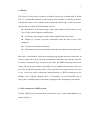
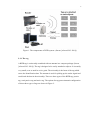
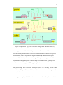
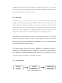
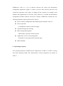
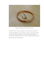
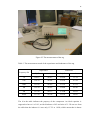
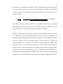
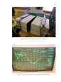
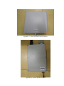
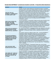
Wu Shen Wireless Power in Passive RFID Systems Bachelor’s Thesis Information Technology May 2010 DESCRIPTION Date of the bachelor's thesis 10th May, 2010 Author(s) Degree programme and option Wu Shen Information Technology Name of the bachelor's thesis Wireless Power in Passive RFID Systems Abstract Radio-frequency Identification (RFID) technology has many applications in various fields. Compared to a traditional Auto-ID system, the RFID technology has many advantages. Firstly, the identification of tags is more accurate and the distance is more flexible. Secondly, the maximum memory capacity of RFID tags can be several megabytes which is much more than that of the traditional Auto-ID’s. Thirdly, RFID has better performance in anti-pollution, because the data is saved in a chip wrapped by the tag. Finally, RFID tag is rewritable. We can add, modify and delete the data stored in the tag repeatedly. There are three types of RFID tags: passive tag, semi-passive tag, and active tag. Since there are no batteries in the passive tag, it has to get power from the reader to drive the chip inside. How is the power transported from readers to tags? How does the tag turn the high frequency AC to DC? How does the tag use this power to send signals back? These are the questions I concentrated on in this thesis. Finding out the ansewers to these questions can help users to implement a RFID system. Subject headings, (keywords) RFID, wireless power, passive tag, radio frequency Pages Language URN URN:NBN:fi:mamk-opinn2010A 53 pages English 8586 Remarks, notes on appendices Tutor Osmo Ojamies Employer of the bachelor's thesis ACKNOWLEDGEMENT At first of all, I would like to express my greatest appreciation to my parents. You always support me no matter what happens. I could get nothing without you. I will love you forever. Then, I would like to thank my tutor Mr Osmo Ojamies. Thank you for conducting me to complete the final thesis and helping me do the experiments. I did learn a lot from you. It’s my honor to meet you. Thirdly, I want to thank my mental tutor Mr Matti Koivisto and all the other teachers who have taught me in the Mikkeli University of Applied Sciences. Thanks for your help in my study and life in Finland. I can see the kindness of Finnish people from you. Fourthly, I want to thank my teachers in the Beijing University of Technology. Thank you for helping me when I was in the campus and giving me the chance to study in Finland. Last but not least, I would like to give my appreciation to my friend, Miss ZengZhen. Thank you for helping me search documents, and most importantly, encouraging me whenever I feel frustrated and lonely. CONTENTS 1 INTRODUCTION .................................................................................................... 1 2 OVERVIEW ............................................................................................................. 2 2.1 What is RFID..................................................................................................... 2 2.2 History ............................................................................................................... 3 2.3 The components of RFID system ...................................................................... 3 2.3.1 The tag ..................................................................................................... 4 2.3.2 The reader ................................................................................................ 6 2.3.3 The middleware ....................................................................................... 6 2.4 Operating frequency .......................................................................................... 7 2.5 RFID standards .................................................................................................. 9 2.5.1 ISO standards .......................................................................................... 9 2.5.2 EPC standards ....................................................................................... 10 3 WORKING PRINCIPLE OF RFID ....................................................................... 12 3.1 Propagation of electromagnetic wave ............................................................. 12 3.2 Coupling .......................................................................................................... 16 3.2.1 Backscatter coupling ............................................................................. 16 3.2.2 Inductive coupling ................................................................................. 17 3.2.3 Capacitive coupling ............................................................................... 19 3.3 Resonant energy transfer ................................................................................. 19 3.4 AC to DC ......................................................................................................... 20 3.5 Modulation method ......................................................................................... 23 3.5.1 Amplitude-shift keying .......................................................................... 24 3.5.2 Frequency-shift keying .......................................................................... 26 3.5.3 Phase-shift keying ................................................................................. 27 3.6 Encoding.......................................................................................................... 28 3.6.1 Types of encoding ................................................................................. 29 3.6.2 Pulse-interval encoding ......................................................................... 30 4 EXPERIMENTS .................................................................................................... 32 4.1 One-bit tag experiment .................................................................................... 32 4.1.1 The aim of the experiment..................................................................... 32 4.1.2 The equipment of the experiment .......................................................... 33 4.1.3 The process of the experiment............................................................... 34 4.1.4 The results of the experiment ................................................................ 39 4.2 Low frequency RFID energy transfer ............................................................. 39 4.2.1 The aim of the experiment..................................................................... 39 4.2.2 The equipment of the experiment .......................................................... 40 4.2.3 The process of the experiment............................................................... 40 4.2.4 The results of the experiment ................................................................ 43 4.3 The ultra high frequency RFID energy transfer .............................................. 44 4.3.1 The aim of the experiment..................................................................... 44 4.3.2 The equipment of the experiment .......................................................... 44 4.3.3 The process of the experiment............................................................... 44 4.3.4 The results of the experiment ................................................................ 48 5 CONCLUSION AND FUTURE DEVLOPMENT ................................................ 48 5.1 Conclusion ....................................................................................................... 48 5.2 My opinion and future development ............................................................... 49 REFERENCES ............................................................................................................. 51 LIST OF FIGURES AND TABLES Figure 1. The components of RFID system ................................................................... 4 Figure 2. Options for Tag Power/Transmit Configuration ............................................. 5 Figure 3. RFID Middleware ........................................................................................... 6 Table 1. RFID operating frequencies and associated characteristics ............................. 8 Figure 4. Transmission line terminated with Z0 ........................................................... 14 Figure 5. Transmission line terminated with short, open ............................................. 15 Figure 6. Transmission line terminated with a resistance other than the characteristic impedance..................................................................................................................... 16 Figure 7. Elements of simple backscatter modulation ................................................. 17 Figure 8. Inductive coupling power supply .................................................................. 18 Figure 9. Resonant circuit ............................................................................................ 20 Figure 10. Simple rectifier circuit ................................................................................ 21 Figure 11. Diode’s current-voltage characteristic ........................................................ 22 Figure 12. The result of a sine wave passing through a diode ..................................... 22 Figure 13. The result of sinusoidal pulses passing by a capacitor ............................... 23 Figure 14. Digital modulation method ......................................................................... 24 Figure 15. Amplitude-shift keying ............................................................................... 25 Figure 16. The spectrum of ASK.................................................................................. 26 Figure 17. Frequency-shift keying ............................................................................... 27 Figure 18. Phase-shift keying ....................................................................................... 28 Table 2. Common encoding method ............................................................................ 29 Figure 19. The waveforms of common encoding methods .......................................... 30 Figure 20. Pulse-interval coding symbols .................................................................... 31 Figure 21. The duration restrictions of PIE data-0 and data-1 ..................................... 31 Figure 22. The spectrum of PIE and OOK ................................................................... 32 Figure 23. The antennas ............................................................................................... 34 Figure 24. The components inside the one-bit tag ....................................................... 35 Figure 25. The measurement of the tag ........................................................................ 36 Table 3. The measurement result of the capacitance and inductance of the tag........... 36 Figure 26. The network analyzer connected antennas ................................................. 38 Figure 27. The spectrum of the receiving antenna without the tag .............................. 38 Figure 28. The spectrum of the receiving antenna with the tag ................................... 39 Figure 29. The antenna approaching the reader ........................................................... 41 Figure 30. The waveform of the LF RFID signal when the antenna was near the reader ...................................................................................................................................... 42 Figure 31. The waveform of the signal when the antenna was far from the reader ..... 43 Figure 32. The UHF antenna connected with the spectrum analyzer .......................... 45 Figure 33. The spectrum of the UHF signal ................................................................. 46 Figure 34. The carrier ................................................................................................... 47 Figure 35. The upper sideband ..................................................................................... 47 1 1 INTRODUCTION Radio-frequency Identification (RFID) technology has many applications in various fields. Mario Cardullo's U.S. Patent 3,713,148 in 1973 was the first true ancestor of modern RFID: a passive radio transponder with memory (Radio-frequency Identification, [referred 26.3.2010]). Since then, the application of RFID developed rapidly. Animal identification is one of the oldest uses of the RFID technology. By injecting an IC chip which is about the size of a large grain of rice into animals’ skin, we can easily identify it. This is very useful in the return of lost pets. RFID also contributes a lot to the supply chain management. With its help, we can improve the efficiency of inventory tracking and management. In an academic study performed at Wal-Mart, RFID reduced Out-of-Stocks by 30 percent for products selling between 0.1 and 15 units a day (Radio-frequency Identification, [referred 26.3.2010]). So now, many big companies, including Wal-Mart, require their suppliers to attach RFID labels to all shipments. Recently, the uses of RFID have become more and more diverse. For example: it can be used in a public transportation tolling system, in libraries to track books, even in mobile phones to make payments. Similarly with the development of technology, the growth of the RFID market has been dramatic as well. The global sales of the RFID system were approximately 900 million USD in the year 2000 (Finkenzeller 2003, 1). This is quite little compared to what it is now. A new market data report released by ABI Research predicts the overall RFID market to reach 5.35 billion USD this year, a glimmer of optimism after the economic slide required the firms to adjust their RFID forecasts downward for 2009 and 2010 (Sara Pearson Specter [referred 26.3.2010]). Compared to a traditional Auto-ID system, the RFID technology has many advantages. Firstly, the identification of tags is more accurate and the distance is more flexible. Secondly, the maximum memory capacity of RFID tags can be several megabytes 2 which is much more than that of the traditional Auto-ID’s. Thirdly, RFID has better performance in anti-pollution, because the data is saved in a chip wrapped by the tag. Finally, RFID tag is rewritable. We can add, modify and delete the data stored in the tag repeatedly. There are three types of RFID tags: passive tag, semi-passive tag, and active tag. Since there are no batteries in the passive tag, it has to get power from the reader to drive the chip inside. How is the power transported from readers to tags? How does the tag turn the high frequency AC to DC? How does the tag use this power to send signals back? These are the questions I concentrated on in this thesis. Finding out the answers to these questions can help users to implement a RFID system. The structure of the thesis is as follows: In Chapter 2, I will give an overview about the RFID technology, describing its history and components. In Chapter 3, I will introduce the working principle of passive RFID tags and RFID communication process. In Chapter 4, I will show how I did the experiments and what results I received eventually, as well as the analysis of the results. In Chapter 5, I will draw the conclusions based on my work, and discuss the problems and further research as well. 2 OVERVIEW 2.1 What is RFID Radio-frequency identification (RFID) is the use of an object (typically referred to as an RFID tag) applied to or incorporated into a product, animal, or person for the purpose of identification and tracking using radio waves (Radio-frequency Identification, [referred 26.3.2010]). 3 2.2 History The history of using radio frequency to identify objects can be dated back to World War Ⅱ, a transponder attached on the aircraft to show whether it is friendly or hostile. Though this seems to have nothing to do with modern RFID tags, it does have some features that are related to RFID (Dobkin 2008, 9): Identification of an object using a radio signal without visual contact or clear line of sight: radio-frequency identification An ID space big enough to allow unique identification of the object Linkage to a sensor to provide information about the state of the object identified Location of each object identified Transmission of relevant information from the interrogator to the transponder Since then, scientists have focused on making the tag cheaper and more functional. In order to achieve these, they removed the transmitter and battery from the tag. After the invention of integrated logic circuitry in the 1960s, the RFID technology came to its spring. The tag became smaller and smaller, but its capability became more and more powerful. Around the beginning of the 1970s, tags based on resonant circuit were used in one of the first major commercial implementations of RFID technology by the Schlage Lock Company (Dobkin 2008, 13). Nowadays, we can find RFID tags in many places, including libraries, hospitals, shopping malls, and highway toll stations. 2.3 The components of RFID system Usually, a RFID system contains three components: tags, a reader and middleware, as shown in Figure 1. 4 Figure 1. The components of RFID system--(Sorour [referred 29.3.2010]) 2.3.1 The tag A RFID tag is a microchip combined with an antenna in a compact package (Sorour [referred 29.3.2010]). The tag is designed to be easily attached to objects. It is usually very small, even as small as a rice grain. The microchip is the heart of the tag which stores the identification data. The antenna is used for picking up the reader signal and sends back the data in the microchip. There are three types of the RFID tag: passive tag, semi-passive tag and active tag. The options for tag power/transmit configuration of these three types of tags are shown in Figure 2. 5 Figure 2. Options for Tag Power/Transmit Configuration--(Dobkin 2008, 35) Passive tags contain neither electrical power nor a radio transmitter. The power to drive the circuitry and microchip is received from rectification of the received power from the reader, and the tag sends the signal back through a backscattered signal. Because of functioning without batteries, tags of this type are cheap, small and have a long life time. Though they have a limited range of communication, typically a few feet, they are the most popular RFID tags in applications. Semi-passive tags have their own battery to power the circuitry, but no radio transmitters. They still use backscattered communication for tag-to-reader communication. Active tags are equipped with batteries and antennas. Therefore, they can initiate 6 communication and work in a large range up to hundreds of feet. They can even have sensors inside. However, these types of tag are expensive and large. Thus, they don’t have as many applications as passive tags do. 2.3.2 The reader A RFID reader is, at heart, a radio transceiver: a transmitter and receiver that work together to communicate with the tags (Dobkin 2008, 103). The reader has its own antenna and power supply, and usually it is connected to a computer or microcomputer which can manage the data read from the tag. Communication between readers and tags can be with or without line-of-sight propagation. We use special protocols to control the communication. One reader can support one or multiple protocols. RFID readers can be divided into two classes: read-only and read/write. The read-only reader usually operates with passive tags. It can do nothing except read out the data in the tag. Read/write reader can modify the information in the tag, in the case that the tag is equipped with re-writable memory. The reader can either be fixed in a place or handheld, even embedded in PDA or a mobile phone. Some handheld readers resemble a bar code scanner to make them have more functions. Sometimes, handheld readers support 802.11 protocols, so that they are able to send the information to a database wirelessly. 2.3.3 The middleware Figure 3. RFID Middleware 7 Middleware refers to a set of software between the reader and information management application (Figure 3) which is used to deal with the data flow and control the operation of the reader. It includes all the software, for example, local database and Application-Level Events (ALE). However, it excludes the information management terminal software and device software. Middleware should have the following functions (Sorour [referred 29.3.2010]): Device control, configuration and monitoring for hundreds of devices Device operation - Command the reader to read/write tag(s) Tag data filtering and cleansing Data routing and integration - Which data is passed to which recipient Application services event management - Respond to events generated by business apps Data translation 2.4 Operating frequency The operating frequency of RFID can be ranged from 30 kHz to 30 GHZ, covering four main frequency bands. The characteristics of these frequencies are shown in Table 1: 8 Table 1. RFID operating frequencies and associated characteristics--(IEE 2005 [referred 30.3.2010]) As we can see from the table, the high frequency wave has a higher data rate and larger read range than the low frequency one. However, there is one thing which is not shown in the table, the low frequency wave can penetrate walls but the high frequency wave cannot. So if we are going to design an indoor RFID system, this factor must be taken into consideration. RFID systems based on LF and HF frequencies make use of near field communication 9 and the physical property of inductive coupling from a magnetic field. On the other hand, RFID systems based on UHF and higher frequencies use far field communication and the physical property of backscattering or 'reflected' power (Ward & Kranenburg, [referred 30.3.2010]). Another important issue is that different countries have different restrictions in the frequency band. For example, in order to prevent collisions, the future Licensing Act for Inductive Radio System in Europe, 220 ZV 122, will define a protected zone of between 70 and 119 kHz, which will no longer be allocated to RFID system (Finkenzeller 2003, 163). 2.5 RFID standards Standards play a significant role in the RFID industry, because they control the process of communication. There are existing and proposed RFID standards that deal with the air interface protocol (the way tags and readers communicate), data content (the way data is organized or formatted), conformance (ways to test that products meet the standard), and applications (how standards are used on shipping labels, for example).(A Summary of RFID Standards, [referred 2.4.2010]) The International Organization for Standardization and the Electronic Product Code are the two organizations in the world working on the RFID Standards. 2.5.1 ISO standards The International Organization for Standardization (ISO) has addressed many standards concerning with RFID. Perhaps the most important one is ISO-18000 series, which is for item management and automatic identification. This set of standards defines the parameter of the air interface, including the bit rate and the way of modulation and coding, as well as the collision arbitration. For example, ISO-18006 10 type A sets that we shall use pulse interval encoding at 33 kbps for the forward link and bi-phase space FM0 encoding at 40 or 160 kbps for the return link. Aloha-based mechanism shall be used for collision arbitration. Totally, there are seven parts in ISO-18000, each of which defines the air interface for a certain range of frequency: 18000–1: Generic parameters for air interfaces for globally accepted frequencies 18000–2: Air interface for 135 KHz 18000–3: Air interface for 13.56 MHz 18000–4: Air interface for 2.45 GHz 18000–5: Air interface for 5.8 GHz 18000–6: Air interface for 860 MHz to 930 MHz 18000–7: Air interface at 433.92 MHz Besides this, the ISO has created standards for tracking cattle with the RFID. ISO 11784 defines how data is structured on the tag. ISO 11785 defines the air interface protocol. ISO has created a standard for the air interface protocol for RFID tags used in payment systems and contactless smart cards (ISO 14443) and in vicinity cards (ISO 15693). It also has established standards for testing the conformance of RFID tags and readers to a standard (ISO 18047), and for testing the performance of RFID tags and readers (ISO 18046). (A Summary of RFID Standards, [referred 2.4.2010]) 2.5.2 EPC standards The Electronic Product Code originally divides RFID tags into 4 classes (Tag Class Definitions [referred 3.4.2010]): Class-1: Identity Tags Passive-backscatter tags with the following minimum features: An electronic product code (EPC) identifier A tag identifier (Tag ID) A function that renders a tag permanently non-responsive Optional decommissioning or recommissioning of the Tag 11 Optional password-protected access control Optional user memory Class-2: Higher-Functionality Tags Passive tags with the following anticipated features above and beyond those of Class-1 tags: An extended tag ID Extended user memory Authenticated access control Additional features (TBD) as will be defined in the Class-2 specification. Class-3: Battery-Assisted Passive Tags (called Semi-Passive Tags in UHF Gen2) Passive Tags with the following anticipated features above and beyond those of Class-2 Tags: A power source that may supply power to the tag and/or to its sensors Sensors with optional data logging Class-4: Active Tags Active Tags with the following anticipated features: An electronic product code (EPC) identifier An extended tag ID Authenticated access control A power source Communications via an autonomous transmitter Optional user memory Optional sensors with or without data logging Because I focus on the Class 1 tags in this thesis, I will introduce the Class-1 Gen-2 UHF RFID protocols in detail. This protocol is designed for communications at 860 MHz - 960 MHz. The bit rate shall be 26.7 kbps - 128 kbps in both the reader to tag and tag to reader communication. Interrogators shall use DSB-ASK, SSB-ASK, or PR-ASK modulation 12 and tags shall be able to demodulate all these three modulation types. Data shall be encoded by pulse interval encoding. Tags communicate information by backscatter modulating the amplitude and/or phase of the RF carrier (UHF Class 1 Gen 2 Standard v. 1.2.0 [referred 3.4.2010]). Communication between the interrogators and the tags performs in half-duplex way, which means that readers and tags shall not talk simultaneously. 3 WORKING PRINCIPLE OF RFID 3.1 Propagation of electromagnetic wave Electromagnetic wave carries RFID signals. So first of all, I will introduce some basic knowledge about it. An electromagnetic field can be viewed as the combination of an electric field and a magnetic field which oscillates in phase perpendicular to each other and perpendicular to the direction of energy propagation. The electric field is produced by stationary charges, and the magnetic field is produced by moving charges (currents). These two are often described as the sources of the field (Electromagnetic Field [referred 7.4.2010]) and also the electric field and the magnetic field interact with each other. This kind of interaction is very complicated. Simply speaking, an altering electric field produces a magnetic field, and so does an altering magnetic field. An electromagnetic field propagates in wavelike manner at the speed of 3×10⁸ m/s in the vacuum of space, so we usually call it an electromagnetic wave. An electromagnetic wave will produce an electric current through any conductor which it passes. This is where the passive RFID tags get their energy from. Radio frequency wave is a type of electromagnetic wave, whose frequency is below 300 GHz and above 3 kHz. By systematically changing the amplitude, frequency or 13 phase of the wave, we can insert information into it. When the wave hits an electric conductor, it will induce a varying current, which can be detected and transformed into an image, sound or other meaningful signals. When not propagating in free space, electromagnetic waves behave like light. Actually, light is a kind of electromagnetic wave. Reflection, refraction and diffraction often occur during the propagation. A conductive medium is like a mirror. When electromagnetic waves meet it, it will reflect the waves back and change their phase as well. Meanwhile, some waves can pass through the ―mirror‖ but propagate in another direction, which is called refraction. Diffraction occurs when waves bend around an obstacle. Reflection is crucial to the RFID system. The reflection in the RFID system works like in a transmission line. A transmission line is a type of cable whose length is longer than or approximately equals to the wavelength of the RF signal passing through it. Each transmission line has its own characteristic impedance Z0 whose value depends only on the property of the line. When a transmission line is terminated with load Z0, all the incident power will be absorbed by the load. Therefore, there will be no energy reflected back, so the envelope of the RF signals will remain constant. For reflection, a transmission line terminated in Z0 behaves like an infinite transmission line, which is shown in Figure 4. 14 Figure 4. Transmission line terminated with Z0--(Network Analyzer Basics [referred 16.4.2010]) When a transmission line is terminated with open or short circuit, no energy will be absorbed and all the power will be reflected back. The reflected wave and the incident wave will be identical in amplitude, but out-of-phase (180°) for short circuit and in-phase (0°) for open circuit. In both case, the reflected and incident waves will travel in opposite direction, and a standing-wave pattern will be set up on the transmission line. The valleys will be zero and peaks twice the magnitude of incident wave. This is shown in Figure 5. an 15 Figure 5. Transmission line terminated with short, open--(Network Analyzer Basics [referred 16.4.2010]) When a transmission line is terminated with a resistance other than the characteristic impedance, some power will be absorbed by the load while the rest will be reflected back. The reflected wave will also travel in the opposite direction, but its magnitude will be no longer the same with the incident wave and its phase will alter to the distance along the transmission line from the load. A standing-wave pattern will still be set up on the transmission line, but its valley will be above zero and peaks below twice the magnitude of the incident wave. This is shown in Figure 6. 16 Figure 6. Transmission line terminated with a resistance other than the characteristic impedance--(Network Analyzer Basics [referred 16.4.2010]) 3.2 Coupling 3.2.1 Backscatter coupling Passive RFID tags working on 868MHz and 915MHz use backscatter to send signals back to the reader. In physics, backscatter (or backscattering) is the reflection of waves, particles, or signals back to the direction they came (Backscatter [referred 17.4.2010]). This kind of reflection is a little different from the mirror reflection. It is diffuse reflection, because the reflected lights or signals travel not only in the exact opposite direction, but also other directions. 17 Figure 7. Elements of simple backscatter modulation--(Dobkin 2008, 211) As we can see from Figure 7, there are three states of the tag antenna: normal operation, open circuit, and short circuit. In the normal operation, the IC is perfectly matched to the antenna like a transmission line terminated with load Z0. In this case, some power is backscattered. In the open circuit, because there is no current passing through the circuit, nothing is backscattered. In the short circuit, since the current meets little impedance, it reaches its maximum. Consequently, a large amount of power is scattered back. In practice, we use electronic switches, transistors, to control the circuitry. The transistors gate pole is connected to the output of the IC in the tag. Once the IC gets its power from the antenna, it will control the transistor to switch on and off corresponding to the data in its memory, and indirectly, it can control the backscatter radiate power. In this way, we can amplitude modulate the signals sent back to the reader. In the reader, we use a directional coupler to transfer the signals to the receiver input of a reader. 3.2.2 Inductive coupling In electrical engineering, two conductors are referred to as inductively coupled or magnetically coupled when they are configured so that a change in the current flow through one wire induces a voltage across the ends of the other wire 18 through electromagnetic induction (Inductive coupling [referred 18.4.2010]). Some RFID systems, especially those using below 135kHz or 13.56MHz frequency band, use inductive coupling to exchange information between the tags and readers antennas, because their wavelength is much larger than the distance between the tags and readers. The inductive coupling in the RFID system works like a transformer. The tags and readers have coil antennas. The reader coil can generate a strong electromagnetic field. Once a tag enters this field, it can produce a voltage in the tag’s coil, just like the transformer’s primary winding generating a voltage in the secondary winding (Figure 8). This voltage serves as the power supply for the IC in the tag. Then the IC controls the transistor to shunt the tag coil. The RF link behaves essentially as a transformer, when the secondary winding is momentarily shunted, the primary winding experiments a momentary voltage drop. By repeatedly shunting the tag coil through the transistor, the tag can cause slight fluctuations in the reader’s RF carrier amplitude. (microIDTM 125kHz RFID System Design Guide 1998, 2) Though the fluctuations seem tiny, 100mV riding on a 100V sine wave for example, they are already huge enough for the reader to detect them. In this way, we are able to send meaningful signals back to the reader. Figure 8. Inductive coupling power supply--(Finkenzeller 2003, 42) 19 3.2.3 Capacitive coupling In electronics, capacitive coupling is the transfer of energy within an electrical network by means of the capacitance between circuit nodes (Capacitive coupling [referred 19.4.2010]). Capacitive coupling tags are cheaper than the inductive coupling ones, because instead of the coil, they use a small quantity of silicon to accomplish the same function. Capacitive coupling involves the reader emitting a propagating electromagnetic wave. When this wave impinges on a tag, the chip will modify the antenna radar cross section in such a way that the reflected signal containing the information on the chip can be detected by the reader. This is the primary mode of operation at UHF and in the microwave region. (Physics of RFID [referred 19.4.2010]) 3.3 Resonant energy transfer One-bit passive RFID tags are working based on a resonant circuit. The resonant circuit consists of an inductance and a capacitance series connected with each other. The resonant circuit has its own resonant frequency only determined by the inductance and capacitance (Formula 3.4.1). f = 2π 1 LC (Formula 3.3.1) When this frequency is reached, the circuit’s impedance will become minimum. Thus, a large current flows through transponder, resulting in an abrupt drop in the voltage (Figure 9). 20 Figure 9. Resonant circuit—(Dobkin 2008, 12) A high frequency oscillating current flows through the reader, producing a high frequency magnetic field. According to Faraday’s law of induction, once the tag coil enters this field, it can pick up most of the energy and generate an induced current. Since both the coil and capacitance have impedance, this current will produce a voltage over the circuit. The reader can keep sweeping a range of frequencies including the resonant frequency. When encountering with it, the reader can detect the drop in voltage. In this way, one bit is sent to the reader. Since the tag can carry multiple resonances of various frequencies, the system can have a large ID space. 3.4 AC to DC The energy an antenna picks up from the electromagnetic field is high frequency altering-current (AC) power which cannot directly drive the microchip in the tag. Therefore, we have to turn it to direct-current power (DC). This kind of power should have magnitude from 1 to 3 V, and both the magnitude and the direction of the current should seldom change with time. In order to achieve this, we use a rectifier circuit. 21 Figure 10. Simple rectifier circuit—(Dobkin 2008, 19) Figure 10 shows a simple rectifier circuit. Two basic components of this circuit are the diode and capacitor. A diode can only pass currents in one direction. It has a very high impedance in the opposite direction. We can see its current-voltage characteristics in Figure 11. In the forward direction, current increases rapidly after it reaches a certain turn-on voltage. In the reverse direction, only small leakage current is allowed till its reaches the breakdown voltage which can damage the diode seriously. Based on these features, we can turn the sine wave into sinusoidal pulses (Figure 12). 22 Figure 11. Diode’s current-voltage characteristic Figure 12. The result of a sine wave passing through a diode The next step is to change these sinusoidal pulses into DC current. All we need is a capacitor. A capacitor can temporarily store electric charges and its charging speed is much faster than the discharging speed. Thus, when the sine wave is at its positive half, the capacitor will charge itself. When the sine wave reaches its negative half, the capacitor begins to discharge. Then, the sine wave will reach its positive half again, so the capacitor will charge again. Because the speed of discharging is very slow, the voltage only drops a little bit before it rises again. In this way, we can keep the voltage roughly constant (Figure 13). 23 Figure 13. The result of sinusoidal pulses passing by a capacitor 3.5 Modulation method Air can only transmit analog signals. Therefore, we need to modulate the signals before transmission. Modulation is the process of varying one or more properties of a high frequency carrier signal corresponding to a meaningful low frequency signal (modulating signal), in order to make it suitable for the medium. A digital signal can modulate the amplitude, frequency, or phase of a sinusoidal carrier wave (Carlson, 512). According to which kind of properties is altered, we divide the digital modulation into three basic types: amplitude-shift keying (ASK), frequency-shift keying (FSK) and phase-shift keying. The waveforms of these modulation methods are shown in Figure 14. 24 Figure 14. Digital modulation method—(Juutilainen, 2010) 3.5.1 Amplitude-shift keying ASK alters carriers’ amplitude in accordance with the data sequence. This kind of modulation is widely used in the RFID tags, because it is easy to implement. The simplest and most common form of ASK operates as a switch, using the presence of a carrier wave to indicate a binary one and its absence to indicate a binary zero. This type of modulation is called on-off keying (OOK), and it is used at radio frequencies to transmit Morse code (Amplitude-shift keying [referred 24.4.2010]). For example, we can use amplitude Ac stands for bit ―1‖ and 0 for bit ―0‖. We assume that the frequency of the carrier is fc. Then, we can figure out the formula of ASK: s t = Ac sint 2πfc t for bit "1" 0 for bit "0" The time domain of ASK is illustrated in Figure 15. (Formula 3.5.1.1) 25 Figure 15. Amplitude-shift keying—(Juutilainen, 2010) Amplitude modulation results in a shift of the spectrum in frequency domain. The spectrum of signals modulated by ASK consists of three parts: the carrier, the upper sideband, and the lower sideband. The carrier locates in the center of the spectrum and two sidebands locate symmetrically above and below the center. The frequency difference between the center and the sidebands indicates the frequency of the modulating signal. For example, if the frequency of the carrier is fc and that of the modulating signal is f0, then the sidebands locate in fc+f0 and fc-f0. The spectrum is shown in Figure 16. 26 Figure 16. The spectrum of ASK 3.5.2 Frequency-shift keying FSK changes the frequency of the carrier corresponding to the data sequence. The carrier keeps its amplitude and phase constant, but it has different frequency for different bits. The formula of FSK is s t = Ac sin 2πfc1 t Ac sin 2πfc2 t 𝑓𝑜𝑟 𝑏𝑖𝑡 "1" 𝑓𝑜𝑟 𝑏𝑖𝑡 "0" (Formula 3.5.2.1) Ac is the amplitude of the carrier and fc1 and fc2 are two different frequencies. The time domain of FSK is illustrated in Figure 17. 27 Figure 17. Frequency-shift keying—(Juutilainen, 2010) 3.5.3 Phase-shift keying PSK varies the phase of the carrier in accordance with the data sequence. The difference between the phases can be 180°or any other degree. The smaller the difference is, the more symbol states we have which means higher efficiency, but if the difference is too small, it will be difficult to distinguish them from each other, so we need to find a trade-off. The following formula and Figure 18 shows a very simple PSK. s t = Ac sin 2πfc t 𝑓𝑜𝑟 𝑏𝑖𝑡 "1" Ac sin 2πfc t + π 𝑓𝑜𝑟 𝑏𝑖𝑡 "0" (Formula 3.5.3.1) 28 Figure 18. Phase-shift keying—(Juutilainen, 2010) We usually don’t implement PSK solely, but it is combined with other modulation methods. For example, the quadrature amplitude modulation is a combination of ASK and PSK. It changes both the amplitude and phase of the carrier. It is very widely used in wireless communication, but not in the RFID tags, because it is very complicated to implement. 3.6 Encoding There is a drawback of OOK. As I mentioned before, ASK uses nothing to represent bit ―0‖. This is unacceptable in the passive RFID system, since the power of the passive tags comes from the reader. If the reader is sending a signal containing a long string of ―0‖, the tag will receive no power during that time, which may cause the microchip in the tag to be power-off. One of the solutions to this problem is to encode the data. 29 3.6.1 Types of encoding There are several ways to encode the data. Each has its own merits as well as drawbacks, and its own suitable application. The most common encoding methods are shown in Table 2 and their waveforms are illustrated in Figure 19. Table 2. Common encoding methods—(Communication method/line codes [referred 24.4.2010]) Non-return to zero level. This is the standard positive logic signal format used in digital circuits. NRZ-L 1 forces a high level 0 forces a low level Non-return to zero mark. NRZ-M 1 forces a transition 0 does nothing Non-return to zero space. NRZ-S 1 does nothing 0 forces a transition Return to zero. RZ 1 goes high for half the bit period 0 does nothing Manchester. Two consecutive bits of the same type force a transition at the beginning of a bit period. Biphase-L 1 forces a negative transition in the middle of the bit 0 forces a positive transition in the middle of the bit There is always a transition at the beginning of a bit period. 1 forces a Biphase-M transition in the middle of the bit. 0 does nothing. 30 There is always a transition at the beginning of a bit period. 1 does Biphase-S nothing 0 forces a transition in the middle of the bit. There is always a transition in the middle of a bit period. Differential 1 does nothing Manchester 0 forces a transition at the beginning of the bit The positive and negative pulses alternate. Bipolar 1 forces a positive or negative pulse for half the bit period 0 does nothing Figure 19. The waveforms of common encoding methods—(Communication method/line codes [referred 24.4.2010]) 3.6.2 Pulse-interval encoding Pulse-interval encoding is used in EPCglobal Class 1 Generation 2 standards. It can 31 solve the power problem caused by a long string of ―0‖s. PIE is usually implemented before the modulation. In PIE, a binary ―1‖ is coded as a short power-off pulse following a long full-power pulse, and a binary ―0‖ is coded as a shorter full-power interval with the same power of pulse (Dobkin 2008, 60). The symbols are illustrated in Figure 20. By encoding the data in this way, we can make sure that at least 50% of the maximum power is transferred to the tag, even though there is a long string of ―0‖s. The durations of off–time and on-time are restricted by the standards. The durations set by EPCglobal Class 1 Generation 2 are shown in Figure 21. Please notice that the Tari, which equals to the duration of data-0, is the reference time interval of reader-to-tag communication. As we can see from the figure, the duration of binary 0 is much shorter than that of binary 1. Thus, the data rate is related to the data: a stream of ―0‖s is transmitted more rapidly than a stream of ―1‖s. Figure 20. Pulse-interval coding symbols--(Dobkin 2008, 60) Figure 21. The duration restrictions of PIE data-0 and data-1—(EPC Class1 Gen 2) 32 PIE consumes more bandwidth compared to OOK for the same data rate. It also produces a strong narrow emission far from the carrier, as well as a higher average signal power far from the carrier (Dobkin 2008, 65). This is illustrated in Figure 22. Figure 22. The spectrum of PIE and OOK—(Doobkin 2008, 65) 4 EXPERIMENTS 4.1 One-bit tag experiment I firstly did an experiment with a one-bit tag. 4.1.1 The aim of the experiment One-bit tags are widely used in shops and supermarkets to protect goods from being stolen. This kind of tag is usually attached to the merchandise. If somebody wants to 33 bring it outside the shop without paying, the antennas at the gate will detect the tag and trigger the alarm. In this experiment, we firstly opened a one-bit tag to check its physical structure. Then, we simulated the situation that a tag passed through the antennas, in order to find out the working principle of this type of tag and what happens in the physical layer. 4.1.2 The equipment of the experiment The equipment of the experiment included the following: A one-bit passive RFID tag (Appendix 1) A set of antennas A LCR HiTester A network analyzer The one-bit passive tag was acquired from a shop. The antennas (Figure 23) were made by my tutor and me. We used some wires wrapped over two cartons to make the antennas. Although quite simple, these could perfectly simulate the real antennas in the shop. I used LCR HiTester to measure the capacitance and inductance of the tag, and a Network analyzer to observe the spectrum of the signal between two antennas. 34 Figure 23. The antennas 4.1.3 The process of the experiment At the first of all, I opened the tag to check its physical structure. Figure 24 shows the components inside the one-bit tag. As we can see from the picture, the structure was quite simple. There was no microchip in the tag. The circuitry only consisted of an inductor coil serially connected with a capacitor. This looked like the structure of resonant circuit as I mentioned in Chapter 3.4, so I supposed that the one-bit tag worked based on resonant wireless power transfer. 35 Figure 24. The components inside the one-bit tag Secondly, in order to verify my assumption, I used LCR HiTester to measure the capacitance and inductance so that I could figure out the resonant frequency (Figure 25). Since the frequency determines the value of capacitance and inductance, I measured them at different frequencies from 1 kHz to 4.5 MHZ (the maximum of the HiTester). The result is shown in Table 3. 36 Figure 25. The measurement of the tag Table 3. The measurement result of the capacitance and inductance of the tag Capacitance Frequency/Hz Inductance C/pF θ L/μ H θ 1k 120.87 -89.97° 2.9514 13.70° 10k 120.78 -89.98° 2.9543 67.58° 100k 121.08 -89.93° 2.9347 87.18° 1M 125.20 -89.95° 2.8668 89.46° 3M 127.42 -90.37° 2.7644 89.82° 4.5M 137.20 -90.18° 2.6235 90.05° The θ in the table indicates the property of the component. An ideal capacitor is supposed to have a θ of -90°, an ideal inductor of 90°and wire of 0°. We can see from the table that the inductor’s θ was only 13.70°at 1 kHz, which meant that it almost 37 worked like a wire rather than an inductor. Thus, I inferred that the tag could not work at a low frequency band. So I used the values measured at 4.5 MHz to calculate the resonant frequency. The calculation was based on Formula 3.3.1, and the process was shown as follows: f= 1 2π LC = 1 2 × 3.14 × 137.20 × 10−12 × 2.6235 × 10−6 = 8.39 MHz The resonant frequency was 8.39 MHz, so I should have measured the capacitance and inductance at that frequency, but the maximum frequency of the HiTester was only 4.5 MHz. Thus, I decided to use the measurements at 4.5 MHz. Finally, I used the network analyzer to check what would happen in the spectrum at 8.39 MHz when the tag passed through the antennas. One of the antennas was connected with the transmitter port of the network analyzer, and the other one with the receiver port (Figure 26). I set the start frequency of the spectrum to 7.2 MHz and terminal frequency to 9.2 MHz so as to put 8.39 MHz around the middle of the spectrum. We can see the spectrum when there is no tag between the antennas in Figure 27. Then, I put the tag between two antennas, which caused a big change in the spectrum. As we can see from Figure 28, there is a sharp burst, about 4 dB above the normal level, between 8.2 MHz and 8.4MHz. This can be considered as the signal that the tag sent to the reader. When the reader detected this signal, it triggered the alarm. 38 Figure 26. The network analyzer connected antennas Figure 27. The spectrum of the receiving antenna without the tag 39 Figure 28. The spectrum of the receiving antenna with the tag 4.1.4 The results of the experiment This experiment verified that one-bit tags used in the shop work based on resonant energy transfer. Their resonant frequency was between 8.2 MHz and 8.4 MHz. When a tag passed through the antennas, it would produce a burst at its resonant frequency which could trigger the alarm. 4.2 Low frequency RFID energy transfer This experiment is done with a low frequency RFID reader. 4.2.1 The aim of the experiment The low frequency (LF) RFID system refers to the RFID systems that operating below 300 kHz but above 30 kHz. This type of system is mainly used in animal identification, 40 car immobilizers, and the access control on doors. This experiment is targeted at measuring the operating frequency of a low frequency RFID system and how much energy the tag antennas can get from the reader. 4.2.2 The equipment of the experiment The equipments of the experiment included the following: An Indala Low frequency RFID reader (Appendix 2) A tag antenna A oscilloscope I used the RFID reader on the door as the measuring object. Though I didn’t know its operating frequency at first, I supposed it worked at LF band, as most of the access control readers are LF systems. It was very difficult to use the real tag antenna since it was too tiny, so I used a cable to replace it. I connected the cable’s positive and negative ends together to make a sing-turn coil antenna. The real antenna is similar to this but has more turns. The oscilloscope was used to show the waveform of the signal and measure its magnitude. 4.2.3 The process of the experiment Firstly, I connected the antenna to the CH1 of the oscilloscope. After that, I held the antenna and moved approaching the reader (Figure 29). The antenna was able to pick up the signal when it was about 5 centimeters away from the reader. I put the ―Autoset‖ button on the oscilloscope to make the image on the screen clear and stable. Then, I continued approaching the reader till the last few millimeters before the antenna could touch the reader. At this time, I could get the maximum power that the reader was sending to the tag. The waveform of the signal received from the antenna is shown in Figure 30. 41 Figure 29. The antenna approaching the reader 42 Figure 30. The waveform of the LF RFID signal when the antenna was near the reader As we can see from the figure, the signal that the antenna received was a sine wave without modulation. Its frequency was 125.007 kHz, which verified my supposition. The magnitude from peak to peak was 172 mV. This voltage, though fairly small, was supposed to be the largest the antenna could get. The magnitude was related to the distance between the antenna and the reader. When I moved the antenna a little further, the peak to peak magnitude was 168 mV, smaller than the former one (Figure 31). 43 Figure 31. The waveform of the signal when the antenna was far from the reader In the end, I tried to find what would happen to the waveform when the reader was transmitting signals, but failed, because the voltage difference was too tiny to be seen from the oscilloscope. 4.2.4 The results of the experiment The experiment verified that the RFID access control on the door was a LF system. Its working frequency was 125.007 kHz. The signal generated by the reader was not modulated when there were no tags nearby. The power that the reader sent to the tag depended on the distance between them. The maximum power the antenna picking up was 172 mV. This was very small because the antenna was a single-turn coil antenna. In real tags, there are more turns in the antenna, so the magnitude can be many times of the measuring value. 44 4.3 The ultra high frequency RFID energy transfer This experiment is done with a high frequency RFID reader. 4.3.1 The aim of the experiment The ultra high frequency (UHF) RFID system works at frequencies from 300 MHz to 3 GHz. This type of system is widely used in supply chain management. Its antennas structure is different from that of LF RFID system, so the energy transition is different as well. This experiment was aimed to illustrate the spectrum of the UHF signal sent by the reader and measure how much power the antenna can pick up. I also expected to find the modulation type of the signal. 4.3.2 The equipment of the experiment The equipments of the experiment included the following: A Vilant UHF RFID reader and its antenna (Appendices 3-4) A UHF receive antenna A spectrum analyzer A computer installed with RFID software According to the user manual, the Vilant UHF RFID reader works at 865 MHz, so I selected it as the object. The RFID software can control the reader. The UHF antenna is used for picking up the signal and transmits it to the spectrum analyzer. Because of the frequency band limitation, I could not use the oscilloscope to observe the signal in time domain. Thus, I chose the spectrum analyzer to observe the signal in frequency domain, which could also be used for measuring the power. 4.3.3 The process of the experiment At first, I connected the RFID reader to the computer through serial port. Then, I used 45 the software to make the reader begin to detect the tags. After that, I used the antenna to pick up the signal (Figure 32). The antenna was connected to the spectrum analyzer, so that I could see the spectrum of the signal which is shown in Figure 33. Figure 32. The UHF antenna connected with the spectrum analyzer 46 Carrier Sidebands Figure 33. The spectrum of the UHF signal As we can see from the figure, the spectrum was quite clear. There was a carrier in the middle and two sidebands symmetrically around it. This was a typical spectrum of ASK. Therefore, I inferred that the reader modulated the signal by ASK. The carrier was located at 865 MHz. The frequency difference between the carrier and sidebands was 6 MHz which indicated that the modulating signal’s frequency was 6 MHz. The carrier was about 70 dB above the noise level (Figure 34). It was not very stable because of interference and noise. The sidebands were 10 dB above the noise level (Figure 35). The spectrum analyzer can only show the decibel, so I could not know the absolute value of the carrier and sidebands. In order to know the power received by the tag, the power scale of the analyzer should be calibrated, and the measurement should be made by using an antenna, which is similar to the antenna in the tag. 47 Figure 34. The carrier Figure 35. The upper sideband 48 4.3.4 The results of the experiment This experiment showed that the UHF RFID reader generated signals modulated by ASK. When the tag picked up the signal, it needed to demodulate the signal at first. I also measured the power of the carrier and sidebands which were separately 70 dB and 10 dB above the noise level. The system worked at 865 MHz which was the carrier’s frequency. The original signal was at 6 MHz. 5 CONCLUSION AND FUTURE DEVLOPMENT 5.1 Conclusion These three experiments revealed the working principles of three kinds of RFID systems. They have similarities as well as differences. Especially, I concentrated on the part of wireless power transfer. Basically, the wireless power transfers in these three types of systems all work based on the Faraday’s law of induction. All of them transmit the energy in the form of electromagnetic field. All the tags have coil antennas in order to pick up the energy. When the antenna enters an electromagnetic field, the field can produce a current in the antenna which is the power source of the tag. In the UHF tags also dipole antennas are possible, because the wavelength is smaller. The minimum sizes of efficient dipole antennas are from about 0.1 to 0.5 wavelengths. At 865 MHz this means about 3 to 17 cm. The differences among these three kinds of RFID systems are obvious. Firstly, the LF and UHF passive RFID tags both have microchips inside. Thus, DC power is needed to drive the chip, so they must convert the high frequency AC power to DC, and rectify circuitries are applied. However, the one-bit RFID tag contains no microchips. 49 It only has an inductor and a capacitor which are serially connected with each other. Therefore, it can use the AC power directly. This simplifies its structure but limits the functions as well: what it can send is only one bit, so this kind of tag does not have diverse applications. Secondly, the signals generated by the LF RFID reader and the UHF one are different. The LF RFID reader produces a simple sine wave which is not modulated while the UHF reader modulates the signal by ASK before sending it. Thus, when the UHF tag receives the signal, it must firstly demodulate it, and then, extract the DC component to drive the microchip. Finally, the UHF reader can transmit the power to a very long distance, even several meters away. However, the LF reader can only transmit the power as long as 10 centimeters. The reason for this is the use of near field (inductive) coupling instead of far-field communication in LF reader. In LF the antennas are very small compared to the wavelength. This makes them to be very inefficient far-field radiators. Another reason is security. We all hope that a person can only open the door when he is near the door, rather than when he is still 10 meters away from the door. 5.2 My opinion and future development Through the experiments, I learnt the working principle of the RFID systems and what happened in the physical layer, both in time domain and frequency domain. I also figured out how the readers transmit energy to the tags. I have a thought that we can implement the working principle of wireless power in other applications. Since tags can get power from the reader, other electric stuff should also be able to get power from a wireless power source. If we are able to install a receiver in a mobile phone, it will charge by itself when entering a certain ―power supply‖ area. We can use the wireless power to replace the traditional wire power by installing a wireless power transmitter at home and a receiver to every electric product. Actually, wireless power has already been implemented in some fields of our life. The electric toothbrush is a good example. Because the head of the brush is often dipped 50 into water, it is unsafe to use wire power. Thus, the engineers use two coils to transmit the power. It works based on inductive coupling. The motor in the head can power from the batteries at the end wirelessly, like a RFID tag getting power from its reader. However, there are many problems of this application. Firstly, the power that we can transmit now is very low, only about a few hundreds of milliwatts. This is enough for a motor in an electric toothbrush or a microchip in a RFID tag, but too low for a television set whose power is usually 100 watts. Of course, we can raise the voltage of the source, but if so, health problem will arise. A very strong electromagnetic field can do damage to a human brain. Therefore, we need to find a way to send the power safely. Secondly, in most cases, one wireless power source needs to supply several home appliances. If there are many objects that need power from the source, it is a big issue that the voltage will be unstable. This may affect the performance of every appliance. We need to keep the voltage stable even when there are lots of devices that need power. The next issue is about the efficiency. We don’t like to waste power, so we should figure out a way to make sure that little power goes to the unnecessary place. The final problem is the authentication. Your neighbors are never willing to know that they are actually paying your electricity fee every month. How to control the power source so that it only supplies the power to the device allowed is a big issue. Some scientists have already done a lot of research in this field. The most successful one is eCoupled. It is a kind of intelligent wireless power technology invented by Fulton Innovation. This technology basically works based on inductive coupling and can partially solve the problems I just mentioned. It still has some drawbacks like high cost and so on, and it is still not able to be implemented at home. However, as more and more scientists and engineers concentrate on this field, we are confident about the future of wireless power. 51 REFERENCES Books Carlson, A.Bruce 1986. Communication Systems: An Introduction to Signals and Noise in Electrical Communication, Third Edition, Printed in Singapore, McGraw-Hill. Dobkin, Daniel M. 2008. The RF in RFID: Passive UHF RFID in Practice. the United States of America. Newsnes. Finkenzeller, Klause 2003. RFID Handbook: Fundamentals and Applications in Contactless Smart Cards and Identification, Second Edition, Wiley. microIDTM 125kHz RFID System Design Guide 1998. Microchip Technology Inc. Unpublished source Juutilainen, Matti 2010. Digital Modulation. Course Slides. Mikkeli University of Applied Sciences. Electronic sources Amplitude-shift keying. [referred 24.4.2010]. Available in www-format: <URL: http://en.wikipedia.org/wiki/Amplitude-shift_keying> A Summary of RFID Standards. RFID jounal [referred 2.4.2010]. Available in www-format: <URL: http://www.rfidjournal.com/article/articleview/1335/1/129/> Backscatter [referred 18.4.2010]. Available in www-format: <URL: http://en.wikipedia.org/wiki/Backscatter> Capacitive coupling. [referred 19.4.2010]. Available in www-format: <URL: http://en.wikipedia.org/wiki/Capacitive_coupling> 52 Communication method/line codes. [referred 24.4.2010]. Available in www-format: <URL: http://en.wikibooks.org/wiki/Communication_Systems/Line_Codes> Electromagnetic field [referred 7.4.2010]. Available in www-format: <URL: http://en.wikipedia.org/wiki/Electromagnetic_field> IEE. 2005. Radio Frequency Identification Device Technology (RFID) Factfile. The Institution of Electrical Engineers. Available in www-format: <URL: http://www.iee.org/Policy/sectorpanels/control/rfid.cfm> Inductive coupling [referred 18.4.2010]. Available in www-format: <URL: http://en.wikipedia.org/wiki/Inductive_coupling> Ward, Matt and Kranenburg, Rob van 2006 . RFID: Frequency, standards, adoption and innovation. Department of Design, Goldsmiths College, University of London [referred 30.3.2010]. Available in pdf-format: <URL: http://www.rfidconsultation.eu/docs/ficheiros/TSW0602.pdf> Network Analyzer Basics 2005. Agilent Technologies [referred 16.4.2010]. Available in pdf-format Physics of RFID. [referred 19.4.2010]. Available in www-format: <URL: http://www.rfidmetaltag.com/physics-of-rfid> Radio-frequency identification [referred 26.3.2010]. Available in www-format: <URL: http://en.wikipedia.org/wiki/Radio-frequency_identification> Specter, Sara Pearson 2010. Logistics technology: Overall RFID market to hit $5.35 billion [referred 26.3.2010]. Available in www-format: <URL: http://www.logisticsmgmt.com/article/453054-Logistics_technology_Overall_RFID_ market_to_hit_5_35_billion.php > 53 Tag Class Definitions 2007. EPCglobal [referred 3.4.2010]. Available in pdf-format: <URL: http://www.epcglobalinc.org/standards/TagClassDefinitions_1_0-whitepaper-2007110 1.pdf> UHF Class 1 Gen 2 Standard v. 1.2.0 2008. EPC global [referred 3.4.2010]. Available in pdf-format: <URL: http://www.epcglobalinc.org/standards/uhfc1g2/uhfc1g2_1_2_0-standard-20080511.p df> Sorour, Waleed 2009a. RFID system components [referred 29.3.2010]. Available in www-format: <URL: http://www.rfidinregion.com/how-rfid-works/54-articles/81-rfid-system-components> Sorour, Waleed 2009b. RFID tags [referred 29.3.2010]. Available in www-format: <URL: http://www.rfidinregion.com/how-rfid-works/54-articles/84-rfid-tags> Sorour, Waleed 2009c. RFID Software/Middleware [referred 29.3.2010]. Available in www-format: <URL: http://www.rfidinregion.com/how-rfid-works/54-articles/86-rfid-softwaremiddleware> I APPENDICES Appendix 1. One-bit passive RFID tag Appendix 2. Indala LF RFID reader Appendix 3. Vilant UHF RFID reader antenna Appendix 4. Vilant UHF RFID reader