1
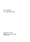
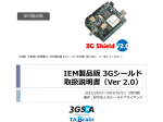
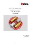
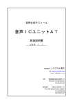
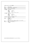
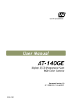
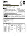
The evaluation board for
TOSHIBA TMPM369FDFG
user's manuals
Revision 1.2.0
2014/11/27
A product specification is an object of change without a preliminary announcement
・Introduction
This manual is a user's manual of the evaluation board for Toshiba TMPM369FDFG.
・Table of contents
Chapter 1, Outline
Chapter 2, Hardwar discription
・Revision history
Date
Revision
2012/9/12
Revision 1.00
2013/4/25
Revision 1.10
2014/11/27
Revision 1.20
Sheet
Contents
numbe
First edition creation
default jumper configuration
JP5:OPEN →JP5:CLOSE
p7
5, 16-bit timer (TMRB)
16 channels -> 8 channels
p9
24, Interruption function
・ 110 kinds of insides
-> 112 kinds of insides
・ 17 kinds of exteriors : (NMI is included).
-> 16 kinds of exteriors : (NMI is
excluded)
33, Package
・LQFP144-P-2020-0.5 -> LQFP144
Chapter 1, Outline
Evaluation Board for TOSHIBA TMPM369FDFG enable you to create and test working programs
based on the Toshiba TMPM360 family of ARM Cortex™-M3 processor-based devices
【Features】
■ 80MHz ARM Cortex™-M3 processor-based MCU in 144-pin LQFP
■ On-Chip Flash: 512KB (TMPM369FDFG)
On-Chip Flash: 256KB (TMPM369FYFG)
■ On-Chip RAM: 128KB (TMPM369FDFG)
On-Chip RAM: 64KB (TMPM369FYFG)
■ USB 2.0 Host
■ USB 2.0 Device
■ CAN 2.0B Interface
■ EterMAC (10/100Base-T)
On a board LAN-PHY made from SMSC (LAN8710A) is mounted.
■ 12bit ADC(16ch : AINA0~AINA3, AINB0~AINB11)
Multi-rotation volume for ADC Input(2ch-only:AINA0、AINB6)
■ 10bit DAC(2ch : DA0,DA1)
■ SIO/UART ch0〜ch3
Only the channel 0 equips DSUB-9pin connector with a RS-232C driver / receiver..
■ Full/UART ch4〜ch5
Only the channel 4 equips DSUB-9pin connector with a RS-232C driver / receiver..
■ 5 LEDs and 6 push-buttons
LED1〜LED4 --- Status display LED (This LED is connected to PC7〜PC4 of a port. )
LED5 :LED for power light
S1: Push switch for /reset
S2: Push switch for /NMI
S3〜S6 : Push switch for a test
■ Power via USB connector
As an option An AC adaptor jack (CN13)
and an external 5V-Power input connector (CN1) are equipped.
(However, in order to usually perform electric supply from a USB connector,
CN1 and CN13 suppose un-mounting.)
■ Debug Interface Connectors
■10-pin Cortex debug (0.05 inch connector)
■20-pin Cortex debug + ETM Trace (0.05 inch connector)
■20-pin (0.10inch connector) - ARM Standard JTAG Connector
(Page1)
+3.3V
VAA3.3
TMPM369FDFG
【Fig.1】
Evaluation_for_TOSHIBA_
TMPM369FDFG whole_block_diagram
AVDD
LAN8710AI
DVDD
DVSS
AVSS
CN11
AGND
DGND
GPIO
&
EBIF
CN12
Expantion
_Connector
GPIO
&EBIF
MII
25MHz
USBHPON
PK3/USBHPON/SP0DO/SIO_SCL0
TPS2051C
PK1/USBOC/SP0FSS/INT8/TB6OUT
USB
_Host
MPT
(PMD)
Bus_Power
27
USB Host
CN3
(TYPE_A )
USBH0P
27
15K
VAA3.3
15K
ADC_input(AINA0)
10K_Volume
CN10
+5V
Current_Limited_IC
/USBOC
MPT(PMD)
Output
10/100Base-T Ethernet_
10/100Base
Ethernet_PHY
MII
信号
(17Pin)
SN65220
TRANSIENT
_SUPPRESSORS
0
PI0/AINA0/INT9
PK0/USBDPON/(INTD)
USP_PON
0.1u
USB_DDP
USBDP
USB0M
ADC Input
AGND
PI0/AINA0/INT9
12bit
_ADC
(16ch)
USB_DDM
USB
_Device
PJ2/AINB6
CAN
VAA3.3
ADC_input(AINB6)
10K_Volume
0
CAN-transceiver
CTXD
DAC Output
10bit
_DAC
(2ch)
PJ2/AINB6
TJA1040
60
JP12
CN9
120
60
CRXD
CAN
1000p
0.1u
AGND
Full
_UART
ADM3202ARU
CN8
Full-UART
RTS4
SSP
External-5V
-power-input
CN1
RXD4
CTS4
User_LED x4
J_3.3V
LED1~LED4
(no-mount)
+5V
CN13
JP6
(n o- moun t)
JP7
LDO
Common
_Mode
_Filter
EXT _5V
RXD0
+3.3V
LED5
GPIO
J P13
GND_IN
PB6/BELL/SCOUT/TB3OUT/ BOOT
JP1
NMI-SW
/NMI
JP2 3 2 1
S2
PE2/TXD0/A2/A18/TB1OUT
JP3 3 2
USB Device
U_5V
CN2
PK0/USBDPON/(INTD)
Filter
1
PE3/SCLK0/A3/A19/CTS0/TB0OUT
JP4 3 2
1
RESET-SW
/RESET
PE5/TXD1/A5/A21
27
S1
USB_DDP
27
JP8
SN65220
1.5K
1Mx2
+3.3V
TRANSIENT
_SUPPRESSORS
PE0/A0/A16/INT4/TB0IN
USB_DDM
PE0/A0/A16/INT4/TB0IN
1 6MHz
DTC12 3
J P10
XT1
3 2.7 68
KHz
10-pin Cortex debug
(0.05 inch connector)
X1
X2
DTA 123
JP9
CN7
SIO/UART
RS-232C
DRV/REV
TXD0
S3~S6
JP5
AC-adapter-jack
ADM3202ARU
SIO_
UART
+3.3V
User_Push-Sw×4
USB-miniB
(TypeB)
RS-232C
DRV/REV
TXD4
/Debug
I/F
CN4
J_3.3V
CN5
20-pin Cortex debug
+ ETM Trace
(0.05 inch connector)
CN6
20-pin (0.10inch connector)
- ARM Standard JTAG Connector
JTAG
XT2
JP11
(Page2)
【Fig.2】
Evaluation_for_TOSHIBA_
TMPM369FDFG
PCB Main parts image
135.0
mm
4-3.2Φ
5mm
3 1
71
5mm
CN11
JP5
72
Full-UART
(DSUB-9PIN)
CN8
S4
U7
100.0
mm
USBHost
USBDevice
CN13
37
72
U4 U5
73
36
CN5
JP4
CN7
U6
CPU
(U1)
U8
CN4
JP2
1
144
VOL2
VOL1
S1
Y2
106
L3
S2
107
Y1
DC- IN
74
CN9
Y3
U9
CN1 JP6 JP7
CAN
JP12
U2
(LDO)
JP8 JP11
CN2
(20PIN-JTAG)
JP3
JP10
JP9
U3
DCJACK
JP1
U10
JP13
CN3
CN6
(10PINCortex-Debug)
S5
S6
U11
SIO-UART
(DSUB-9PIN)
4 2
(20PIN-Cortex
-Debug+ETM)
S3
LAN
CN10
LAN-PHY
CN12
73
144
5mm
143
5mm
U1
U2
CPU
LDO
TMPM369FDFG (TMPM369FYFG)
LD1117S33CTR
TOSHIBA
ST-Microelectronics
U3
U4
U5
USB-Transient-Suppressor
Digital Transistor PNP
Digital Transistor NPN
RS-232C
Line Drivers/Receivers
RS-232C
Line Drivers/Receivers
CAN TRANSCEIVER
SN65220DBVT
DTA123EE
DTC123EE
TI
Rohm
Rohm
ADM3202ARUZ
Analog Devices Inc
ADM3202ARUZ
Analog Devices Inc
TJA1040T
NXP Semiconductors
U6
U7
U8
U9
U10
U11
LAN-PHY
LAN8710AI
Current-Limited,
Power-DistributionTPS2051CDBVT
Switches
USB-Transient-Suppressor SN65220DBVT
SMSC
TI
TI
(Page3)
4- 3 . 2 Φ
135.0
mm
5mm
3 1
71
5mm
CN11
JP5
72
Full-UART
(DSUB-9PIN)
CN8
S4
U7
U1 1
USBHost
USBDevice
CN13
37
36
72
JP10
U4 U5
JP4
JP3
73
CPU
(U1)
JP2
1 2 3
1 2 3
CN5
CN7
U6
U8
CN4
1
144
VOL2
VOL1
(LDO)
S1
Y2
106
Y1
L3
S2
107
DC- IN
74
CN9
Y3
U9
CN1 JP6 J P7
CAN
JP12
U2
JP8 JP11
CN2
DCJACK
JP1
U10
JP9
U3
(20PIN-JTAG)
1 2 3
JP13
CN3
CN6
(10PINCortex-Debug)
S5
S6
100.0
mm
SIO-UART
(DSUB-9PIN)
4 2
(20PIN-Cortex
-Debug+ETM)
S3
LAN
CN10
LAN-PHY
CN12
73
144
5mm
143
5mm
J u m p e r C LO SE
【Fig.3】
Evaluation_for_TOSHIBA_
TMPM369FDFG
Jumper configration (default)
Default configuration
JP7:OPEN
→ With no electric supply
JP1:OPEN
→ Normal
JP8:OPEN
→ With no pull-up
JP2 :2-3 CLOSE
→ X1 OSC select
JP3:1-2 CLOSE
→ X1 OSC(16*3)
JP4:2-3 CLOSE
→ SIO BOOT
JP5:CLOSE
→ Target_board power
supply to CN6-1PIN
JP6:CLOSE
→ It supplies from
a USB Device connector
(CN2)
JP9:CLOSE
→ USB_DP terminal
1MΩ pull-down
JP10:CLOSE
→ USB_DM terminal
1MΩ pull-down
JP11:CLOSE
→ Control port (PE0)
It is used.
JP12:OPEN
→ Termination is not used.
JP13:CLOSE
→ The regulator output
on a board is used
(Page4)
【Table.1】
Evaluation Boardfor TOSHIBA TMPM369FDFG
【 Jumper pin setting table】
Reference
The number
of pins
Silk name
Function
JP1
2PIN
JP1 /BOOT
・Boot mode select
JP1:OPEN → Normal
JP1:CLOSE → BOOT Mode
JP2
JP3
JP4
JP5
JP6
JP7
3PIN
3PIN
3PIN
2PIN
2PIN
2PIN
JP2
1 USBCLK
2
3 X1 OSC
・Selection of a clock
JP2:1-2 CLOSE→ USBCLKl
JP2:2-3 CLOSE→ X1 OSC
JP3
1 X1 OSC(16*3)
2
3 USB_ECLK
・USB Clock selection
JP3:1-2 CLOSE→ X1 OSC(16*3)
JP3:2-3 CLOSE→ USB_ECLK
JP4
1 USB_BOOT
2
3 SIO_BOOT
・Boot mode kind selection
JP4:1-2 CLOSE→ USB BOOT
JP4:2-3 CLOSE→ SIO BOOT
JP5 JTAG_POWER
・3.3V target supply source selection
JP5:OPEN → With no target supply to CN6-1pin
JP5:CLOSE → It supplies target +3.3V-power to JTAG(CN6-1pin)
JP6 USB_5V
・5V electric supply source selection
JP6:OPEN → With no electric supply
JP6:CLOSE → It supplies from a USB Device connector
(CN2)
JP7 EXT_5V
・5V electric supply source selection
JP7:OPEN → With no electric supply
JP7:CLOSE → It supplies 5V from
an external connector (CN1 or CN13).
・USB_DP terminal 1.5KΩ Compulsive pull-up
JP8:OPEN → With no pull-up
JP8:CLOSE → USB_DP terminal Compulsive pull-up
JP8
2PIN
JP8 DP_PULL-UP
JP9
2PIN
JP9 DP_PULL-DOWN
・USB_DP terminal 1MΩPulldown
JP9:OPEN → With no pull-down
JP9:CLOSE → USB_DP terminal 1MΩ pull-down
JP10
2PIN
JP10 DM_PULL-DOWN
・USB_DM terminal 1MΩPulldown
JP10:OPEN → PULL-DOWN無し
JP10:CLOSE → USB_DM terminal 1MΩ pull-down
・USB_DP terminal Compulsive pull-up control port (PE0) enabling
JP11
2PIN
JP11 PE0-EN
JP11:OPEN → Control port (PE0) It is not used.
JP11:CLOSE → Control port (PE0) It is used.
(Page5)
Chapter 2, Hardwar discription
The TMPM369FDFG is a 32-bit RISC microprocessor series with an ARM Cortex-M3 microprocessor core..
The internal composition of CPU is shown in Fig.4.
【 F ig . 4 】 TM P M3 6 9 F D F G C P U i n t e r n a l b l o c k _ d i a g r a m
C or t e x - M 3
JT AG / SW D
ETM
Ether
MAC
NVIC
USB
Device
μ DM A
A H B L i te B u s Ma t r i x
F L AS H_ ROM
Main_RAM
MP T/ PMD /ENC
CG
Backu p_RAM
Ethe r_ MAC
WDT
AHB to I/O Br ige
U S B _H O ST
AHB Lite Bus 0
B O OT _ RO M
PORT
RTC
1 6bi t TIM ER
SIO/ UART
( 4byte FIF O )
USB_ Devi ce
SBI
OFD
CAN
RM C
A HB to APB Br idge
1 2b it ADC
1 0b it DAC
SSP(SPI)
Ext er na l_ B US _ I/F
F u ll- UAR T
(Page6)
【CPU functional outline】
1,ARM Cortex-M3 microprocessor core
(a),. Improved code efficiency has been realized through the use of Thumb-2 instruction.
・ New 16-bit Thumb instructions for improved program flow
・ New 32-bit Thumb instructions for improved performance
・ New Thumb mixed 16- / 32-bit instruction set can produce faster, more efficient code.
(b),. Both high performance and low power consumption have been achieved.
[High performance]
・ Both high performance and low power consumption have been achieved.
・ Division takes between 2 and 12 cycles depending on dividend and devisor
[Low Power consumption]
・ Optimized design using a low power consumption library
・ Standby function that stops the operation of the micro controller core
(c),..High-speed interrupt response suitable for real-time control
・ An interruptible long instruction
・ Stack push automatically handled by hardware
2, High-speed writing which demonstrates an effect at the time of
high-speed write-in & low power consumption
and mass production by Toshiba NANO FLASH- technology, and development
3, On Chip program memory and data memory
・ On-Chip Flash: 512KB (TMPM369FDFG)
On-Chip Flash: 256KB (TMPM369FYFG)
・ On-Chip RAM: 128KB (TMPM369FDFG)
On-Chip RAM: 64KB (TMPM369FYFG)
4, DMA controller (DMAC): 32 channel / 2 unit
The candidate for transmission: A built-in memory, built-in I/O, and an external memory
5, 16-bit timer (TMRB) : 8 channels
・16-bit interval timer mode
・16-bit event counter mode
・16-bit PPG output (4channel timer can start synchronously)
・Input capture function
6, Real time clock (RTC) : 1channel
・Clock (hour, minute and second)
・Calendar (month, week, date and leap year)
・Alarm (Alarm output)
・Alarm interrupt
7, Watchdog timer (WDT) : 1 channel
Watchdog timer (WDT) generates a reset or a non-maskable interrupt (NMI).
・26 Stage binary counter
・ Watchdog timer out function
8, General-purpose serial interface (SIO/UART) : 4 channels
Either UART mode or synchronous mode can be selected (4byte FIFO equipped)
(Page7)
9, Serial bus interface (I2C/SIO):: 3 channels
Either I2C bus mode or synchronous mode can be selected.
10, Synchronous serial port (SSP) : 3 channels
Support SPI / SSI / Microwire
11, Full UART:2 Channel
8-Line Type UART / IrDA 1.0 Mode Select is Possible.
12, 10-bit AD converter (ADC) : 16 channels
・Start by an internal timer trigger
・Fixed channel / scan mode
・Single / repeat mode
・AD monitoring 2 channels
・Conversion speed 1.0 μsec (@ fsys = 80 MHz、Normal_Mode)
・Fast conversion by interleave mode (conversion time : a maximum of 0.5microsec)
13, 10bit DA Converter (DAC) : 2 Unit (2 Channel)
・ VREFH cut function (Power down mode)
・ Output current : 1 mA
・ Seduced time : 1microsec
・ Signal generation function
14, USB2.0 Full Speed Device : 1 Channel
・ It is based on Universal Serial Bus Specification Rev2.0.
・ End point : 8 channel
・ Control/Bulk/Interrupt/Isochronus mode
・ Full speed 12Mbps (low speed is un-supporting)
15, USB host controller : 1 channel
・Universal serial bus (Rev 2.0 standard)
・Open HCI for USB Release 1.0a
・・Control/Bulk/Interrupt/Isochronus mode
・12Mbps(full speed) :(Low speed is un-supporting)
16, CAN : 1 channel
・Version 2.0B supported
・32 mail boxes
・Maximum transfer speed : 1 Mbps
17, Ethernet MAC:1 Channel
・ IEEE802.3u conformity
・ Flow control (IEEE802.3x / back pressure system)
・ 10Mbps / 100Mbps correspondence
・ MII (Media Independent Interface) correspondence
・ High-speed communication by exclusive DMA and a total of 8-K byte FIFO
・ Magic packet detection function
18, Remote Control Judging Function (RMC) : 1 Channel
・ It is package reception to 72bit.
・ Noise canceller function
・ Reader code detection function
(Page8)
19, Multiple-purpose - timer (MPT):4 channel
・motor control (PMD:2 channel)
・IGBT control
・16-bit timer
20, Encoder input function: 2 channel
・Incremental form encoder correspondence
21, LVD/POR Function : 1 Unit
22, Oscillation Frequency Detection :1 Unit
23, External bus interface: : 1 unit
・separation / multiplexer bus : 8 bit / 16 bit width
・ chip select / wait controller: : 4 channel
24, Interruption function
・ 112 kinds of insides : a priority setup of 7 level is possible.
(Watchdog timer interruption is excluded)
・ 16 kinds of exteriors : a priority setup of 7 level is possible (NMI is excluded)
25, Input / output ports (PORT)
・I/O port : 101 pins
・Output port : 1 pins
26, Standby function
・Standby mode : IDLE, STOP1, STOP2
・IDLE ::CPU stop
・STOP1/STOP2:: All the circuit stops except RTC and a remote control judging circuit
(STOP2 At the time of the mode in part a circuit power supply interception)
27, Clock Generator
・ PLL built-in (3, 4, 5, 6, 8, and 10times PLL frequency change is possible)
・ Clock gear function : dividing is possible in a high-speed clock to 1/1, 1/2, 1/4, 1/8, and 1/16.
28, Endian
・Little endian
29, Debugging interface
・JTAG/SWD/SWV/TRACE(DATA 4bit)
30, Maximum operating frequency
・80 MHz
(the time of external oscillator 8MHz, 10 MHz, or 16MHz use
or built-in oscillator 10MHz use )
31, The range of operating voltage
・2.7V~3.6V (at the time of USB functional disuse)
・3.0V~3.6V (at the time of USB functional use)
32, Operating temperature range
・ −40℃~~ 85℃ (Except the time of flash writing / erase)
・ 0℃ ~ 70℃ (At the time of flash writing / erase)
33, Package
・LQFP144 (20mm x 20mm, 0.5mm pitch)
(Page9)