1
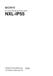
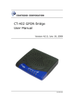
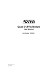
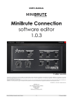
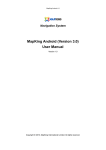
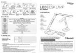
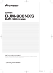
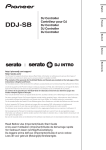
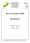
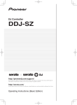
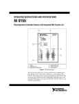
IP LIVE PRODUCTION UNIT
NXL-IP55
OPERATION MANUAL
1st Edition (Revised 2)
[English]
Table of Contents
Overview ......................................................3
Features......................................................... 3
Transmittable Signals ................................... 3
Supported Networks ..................................... 3
System Configuration Examples ...............4
3-Camera System.......................................... 4
2-Camera System.......................................... 5
1-Camera System.......................................... 6
System Using Cameras Unable to Output
SDI Audio Signals............................... 7
Configuration Example when Using
Intercom .............................................. 8
Tally Signal Usage Example ........................ 8
GPIO Signal Usage Example........................ 8
Names and Functions of Parts...................9
Front.............................................................. 9
Rear............................................................... 9
Settings ......................................................11
Configuring Settings................................... 11
Input/Output Phases for HD-SDI Signals... 15
Settings Examples....................................... 17
Operation ...................................................20
Starting Video Transmission ...................... 20
Outputting Color Bars and Tone Signal ..... 20
Displaying the Status .................................. 20
Menus .........................................................21
Menu Structure ........................................... 21
[Status] Page ............................................... 21
[Operator] Page........................................... 24
[I/O] Page.................................................... 26
[Structure] Page .......................................... 29
[Network] Page........................................... 31
[Others] Page .............................................. 32
Specifications ............................................34
External Interfaces ....................................35
Notice on GNU GPL/LGPL Licensed
Software ..............................................36
2
Table of Contents
Overview
intercom signals embedded on HD-SDI signals (up to
eight channels in the same direction).
Notes
Features
The NXL-IP55 IP Live Production Unit is an IP
transmission device that allows upstream and
downstream transmission of HD video signals, audio
signals, and various control signals with low latency of
less than one field (excluding network delays). Using the
unit allows you to configure a live production system over
a network.
Network synchronization
Devices can be synchronized via a network. Low-latency
video transmission is made possible during live
production by eliminating the need for synchronization
via a frame synchronizer.
Various transmission signals
Up to four video channels are available for transmission
with up to three in the same direction. Ten audio channels
(five pairs) are available for transmission with eight in the
same direction. Eight GPIO channels, six tally channels,
and one channel for a synchronization signal are also
available.
Note
The content of this document applies to firmware version
V1.20.
NXL-IP55 units with different firmware version cannot
be connected together. You can check the firmware
version in [Device Information] on the [Status] page in
the Web menu.
If using an NXL-IP55 unit with a different firmware
version, contact your store or point of purchase.
Transmittable Signals
Video signals
1080/50i, 1080/59.94i, 720/50P, 720/59.94P,
1080/25PsF, 1080/29.97PsF
Can transfer up to four channels of HD SDI signals,
with up to three in the same direction.
1080/50P, 1080/59.94P
Can transfer total of two channels using Dual Link
SDI, with one in each direction.
Note
Signals with different formats cannot be transferred at the
same time.
• HD-SDI embedded audio can be transmitted on Ch1 to
Ch2 or Ch1 to Ch4. The audio will not be transmitted
on Ch5 and above.
Metadata attached to HD-SDI signals cannot be
transmitted.
• When transferring Dual Link SDI, audio signals can be
embedded in Link-A only.
Tally signals
Three channels each are available for R tally signals and
G tally signals.
However, the transmission direction for all channels is the
same.
GPIO
Eight channels are available.
The transmission direction can be switched by using four
channels as one group.
Supported Networks
Use this unit in a network that meets the following
specifications. Check whether the network you want to
use fulfills these requirements by performing a network
test in the web menu before use.
Note
The network test only displays the status of the area that
can be detected at the moment the test is executed. It does
not guarantee the quality of the network or the operation
of this unit.
Network connected to the MAIN connector
This network connects to the unit’s MAIN connector and
transmits video signals and control signals.
The requirements for this network are as follows.
• The network is a secure LAN independent from other
systems and networks. It cannot be used as a WAN or
Internet line.
• Use a switch with 5 or less levels.
• Interface: 1000BASE-T
• MTU: 1500 bytes or higher, no fragments
• Latency: 10 ms or less without fluctuation (one way)
• Bandwidth: 600 Mbps or more maintained
Network connected to the CONTROL connector
This network connects to the unit’s CONTROL connector
and connects the computer used to configure this unit.
• Interface: 100BASE-TX
Audio signals
Up to five pairs of two channels (48 kHz/24 bit) are
available for audio signals, analog audio signals, and
Overview
3
System Configuration Examples
3-Camera System
The main line signals from three cameras can be transmitted. One channel is available for transmitting return signals.
Camera 1
Return signal (HD-SDI)
Main line signal 1 (HD-SDI)
Tally signal
Synchronization signal
Camera 2
Return signal (HD-SDI)
Main line signal 2 (HD-SDI)
Tally signal
Synchronization signal
Camera 3
Return signal (HD-SDI)
Main line signal 3 (HD-SDI)
Tally signal
Synchronization signal
NXL-IP55
Network
Main line signals 1 to 3 (HD-SDI)
NXL-IP55
Return signal (HD-SDI)
Synchronization signal
Video router
4
System Configuration Examples
Tally signal
2-Camera System
The main line signals from two cameras can be transmitted. Two channels are available for transmitting return signals.
Camera 1
Return signals 1 and 2 (HD-SDI)
Main line signal 1 (HD-SDI)
Tally signal
Synchronization signal
Camera 2
Return signals 1 and 2 (HD-SDI)
Main line signal 2 (HD-SDI)
Tally signal
Synchronization signal
NXL-IP55
Network
Main line signals 1 and 2 (HD-SDI)
NXL-IP55
Return signals 1 and 2 (HD-SDI)
Synchronization signal
Tally signal
Video router
System Configuration Examples
5
1-Camera System
The main line signal from one camera can be transmitted. Three channels are available for transmitting return signals.
Camera 1
Return signals 1 to 3 (HD-SDI)
Main line signal 1 (HD-SDI)
Tally signal
Synchronization signal
NXL-IP55
Network
NXL-IP55
Main line signal (HD-SDI)
Return signals 1 to 3 (HD-SDI)
Video router
6
System Configuration Examples
Synchronization signal
Tally signal
System Using Cameras Unable to Output SDI Audio Signals
When using cameras that cannot embed audio signals onto HD-SDI signals, you can input analog audio signals via a
separate channel and map them onto HD-SDI signals for transmission. As audio input levels are at line level, an external
microphone amplifier is necessary when using a microphone.
Microphone
Camera 1
Main line signal 1 (HD-SDI)
Tally signal
Synchronization signal
Camera 2
Main line signal 2 (HD-SDI)
Microphone
amplifier
Tally signal
Synchronization signal
Camera 3
Analog
audio
signals
Main line signal 3 (HD-SDI)
Tally signal
Synchronization signal
NXL-IP55
Network
Main line signals 1 to 3 (HD-SDI) 1) NXL-IP55
Tally signal
Synchronization signal
Switcher
1) Audio signal inputs are embedded.
System Configuration Examples
7
Configuration Example when Using Intercom
Connecting an intercom system to this unit’s AUDIO/INTERCOM connector enables intercom transmission and allows
you to combine two intercom systems.
PROD
Intercom system
ENG
NXL-IP55
Camera control unit
Camera
Network
NXL-IP55
PROD
Intercom system
ENG
Tally Signal Usage Example
GPIO Signal Usage Example
Two channels per camera for three cameras are available
for transmitting tally signals via the unit’s TALLY/GPIO
connector.
Two groups of four GPIO (General Purpose Input/
Output) signals can be transmitted via the unit’s TALLY/
GPIO connector. The transmission direction can be
changed for each group.
GPIO group 1
GPIO group 2
NXL-IP55
Network
NXL-IP55
NXL-IP55
Network
NXL-IP55
GPIO group 1
: Red tally
: Green tally
8
System Configuration Examples
GPIO group 2
Names and Functions of Parts
Front
1
2
a Power switch / indicator
This is the power switch. The indicator lights when the
unit is turned on. Stable output of video signals may take
some time after the unit is turned on. The LINK indicator
will blink or light blue and video signals will not be
output until proper output is established.
To turn the unit off, press and hold the switch for at least
2 seconds.
3
Blinking blue: Connection is being established. As the
connection process progresses, the indicator blinks
more rapidly.
Lit blue: Connection has been established, and the unit
is waiting for signal output to stabilize. Video
signals are not output during this time.
Off: Not connected to the LAN.
c ALARM indicator
Lights red when an error is detected.
Check the [Status] page of the web menu for details on the
error.
The indicator blinking red indicates an internal error. If
restarting the unit does not resolve the problem, consult
your Sony service representative.
b LINK indicator
Indicates the connection status.
Lit green: Connected to the partner device.
Blinking green: Connected to the partner device, but
there is a problem with the status of the network
connected to the MAIN connector.
Rear
1
2
5
3
6
a REF IN connector
Inputs the synchronization signal.
Input is not necessary when using the SDI signal as a
synchronization signal, or when the synchronization
setting is set to [Follower] and a frame synchronizer is not
used.
4
7
8
9 0
b REF OUT connectors (1/2/3)
Output synchronization signals. The same signal is output
from each of these three ports.
Notes
• The subcarrier phase during black burst signal output is
not guaranteed.
• The accuracy of frequencies when synchronization is
not applied to unit is not guaranteed.
Names and Functions of Parts
9
c HD SDI IN connectors (1/2/3)
Input SDI signals for transmission.
When using an SDI signal as the synchronization signal,
input it to HD SDI IN connector 1.
d HD SDI OUT connectors (1/2/3/4/M)
Output transmitted SDI signals or SDI signals that were
input to this unit.
Monitor signals are output from HD SDI OUT connector
M. Text information can be superimposed onto outputs
from this connector. Monitor output can be selected using
the web menu.
j Clamp attachment point
Attach the supplied clamp here. Open the tab (1) to pass
the power cable through the clamp.
To remove the clamp, push the tabs (2) in the direction
of the arrows.
2
Note
When outputting signals that are input to this unit, a delay
of 1 or 2 lines may occur.
e AUDIO/INTERCOM connector
Connects to analog audio equipment and intercom
systems.
The AUDIO/INTERCOM and TALLY/GPIO connectors
are both 25-pin D-sub connectors. Be sure to check the
labels to avoid incorrect connections.
f MAIN connector
This is a network connector that supports 1000BASE-T.
Video signals and control signals are transmitted between
multiple units of this device via a gigabit network.
This single connector has two IP addresses.
Notes
• Always connect to a 1000BASE-T network. The unit
will not operate with other network types.
• Connect the unit using a CAT5e LAN cable or above.
g CONTROL connector
This is a network connector that supports 100BASE-TX.
Connect a computer to this connector, and use it to
configure settings for this unit via the web menu. If you
do not need to display or operate the web menu, this
connection is not necessary.
Video signals cannot be transmitted from this connector.
h TALLY/GPIO connector
Inputs/outputs tally signals or GPIO signals.
i DC IN connector
Connects to the supplied AC adapter.
Note
For safety, use only the AC adapter supplied with this
unit.
10
Names and Functions of Parts
2
1
Subnet mask: 255.255.255.0
Default gateway: 192.168.0.253
The network settings can be checked via the [Status] page
of the web menu or via the text information superimposed
on the monitor output.
Settings
Configuring Settings
Perform the following to configure settings.
1.
Connecting the computer (required)
2.
Changing the password
2. Changing the password
User names and passwords can be changed on the
[Others] page.
Password entry is required to display pages other than the
[Status] page and [Operator] page. The factory default
user name and password are as follows.
User name: Users
Password: NXL-IP55
3.
Network settings (required)
4.
Format settings (required)
5.
Video transmission settings (required)
6.
Synchronization settings (required)
7.
Transmission rate settings (required)
3. Network settings
8.
Audio signal settings (required)
9.
Tally signal settings (required)
The network settings are configured on the [Network]
page.
Settings must be configured for the MAIN connector
network, which transmits the main line signal, and the
CONTROL connector network, which connects to the
computer used to setup this unit.
10. GPIO settings (required)
11. Date and time settings
12. Changing the web menu title
13. Backing up and restoring settings
14. Importing and exporting settings
15. Verifying settings
16. Verifying the network environment
1. Connecting the computer
A computer can be connected to this unit’s CONTROL
connector using a LAN cable (either straight or cross).
LAN cable
Open a web browser on the computer, and enter “http://
192.168.0.3” (or an amended IP address) in the address
field.
The web menu used to configure this unit appears.
Note
When configuring settings, be sure to click the [Apply]
button after configuring settings in each web menu page.
If you switch to a different page or close the web browser
without clicking the [Apply] button, the settings will not
be applied.
The factory settings for this unit’s CONTROL connector
are as follows.
IP address: 192.168.0.3
MAIN connector settings
These are configured under [Main Port Configuration] on
the [Network] page.
Although it is one connector, it has two IP addresses –
Main 1 and Main 2. When you configure the IP address
for Main 1, a sequential IP address is configured for Main
2 automatically. Make sure that the IP addresses do not
overlap with other devices.
• [Host IP Address (1/2)]: Enter the IP address for Main 1.
• [Host IP Address (2/2)]: This is configured
automatically when you enter an address for [Host IP
Address (1/2)]. This cannot be modified.
• [Subnet Mask]: This setting is the same for Main 1 and
Main 2.
• [Destination IP Address (1/2)]: Enter the Main 1 IP
address of the other connected NXL-IP55 unit (i.e., the
connection destination).
• [Destination IP Address (2/2)]: This is configured
automatically when you enter an address for
[Destination IP Address (1/2)]. This cannot be modified.
• [Destination Subnet Mask] / [Gateway]: Enter the subnet
mask of the partner unit’s MAIN connector and the
gateway of the local unit when operating between
different segments. This item is enabled when you select
the [Main Port Gateway] checkbox in the [Others] page
and click [Apply].
• [Speed]: Displays the connection speed.
• [Stream Mode]: Set to “Multicast” if using the PC
application software (optional), or set to “Unicast”
otherwise.
Notes
• In Multicast mode, multicast packets are sent from
the switch to all ports, which may affect
communication on other ports. In order to avoid this,
use the IGMP snooping function and IGMP query
function of the switch to monitor traffic, or take other
Settings
11
measures such as segmenting the network connected
to the MAIN connector and the network with the
CONTROL connector using VLANs.
• When [Main Port Gateway] is enabled under
[Function Enable] in the [Others] page, operation in
Multicast mode is disabled.
• [Multicast Address]: If “Multicast” is configured in
[Stream Mode], set the IP addresses. Six addresses are
required. Setting one address automatically sets the
remaining five addresses in sequence. Set corresponding
addresses on the connected devices. If “Unicast” is
configured in [Stream Mode], no entry is required.
• [Register IP Address]: If a computer running the PC
application software (optional) is connected, enter the
IP address of the computer. Set [Stream Mode] to
“Multicast” to configure this parameter. The required
address is the IP address of the computer connected to
the same network segment as the MAIN connector of
the unit. IP addresses for up to eight computers can be
configured.
CONTROL connector settings
These are configured under [Control Port Configuration]
on the [Network] page.
• [DHCP]: Select whether to use DHCP. When using
DHCP, the IP address allocated to the unit can be
monitored using character information superimposed
on the monitor output.
• [IP Address], [Subnet Mask], [Default Gateway]:
Configure these if [DHCP] is disabled.
Note
When specifying IP addresses for the MAIN connector and
the CONTROL connector, do not use multicast addresses,
broadcast addresses, or other special reserved addresses.
4. Format settings
Select the image format for transfers under [Video
Format] in the [Structure] page.
5. Video transmission settings
The direction of the video’s main line signal and the
number of transceiver channels are configured under
[Transmission Settings] on the [Structure] page.
• [Main Video Direction]: Select [Transmitter] for the
camera transmitting main line signals, and [Receiver]
for the video router receiving the signals.
On the Receiver side, the phases of the input SDI signals
and the SDI signals sent from the Transmitter will match.
On the Transmitter side, the phases of the input SDI
signals and the SDI signals sent from the Receiver will
not match (when [Frame Synchronizer] is [OFF]).
Selecting the [Transmitter] and [Receiver] establishes a
pair. Communication will not be possible if both sides
are set identically.
• [Structure]: Configure the number of transmitter/
receiver channels. The number of channels for the
Transmitter and the Receiver should be inverted.
For example, in a 3-camera system with one return
12
Settings
channel, specify [3Transmit 1Receive] for the cameras
and [1Transmit 3Receive] for the video router.
Alternatively, if [3Transmit 1Receive] is specified,
specify [1Transmit 3Receive] for the partner device. If
[2Transmit 2Receive] is specified, specify [2Transmit
2Receive] again for the partner device.
If “1080/59.94P (Dual Link)” or “1080/50P (Dual
Link)” is selected in [Video Format], [Structure] is
fixed to “2Transmit 2Receive” and Dual Link 1
operates in bidirectional transfer mode. Connect the
Link-A input to HD SDI IN connector 1, and the LinkB input to HD SDI IN connector 2. The HD SDI IN 3
connector is disabled. Connectors HD SDI OUT 1 and
2 are grouped, as are connectors HD SDI OUT 3 and 4.
Link-A is output from connectors HD SDI OUT 1 and
3, and Link-B is output from connectors HD SDI OUT
2 and 4.
6. Synchronization settings
Configure synchronization between transmission
devices.
Selection of whether a device is the Leader or Follower in
regards to the synchronization signal is performed under
[Network GenLock] on the [Structure] page.
Select [Leader] for the transmitting device, and
[Follower] for the subordinate device. Transmission is
not possible between two Leader devices or two Follower
devices.
Next, select the synchronization signal to be input under
[Reference in] on the [I/O] page.
• [Source]: Select either the input signal from the REF IN
connector or from HD SDI IN connector 1 to be the
synchronization signal.
• [Format]: When [Reference in] is selected for [Source],
select [HD] (HD 3-value sync) or [SD] (SD sync).
• [V Phase]: Enter this unit’s vertical phase for the input
synchronization signal.
The input signal must be in phase with this unit.
However, an unsynchronized signal can be input if there
is only one channel. In such cases, use the frame
synchronizer. For details, see “Settings when using a
frame synchronizer” on page 18.
The synchronization signal to be output from the REF
OUT connector is configured under [Reference out] on
the [I/O] page.
• [Format]: Select [HD] (HD 3-value sync), [SD (BB)],
or [SD (SYNC)] (SD sync) as the synchronization
signal to be output.
• [V Phase]: Enter this unit’s vertical phase for the output
synchronization signal.
Note
Configure the [Reference in] and [Reference out] settings
for both the NXL-IP55 Leader and Follower units.
7. Transmission rate settings
9. Tally signal settings
The transmission rate for video signals is configured
under [Video Code Rate] on the [Structure] page.
Configure identical settings for both the NXL-IP55
sender and receiver units. Configuring a high rate enables
high-resolution images, but requires a large transmission
band.
The transmission direction of a tally signal is selected
under [Signal Direction] on the [Structure] page.
• [Tally]: Select [Transmitter] for the tally signal
transmitter, and [Receiver] for the receiver. The
transmission method cannot be changed on an
individual basis.
Note
Next, specify the interface for the input tally signal under
[Tally Input] on the [I/O] page.
• [Tally Input]: Select [Contact] or [Power (TTL)].
Output is fixed at [Contact].
Lower rates are using for monitoring mode. Use after
checking the image quality.
When the [Disable] checkbox is selected, that channel
will not be used for transmission. If the transmission band
is small, selecting the [Disable] checkbox for unnecessary
channels will secure the required bandwidth.
8. Audio signal settings
Transmission channel settings
The audio signal to be transmitted is selected under
[Audio Select] on the [Structure] page.
Select the checkboxes of the channels you want to use for
transmission. Up to five boxes (10 channels) can be
selected (or up to 8 channels in the same direction). For
the intercom, 1 channel each is used for the round trip.
When both the [ENG] and [PROD] checkboxes are
selected, 2 channels each are used for the round trip.
Audio signal settings
Audio signals to be input/output are configured on the
[I/O] page.
• [Embedded Audio Enable]: Select whether to embed
and output the audio signal on the HD-SDI output
signal. The audio signal is output when this checkbox is
selected.
• [Analog Audio Direction]: Select whether to use the
audio channel of the AUDIO/INTERCOM connector
for input or for output.
• [Audio Source Select]: Select the audio signal
embedded on the SDI signal or the signal input from the
AUDIO/INTERCOM connector as the audio signal to
be transmitted.
Intercom settings
The intercom channel to be used is selected under [Audio
Select] on the [Structure] page.
• [Intercom]: [ENG] (engineer line) and [PROD]
(producer line) can be selected. [PROD] cannot be
selected by itself.
Next, select the intercom system to be used under
[Intercom Interface] on the [I/O] page.
• [Intercom Interface]: Select the interface for the
intercom system.
• [Termination]: Select this checkbox when you want to
specify this unit as the termination for each intercom
channel.
10. GPIO settings
The transmission direction of the GPIO signal is specified
under [Signal Direction] on the [Structure] page. GPIO
signals can be transmitted in two groups of four, and the
transmission direction can be specified for each group.
• [GPIO Group 1], [GPIO Group 2]: Specify the
transmission direction for each group. Select
[Transmitter] for the transmitter and [Receiver] for the
receiver.
11. Date and time settings
The region and time settings are configured under [Date
and Time] on the [Others] page.
Note
The clock settings are stored via the unit’s secondary
internal backup battery. If the unit is turned on for only a
short duration after the power has been left off for a
prolonged period (e.g., when using the unit for the first
time), the clock settings may not be retained. However,
the date and time settings are only used for the log
function. Even if the settings are incorrect, the unit will
operate properly.
12. Changing the web menu title
The title that appears when the web menu is displayed in
a web browser can be changed under [Device Name] on
the [Others] page. Be sure to specify a name that can be
distinguished from the other devices. Up to
64 alphanumeric characters can be entered.
13. Backing up and restoring settings
Configurations can be backed up and restored under
[Setting Restore] on the [Others] page.
• [Create a System Restore point]: Select this checkbox
and click the [Create] button to back up the
configurations. The current setting configurations will
be saved as the restore point. When you perform
backup, any previously backed-up content will be
disabled.
• [Undo System Changes with System Restore]: Select
this checkbox and click the [Restore] button to restore
the configurations that were previously saved as the
restore point.
Settings
13
• [Undo System Changes with Default Settings]: Select
this checkbox and click the [Default] button to return
the configurations to their default settings.
Item
Description
Physical link
Test results for the MAIN connector’s
physical interface.
Pass: 1000BASE-T connection
established properly.
Failed: 1000BASE-T connection is not
established properly, or cable is not
connected.
ICMP Echo/
Reply
Test result for the MAIN connector’s IP
address and ICMP echo response on the
partner unit.
Pass: A response to the ICMP echo sent
to the partner unit was properly
obtained.
Failed: There was no response to the
ICMP echo sent to the partner unit, or
the ICMP echo failed to be sent.
Network
Genlock
Network synchronization status when the
tested unit is a Follower.
Pass: Network Genlock is operating
properly, and the unit is locked to the
Leader.
Failed: The unit is not locked to the
Leader.
14. Importing and exporting settings
The settings can be saved as a configuration file on a
computer using [Export] on the [Others] page. Click the
[Export] button to display the save file dialog. Enter a file
name and save.
A saved configuration file can be loaded using [Import]
on the [Others] page. Click [Browse…] to display the
import file dialog, and select a configuration file.
15. Verifying settings
Setting configurations can be verified under [System
Status] on the [Status] page.
If the MAIN connector of a partner NXL-IP55 unit is
connected to the network, any inconsistencies between
the units’ configurations will be displayed here.
16. Verifying the network environment
An independent and secure network with low latency and
sufficient bandwidth is required to transmit video with
this unit. You can verify whether the network you want to
use fulfills the transmission requirements using [Network
Test] on the [Network] page.
Connect to the partner NXL-IP55 unit via the network,
configure the network settings, and then start the test.
1
Open the [Network] page.
2
Select the [Test mode] checkbox in [Network Test].
Note
When the tested unit is a Leader, this
item is not tested. Verify the status on the
Follower side.
Packet delay
Note
When the tested unit is a Leader, this
item is not tested. Verify the status on the
Follower side.
Select the checkboxes for both the local unit and the
partner unit.
3
Click the [Run] button.
The test starts. The test items will differ depending on
the video transmission settings, so be sure to perform
the test on both the local unit and the partner unit.
Notes
• Check that the network settings and video transmission
settings are configured properly on both the local and
partner units before performing the test.
• The [Test mode] checkboxes must be selected for both
the local and partner units. Proper test results cannot be
obtained if both the checkboxes are not selected.
• Normal video transmission is not possible while the
[Test mode] checkboxes are selected. During the test, a
video used to verify the network will be output to all
streams. When the test is complete, be sure to clear the
[Test mode] checkboxes for both the local and partner
units.
Test items and results display
The following items are checked, and the results will be
displayed as “Pass,” “Failed,” or “Borderline.”
14
Settings
Average delay time for received packets
when the tested unit is a Follower.
Pass: The network latency meets the
unit’s transmission requirements.
Borderline: The network latency barely
meets the unit’s transmission
requirements.
Failed: The network latency does not
meet the unit’s transmission
requirements.
Packet delay
jitter
Difference between the shortest delay
and longest delay for received packets
(i.e., variation).
Pass: The network latency variation
meets the unit’s transmission
requirements.
Borderline: The network latency
variation barely meets the unit’s
transmission requirements.
Failed: The network latency variation
does not meet the unit’s transmission
requirements.
Note
When the tested unit is a Leader, this
item is not tested. Verify the status on the
Follower side.
Item
Description
Packet loss
Number of received video packet errors
and number of packets lost during the
test, and the total number of errors and
lost packets since the unit was turned on.
Pass: Errors and packet loss did not
occur during the test, and the unit
meets the transmission requirements.
Failed: Packet loss occurred during the
test, or invalid packets that could not
be corrected via the unit’s error
correction function were received.
(Invalid packets are counted as lost
packets.)
Throughput
(informative)
Bit rate of the video packets received
during the test (reference value), and the
total byte count of the received packets.
Pass: The video bit rate during the test
was equal to or higher than the bit
rate of the test video.
Failed: The video bit rate during the test
was lower than the bit rate of the test
video.
Input/Output Phases for HD-SDI
Signals
This unit has phase requirements for input signals, and
proper transmission is not possible unless these
requirements are met.
Input phases
When using [Reference in] > [V Phase] and [Reference
out] > [V Phase] set to 0 on the [I/O] page of the web
menu as a basis, the Leader for network synchronization
must meet one of the following conditions, 1 to 3.
Note
Operation is not possible under condition 6 when the
video format is 1080P.
Settings for condition 1
• Set [Reference in] > [V Phase] on the [I/O] page to 0.
• Set [Frame Synchronizer] on the [Structure] page to
[OFF].
Settings for condition 2
• Adjust input equipment, and configure the phases so
that they meet condition 1. Alternatively, configure
[Reference in] > [V Phase] on the [I/O] page to match
the amount of shift and meet condition 1.
• Set [Frame Synchronizer] on the [Structure] page to
[OFF].
Settings for condition 3
• Refer to the settings for conditions 1 and 2, and
configure the phase.
• Input the unsynchronized signal to SDI IN connector 1,
and set [Frame Synchronizer] > [SDI in 1] on the
[Structure] page to [ON].
Settings for condition 4
• Set [Reference out] > [V Phase] on the [I/O] page to 0.
• Set [Frame Synchronizer] on the [Structure] page to
[OFF].
Settings for condition 5
• Adjust input equipment, and configure the phases so
that they meet condition 4. Alternatively, adjust the
phase of the input equipment using [Reference out] >
[V Phase] on the [I/O] page and meet condition 4.
• Set [Frame Synchronizer] on the [Structure] page to
[OFF].
1 The input phases of all the HD-SDI signals are
synchronized with the REF IN signal, and the input
phases are synchronized within the –0.3H (fast video)
to +2.0H (slow video) range.
2 The HD-SDI input signals are all synchronized with
matching phases, but the input phases are outside of
the –0.3H to +2.0H range.
3 Under condition 1 or condition 2, only one of the
inputs is not synchronized or its input phase is outside
of the –0.3H to +2.0H range.
Settings for condition 6
• Refer to the settings for conditions 4 and 5, and
configure the phase.
• Input the unsynchronized signal to SDI IN connector 1,
and set [Frame Synchronizer] > [SDI in 1] on the
[Structure] page to [ON].
In addition, the Follower for network synchronization
must meet one of the following conditions, 4 to 6.
4 The input phases of all the HD-SDI signals are
synchronized with the REF OUT signal, and the input
phases are synchronized within the –0.3H to +2.0H
range.
5 The HD-SDI input signals are all synchronized with
matching phases, but the input phases are outside of
the –0.3H to +2.0H range.
6 Under condition 4 or condition 5, only one of the
inputs is not synchronized or its input phase is outside
of the –0.3H to +2.0H range.
Output phases
Note
Delays will occur if you use a frame synchronizer.
When using [Reference in] > [V Phase] and [Reference
out] > [V Phase] set to 0 on the [I/O] page of the web
menu as a basis, the output phase of the unit’s HD-SDI
signal will be as follows.
When [Main Video Direction] is [Receiver]
A signal that matches the REF IN signal will be output.
When [Main Video Direction] is [Transmitter]
The signal will be delayed in relation to the REF OUT
signal. The amount of delay will increase the more the
network latency increases.
Settings
15
If you want to synchronize the output phase of the
Follower with a different synchronization signal, input
that signal to the REF IN connector, and set [Frame
Synchronizer] > [ALL] on the [Structure] page of the web
menu to [ON].
Note
Delays will occur if you use a frame synchronizer.
Phase is identical when
[Reference out] > [V Phase] is 0.
REF OUT
Delayed
(Main line signal)
HD SDI IN
(Return signal)
HD SDI OUT
Transmitter
Receiver
REF IN
HD SDI OUT
(Main line signal)
Phase is identical when [Reference in] > [V Phase] is 0.
16
Settings
HD SDI IN
(Return signal)
Settings Examples
Settings for a 3-camera system with one return channel
The following indicates configuration examples for the web menu and the input/output of each connector.
Main Video Direction
Structure
Network GenLock
Camera
Transmitter
3Transmit 1Receive
Follower
Video router
Receiver
1Transmit 3Receive
Leader
Synchronization
Main line signal Return signal
signal
(cameras 1 to 3) (cameras 1 to 3) (cameras 1 to 3)
Monitor
Camera side
Router side
Synchronization
signal
Return signal
Main line signal
(cameras 1 to 3)
Monitor
Settings for a 2-camera system with two return channels
The following indicates configuration examples for the web menu and the input/output of each connector.
Main Video Direction
Structure
Network GenLock
Camera
Transmitter
2Transmit 2Receive
Follower
Video router
Receiver
2Transmit 2Receive
Leader
Synchronization Main line signal
signal
(cameras
(cameras 1 and 2)
1 and 2)
Return signal
(2 channels,
cameras 1 and 2)
Monitor
Camera side
Router side
Synchronization
signal
Return signal
Main line signal
(cameras 1 and 2)
Monitor
Settings
17
Settings for a 1-camera system with three return channels
The following indicates configuration examples for the web menu and the input/output of each connector.
Main Video Direction
Structure
Network GenLock
Camera
Transmitter
1Transmit 3Receive
Follower
Video router
Receiver
3Transmit 1Receive
Leader
Synchronization Main line
signal
signal
Return signal
(3 channels)
Monitor
Camera side
Router side
Synchronization
signal
Return signal
(3 channels)
Main line signal
Monitor
Settings when using a frame synchronizer
When connecting a signal that is not synchronized, you can synchronize the signal by using a frame synchronizer. Only
HD SDI IN connector 1 can receive the unsynchronized signal. Multiple unsynchronized signals cannot be received.
Connection example for an unsynchronized video signal
The following table indicates configuration examples for the web menu.
Main Video Direction
Structure
Network GenLock
Frame Synchronizer
Camera
Transmitter
3Transmit 1Receive
Follower
SDI in 1
Video router
Receiver
1Transmit 3Receive
Leader
OFF
Unsynchronized
signal
Camera side
The frame synchronizer on
the camera side is applied to
the signal of HD SDI IN 1.
Video router
side
18
Settings
Connection example for when the transmitter and receiver are not synchronized
The following table indicates configuration examples for when two units are not synchronized.
Set [Network GenLock] to [Follower], and configure [ALL] for [Frame Synchronizer].
Main Video Direction
Structure
Network GenLock
Frame Synchronizer
Camera
Transmitter
3Transmit 1Receive
Leader
OFF
Video router
Receiver
1Transmit 3Receive
Follower
ALL
Synchronization
signal on camera side
Camera side
The synchronization signals
on the camera side and video
router side are not
synchronized.
Video router side
Synchronization signal on
video router side
The frame synchronizer on the video router
side is applied to all HD-SDI inputs/outputs.
Settings
19
Starting Video Transmission
Monitor display
This status of this unit can be displayed on an external
monitor connected to HD SDI OUT connector M. To
display the status, select the [Character Display]
checkbox under [Monitor out] on the [Operator] page of
the web menu.
There are two ways to start video transmission.
Note
Automatic connection
When both NXL-IP55 units connected via a network start
up, they automatically connect and transmission starts. To
enable automatic connection, select the [Auto
Connection] checkbox under [Connection] on the
[Operator] page of the web menu.
Even if the checkbox is not selected, the IP address of the
CONTROL connector will be displayed at startup. This
allows you to verify settings, even if you forgot the unit’s
IP address.
Operation
Manual connection
Connection is established via manual user operations.
1
Open the [Operator] page in the web menu, clear the
[Connection] > [Auto Connection] checkbox, and
then click the [Apply] button.
2
Check that the other NXL-IP55 unit has started, and
then click the [Connect] button on the [Operator]
page.
Outputting Color Bars and Tone
Signal
Color bars and tone signal can be output to each HD SDI
OUT connector. Settings are configured using [Color
Bars] on the [Operator] page.
• [Color Bars ON]: Place a check mark in [SDI in 1] to
[SDI in 3] to enable transfer of color bars. Color bars
are output from the output connectors of the unit and the
partner unit corresponding to the selected input signal.
To switch the output connector signals to color bars,
place a check mark in [SDI out 1] to [SDI out 4] or
[Monitor out].
• [Color Bars Select]: Select the type of color bars you
want to output.
• [Tone Level]: Set the level of the tone signal added to
the color bars. The setting is in dBFS units. Select “–∞”
to disable the tone signal.
When finished changing settings, click the [Apply] to
apply the settings.
Displaying the Status
The status of this unit can be output to the web menu or to
a monitor display.
Web menu display
The status of the unit is displayed on the [Status] page of
the web menu. Password entry is not required to display
the [Status] page. To update the displayed content, click
the [Refresh] button.
20
Operation
Menus
Menu Structure
The settings for this unit are configured via the web menu.
The web menu contains the following pages.
After configuring settings in each page, click the [Apply] button to apply the settings. If you switch to a different page or
close the web browser without clicking the [Apply] button, the settings will not be applied.
Note
To view the most recent status, perform a force reload on the web browser. If a force reload is not performed, old
information may be displayed.
Page
Description
Status
Displays the status of the unit.
Operator
Allows you to operate the unit.
I/O
Allows you to configure the I/O of the unit. As this unit may not function properly depending on settings, do not
open this page during operations.
Password entry is required to open this page.
Structure
Allows you to configure the relationship between this unit and the other NXL-IP55 unit (i.e., connection
destination). As this unit may not function properly depending on settings, do not open this page during operations.
Password entry is required to open this page.
Network
Allows you to configure the network accessed by the unit. As this unit may not function properly depending on
settings, do not open this page during operations.
Password entry is required to open this page.
Others
Allows you to configure other settings for the unit. As this unit may not function properly depending on settings, do
not open this page during operations.
Password entry is required to open this page.
Menu legend
• Underlined values indicate the default settings.
• The “Target” column indicates whether the setting can be imported and exported.
[Status] Page
Item
Description
Refresh
Click this to update the displayed information.
Automatic Updating
Automatically updates the display periodically. This is disabled under default
settings.
Table of Contents and Diagnosis
Displays a table of contents for items and status information.
1. GenLock
Displays the GenLock status. Click this to jump to a detailed display.
2. Video Input
Displays the video input status. Click this to jump to a detailed display.
3. Audio Input
Displays the audio input status. Click this to jump to a detailed display.
4. System Status
Displays the system configuration status. Click this to jump to a detailed display.
5. Stream
Click this to jump to a status display for the transmitted content.
6. Video Out Source
Click this to jump to a status display for the video output.
7. Analog Audio out
Click this to jump to a status display for the analog audio configurations.
8. Network Configuration
Click this to jump to a status display for the network configurations.
9. Network Conditions
Displays the network status. Click this to jump to a detailed display.
10. Device Status
Displays self-diagnosis results. Click this to jump to a detailed display.
11. Device Information
Click this to jump to a device information display.
Menus
21
Item
Description
1. Gen Lock
Source
Displays the input source of the synchronization signal.
Status
Displays the synchronization status.
Reference out Signal
Displays the reference output type.
Frame Synchronizer
Displays the operating mode of the frame synchronizer.
2. Video Input
Input Phase
SDI in 1
Displays the phase and status of the signal input to HD SDI IN connector 1.
SDI in 2
Displays the phase and status of the signal input to HD SDI IN connector 2.
SDI in 3
Displays the phase and status of the signal input to HD SDI IN connector 3.
3. Audio Input
Audio Control Packet
SDI in 1
Displays the sampling rate of the HD SDI IN connector 1 audio control packets,
asx (synchronous/asynchronous audio), and ACT (active channel).
SDI in 2
Displays the sampling rate of the HD SDI IN connector 2 audio control packets,
asx (synchronous/asynchronous audio), and ACT (active channel).
SDI in 3
Displays the sampling rate of the HD SDI IN connector 3 audio control packets,
asx (synchronous/asynchronous audio), and ACT (active channel).
4. System Status
Main Video Direction
Displays the transmission direction of the main line signal.
Structure
Displays the transmission mode.
Network GenLock
Displays the Leader/Follower of network synchronization.
Video Format
Displays the format of the video signal.
Signal Direction
Tally
Displays the transmission direction of the tally signal.
GPIO Group 1
Displays the transmission direction of the GPIO Group 1 signal.
GPIO Group 2
Displays the transmission direction of the GPIO Group 2 signal.
Structure Settings
During the connection process, “OK” appears here when the settings on the
partner unit’s [Structure] page are correct, and “Error” appears when any of the
settings are not correct.
Network Settings
During the connection process, “OK” appears here when the settings on the
partner unit’s [Network] page are correct, and “Error” appears when any of the
settings are not correct.
Firmware Version
Displays version information if the firmware versions of the unit and partner
device do not match.
5. Stream
Video Stream
Video Stream 1
Displays the video signal source of video stream 1.
Video Stream 2
Displays the video signal source of video stream 2.
Video Stream 3
Displays the video signal source of video stream 3.
Video Stream 4
Displays the video signal source of video stream 4.
Audio Stream
22
Menus
Audio Stream 1,2
Displays the audio signal source of audio streams 1 and 2.
Audio Stream 3,4
Displays the audio signal source of audio streams 3 and 4.
Audio Stream 5,6
Displays the audio signal source of audio streams 5 and 6.
Audio Stream 7,8
Displays the audio signal source of audio streams 7 and 8.
Audio Stream 9,10
Displays the audio signal source of audio streams 9 and 10.
Item
Description
6. Video Out Source
SDI out 1
Displays the signal output to HD SDI OUT connector 1.
SDI out 2
Displays the signal output to HD SDI OUT connector 2.
SDI out 3
Displays the signal output to HD SDI OUT connector 3.
SDI out 4
Displays the signal output to HD SDI OUT connector 4.
Monitor out
Displays the signal output to HD SDI OUT connector M.
7. Analog Audio out
Analog out 1,2
Displays the signal output to Analog out 1,2.
Analog out 3,4
Displays the signal output to Analog out 3,4.
Analog out 5,6
Displays the signal output to Analog out 5,6.
8. Network Configuration
Main Port
Basic Settings
Host IP Address(1/2)
Displays the first IP address and MAC address of the MAIN network.
Host IP Address(2/2)
Displays the second IP address and MAC address of the MAIN network.
Subnet Mask
Displays the subnet mask of the MAIN network.
Destination IP Address(1/2)
Displays the first IP address of the partner unit.
Destination IP Address(2/2)
Displays the second IP address of the partner unit.
Destination Subnet Mask
Displays the subnet mask of the partner unit’s MAIN connector.
This appears only when [Main Port Gateway] is enabled under [Function Enable]
in the [Others] page.
Gateway
Displays the gateway of the MAIN connector.
This appears only when [Main Port Gateway] is enabled under [Function Enable]
in the [Others] page.
Stream Mode
Displays the stream mode.
Multicast Address (1 to 6)
Displays the multicast address.
Settings for Devices
IP Address 1
IP Address 2
Displays the IP addresses of computers connected to the MAIN connector
network.
IP Address 3
IP Address 4
IP Address 5
IP Address 6
IP Address 7
IP Address 8
Control Port
IP Address
Displays the IP address and MAC address of the CONTROL network.
Subnet Mask
Displays the subnet mask of the CONTROL network.
Default Gateway
Displays the default gateway of the CONTROL network.
Menus
23
Item
Description
9. Network Conditions
Main Port
Link Status
Displays the status of the link to the MAIN network.
Link Speed
Displays the link speed of the MAIN network.
Connection
Displays the connection status with the partner unit.
Transmission Quality
Displays a line rating. This appears only on the Follower side.
Packet Delay
Displays the average delay time for received packets. This appears only on the
Follower side.
Packet Jitter
Displays the difference between the shortest delay and longest delay for
received packets. This appears only on the Follower side.
Packet Loss
Displays the number of video packet errors and packet loss per ten seconds.
Throughout (Informative)
Displays the bit rate of received video packets (reference value).
Control Port
Link Speed
Displays the link speed of the CONTROL network.
DHCP
Displays whether DHCP is enabled or disabled for the CONTROL network.
10. Device Status
Displays the status as [OK] if not a single error is detected. The following are
examples of items that appear.
Power Status (NET)
Displays the power supply status of the NET board.
Power Status (AVP)
Displays the power supply status of the AVP board.
FPGA1
Displays the FPGA1 status.
FPGA2 (DY1)
Displays the FPGA2 status of the DY1 board.
FPGA2 (DY2)
Displays the FPGA2 status of the DY2 board.
FPGA2 (DY3)
Displays the FPGA2 status of the DY3 board.
FPGA2 (DY4)
Displays the FPGA2 status of the DY4 board.
FPGA3
Displays the FPGA3 status.
Video Codec
Displays the status of the video codec device.
Network Processor
Displays the status of the network processor.
FAN
Displays the fan status.
11. Device Information
Model Name
Displays the model name of this unit.
Serial Number
Displays the serial number of this unit.
Firmware Version
Displays the version of this unit’s firmware package.
Refresh
Click this to update the displayed information.
[Operator] Page
Item
Description
Apply
Target
Click this after modifying the settings to apply them.
1. Connection
24
Auto Connection
Specifies whether to automatically connect the unit at startup. This is enabled
under default settings.
Y
Connect
When [Auto Connection] is disabled, this starts connection manually.
N
Menus
Item
Description
Target
2. Monitor out
Character Display
Specifies whether to embed text information on the output from HD SDI OUT
connector M. This is enabled under default settings.
Y
Output Select
Selects the video signal to be output from HD SDI OUT connector M.
SDI in 1: Signal that corresponds to the input of HD SDI IN connector 1.
SDI in 2: Signal that corresponds to the input of HD SDI IN connector 2.
SDI in 3: Signal that corresponds to the input of HD SDI IN connector 3.
SDI out 1: Signal that corresponds to the output of HD SDI OUT connector 1.
SDI out 2: Signal that corresponds to the output of HD SDI OUT connector 2.
SDI out 3: Signal that corresponds to the output of HD SDI OUT connector 3.
SDI out 4: Signal that corresponds to the output of HD SDI OUT connector 4.
Y
SDI in 1
Switches the signal corresponding to the HD SDI IN connector 1 input to color
bars with tone signal. This is disabled under default settings.
Y
SDI in 2
Switches the signal corresponding to the HD SDI IN connector 2 input to color
bars with tone signal. This is disabled under default settings.
Y
SDI in 3
Switches the signal corresponding to the HD SDI IN connector 3 input to color
bars with tone signal. This is disabled under default settings.
Y
SDI out 1
Switches the output from HD SDI OUT connector 1 to color bars. This is
disabled under default settings.
Y
SDI out 2
Switches the output from HD SDI OUT connector 2 to color bars. This is
disabled under default settings.
Y
SDI out 3
Switches the output from HD SDI OUT connector 3 to color bars. This is
disabled under default settings.
Y
SDI out 4
Switches the output from HD SDI OUT connector 4 to color bars. This is
disabled under default settings.
Y
Monitor out
Switches the output from HD SDI OUT connector M to color bars. This is
disabled under default settings.
Y
Full / SMPTE
Selects the color bars type.
Full / SMPTE
Y
Moving
Specifies whether the color bars move. This is disabled under default settings.
Y
Tone Level
Sets the audio level of the tone signal added to the color bars.
0 / –16 / –18 / –20 / –22 / –24 / –∞ (dBFS)
Y
Language Select
Selects the language of the operation manual.
N
View Operation Manual (PDF)
Click this to display the operation manual in the selected language.
N
Displays detailed license information and a list of software packages.
N
3. Color Bars
Color Bars ON
Color Bars Select
4. Operation Manual
5. License Information
View License Information
Apply
Click this after modifying the settings to apply them.
Menus
25
[I/O] Page
Item
Description
Apply
Target
Click this after modifying the settings to apply them.
1. SDI out
SDI out 1
Selects the signal to be output from each HD SDI OUT connector. The initial
value for selectable signals differs depending on the [Transmission Settings] on
the [Structure] page.
SDI in 1: Outputs the signal that corresponds to the input of HD SDI IN
connector 1.
SDI in 2: Outputs the signal that corresponds to the input of HD SDI IN
connector 2.
SDI in 3: Outputs the signal that corresponds to the input of HD SDI IN
connector 3.
Opposite SDI in 1: Outputs the signal that corresponds to the input of the
partner unit’s HD SDI IN connector 1.
Opposite SDI in 2: Outputs the signal that corresponds to the input of the
partner unit’s HD SDI IN connector 2.
Opposite SDI in 3: Outputs the signal that corresponds to the input of the
partner unit’s HD SDI IN connector 3.
–: Outputs a black screen.
Y
Status
Displays the status of the synchronization signal.
No Detection: The synchronization signal cannot be detected.
Locked: Synchronized with specified synchronization signal.
Unlocked: Not synchronized with specified synchronization signal.
N
Source
Selects the signal to be used as the synchronization signal.
Reference in: Input signal from the REF IN connector.
SDI in 1: Input signal from HD SDI IN connector 1.
Y
Format
Selects the format of the synchronization signal.
HD: HD (3-value sync)
SD: SD (sync or BB)
Y
V Phase
Specifies the vertical phase of this unit for the input synchronization signal.
–562 to 0 to +562 (for 1080 59.94i/29.97PsF/59.94P/50i/25PsF/50P)
–375 to 0 to +375 (for 720 59.94P/50P)
Y
Format
Selects the format of the synchronization signal output from the REF OUT
connector.
HD: HD (3-value sync)
SD (BB): SD (BB)
SD (SYNC): SD (sync)
Y
V Phase
Specifies the vertical phase of this unit for the output synchronization signal.
–562 to 0 to +562 (for 1080 59.94i/29.97PsF/59.94P/50i/25PsF/50P)
–375 to 0 to +375 (for 720 59.94P/50P)
Y
SDI out 1
Embeds audio on HD SDI OUT connector 1. This is enabled under default
settings.
Y
SDI out 2
Embeds audio on HD SDI OUT connector 2. This is enabled under default
settings.
Y
SDI out 3
Embeds audio on HD SDI OUT connector 3. This is enabled under default
settings.
Y
SDI out 4
Embeds audio on HD SDI OUT connector 4. This is enabled under default
settings.
Y
Monitor out
Embeds audio on HD SDI OUT connector M. This is enabled under default
settings.
Y
SDI out 2
SDI out 3
SDI out 4
Y
Y
Y
2. Reference in
3. Reference out
4. Embedded Audio Enable
26
Menus
Item
Description
Target
5. Analog Audio Reference Level
Analog 1,2
Selects the reference level for the AUDIO/INTERCOM connector’s Analog 1 and
2 input/output.
–20 dBu
0 dBu
+4 dBu
Y
Analog 3,4
Selects the reference level for the AUDIO/INTERCOM connector’s Analog 3 and
4 input/output.
–20 dBu
0 dBu
+4 dBu
Y
Analog 5,6
Selects the reference level for the AUDIO/INTERCOM connector’s Analog 5 and
6 input/output.
–20 dBu
0 dBu
+4 dBu
Y
Analog 1,2
Switches the input/output for the AUDIO/INTERCOM connector’s Analog 1 and
2.
Input
Output
Y
Analog 3,4
Switches the input/output for the AUDIO/INTERCOM connector’s Analog 3 and
4.
Input
Output
Y
Analog 5,6
Switches the input/output for the AUDIO/INTERCOM connector’s Analog 5 and
6.
Input
Output
Y
SDI in 1
When [Analog Audio Direction] is set to [Input], this selects the audio signals that
are transmitted with SDI in 1.
Embedded: Audio signal embedded on the SDI signal.
Analog in 1,2: Audio signal input from Analog 1 and 2 of the AUDIO/
INTERCOM connector.
Analog in 3,4: Audio signal input from Analog 3 and 4 of the AUDIO/
INTERCOM connector.
Analog in 5,6: Audio signal input from Analog 5 and 6 of the AUDIO/
INTERCOM connector.
Y
SDI in 2
When [Analog Audio Direction] is set to [Input], this selects the audio signals that
are transmitted with SDI in 2.
Embedded: Audio signal embedded on the SDI signal.
Analog in 1,2: Audio signal input from Analog 1 and 2 of the AUDIO/
INTERCOM connector.
Analog in 3,4: Audio signal input from Analog 3 and 4 of the AUDIO/
INTERCOM connector.
Analog in 5,6: Audio signal input from Analog 5 and 6 of the AUDIO/
INTERCOM connector.
Y
SDI in 3
When [Analog Audio Direction] is set to [Input], this selects the audio signals that
are transmitted with SDI in 3.
Embedded: Audio signal embedded on the SDI signal.
Analog in 1,2: Audio signal input from Analog 1 and 2 of the AUDIO/
INTERCOM connector.
Analog in 3,4: Audio signal input from Analog 3 and 4 of the AUDIO/
INTERCOM connector.
Analog in 5,6: Audio signal input from Analog 5 and 6 of the AUDIO/
INTERCOM connector.
Y
6. Analog Audio Direction
7. Audio Source Select
Menus
27
Item
Description
Target
8. Analog Audio out Select
Analog out 1,2
When [Analog Audio Direction] is set to [Output], this selects the signal source
for Analog out 1,2. The selectable signals and the initial value differ depending
on the [Transmission Settings] and [Video Format] on the [Structure] page.
SDI in 1: Outputs the signal that corresponds to the input of HD SDI IN
connector 1.
SDI in 2: Outputs the signal that corresponds to the input of HD SDI IN
connector 2.
SDI in 3: Outputs the signal that corresponds to the input of HD SDI IN
connector 3.
Opposite SDI in 1: Outputs the signal that corresponds to the input of the
partner unit’s HD SDI IN connector 1.
Opposite SDI in 2: Outputs the signal that corresponds to the input of the
partner unit’s HD SDI IN connector 2.
Opposite SDI in 3: Outputs the signal that corresponds to the input of the
partner unit’s HD SDI IN connector 3.
–: Does not output audio.
Y
Ch1,2 / Ch3,4: Selects whether to output Ch 1 and 2, or Ch 3 and 4.
Y
When [Analog Audio Direction] is set to [Output], this selects the signal source
for Analog out 3,4. The selectable signals and the initial value differ depending
on the [Transmission Settings] and [Video Format] on the [Structure] page.
SDI in 1: Outputs the signal that corresponds to the input of HD SDI IN
connector 1.
SDI in 2: Outputs the signal that corresponds to the input of HD SDI IN
connector 2.
SDI in 3: Outputs the signal that corresponds to the input of HD SDI IN
connector 3.
Opposite SDI in 1: Outputs the signal that corresponds to the input of the
partner unit’s HD SDI IN connector 1.
Opposite SDI in 2: Outputs the signal that corresponds to the input of the
partner unit’s HD SDI IN connector 2.
Opposite SDI in 3: Outputs the signal that corresponds to the input of the
partner unit’s HD SDI IN connector 3.
–: Does not output audio.
Y
Ch1,2 / Ch3,4: Selects whether to output Ch 1 and 2, or Ch 3 and 4.
Y
When [Analog Audio Direction] is set to [Output], this selects the signal source
for Analog out 5,6. The selectable signals and the initial value differ depending
on the [Transmission Settings] and [Video Format] on the [Structure] page.
SDI in 1: Outputs the signal that corresponds to the input of HD SDI IN
connector 1.
SDI in 2: Outputs the signal that corresponds to the input of HD SDI IN
connector 2.
SDI in 3: Outputs the signal that corresponds to the input of HD SDI IN
connector 3.
Opposite SDI in 1: Outputs the signal that corresponds to the input of the
partner unit’s HD SDI IN connector 1.
Opposite SDI in 2: Outputs the signal that corresponds to the input of the
partner unit’s HD SDI IN connector 2.
Opposite SDI in 3: Outputs the signal that corresponds to the input of the
partner unit’s HD SDI IN connector 3.
–: Does not output audio.
Y
Ch1,2 / Ch3,4: Selects whether to output Ch 1 and 2, or Ch 3 and 4.
Y
Selects the interface of the intercom system to be connected to the AUDIO/
INTERCOM connector.
4W / RTS / Clear-Com
Y
ENG
When the interface is set to [RTS] or [Clear-Com], this selects whether to
terminate the ENG line.
ON: Terminates the line.
OFF: Does not terminate the line.
Y
PROD
When the interface is set to [RTS] or [Clear-Com], this selects whether to
terminate the PROD line.
ON: Terminates the line.
OFF: Does not terminate the line.
Y
Analog out 3,4
Analog out 5,6
9. Intercom Interface
4W / RTS/ Clear-Com
Termination
28
Menus
Item
Description
Target
10. Tally Input
Contact / Power (TTL)
Apply
Selects the interface when inputting tally signals.
Contact: Select this when the interface is relay.
Power (TTL): Select this when the interface is TTL level.
Y
Click this after modifying the settings to apply them.
[Structure] Page
Item
Description
Apply
Target
Click this after modifying the settings to apply them.
1. Transmission Settings
Main Video Direction
Specifies the basic operating mode of this unit.
Transmitter: Select this when sending the main line signal from this unit.
Receiver: Select this when receiving the main line signal on this unit.
Y
Structure
Selects the number of main line and return signal transceivers.
Fixed to “2Transmit/2Receive” if “1080/59.94P (Dual Link)” or “1080/50P (Dual
Link)” is selected for [Video Format].
3Transmit/1Receive: Three main line signals and one return signal.
2Transmit/2Receive: Two main line signals and two return signals.
1Transmit/3Receive: One main line signal and three return signals.
Y
Selects the direction of synchronization via a network.
Leader: Generates the synchronization signal.
Follower: Synchronizes with the synchronization signal.
Y
Selects the format of the video to be transmitted.
1080/59.94i
1080/50i
720/59.94P
720/50P
1080/29.97PsF
1080/25PsF
1080/59.94P (Dual Link)
1080/50P (Dual Link)
Y
(Stream 1) a)
Selects the video transmission rate of the corresponding stream. Selecting
[High] enables high-resolution images, but requires a large transmission band.
High: Transmits high-resolution video. This requires a large transmission band.
Low: Transmits low-resolution video.
Y
(Stream 2) a)
Selects the video transmission rate of the corresponding stream. Selecting
[High] enables high-resolution images, but requires a large transmission band.
High: Transmits high-resolution video. This requires a large transmission band.
Low: Transmits low-resolution video.
Y
Do not transmit video for the corresponding stream. This is disabled under
default settings.
Y
2. Network GenLock
Leader / Follower
3. Video Format
1080/59.94i / 1080/50i /
720/59.94P / 720/50P /
1080/29.97PsF / 1080/25PsF /
1080/59.94P (Dual Link) /
1080/50P (Dual Link)
4. Video Codec Rate
Disable
(Stream 3) a)
Disable
(Stream 4) a)
Disable
Menus
29
Item
Description
Target
5. Frame Synchronizer
OFF / SDI in 1 / ALL
Configures the frame synchronizer.
OFF: Do not use the frame synchronizer.
SDI in 1: Use the frame synchronizer for the input signal of HD SDI IN connector
1.
ALL: Use the frame synchronizer for all SDI signals.
Y
ch1,2
Transmits the Ch 1 and 2 audio signals of the corresponding stream. This is
enabled under default settings.
Y
ch3,4
Transmits the Ch 3 and 4 audio signals of the corresponding stream. The [ch
3,4] checkbox cannot be selected by itself. This is disabled under default
settings.
Y
Delay
When using a frame synchronizer, use this to increase the delay in the audio
signal. The default setting is 0.
Y
ENG
Transmits ENG Intercom. This is enabled under default settings.
Y
PROD
Transmits PROD Intercom. The [PROD] checkbox cannot be selected by itself.
This is disabled under default settings.
Y
ENC (Max 8)
Displays the number of selected ENC channels. Up to 8 ENC channels can be
selected.
N
DEC (Max 8)
Displays the number of selected DEC channels. Up to 8 DEC channels can be
selected.
N
Total (Max 10)
Displays the total number of selected channels. Up to 10 channels can be
selected.
N
6. Audio Select
(Stream 1) a)
(Stream 2) a)
(Stream 3) a)
(Stream 4) a)
Intercom
30
Menus
Item
Description
Target
7. Signal Direction
Tally
Selects the transmission direction of the tally signal.
Transmitter
Receiver
Y
GPIO Group 1
Selects the transmission direction of the GPIO Group 1 signal.
Transmitter
Receiver
Y
GPIO Group 2
Selects the transmission direction of the GPIO Group 2 signal.
Transmitter
Receiver
Y
Apply
Click this after modifying the settings to apply them.
a) For (Stream 1) to (Stream 4), [SDI in 1] to [SDI in 3] (local unit’s SDI input) or [Opposite SDI in 1] to [Opposite SDI in 3] (partner unit’s SDI input) are
displayed according to the [Transmission Settings].
[Network] Page
Item
Description
Apply
Target
Click this after modifying the settings to apply them.
1. Main Port Configuration
Basic Settings
Host IP Address (1/2)
Specifies the MAIN connector’s first IP address. The default setting is
192.168.10.1.
Y
Host IP Address (2/2)
Displays the MAIN connector’s second IP address. A sequential IP address is
configured automatically based on the first address. The default setting is
192.168.10.2.
N
Subnet Mask
Specifies the MAIN connector’s subnet mask. The default setting is
255.255.255.0.
Y
Destination IP Address (1/2)
Specifies the first IP address of the partner unit’s MAIN connector. The default
setting is 192.168.10.10.
Y
Destination IP Address (2/2)
Displays the second IP address of the partner unit’s MAIN connector. A
sequential IP address is configured automatically based on the first address.
The default setting is 192.168.10.11.
N
Destination Subnet Mask
Specifies the subnet mask of the partner unit’s MAIN connector.
This appears only when [Main Port Gateway] is enabled under [Function Enable]
in the [Others] page.
Y
Gateway
Specifies the gateway of the MAIN connector.
This appears only when [Main Port Gateway] is enabled under [Function Enable]
in the [Others] page.
Y
Speed
Displays the transmission speed of the LAN connected to the MAIN connector.
N
Stream Mode
Sets the stream mode.
Unicast
Multicast
Y
Multicast Address (1 to 6)
Sets the first multicast address for the MAIN connector. The default setting is
239.0.10.1.
Y
Displays the sixth multicast address for the MAIN connector.
N
Sets the IP address of the computers connected to the MAIN connector network
if “Multicast” is selected for [Stream Mode].
Y
Register IP Address
IP Address 1
IP Address 2
IP Address 3
IP Address 4
IP Address 5
IP Address 6
IP Address 7
IP Address 8
Menus
31
Item
Description
Target
2. Control Port Configuration
DHCP
Selects whether to use DHCP to configure the CONTROL connector’s IP
address. This is disabled under default settings.
Y
IP Address
When the DHCP is disabled, this specifies the IP address. The default setting is
192.168.0.3.
Y
Subnet Mask
When the DHCP is disabled, this specifies the subnet mask. The default setting
is 255.255.255.0.
Y
Default Gateway
When the DHCP is disabled, this specifies the default gateway. The default
setting is 192.168.0.253.
Y
Test mode
Select this checkbox to test the network environment. Select the [Test mode]
checkbox for the partner unit as well. This is disabled under default settings.
N
Run
Starts the network environment test.
N
Test result
Displays the test results.
N
Physical link
Test result for the physical interface.
N
ICMP Echo/Reply
Test result for the MAIN connector’s IP address and ICMP echo on the partner
unit.
N
Network Genlock
Network synchronization status. This appears only on the Follower side.
N
Packet delay
Average delay time for received packets. This appears only on the Follower side.
N
Packet delay jitter
Difference between the shortest delay and longest delay for received packets.
This appears only on the Follower side.
N
Packet loss
Number of received video packet errors and number of packets lost during the
test, and the total number since the unit was turned on.
N
Throughput (informative)
Bit rate of the video packets received during the test (reference value), and the
total byte count of the received packets.
N
Apply
Click this after modifying the settings to apply them.
3. Network Test
[Others] Page
Item
Description
Apply
1. Device Name
Target
Click this after modifying the settings to apply them.
Specifies the name of this unit. This name is displayed in the title of the web
menu. The default setting is [Sony IP Live Production Unit].
Y
2. User Name and Password
Change
Select Items
Selects the item to be changed.
User Name
Select this checkbox to change the user name. The default setting is [Users].
N
Password
Select this checkbox to change the password. The default setting is [NXL-IP55].
N
User Name
Displays the current user name.
N
New User Name
Enter the new user name.
N
Password
Enter the current password.
N
New Password
Enter the new password.
N
Retype New Password
Reenter the new password.
N
Create a System Restore point
Saves the current settings as the restore point.
Select this checkbox, and click the [Create] button.
N
Undo System Changes with
System Restore
Returns the unit’s settings to the restore point conditions.
Select this checkbox, and click the [Restore] button.
N
Undo System Changes with
Default Settings
Returns the unit’s settings to the default settings.
Select this checkbox, and click the [Default] button.
N
3. Setting Restore
32
Menus
Item
Description
4. Import System Configuration
Loads a configuration file saved on a computer.
Target
Import File
Selects the configuration file to import. Click the [Browse…] button to display a
select file dialog, and select a file.
N
Enable Host IP Address
Place a check mark in the checkbox to include the host IP address setting when
importing.
N
Enable Destination IP Address
Place a check mark in the checkbox to include the destination IP address setting
when importing.
N
Enable Multicast Address
Place a check mark in the checkbox to include stream mode and multicast
settings when importing.
N
Enable Registered IP Address of Place a check mark in the checkbox to include IP address settings 1 to 8 from
Controller/PC
[Register IP address] in the [Network] page when importing.
N
Enable Control Port
Configuration
Place a check mark in the checkbox to include the CONTROL connectors IP
address setting when importing.
N
Enable Device Name
Place a check mark in the checkbox to include the device name setting when
importing.
N
Import
Starts importing the configuration file.
N
5. Export System Configuration
Export
Saves the configuration file to a computer.
Starts exporting the configuration file.
Click [Export] to display a save file dialog and specify a file name.
N
Time Zone Offset
Specifies the time zone.
N
Date
Specifies the date.
N
Time
Specifies the time.
N
Restarts the unit.
Place a check mark in the checkbox, and click [Reboot].
N
Place a check mark in the checkbox to transmit the MAIN connector’s signal
between different segments.
Y
6. Date and Time
7. System Control
Reboot
8. Function Enable
Main Port Gateway
Apply
Click this after modifying the settings to apply them.
Menus
33
General
Power supply DC 19.5 V
Current consumption
2.2 A
Operating temperature
5 °C to 40 °C (41 °F to 104 °F)
Storage temperature
–20 °C to +60 °C (–4 °F to +140 °F)
Mass
2.5 kg (5 lb. 8.2 oz.)
AC adapter (1)
Warranty (1)
Operation guide (1)
Clamp (1)
Optional accessories
Power cord (Service Parts No.: 1-757-562-11
(USA, Canada), 1-575-131-82 (EU))
Dimensions
Units: mm (inches)
214 (8 1/2)
HD SDI IN
DC IN
BNC type (1)
HD: SMPTE 274M, 3-value sync
0.6 Vp-p, 75 Ω
SD: Sync (NTSC: 0.286 Vp-p, 75 Ω /
PAL: 0.3 Vp-p, 75 Ω)
BNC type (3)
SMPTE 292M/327M, 1.485 Gbps/
1.4835 Gbps
19.5 V
Output connectors
REF OUT
HD SDI OUT
BNC type (3)
HD: BTA-S001A, 3-value sync
0.6 Vp-p, 75 Ω
SD: Sync (NTSC: 0.286 Vp-p, 75 Ω /
PAL: 0.3 Vp-p, 75 Ω)
SD: Black burst signal (NTSC:
0.286 Vp-p, 75 Ω / PAL: 0.3 Vp-p,
75 Ω)
BNC type (5)
SMPTE 292M/327M, 1.485 Gbps/
1.4835 Gbps
I/O connectors
AUDIO/INTERCOM
25-pin D-sub connector (1)
TALLY/GPIO 25-pin D-sub connector (1)
MAIN
RJ-45 (1), 1000BASE-T
CONTROL
RJ-45 (1), 100BASE-TX
34
Specifications
86 (3 1/2)
282 (11 1/8)
REF IN
42.2
(1 11/16)
Input connectors
64 (2 5/8)
314.2 (12 3/8)
Specifications
Supplied accessories
To stabilize the unit, use the screw holes (two holes
indicated in the above dimensions, M3) at the bottom of
the unit.
Design and specifications are subject to change without
notice.
Note
Always verify that the unit is operating properly before
use. SONY WILL NOT BE LIABLE FOR DAMAGES
OF ANY KIND INCLUDING, BUT NOT LIMITED
TO, COMPENSATION OR REIMBURSEMENT ON
ACCOUNT OF THE LOSS OF PRESENT OR
PROSPECTIVE PROFITS DUE TO FAILURE OF
THIS UNIT, EITHER DURING THE WARRANTY
PERIOD OR AFTER EXPIRATION OF THE
WARRANTY, OR FOR ANY OTHER REASON
WHATSOEVER.
TALLY/GPIO (25-pin D-sub, female)
External Interfaces
AUDIO/INTERCOM (25-pin D-sub, female)
Pin
number
Signal
1 a)
R Tally 1 in/out (X)
2 a)
G Tally 1 in/out (X)
3 a)
R Tally 2 in/out (X)
Pin
number
Signal
1 a)
Analog Audio in/out 1 (X)
4 a)
G Tally 2 in/out (X)
2 a)
Analog Audio in/out 2 (X)
5 a)
R Tally 3 in/out (X)
3 a)
Analog Audio in/out 3 (X)
6 a)
G Tally 3 in/out (X)
4 a)
Analog Audio in/out 4 (X)
7
GND
b)
GPIO Group1 - 1 in/out
5 a)
Analog Audio in/out 5 (X)
8
6 a)
Analog Audio in/out 6 (X)
9 b)
GPIO Group1 - 3 in/out
7
Analog Audio (G)
10 b)
GPIO Group2 - 1 in/out
8
4W: Intercom ENG Input (X)
RTS/Clear-Com: Not used
11 b)
GPIO Group2 - 3 in/out
12
GND
9
4W: Intercom PROD Input (X)
RTS/Clear-Com: Not used
13
GND
10
4W: Intercom ENG Output (X)
RTS/Clear-Com: Intercom
14 a)
R Tally 1 in/out (Y)
15 a)
G Tally 1 in/out (Y)
11
4W: Intercom PROD Output (X)
RTS/Clear-Com: Intercom
16 a)
R Tally 2 in/out (Y)
12
NC
17 a)
G Tally 2 in/out (Y)
13
GND
18 a)
R Tally 3 in/out (Y)
14
a)
Analog Audio in/out 1 (Y)
19 a)
G Tally 3 in/out (Y)
15
a)
Analog Audio in/out 2 (Y)
20
GND
16
a)
Analog Audio in/out 3 (Y)
21 b)
GPIO Group1 - 2 in/out
17 a)
Analog Audio in/out 4 (Y)
22 b)
GPIO Group1 - 4 in/out
18 a)
Analog Audio in/out 5 (Y)
23 b)
GPIO Group2 - 2 in/out
19 a)
Analog Audio in/out 6 (Y)
24 b)
GPIO Group2 - 4 in/out
20
GND
25
GND
21
4W: Intercom ENG Input (Y)
RTS/Clear-Com: Not used
22
4W: Intercom PROD Input (Y)
RTS/Clear-Com: Not used
23
4W: Intercom ENG Output (Y)
RTS/Clear-Com: Not used
24
4W: Intercom PROD Output (Y)
RTS/Clear-Com: Not used
25
NC
a) Analog audio interface
Input: +4dBu/0dBu/−20dBu
Output: +4dBu/0dBu/−20dBu
a) Tally interface
Input
ON: TTL;H, Contact; Short
OFF: TTL;L, Contact; Open
Output
ON: Contact; Short
OFF: Contact; Open
b) GPIO interface
Input: L;0, H;+5V
Output: L;0, H;+5V
Note
When used as an input, an external pull-up resistance of
approximately 10 kΩ is required because the unit has an
internal 100 kΩ pull-down resistance.
When used as an output, the load should be configured
such that the current does not exceed ±5 mA.
External Interfaces
35
Notice on GNU GPL/
LGPL Licensed Software
This product includes software to which GNU General
Public License (GPL) and/or GNU Lesser General Public
License (LGPL) applies.
Users of this product have the rights to acquire, modify,
and/or redistribute the source codes of the software,
pursuant to the terms and conditions of the GPL/LGPL.
For detailed license information and a software package
list, see [Operator] page > [License Information] of the
web menu.
For details on acquiring source codes, consult your Sony
service representative.
36
Notice on GNU GPL/LGPL Licensed Software
The material contained in this manual consists of
information that is the property of Sony Corporation and
is intended solely for use by the purchasers of the
equipment described in this manual.
Sony Corporation expressly prohibits the duplication of
any portion of this manual or the use thereof for any
purpose other than the operation or maintenance of the
equipment described in this manual without the express
written permission of Sony Corporation.
NXL-IP55 (SY/CN)
4-450-805-03 (1)
Sony Corporation
© 2013