1
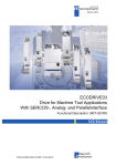
INSTALLATION, USE AND MAINTENANCE INSTRUCTIONS FOR PERMANENT MAGNET SYNCHRONOUS GENERATORS SWCn SERIES SICMEMOTORI electric machines are used in industrial environments. During functioning they can be a source of serious danger, both for persons and objects. They must therefore be installed correctly, commissioned and maintained and the protections/guards must not be removed or modified. These instructions cannot cover all possible problems and cases that may occur during use of the electric machines. SICMEMOTORI must be immediately informed of any problem that is not contemplated by these instructions. Code M-SWCn-E-11 INSTALLATION, USE AND MAINTENANCE INSTRUCTIONS FOR P.M. SYNCHRONOUS GENERATORS SWCn SERIES INDEX IMPORTANT NOTES SAFETY PROVISIONS 1. 1.1. 1.2. 1.3. 1.4. 1.5. 1.6. 1.7. 1.8. 1.9. 1.10. 1.11. 1.12. 1.13. 1.14. GENERALITIES Applicability and Reference Regulations Identification of the Manufacturer and the machine Declaration of Conformity Use and preservation of this manual. Limits of use Assistance networks Sicmeservice Liability of the Manufacturer Warranty Conditions Important warnings Limits of Use Machine noise Transport, receipt and handling the machine Storing the machine General description 2. 2.1 INSTALLATION Installation and positioning of the machine 3. 3.1 3.2 MECHANICAL COUPLING Direct coupling Direct coupling with the wind turbine blades 4. 4.1 4.2 4.3 4.4 4.5 4.6 4.7 4.8 COMMISSIONING Electric connections Earth connection Inspection before start-up Inspection after start-up Connection wiring diagrams Normal shutdown operations Emergency stop operations Accessories 5. 5.1 5.2 5.3 5.4 5.5 5.6 5.7 5.8 5.9 5.10 5.11 5.12 MAINTENANCE Periodical checks Roller bearings Useful life of the bearings Inspection of the bearings Types of bearings and loads accepted Lubrication programmes Lubrication – Specific instructions Complete replacement of the grease Bearing replacement Impulse generator encoder) Parking brakes Earthing brushes 6. 6.1 6.2 6.3 6.4 6.5 DISASSEMBLY AND REASSEMBLY OF THE MACHINE Disassembly and re-assembly operations of machines with permanent magnets Disassembly operations Bearing replacement Reassembly of the machine Moving the terminal box 7. 7.1 7.2 TROUBLESHOOTING Mechanical faults Electrical faults 8. INSTRUCTIONS FOR ELECTRICAL REPAIRS 9. WASTE DISPOSAL 10. SUPPLY ONLY OF THE STATOR + ROTOR KIT USER COMMENTS REGARDING THIS MANUAL Sicme Motori – Strada del Francese 130 – 10156 Torino – Italy M-SWCn-E-11 Tel. +39-011-4076311 - Fax +39-011-4500047 – www.sicmemotori.com – [email protected] Page 2 of 24 INSTALLATION, USE AND MAINTENANCE INSTRUCTIONS FOR P.M. SYNCHRONOUS GENERATORS SWCn SERIES IMPORTANT NOTES In order to highlight all of the dangers for the operator using the electric rotating machine, the various operations or situations will be written in bold type and/or with successive warnings, depending on their degree of hazard: DANGER! Operations and/or situations that can lead to serious physical injury, even death, if the instructions given are not followed scrupulously. ALARM! Operations and/or situations that must be scrupulously followed in order to prevent serious injury to persons and/or damage to the surrounding environment. Caution! Operations and/or situations that must be scrupulously followed in order to prevent injury to persons, contamination of the surrounding environment and material damage. Attention! Operations and/or situations that require particular attention. SAFETY PROVISIONS High voltages and rotating parts can cause serious injury and/or fatal wounds. The use of electric machines can therefore be very dangerous. Installation, functioning and maintenance of electric machines must be carried out by qualified staff, in agreement with applicable rules and with the Regulations in force in the various countries. For the electric machines subject of this manual, it is important to comply with the safety provisions in order to protect staff from possible injury. In particular, the staff must be informed to: • avoid contact with live circuits or rotating parts; • not by-pass or make safety circuits or barriers non-operational; • Move the electrical machinery by using both lifting eyebolts, paying attention to the angle between the lifting ropes; • use all precautions and procedures during movement, lifting, functioning and maintenance of the plant. The electric machines must be transported, commissioned, maintained and repaired exclusively by qualified staff, with the supervision of an expert that checks the correctness of these operations. The qualified staff must be appropriately authorised by the safety manager of the company where the machines are installed. Regarding this point, the International IEC364 Regulations prohibit use by unqualified staff when the machine is live. Before starting any maintenance interventions, check that: • The absence of accidental mechanical rotations is assured; in this case the electric machines with permanent magnets can also generate dangerous voltages; • The machine windings have been disconnected from the electric power supply and that accidental power supply is not possible; • All accessory devices associated to machine functioning in the work area have been disconnected from their power supply; Failure to comply with earthing the machine can cause death. Machine and plant earthing must be carried out in compliance with the regulations in force in the various countries. Any modification of the machine must be expressly authorised in writing by SICMEMOTORI. Only use indicated materials (sealers, oils, greases, solvents, etc.). Sicme Motori – Strada del Francese 130 – 10156 Torino – Italy Tel. +39-011-4076311 - Fax +39-011-4500047 – www.sicmemotori.com – [email protected] M-SWCn-E-11 Page 3 of 24 INSTALLATION, USE AND MAINTENANCE INSTRUCTIONS FOR P.M. SYNCHRONOUS GENERATORS SWCn SERIES 1. GENERALITIES 1.1 Applicability and Reference Regulations These instructions are applied to permanent magnet synchronous generators SWCn Series manufactured by SICMEMOTORI. This manual is drawn up in compliance with the 2006/42/CE Machinery Directive and UNI EN292-1 and 292-2 Standards. 1.2 Identification of the Manufacturer and the machine Every machine produced by SICMEMOTORI has an identification plate realised in conformity with IEC 60034-8 Regulations, as shown in the following figure. Every machine has CE marking. Meaning of the symbols: Type N° nn Pn Mn Hz V∆ V In ∆ In I0 ∆ I0 IP I cl V cl Induct. Resist. Slip Cos ϕ nmax Wgt IM DE brg NDE brg Fan Encoder Brake Type of generator Serial number Nominal speed Nominal power Nominal torque Nominal frequency Nominal voltage (delta) Nominal voltage (star) Nominal current (delta) Nominal current (star) No-load current (delta) No-load current (star) Level of protection Class of insulation Class of balancing Inductance of the windings Windings resistance Full load slip Power factor Maximum speed allowed Weight of motor Construction form DE bearing NDE bearing Type of electric fan and features Type of encoder and features Type of brake and features 1.3 Declaration of Conformity The SWCn Series generators described in this instruction satisfy the essential requisites of the following Directives: 2006/95/CE Reference has also been made to the following directives, specifically for the reasons listed as follows: EMC 2004/108/CE (Electromagnetic Compatibility) Directive 2006/42/CE Machinery Directive The electric generators are components that are incorporated into systems and plants and therefore the resulting EMC behaviour is under the responsibility of the Manufacturer of the plant incorporating the generator. Sicme Motori – Strada del Francese 130 – 10156 Torino – Italy Tel. +39-011-4076311 - Fax +39-011-4500047 – www.sicmemotori.com – [email protected] M-SWCn-E-11 Page 4 of 24 INSTALLATION, USE AND MAINTENANCE INSTRUCTIONS FOR P.M. SYNCHRONOUS GENERATORS SWCn SERIES With reference to the 2006/42/EC Directive, it must be specified that the generators must be installed in compliance with the installation instructions and cannot be put into service until the machine in which they are incorporated has been declared in compliance with the 2006/42/EC Machinery Directive. 1.4 Use and preservation of this manual. Limits of use This manual has been realised in order to make the use of this product easy and safe for the operator. The operator must be: Expert in the use of products destined exclusively to industrial and professional use; Informed regarding the dangers that can occur through the use of electric rotating machines for power supply voltages up to 1000 V. SICMEMOTORI is available, on specific written request, to provide training for the Client’s staff (or final user) regarding the correct use and maintenance of the products, both at the installation site and at the SICMEMOTORI establishment. For further information contact SICMESERVICE (see 1.6). This manual must always be available to the staff using the generators and a copy must be kept (by the user) for future reference. Other copies and updates can be requested directly from: SICME MOTORI srl Strada del Francese 130 10156 Torino – Italia tel. 011-4076311 fax 011-4500047 e-mail: [email protected] or they can be downloaded from the SICMEMOTORI web site www.sicmemotori.com SICMEMOTORI reserves the right to make any necessary variations to this manual, without updating any previous manuals. 1.5 Assistance networks SICMEMOTORI has created a capillary network of authorised workshops for assistance and repairs in the main Countries of the World, which the User can contact if necessary. The list of these workshops, which is constantly updated, is published on the SICMEMOTORI web site www.sicmemotori.com, and can be easily downloaded. 1.6 SICMESERVICE SICMESERVICE offers itself for maintenance services which enclose all electric generators. The services offered are: Preventive maintenance Preventive maintenance allows to evaluate the generators and to plan any precautionary maintenance on occasion of programmed plant standstill. Precautionary maintenance The precautionary maintenance is carried out at SICMEMOTORI workshops, and consists in a series of services that restore the original state of the generators. Extraordinary maintenance Allows to highlight the necessity for more resolutory interventions. The SICMEMOTORI technical offices can carry out an exact evaluation of that necessary for the restoration of complete functionality. In the case of uneconomical repair, the technical office can carry out correct dimensioning for the replacement of any type of generator of any mark with one more technologically advanced. For information regarding the service, contact: Mr. Andrea Dolfi Tel. +39-011-4076464 Fax +39-011-4500047 Cell. +39-348-2716623 e-mail: [email protected] 1.7 Liability of the Manufacturer SICMEMOTORI assumes liability for injury to persons or damage to objects attributed to defective products by accordance with the Italian law Presidential Decree 224 dated 24-05-1988 (implementing the EEC Directive 85/374) and any successive variants, on condition that they are known and in force at the time of placing the order, with essential specification that the liability is forfeited if it results that the provisions of these instructions have not been respected or if the products have been tampered with, for repairs or any other causes, by third parties that are not explicitly authorised in writing by SICMEMOTORI. 1.8 Warranty conditions SICMEMOTORI guarantees its products for 12 months from the date of delivery. The warranty exclusively concerns manufacturing defects ascribable to SICMEMOTORI, which may decide to replace or repair the defective product or the piece as seen fit. The cost and the risk of transport of the faulty product from the Client to SICMEMOTORI are the responsibility of the former. The warranty is voided in the case of tampering or interventions that are not authorised by SICMEMOTORI and does not extend to parts of the product that are normally subject to wear (e.g.: bearings, pulleys, pads, brakes). The warranty also becomes void in the case of failure to comply with the provisions indicated in the INSTALLATION, USE AND MAINTENANCE INSTRUCTIONS, available to the Client on request, an extract of which is contained inside the terminal boxes of all machines supplied by SICMEMOTORI. If a part must be Sicme Motori – Strada del Francese 130 – 10156 Torino – Italy Tel. +39-011-4076311 - Fax +39-011-4500047 – www.sicmemotori.com – [email protected] M-SWCn-E-11 Page 5 of 24 INSTALLATION, USE AND MAINTENANCE INSTRUCTIONS FOR P.M. SYNCHRONOUS GENERATORS SWCn SERIES replaced or repaired, the warranty is renewed solely for that part. The Client cannot withhold payment to SICMEMOTORI on the grounds that the warranty is not satisfactory. However, the Client forfeits the warranty whenever he omits the relative complaint for the purpose and effects of art. 1495 1st paragraph of the Civil Code. 1.9 Important warnings For correct use of generators manufactured by SICMEMOTORI the following warnings must be kept in mind: Planning and construction. They are carried out in compliance with IEC 60034 Standard, according to table a) indicated below: Title EN 60034-1 60034-1 Rating and performances EN 60034-2 60034-2 Methods for detemining losses and efficiency EN 60034-5 60034-5 Classification of the degrees of protection (IP code) EN 60034-6 60034-6 Methods of cooling (IC code) EN 60034-7 60034-7 Types of construction, mounting arrangements and terminal box position (IM code) EN 60034-8 60034-8 Terminal markings and direction of rotation Noise limits EN 60034-9 60034-9 EN 60034-14 60034-14 72-1 72-1 Dimensions and outputs for rotating machines 1293 Marking of electrical devices 16-8 IEC 60034-17 UNI ISO 2768/1-2 UNI 321 73/23/EEC 89/336/EEC (EMC) 2006/42/CE Mechanical vibrations of rotating machines Cage induction motors when fed from converter –Application guide General tolerances Shaft end Low voltage directive Electromagnetic compatibility directive Machine directive Tests. All generators manufactured by SICMEMOTORI undergo a complete inspection at the Company Test room, where compliance with contractual requisites is verified. Quality assurance. The entire production procedure is managed by the internal Quality Assurance System, which is responsible for the correct compliance to the procedures and construction, control, test and inspection instructions issued by the internal Quality System. The internal Quality System is certified and controlled by the QCS (*) in compliance with ISO 9001-2000 European Standards. (*) The Quality Certification System QCS is managed by the IMQ in collaboration with CESI, and is part of the CISQ (Italian Quality System Certification) and adheres to the international EQNET agreement. 1.10 Limits of use The SWCn generators have been manufactured by SICMEMOTORI as a direct coupling system for generation plants, thinking most of all about renewable sources such as water and wind. No other application of the electrical machine is possible without written authorisation from SICMEMOTORI. Installation environment. The generator is generally envisioned to work in dry, clean environments. The presence of high humidity and/or agents or aggressive powders in the atmosphere, must be communicated when placing the order; the mounting arrangement to be adopted in order to obtain acceptable functioning in these conditions must be agreed upon and indicated in the order confirmation. Finally, the generator is designed, unless different agreements are made with the Client, for environmental temperatures of –15 +40°C: Different temperature or installation, height conditions, normally lead to variations for the nominal performance values (contact SICMEMOTORI). See point 1.12 for lifting problems when the environmental temperature is very low. Connections. Generators must be connected to the electric grid through a suitable frequency converter. Performances. The generator supplies the contractual performances (power, voltage, current) at its terminals, under nominal torque and nominal speed values, as stated on the name plate. Incorrect conditions can lead to the impossibility to supply the contractual performances or to faults due to breakdown or intervention of the protections. Protections. Generator must be permanently protected against unacceptable load situations and against the occurrence of breakdowns. The lack of or incorrect calibration or inefficiency of the necessary protections consequently exclude SICMEMOTORI from any liability in the case of faults or breakdown. a) Electrical protections Generators are normally supplied with some protections of an electrical nature, which must be connected and whose functioning must be verified before the machine is commissioned. Generators must also be earthed before being commissioned (see par. 4.2). b) Mechanical protections Before commissioning the generator, the User must check that all mechanical protections on the generator are operational. In particular, the generator must not be used if: − The generator has not been adequately fixed to its supports (see par.2.1); Sicme Motori – Strada del Francese 130 – 10156 Torino – Italy Tel. +39-011-4076311 - Fax +39-011-4500047 – www.sicmemotori.com – [email protected] M-SWCn-E-11 Page 6 of 24 INSTALLATION, USE AND MAINTENANCE INSTRUCTIONS FOR P.M. SYNCHRONOUS GENERATORS SWCn SERIES - The main terminal box lid (and auxiliaries if existing) has not been closed correctly using its screws, in order to prevent accidental contact with live parts; As well as the mechanical protections inherent to the generator, the User must also check that all components coupled to the generator itself and in movement (any ropes, pulleys, etc.) are adequately protected from accidental contact. C Protection from heat risk During functioning the external surfaces of the generator can reach very high values (heat risk). For this reason, warning plates are applied to the generators surfaces themselves indicating this risk. The User must place protective barriers around the generator if it is installed in areas with the risk of even accidental contact with the operators. 1.11 Generators noise The noise of the generator expressed in “sound pressure” is detected using a sound level meter in empty functioning, with nominal power supply (IEC Regulation 34-9). The sound level meter is positioned at the centre of the 4 sides of the generator being tested at a distance of about 1 m. The average value among those obtained is the noise level adopted by SICMEMOTORI. The noise value of the generator is stated among the technical data. 1.12 Transport, receipt and handling of the generator When moving the generator it must be lifted by using both the 2 special eyebolts found in the top part of the generator housing, paying attention that the angle between the lifting ropes will not be <45°. Lifting must be avoided when the environmental temperature is below –15°C . 1.13 Storing the generator If the generator is not used immediately, it must be stored in a covered, clean, dry environment. The minimum storage temperature must not be lower than –30°C . If the generator must be stored at temperatures lower than –30°C, agreements must be made with SICMEMOTORI on placing the order. 1.14 General description The main features of SWCn series generators are: 1. Direct coupling (without reducer, even if obviously this is not obligatory) 2. Ripple torque and magnetic sticking torque very reduced thanks to a specific design 3. Complete and very compact unit (smaller installation space) 4. Electro-magnetic brake for integrated parking, optional 5. Integrated encoder, optional The three-phase synchronous generator with permanent magnets was designed using direct coupling principles (direct-drive), in order to obtain high torque and reduced size. The Neodymium-Iron-Boron type permanent magnets have been accurately selected in order to obtain: • Constance of the magnetic features through time; • Resistance to high temperatures; • Strength; • Resistance to corrosion. The windings, manufactured with insulated wire and soaked with adequate resin, adapt for inverter duty, are housed in the stator and appropriately isolated. The electric circuits are protected from overheating by means of heat pads that are relevantly inserted into the stator windings. In the case of transmission by rope or belt, as in the case of high strains transmitted from the primary motor to the generator in an axial direction, a different design must be envisioned that is different from the standard one and this data must be communicated to SICME MOTORI in the offer request phase. SICME MOTORI has no responsibility relative to damage caused due to high radial or axial loads that was not previously communicated. SICMEMOTORI pays particular attention to the mechanical capacities of its generators, planning them with the aid of the la test software simulation. Another very important aspect of these generators is the minimisation of vibrations linked to the magnetic sticking and the excellence and linearity of the electromagnetic phenomena inside the rotating electrical machine. SICMEMOTORI has exploited its many years of experience in the planning and production of electric machines, designing a permanent magnet synchronous generator, which is excellent from this point of view. The rate of performance of the empty load and loaded torque were checked in the prototype phase to guarantee maximum performance. Incorrect mechanical installation can therefore cause vibrations due to the entirety of the mechanical system; therefore it is necessary to follow the installation rules stated in this installation, user and maintenance manual along with a good code of practice regarding mechanical installations. Sicme Motori – Strada del Francese 130 – 10156 Torino – Italy Tel. +39-011-4076311 - Fax +39-011-4500047 – www.sicmemotori.com – [email protected] M-SWCn-E-11 Page 7 of 24 INSTALLATION, USE AND MAINTENANCE INSTRUCTIONS FOR P.M. SYNCHRONOUS GENERATORS SWCn SERIES 2 INSTALLATION 2.1 Installation and positioning of the generator For generators with mounting arrangement IM 1001 (B3, horizontal axis with feet), fixing must be carried out using screws with an adequate diameter for the hole in the feet (see table). The rest surface must be level, with tolerance such that the maximum difference between the feet is not greater than 0.1 mm (if necessary, use alignment thickness). The fixing screws must be tightened with the fixing torques stated in the following table: Fixing screws Tightening torque (Nm) ** M20 480 M20 480 M20 480 M24 690 M24 690 For bigger screws please ask SICMESERVICE The fixing screws must be able to support the torque generated by the generators in the worst conditions (short circuit at the maximum working speed). The following formula gives the short circuit dynamic load value in N for every size of motor, necessary to calculate the foundations and relative anchorage. Short circuit dynamic load (*) : 5xTnom (*) on each support foot area. The strain of the compression load (+) or traction (-) is linked to the electro-dynamic reaction and depends on the direction of rotation. Caution! The machine base, whether it be in iron or cement grout, must be made by skilled personnel. Sicme Motori – Strada del Francese 130 – 10156 Torino – Italy Tel. +39-011-4076311 - Fax +39-011-4500047 – www.sicmemotori.com – [email protected] M-SWCn-E-11 Page 8 of 24 INSTALLATION, USE AND MAINTENANCE INSTRUCTIONS FOR P.M. SYNCHRONOUS GENERATORS SWCn SERIES 3. MECHANICAL COUPLING 3.1 Direct coupling The SW series generators manufactured by SICMEMOTORI are designed for direct coupling. Operate as follows to obtain efficient direct coupling. The use of flexible couplings is recommended as they prevent transmission of any axial thrust to the bearings Good alignment requires the use of a comparator and a feeler gauge for the following operations: • Mount the half coupling onto the generator, position the two machines aligning them roughly. Tighten the fixing screws. • Apply the comparator onto the two half-joints and measure radial alignment. Repeat the measurement after having turned the two shafts 45°, 90° and 180° together. • Introduce a feeler gauge between the faces of the half-joints and measure their distance. Repeat the measurement at 90°, 180°, 270°. • Correct the alignment errors met in the operations described by inserting thicknesses between the base and the fixing point. • Tighten the screw fasteners fully home with suitable dynamometric key, repeat the measurements and if alignment is accurate, apply the registration pins between the generator and the base. Remember that there must be sufficient play between the transmission components to allow axial dilation due to heating. It is however recommended to carry out coupling operations using new generation lasers if possible (contact SICMEMOTORI). The approximate tolerance values relative to coupling are shown below: Radial tolerance ∆r ≤ 0.1mm Angular axial tolerance ∆b ≤ 0.1mm Axial tolerance ∆a = 2-3mm 3.2 Direct coupling with the wind turbine blades Check the mounting system of the generator into the nacelle of the wind turbine, than call SICMESERVICE Sicme Motori – Strada del Francese 130 – 10156 Torino – Italy Tel. +39-011-4076311 - Fax +39-011-4500047 – www.sicmemotori.com – [email protected] M-SWCn-E-11 Page 9 of 24 INSTALLATION, USE AND MAINTENANCE INSTRUCTIONS FOR P.M. SYNCHRONOUS GENERATORS SWCn SERIES 4. COMMISSIONING 4.1 Electric connections All generators are normally supplied with terminal boxes complete with terminal boards. The cables are marked with the letters stated in the diagram attached to the generator. Alternatively, on Client request, it is possible to supply the generator with free cable output, whose terminals will be marked according to the same criteria. The terminals are marked according to IEC 60034-8 Standards. For the connections, make reference to the diagrams given with the generators, connecting the three generator phases according to the sequence indicated. The direction of rotation with connection of the phases in U,V,W or R,S,T sequence is normally clockwise. 4.2 Earth connection The generator must always be connected to the establishment’s earth plant. A screw in the terminal box, complete with a marking plate, is provided for grounding. Make sure that there is no paint between the screws and the surface of the generator. If necessary, remove the paint before carrying out the connection. Work can only be carried out on the generator if it is absolutely certain that the plant is in safe conditions, it is disconnected from the mains and all mechanical safeties to avoid the sudden rotation of the generator itself have been activated 4.3 Inspection before start-up Before commissioning the generator or after a long period of inactivity, it is a good idea to perform the following checks: • Use a 500 V Megger to control isolation towards the earth of the stator windings. The value detected must not be lower than 1,5MΏ for generators up to frame 280, or 7MΏ for bigger generators. The operation must be performed with the power supply cables disconnected. ALARM! During and immediately after measurement of the isolation resistance, the generator terminals are potentially dangerous and must not be touched. Check that there are no voltage residues before touching them. If the resistance value measured is lower, the causes and solutions could be the following: a) Presence of dust Non-greasy dust may be removed using a clean, dry cloth, or even better using a suction device. Repeat the isolation test. b) Presence of grease or oil Rub with a cloth and dielectric solvent (FC200 recommended). If the problem persists, wash the interested parts with suitable spray gun containing dielectric solvent (FC2000 recommended) – Aerosol. Dry on the air and check again the insulation. Repeat the isolation test before starting-up the motor. • Check that all accessories and/or protection devices have been correctly connected and function. DANGER! Before carrying out any interventions on the generator, secure all the area by activating all protection devices, to avoid the sudden rotation of the generator. Disconnect the generator from the mains by disconnecting any cable from the generator terminal box. The disk brakes installed (OPTIONAL) on the SWCn series generators are precision devices, whose functioning must be verified before final installation of the generator. It is advised to release the two brakes mechanically, by means of the relative release lever and manually check that the rotor can turn uniformly without sticking. If it is not possible to release the brakes mechanically due to the lack of an adequate device, the brakes can be powered in accordance with that prescribed in the manual (note: most of all following extended storage a condition may be created in which the friction at first detachment of the rotating part is quite high). 4.4 Inspection after start-up The maximum over-temperature accepted by IEC Standards is 105°C (insulation class F). Even they normally have much lower over-temperature values, our machines however require adequate protection against accidental contact. Moreover, never leave highly-inflammable materials in contact with functioning machines. The heat probes present on the generators must be monitored. 4.5 Connection wiring diagrams The generator cannot be connected to the mains without the positioning of a specific inverter for the application. The use of shielded three-phase cables is recommended for the connection between generator and inverter, with the shield connected on both sides, in order to prevent the propagation of electro-magnetic disturbances towards other electronic devices (any encoder, inverter). It is noted that the length of the cable between the inverter and generator must be as short as possible, in order to limit stress deriving from the voltage peaks that may form at the generator terminal board and that can lead to an appreciable shortening of its life. Sicme Motori – Strada del Francese 130 – 10156 Torino – Italy Tel. +39-011-4076311 - Fax +39-011-4500047 – www.sicmemotori.com – [email protected] M-SWCn-E-11 Page 10 of 24 INSTALLATION, USE AND MAINTENANCE INSTRUCTIONS FOR P.M. SYNCHRONOUS GENERATORS SWCn SERIES Therefore check that the voltage peaks and the voltage derived (∆V/∆t) at the generator terminals are within the limits set by the IEC 60034-17 Standard. They can be reduced using a reactor, a filter ∆V/∆t or a sinusoidal filter; it is necessary to consult the Manufacturer of the inverter. If not specifically stated the coupling torques of the terminal board nuts are the following: Nm (+/- 10%) M4 M5 M6 M8 M10 M12 M14 M16 1.2 2.4 4 8 12 20 30 40 The generator is thermally protected by means of 3 PTC thermistor probes, each inserted into a generator phase, in order to verify localised overheating caused by an unbalanced power supply. These probes are connected in series to each other, obtaining only two terminals. The pulse generator (encoder) installed on the generator (optional) must be correctly connected to the inverter. This connection is the installer’s responsibility. SICMEMOTORI is not liable for any damage caused by incorrect connection of the encoder. As the encoder is a device that can be damaged following electrostatic discharges, it is advised that the operator in charge of connecting the encoder discharges himself by touching a metal part connected to the circuit’s earth plant. If not differently specified in the order phase, the encoder is supplied with cable output and the installation technician must follow the instructions stated in its installation, user and maintenance manual, supplied by SICMEMOTORI. It is recommended always to check the correct preparation of the inverter, hardware and software, for the correct functioning of the position transducer and to proceed with the encoder signal timing operation according to that described in its installation, user and maintenance manual and the installation, user and maintenance manual of the inverter used. The correct mechanical fixing of the encoder is carried out by SICMEMOTORI in the final assembly phase and for this reason it is necessary to contact SICMEMOTORI whenever the encoder must be removed from its seat. Electric connections of the brakes (when existing): SICMEMOTORI supplies the installation, user and maintenance manual relative to the brakes installed (optional), to which reference must be made for the correct power supply of the brakes themselves. If the supply should not include a power supply device for the brakes, the installation technician should provide a suitable power supply circuit, in compliance with electrical standards regarding BT plants. SICMEMOTORI suggests the following layout for the power supply circuit, in the case of brakes that request initial over-excitement: notes: - trafo500VA - brakes coils at 104/207Vdc - brakes supply inparallel Notes: - Auxiliary circuit connexion diagram for both series and parallel brakes connection - Temp. set at 2-3 seconds approx For different connections, please get in touch with SICMESERVICE Sicme Motori – Strada del Francese 130 – 10156 Torino – Italy Tel. +39-011-4076311 - Fax +39-011-4500047 – www.sicmemotori.com – [email protected] M-SWCn-E-11 Page 11 of 24 INSTALLATION, USE AND MAINTENANCE INSTRUCTIONS FOR P.M. SYNCHRONOUS GENERATORS SWCn SERIES If the brakes should have different power supply voltages, the same circuits can be used, opportunely varying the power circuit. For example, for brakes to be powered at 50/100Vdc, it is possible to use the circuit illustrated, connecting the brakes in series, or for brakes to be powered at 24/48Vdc it would be a good idea to use a power supply transformer with secondary circuits at 60/110Vac and connect the brakes in series. It is however necessary to follow that stated in the specific installation, user and maintenance manual regarding the brakes, supplied by SICMEMOTORI. The components are indicated in the layout as an example only and SICMEMOTORI has no responsibility regarding incorrect functioning of the brake power supply circuit assembled by the installation technician. 4.6 Normal shutdown operations The electro-magnetic parking brake (optional) was designed to guarantee electrical braking that requires a torque no greater than the maximum torque specified in the technical data. The brakes are for parking and are not subject to wear during normal use. If there is a power cut, these brakes are practically powered at the same time as the generator and are un-powered when the null speed is reached (evidently, their activation must be controlled by an external device, e.g. a PLC). The relative delays between activation of the brakes and the un-powering of the generator and vice versa are at the discretion of the person using the generator, who must verify any standards relative to the generation plants and which are not the responsibility of SICMEMOTORI, who is not liable for the damage caused by an incorrect braking procedure. Most of all, the user must check that braking takes place after the generator has stopped, because if this condition is not respected, wear is caused and sudden deterioration of the brakes through time. 4.7 Emergency stop operations The parking brakes are not normally adapt for emergency braking at full generator torque. If ever they should be activated while the generator is in rotation, they could be reciprocally damaged. Even if there is no visible damage, successive start-up must only be carried out after the entire plant has been checked. 4.8 Accessories SICMEMOTORI can supply several accessories, which are agreed at the order phase and must appear on the order confirmation. Sicme Motori – Strada del Francese 130 – 10156 Torino – Italy Tel. +39-011-4076311 - Fax +39-011-4500047 – www.sicmemotori.com – [email protected] M-SWCn-E-11 Page 12 of 24 INSTALLATION, USE AND MAINTENANCE INSTRUCTIONS FOR P.M. SYNCHRONOUS GENERATORS SWCn SERIES 5. MAINTENANCE The SWCn series permanent magnet generators are practically maintenance free, apart from eventual greasing of the bearings. However, dedicated periodical checks with suitable instruments (after 20.000h working) are advised, in order to reduce possible failures to a minimum. After interruptions due to interventions of the protection devices or for any other reason, an in-depth inspection of the generator is necessary and if required, also of other plant components. The cause of the interruptions must be made clear BEFORE starting the generator/plant up again. DANGER! Before carrying out any interventions on the generator, secure all the area by activating all protection devices, to avoid the sudden rotation of the generator. Disconnect the generator from the mains by disconnecting any cable from the generator terminal box. 5.1 Periodical checks The table indicates a programme–type of periodical checks; it must be intended that this programme must be adapted to the Client’s requirements and that SICMEMOTORI is available for collaboration to study the most appropriate adaptations on commissioning and during the first working period. Component Complete generator Windings Power supply cables Bearings Insulation Fixing screws and bolts and electrical connections Operations Check the vibrations and noise on the bearing seats. ISO 3945 Standard reference values (a) Detection of any strange noises (blows, friction, etc.) (a) Visual check of cleanliness inside the machine Measure the insulation resistance (a) Check tightness of the cables at the motor clamps. Tighten them if necessary. Temperature measurement (a) (d) Re-lubrication and application of grease (excluding selflubricating bearings) (d) (e) (f) Check for presence of rust on bearings (c) Check insulation resistance value using the 500V Megger Check for loosening of all electrical connections of the terminal board and of fixing screws and bolts Check the state of machine-load alignment and record the measurement (b) Couplings Various accessories Earth brush (if present) Carry out maintenance of the coupling joint according to the instructions of the Manufacturer of the joint (h) Control their correct functionality Check that it runs freely in its brush-holder. Clean the contact surfaces between the brushes and shaft with very fine sand paper (a) Interval (H) See point annual 5.4 monthly 6 months yearly 4.3 annual 4.5 6 months See plate 5.9 3 years yearly 4.3 2 years 2.1 Every two years and at every disassembly 3 annual annual 5.13 * Humid environments (a) (b) (c) (d) (e) Compare with previous measurements and observations If the vibrations increase, inspect immediately or shorten the intervals between inspections Remove any rust. For bearings lubricated with grease Comply with the lubrication intervals indicated on the generator’s name plate . Generators that are at a standstill for long periods of time require re-lubrication at least once a year (as the grease may age or condensation may be formed inside the bearing) (f) As soon as vibrations, over-temperatures or noises occur or, when required, the generator must be disassembled. Experience tells us that problems with bearings are mainly caused due to wear, rather than material fatigue. However, consumption also depends on functioning conditions. (g) Only blow the windings if the generator is open. (h) Attention! Before checking the wear of the brakes and any joint or pulley: 1. Stop all mechanical parts and fix them using the relative supports 2. Assure that the generator, if disconnected mechanically from the blades, cannot rotate, as it could generate dangerous voltages 3. Open the electric power circuits and assure that they cannot be closed during maintenance. Particular instructions are given below for maintenance relative to bearings and brakes. Sicme Motori – Strada del Francese 130 – 10156 Torino – Italy Tel. +39-011-4076311 - Fax +39-011-4500047 – www.sicmemotori.com – [email protected] M-SWCn-E-11 Page 13 of 24 INSTALLATION, USE AND MAINTENANCE INSTRUCTIONS FOR P.M. SYNCHRONOUS GENERATORS SWCn SERIES 5.2 Bearings In the following paragraphs DE means driving end and NDE means non driving end. Generators in this range are normally envisioned with ball bearings. The type of bearing is indicated on the generator name plate. In the case of inconsistency, the information on the plate is to be considered valid. 5.3 Useful life of the bearings SICMEMOTORI selects the bearings used on the basis of supplier catalogue data and the type of coupling, and forecasts a minimum theoretical life of 100,000 hours. The theoretical life is calculated in normal working conditions, i.e. for normal service (continuous service with load lower than or equal to the nominal load, without sudden overloads or inversions of direction) with normal direct coupling by means of flexible (see point 5.5), in normal environments (without vibrations or blows, dry, clean, with maximum environmental temperature of 40°C). The theoretical life cannot be subject to warranty (as it is a statistic value that cannot be used without caution in the individual case) and is transmitted by SICMEMOTORI to the Client on the basis of the information received from the supplier. The effective useful life of the bearing depends largely on the service and the more or less efficient maintenance. The establishment of a reasonable value of the effective useful life, to be considered for a programmed maintenance plan, is entrusted to the user’s Maintenance Service and must be based on the constant and systematic control of the machine. 5.4 Inspection of the bearings The inspections must be subject to a precise programmed maintenance plan, with the scope of keeping the following under control: • Over-temperature, which must never exceed 80°C in normal working conditions. A higher over-temperature generally denotes a deterioration of the coupling conditions with unacceptable radial or axial stress; • Noise. No blows should be heard. Any blows are a symptom of deterioration of one or more rolling elements. On the appearance of strange noises, the state of the bearing must be checked carefully (wear of the tracks, consumption of the cage, play between the external ring and seat, external thrust, etc.) with the generator at a standstill and disassembled. If the mentioned phenomenon should worsen or at the first suspicion of a fault regarding the bearing, immediate replacement must be programmed, to prevent the danger of serious damage to the generator. 5.5 Types of bearings and loads accepted The types of bearings used on the SWCn series generators are stated on the generator’s name plate. The SWCn series electric generators should not have radial or axial loads in normal functioning conditions. It is however possible to discuss the necessity to mount specific types of bearings instead of the standard types. Attention: please check always the type of bearings marked on the generator name plate; in case of doubt please ask SICMEMOTORI. 5.6 Lubrication programmes A periodical lubrication plan for the bearings must be previously established by the Client’s Maintenance Service for every generator. For the bearings that require lubrication, plates are applied in proximity of the bearings that indicate the quantity of grease necessary and the lubrication intervals. It is highly recommended to follow the indicated amounts scrupulously: an excessive quantity can lead to breakdown. 5.7 Lubrication – Specific instructions This operation must be carried out with the generator running. Apply the pump to the greasing nipple and remove the grease outlet plug to allow the oil coming from the deteriorated grease to flow out. Add the amount of grease envisioned on the generator name plate. Remove the pump and re-position the plug. The positions of the greasing nipple and the outlet plug are indicated by relevant plates. Attention! Do not apply an excessive amount of grease. Excess grease overheats the bearings and can damage them. The excess grease tends to escape along the shaft. Do not mix different types of grease as they could be incompatible. In normal conditions (in particular with environmental temperatures that do not exceed 40°C) the greas e to be used must have the following features: • Soap-base: lithium or polyurea • Drop point: 180-190°C o • Consistency: N 3 NLGI with penetration values between 220 and 250 tenths of mm; • Working temperature: -25 to +120°C. Table 5.a shows some types of grease used in normal conditions. For use in difficult conditions (and particularly when environmental temperature exceeds 50°C) special greases with high thermal stab ility must be used, which have the following features: • Organic base: urea or complex calcium salts; • Drop point: 220-250°C; • Consistency a: with penetration values between 240 and 270 tenths of mm; • Working temperature: -30 to +150°C. Table 5.b some types of grease for difficult conditions. Product name Supplier Athesia Gr3 IP Mobilux 3 Mobil Exxon Beacon Exxon Alvania 3 Shell Table 5.a – Some types of grease used in normal conditions Sicme Motori – Strada del Francese 130 – 10156 Torino – Italy Tel. +39-011-4076311 - Fax +39-011-4500047 – www.sicmemotori.com – [email protected] M-SWCn-E-11 Page 14 of 24 INSTALLATION, USE AND MAINTENANCE INSTRUCTIONS FOR P.M. SYNCHRONOUS GENERATORS SWCn SERIES Product name Supplier SRI 2 Chevron Mobilplex 48 Mobil Aeroshell 12 Shell Table 5.b – Some types of grease for difficult conditions 5.8 Complete replacement of the grease Must be carried out by qualified staff and in a well equipped workshop. Protect the electric windings during the operation. For indications and procedures, please contact SICMESERVICE. 5.9 Bearing replacement This must be envisioned in function of the values measured during the checking operations. Please contact SICMESERVICE. 5.10 Pulse generator (encoder), optional Whenever the generator is supplied complete with encoder, refer to its installation, use and maintenance manual, supplied by SICMEMOTORI. The Pulse generator is accessible from the rear side of the generator. The assembly and/or connection of the encoder must be performed by qualified staff. If in doubt, consult SICMESERVICE. ATTENTION: before mounting and/or connecting the encoder read the following instructions carefully. The warranty is forfeited immediately if the instructions are not respected or if the encoder is tampered with and/or repaired by unauthorised staff. Operations that must NOT be performed regarding the impulse generator: MECHANICAL DO NOT disassemble the encoder, in order not to lose the warranty; repairs are only accepted under warranty for appliances sent to SicmeMotori DO NOT carry out any work on the shaft; this can cause the disk to break, deterioration of the bearings and loss of warranty DO NOT exert abnormal pressure, flexions and torsions onto the shaft of the instrument. DO NOT assemble differently to that envisioned. ELECTRICAL DO NOT use power supply sources with an auto-transformer that does not assure galvanic isolation of the power supply network. All inverters normally have a dedicated encoder power supply. Refer to the relative installation, use and maintenance manual. DO NOT allow the cable to run near to and/or parallel to the high voltage power supply line or join the cables in the same channel. This precaution must e complied with scrupulously in order to prevent malfunctioning due to inductive interference. DO NOT use longer cables than necessary. Try and keep the length of the cable as short as possible, in order to prevent the influence of disturbances of an electrical nature. DO NOT carry out connections if there are doubts regarding them (see connection diagram on the instrument’s label). Incorrect connections can cause faults to the internal circuits of the instrument. DO NOT connect the instrument’s shielded cable to a 0 Volt circuit The cable shield MUST BE connected to earth (GND). DO NOT leave it disconnected! The shield must be connected to earth only from the generator power supply side; in some cases, depending on the type of plant, the shield may have to be connected both from the power supply side and on the instrument side female connector. 5.11 Parking brakes, optional Check and calibrate the brakes according to that described in the relative installation, user and maintenance manual. 5.12 Earthing brush If rotor earthing brushes are present, check their functionality periodically (wear, contact with the rotor). Replace them if necessary. Sicme Motori – Strada del Francese 130 – 10156 Torino – Italy Tel. +39-011-4076311 - Fax +39-011-4500047 – www.sicmemotori.com – [email protected] M-SWCn-E-11 Page 15 of 24 INSTALLATION, USE AND MAINTENANCE INSTRUCTIONS FOR P.M. SYNCHRONOUS GENERATORS SWCn SERIES 6. DISASSEMBLY AND RE-ASSEMBLY OF THE MACHINE DANGER! Before carrying out any interventions on the generator, secure all the area by activating all protection devices, to avoid the sudden rotation of the generator. Disconnect the generator from the mains by disconnecting any cable from the generator terminal box. 6.1 Disassembly and re-assembly operations of permanent magnet machines The disassembly and re-assembly operations of the permanent magnet electric machines present particular difficulties and risks owing to the presence of these permanent magnets on the rotor which, generate forces of attraction between the rotor and other iron parts even if the machine is not powered. Therefore, these operations must be carried out by expert staff with knowledge of the machine. 6.2 Disassembly Disconnect the generator from all electric cables Extract the coupling half-coupling using a relevant tool when cold, if the end of the shaft has the key or refer to the manufacturer’s instructions regarding the transmission component if the end of the shaft is smooth. Remove the encoder and/or other accessories. For disassembly of the brakes, refer to their installation, use and maintenance manual. Proceed as follows to disassemble the electric machine: 1 Select the sectional drawing from the following pages containing the nomenclature of the components and check that it corresponds to the type of generator where maintenance is to be performed. 2 Remove the generator from the plant. 3 Mark and remove the transmission component using a suitable instrument avoiding blows that would damage the bearings and any accessories (transducers brakes, etc.). 4 Loosen and remove the screw fasteners on the base of the transducer connector, if installed. 5 Loosen and remove the screws from the transducer cover, if installed 6 Mark and remove the transducer cover. 7 Remove the transducer, marking the position and being very careful. 8 Loosen and remove the DE and NDE shield screw fasteners. 9 Loosen and remove any screws positioned on the DE and NDE used to block the bearings. 10 Extract the key from the DE shaft and also any sealing rings. 11 Slide the DE cover complete with rotor out of the front part of the generator paying attention not to damage the windings. This operation is particularly delicate because the rotor magnets tend to strongly accentuate every misalignment between the rotor and the stator and eventually attach the rotor to the internal surface of the stator, risking damage to the magnets and, when the rotor is at least partially extracted, to the windings. It is advised to previously introduce sheets of non-magnetic material between the rotor and the stator (e.g. brass) and thicknesses measuring 0.2-0.5mm in order to prevent contact between the rotor and stator, and in case of contact, decrease friction between the two surfaces. 12 Mark and extract any elevation thickness. 13 Proceed with the controls and cleaning of the windings, if necessary. 14 Re-assemble following the procedure in the opposite direction. 15 Check that the generator is not to earth and there are no short circuits in the windings. 16 Try the generator possibly with reduced voltage following the regulations described above regarding the protections and safety. IMPORTANT: If the generator must be rewound, contact the Manufacturer before proceeding. The instructions and drawings may not coincide perfectly with the effective construction of the motor. In case of particular accessories and special executions please contact SICMESERVICE. For generators complete with position and/or speed transducers it is also necessary to follow that stated in their installation, use and maintenance manual. For generators complete with brake it is also necessary to follow that stated in their installation, use and maintenance manual. Follow that indicated in paragraph 6.3 to replace the bearings. We strongly recommend to ask SICMESERVICE BEFORE any kind of operation to disassemble the generator or to replace the bearings! Sicme Motori – Strada del Francese 130 – 10156 Torino – Italy Tel. +39-011-4076311 - Fax +39-011-4500047 – www.sicmemotori.com – [email protected] M-SWCn-E-11 Page 16 of 24 INSTALLATION, USE AND MAINTENANCE INSTRUCTIONS FOR P.M. SYNCHRONOUS GENERATORS SWCn SERIES 6.3 Bearing replacement We strongly recommend to ask SICMESERVICE BEFORE any kind of operation to replace the bearings! The disassembly and assembly of bearings must always be carried out carefully, paying particular attention not to ruin the bearings seat on the shaft. The used bearings are removed using a relevant extractor. The new bearings must be the same as those removed: Particular attention to the play (check the indications on the machine plate). Any deformation of bearing housings must be eliminated throughout suitable mechanical operations BEFORE the replacement of the bearing. In case of roller bearing NJ series, please check the position of the inner ring BEFORE bearing disassembly. Interpose between the extractor scriew (draw bolt) and the shaft a suitable protection plate. Proceed as follows to mount new bearings: Clean the bearings, the relative flush on seats and the internal grease-guard chamber carefully. Heat the bearing to 80 -100°C by induction, placing it in an oven or in an oil bath. Flush it onto the shaft and hold it against the thrust block for 60-90 seconds. Eliminate the pressure applied and check the internal ring does not turn on the shaft. With reference to the types of grease to be used refer to tables 5.a – 5.b in point 5.7. 6.4 Re-assembly of the generator Proceed in the opposite way to disassembly. 6.5 Moving the terminal box When particular installation requirements make it necessary to position the terminal box on a different side to that initially forecasted (operation possible on some generator only), the operation must be carried out by qualified staff. Please contact SICMESERVICE for information. Sicme Motori – Strada del Francese 130 – 10156 Torino – Italy Tel. +39-011-4076311 - Fax +39-011-4500047 – www.sicmemotori.com – [email protected] M-SWCn-E-11 Page 17 of 24 INSTALLATION, USE AND MAINTENANCE INSTRUCTIONS FOR P.M. SYNCHRONOUS GENERATORS SWCn SERIES 7. TROUBLESHOOTING If abnormal phenomenon should occur during working or start-up of the generator, the cause must be immediately searched for and eliminated. Some probable anomalies, their cause and solutions are examined below (note: reference is made to the electric machine with the term “motor” instead of “generator” as the phenomena described are common to all electric machines, independently of their use). For phenomenon not mentioned in the tables or not well-identified, please contact SICMEMOTORI. DANGER! Before carrying out any interventions on the generator, secure all the area by activating all protection devices, to avoid the sudden rotation of the generator. Disconnect the generator from the mains by disconnecting any cable from the generator terminal box. 7.1 Mechanical faults Anomaly Possible causes Faulty bearings Vibrations in uncoupled machine Vibrations in coupled machine Anomalous heating of the bearings immediately after start-up or greasing Anomalous heating of the bearing after a long functioning period Solutions Replace the bearings Check balancing Unbalanced rotor Balance the machine with Unbalanced half-joint half-joint Foundation bolts loosened Tighten and block bolts Machine coupled or unbalance joint Check balance Alignment fault Check coupling Faulty bearings Check the bearings Check activation, control, Inverter badly calibrated or fault in the commanded machine coupled machine and alignment Motor foundation bolts or alignment Tighten and block bolts components loosened Check and replace the Faulty speed transducer speed transducer if required Excessive amount of grease Remove the excess grease Excessive axial load Check axial load Tel. +39-011-4076311 - Fax +39-011-4500047 – www.sicmemotori.com – [email protected] 5.4 2.1 5.4 3 5.4 4 2.1 5.11 5.5 Ovalized bearings seats Disassemble the bearing for Friction of the grease-guard of the maintenance or replacing bearing on the shaft Not enough grease Grease Whistling at the bearings, Faulty bearing Replace the bearing noisy bearings Leave the machine to work Noisy cage under tight control Excessive bearing Reduce radial load, Excessive load on bearing consumption eliminate axial load Bearing track marked, with Stop the machine and Bearings passed by Eddy-currents machine in service (burns) contact SICMEMOTORI Noise and vibrations coming from the brake (if Air gap too big, brake not powered Check the air gap and brake present), generator has correctly power supply difficulty reaching max. speed Long braking, little braking Check if it is necessary to torque, noises and Wear of friction material replace worn components vibrations** Sicme Motori – Strada del Francese 130 – 10156 Torino – Italy See point 6.3 6.3 5.7 – 5.8 6.3 5.5 4.5 – 5.12 5.12 M-SWCn-E-11 Page 18 of 24 INSTALLATION, USE AND MAINTENANCE INSTRUCTIONS FOR P.M. SYNCHRONOUS GENERATORS SWCn SERIES 7.2 Electrical faults Anomaly Possible causes Solutions Excessive overload Check voltage and current Inverter broken or incorrectly Check phase absorption check calibrated inverter functionality Excessive heating Check the transducer and replace Transducer not functioning (heat probe it if necessary intervention) Environmental temperature Suspend the service. Consult too high SICMEMOTORI Release the brake (check the Brake not released* power supply) Insufficient or incorrect power Check transducer power supply supply Transducer functioning Anomalous connections or Check the connections incorrectly with false contacts Transducer electrical data not Replace the transducer compatible with the inverter Condensation, humidity, Clean the motor; take in cooling air water, oil, oil vapours, present from a clean environment. Low insulation inside the motor resistance Rewind the motor. Insulation deteriorated Consult SICMESERVICE Condensation, humidity, Clean the motor; take in cooling air water, oil, oil vapours, present from a clean environment. If this is inside the motor not enough, consult contamination from chemical SICMESERVICE agents Excessive windings Check functioning parameters. temperature Consult SICMESERVICE Generator to earth or in Check alignment to the load; check short circuit the base; check any vibrations Excessive vibrations coming from the controlled machine, check the power supply. Consult SICMESERVICE Insulation in hollow or of the Rewind the motor. wire deteriorated or damaged Consult SICMESERVICE mechanically Overheating of cables Stop the generator and check the Connection screws loosening connections connections at the terminal box Sicme Motori – Strada del Francese 130 – 10156 Torino – Italy Tel. +39-011-4076311 - Fax +39-011-4500047 – www.sicmemotori.com – [email protected] See point 4.1 5.11 5.12 5.11 4.1 5.11 4.3 2 2 M-SWCn-E-11 Page 19 of 24 INSTALLATION, USE AND MAINTENANCE INSTRUCTIONS FOR P.M. SYNCHRONOUS GENERATORS SWCn SERIES 8. ISTRUCTIONS FOR ELECTRICAL REPAIRS When the repairs consist in rewinding the stator coils, contact an adequately equipped export repair workshop. On request, SICMEMOTORI will send an updated list of approved workshops. Particular attention must be given to the materials to be used. Specific indications for each machine, together with layouts and winding instructions, will be put at disposal by SICMEMOTORI on request, using the fastest means. Some general indications are given, which must always be kept in mind: Component Wires Slides Insulation towards earth Insulating flanges Windings impregnation Windings surface protection Other materials Recommended material Enamelled copper Enamelled copper, double glass turn + enamel Nomex Polyester Oven-dry phenolic resin Transparent bicomponent resin Ask SICMESERVICE Class H; H+ H; H+ H H H - 9. DISPOSAL OF WASTE The SWCn generators are not machineries used for industrial production and do not produce or use materials that must be disposed of. Whenever the plant is dismantled, dispose of the generator in compliance with the laws in force. Sicme Motori – Strada del Francese 130 – 10156 Torino – Italy Tel. +39-011-4076311 - Fax +39-011-4500047 – www.sicmemotori.com – [email protected] M-SWCn-E-11 Page 20 of 24 INSTALLATION, USE AND MAINTENANCE INSTRUCTIONS FOR P.M. SYNCHRONOUS GENERATORS SWCn SERIES Demonstration general drawing (for identification of inner parts only) 1 2 3 4 5 6 7 8 9 10 11 12 13 Shaft Drive end bearing Drive end shield Drive and grease guard Permanent magnet Rotor lamination Stator lamination Non drive end grease guard Non drive end shield Non drive and bearing Pulse generator Pulse generator shaft Frame Sicme Motori – Strada del Francese 130 – 10156 Torino – Italy Tel. +39-011-4076311 - Fax +39-011-4500047 – www.sicmemotori.com – [email protected] M-SWCn-E-11 Page 21 of 24 INSTALLATION, USE AND MAINTENANCE INSTRUCTIONS FOR P.M. SYNCHRONOUS GENERATORS SWCn SERIES 10. SUPPLY OF THE STATOR + ROTOR KIT The instructions contained in the previous chapters can also be applied if the SICMEMOTORI supply is limited only to the stator + rotor format kit, with the following warnings: - do not approach the rotor magnets with metal objects or objects that can be demagnetised (credit cards, etc.) great care must be taken when moving the rotor with permanent magnets (see par. 6.2) if the rotor with permanent magnets must be stored for more than 2 weeks, it is good practice to protect the magnets by winding the rotor completely in transparent film (the magnets are however covered and coated) mounting of the rotor within the stator must respect the generator air gap envisioned by the design; it is necessary to consult SICMEMOTORI the shields, the supports and the bearings used must be realised in material suitable to support the radial loads applied to the generator the seats of the bearings must be realised following the tolerances established by the Manufacturer of the bearings themselves, using material suitable to support the radial loads applied to the generator on assembly, radial loads that exceed those declared by the Manufacturer of the bearings must not be applied on assembly, axial loads must not be applied (unless thrust bearings have been used) SICMEMOTORI is available, on specific request, to supply its Client’s with any information necessary for correct assembly of the kit ATTENTION! Warranty: If only the kit is supplied, the warranty is valid exclusively for the loose components of the kit. SICMEMOTORI is not and cannot be held responsible for problems originating from demagnetisation of the rotor before mounting or problems linked to incorrect assembly of the generator, both mechanical and electrical origin. Sicme Motori – Strada del Francese 130 – 10156 Torino – Italy Tel. +39-011-4076311 - Fax +39-011-4500047 – www.sicmemotori.com – [email protected] M-SWCn-E-11 Page 22 of 24 INSTALLATION, USE AND MAINTENANCE INSTRUCTIONS FOR P.M. SYNCHRONOUS GENERATORS SWCn SERIES USER COMMENTS REGARDING THIS MANUAL In order to make this manual as complete as possible and with all information necessary to ease the work of the technicians in charge of the maintenance of our products, any suggestions, observations and criticism, will be a source of continuous improvement for SICMEMOTORI. User’s name Name and address of the company Date Manual code If necessary, how can we contact you? Fax Tel E-mail What does the company do/Reason for using this manual General opinion Content Organisation Technical accuracy Clearness of text Completeness Diagrams/Figures Tables References Readability Excellent О О О О О О О О О Good О О О О О О О О О Average О О О О О О О О О Bad О О О О О О О О О Comments Specific suggestions (corrections, information that requires more space, etc.) Page N°. Comments Other comments (what would you like, what could be added, how to improve the manual, etc.) In comparison with similar manuals produced by Manufacturers of similar products, what is your opinion of this manual? О better О the same О worse О I don’t know О comments Send a copy of this form via fax to: Sicme Motori srl Strada del Francese 130 10156 Torino – Italy fax +39-011-4500047 Attn. Manager of Quality System Management Sicme Motori – Strada del Francese 130 – 10156 Torino – Italy Tel. +39-011-4076311 - Fax +39-011-4500047 – www.sicmemotori.com – [email protected] M-SWCn-E-11 Page 23 of 24 INSTALLATION, USE AND MAINTENANCE INSTRUCTIONS FOR P.M. SYNCHRONOUS GENERATORS SWCn 185-280 This document and the information it contains are exclusive property of SICME MOTORI srl. The document and information cannot be reproduced, even partially, be shown to, referred to or sent to third parties without the express authorisation of SICME MOTORI srl. The information contained in this publication are purely representative and can be modified without forewarning. The use of the products illustrated herein out of the limits of the features indicated, does not lead to any liability for SICME MOTORI srl.