1
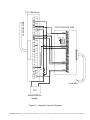
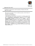
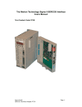
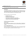
Application Note # 5437
Connecting Yaskawa Sigma-II Series Digital Amplifier
Introduction
This application note describes the procedure for properly connecting and tuning a
Yaskawa SDGH-01BE Sigma II series digital amplifier using a DMC-1700 controller
and an ICM-1900 interconnect module. While this document is specific to the DMC1700, it can be used as a reference for any OPTIMA series controller.
Components referred to in this document include:
•
•
•
•
•
•
Galil DMC-1700 controller
Galil ICM-1900 interconnect module
Galil WSDK servo tuning software
Yaskawa Sigma-II series Drive, Model SGDH-01BE
Yaskawa Interconnect Module CN-1, Model JUSP-TA50P
Yaskawa AC Servo Motor, Model SGMAH-01BAF41
Amplifier Hardware Connections
Hardware Setup
Set up Yaskawa Sigma-II digital drive and motor power supply per manufacturer’s
instructions. Connect the DMC-1700 controller to the ICM-1900 with the CABLE-1001m cable.
Connect Amplifier Enable Circuit
Ensure the ICM-1900 is Low Amp Enable (LAEN). Remove the resistor pack located
at RP1 on the ICM-1900. This turns the enable circuit into an open collector. Wire a
24-volt power supply into the enable circuit as shown in Figure (1).
1
Galil Motion Control, Inc. • 3750 Atherton Road • Rocklin, CA 95765 USA • 800-377-6329 • Ph: 916-626-0101 • Fax: 916-626-0102 • www.galilmc.com
To SDGH-01BE
CN-1 Breakout
ICM 1900/ICM 2900
GND
Remove Rpack
7406
RP1 U6
MOCMD
AMPEN
+MAX
+MBX
10K
GND
To
Controller
-
+
24V
External Power
Supply
Figure (1) – General Connection Diagram
2
Galil Motion Control, Inc. • 3750 Atherton Road • Rocklin, CA 95765 USA • 800-377-6329 • Ph: 916-626-0101 • Fax: 916-626-0102 • www.galilmc.com
Connect Encoder and Fwd/Rev inhibit Signals
The encoder signals are connected to the ICM-1900 from the CN-1 Breakout module.
It might be necessary to reverse polarity on one channel of the encoder wires (ie:
MAX+ connects to PA0-, and MAX- connects to PA0+) or swap the motor type in the
Galil software (MT-1) in order to avoid a runaway condition. The Yaskawa drive has
the ability to check for limit switches, but it is best to send those signals to the Galil
controller. Therefore, short the Fwd and Rev inhibit signal inputs to ground. Figure
(1) describes the proper connections for an x-axis system.
Connect Analog Motor Command Signal
Connect the MOCMD(x) ±10v analog motor command signal to the (TREF) pin on the
CN-1 connector. Refer to the Yaskawa User’s manual for details on all the
connections.
Software Settings and Operational Modes
The Yaskawa drive can be set up in numerous modes. Since the DMC-1700
generally outputs a ± 10-volt command signal, the Yaskawa drive is best suited for
analog torque or analog velocity mode. Choose this mode by working through the
operator interface on the drive as per Yaskawa manual’s instructions. Remember to
cycle power for any changes to take effect. To tune the motor, the Windows Servo
Design Kit from Galil was used. The General Test and Manual Tuning in the WSDK
seemed to give the best results. Contact an application engineer at Galil for
assistance in tuning the Galil filters.
To tune the motor, the General Tuning test was used. Using the virtual oscilloscope
further optimized the settings, minimizing settling time and steady state motor flutter.
The following was a fairly typical set of values:
FA 5
FV 7
KD 8
KP 1.5
KI .12
These values were obtained on a motor with no load in a fairly noise-free environment.
The amplifier was powered by standard US 110v ac power. Results may vary
drastically due to changes in voltage, load, temperature, or internal amplifier gain
settings.
3
Galil Motion Control, Inc. • 3750 Atherton Road • Rocklin, CA 95765 USA • 800-377-6329 • Ph: 916-626-0101 • Fax: 916-626-0102 • www.galilmc.com