1
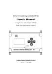
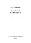
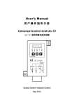
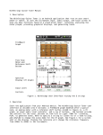
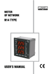
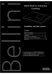
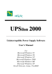
Universal monitoring controller UC-5u
User’s Manual
UC-5u 润滑系统控制器用户手册
Suzhou Leetern Industry Control
Ver 1.0
March 2010
Contents
1.Display and control panel
1.1 LED indicator lights
1.2 Keys
1.3 LCD display
2.Main lubricating function
2.1
Lubrication system states
2.2
Lubrication control channels
2.3
Lubrication control modes
2.4
Program on pulse
2.5
Monitoring and monitoring interlock
3.Parameter and function setting
3.1
Enter setting mode
3.2
Select manual mode lubrication
3.3
Set parameters
3.3.1
LUBRICATION parameter setting
3.3.2
PAUSE parameters setting
3.3.4
Pulse time setting
3.3.5
Pulse interval setting
3.4
Control parameter setting
3.4.1
Control mode setting
3.4.2
Monitoring interlock setting
3.5
Exit setting operation
4.Faults
4.1 Level monitoring and alarm
4.2
Compressed Air pressure monitoring and alarm
4.3
Signal monitoring and alarm
4.4
Fault message display and handle
5.Installation and electrical connection
5.1
Installation
5.2
Power supply
5.3
Electrical connection
6. Technical Specification
Universal Monitoring Controller UC-5 is designed for controlling and
monitoring of Lubrication systems. The controller UC-5 intuitively displays
operating information like operating state and parameters with LCD. It is easy
to use. UC-5 stores configuration data and parameters in EEPROM, which
made those data can be stored safely for long time.
UC-5 owns 2 lubrication control channels. Operating modes and control
parameters of each channel are completely independent, which make it can
separate control two lubrication systems at the same time.
UC-5 is of completely sealed design, Its protection grade reaches IP65, thus it
can work steadily in severe Industrial working environment.
Safety Warning!
There is AC high voltage on the PCB inside the controller. It directly
outputs high voltage power to drive lubrication pump. Mounting and using
UC-5 should be specially pay attention to safety, to avoid the danger of shock.
Mounting and connecting controller UC-5 must be done under power cut-off
condition. Hot-line work is prohibited to prevent electric shock hazard. Ground
terminal of UC-5 must be well grounded. The system should be protected with
specified fuse to ensure controller safe and personal security.
UC-5 must be mounted, tested and maintained only by trained qualified
personnel. In order to guarantee system operating safely and properly,
its safe condition should be periodically inspected.
UC-5 must be mounted, tested and maintained only by trained qualified
personnel. In order to guarantee system operating safely and properly,
its safe condition should be periodically inspected.
Although UC-5 complies with relevant safety technical requirements, the
use of the controller may still entail dangers leading to personal injury of
the user or third parties or damage to property. Therefore, the operation
must strictly comply with operation manual. Errors that may affect
safety must be rectified immediately.
UC-5 is designed for controlling and monitoring centralized lubrication
systems. The user himself shall be liable for any damage caused by
improper use.
1. Display and control panel
Display and control panel:
1.1 LED indicator lights
POWER – power indicator light. When power supply to the controller is
normal, the green indicator light of POWER is on.
INFO – Status information indicator light. When controller detects fault, the red
indicator light will be continuously flashing.
1.2
Keys
– Key UP. Scroll up key. When selecting menu, press key UP to scroll up
the menu; under setting mode, to increase the displayed value at cursor
position with this key.
– Key DOWN. Scroll down key. When selecting menu, press key down
to scroll down the menu; under setting mode, to decrease the displayed
value at cursor position with key DOWN.
– Key LEFT. Scroll left key. To move cursor left in setting mode.
– Key RIGHT: scroll right key. To move cursor right in setting mode.
–Key OK: To start MENU mode with key OK in display mode; Confirm
menu or programmed parameters; This key also has function to exit fault
state or advance terminate OIL DRAINING.
1.3
LCD display
LCD displays operating status and parameters.
When controller is operating, LCD mainly displays current states. Typical
display screen is as follow:
“状态: 润滑-自动”, system is now in LUBRICATION state, and the control
mode is automatic mode.
“设定: 05 分 00 秒”, preset LUBRICATION TIME is 5 minutes.
“剩余: 01 分 30 秒”, there is 1 minute and 30 seconds left for current
lubrication operation.
“监控: 状态正常”, all monitoring items of the lubrication system are in normal
states.
Controller may also display other contents, please refer to follow chapters for
detailed information.
Please note: Please use soft cloth with warm water or neutral detergent to
clean the film panel. Organic solvent is prohibited.
Do not use sharp tools/ object to touch the panel to avoid damage to the panel
and the sealed condition.
2. Main lubrication functions
Controller has multiple lubrication control functions. It can program
parameters relate to lubrication, monitor working states of the system, give
alarm and realizes interlock control.
Control owns power down protection function. When power is cut off, the
control unit auto stores operating status, remaining values and relative system
data at the point of power-off. When next electrify starts, the controller will
continue carrying out operation from last state when power off happened.
2.1
Lubrication system states
There are following states:
LUBRICATION – system is now in lubrication state, driving pump and
solenoid valve, lubricating those lubrication points. Lubrication state can be
initiated by controller under auto lubrication mode, or initiated by external
signal when controller is under external control mode. It also can be initiated
by manual operation.
PAUSE – system is now in PAUSE state.
STOP – system is now in STOP state. Typically after a failure, controller force
the system stop and enter in protection status.
Controller switch states according to preset operation mode and parameters.
2.2
Lubrication control channels
Controller owns two channels A and B. Channel B is always track lubrication
state. When controller goes to lubrication state, Channel B starts to work,
output drive current. When lubrication state finish, channel B closes, stop
outputting drive current.
Channel A also track lubrication state. But channel A is electric pulse output
type, it can output pulses according to programmed parameters, to drive
lubrication parts such as pump and solenoid valve. In order to meet different
lubrication systems’ application requirements, output pulse time and interval
time can be programmed.
Under special circumstances, pulse interval time can be set as 0 (zero). In
case of this, channel A will act as same as channel B, to continuously output
drive current in lubrication state and stop output drive current in
non-lubrication states.
2.3
Lubrication control modes
There are two control modes for user to choose from:
Auto lubrication
Under AUTO lubrication control mode, controller carries out task in continuous
cycle of “LUBRICATION-PAUSE-LUBRICATION…..”. At this time, lubrication
time and pause time can be separately programmed according to equipment’s
lubrication requirement.
In special case, PAUSE control parameter can be set as 0 (zero), then system
will work in lubrication state only.
Typical display screen of Auto lubrication mode are as follows:
In Auto lubrication control mode, lubrication system operating principle is
shown in the following figure.
Above figure also shows the way of working of channel A and channel B, and
channel A output pulse time, pulse interval time. For detailed information of
pulse time and interval time, please refer to later chapters.
External control mode
Under external control mode, controller follows up external control signals:外 if
external control signal works, controller goes into LUBE state; if external
signal are cancelled, controller quit LUBE state and go to PAUSE state.
Controller not only can accept 10-36V DC voltage signal’s control, relay dry
contact’s signal control, but also external proximity switch’s control.
Typical display figure under external control are as follow figures:
In the figure above, TIME means the time for this LUBE process. PULSE
means pulse quantity that lubrication channel A outputs for this LUBE process.
When controller returns to PAUSE state or STOP state, these two values are
cleared. And they are to be recounted again when next LUBE starts.
Working principle of the lubrication system under external control mode is
shown in the figure above.
Controller can select and set control modes between them.
Manual lubrication mode
In case to discharge the air in pipes or replace expired lubricant, “manual
lubrication” function is then required.
In “manual lubrication” state, controller ignores external control signals. It
carries out a lubrication cycle according to the preset LUBRICATION time.
When this lubrication cycle finishes, system automatically returns auto
lubrication control mode.
Manual lubrication can be initiated under all control modes and all operation
states. It is not limited by lubrication control modes and states.
Please note: If system is in failure state, please carefully using this
function. To avoid possible damage to lubrication system, do not use manual
lubrication function when the system is in failure state unless using this
function for testing or debugging.
In manual lubrication mode, LCD screen displays:
In manual lubrication cycle, press key OK on the panel can advance stop
lubrication period.
2.4
Pulse’s programm
Via program parameter for channel A, user can control output pulse
continuous time and interval time to meet different lubrication system’s
requirement.
Pulse time – pulse continuous time
Lubrication pump or solenoid valve are driven by electric pulses. Different
pumps and valves, different models or even different lubrication systems,
pulse time may be different.
Pulse time can be programmed. Programmable range is 0.05 s - 0.99 s.
Pulse interval time
In order to control the pulses density, interval time between two adjacent
pulses can be programmed. If the interval time is set as 0 (zero), then pulse
burst will change to a continuous and stable current.
Pulse interval time can be programmed in the range of 0-1.99 s.
2.5
Operation state monitoring function and monitoring interlock
Controller can monitor lubrication’s operation states according to user’s
requirements. When controller detects abnormal condition, it gives warning
message. If monitoring interlock function is set, controller will force the
lubrication system to get into stop state and stop lubrication tasks while it
gives warning signals.
3. Parameters and function setting
All functions and control parameters of UC-5 can be modified via setting
mode.
3.1
Enter setting mode
Press and hold key OK on the panel, after 3 seconds, controller gets into
setting mode. At this moment, screen shows the following figure:
Press key DOWN and UP to select the item and channel to be programmed.
Press key OK to confirm the item selected, and then goes to next step.
If there is no key board operation for more than 2 minutes, controller will exit
setting mode and returns display mode.
3.2
Manual Lubrication
If the item MANUAL LUBE is selected, press key OK, controller will then quit
setting mode. Controller gets into lubrication state and continuously shows
remain lube value until the manual lube finish or advance terminated.
3.3
Parameters setting
Select PARAMETER SETTING item, press key OK to get into parameter
setting state. Screen now shows:
Press key DOWN and UP to select the item to be programmed.
3.3.1
LUBE parameters setting
Select“AB: 润滑参数设定”, press key OK., then the parameter value under
this item will flash to remind user to change the value.
“AB:”means this parameter is set for both channel A and B.
Press key DOWN and UP can change the figure at cursor position. With key
LEFT and RIGHT can move cursor position.
LUBE parameter programmable range is 1s – 99min 59s.
Press key OK to confirm the new parameter and go to PAUSE parameter
setting.
Please note: Controller checks parameters in real time. If the newly set
parameters are beyond the programmable range, controller will refuse
the change.
3.3.2
PAUSE parameters setting
Press key ‘DOWN’ and select “AB: PAUSE”, then press key OK, the preset
PAUSE value starts flashing, user and modify the figure.
Select “AB: LUBRICATION” and press key OK, then preset lubrication time
can be modified.
PAUSE time programmable range is 0-9999 h 59 min 59 s.
Press key OK to confirm the newly set parameters.
3.3.3
Pulse time setting
Press key DOWN till the follow screen shows up.
Select “A: PULSE TIME SETTING” and press key OK, then user can modify
pulse time value. Pulse time value setting range is 0.05 s - 0.99 s.
“A:” means this parameter setting is only for channel A. Due to channel B’s
inherent characteristics, there are no pulse time and interval time settings for
channel B.
Press key OK to confirm new pulse time setting.
3.3.4
Pulse interval setting
Select“A: 脉冲间隔设定”, press key OK to change pulse interval value.
Setting range is 0-1.99s.
Press key OK to confirm the new pulse interval value.
Please note: We strongly recommend user not to set PULSE TIME and
PULSE INTERVAL as too small parameters. This because too small
parameters may result in lubrication system’s abnormal operation due to the
response speed of the solenoid valve cannot keep up.
User may keep pressing key DOWN or UP to return the main screen of the
setting mode.
3.4
Control setting
Select item to be programmed. For example, here we select ‘control setting”.
Press key OK, then screen displays:
3.4.1
Control mode setting
Select “控制方式设定”,press key OK. Then the preset control mode will flash.
Control mode can be changed now.
Use key DOWN and UP to change the control mode. Control mode can be
switched between AUTO CONTROL and EXTERNAL CONTROL.
Press key OK to confirm the new control mode.
If it is set as AUTO CONTROL mode, controller goes to LUBE state
automatically.
3.4.2
Monitoring interlock setting
Select INTERLOCK SETTING, press key OK, then the preset parameter start
to flash.
Use key DOWN and UP to change the setting. Interlock setting can be
‘INTERLOCK ON’ and ‘interlock OFF’.
After the monitoring interlock setting is set as ‘ON’, controller gives warning
signal and force the lubrication system stop once it detects any errors. If
monitoring interlock is set as ‘OFF’, then controller only gives warning signals
once error occurs.
Press key OK to confirm the new monitoring interlock setting.
During the setting period, once user change the monitoring interlock setting
mode from ON to OFF, if the lubrication is right in the stop state due to system
failure, then the system will return normal lubrication process and quit stop
state.
To terminate the control setting, user may keep press key DOWN or UP to
return to the main screen of the setting mode.
3.5
Exit operation
In the main screen of the setting mode, select EXIT OPERATION, press key
OK to terminate setting. Controller will then return display mode.
If there is any change in the setting, controller will automatically reboot after
user exit setting mode.
4. Faults and handle
Controller owns the ability to detect faults in lubrication system and give
warning information to keep the system working safe and reliable.
The monitoring function only performs when lubrication system is in operation.
Once controller detects error and gives warning signal, the error message will
be saved permanently until the message is manually cancelled.
4.1
Oil level monitoring and warning
The controller can detect the oil (lubricant) level via oil level switch. Oil level
switch will open when oil level is too low. When controller detects the cut-off
signal, it gives warning signal immediately. If monitoring interlock function is
set is ON, then the whole lubrication system will get into stopped state.
Oil level monitoring is always effective and cannot be closed via setting.
4.2
Compressed Air (CA) pressure monitoring and warning
Some lubrication systems use compressed air as motive power for the pump.
Controller can detect the pressure of compressed air to assure the system
working safe and reliable.
The pressure switch that mounted on the compressed air pipes will open
when pressure is too low. When controller detects the cut-off signal, it gives
warning signals immediately. If monitoring interlock function is set is ON,
then the whole lubrication system will get into stopped state.
Compressed Air (CA) pressure monitoring is always effective and cannot be
closed via setting.
4.3
Fault display and handle
When controller detects fault, LCD screen will show relevant fault information.
Meanwhile, the indicator light of FAULT on the panel is flashing. The contact
of fault output relay inside the controller will cut off to pass the fault
information to control room or other control system.
The fault information that caught by controller will be stored in EEPROM. It
will not disappear (even power-off) until user clears the message manually.
After handling the fault, press key “OK” shortly to quit Fault State and clear
fault information. Controller will then go back to normal lubrication cycle. But if
the reason that causes the fault still exists, the above operation does not
work.
If monitoring interlock function is set as OFF, the typical fault message to be
shown on the screen will be as follow:
If monitoring interlock function is set as ON, the typical fault message to be
shown on the screen will be as follow:
5.
Installation and electrical connection
5.1 Installation
Installation dimensions of the controller is show as figure above.
The control panel of the controller should be perpendicular to the earth, and
controller to be fixed on a place that is secure, non-violent vibration, no
corrosive atmosphere and out of direct sunlight. It is recommend fixing the
controller with machine screws. (Self-tapping screws should not be used to
prevent fall off damage to the controller with time passing.)
5.2
Power supply
Required power supply is: Voltage: 85~264V, 45~445Hz of industry frequency
AC. please input power class II.
For the controller is designed with multiple level power supply filtering, It can
effectively filter those strong interference that superimposed in power supply,
which ensures control system work well. Even so, it is still necessary to supply
the controller a separate power supply and avoid being power supplied
together with large-scale electrical equipment (such as frequency transformer)
that creates electrical interference easily. If the interference of the power
supply is too strong that the controller cannot work steady, user may connect
another filter to the power input side of the controller.
5.3
Electrical connection
Carefully pry off the small covers at four corners with small slotted screwdriver,
remove four screws inside. Lift top case and disconnect the flat cable that
connecting the Operate & control unit with Power and Input Output unit.
Put the top case aside carefully, the inside Power and InputOutput unit is
shown as figure below.
Connect external electrical equipment onto this Power and InputOutput board.
Electrical input and output terminals are indicated in the figure. From left to
right, the terminal code is 1,next is “2”, “3”etc. The definition of each terminal
is as follow.
Power input terminal J4
Terminal
code
Definition
1
AC_N
2
Not available
3
AC _L
4
Not available
5
PG
Instruction
AC_N
AC _L
Ground protection and interference clearance
J1: Output terminal of channel A
Terminal
code
Definition
Instruction
1
PG
Ground protection and interference clearance
2
Pump drive output N
To connect pump N
3
Pump drive output L
To connect pump L
J2: Output terminal of channel B
Terminal
code
Definition
Instruction
1
PG
Ground protection and interference clearance
2
Pump drive output N
To connect pump N
3
Pump drive output L
To connect pump L
J3: Fault signal output terminal
Terminal
code
Definition
1
PG
2
Relay contact A
3
Relay contact B
Instruction
Ground protection and interference clearance
JP1: External control signal input terminal
Terminal
code
1
DC 0V
Current circuit for DC 0V
2
External signal input
Connect external control signal
3
DC 24V
Supply work power of +24V to sensor
Definition
Instruction
JP2: Compressed air pressure switch input terminal
Terminal
code
1
DC 0V
2
signal input of Pressure switch
3
DC 24V
Definition
Instruction
Current circuit for DC 0V
Supply work power of +24V to switch
JP3: Level Switch input terminal
Terminal
code
1
DC 0V
2
signal input of level switch
3
DC 24V
Definition
Instruction
Current circuit for DC 0V
Supply work power of +24V to switch
JP4: Spare external input terminal
Terminal
code
1
Definition
Instruction
Current circuit for DC 0V
2
DC 0V
Spare signal input
3
DC 24V
24V power output
* Standby function, Please short circuit terminal 2 and 3 of the connector.
JP5: Spare external input terminal
Terminal
code
1
2
Definition
DC 0V
Spare signal input
Instruction
Current circuit for DC 0V
3
24V power output
DC 24V
* If user don’t use external control function, please short circuit terminal 2 and
3 of the connector.
The typical connection method between input terminal’s internal circuit
structure and external circuit is shown as figure:
Please note:
① The 24V power supplied by terminal is only for sensor and external
switch’s initiation. It is NOT allowed to use for other purposes due to its limited
load capacity. Otherwise, it may cause error to the controller.
② To meet controller’s needs, proximity switch must be 3-wires PNP
proximity switch with no load current less than 20mA.
When delivery, there is no openings on the controller’s shell (case). User
should make openings and connect wires depend on his own needs. Wires
should be brought out from PG waterproof joint to keep the tightness of the
controller.
In order to protect the Power and InputOutput unit from damage, please
remove it before making holes.
6. Technical Specification
Working voltage ----------------
85V~264V, 45~440Hz
Channel Max. power output---
>500W
Channel A pulse time ----------
0.05s~0.99s
Channel A pulse interval ------
0~1.99 s
Lubrication time ----------------
1 s~99 min 59 s
Pause time ----------------------
0~9999 h 59 min
External input signal -----------
10V ~36V DC,input equivalent resistant 5.1k
Fault relay output---------------
250V AC,5A Max,N.C.
Working temperature-----------
-25℃~+55℃
Fuse specification --------------
250V 0.5A
Protection grade ----------------
IP65
Without our written permission, any forms of translation, excerpt, copy,
print and reproduce of this USER MANUAL and its content is prohibited.
We reserve all rights to this USER MANUAL. We reserve the right to
revise it without prior notice.
Manufacturer: Suzhou Leetern Industry Control
Office: Rm. 501, Bldg. 45, No. 188, West Guoxin Road,
Wuzhong Dist. Suzhou, China
Technical Support Fax: +86-512-68661838
Technical Support Email: [email protected]
[email protected]
Website: http://www.leetern.com