1
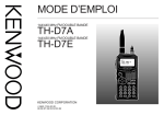
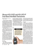
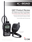
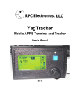
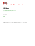
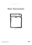
PRODUCT REVIEW Kenwood TH-D72A Dual Band Handheld Transceiver Reviewed by Howard Robins, W1HSR ARRL Contributing Editor [email protected] My adult working life began in 1969 in a digital integrated circuit development lab at Bell Telephone Laboratories in Allentown, Pennsylvania. So I have more than a casual interest in how the technology has evolved. I suppose I should not be so impressed with this handheld when I think about all the things my smart phone can do. I am impressed though. Kenwood has essentially put TM-D710A mobile radio functionality plus a GPS receiver system into a rugged, weather resistant package that runs for a long time on a rechargeable Li-ion battery, fits in your hand and can be worn on your belt.1 It’s a big step forward from the older TH-D7A that I used previously.2 In addition to being a great sounding, true dual band radio (can operate on two bands at a time) with wideband receive capability, the TH-D72A includes an internal GPS receiver, Automated Packet Reporting System (APRS) and a fully functional 1200 and 9600 baud packet radio terminal node controller (TNC). 3 Digipeater, EchoLink, Sky Command II and weather alert are also included capabilities. The ’D72A includes a feature called Advanced Intercept Point (AIP), which helps eliminate 1H. Robins, W1HSR, “Kenwood TM-D710A Dual Band Mobile Transceiver,” Product Review, QST, Feb 2008, pp 45-48. Past QST reviews are available to ARRL members at www.arrl.org/ product-review. 2H. Robins, W1HSR, “Kenwood TH-D7A(G) Dual Band Handheld Transceiver,” Product Review, QST, Apr 2008, pp 45-47 and S. Horzepa, WA1LOU, “The Kenwood TH-D7A Dual-band H-T,” QST, Aug 1999, pp 58-62. 3APRS is a software program and registered trademark of Bob Bruninga, WB4APR. July 2011 0.14 interference and audio distortion caused by intermodulation from nearby signals. The TH-D72A has all the features normally found in a modern dual band handheld, and they work well and are easy to use. Most hams will buy this radio for the unique APRS and packet features, and I’ll concentrate on those areas in this review. Description MCP-4A desktop software, USB drivers and firmware updates are available for free download from the Kenwood website. The software interfaces with the ’D72A via its USB port. Such software is almost a neces- Product Review Editor 0.1 Receiver Sensitivity (12dB SINAD, µV) 81@10 MHz I3 70@10 MHz Rx 60 90 Receiver 3rd-Order Dynamic Range (dB) 74@20 kHz* 69@20 kHz 70 Rx 40 Receiver 3rd-Order Dynamic Range (dB) 77 ChRej 50 69 90 Adjacent Channel Rejection (dB) 122* IF 60 IF Rejection (dB) 133* 110 134* Img 60 Snd 100 133* Image Rejection (dB) 440 Audio Output (mW) 110 800 136 T-R 250 PR061 136 50 Tx-Rx Turnaround Time (ms) 2 M 70 cm Key: * Off Scale Values shown are for band A receiver Bottom Line MCP-4A Desktop Software 0.16 SINAD 0.25 I3 The TH-D72A top panel has a male SMA ANTENNA connector, GPS receiver antenna, concentric twist controls for VOLUME and for channel/frequency/option control. On the left side are buttons for PTT, LAMP and MONITOR/SQUELCH. The right side has the following ports that are covered with rubber flaps: earphone (2.5 mm), microphone (3.5 mm), mini-USB, APRS COM (2.5 mm) and 13.8 V dc input. On the face are a POWER switch and an 18 button keypad. The four position jog control is used to index through and select menu options (Figure 1). The high resolution LCD is quite good. Even the smaller font used in some displays is easily readable. Included in the box are the antenna, wall charger, USB interface cable (A – Mini B type), PB-45L 1800 mAh Li-ion battery, belt hook, instruction manual and a CD with detailed information on all the features and options. Mark J. Wilson, K1RO 46 Key Measurements Summary Kenwood’s TH-D72A seamlessly folds APRS operation and a packet TNC into a full featured, easy to use dual band handheld. [email protected] sity to manage any radio with 1000 memory channel capacity and so many features and options. It is good to be able to back up all settings and channel information. MCP-4A will import repeater list files from ARRL Travel Plus for Repeaters. I tested this with an older version and it worked flawlessly. MCP-4A software also communicates with the GPS via the USB port. There will be more about GPS later. If you perform a firmware update, do not forget to back up all of your settings before you start. The last step in the update process is to do a total system reset. Table 1 Kenwood TH-D72A, serial number B0B00353 Menu System Receiver FM sensitivity: 12 dB SINAD, < 0.18 µV (Band A), < 0.22 µV (Band B). Receiver Dynamic Testing For 12 dB SINAD, Band A, 146 MHz, 0.14 µV; 440 MHz, 0.16 µV; Band B, 146 MHz, 0.15 µV; 440 MHz, 0.15 µV. FM two-tone, third-order IMD dynamic range: Not specified. 20 kHz offset: Band A, 146 MHz, 74 dB, 440 MHz, 69 dB; 10 MHz offset: 146 MHz, 81 dB, 440 MHz, 70 dB; Band B, 146 MHz, 73 dB*, 440 MHz, 69 dB*, 10 MHz offset: 146 MHz, 79 dB, 440 MHz 70 dB. FM two-tone, second-order IMD dynamic range: Not specified. Band A, 146 MHz, 89 dB, 440 MHz, 99 dB, Band B, 146 MHz, 89 dB, 440 MHz, 98 dB. Adjacent-channel rejection: Not specified. 20 kHz offset: Band A, 146 MHz, 77 dB, 440 MHz, 69 dB; Band B, 146 MHz, 73 dB, 440 MHz, 68 dB. Spurious response: Not specified. IF rejection, Band A, 146 MHz, 122 dB, 440 MHz, >133 dB; Band B, 146 and 440 MHz, 121 dB. Image rejection, Band A, 146 MHz, >134 dB, 440 MHz, >133 dB; Band B, >133 dB. Squelch sensitivity: < 0.13 µV. At threshold, Band A, 146 MHz, 0.14 (1.4 µV max), 440 MHz, 0.15 (1.6 µV max); Band B, 146 MHz, 0.13 (1.4 µV max), 440 MHz, 0.13 (1.4 µV max). Audio output: 0.3 W. 0.44 W at 10% THD into 8 : (external speaker). THD at 1 V RMS, 1.9%. Transmitter Power output: VHF, 5 W (high), 0.5 W (low), 0.05 W (economy low). Transmitter Dynamic Testing 146 MHz, 5.3 W (high), 0.6 W (low), 0.1 W (eco low); 440 MHz, 5.3 W (high), 0.5 W (low), 0.1 W (eco low) at 8.4 V dc (full charge). Spurious signal and harmonic suppression: >60 dB (highest transmit power). 146 MHz, >70 dB, 440 MHz, >70 dB, meets FCC requirements. Transmit-receive turnaround time (PTT release to 50% of full audio output): Not specified. Squelch on, S9 signal, 136 ms. Receive-transmit turnaround time (“tx delay”): Not specified. 70 ms. Very much like the TM-D710A, the THD72A has a tiered menu system to adjust settings. All user settings can be entered or modified by MCP-4A software via the USB port or by keying in on the transceiver itself. There are four major areas available for programming: 1XX – Radio, 2XX – GPS, 3XX – APRS and 5XX – Sky Command. (Note that there is no 4XX range addressed in the user documentation.) Pressing the MENU key on the radio brings up the main menu display with these four selection items. You can scroll through these with the jog control or one of the twist knobs. Pressing the jog control down or up indexes through the options; pressing to the right selects the options. The menu items/options are not necessarily in alphanumeric order, but rather in some logical order for their use. This tiered system, along with the jog control, makes managing so many settings on a handheld very easy. APRS Much of the functionality in the TH-D72A is the same as the TM-D710A, so I will focus here on what is different and particular to the handheld. Pressing the TNC (2) button on the keypad toggles through APRS12, PACKET12 and NO TNC. With APRS12, the internal GPS locked on position, and BCON displayed (BEACON button pressed to turn on beaconing), the radio transmits that position. Station ID icons are supported for 57 stations, versus about 30 on the ’D710A (others have been added in subsequent firmware updates). Station List There is capacity to store information for 100 received stations. New data replaces old for the same stations on the Station List and the 101st station will replace the oldest on the list. Repeatedly pressing the LIST key cycles through different display options. The first press displays the last three stations received — call sign and secondary station identifier (SSID). The next press displays the last five received stations, SSIDs and their equipment (for example, W1HSR-6 TH-D72) using a reduced font size. The third press of Manufacturer’s Specifications Measured in ARRL Lab Frequency coverage: Receive, Band A, 136-174 MHz, 410-470 MHz; Band B, 118-174 and 320-524 MHz; transmit, 144-148 MHz, 430-450 MHz. As specified. Modes: FM, Data FM, FM narrow, data. Power requirements: With PB-45L battery pack, Receive, battery power, 325 mA (max receive with no signal, 100 mA (single band), volume, no signal, lights on, dual band), 150 mA (dual band), 135 mA (TNC on, no 150 mA (standby, lights on dual band), signal), 30 mA (battery saver on); transmit, 2.0 A 30 mA (power save), 133 mA (TNC on, (high), 0.8 A (low), 0.5 A (eco low) at 7.4 V dc no signal); transmit, 2.0 A (high), 0.7 (nominal voltage); with external 13.8 V dc, A (low) 0.4 A (eco low) at 8.4 V dc (full 1.6 A (transmit, high power).† charge). 1.4 A (high power) at 13.8 V dc. Size (height, width, depth): 5.5 × 2.3 × 1.6 inches, including projections. Weight, 13.1 ounces. Price: $500. †PB-45L 7.4 V, 1800 mAh Li-ion battery supplied. Replacement battery, $90; PG-3J cigarette lighter adapter, $40; PG-2W dc power cable, $20; KSC-32 rapid charger, $65; BT-15 battery case (6 AAA cells), $35. *Measurement was noise limited at the value indicated. the LIST key displays the last five received stations’ call sign, SSID, time heard and QSY frequency indicator (eg W1HSR-6 16:04F — the F indicates that there is a QSY frequency in the Status text field; more on this later). You can use the jog control to navigate the station list. There are nine pages of information for each station that can be viewed with the push of the jog to the right. You can back up by pushing the jog to the left. Pushing the July 2011 47 received at another ’D72A or ’D710A, it is indicated on the Station List (Figure 2). On the TH-D72A, while viewing the Station List, pressing MENU and selecting TUNE will tune the non-data band to the QSY frequency, tone and shift (if provided) of the selected station. I tested to see what the ’D710A would do with the additional information received from the ’D72A. My ’D710A did, in fact, tune to the received QSY frequency and the associated tone and shift set automatically. Beaconing Method Options Figure 1 — The jog control at the upper left of the keypad is used to navigate through the menus. jog up or down will display the same page for stations above and below on the list, respectively. The list is easily and quickly sorted by call sign, date/time or distance. Filtering by station type — weather, mobile, digipeater and so on — is also a quick menu selection. Voice Alert Common practice among many APRS users is to set up their radios to send a 100 Hz tone with beacons and set CTCSS to the same tone. This squelches the receiver normally and only opens it to allow packet clatter to be heard when stations are within simplex range of one another. This is a settable menu option called Voice Alert on the ’D72A. The idea is if you are close enough for the tone to open squelch, you are close enough for simplex voice communication. This could be used in conjunction with the QSY function described next. QSY Function The TH-D72A has an implementation of Automatic Frequency Reporting System (AFRS) that embeds your non-data band frequency and other parameters (tone frequency, shift and more) into a Status Text (see www.aprs.org/freq/AFRSspec.txt). When this QSY frequency information is Manual, PTT, TX Interval Time, Decay Algorithm, Proportional Pathing and SmartBeaconing are supported.4 SmartBeaconing causes positions to be beaconed based upon speed of movement and turn angle. You can set the low and high speed thresholds and beacon rates for each. For example, you can set beaconing to occur every 30 minutes for speeds below 5 MPH, and in a nonlinear fashion increase beacon rate to every 60 seconds for speeds between 5 and 60 MPH and above. In addition, you can set position beaconing to occur when a combination of settable turn angles and speeds are measured on the GPS receiver. There is a page dedicated to Smart Beaconing in the APRS menu of the MCP-4A software that graphically displays the effects of your settings. When SmartBeaconing is turned on, the TX Interval Time, Decay Algorithm and Proportional Pathing features will not operate. Quick Beacon is another option. When METHOD is set to any value other than Manual, you can manually transmit a beacon by pressing F, BCON (6). Message Handling The TH-D72A has eight user programmable preset phrases, versus four on the ’D710A. In addition you can set up an au4Beaconing options are described very well with tables in Kenwood TH-D72_10_ APRS_E.pdf, which is part of the Owner’s Manual on CD and available for free download from www.kenwoodusa.com/Support/ Amateur_Radio. SmartBeaconing is from HamHUD Nichetronix, www.hamhud.net. Figure 2 — Station list with QSY frequency information (see text). 48 July 2011 tomatic reply message. These phrases and messages can be created using the MCP-4A software, or on the handheld itself via the keypad and menus. I tested sending and receiving messages with my portable packet station and it worked flawlessly at both ends. I sent a message to the ’D72A and it sent back the automatic reply message that I had set up. Then I replied to the message using preset phrases, and they were received. I also created a new message using the keypad and the twist control on top. That was pretty easy to do. Using the twist control, as you move one character position to the next, the last character used is in the buffer, so you are not always starting at the beginning of the character set. I find this efficient. Message and Bulletin Group filtering is supported, so you can set it up so only group members can exchange messages. APRS Serial Port Interface I tested the TH-D72A with my AvMap G5 GPS receiver using the APRS serial port and an interface cable that I use with my TM-D710A. There are port settings that can be made using the keypad in menu mode or via the MCP-4A software and the USB port and cable. I set the baud rate to 9600, input to GPS and output to waypoint. Waypoint can be set to NMEA, Magellan or Kenwood. I used Kenwood and nine character length. Once all these settings were loaded, simply pushing F (function) and MARK/GPS (1) toggled between the internal and external GPS. In external GPS mode the icon on the LCD changes from iGPS to GPS. After satellites were located and my position was known, the GPS icon changed from static to flashing — the G5 and ’D72A were talking to each other and the ’D72A transmitted a position beacon. The communication is bidirectional as received positions appeared on the G5 screen and accumulated in its APRS Contacts list. This interface can also be used with Davis and Peet Brothers weather stations via menu selection. A wiring diagram is provided in the documentation to support these connections. GPS Receiver System I am an avid power walker and wear a Garmin GPS watch to capture my treks and record my stats for later review. I am able to export a file that can be imported into Google Earth. Once I have done that, I can share my treks with my friends. So, one of the first things I wanted to learn was if I could use the TH-D72A’s internal GPS receiver in similar fashion. The answer is yes! In addition to providing position information to the internal APRS, there is full flexibility as to what you can do with the GPS receiver data. Before I left for my walk, I went into the on both packet terminals. This worked well. I was also able to connect to the PBBS in the KPC-3 TNC and leave a test message. I have a bit of experience with interfacing radios and TNCs with computers. This was by far the easiest to make work. There are no mic and speaker connections or audio levels to adjust, no special interface cables — just a standard USB interface cable and readily available PC terminal software. Battery Power Conservation Figure 3 — The TH-D72A recorded my walk for display on Google Earth. GPS menu and set LOG SETUP to use time as the RECORD METHOD and INTERVAL to every 10 seconds. You can use DISTANCE with intervals from 0.01 to 9.99 miles. You can, alternatively, use BEACON as your log record method (a waypoint would be recorded each time an APRS beacon is transmitted). A little quirk mentioned in the documentation is that the GPS logger cannot be turned on while the APRS COM port input is ON. This became an issue as I tested the ’D72A with the AvMap G5 before I tested logging. I had to turn OFF the APRS COM port input. Simply pressing F, 2 starts and stops the log. The iLOG icon appears in the GPS position on the LCD when the log is on. Up to 5000 track points can be recorded. The MCP-4A desktop software uses the USB port to read GPS logger data from the ’D72A. Once the data is read, it can be stored in various standard formats that can be imported. In my case, I saved the data as a .gpx file that instantly imported into Google Earth. I was able to share this file with friends so they could also view my trek on Google Earth. Clicking on that file brings up my trek on Google Earth (Figure 3). You have the option of clearing the track log or letting it accumulate. You can manually enter or save marked waypoints as target points. Up to five such points can be saved and used as a navigation tool. By this I mean that the radio with the GPS locked on your position can tell you distance and direction to the target. The TH-D72A’s real time clock is set by the GPS, and there is a menu item to set your local time zone. Packet TNC I put the TH-D72A into PACKET12 mode by pressing the TNC (2) button on the keypad. PC access to the internal TNC is via the USB port, so I used HyperTerminal on my PC running Windows XP Home Edition. The Packet PDF file that comes as part of the instruction manual CD does not tell you how to physically connect to the TNC via USB or serial port. Also, that PDF document includes a list of the commands that the TNC is supposed to respond to. I tried to set up the internal mailbox, but none of the mailbox commands worked. I sent e-mails to Kenwood Support concerning these issues and received responses from them within a few hours. Unfortunately, they told me that the command list was copied from the TMD710A user manual, and that the TH-D72A does not have a packet mailbox. I was able to connect to the internal TNC and found a fairly robust AX.25 command set. I tested the switch from 1200 to 9600 baud and observed that the icon on the LCD did change from PACKET12 to PACKET96 with the parameter change. I had no way to actually test 9600 baud packet with another node. I was unable to find an actively working packet node of any type where I was doing this review, but I was able to connect to my portable packet station, automatically go into CONVERSE mode and send and receive text There are several strategies available to extend the life of a charge. Radio options include automatic power off timer and battery saver mode, which will turn the receiver circuit off for a settable period from 0.03 to 5 seconds if squelch is closed and no key is pressed for more than 10 seconds. RF power output can be set to Economy Low (0.05 W), Low (0.5 W) and High (5.0 W) GPS options include GPS off, GPS-only mode and GPS battery saver mode. Battery saver turns the GPS off if position data is not determined during the maximum catching time (approximately 5 minutes). Also, when there are many satellites in range and the GPS is stabilized and position data can be determined, the GPS power source repeatedly turns on and off. Off time is user settable to 1, 2, 4 or 8 minutes, or Auto. When set to Auto, the GPS off time starts at 1 minute for the first time, then progresses to 2, 4 and 8 minutes each additional time. The GPS off time remains at 8 minutes thereafter. After having determined your position for the duration, however, if the GPS cannot pinpoint your location, the GPS off time will restart at 1 minute. APRS beacon rates, whether controlled by an algorithm or SmartBeaconing, will affect the life of a battery charge. I set the ’D72A to beacon a position every five minutes at high power and with the internal GPS receiver on all the time. I started with a fully charged battery and let it run until it shut itself off. It ran like that for 17 hours. It took six hours to fully recharge the battery with the supplied wall transformer. Thanks to AC4XQ and K4ABB for digipeating and igating my beacons for all that time. Bottom Line The TH-D72A is an impressive work of art. It might seem pricey, but when you consider all that you are getting — true dual band radio, GPS receiver system, 1200 and 9600 baud TNC, computer interface cable and great software — there’s really nothing else to buy. It is an amazing package. Manufacturer: Kenwood USA Corp, 3970 Johns Creek Ct, Suite 100, Suwanee, GA 30024; tel 310-639-4200, fax 310-7618290; www.kenwoodusa.com. July 2011 49 Down East Microwave L222-28 11⁄4 Meter Transverter Reviewed by H. Ward Silver, NØAX ARRL Contributing Editor [email protected] Table 2 Down East Microwave L222-28 11⁄4-Meter Transverter, serial number 1015 I’m a budding VHF+ contester with one of the now-ubiquitous HF/VHF/UHF transceivers (an IC-7000) that covers all amateur bands from 160 meters through 70 cm. Except, that is, for the 11⁄4 meter band of 222-225 MHz. ARRL VHF+ contests have a four band “Limited Rover” category (www.arrl.org/generalrules-for-arrl-contests-above-50-mhz) that dangles the tantalizing 11⁄4 meter carrot before the noses of Missouri mules like me who have the “easy three” — 6, 2 and 70 cm — but haven’t made the leap to a fourth band. So when the ARRL asked if I’d like to give the 25 W version of the Down East Microwave (DEM) L222-28 transverter a try, it was an easy “yes.” Not one to leave any cookies in the jar, I suggested adding a four-band antenna to the review, the Tennadyne T-28 described in the accompanying review. Done — with the January ARRL VHF Sweepstakes contest coming up, it was game on! Manufacturer’s Specifications Measured in the ARRL Lab Frequency coverage: Receive and transmit, 222-223.7 MHz. As specified. Power requirements: Transmit, 6 A maximum, 13.8 V dc; Receive, not specified. Transmit, 3.85 A (at 25 W output); receive, 520 mA at 13.8 V. Modes of operation: CW, SSB, AM, FM, PSK As specified. Receiver Conversion gain: 17 dB minimum. Receiver Testing 28 MHz, 18.6 dB; 29.7 MHz, 17.3 dB. Noise figure: <1.0 dB. 0.8 dB. Image rejection: Not specified. 103 dB. Third-Order Output Intercept: Not specified. +9 dBm. Transmitter Frequency accuracy: Not specified. Transmitter Testing 28.000 MHz in = 222.000004 MHz out (0.018 ppm error) Frequency drift: not specified. After one hour in standby, five cycles of 30 s key down, 30 s key up; 0.04 ppm or 9 Hz. After 10 minutes key down, 0.09 ppm or 20 Hz.* Transmit RF input: 10 mW maximum. Adjustable, see text. Transmit RF output: 25 W. As specified. L222-28 Transverter Overview Power output drift: not specified. After one hour in standby, five cycles of 30 s key down, 30 s key up; 0.4% or –100 mW. After 10 minutes key down, 1.2% or –300 mW.* Spurious and harmonic suppression: Not specified. 73 dB; meets FCC requirements. Intermodulation distortion (IMD): Not specified. 3rd/5th/7th/9th order, –23/–43/–54/–62 dB below PEP The L222-28’s standard version has a Bottom Line The Down East Microwave L222-28 transverter is a fine solution for amateurs looking to expand station coverage to the 11⁄4 meter band. It can be adapted to interface with a variety of radios and receives and transmits well. Size (HWD): 4.2 × 6.9 × 11 inches, including protrusions; weight, 4.6 lb. Price: $479. *These are new measurements described on the QST-in-Depth website at www.arrl.org/qst-in-depth. Figure 4 — The L222-28 transverter features a simple front panel and an oversized heat sink. The power meter is an LED bargraph style. 50 July 2011 Figure 5 — The rear panel of the L222-28 features an AUX connector with all control signals so that no additional connectors are required if the configuration is changed. 25 W output for an IF drive level of 10 mW (gain is adjustable internally) or an external low-power HF transceiver can also be used. On receive, better than 1.0 dB noise figure and 17 dB of conversion gain help you hear weak signals without the need for a preamp. The unit operates from 12 V dc and draws 6 A, maximum. The transverter’s enclosure is topped with an oversized heat sink and cooling fan (see Figure 4) — you can run this unit hard at full-power and it should be able to dissipate the heat easily. The transverter seemed to be rugged enough for rover use. The transverter is available as a kit as well as fully assembled (the model tested). ARRL Lab measurements can be found in Table 2. Interfacing and Using the L222-28 The L222-28 can be configured to split the receive and transmit inputs and outputs or combine them into a common signal path (standard). Keying requires the usual switchto-ground PTT signal (positive keying is also supported) and four-step sequencing is also provided. An option for RF sensing is provided and a negative voltage ALC output is available on the rear-panel AUX connector to control transceiver output power. Figure 5 shows the connections available. DEM includes a useful selection of connectors and adapters for both control and RF connections — I appreciate that gesture. As a rookie transverter user, I made pretty much every configuration mistake you could make. I could sense the L222-28 patiently waiting for me to get the interface configuration right, sighing deeply and drumming its fingers on the shelf. Involving both radio and transverter, this process was not trivial and while a setup process is given in the manual, it’s not all that easy to figure out. DEM offers a helpful page on transverter interfacing on their website. (See the section “Manual and Examples.”) The user’s manual is essentially drawing-free (block diagrams needed) and the technically dense text assumes a familiarity with VHF/UHF operation that I don’t yet have. Nevertheless, I persevered and then I got it — the combination of rig settings and IF connections got ’er done and at the next tap of the key paddle, the L222-28’s power meter LEDs blinked red and my wattmeter needle jumped up-scale. I was on 11⁄4 meters CW and SSB! Once you get the transverter and radio hooked up correctly, operation is automatic. You take care not to overdrive the transverter and it pretty much does the rest. The transverter’s model number, 222-28, describes the frequency conversion process: to operate on the 222.1 MHz calling frequency required that I set the radio to 28.1 MHz. The unit can withstand high SWR (although probably not indefinitely at full-power input) — also personally verified. SSB and CW reports were good — both strength and quality. (I had an odd monitor feedback problem at first but that turned out to be a radio configuration error.) Manual and Examples The manual for the transverter is okay — it has have enough information to get you from the cardboard box to putting out a signal but in a dense format that assumes a lot of the new user or builder. Equipment such as a transverter that is used in association with other gear can be very hard to install correctly — sometimes (luckily, not in my case) leading to accidental damage. I realize that the manual cannot contain an example of every possible radio interface but manufacturers should encourage their users to post descriptions of their successful configurations on the company website or in a free Yahoo or Google group. By definition, transverter customers need this information — make it easy for them to find it…without having to spend time searching the Internet. Summary If you are considering adding 222 MHz to your rover or base station, the L222-28 is a solid package, ruggedly built, that works well with modern HF transceivers. It has enough interface options to adapt to a variety of radios and is robust enough to deal with life in the ham shack. If I decide to get serious about VHF+ contesting, I’ll seriously consider buying one for 222 MHz. Manufacturer: Down East Microwave, 19519 78th Terrace, Live Oak, FL 32060, tel 386-364-5529; www.downeast microwave.com. Tennadyne T-28 VHF/UHF Log Periodic Antenna Reviewed by H. Ward Silver, NØAX ARRL Contributing Editor [email protected] The T-28 delivers useful performance over four-and-a-half octaves of frequency — from 50 MHz to 1300 MHz — on a single structure. (See Table 3 for specifications.) The log-periodic’s usual crisscross transmission line that drives the array of 28 elements is integrated into the supporting doubleboom — a pair of square tubes to which the elements are mounted. In fact, with its 12 foot boom and turning radius of 7.5 feet, the T-28 looks just like a super-sized version of a standard TV antenna and that’s what the neighbors will think it is when you put it up. Whether you enlighten them is up to you, of course. In fact, the T-28 can be used as a TV antenna if you used an appropriate diplexer or antenna switch. It might require a bit more rotator than the standard TV antenna (I’m using a Ham-IV) but a sturdy installation is in everyone’s interest, if you get my drift. I’m sure the armchair lawyers are already Table 3 Tennadyne T-28 Specifications Frequency coverage: Boom length: Half-power beamwidth: Front-to-back ratio: Weight: Wind load: Turning radius: Typical max SWR: Feed point impedance: Price: $415. 50-1300 MHz. 12 feet. 50 degrees. up to 45 dB. 17 pounds. 3 square feet. 7.5 feet. 1.75:1. 50 : wondering about antenna restrictions and TV reception and that sort of thing. This is not a high gain antenna — the specifications claim 6.3 dBd and that’s about right from what I observed on the air. The front-to-back ratio was observed to be anywhere from 3 to 5 S units (18 to 30 dB at 6 dB per S unit) during the contest. (Tip — do not try to do a product review and make a decent contest score at the same time!) All in all, it was a lot better than a dipole or whip and not as good as long-boom Yagis on taller towers. Assembling and Installing the T-28 Bottom Line The Tennadyne T-28 log periodic is ruggedly built and will get you on six amateur bands with some gain and a single feed line. Figure 6 shows the parts that you get when you open the box and sort them out — there are lots of pieces, including small ones. The smaller tubes are not bagged — count them before beginning and be sure you have retrieved all 56 element halves from the packing. Read through the instructions completely before beginning and practice with the elements, clamps and inserts to be sure of correct assembly. Make sure you understand July 2011 51 the process of alternating elements a Bird wattmeter to measure the between booms. (See the comments SWR on 6, 2, 11⁄4 meters and 70 cm below on Manuals and Examples.) with the following results averaged I recommend that you assemble across each band through 50 feet of the antenna either indoors (measure RG-213 coaxial cable: the exterior door first — do not ask Frequency Average me how I know to do this) or in the SWR garage or somewhere over a smooth 50-54 MHz 1.4:1 surface on which a 6-32 nut can be 144-148 MHz 1.8:1 seen after you drop it. (Tennadyne 222-225 MHz 1.7:1 kindly supplied some extra hardware 430-450 MHz 1.9:1 for the inevitable, “Oops!”) Because there are so many elements of not-so(I do not have equipment for 902 different lengths, I also recommend and 1296 MHz at the moment.) The that you pair them up and sort by specification is for a peak SWR of length so that you minimize the 1.75:1 and these figures are within chances of installing them out of the range of measurement error of order. (Don’t ask me how I know to meeting that spec. do this, either.) Once the antenna was installed Start with the small elements to sufficiently above the roof (and with learn the right technique of inserting additional clearance from the wire the element through the boom, then doublet) it played well and continthe screw through the element, and ues to play well. Figure 8 shows getting the Nylok nut started on the Figure 6 — The parts and pieces received from Tennadyne. the antenna against a high January screw. Both 3⁄8 and 5⁄16 inch nutdrivers Assemble the antenna over a smooth surface to prevent sky. I received good signal reports are required for this operation and losing any dropped pieces. and could work any station I heard. a punch awl is handy for lining up Swinging the beam back and forth element holes inside the boom. A portable you have a lightweight mast) you’ll want to confirmed the expected directivity. We’ve had workbench with a vise to hold the boom add some weight in the hollow booms at the several episodes of high wind or storms and while you work makes things easy. Once each rear. Metal rod or bar works well and can be I’ve noticed nothing amiss with the antenna. individual boom is assembled, double-check secured with a screw through the boom. I recently noticed an unexpected feature that you have the right element in the right while working in the backyard garden. What place before final assembly and attachment T-28 Performance was that faint calliope music and where of the feed line. Figure 7 shows the partially Up in the air with plenty of time before was it coming from? As it turns out, the completed antenna. the VHF Sweepstakes, I was able to give the open-ended elements were resonating in Mounting the antenna on the mast is antenna a spin. Initially, the SWR seemed the breeze with different notes sounding as straightforward and can be done by one per- a little high, particularly on 6 meters when the wind speed and direction varied! You son. The antenna weighs less than 20 pounds the antenna was aligned with the rearward get free wind-chimes with the antenna — if but it is unwieldy and with so many elements, elements parallel to a nearby wire doublet that might be a problem, a piece of sponge you have to hold it above your head while — hardly a surprise. In the final installation, or foam inserted into the end of each element attaching the boom-to-mast hardware. The I found it necessary to have the antenna will eliminate it. mounting point is not at the balance point — at least 3 feet above the composition roof and there is more weight towards the front of the clear of the doublet before SWR stabilized Manual and Examples As with the L222-28 transverter, the antenna — so if that is important (perhaps on the 2 meter through 70 cm bands. I used manual is okay but assumes a lot of the builder. In particular, for this complex antenna with many opportunities to get things wrong, why not supply a step-by-step checklist? A text paragraph with several steps may contain the necessary information but a checklist augments the graphics by 10 dB! Putting supplementary information online would cost nothing and avoids adding paper pages. Summary Figure 7 — Be sure to alternate the elements as described in the manual. 52 July 2011 Figure 8 — The T-28 at about 35 feet looks a lot like a TV antenna while doing an effective job on six amateur bands. The T-28 log periodic is a good singleantenna compromise to getting on the VHF and UHF bands without breaking the budget. It’s not a high-performance, tight-pattern band-burner but it gets you on six amateur bands with some gain and a single feed line. Giving the evaluation unit a permanent home on my roof was an easy decision! Manufacturer: Tennadyne, PO Box 352, Alto, MI 49302; 616-622-4968; www.tennadyne.com. SHORT TAKES Ten-Tec 1054 Shortwave Receiver Kit construction time took me about two hours, which included many “What are you doing Bob?” conversations in the ARRL Lab. The Purpose of the Ten-Tec 1054 kit is for the beginner to experience the joy of kit building. With that in mind, Ten-Tec has left the purchase of knobs, a case, and antenna connections to the builder. I found inexpensive knobs online at Jameco (www.jameco.com). A clip lead, cut in half, served as antenna and ground tie points. Before operating, I strongly suggest trying out the receiver for the first time with headphones off, until you get to know how the regeneration control works. Loud squeals can be generated while adjustments are being made. Once you learn the ropes you’ll become comfortable with how to tune the radio. Learning the quirks of the REGEN control is key. To listen to an AM station (such as a shortwave broadcaster), all you need to do is carefully tweak the REGEN knob until you find the point just before regeneration breaks into oscillation. Once a station is heard, the volume can be increased. When you’re listening to CW or SSB signals, you’ll want to turn the REGEN control until the circuit begins oscillating. Bob Allison, WB1GCM ARRL Test Engineer [email protected] What’s a low cost electronic kit that can be built in a couple of hours by a novice builder? That’s the question I pondered while planning this year’s kit building exhibition at the ARRL Expo at the Dayton Hamvention®. Novice builders of all ages have sat in our Expo work area to build small but useful Amateur Radio related kits for the past two years, enjoying the experience of following instructions, soldering and using hand tools while being mentored along the way. To accompany our new code practice oscillator kit, I needed another practical project. I was pleasantly surprised to learn that Ten-Tec offers receiver kits for sale. I picked the model 1054; a regenerative, four-band receiver, covering 5.9-6.4, 6.9-7.4, 8.5-10.2 and 11.5-16.5 MHz. The 1054 manual is geared to the beginner; it explains what shortwave radio is, what can be heard on each of the four bands, (logging page included), what regeneration is and how the circuitry works. The back cover of the manual has several useful charts; a resistor color code chart, inductor and capacitor chart for the parts used, Ohms Law and even a chart with the formula for a quarter wave antenna. Build It and Listen The completed kit is powered by two 9 V batteries; one for the receiver circuit, the other for the LM386 audio amplifier circuit. All controls are on the front panel. At left there are three push- buttons; one for power on/off and the other two for selecting the frequency range. Three controls dominate the rest of the panel; (varactor) tuning, regeneration and volume. The 1054 kit has been around for a while and, understandably, some parts are different from the initial design, so Ten-Tec includes an addendum sheet of part corrections and manual instructions. The instructions are The Ten-Tec 1054 receiver in its optional oak accessory cabinet. An inside look at the Ten-Tec 1054. Educational and Fun clear, starting with taking inventory of all parts and hardware. I always lay out parts neatly on an uncluttered work area. If you’ve never soldered before, have someone show you, or check out some of the “how to solder” videos on line (don’t forget your safety goggles). About one third of the way into construction, the audio amplifier circuit is completed and a simple test for audio hiss is performed. For listening, an inexpensive set of stereo headphones work best, though there are labeled points on the circuit board for a speaker. I noticed the 1⁄8 inch headphone jack is wired for a stereo plug. A mono (two conductor) plug could damage the audio circuit. Overall Steve Ford, WB8IMY QST Editor Please remember, while this is a Ten-Tec, it’s not a Ten-Tec Eagle transceiver. The 1054 is a simple regen receiver, which means it is sensitive, but not selective. Even so, I suspect even a veteran ham will get a fair amount of enjoyment from this kit. With a 30 foot piece of wire I listened to many amateur and shortwave stations. In fact, I was pleased enough to purchase the optional solid wood case with speaker. The Ten-Tec 1054 is a perfect “first kit” for a beginner, or a clever, entertaining diversion for the experienced amateur. Manufacturer: Ten-Tec, 1185 Dolly Parton Parkway, Sevierville, TN 37862; www.tentec.com; tel 800-833-7373. $39. Oak accessory cabinet: $39. [email protected] July 2011 57