1
Programming
tools for SAIA®PCD controllers
Programming, project planning and configuration of PLC-based systems
Advantages of the PG5 programming tools
Program portability: PG5 programs can run on all SAIA® PCD platforms.
User Manual
Program organization by files (containing several program blocks) simplifies
the shared use of program files between several SAIA®PCD controllers.
Accepts existing PG3 and PG4 programs.
Programming and debugging environments united in each program editor.
Simple programming of terminal displays with the HMI Editor.
Powerful instruction set supported by macros and assem bler directives.
Features of the PG5
Symbol Manager administers all local, global and network symbols or symbol
groups. Automatic address allocation largely dispenses with the need for
fixed addressing.
Project Manager administers complex installations of networked PCDs, including
displays and documentation.
Online functions for commissioning and error detection via Ethernet-TCP/IP,
SAIA®S-Bus, modem, etc.
Integrated programming environments:
– FUPLA (function block diagram)
– S-Edit (instruction list IL)
– GRAFTEC (sequential function chart)
Integrated network editors for SAIA®S-Bus, PROFIBUS DP and FMS, LONWORKS®.
Extensive additional libraries broaden the scope of PG5 functions.
Edition 26/732 E10
Saia-Burgess Controls Ltd.
PG5-WorkShop I General I 23.01.06
I
II
Saia-Burgess Controls Ltd.
Contents
Preface
1
PCD – Quick-start
2
3
4
5
6
7
8
9
10
11
12
Project management
PCD - Resources
Program with FUPLA
Program structures
Graftec programming
Instruction list programming (IL)
Additional tools
Saia Networks
Profi-S-Bus
Ether-S-Bus
Profi-S-IO
PG5-WorkShop I General I 23.01.06
1-3
2-3
3-3
4-3
5-3
6-3
7-3
8-3
9-2
10-2
11-2
12-2
Saia-Burgess Controls Ltd.
Preface
This document is intended as an introduction to SAIA®PCD programmable
controllers, rather than as a detailed commissioning manual. It therefore concentrates
on the essential points for users who wish to acquire practical expertise quickly. For
more comprehensive information, please refer to the help supplied by the
programming tool itself, or to the detailed manuals that will be found on the
documentation CD.
To ensure ideal conditions for your training, we advise you to obtain the following
programs, documentation and material:
CD PG5 version 1.4
Documentation CD 26/803
1 x PCD2.M480 1 controller
1 x PCD2.E110 module with 8 digital inputs
1 x PCD2.A400 module with 8 digital outputs
1 x PCD8.K111 programming cable
All the necessary instructions for installing PG5 1.4 on your computer are provided on
the PG5 version 1.4 CD (see under: CD:\PG5\ InstallationGuide_F.htm).
Please also note that all the English names of menus, instructions, options and
buttons present in the PG5 program are reproduced in italics in this manual.
We wish you every success with your training and with future projects involving
SAIA®PCD products.
Your partner Saia-Burgess Controls Ltd.
1
an other PCD may also be suitable
PG5-WorkShop I General I 23.01.06
III
IV
Saia-Burgess Controls Ltd.
PG5-WorkShop I General I 23.01.06
Saia-Burgess Controls Ltd.
Contents
1
1.1
PCD – QUICK-START ................................................................................. 3
Introduction ....................................................................................................................................3
1.2
Preparing the hardware.................................................................................................................4
1.2.1
Example: Stairway lighting ......................................................................................................4
1.2.2
Connection diagram of PCD2.M480 ........................................................................................4
1.2.3
PCD2.M480 equipment ............................................................................................................5
1.2.4
Wiring.......................................................................................................................................5
1.3
Editing the program .......................................................................................................................6
1.3.1
Software Installation.................................................................................................................6
1.3.2
Starting the PG5 .......................................................................................................................6
1.3.3
Opening a new project..............................................................................................................6
1.3.4
Configuration............................................................................................................................8
1.3.5
Adding a program file.............................................................................................................10
1.3.6
Opening a file .........................................................................................................................11
1.3.7
Editing a program ...................................................................................................................11
1.4
Running and testing the program ...............................................................................................15
1.4.1
Building the program (Build)..................................................................................................15
1.4.2
Downloading the program into the PCD (Download) ............................................................15
1.5
Finding and correcting errors (Debugging)................................................................................16
1.6
Correcting a program ..................................................................................................................17
PG5-WorkShop I Chapter 1 I Quick Start I 23.01.06
1-1
1-2
Saia-Burgess Controls Ltd.
PG5-WorkShop I Chapter 1 I Quick Start I 23.01.06
Saia-Burgess Controls Ltd.
1
PCD – Quick-start
1.1
Introduction
As your first point of contact with PCD equipment, we propose a direct approach:
tackling the production of a small real-life application. Even without any experience of
SAIA products, this is easy to do. Everything is set out in detail in this quick-start
chapter.
This example shows how to commission a PCD2.M480. Programming and testing
using the PG5 programming tools.
Subsequent chapters in this document repeat in more detail the contents of this
quick-start chapter, and provide much more information such as descriptions of
available symbols, program structures and instruction list programming.
PG5-WorkShop I Chapter 1 I Quick Start I 23.01.06
1-3
1-4
Saia-Burgess Controls Ltd.
1.2
Preparing the hardware
1.2.1
Example: Stairway lighting
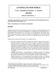
The commissioning of a PCD is illustrated using stairway lighting as an example. The
building has a ground floor and three upper storeys. Each level has a push-button for
switching the lights on. By briefly pressing any of these buttons, all 4 lights in the
stairway will be switched on for a period of 5 minutes.
The push-buttons are connected to the 4 inputs of the PCD: I0, I1, I2 and I3.
The 4 lights are switched on/off via a relay. The relay is controlled via a single output
(O32) on the PCD.
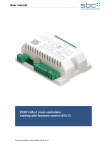
1.2.2
Connection diagram of PCD2.M480
3rd floor
2
rd
floor
1rd floor
Ground floor
N
I0
I3
PCD2.E110
0
P
O32
I/O addresses
230 VAC
PCD2.A400
16
32
48
Base addresses
+
Battery
PCD2.M480
24 VDC
Battery
WD
–
–
+
+
+
112
+
96
~
230 VAC
=/~
Cable PCD8.K111
RUN
HALT
ERROR
Base addresses
–
24 VDC
PG5
PGU
29
:
:
:
:
:
:
:
20
~
PG5-WorkShop I Chapter 1 I Quick Start I 23.01.06
80
64
1-5
Saia-Burgess Controls Ltd.
1.2.3
PCD2.M480 equipment
1. Insert the supplied 3.0 V lithium battery.
2. Plug a PCD2.E110 module into socket 1 (addresses 0 to 15).
3. Push the module towards the middle of the device until the end stop and
engage latch. This provides 8 digital inputs for 24 VDC with addresses I0 to
I7. Only inputs I0 to I4 will be used.
4. Plug a PCD2.A400 module into socket 3 (addresses 32 to 47) as previously
described. This provides 8 digital outputs (O32 to O39) for 24 VDC / 0.5
A.Only output O32 will be used.
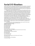
1.2.4
Wiring
1. Connect the 24 VDC supply to screw terminals 20 (+) and 23 (–) .The
following supply voltages are allowed: 24 VDC ±20% smoothed or 19 VAC
±15% full-wave rectified
2. The four inputs used are connected according to the hardware description of
the PCD2.E110 module. Connect the 4 push-button switches to terminals 0 to
3. Terminals 8 and 9 are connected to the power supply negative.
st
3 floor
st
2 floor
st
1 floor
Ground floor
+24 VDC
–
0 1 2 3 4 5 6 7 8
E0 E1 E2 E3 E4 E5 E6 E7 L
9
–
+ Module base address (=0 for this example)
3. Connect terminal 0 to the relay coil , terminal 8 to the 24 VDC supply positive,
and terminal 9 to the supply negative.
3rd floor
2rd floor
1rd floor
Ground floor
+24 VDC
–
230 VAC
N
P
0 1 2 3 4 5 6 7 8
A0 A1 A2 A3 A4 A5 A6 A7 +
9
–
+ Module base address, , (+32 for this example)
4. Connect the PC’s RS 232 interface (COM port) to the PCD’s PGU connector.
PCD8.K111 cable should be used for this purpose.
N.B: For more detailed information about hardware assembly and wiring, please
refer to your PCD hardware manual.
PG5-WorkShop I Chapter 1 I Quick Start I 23.01.06
1-6
Saia-Burgess Controls Ltd.
1.3
Editing the program
1.3.1
Software Installation
Install the PG5 programming tool for SAIA®PCD on the PC (if this has not already
been installed), following the instructions supplied with the CD
(cd:\PG5\ InstallationGuide_E.htm).
1.3.2
Starting the PG5
Start the PG5's Project Manager:
Start --> Programs --> SAIA PG5 V1.4 --> Project Manager
1.3.3
Opening a new project
Before starting to write a new program, a new or existing project must be opened that
contains the necessary definitions, a few configuration parameters and the files
needed for the user program.
If the project does not yet exist, select Project, New…, define the name of the new
project in the Project Name field, check the Create CPU option and confirm with the
OK button.
Make a new project
Enter project name
Check Create CPU
Confirm with OK
PG5-WorkShop I Chapter 1 I Quick Start I 23.01.06
1-7
Saia-Burgess Controls Ltd.
Project Folder
Common Files Folder
CPU Folder
The SAIA Project Manager window is already displayed. The Project window shows
the structure of the new project. (If this window is not yet displayed, use the View,
Project Tree menu command).
Folders in the Project window contain project information, which is arranged
according to certain criteria:
The name of the main folder shows the project name and the number of CPUs
used in the project.
Modules that are shared by several the CPUs can be stored in the Common
Files folder.
Next are the CPU folders (each CPU corresponds to a PCD).
Every CPU folder contains the following sub-folders:
Settings, contains the configuration for the programming tool and the PCD.
Program Files, contains the program module files.
Listing Files, contains files generated during the program build (Build). They are
of less interest to the inexperienced user.
Opening an existing project
A project that already exists can be opened using the Project, Open… menu
command. This searches for all project files (.5pj) in the project directory, and
displays them in a list. Double-click on the project in the list, or select the project from
the list and press the Open button. Alternatively, press the Browse button and find the
Project or CPU file directly.
PG5-WorkShop I Chapter 1 I Quick Start I 23.01.06
1-8
Saia-Burgess Controls Ltd.
1.3.4
Configuration
Before you can work with a CPU in the project, configuration parameters must be
defined, so that the programming tools and the generated user program will work with
the PCD.
Under Online settings parameters can be set for communication between the PC and
the PCD. Several possibilities are available. For this exercise the default protocol
(PGU) will be selected, followed by the PC's serial port number (COM1).
Channel PGU (RS 232)
Select PGU protocol
Click on Setup
Select the PC’s serial
port RS232 to be
connected to the PCD
Channel S-Bus USB
Define S-Bus USB
protocol
Select
PGU
PG5-WorkShop I Chapter 1 I Quick Start I 23.01.06
Note:
The USB interface is only available for
the new CPUs: PCD2.M480 and PCD3
1-9
Saia-Burgess Controls Ltd.
The PCD is configured using Hardware Settings. In this example, the options
Memory, S-Bus, Gateway, Modem and Password are not required. However, it is
important to select the correct PCD type and size of memory fitted. The PCD2.M480
is always supplied with a standard 1024 Kbyte RAM.
Select PCD type
With certain PCD types a setting is
required for the user memory
equipped
Click Download… button
Download all parameters
to the PCD
Check Memory Allocation
too
PG5-WorkShop I Chapter 1 I Quick Start I 23.01.06
1-10
Saia-Burgess Controls Ltd.
1.3.5
Adding a program file
PCD user programs are stored in one or more files. There are several ways of adding
a program file:
In the Project window, select Program Files, click the right-hand mouse button to
display the context menu and select New… (new file).
Alternative methods:
Click on the New File button on the toolbar, or use the File, New… menu command.
In the New File window the name and type of the module are defined: two very
important items of information.
A number of editors are available for
writing PCD user programs.
The user can choose which editor is
best suited to the user program.
For this example it is
Fupla File (*.fup).
Fupla
is
a
general
purpose
programming language.
File name of
user program
User program file
type
Check Linked for this
example
PG5-WorkShop I Chapter 1 I Quick Start I 23.01.06
1-11
Saia-Burgess Controls Ltd.
1.3.6
Opening a file
If the folder already contains a program file, the file can be opened as follows:
In the Project window, open the Program Files folder and double-click on the relevant
file. Alternatively, right-click on the file name to open the context menu and select
Open.
Open file
Mark file or open it
by double-clicking
the mouse button
1.3.7
Editing a program
Input
Symbols
Output
symbols
User
programs
Symbol-Editor
(used symbols)
PG5-WorkShop I Chapter 1 I Quick Start I 23.01.06
1-12
Saia-Burgess Controls Ltd.
Editing symbols
Symbols reference the data needed by the PCD's user program, e.g. the stairway
lighting switches. We edit symbols in the connectors on the Fupla page. ‘Read’
symbols are on the left, ‘write’ symbols are on the right.
This stairway lighting example has 4 light switches as inputs (I 0, I 1, I 2 and I 3) and
one output (O 32) to drive the stairway lights. The required period of 5 minutes, during
which stairway lighting will be on, must be entered in the input connector as a multiple
of tenths of a second.
The value of this constant is therefore 3000 (5 min. x 60 sec. x 10 = 3000).
Place
Connectors
To add a connector and its symbol to a Fupla page, press the toolbar button Place
Connector and position the mouse on the Fupla page. A ‘read’ input connector is
added by clicking the left-hand mouse button. A ‘write’ output connector is added by
holding down the Shift key and pressing the left-hand mouse button. The connector
you have just added is ready to receive a symbol and a cursor is displayed inside the
connector. If you do not wish to edit the symbol inside the connector straight away,
press the ESC key and place the next connector.
To edit or modify a connector symbol already present on the Fupla page, select the
connector by double clicking quickly. A cursor will be displayed inside the connector.
It is now possible to enter the address I 0 to I 3, or output O 32, or the constant. Make
sure you always leave a space between the letter I and the input address. The same
applies for the output.
To edit the input symbols, 4 consecutive cells in the left-hand column of the program
screen are marked with the mouse and addresses I 0 to I 3 are entered. The time
constant 3000 (left) and output O 32 (right) are entered in the same way.
Show/Hide
Symbol Editor Please note that the address type (I or O) and address value (0 to 3 and 32) must be
separated by a space character.
The symbols will immediately appear in the Symbols window of the Symbol Editor. If
the symbol editor is not visible it can be displayed using the View, Symbols menu
command or by pressing the Show/Hide Symbol Editor toolbar button:
Note:
As a default, each new page may already provide margins with connectors on the left
and right. If you prefer new pages not to appear with these connectors, so that you
can place them yourself at your own convenience, please deactivate the
corresponding option with menu: View, Options…, Add Empty Side Connectors.
To remove any empty connectors present on the left or right of the page, select
menu: Page, Remove Empty connectors.
To place connectors once again on a blank page, select menu: Page, Add Empty
Side Connectors.
PG5-WorkShop I Chapter 1 I Quick Start I 23.01.06
Saia-Burgess Controls Ltd.
Editing program functions
Program functions are entered in the area between the ‘read’ and ‘write’ connectors.
This is done by positioning the graphical symbols of the function boxes (FBoxes) that
are used to create user programs.
Function boxes are selected from the FBox Selector window.
Add Fbox
The first function required in this example serves to switch on the lighting in response
to a short pulse from a stairway switch. This is an OR function, which is found in the
Binary family in the Standard library.
The second function Off delay defines the 5 minute period during which the lights are
on. It is found in the Timer family in the Standard library.
Further information on the chosen FBox can be found by right-clicking on the function
in the FBox Selector window, and choosing the FBox Info context menu command.
When a function box has been selected from the FBox Selection window, the lefthand mouse button is used to place it in the edit window between symbol columns.
With certain function boxes, such as OR logic, the number of inputs can be selected.
This is done by dragging the mouse vertically and clicking the left-hand mouse button
when the number of inputs is correct.
PG5-WorkShop I Chapter 1 I Quick Start I 23.01.06
1-13
1-14
Saia-Burgess Controls Ltd.
Connecting function
Use this method when connection points are aligned horizontally
1.
2.
3.
4.
Press the Select Mode button
Place the mouse pointer over the FBox and press
the left-hand mouse button.
Hold the button down and drag the FBox
horizontally until the connection is made. Do not
release the mouse button.
Drag the FBox back to its original position and
release the mouse button.
1.
2.
3.
4.
Use this method for the other connections
1.
Press the Auto Lines Mode button
2.
Click on the starting point with the left-hand mouse
button and release it. Move the mouse pointer to
the right as far as required and press the left-hand
mouse button again.
3.
Move the mouse vertically and click the left mouse
button once more.
4.
Move the mouse pointer to the FBox connector and
press the left-hand mouse button again to finalise
the connection.
5.
If necessary, line drawing can be aborted by
pressing the right-hand mouse button.
Deleting a line, function box, symbol or connector
Press the Delete Mode toolbar button and click on the
line, FBox, Symbol or Connector to be deleted.
PG5-WorkShop I Chapter 1 I Quick Start I 23.01.06
1.
2.
3.
4.
Saia-Burgess Controls Ltd.
1.4
Running and testing the program
1.4.1
Building the program (Build)
Before the program executed by the PCD, it must be build (compiled, assembled and
linked) using the Project Manager's CPU, Rebuild All Files menu command, or the
Rebuild All Files toolbar button.
Rebuild
All Files
The results of the build are shown in the Messages window (Compiling, Assembling,
Linking etc.). If the program has been correctly edited, the build function completes
with the message: Build successful. Total errors 0 Total warnings: 0
Errors are indicated by a red error message. Most errors can be located in the user
program by double-clicking on the error message.
1.4.2
Downloading the program into the PCD (Download)
The user program is now ready. All that remains is to download it from the PC into the
PCD. This is done using Project Manager's Download Program toolbar button or the
Online, Download Program menu command.
If any communications problems arise, check the configuration settings (Settings
Online and Settings Hardware) and the (PCD8.K111 or USB) cable connection
Download between the PC and the PCD.
Program
PG5-WorkShop I Chapter 1 I Quick Start I 23.01.06
1-15
1-16
Saia-Burgess Controls Ltd.
1.5
Finding and correcting errors (Debugging)
The first version of a program is not always perfect. A stringent test is always needed.
Program testing is done using the same editor that was used to write the program.
1. Press the Go On /Offline button
2. Start program with the Run button
Observe the RUN LED on the PCD at the same time.
When the Run button is pressed, the RUN LED on the PCD should turn on because
the PCD is now executing the user program.
When the Stop button is pressed, the RUN LED on the PCD should turn off because
the PCD has stopped executing the program.
When the editor is Online and the PCD is in RUN mode, the state of each individual
symbol can be displayed:
The logical state of binary data is shown with a heavy or fine line (heavy = 1 and
fine = 0)
Other data values can be displayed by clicking the left-hand mouse button on the
connection to show a Probe window: use the mouse to select the Place Probe
button and the link.
PG5-WorkShop I Chapter 1 I Quick Start I 23.01.06
Saia-Burgess Controls Ltd.
1.6
Correcting a program
To modify a program, proceed as follows:
1. Go offline (using the Go On /Offline button).
2. Modify the program.
3. Execute a new program build (with the Build button).
4. Download program to the PCD (with the Download Program
button))
PG5-WorkShop I Chapter 1 I Quick Start I 23.01.06
1-17
1-18
Saia-Burgess Controls Ltd.
PG5-WorkShop I Chapter 1 I Quick Start I 23.01.06
Saia-Burgess Controls Ltd.
Contents
2
2.1
PROJECT MANAGEMENT ......................................................................... 3
Introduction ....................................................................................................................................3
2.2
Project organization .......................................................................................................................4
2.2.1
Example of application project.................................................................................................4
2.2.2
Saving the project to a PC ........................................................................................................6
2.2.3
Compressing a project or CPU .................................................................................................6
2.2.4
Opening a project .....................................................................................................................7
2.2.5
Creating a new project..............................................................................................................7
2.3
The Project window ........................................................................................................................8
2.3.1
Project folder ............................................................................................................................8
2.3.2
Common Files folder ................................................................................................................9
2.3.3
CPU folder................................................................................................................................9
2.3.4
Settings Online .......................................................................................................................10
2.3.5
Connection of PC to PCD.......................................................................................................11
2.3.6
Hardware Settings ..................................................................................................................12
2.3.7
Software Settings....................................................................................................................17
2.3.8
Program Files folder ...............................................................................................................19
2.3.9
File types ................................................................................................................................20
2.3.10 Files linked .............................................................................................................................21
2.3.11 Common files .........................................................................................................................21
2.4
Building the program ...................................................................................................................22
2.4.1
Rebuild All and Build..............................................................................................................23
2.4.2
Build options...........................................................................................................................23
2.5
Messages window..........................................................................................................................24
2.6
Downloading the program into the PCD ....................................................................................25
2.6.1
Download options...................................................................................................................26
2.6.2
Load program onto backup memory (Flash card)...................................................................27
2.6.3
Backup memory and transfer of the application program.......................................................27
2.7
View window .................................................................................................................................27
2.7.1
Organization block structure...................................................................................................27
2.7.2
List of organization blocks .....................................................................................................28
2.7.3
List of symbols .......................................................................................................................28
2.7.4
Cross-Reference .....................................................................................................................28
2.8
Program backup ...........................................................................................................................29
2.9
Self downloading files...................................................................................................................30
2.9.1
Prepare a '.sd5' file..................................................................................................................30
2.9.2
Downloading a '.sd5' file ........................................................................................................31
PG5-WorkShop I Chapter 2 I Project management I 23.01.06
2-1
2-2
Saia-Burgess Controls Ltd.
PG5-WorkShop I Chapter 2 I Project management I 23.01.06
Saia-Burgess Controls Ltd.
2
Project management
2.1
Introduction
Modern automation applications frequently comprise large numbers of controllers
connected in networks. The PG5 therefore unites in a single project the programs and
configurations of all PCD controllers within any one application. The PG5 Project
Manager offers the user a global view of all the information that relates to a project.
PG5-WorkShop I Chapter 2 I Project management I 23.01.06
2-3
2-4
Saia-Burgess Controls Ltd.
2.2
Project organization
2.2.1
Example of application project
In practice, automated installations almost always comprise a number of local PCD
programmable controllers connected in a communications network. Each PCD
supports the control of a particular function within the project as a whole, such as:
lighting management, heating control, ventilation control, or the automatic doors of an
underground garage.
Project : City Hall
CPU: lighting management
Network
CPU: garage
doors
CPU: ventilation
control
CPU: heating
control
The PG5 programming tool unites in a single PG5 project all the PCD CPUs that
belong to any one particular application.
A green triangle identifies the active
CPU. All instructions for building,
downloading and testing the program
use the configuration and program
files of the active CPU.
Active CPU
PG5-WorkShop I Chapter 2 I Project management I 23.01.06
Saia-Burgess Controls Ltd.
Project Manager has three windows:
Project Tree
Message Window
The Project window shows the structure of the project with the PCD CPUs that make
it up. To display this window, select menu path: View, Project Tree, or click on the
Project Tree button.
The Message window shows alarm and error messages generated during any build of
the program. To display this window, select menu path: View, Message Window, or
click on the Message Window button.
The View window shows the View list, block list, block structure or text files. It also
allows symbols to be cross-referenced.
PG5-WorkShop I Chapter 2 I Project management I 23.01.06
2-5
2-6
Saia-Burgess Controls Ltd.
2.2.2
Saving the project to a PC
By default, projects are saved in directory C:\PG5 Projects 1_4
The project is saved in a directory
bearing the same project name. It
uses one subdirectory per CPU.
File, Backup
File, Restore
2.2.3
Compressing a project or CPU
When a project is saved, the entire structure of directories and the files they contain
must be preserved. The simplest method is to compress the whole structure into a
*.ZIP file using the Backup command. This is supported as follows:
Select project file or
one of the CPUs
Select menu command Project, Backup1
Compress project or
one of the CPUs
Select *.zip file of
project or CPU
1
The Project, Restore menu command lets you restore a project/CPU that has been saved in a *.ZIP file.
PG5-WorkShop I Chapter 2 I Project management I 23.01.06
2-7
Saia-Burgess Controls Ltd.
2.2.4
Opening a project
The PG5 is delivered with all the examples in this manual included. The Project,
Open… menu command allows you to open them and try them out.
An existing project can be opened with command Project, Open…,
This locates all the project files (.5pj) in the projects directory and displays them in a
list. Double-click on one of the projects in the list or select a project and press the
Open button. Alternatively, press the Browse button and look for the project file (.5pj)
or CPU file (.5pc) directly.
Directory of saved projects
Select a project
2.2.5
Creating a new project
To create a new project, use menu command Project, New…, define the name of the
new project in the Project Name field, select the Create CPU option and confirm with
the OK button.
Name of new project
Brief description of contents
PG5-WorkShop I Chapter 2 I Project management I 23.01.06
2-8
Saia-Burgess Controls Ltd.
2.3
The Project window
Projekt
Tree
Folders in the Project window group together project information according to certain
organizational criteria:
2.3.1
Project folder
The main folder shows the project with its name and how many CPUs it includes. To
modify information in this folder, select the folder with the mouse and show the
context menu with the right-hand mouse button.
New CPU…
Import CPU…
Paste CPU
Copy Project…
Backup…
Restore…
Adds a new CPU to the project
Imports CPUs from another PG5 project or from an
old PG4 project
Pastes a CPU with all its contents
Copies a project with all its contents
Backs up the project to a *.zip file
Restores the project from a *.zip file
Rebuild All CPUs
Online Commands
Print…
Find…
Commands for implementing a full project Build or
Download.
Properties
Modify information specific to the project folder:
project name, description, …
PG5-WorkShop I Chapter 2 I Project management I 23.01.06
2-9
Saia-Burgess Controls Ltd.
2.3.2
Common Files folder
The Common Files folder is provided to hold modules common to more than one
CPU in the project. To add a program file, select the folder and use New File from the
context menu.
The Add Files item in the context menu can be used to import any type of PG5
program file, but can also import the application's commissioning and maintenance
documents (in Word, Excel, etc.). These files are stored with the PG5 project and can
be opened by double-clicking on them.
Note
Common files use the same local symbols in each CPU which uses the file, but the
CPU's own Global symbols are used, so global symbols used in a common file can be
different for each CPU.
2.3.3
CPU folder
Each CPU folder contains the configurations and programs for one controller in the
project. To modify information in a CPU folder, right-click on it to show the context
menu.
Set Active
Rebuild Changed files
Rebuild All Files
Go Online
Download Program
Download Hardware Settings
Online Configurator
Online Debug
Data Transfer
Copy, Paste
Delete
Print…
Properties
When a CPU is selected in the Project window, this
command will make it the active CPU. The active
CPU is identified by a green triangle. All commands
from menus and buttons work with the active CPU.
Commands for doing a Build of the CPU selected in
the Project window.
Copies, pastes or deletes the CPU selected in the
Project window
Modify information specific to the CPU folder: CPU
name, description, …
Note: From the menu: Tools, Options, General page, the option Activate CPU
according to Project Tree location is selected, the SAIA Project Manager will
automatically activate the CPU according to the context in which it is used. The Set
Active command cannot then be used and does not appear in the context menu.
PG5-WorkShop I Chapter 2 I Project management I 23.01.06
2-10
Saia-Burgess Controls Ltd.
2.3.4
Settings Online
The Settings, Online folder allows the CPU's communications parameters to be
defined. A number of communications protocols are supported: PGU, S-Bus,
Ethernet, etc. However, only the PGU and S-Bus USB protocol allows direct
communication with the PCD that does not require configuration in the PCD's
Hardware Settings.
Channel PGU (RS 232)
Press button
Define serial port RS232
of computer
Define PGU
protocol
Channel S-Bus USB
Define S-Bus USB
protocol
Ckeck PGU
PG5-WorkShop I Chapter 2 I Project management I 23.01.06
Note:
The USB interface is only available for
the PCD2.M480 and PCD3
2-11
Saia-Burgess Controls Ltd.
2.3.5
Connection of PC to PCD
Channel PGU (RS 232)
A PCD8.K111 cable provides the RS 232 link between the PC and the PCD. For
more information about this cable, please see the PCD hardware manual.
PCD8.K111
Channel S-Bus USB
The USB interface is only available for the CPU PCD2.M480 and PCD3
Online
Configurator
Checking the connection
The Online Configurator button, or the Tools, Online Configurator menu command
allows the connected PCD's settings to be viewed. If the information in red is shown,
then communications is working perfectly.
If not, the "No response" error
message will be displayed. Check
the Online Settings and the cable.
PG5-WorkShop I Chapter 2 I Project management I 23.01.06
2-12
Saia-Burgess Controls Ltd.
2.3.6
Hardware Settings
The Hardware Settings folder allows definition of the PCD controller's memory and
communications parameters.
When a controller is used for the first time, or after adding new memory to the PCD,
its memory must be configured. There are two ways of selecting the parameters of
the above window:
The first way is to select the Upload button and read View directly from the
controller.
The second way is to define the window's information with the help of the tables
shown on the next two pages. The above example corresponds to the lines
marked in bold on these tables.
PG5-WorkShop I Chapter 2 I Project management I 23.01.06
2-13
Saia-Burgess Controls Ltd.
The table below shows information about
the memory jumpers. These jumpers must
be set on the PCD's CPU card. For more
information, please see the hardware
manual.
Memory jumpers in a PCD2.M120
equipped with LM621024 memory
PCD type
Memory
PCS1.C8
Flash 2 MBit
Flash 4 MBit
PCD1. M110 Empty space
/120/150
1 RAM 256 kBit
1 RAM 1MBit
1 Flash 1MBit
1 EPROM 512kBit
1 EPROM 1Mbit
PCD2.M110 Empty space
/120/150
1 RAM 256 kBit
1 RAM 1 Mbit
1 RAM 4 MBits
1 Flash 1 MBit
1 Flash 4 MBit
1 EPROM 512 kBit
1 EPROM 1 MBit
1 EPROM 4 MBit
PCD4.M
1)
2)
2 RAM 62256
2 RAM 1 Mbit
2 EPROM 256 kBit
2 EPROM 512 kBit
2 EPROM 1 MBit
Stock
number
2)
4 502 7013 0
4 502 7175 0
4 502 7141 0
4 502 7224 0
4 502 3958 0
4 502 7126 0
4 502 7223 0
Extension
Memory Size
(RAM)
240 kByte 128 kByte
1008 kByte 896 kByte
17 kByte
32 kByte
128 kByte
112 kByte
64 kByte
128 kByte
4 502 5414 0
4 502 7013 0
4 502 7141 0
4 502 3958 0
4 502 7126 0
4 502 5414 0
Jumper
Code/Text
Memory Size
32/128 kByte 1)
32 kByte
128 kByte
512 kByte
112 kByte
448 kByte
64 kByte
position on
PCD
No carriers
No carriers
None
13 kByte
13 kByte
13 kByte
13 kByte
13 kByte
R
R
R
E
E
E
None
1)
24/128 kByte
24/128 kByte 1)
24/128 kByte 1)
24/128 kByte 1)
24/128 kByte 1)
24/128 kByte 1)
24/128 kByte 1)
128 kByte
24/128 kByte 1) E ,<=1Mbit
512 kByte
E , >1Mbit
4 502 5414 0
4 502 7013 0
4 502 5327 0
4 502 3958 0
4 502 7126 0
64 kByte
256 kByte 172 kByte, for
64 kByte memory
128 kByte PCD7.R310
256 kByte
128 kByte for all PCD2.M110/120 with hardware versions J or higher, 128 kByte for all PCD2.M150
1008 kByte for all PCS1 hardware version bigger or equal to E
Jumpers: R= RAM, E = EPROM, F = Flash
PG5-WorkShop I Chapter 2 I Project management I 23.01.06
R ,<=1Mbit
R ,<=1Mbit
R ,<=1Mbit
R , >1Mbit
F ,<=1Mbit
F , >1Mbit
E ,<=1Mbit
RAM
RAM
E256
E512
E1M
2-14
Saia-Burgess Controls Ltd.
If the PCD's memory size is unknown, find the reference printed on the memory chip
itself and use the table below to determine the stock number and memory size:
Memory Size
Order Number
Reference
RAM 256 kBit
4 502 5414 0
SRM 2B256SLCX70
HY62256ALP-70
GM76C256CLL-70
M5M5256DP-70LL
TC55257DPL-70L
RAM 1 MBit
4 502 7013 0
BS62LV1025 PC-70
LP621024D-70LL
SRM20100LLC70
HY628100ALP-70
GM76C8128CLL-70
M5M51008BP-70L
TC551001BLP-70L
RAM 4 MBit
4 502 7175 0
BS62LV4006PC P55
BS62LV4007PC P55
HM628512LP-5
KM684000ALP-5L
KM684000BLP-5L
Flash 1 MBit
4 502 7141 0
AM29F010-70PC
Flash 4 MBit
4 502 7224 0
AM29F040 auf Sockel
EPROM 256 kBit
4 502 5327 0
UPD27C256AD-10
M27C256B-10F1
TMS27C256-10JL
EPROM 512 kBit
4 502 3958 0
AM27C512-15XF1
AMC27C512-15XF1
AM27C512-90DC
UPD27C512D-10
M27512-10XF1
M27512-10F1
EPROM 1 MBit
4 502 7126 0
AM27C010-90DC
NM27C010Q-90
M27C1001-10F1
EPROM 4 MBit
4 502 7223 0
AM27C040-100DC
M27C4001-10F1
PG5-WorkShop I Chapter 2 I Project management I 23.01.06
2-15
Saia-Burgess Controls Ltd.
Code/Text/
Extension Memory
Size
(RAM)
1024 kByte
PCD Type
PCD4.M170
PCD2.M170
PCD2.M480
Internal memory External memory
backup
backup
(Flash )
Aucune
(Flash )
PCD7.R400 - 1024 kByte
PCD3.M3020P
128 kByte
CD3.M3120
128 kByte
PCD3.R500 - 128 kByte
PCD3.M3230
PCD3.M3330
256 kByte
PCD3.R500 - 256 kByte
256 kByte
PCD7.R500 - 512 kByte
PCD3.M5440
PCD3.M5540
PCD3.M6340
PCD3.M6540
256 kByte
512 kByte
New PCD systems support internal or external backup memory: PCD7.R400/R500
(optional).
Backup memory lets you save a RAM copy (code/text/extension) of the application
program to flash memory, where none of the contents will be lost on a power cut or
faulty battery.
We recommend that you use the backup memory on your PCDs to protect yourselves
against any undesirable loss of data.
If the RAM application program (code/text/extension) is corrupted, a PCD coldstart will
automatically restore the program from backup memory.
PCD7.R400
PCD7.R500
External backup memory also lets you transfer applications from one PLC to another,
and create a RAM store of texts and DBs in extension memory while the PLC is running
(address ≥ 4000).
Note:
Regardless of any storage in backup memory, you must still backup the project's source
files. The source files are not stored in the PCD's memory.
PG5-WorkShop I Chapter 2 I Project management I 23.01.06
2-16
Saia-Burgess Controls Ltd.
24 K Lines =
4* 24 K Bytes
Available memory:
24*4+32 shared
between code and
text/DBs of each CPU
Extension memory,
shared among CPUs
Available memory defined on the PCD page is shared between the program's code
and text in each CPU. Some PCDs have more than one CPU: PCD4.M44x and
PCD6.Mxxx.
For a single CPU, this is defined automatically according to the user program, so
Manual Memory Allocation can remain unchecked.
Default parameters are adequate for most applications. In applications where they are
not, an error message like this will appear when downloading the program to the
PCD:
There are several ways around this error:
Uncheck Manual Memory Allocation and let the PG5 do the code/text partitioning,
if there's enough memory.
Check Manual Memory Allocation and configure the memory allocation according
to the error message.
Increase PCD memory capacity.
When the Hardware Settings have been defined, always remember to download them
into the PCD by pressing the Download button, or using the Online, Hardware
Settings, Download menu command.
PG5-WorkShop I Chapter 2 I Project management I 23.01.06
2-17
Saia-Burgess Controls Ltd.
2.3.7
Software Settings
This window allows the user to reserve address ranges for registers, counters, timers
and dynamic flags. During the program build, these addresses are automatically
assigned to dynamic symbols defined by the user program and Fupla FBoxes.
A dynamic symbol is one for which no absolute address has been defined:
Dynamic symbol
It is not always necessary to change the dynamic addresses. The default settings are
usually adequate for most applications.
However, if an error message like this appears during the build of a large program:
Fatal Error 368: Auto-allocation/dynamic space overflow for type: R
then it will be necessary to extend the dynamic address range for the media type
shown in the error message.
If the controller is equipped with EPROM or Flash memory, the RAM Texts and RAM
View Block dynamic ranges will also have to be configured to addresses from 4000
upwards, so that these Texts and DBs will be in writeable RAM memory.
PG5-WorkShop I Chapter 2 I Project management I 23.01.06
2-18
Saia-Burgess Controls Ltd.
PCDs are configured with 31 timers, some of which have their addresses assigned
dynamically. With certain programs it may be necessary to increase the number of
timers.
The timebase at which timers decrement is once every 0.1 seconds (100ms). If
necessary this can be set to another value. Note that the timebase has no influence
on Fupla programs. Only IL programs are affected by this parameter.
It is advisable not to define an unnecessarily large number of timers, nor an
unnecessarily small timebase. This will help speed up program cycle times.
By default, all flags are nonvolatile. If necessary, the Last Volatile Flag parameter
allows a volatile range to be defined. (This example defines volatile flags for
addresses F 0 to F 2999.) Volatile flags are always set to 0 at start-up, nonvolatile
flags retain their values.
PG5-WorkShop I Chapter 2 I Project management I 23.01.06
2-19
Saia-Burgess Controls Ltd.
2.3.8
Program Files folder
This folder holds the files that make up the CPU's program. To modify files in a
program folder, right-click on the folder or file to show the context menu.
Adds a new program
file
Imports a file from
another project or CPU
Copy/paste program
files between CPUs
in the project
View or edit the file
name, description and
link option
Linked or not linked
If a new file is added to the program folder, define the file name and type.
File name
Define the type of editor
according to the list
below
Brief description of the module
PG5-WorkShop I Chapter 2 I Project management I 23.01.06
2-20
Saia-Burgess Controls Ltd.
2.3.9
File types
A CPU can have several program files of different types. Each type of file has a
corresponding editor specific to a field of application.
Instruction list editor (*.src)
Allows programming in text form with a set of 127
instructions. Suitable for all applications, but
requires a certain amount of programming
experience.
Fupla editor (*.fup)
Allows programs to be drawn in the form of
function plans and contact diagrams. Requires no
programming experience. Many libraries are
available for the rapid implementation of HEAVAC
applications and communications networks
(modem, Lon, Belimo, EIB, etc.).
Graftec editor (*.sfc)
This is a tool for structuring programs in IL
(instruction list) and Fupla. Particularly suitable for
sequential applications with waits for internal or
external events.
It is the ideal tool for programming machines with
commands for motors, actuators, etc.
HMI editor
Allows configuration of dialogue with PCD7.D1xx et
PCD7.D2xx terminals (installed in addition to PG5)
S-Net editor (*.dp, *.lon, *.rio)
Supports configuration of communications networks:
Profibus DP, LON and SRIO.
PG5-WorkShop I Chapter 2 I Project management I 23.01.06
COB
STH
DYN
INC
ECOB
0
0
I 0
F 9
C 53
2-21
Saia-Burgess Controls Ltd.
2.3.10 Files linked
Right-click on the file and
select Linked on the
context menu
Files represented by this icon with an arrow are linked together to form the program,
and are downloaded into the PCD's memory.
Files represented by this icon without an arrow are not part of the program. They files
are ignored and are not downloaded to PCD memory.
This can be useful for modules which are linked for commissioning tests, but which
should not be present in the final program.
2.3.11 Common files
Mark file, hold lefthand mouse
button down.
Drag mouse over
program folder.
Files in the Common Files folder can be copied, pasted or just dragged into the
program folder of the CPU that uses them. Note the two dots at the start of the copied
or dragged file name. This path means that the file is in a folder which is one level up.
The file can be edited from the common files folder, or from the program files folder of
the CPU. In either case, the user is modifying the same file and corrections will apply
for all CPUs linked to it.
PG5-WorkShop I Chapter 2 I Project management I 23.01.06
2-22
Saia-Burgess Controls Ltd.
2.4
Building the program
The PCD cannot process programs directly after editing in Fupla, IL, Graftec, S-Net or
HMI. Files must first be prepared using the different stages set out in this diagram:
Source files :
Graphical programs
1. Compile
Rebuild all
or
Build
Instruction list programs
2. Assemble
Printer
Object and listing files
3. Link
PCD file
Download
program
PCD controller
4. CPU, Create Documentation command
Printer
1. Compilation converts graphical files into instruction list files (*.fbd, *.src, *.hsr)
2. Assembly produces binary object files (*.obj), and an assembly report (*.lst) which
can be printed or used for troubleshooting certain assembler errors.
3. Linking combines object files (*.obj) to form a single executable file (*.pcd) for
downloading into the controller.
4. Documentation can be generated with the Project Manager's CPU, Create
Documentation menu command. The result will be available in the Documentation
Files folder.
PG5-WorkShop I Chapter 2 I Project management I 23.01.06
Saia-Burgess Controls Ltd.
2.4.1
Rebuild All and Build
Le button, menu CPU, Rebuild all Files, starts the compilation, assembly and linkage
of all files linked for the active CPU.
Rebuild
All Files
The button, menu CPU, Build Changed Files does the same job, but only for files
which have been modified since Build Changed Files or Rebuild All Files. This saves
time when building large programs.
Build
Changed
Files
2.4.2
Build options
More can be done by setting the build options with the menu command Tools,
Options:
Ask before saving changed files before a build
If selected, the PG5 requests authorization to save source files which have been
changed but not saved before building the program. Otherwise files will be saved
automatically.
Stop build on first error
Selecting this option will stop the build when the first error appears in the Messages
window.
Download program after successful build
Selecting this option automatically downloads the program to the PCD, but only if the
build ends with no errors.
Download without confirmation
Normally the process of downloading the program to PCD memory starts with a dialog
box notifying the user and to be acknowledged with an OK button. Selecting this
option downloads the program directly, without displaying the dialog box.
Clear Message Window on build
The Messages window will be cleared at the start of each build.
Create listing file
Creates an assembly report (*.lst)
Create map file
Creates a file showing with the memory space taken up by the application and a list of
the global symbols.
PG5-WorkShop I Chapter 2 I Project management I 23.01.06
2-23
2-24
Saia-Burgess Controls Ltd.
2.5
Messages window
The Messages window provides information on the progress of a program build. It
notes the different stages of the build: compilation, assembly and linkage. If the
program has been edited correctly, the build ends with the message: Build
successful. Total errors 0 Total warnings: 0
Any errors will be indicated with a message in red. Double-clicking with the mouse on
these messages generally enables the error to be located in the application program.
Double-click with
the mouse on the
error message
The error is marked
in red or with an
arrow
Correction of
error
PG5-WorkShop I Chapter 2 I Project management I 23.01.06
Saia-Burgess Controls Ltd.
2.6
Downloading the program into the PCD
If the build concludes without any error messages, the Download Program button or
the Online, Download Program menu command can be used to load the program into
Download the PCD's memory.
Program
Program File Name
By default this is the name of the program for the active CPU.
All
Downloads the entire program (Code Segment, Text/DB Segment, Extension Memory
Segment)
Changed Blocks
Only downloads blocks (COB,PB,FB,SB,ST,TR,XOB) modified since the last
Download. This option is only used to save time with minor program corrections. The
Changed Blocks button can be used to display a list of changed blocks.
Download in Run
Allows changed program blocks to be downloaded without halting program execution.
Proper operation of this option may depend on the corrections being made to the
program.
Selected Segments
Only downloads segments defined under Selected Segments:
Code Segment = Program, Text/DB Segment = Text and DB 0…3999, Extension
Memory Segment = Text and DB 4000…7999.
First-time Initialisation Data Only
Only downloads the Data described below.
First-time Initialisation Data
This option authorizes the initialisation of certain Datas during a program build. Datas
initialised by the program download are defined as follows:
symbol type address := initialisation_value
Datas not initialised with the program download can be initialised at every coldstart by
code in XOB16.
PG5-WorkShop I Chapter 2 I Project management I 23.01.06
2-25
2-26
Saia-Burgess Controls Ltd.
2.6.1
Download options
Download options can be defined with the Tools, Options menu command, or the
Options button on the Download Program dialog box. They allow the program
download procedure to be personalized.
Download program only if changed
These define the default settings for the Download Program dialog box, see previous
page.
Download only the changed Blocks
See previous page.
Verify all PCD memory writes
All View written to the PCD will be read back and compared. This option should not
normally be selected, because it doubles the program download time.
Run the program after successful download
Automatically puts the CPU into Run after a program download. Caution: this option
should only be selected if the program is working correctly and there is no possible
risk to people or property if it fails.
Go online after successful download
Automatically puts the CPU online after the download.
Backup user program to Flash after download
Automatically copies the program to Flash1 memory backup.
If this option has not been selected, a copy can still be made after the download, by
using the Online menu: Flash Backup/Restore.
Warn if CPU contains program with different name
Compares the program name still present in the PCD with the name of the program
being changed. If these program names differ, a message will be displayed to prevent
downloading to the wrong CPU.
Warn if a running program will be stopped
Downloading a program can stop the PCD. Selecting this option allows a warning
message to be displayed before the PCD is stopped.
Do not clear Outputs on download or restart
This option can be useful with HEAVAC applications. It prevents ventilation or lighting
from being switched off while a program is being downloaded. It should not be
selected with other applications.
Auto close Up/Download dialog boxes on success
If this option is selected, the Up/Download dialog boxes will only remain on view if
there was an error.
1) PCD2.M170, PCD2.M480, PCD4.M170 et PCD3
PG5-WorkShop I Chapter 2 I Project management I 23.01.06
2-27
Saia-Burgess Controls Ltd.
2.6.2
Load program onto backup memory (Flash card)
If your PCD is equipped with Flash1 memory backup, the Online, Flash
Backup/Restore menu command allows a program loaded in the PCD's RAM memory
to be copied to the flash card, and vice versa. This can be supported automatically by
selecting the appropriate download option.
2.6.3
Backup memory and transfer of the application program
Backup memory can be used to transfer an application program from one PCD to
another of the same type:
•
•
•
•
•
•
2.7
Load the program onto backup memory.
Cut supply to the PCD before removing backup memory.
Disconnect power to PCD before plugging in backup memory.
Remove the battery, or press the backup memory button for 3 seconds
(PCD7.R400 only)
Reconnect power to PCD. The LEDs will flash while the application program
is restored from backup memory.
Insert the battery module to avoid a battery fail error message.
View window
Information displayed by this window is only available if the program build ends
successfully.
2.7.1
Organization block structure
The SAIA PCD program is a structure of different organization blocks in which the
user stores programs for the application.
Each block offers a particular service: cyclical programming (COB), sequential
programming (SB) sub-programs (PB), functions with parameters (FB), exception
routines (XOB).
After building the program, the Block Structure view button, or the View block
Structure menu command, can be used to view the overall structure of the
organization blocks that make up the program.
The example below shows a program made up of blocks: COB 0, COB 1, XOB16 PB
10, PB11 and FB 156.
Note that COB 0 conditionally calls three sub-blocks (PB 10, 11 and FB 156). The call
condition is indicated in brackets.
Call condition:
H: Accu = 1
L: Accu = 0
PG5-WorkShop I Chapter 2 I Project management I 23.01.06
2-28
Saia-Burgess Controls Ltd.
2.7.2
List of organization blocks
The Block List view button, or the Block List menu command, displays the list of all
blocks making up the program.
Block
List
view
2.7.3
List of symbols
Menu commands View, Global Symbols and View, View List display the symbols
used by the program:
Global
Symbols
Global Symbols displays the Symbol Editor which defines the symbols shared by
all files of the active CPU. These symbols can be edited here.
View List view displays all the symbols used by the active CPU. This list is not
editable. Symbols which are never used are not shown in this view.
View
List view
2.7.4
Cross-Reference
The Global Symbols and View List views offer the possibility of selecting a symbol
and showing its cross-reference list, i.e. a list of all program locations where the
symbol is used.
Each entry shows the file name and block in which the symbol selected is used, with
a line or page number too. It also shows if the could be changed at that location with
the word Written.
The Definitions list shows where the symbol is defined, e.g. where its IL EQU
statement can be found. The References list shows where the symbol is used in the
program.
For blocks, '>>' indicates where the block itself can be found.
To view the program where the symbol is used, select the definition or reference and
press the Goto button.
PG5-WorkShop I Chapter 2 I Project management I 23.01.06
Saia-Burgess Controls Ltd.
2.8
Program backup
The result of any PCD program modification is sometimes uncertain. For example,
you may not be sure whether the available source files are the latest version, you
may be unfamiliar with the installation, etc.
To avoid any concern this might cause, the entire contents of the PCD's memory can
be saved, and restored if there's a problem.
The Online Configurator's Tools, Upload All command allows the entire PCD's
memory to be saved in a single file (including the program, hardware settings, values
of registers, flags, counters, DBs and texts).
To restore the program to the PCD's memory, use the Tools, Download All command,
and select the file.
Online
Configurator
Note:
Backups are also possible with backup memory: PCD7.R400/R500
PG5-WorkShop I Chapter 2 I Project management I 23.01.06
2-29
2-30
Saia-Burgess Controls Ltd.
2.9
Self downloading files
The self-downloading files feature makes it much easier to download programs and
hardware settings to PCDs on site.
This PG5 tool allows you to prepare a '.sd5' file containing all the information needed
to update PCD programs and configurations. The PG5 programmer then simply
sends this file by e-mail to the person in charge at the PCD job site.
When you open a '.sd5' file, the dialog box for downloading data is displayed. Certain
parameters and options on it will match predefined ones in the PG5 project. The
person present at the job site can either leave these options as they are, or modify
them before downloading to the PCD.
This means that no special knowledge of PG5 use is needed to download programs
or PCD hardware settings. The tool allows programs and hardware settings to be
downloaded without having to install either PG5 or user licence. However, the Stand
Alone Online Tools package must still be installed at the job site.
2.9.1 Prepare a '.sd5' file
The file is prepared from information contained in the active CPU, as shown by the
Project Tree window. It is advisable to check that Online Settings and Hardware
Settings are correctly configured and to perform a CPU build before preparing the
'.sd5' file.
The CPU menu: Create Self-Downloading File allows you to configure parameters
and options for self downloading at the job site.
These parameters and options are the same as those we already know from other
menus: Online, Hardware Settings, Download and Online, Download Program …
However, a few new parameters have been added:
PG5-WorkShop I Chapter 2 I Project management I 23.01.06
Saia-Burgess Controls Ltd.
Create Files (*.sd5)
Lets you define the .sd5 path and filename.
Show ‘’ Advanced >>’’ button
Lets you hide all preselections in this dialog box during self-downloading
No Dialog box (Progress only)
Downloads the '.sd5' file without displaying a dialog box (silent mode)
Verify Serial Number
Self-downloading checks that the PCD's serial number matches the one defined in
the Serial Number field. This serial number is unique to each PCD and can
therefore be used to ensure that the download goes to the intended PCD.
Note:
The serial number is only supported by new PCD3 systems. The Online
Configurator can be used to read it online, using the menu Online, Information.
2.9.2 Downloading a '.sd5' file
To download contents from an '.sd5' file, check that PG5 or Stand Alone Online
Tools have been installed on the PC. For more details, please refer to the PG5
installation guide.
Open the '.sd5' file from Windows Explorer by double-clicking with the mouse. A
dialog box like the one above should be displayed.
You can reconfigure the downloading of file contents via the Advanced button. Start
the download with the OK button.
PG5-WorkShop I Chapter 2 I Project management I 23.01.06
2-31
2-32
Saia-Burgess Controls Ltd.
PG5-WorkShop I Chapter 2 I Project management I 23.01.06
3-1
Saia-Burgess Controls Ltd.
Contents
3
3.1
PCD - RESOURCES
Introduction
3
3
3.2
Hardware resources
3.2.1
Digital inputs and outputs
3.2.2
Time
3.2.3
Interrupt inputs
4
4
5
6
3.3
Internal resources (softwares)
3.3.1
Flags
3.3.2
Registers
3.3.3
Constants
3.3.4
Timers and counters
3.3.5
Text and data blocks
3.3.1
Summary table
7
7
8
9
10
13
15
3.4
Symbol editor
3.4.1
Elements of a resource
3.4.2
Grouping symbols together
3.4.3
Scope of symbols
3.4.4
Local symbols
3.4.5
Global symbols
3.4.6
Define a global symbol
3.4.7
Define symbols for the communications networks
16
16
17
17
18
18
19
19
3.5
Working with symbols
3.5.1
Writing a symbol list
3.5.2
Adding several symbols to the symbol editor
3.5.3
Referenced symbols
3.5.4
Importing symbols from “EQUATE” statements
3.5.5
Importing symbols from another application
3.5.6
Adding a symbol while typing your program IL
3.5.7
Adding a symbol while typing your program in Fupla
3.5.8
Transferring symbols
3.5.9
Auto complete symbols
3.5.10 Auto allocation
3.5.11 Entering text
3.5.12 Entering DBs
3.5.13 Search for a symbol
3.5.14 Arranging your symbols
3.5.15 Rearrange in “List View”
3.5.16 Exporting symbols
3.5.17 Importing symboles
3.5.18 Initialization of symbols
3.5.19 Symbol names
3.5.20 Reserved words
20
20
21
22
23
23
23
24
25
26
26
27
28
28
29
30
31
33
35
36
36
PG5-WorkShop I Chapter 3 I PCD-Resources I 23.01.06
3-2
Saia-Burgess Controls Ltd.
PG5-WorkShop I Chapter 3 I PCD-Resources I 23.01.06
Saia-Burgess Controls Ltd.
3
PCD - Resources
3.1
Introduction
This chapter provides an overview of the data types that may be used when writing
an application.
The first two sections summarize all the familiar SAIA®PCD elements, such as inputs,
outputs and flags, with their address ranges and usage.
The second two sections show how to use these elements in the symbol editor.
PG5-WorkShop I Chapter 3 I PCD-Resources I 23.01.06
3-3
3-4
Saia-Burgess Controls Ltd.
3.2
Hardware resources
Each program is made up of functions that allow the user to read, write, and
manipulate different kinds of resources. Those resources which allow us to interact
with our environment are called hardware resources.
3.2.1
Digital inputs and outputs
I/O
1 bit of information (0/1)
max. number of I/Os
PCD1
PCD2.M120/M150
PCD2.M170 + PCD3.C100
PCD2.M480 + PCD3.C100
PCD3.Mxxxx
PCD4
PCD6
1)
32 ( 64 3) )
64/96/128 (255 3) ) 1)
510 2) 3)
1023 1) 3)
1023 1) 3)
510 2)
5100 2)
The addresses 255 (and 511 for PCD2.M170) are reserved for the watchdog
2)
The addresses 255, 511, 767, 1023, ... , until 5119) are reserved for the watchdog
3)
with inputs cards PCD2/3.E16x and/or ouputs cards PCD2/3.A46x
Inputs and outputs represent signals to or from the PCD. Inputs show the state of
end-switches, pushbuttons, proximity detectors, sensors, etc. Outputs can be used to
activate valves, lamps, A/C motors, etc.
You can read and write outputs. Inputs can only be read. Inputs and outputs are
added to the PCD by placing I/0 cards into one of the designated slots on the PCD.
The start address of a slot is defined either by its position (PCD1/2/3 and 4) or by
switches (PCD 6).
The following example turns on output O 64 if inputs I1 and I2 are both high. Another
way to show such functions is by using boolean equations: O 64 = I 1 * I 2
Instruction list program:
COB
STH
ANH
OUT
ECOB
0
0
I1
I2
O 64
PG5-WorkShop I Chapter 3 I PCD-Resources I 23.01.06
Fupla program:
Fbox: Binary, And
3-5
Saia-Burgess Controls Ltd.
3.2.2
Time
A real-time clock (RTC) is built into most PCDs (PCD1.M120/130 and all
PCD2/3/4/6). A special instruction is used to load the date and time into a register.
The following example shows how to read the time in a program.
Instruction list program:
Fupla program:
COB
0
0
RTIME R 1
ECOB
Fbox: Time Related, Read time
This program reads the time from the clock and copies the value into register R1.
Time is represented in the following way:
R 1 = 093510
R 2 = 073030210
09 o'clock 35 minutes and 10 seconds
week 07, day 3 (Wednesday), the 10th of Feb 03 (2003)
PG5-WorkShop I Chapter 3 I PCD-Resources I 23.01.06
3-6
Saia-Burgess Controls Ltd.
3.2.3
Interrupt inputs
Some PCDs1 have two inputs called INB1 and INB22. Whenever there is a rising edge
on one of these inputs, the normal program cycle will be interrupted and the PCD will
execute a special program block called XOB20 or XOB25 (XOB20 for INB1 and
XOB25 for INB2). These inputs are capable of a frequency up to 1000 times per
second.
The example demonstrates how to count pulses from INB1.
Instruction list program:
COB
0
0
Fupla program:
; Programme
; principal
1
ECOB
)
XOBP 20
; interruption INB1
C
INC
R 2 ; incrémentation
D
; du registre R2
1
EXOB
.
M
1
2
0
/
1) PCD1.M120/130, PCD2.M120/150, PCD2/4.M170, PCD2.M480 (4 Interrupt inputs
IN0 ... IN3) , PCD3.M and PCD6.M3
2) For more information see your PCD hardware manuals
Limits imposed by the input filter (protecting a normal digital input against
interference and bounce from mechanical contacts) prevent the input from counting
pulses with a frequency higher than 50 Hz. Interrupt inputs therefore represent an
interesting alternative solution for this kind of application. They bypass the need to
use PCD2.H1 or PCD4.H1 counting cards, which have a maximum counting
frequency of 10 to 160 kHz, depending on module type.
PG5-WorkShop I Chapter 3 I PCD-Resources I 23.01.06
3-7
Saia-Burgess Controls Ltd.
3.3
Internal resources (softwares)
3.3.1
Flags
1 bit of information (0/1)
NV ( non volatile )
F
0
8191
A flag memorizes one bit of information. There are 8192 flags. (F 0 is the first flag).
By default, the flags are non-volatile. This means that if you turn off the PCD when
the flag is at 1, it will still be at 1 when you turn the PCD back on (assuming your
battery is good). Any volatile flags will be reset to 0 if the PCD is turned off. If one or
more volatile flags are required, they can be configured in the Software Settings. This
is explained below.
The following example writes a high (1) to flag number 11 as soon as input 1 or 3 is
high. Boolean equation: F 11 = I 1 + I 3
How to use flags in your program
Instruction list program:
COB
STH
ORH
OUT
ECOB
0
0
I1
I3
F 11
Fupla program:
Fbox : Binary, Or
By default, flags are non-volatile. To make them volatile, they must be specified as
such in the Software Settings (see example).
Setup flags
Double mouseclick
PG5-WorkShop I Chapter 3 I PCD-Resources I 23.01.06
3-8
Saia-Burgess Controls Ltd.
3.3.2
Registers
32 bit value
Integer:
-2 147 483 648 to +2 147 483 647
Floating point: -9.22337E+18 to +9.22337E+18
NV ( non volatile )
R
0
4095
16383 (PCD2.M480,PCD3.M)
A register can contain floating point or integer values. Registers are extremely useful
for arithmetic operations or operations with analogue values, such as measurement
and regulation tasks. Up to 4096 registers are available. All registers are non-volatile.
In Fupla, the lines connected to a register have different colours depending on
content: yellow lines for a floating point value and green lines for an integer value. An
integer value cannot interact with a floating point value. For example, they cannot be
added together. One of the values must be converted into the format of the other
value, and then added.
How to use registers in your program
The following example adds the number 113 to the content of register 12 and puts the
result into register 54: R 54 = R 12 + 113
Instruction list program:
COB
ADD
0
0
R 12
K 113
R 54
Fupla program:
Fbox:
Addition
Fbox:Entier,
Integer,
ADD
Setup registers
Dynamic resource allocation is a powerful feature introduced to free you from having
to specify a fixed address for every resource that you need. Dynamic resources are
used by defining a symbol name for a resource without specifying an address. You
will not need to change these settings until you start to write large programs with a
large number of registers.
Double
mouse-click
If assembly errors arise (such as Auto allocation overflow for type: R) dynamic space
settings must be increased.
PG5-WorkShop I Chapter 3 I PCD-Resources I 23.01.06
3-9
Saia-Burgess Controls Ltd.
3.3.3
Constants
32 bit value
Integer:
Floating point:
-2 147 483 648 to +2 147 483 647
-9.22337E+18 to +9.22337E+18
Constants are fixed values that do not change during the program. They are written
into a register.
Exemple: fixed coefficients, like. π (PI) = 3,1415.
The next example loads register R4 with a fixed value (100). Then register R4 is
divided by 0.25. Because register R4 contains an integer value and we want to divide
it by a decimal value (0.25), you have to convert R4 to a decimal value. We copy R4
into R35 (a register we are sure is not being used), convert R35 to a decimal value,
and then divide R35 by 0.25. The result of the division is placed in R5. R5 is then
copied to R6 and R6 is then converted to an integer value.
How to use constants in your program
Instruction list program:
COB
LD
0
0
R4
100
COPY R 4
value
R 35
IFP
R 35
0
LD
R 36
2.5e-1
FDIV R 35
0.25
R 36
R5
COPY R 5
to
R6
FPI
R6
0
Fupla program:
;Cyclic organization
; block
;load 100 into R4
;convert the integer
;from integer to
;floating point
;Load 0,25 into 36.
;divide the value by
; and place the result
;in R5
;convert the result back
; integer
PG5-WorkShop I Chapter 3 I PCD-Resources I 23.01.06
Fbox:
- Integer, Move
- Converter, Int to float
- Floating point, Divide
- Converter, Float to Int
3-10
Saia-Burgess Controls Ltd.
3.3.4
Timers and counters
31 bit value ( 0 … 2 147 483 648)
T/C
V(volatile)
0
31
NV ( non volatile )
1599
Timers and counters can have values between 0 and 2 147 483 648 (31 bits) and
they share the same address range: 0 to 1599. Usually addresses 0 to 31 are
dedicated to the timers, and addresses 32 to 1599 are dedicated to the counters.
The user can, of course, configure personal settings. Timers have a default time-base
of 100 ms (i.e. the system decrements each timer by one every 100 ms). The
timebase can be changed in the Software Settings, where timer / counter addresses
can also be configured.Timers are volatile, counters are not.
Timers and counters can only contain positive values. Their value can be changed by
loading a new value with the LD instruction.Timer values decrease only. Counters can
count up or down, using the instruction INC/DEC. (INC: ↑, DEC: ↓).
Timers and counters can also be used with binary instructions. When a timer or
counter contains a non-zero value, its state is High (1). When its content is zero, its
state is Low (0).
Setup timers/counters
The distribution of the address range between timers and counters can be altered in
the Software Settings . This is also where you can change the time-base of 100 ms.
Double
mouse-click
Technical information
The more timers you declare, the greater the load on the CPU. This is also true if you
lower the time-base. Take this into consideration before you change the number of
timers or lower the time-base.
Example: 100 timers will take about 2% of the CPU’s capacity.
PG5-WorkShop I Chapter 3 I PCD-Resources I 23.01.06
3-11
Saia-Burgess Controls Ltd.
Example: Timer
There is a high signal at input 4. On the rising edge of this signal, a further high signal
will be sent to output 65. This signal will have a duration of 2,5 seconds.
Load the timer:
LD
T1
25
Integer value:
Value displayed by
the output "t" of the
XPluse FBox
Binary value:
Value displayed by the output Q
STH
T1
Solution:
Instruction list program:
COB
STH
DYN
LD
STH
OUT
ECOB
0
0
I4
F 12
T1
25
T1
0 65
;organization block 0
; time out time
;If input 4
;sees a rising edge
; load the timer1
; with 2,5 seconds
;copy timer state
;to the output O65
Fupla program:
Fbox :Temporisateurs, Impulsion fixe
Technical information
Timers in the SAIA PCD are decremented at a rate defined by the Software
Settings, Timer, Time-base (normally 100ms). The actual time defined by a
constant which is loaded into a timer changes if the time-base is changed. This
means that if the time-base setting is changed, then all timer load values must also
be changed. To overcome this problem, the time data type can be used to declare
timer load values. If a time value is used, then the linker calculates the actual timer
load value according to the time-base settings.
Format:
T#nnnS|MS
PG5-WorkShop I Chapter 3 I PCD-Resources I 23.01.06
3-12
Saia-Burgess Controls Ltd.
Example: Counter
A counter will be programmed to count up each time input 5 receives a signal, and
down each time input 6 receives a signal. These counts will be activated on the rising
edge of the input signal. The counter can be zeroed with a high at input 2. The initial
count will be loaded with 3.
Charger le
compteur avec
l’entrée 1:
LD
C 35
3
Incrémenter le
compteur avec
l’entrée 5
INC
C 35
Lecture et affichage du
compteur
LD
C 35
0
Valeur entière:
Valeur binaire:
Q est à l’état haut si le compteur
contient une valeur non nulle.
STH
C 35
Solution:
Instruction list program:
COB
0
0
STH
I1
LD
C 35
3
STH
I2
LD
C 35
with zero
STH
I5
DYN F 13
INC
C 35
STH
I6
DYN F 14
DEC C 35
ECOB
;Cyclic organization block
;
;If input 1 equals 1
;then load counter 35
; with 3
; If input 2 equals 1
; then load the counter 0
;If there is a rising edge
;at input 5
;then increment counter 35
;If there is a rising edge
;at input 6
;then decrement the counter
PG5-WorkShop I Chapter 3 I PCD-Resources I 23.01.06
Fupla program:
;
Fbox :
Counter,Up down with preset and clear
3-13
Saia-Burgess Controls Ltd.
3.3.5
Text and data blocks
Main memory
TEXT/DB
NV
0
3999
Extension memory
4000
NV
(PCD4/6)
(PCD2)
(PCD1)
(PCD2.M480, PCD3.M)
7999
5999
4999
8191
Text (characters strings) and data blocks (DBs ) are non-volatile. Text is used for:
messages on displays, text for transmission to a pager, initial strings for modems, etc.
DBs are used for data logging, tables etc.
Technical information
Where are saved the text and DB ?
Registers, flags, timers and counters are handled by the system and stored in a small
RAM apart from the main memory. DBs and texts on the other hand are stored in the
main memory, together with the user program. If you want to use a FLASH Eprom or
a normal EPROM for your main memory, remember that when you are in run mode,
you can read from this memory but not write to it. Therefore you cannot alter the
content of your DBs (for example your data login). In most cases you will not bother
with this, but if you know that you are going to read and write from your DBs, then
make sure to use DBs which are stored in the extension memory => address 4000
and up. (This is the extension memory and it is always RAM, which means you can
read and write to it.)
Example: declaration of DBs and text
TEXT 10 "Bonjour!"
;Text number 10 contains the string Bonjour!
TEXT 11 [7]"Hello"
;Text number 11 is 7 characters long, of which the last 5
;are Hello and the first two are spaces.
DB 12 45,46,78,999,0
;DB number 12 with the 5 integer values: 45.46,78,999,0
DB 13 [10]
;DB number 13 is 10 values long and they are zero
;at start-up.
DB 14 [4] 2,3
;DB 14 is four values long. The first two are 2 and 3, the
second two are 0.
PG5-WorkShop I Chapter 3 I PCD-Resources I 23.01.06
3-14
Saia-Burgess Controls Ltd.
Exemple: data-logger in Fupla
The following shows how easily values from an analogue card can be logged into DB
4010. Every time the Store signal is received, the analogue value is read, and then
written to DB 4010.
Size of DB
Double mouse-click
Default values
Fboxes:
- Analogue module, PCD2.W2
- Data blocks, DB Logger
Example: sending an SMS in Fupla
The following shows how to send an SMS message using the binary state of a digital
input or flag. The message is defined in text 10. Note the black triangles in the lower
left-hand corners of the FBoxes in this example. They indicate that these functions
have an adjust window with parameters for the destination pager or modem number.
The adjust windows can be viewed by double-clicking the mouse pointer in the centre
of the FBox.
Double-clicking on the FBox
displays the adjust
parameters
Double mouse-click
Fbox:
- Modem, Modem Driver 14
- Modem SMS, Call SMS
- Modem SMS, Send SMS
PG5-WorkShop I Chapter 3 I PCD-Resources I 23.01.06
Text for SMS message
3-15
Saia-Burgess Controls Ltd.
3.3.1
Summary table
Description
Inputs
Outputs
Media
I
O
Flags
Timers
Counters
Registers
F
T
C
R
Text
X
Data blocks
DB
Operand
Binary
1) 0…8191
0,1
1) 0…8191
0,1
0…8191
2) 0…31
2) 32…1599
0…4095
5) 0…16383
3) 0…3999
4) 4000 …
3) 0…3999
4)
4000 …
0,1
0,1
0,1
Numeric
No
Yes
No
-2 147 483 648…+2 147 483 647 No
2)
0 … 2 147 483 648
0 … 2 147 483 648
-9.22337E+18…+9.22337E+18
String of max. 3072 characters No
Max. 382 values
(slow access)
Max.16 383 values
(fast access)
4)
depending on PLC and its configuration into inputs, outputs
by default, configurable from Softwares Settings
saved to same memory as programs (RAM / EPROM / FLASH)
saved to extension memory (RAM)
5)
PCD2.M480, PCD3.M
1)
2)
3)
PG5-WorkShop I Chapter 3 I PCD-Resources I 23.01.06
Volatile
No
3-16
Saia-Burgess Controls Ltd.
3.4
Symbol editor
Before starting to write a program, all the elements to be used in it must first be
declared (number of inputs and outputs, number of timers, etc.).
All these elements have to be known by PG5. This is very helpful for finding elements
inside program files, reporting programming errors, or for help during the debugging
process. All elements to be used are therefore listed in a central tool called the
Symbol Editor.
The term "symbol" is used rather than "element" to emphasize the fact that each
element has a name (symbol). In addition, giving all resources a name makes the
program easier to read.
3.4.1
Elements of a resource
Name of resource:
(can be up to 80
characters long)
Type of symbol:
Here you specify what
kind of resource you are
using. For example Input
or Register….
Filename to which
symbols belong.
Symbols are not known
to files other than this
one.
Global: symbols from this
list are known to all CPU
files.
PG5-WorkShop I Chapter 3 I PCD-Resources I 23.01.06
Comment:
Add a long comment
to every resource. It
makes the program
easier to read.
Address/Value:
The PG5 must be told which input or
output is to be assigned to this symbol.
In the case of internal resources
(everything but inputs and outputs) it is
not necessary to specify an address.
The system itself will choose one. This is
called auto allocation.
Saia-Burgess Controls Ltd.
3.4.2
Grouping symbols together
If desired, symbols can be grouped together. This makes the program easier to read.
Just use the right mouse button to add a new group to the symbol editor and then
drag-and-drop the symbols you want into the folder:
Example: The Group named LotOne contains several symbols:
In the program the group name LotOne precedes the symbol name Lot_full and both
are separated by a point.
3.4.3
Scope of symbols
Symbols are normally known to one file only (their scope is local). As soon as a
program file is opened in an editor, the symbol editor with the appropriate symbol list
will also be opened:
Example:
Opening the program file named Lot.src automatically opens the symbol editor with
the same name.
PG5-WorkShop I Chapter 3 I PCD-Resources I 23.01.06
3-17
3-18
Saia-Burgess Controls Ltd.
3.4.4
Local symbols
Local symbols are only known to the one file to which they belong.
3.4.5
Global symbols
Global symbols are known to all the files in the CPU.
CPU 1
PG5-WorkShop I Chapter 3 I PCD-Resources I 23.01.06
Saia-Burgess Controls Ltd.
3.4.6
Define a global symbol
If you want to use the same symbols in several files, then you have to move the
symbols from the local list to the Global list. Just mark some symbols in the list using
the Advanced, Make Global function (right mouse click). Once a symbol is listed as
Global it can be accessed from any file within the project.
3.4.7
Define symbols for the communications networks
Sharing data between two different PCDs is more complicated than sharing
information between files. A type of network connection is required between the two
PCDs. This network connection can be designed in our network editor (which to date
already supports SBus, Profibus DP, Profibus FMS and LON networks). The network
editor lists all the symbols in the “Network” list. Network symbols can be used in a
program to move data from one PCD to another.
PG5-WorkShop I Chapter 3 I PCD-Resources I 23.01.06
3-19
3-20
Saia-Burgess Controls Ltd.
3.5
Working with symbols
3.5.1
Writing a symbol list
Open the file you are going to work with. This will also open the symbol editor. Click
on Group/Symbol, and then press the Insert key. A new symbol field is added to the
list. Enter the symbol name, type, address/value, and a comment. Press Enter to
confirm your entry.
For the next symbol, simply press the Insert key. N.B.: The editor automatically
copies the previous symbol name and address to the new field, incrementing the
address/value by 1 (see picture below). You can accept this name, type and
address/value and just edit the comment, or you can overwrite the entry with a new
name, type, address/value and comment.
If you have already started a list and would simply like to add a symbol, just click on
the last symbol, press Insert and another symbol field will be opened.
PG5-WorkShop I Chapter 3 I PCD-Resources I 23.01.06
Saia-Burgess Controls Ltd.
3.5.2
Adding several symbols to the symbol editor
You can add a range of symbols to your list if you want. Just enter the symbol name
with the first and the last element number as shown, (Drainpumps1..8 O 32 ;Pumps in
building F). 8 is the number of symbols, O is for output and 32 is the start address of
the range you are entering. Press Enter and the symbol editor will complete the list.
PG5-WorkShop I Chapter 3 I PCD-Resources I 23.01.06
3-21
3-22
Saia-Burgess Controls Ltd.
3.5.3
Referenced symbols
Une liste de symbole peut aussi se référer à un symbole particulier. Sélectionner le
menu Symbols, Advanced, Options… pour ouvrir la fenêtre Symbol Editor Options,
entrer le symbole et cochez la case Create reference for symbol. Confirmer par OK.
Another option is to enter a symbol and address in the symbol editor, open the
options window, (select the menu path: Symbols, Advanced then Options) enter the
symbol and select Create reference for symbol.
Click OK, and then highlight the symbol in the editor. Press the Insert key to enter the
symbol, incrementing it by one. This can be helpful if you have a string of inputs or
outputs and need to change their physical address location in the software. You only
have to change the first one and all the others will follow.
PG5-WorkShop I Chapter 3 I PCD-Resources I 23.01.06
Saia-Burgess Controls Ltd.
3.5.4
Importing symbols from “EQUATE” statements
If you have old PG4/3 Instruction List files containing EQU or DOC statements, then
simply mark the statements and import the corresponding symbols with menu path:
Tools, Move EQUs and Docs to Symbol Table. The symbols are then moved from the
program file into the symbol list.
3.5.5
Importing symbols from another application
Alternatively, symbols can be imported from another program (Electro CAD, VisiPlus,…) and used inside your project. This makes documentation consistent
throughout the project and labels in your electrical drawings will be the same as in the
program code. Simply use the export function in your CAD to export the symbols into
a text file and import them into the symbol editor again.
3.5.6
Adding a symbol while typing your program IL
You can simply write your program and each time you enter a new symbol, add "=
type address ;comment" to the line. When you press Enter the symbol definition will
be moved into the list. Example:
PG5-WorkShop I Chapter 3 I PCD-Resources I 23.01.06
3-23
3-24
Saia-Burgess Controls Ltd.
3.5.7
Adding a symbol while typing your program in Fupla
The Fupla editor works in exactly the same way. You can enter new symbols to the
Symbol List directly from the Fupla input/output field.
Syntax: symbol type [address] [;comment]
Write the symbol name, the type,
a comment and press Enter
PG5-WorkShop I Chapter 3 I PCD-Resources I 23.01.06
3-25
Saia-Burgess Controls Ltd.
3.5.8
Transferring symbols
To avoid entering symbol names several times in one program (running the risk of
typing errors) one or more symbols can be selected from the symbol editor and
dragged into the Fupla or IL program.
Example: showing selection of several symbols
Use the mouse to select the first
symbol.
Press the Shift key + select the last
symbol.
Press the Alt key + select an
individual symbol.
Example: showing symbol dragged into the Fupla or IL editor
Position mouse pointer at centre of symbol icon.
Press mouse button.
Without releasing
mouse button, drag
the symbol into the
editor.
OUT
PG5-WorkShop I Chapter 3 I PCD-Resources I 23.01.06
Drainpump1
3-26
Saia-Burgess Controls Ltd.
3.5.9
Auto complete symbols
If you use long symbol names, your program will be easier to read. However, it would
be annoying to have to re-enter a long symbol name every time you use it in the
program. This can be avoided by simply entering the first letters of a symbol and then
pressing the Ctrl+Space keys to look up all the symbols that match those letters.
Example:
Input
Entrée
Ctrl + Space
Ctrl + Space
3.5.10 Auto allocation
Until now we have always declared the elements like this:
Example:
Symbol name
Type
Address
Comment
Pumpspeed
R
2000
;Speed in l/min
If you are entering any symbol type other than an input or an output, you do not have
to enter an address for them. If you do not enter an address, the PG5 will assign an
address to your element at build time. We call this automatic (or dynamic) allocation.
The PG5 will look up the address range configured in the Software Settings for that
element and assign an address during the build process.
Example:
Pumpspeed
R
;Speed in l/min
If you declare a register in your program without giving it an address:
Double mouse-click
The register will be allocated a number between 3500 and 4095 during the build
process. This is because we declared the dynamic space between 3500 and 4095 for
registers in the Software Settings.
PG5-WorkShop I Chapter 3 I PCD-Resources I 23.01.06
3-27
Saia-Burgess Controls Ltd.
3.5.11 Entering text
In order to add a text to your PCD the text must first be declared. This can be done by
entering the X data type after the symbol name.
Example:
Double mouse-click
Text size (option)
Content of text
Do not forget to use " ", otherwise the text will not be valid.
PG5-WorkShop I Chapter 3 I PCD-Resources I 23.01.06
3-28
Saia-Burgess Controls Ltd.
3.5.12 Entering DBs
DBs have a special editor too. Read the help for more information
Size of DB
Default values and
comment
3.5.13 Search for a symbol
Often a symbol will be used several times inside the program file or even in several
different files. After a successful build of your program you can right-click with the
mouse on any symbol and start the Cross reference List function.
The cross-reference function displays the filename, line number and how many times
a certain symbol was used. Double-click on any location in the reference list to open
the program file with the cursor on the symbol concerned.
PG5-WorkShop I Chapter 3 I PCD-Resources I 23.01.06
3-29
Saia-Burgess Controls Ltd.
The place where the
symbol was defined.
(normally the symbol
editor)
Program filename and
line where the symbol
Oilpump was used.
"Written": i.e. the
symbol on this line
contains the result
of an operation
The cross-reference tool not only works in S-Edit and Fupla but also in the different
views which are available in the project manager.
Example: Block Structure view
3.5.14 Arranging your symbols
Symbols are listed in the order you enter them. This means that symbols entered at
the same time will stay together even when new symbols are added later.
PG5-WorkShop I Chapter 3 I PCD-Resources I 23.01.06
3-30
Saia-Burgess Controls Ltd.
3.5.15 Rearrange in “List View”
You can rearrange your symbols by simply changing from Group view to List view.
Simply click on one of the tabs in order to arrange them by: Name, Type, Address or
Comment
Display with filter
When you change back to Group View the old order is re-established. If you have a
lot of symbols in your list it is sometimes convenient to display only certain types, or
only symbols with a certain name.
The filter function selects the view. As soon as the filter is active your symbols will
have a different icon.
Example :
Symbol editor shows all Elements
=>
Filter is active>Not all the symbols are displayed =>
PG5-WorkShop I Chapter 3 I PCD-Resources I 23.01.06
Saia-Burgess Controls Ltd.
3.5.16 Exporting symbols
A program's symbol list can be exported to other applications (such as Exel, Visiplus
or Word) for example, to produce your commissioning report.
Example showing symbol export to Exel:
Select context menu Export Symbols from the symbol editor.
When exporting a symbol list to Exel, we strongly advise use of the Tab separated
Text file format (*.txt). You will obtain better results than if you use the Exel file format
option (*.xls).
PG5-WorkShop I Chapter 3 I PCD-Resources I 23.01.06
3-31
3-32
Saia-Burgess Controls Ltd.
Start up Exel and open the text file with the exported symbols.
PG5-WorkShop I Chapter 3 I PCD-Resources I 23.01.06
Saia-Burgess Controls Ltd.
3.5.17 Importing symboles
It is also possible to write a list of symbols with the Exel editor and import them into a
PG5 project. To do this, edit a symbol file as shown below and save it in Text(Tab
delimited) format (*.txt).
PG5-WorkShop I Chapter 3 I PCD-Resources I 23.01.06
3-33
3-34
Saia-Burgess Controls Ltd.
In the PG5 symbol editor, select the context menu: Advanced, Import Symbols, then
select the file and import it.
If any difficulty is experienced, check that the Exel file has been properly
closed.
PG5-WorkShop I Chapter 3 I PCD-Resources I 23.01.06
3-35
Saia-Burgess Controls Ltd.
3.5.18 Initialization of symbols
There are two ways to initialise symbols used by the PCD:
initialization during a PLC coldstart (power-up)
initialization when the program is downloaded into the PCD
During coldstart
The initialization of symbols during a coldstart is done in XOB 16. This function block
is processed once only, during a PCD coldstart. The user writes IL code to initialize
symbols in XOB 16.
Example: initialisation of a flag and a register during a PCD coldstart
Program in IL
XOB 16
;Coldstart block
LD
; R 5 = 256
R5
Program in Fupla
XOB 16
256
SET F 10
;F 10 = 1
EXOB
COB 0
COB 0
;Cyclic block
0
…
;Your program
…
ECOB
For more detailed information about COB and XOB blocks, please consult chapter 5
of this document.
When downloading program
To initialise a symbol when the program is being downloaded to the PCD, the symbol
address should be followed by := (colon equals), which is in turn followed by the
initialisation value.
Example:
Be careful
Remember to tick the following option when downloading the program:
PG5-WorkShop I Chapter 3 I PCD-Resources I 23.01.06
3-36
Saia-Burgess Controls Ltd.
3.5.19 Symbol names
Symbol names are names which can be assigned to elements in the PCD (inputs,
outputs, flags, registers, COBs etc). Symbol names can be up to 80 characters long
and are not case-sensitive unless they contain accented characters. MotorOn is the
same as MOTORON, but GRÜN is not the same as grün.
Symbols have to start with a letter ( a-z, A-Z): a number will not be accepted. Within
the symbol, numbers, letters and underscores (_) can be mixed as desired. A symbol
name cannot include a space character.
Reserved words cannot be used as symbol names.
3.5.20 Reserved words
The following words are reserved, and cannot be used as symbol names:
Assembler instructions : PUBL, EXTN, EQU, DEF, LEQU, LDEF, MACRO,
ENDM, EXITM…,
Codes de commande et notations abrégées des différents types de données du
PCD : I, O, F, R, C, T, K, M, COB, FB, TEXT, X, SEMA, DB,
Special instructions MOV : N, Q, B, W, L, D,
Conditional codes : H, L, P, N, Z, E,
All instructions mnémonics,
Symboles prédéfinis,
Internal symbols reserved to the automatic resources allowance,begin with an
underlined char. Example: ______TEXT, _________F
Intern symbol __CSTART__, used with $$.
PG5-WorkShop I Chapter 3 I PCD-Resources I 23.01.06
4-1
Saia-Burgess Controls Ltd.
Content
CONTENT
1
4
3
PROGRAM WITH FUPLA
4.1
Introduction
3
4.2
Preparation of a Fupla project
4
4.3
Create new project
4
4.4
Organization of a Fupla window
5
4.5
Editing Symbols
4.5.1
Add new symbol to Symbols list
4.5.2
Symbols addressing modes
4.5.3
Using a symbol from the Symbols list in an Fupla program
4.5.4
Local and global symbols
6
7
8
9
10
4.6
Edit connectors
4.6.1
Place connectors
4.6.2
Edit symbol inside connector
4.6.3
Quick way to place a symbol and its connector
4.6.4
Drag, Copy/Paste, Delete symbol
4.6.5
Copy/Paste, Delete connector
4.6.6
Stretch connectors
4.6.7
Move connector vertically
11
11
11
11
11
12
12
12
4.7
Editing a Fupla function
4.7.1
FBox selector
4.7.2
Edit FBox
4.7.3
Edit stretchable FBox
4.7.4
Edit logical inversion
4.7.5
Dynamization
4.7.6
Comments
4.7.7
FBox Help
13
13
14
14
14
15
15
15
4.8
Links between FBoxes and connectors
4.8.1
Link by shifting FBox
4.8.2
Link with automatic routing
4.8.3
Multiple link with automatic routing
4.8.4
Link all inputs/outputs on an FBox to connectors
4.8.5
Delete lines, FBoxes, connectors or symbols
4.8.6
Move FBox/connector vertically without undoing links
4.8.7
Insert FBox without undoing link
4.8.8
Rules to follow
16
16
16
16
16
17
17
17
17
4.9
Editing Fupla pages
4.9.1
Insert page
4.9.2
Delete a page
18
18
18
PG5-WorkShop I Chapter 3 I Fupla I 23.01.06
4-2
Saia-Burgess Controls Ltd.
4.9.3
4.9.4
4.9.5
Page navigation
Page documentation
Processing of program by the PCD
18
19
19
4.10 Copy and paste
4.10.1 Copy/paste part of a program
4.10.2 Copy and paste symbols
20
20
20
4.11 Page export and page import
4.11.1 Page export
4.11.2 Page import
20
21
22
4.12 Editing a first Fupla program
4.12.1 Objective
4.12.2 Method
4.12.3 Programming
24
24
24
26
4.13
Building the program
27
4.14
Downloading the program into the PCD
28
4.15 Finding and correcting errors (Debug)
4.15.1 Go On/Offline – Run – Stop - Step-by-step
4.15.2 Breakpoints
4.15.3 Display symbols or addresses
4.15.4 Display symbol state with Fupla
4.15.5 Edit symbols online
4.15.6 Display symbol state with Watch window
4.15.7 Setting the PCD clock
28
28
29
30
30
30
31
32
4.16 Adjust windows
4.16.1 Types of adjust parameter
4.16.2 Initialization of HEAVAC FBox
4.16.3 HEAVAC FBox with adjust parameters
4.16.4 Mini HEAVAC application
4.16.5 Parameters after download program
4.16.6 Writing parameters on-line
4.16.7 Read on-line parameters
4.16.8 Restore default parameters
4.16.9 Define symbols for adjust parameters
4.16.10
Define adjust parameter addresses
33
34
35
36
36
37
37
38
38
39
40
4.17 Commissioning an analogue module
4.17.1 Acquisition of an analogue measurement
4.17.2 Example for PCD2.W340 analogue input modules
4.17.3 Example for PCD2.W610 analogue output modules
41
41
42
43
PG5-WorkShop I Chapter 3 I Fupla I 23.01.06
Saia-Burgess Controls Ltd.
4
Program with Fupla
4.1
Introduction
The Fupla editor is the simplest, fastest introduction to programming PCD controllers.
The name "Fupla" means "FUnction PLAn", a graphical programming environment in
which the user draws programs with the aid of hundreds of functions. These
functions are organized into libraries covering the basic applications, with more
specialized functions added for certain professional domains. The special libraries
include: a HEAVAC library for heating, ventilation and air conditioning, a modem
library for networking PLCs to exchange data via telephone line (analog, ISDN, GSM,
GPRS), the messages SMS, Pager and DTMF.
Other libraries for communications networks LON, EIB or Belimo products are
available too.
The great advantage of Fupla lies in the fact that the user can put a PCD into service
without having to write a single line of code, and without any particular programming
knowledge.
PG5-WorkShop I Chapter 3 I Fupla I 23.01.06
4-3
4-4
Saia-Burgess Controls Ltd.
4.2
Preparation of a Fupla project
For the preparation of an example, it is advisable to create a new project to contain
the files for editing the Fupla program.
4.3
Create new project
In the SAIA Project Manager window, select the menu command Project, New… and
create a new project.
To create a new program file in this project, click on the New File button or use the
right mouse button:
New File
PG5-WorkShop I Chapter 3 I Fupla I 23.01.06
4-5
Saia-Burgess Controls Ltd.
4.4
Organization of a Fupla window
Fupla program
Fbox Selector
Input connector
Output connector
Page Navigator
Symbol editor
The PCD reads the information represented by the input connectors, evaluates it
according to the program and writes the results to the output connectors. The
symbols used by the program are all listed in the Symbols window. All symbols are
allowed in the input and output connectors, except input and constant type symbols.
Digital inputs and constants provide read-only data, and can therefore only be used in
the input connectors.
In the middle of the page we have the program, made up of different graphical
functions selected from the FBox selector window. The links represent the exchange
of data between the different functions. The colour of these links defines the type of
data: purple for binary (Boolean) information, blue for integers and yellow for floatingpoint numbers. Data which is different in type or colour cannot be linked together
without first being converted to a common type (FBox: Standard, Converter).
If the program uses several pages, the Page Navigator window allows pages to be
deleted and helps you move around the program structure quickly.
PG5-WorkShop I Chapter 3 I Fupla I 23.01.06
4-6
Saia-Burgess Controls Ltd.
4.5
Editing Symbols
Show Hide
Symbols Editor
The Symbols window contains a list of all symbols used in a program. It can be
viewed with the Show/Hide Symbol Editor button, or via the menu command
View/Symbol Editor. Each line defines all the information relative to an input, output,
register and constitutes a symbol:
Symbol
A symbol is a name that indicates the address of an input, output, flag, register,… It
is advisable to use symbol names when editing a program, rather than the direct
address of a flag or register. This allows correction of an address or data type from
the Symbols window. Instead of having to copy the correction to each connector of
the program, it is only necessary to correct it in the Symbols window. There is no risk
of forgetting to correct the contents of one connector in the program and creating an
error that is hard to find.
Syntax for symbol names
The first character is always a letter, followed by other letters, numbers, or the
underscore character. Avoid accented characters (ö,è,ç,…).
Differences of case (upper or lower) have no significance: MotorOn and MOTORON
are the same symbol.
Type
Defines the symbol type: input (I), output (O), register (R), counter (C), timer (T), text
(X), DB, …
Address
Each symbol type has its own range of available addresses:
Inputs and outputs:
dependent on I/O modules inserted in PCD
Flags:
F 0, …, F 8191
Registers:
R 0, …, R 4095
Timers/counters:
T/C 0, …, T/C 1599
…
Comment
This comment is linked to its symbol and can be displayed on the Fupla page. Place
the mouse on the connector to display its full symbol definition in a bubble.
PG5-WorkShop I Chapter 3 I Fupla I 23.01.06
Saia-Burgess Controls Ltd.
4.5.1
Add new symbol to Symbols list
Simple method
To add a symbol to the list, open the Symbols window, position the mouse in the
middle of the window and right-click to select the context menu Insert Symbol. Then
fill in the fields: Group/Symbol, Type, Address/Value and Comment.
Quick method 1
It is also possible to enter variables for the different information fields from the
Group/Symbol field. This is more practical and quicker. See example below.
Enter
Syntax to follow :
symbol_name type address ;comment
If the new symbol has been defined using the above syntax, pressing the enter key
on the keyboard will automatically place information in the correct fields.
Quick method 2
Enter
New symbols can also be added from the Fupla connectors. To do this, edit the
symbol name and definition with the following syntax below:
symbol_name type address ;comment
Pressing the enter key on the keyboard with automatically place the new symbol on
the Symbols list, but only if the symbol definition is correct.
PG5-WorkShop I Chapter 3 I Fupla I 23.01.06
4-7
4-8
Saia-Burgess Controls Ltd.
4.5.2
Symbols addressing modes
A symbol definition does not necessarily include all the information presented below.
We distinguish between three types of addressing:
Absolute addresses
The data is defined only with a type and address (e.g. 32), and an optional comment.
Using absolute addressing directly in the program is a disadvantage when changing
the type or address. The user program will not be updated by changes made in the
symbol list. Changes must be made manually for connector of the program. It is
therefore preferable to use symbol names, with optional dynamic addressing.
Symbol names
The data is defined with a symbol name, type, address and optional comment.
Correction of symbol, type or address is supported from the symbol list and each
user program connector automatically updated if the symbol is changed.
Dynamic addressing
This is a form of symbolic addressing in which the address is not defined. The
address is assigned automatically during the program build. The address is taken
from an address range defined by the Software Settings. (See Project Manager.)
N.B.: Dynamic addressing is available with flags, counters, timers, registers, texts,
DBs, COBs, PBs, FBs and SBs. However, absolute addresses must always be
defined for inputs, outputs and XOBs.
PG5-WorkShop I Chapter 3 I Fupla I 23.01.06
4-9
Saia-Burgess Controls Ltd.
4.5.3
Using a symbol from the Symbols list in an Fupla program
When a program is edited, symbols already defined in the Symbols window may be
used in different ways:
Symbol entry from the keyboard
The symbol name is entered in full from the keyboard for each instruction that uses it.
This method might allow a symbol name to be edited with a typing error, which would
only become evident when the program was built.
Symbol entry by selective searching
Ctrl + Space
↑, ↓ ,Enter
If only the first few characters of the symbol name are entered from the keyboard,
pressing the Ctrl+Space keys at the same time displays a window showing a list of all
the symbols which start with the letters which have been typed. The required symbol
can then be selected either with the mouse or the keyboard arrow keys (↑, ↓) and
confirmed by pressing Enter.
Symbol entry by drag-and-drop
Position mouse cursor on symbol, press
left mouse button and hold down.
Drag mouse cursor into Fupla connector
Release mouse button
This way of using a symbol excludes any possibility of typing errors. In the Symbols
window, position the mouse cursor on the definition line of a symbol, press the left
mouse button and keep it down. Drag the mouse cursor over an empty connector
and release the mouse button. The symbol chosen is automatically added to the
connector indicated by the mouse cursor.
It is also possible to drag the symbol onto a free space on the Fupla page. This
allows connector and symbol to be added automatically in a single operation.
PG5-WorkShop I Chapter 3 I Fupla I 23.01.06
4-10
Saia-Burgess Controls Ltd.
4.5.4
Local and global symbols
The symbol definition window has two folders : Global and Local
Global
Local
Local
Local
Definition
Local symbols appear in a folder that bears the name of the file using them. These
symbols may only be used within that file. (Parking lot.src)
The global symbols that appear in the Global folder may be used by all files in the
CPU. (Parking lot.src and Ventilation.src)
Make Local/Global
If necessary, symbols in the Symbols window can be moved from the local folder to
the global folder, and vice versa.
Mark symbol(s)
Select context menu
Advanced, Make Global or
Make Local with right-hand
mouse button.
The symbol is moved into
the Global or Local folder
N.B.:
Any new symbol defined directly from the Fupla editor will be added either to the
global or local folder, depending on settings in the Add symbols to Global table
option. See context menu Advanced, Options of the Symbols window.
PG5-WorkShop I Chapter 3 I Fupla I 23.01.06
Saia-Burgess Controls Ltd.
4.6
Edit connectors
Input and output connectors can be placed anywhere on Fupla pages, and used to
hold the necessary symbols for program functions described by FBoxes.
As a default, each new page may already provide margins with connectors on the left
and right. If you prefer new pages not to appear with these connectors, so that you
can place them yourself at your own convenience, please deactivate the
corresponding option with menu: View, Options…, Layout, New pages with side
connectors.
To remove any connectors present on the left or right of the page, select menu:
Page, Remove Empty connectors.
To place connectors once again on a blank page, select menu: Page, Add Empty
Side Connectors.
4.6.1
Place
Connectors
4.6.2
Place connectors
To add a connector and its symbol to a Fupla page, select the toolbar button Place
Connectors and position the mouse on the Fupla page. A ‘read’ input connector is
added by clicking with the left-hand mouse butn. A ‘write’ output connector is added
by pressing the Shift key while clicking the left-hand mouse button. The connector
you have just added is ready to receive a symbol and a cursor is displayed inside the
connector. If you do not wish to edit the symbol inside the connector straight away,
press the ESC key and place the next connector.
Edit symbol inside connector
To edit or modify a connector symbol already present on the Fupla page, select the
connector by double clicking quickly. A cursor will be displayed inside the connector.
It is now possible to enter the symbol with its full definition.
Note that newly entered symbols in connectors are automatically added to the
symbol list displayed in the Symbols window.
4.6.3
Quick way to place a symbol and its connector
Symbols already present in the Symbols window can be dragged onto a free space
on the Fupla page. This will create a new connector containing the symbol.
If the symbol is dragged onto an FBox input or output, an input or output connector
will be linked directly to the FBox.
4.6.4
Drag, Copy/Paste, Delete symbol
Selecting the area shown in red will only affect the symbol. It is possible to select the
symbol with the mouse and drag, copy/paste it to another connector, or delete it. The
right-hand mouse button will display a context menu with all available operations.
PG5-WorkShop I Chapter 3 I Fupla I 23.01.06
4-11
4-12
Saia-Burgess Controls Ltd.
4.6.5
Copy/Paste, Delete connector
Selecting the area shown in white affects the connector and the symbol it contains.
The right-hand mouse button will display a context menu with all available
operations.
4.6.6
Stretch connectors
Connectors are stretchable. This means that the number of connectors can be
defined by vertical movement of the mouse.
1.
Select button: Select Mode
Select connector on area shown in red.
Display context menu by right-clicking mouse.
Selection menu: Stretch
5.
Move the mouse vertically to define the number of
connectors
Press the left-hand mouse button.
4.6.7
Move connector vertically
To move the connector, place the mouse in the red circle.
Press and hold down the shift-key.
Press and hold down the left-hand mouse button.
Drag the mouse vertically onto a free space on the page
Release mouse button and shift-key
PG5-WorkShop I Chapter 3 I Fupla I 23.01.06
4-13
Saia-Burgess Controls Ltd.
4.7
Editing a Fupla function
4.7.1
FBox selector
Binary family
Standard group
All the graphical functions (FBoxes) needed to produce programs are listed in the
FBox selector window. They are divided into groups.
Add FBox
The Standard group comprises all the basic functions needed by all users.
The Application group comprises functions that are specific to certain specialized
professional domains.
The Ladder group comprises all the functions required for ladder diagram
programming in the form of contact plans.
Each group is in turn subdivided into families containing all the functions that cover a
particular field of application. For example, with the Standard group we have the
following function families:
Binary
Integer
Floating Point
Counter
Time related
Analogue Module
Communication
Converter
FBoxes for producing logical equations
FBoxes for arithmetic with whole numbers
FBoxes for floating point arithmetic
FBoxes for counting tasks
FBoxes for time-related tasks
FBoxes for the control of analogue modules
FBoxes for exchanging registers, flags, … on the
S-Bus network or Ethernet
FBoxes for converting binary to integer, integer
to floating point, …
…
PG5-WorkShop I Chapter 3 I Fupla I 23.01.06
4-14
Saia-Burgess Controls Ltd.
4.7.2
Edit FBox
The functions needed for writing a program are selected from the FBox Selector,
then inserted into the Fupla program.
1.
1.
2.
3.
4.
5.
6.
Select the Add FBox button or Show/Hide
FBox Selector.
Open an FBox family.
Select an FBox.
Position the FBox on the page being edited,
then press the left mouse button.
2. Family
3. FBx
4.
4.7.3
Edit stretchable FBox
Certain FBoxes are stretchable, which means that the number of links can be defined
by vertical movement of the mouse.
1.
2.
3.
4.
5.
6.
7.
8.
9.
Select the Add FBox button or
Show/Hide FBox Selector.
Open an FBox family.
Select an FBox.
Position the FBox on the page being edited,
then press the left mouse button.
Move the mouse vertically to define the
number of inputs.
Press the left mouse button.
1.
3. Fbox
4.
4.7.4
Edit logical inversion
1. Select the Invert Binary Connector button.
2. Position the mouse pointer on the input or output
link of a logic function and press the left mouse button.1
1.
1
1
1
1
0
2.
PG5-WorkShop I Chapter 3 I Fupla I 23.01.06
Saia-Burgess Controls Ltd.
4.7.5
Dynamization
The inputs of certain binary FBoxes have been 'dynamized'.
They only take into account the positive edge of a logic signal.
These are identified by a little black triangle.
For example, a pulse counter cannot be incremented when its
Fbox: Counter, Up
UP input is one.
with clear
Otherwise, what would happen if the UP signal remained at one for any amount of
time? The counter would be continuously incrementing itself for as long as the UP
signal remained one. It is for this type of application that certain digital inputs have
been dynamized. Therefore, only the positive edge of a UP signal will increment the
counter.
It is sometimes necessary to add dynamization to the
input or output of an FBox. We then use the Binary,
Dynamize function
4.7.6
Comments
Comments can be inserted with the program:
1. Select the Place comment button
2. Position the comment on the program page, then press the
left mouse button.
3. Write the comment.
4. Press the ENTER button.
4.7.7
FBox Help
To obtain a full description of any function, select the FBox in the FBox Selector and
then press the F1 key.
Another solution would be to position the mouse pointer on an FBox in the program
and double-click on the left mouse button.
For rapid identification of an unknown FBox found in a program, call up the FBox
Selector window, position the mouse pointer on the unknown FBox and single-click
on the left mouse button. The FBox Selector window will then display the function
selected in the program.
PG5-WorkShop I Chapter 3 I Fupla I 23.01.06
4-15
4-16
Saia-Burgess Controls Ltd.
4.8
Links between FBoxes and connectors
4.8.1
Link by shifting FBox
1
1. Click on the Select Mode button on the toolbar.
2. Point onto the FBox, then press the left mouse
button.
3. Keep pressing the mouse button as you drag the
FBox towards a neighbouring FBox.
4. The FBoxes are linked as soon as the two
connections touch.
4.8.2
2
3
Link with automatic routing
1
2
3
4
1
Click on the Auto Line Mode button on the toolbar.
Position the mouse pointer at the depart and click
on the left mouse button.
Position mouse pointer on destination point and
click the left-hand mouse button.
1
2
Note:
Intermediate points of passage can also be
selected.
To interrupt link editing, press the right-hand mouse
button.
33
2
4
4.8.3
Multiple link with automatic routing
2
1
2
3
4.8.4
3
Select menu Mode, Connect Bus or (CTRL+B).
Select a starting point with the mouse.
Then select the destination point
Link all inputs/outputs on an FBox to connectors
Place the mouse pointer over an FBox. Right-click to
display the context menu: Connections, Connect All.
PG5-WorkShop I Chapter 3 I Fupla I 23.01.06
CTRL+L
PG5 WS-K4-FUPLA-E2, 17.05.03
4-17
Saia-Burgess Controls Ltd.
4.8.5
Delete lines, FBoxes, connectors or symbols
Select the Delete Mode button on the toolbar, then select the links, FBoxes
or symbols to delete.
Another, faster solution is to mark a space and delete it.
1
2
3
4
Press the mouse button.
Without releasing the button, drag the mouse.
Release the mouse button.
Select menu Edit, Delete
1.
2.
4.8.6
Move FBox/connector vertically without undoing links
Position the mouse pointer over the FBox.
Press and hold down the shift-key.
Press and hold down the left-hand mouse button.
Drag the mouse vertically onto a free area on the page.
Release mouse button and shift-key.
To move the connector, position the mouse pointer in
the red circle and repeat the sequence.
4.8.7
Insert FBox without undoing link
Select the FBox to insert in the FBox Selector.
Place it above the link.
4.8.8
Rules to follow
Loops are not allowed. If a loop is created, an error message
will be displayed: Page 1: Error 55: Loop back detected
No direct links are allowed between input connectors and
outputs connectors. An FBox must be used: Binary, Direct
transfer or Integer, Direct transfer.
Output connector symbols must always be linked to an FBox. If
not, an error message will be displayed: Page 1: Error 53:
Incomplete network
PG5-WorkShop I Chapter 3 I Fupla I 23.01.06
4-18
Saia-Burgess Controls Ltd.
4.9
Editing Fupla pages
Page with its
comment
Context menu
Block with its
comment
New page
Show/Hide
Page Navigator
4.9.1
The Page Navigator window shows the program's blocks and pages. Each Fupla file
can hold up to 200 pages grouped into blocks: COBs, PBs, FBs, or SBs. But Fupla is
faster if you don't have too many pages in a single file. By default, pages are put into
a COB type block. For more detailed information about blocks and their use, please
refer to chapter 5 of this document.
Insert page
Open the Page Navigator window, mark the reference page and select Insert Page
from the context menu.
Insert Page
It is also possible to insert a page after the current page with the Insert button or the
menu item: Page Insert After (Page Insert Before)
4.9.2
Delete a page
Open the Page Navigator window, mark the page to be deleted and select Delete
from the context menu.
4.9.3
Page navigation
It is also possible to navigate with the Go to Previous Page and Go to Next Page
buttons, allowing movement from page to page in a Fupla block. If either of the
buttons is grey, you are already on the first or last page of the block.
Goto Next
Page
PG5-WorkShop I Chapter 3 I Fupla I 23.01.06
Saia-Burgess Controls Ltd.
4.9.4
Page documentation
You are strongly advised to document each of your Fupla pages. This is very useful
when navigating through the pages of your program, because page names and
comments will be displayed in the Page Navigator window. The description is a way
of leaving some useful information about the program that will make it easier to
maintain.
4.9.5
Processing of program by the PCD
The PCD processes the pages of each block from the top left of
the first page to the bottom right of the last page. For more
precise details on the order in which FBoxes are processed by
the PCD, select menu path: Page, FBox Priorities
PG5-WorkShop I Chapter 3 I Fupla I 23.01.06
4-19
4-20
Saia-Burgess Controls Ltd.
4.10
Copy and paste
Certain parts of a program may be repetitive. It is not necessary to edit them again in
full. It is much faster to duplicate them by copying and pasting, and then adapt them
as required.
4.10.1 Copy/paste part of a program
1.
2.
3.
4.
5.
6.
Click on the Select Mode button.
Mark the area to be copied:
Press the left mouse button.
With button still pressed, slide mouse.
Release left mouse button.
Add an FBox or connection to the
selection:
Press the Ctrl key.
Keeping the Ctrl key down, select the
connectors and FBoxes to add.
Copy the selection with the Edit Copy
menu path, or with the Ctrl+C keys.
Paste a copy of the selection with the
Edit Paste menu path, or the Ctrl+V keys.
Position the copy on the Fupla page:
Position mouse pointer in middle of copy.
Press left mouse button.
With button still pressed, slide mouse.
1.
2.
3.
Ctrl + V
4.10.2 Copy and paste symbols
1.
2.
3.
4.
5.
Click on the Select Mode button.
Mark a list of symbols:
Position mouse pointer on first symbol.
Left-click with mouse.
Position mouse pointer on last symbol.
Press Shift key. *)
Keeping Shift key down, left-click with mouse.
Copy the selection with the Edit Copy menu path, or
with the Ctrl+C keys.
Position the mouse pointer on a free part of the
4
margin.
Paste a copy of the selection using the Edit Paste menu
path or the Ctrl+V keys..
Ctrl + V
2
*) The Ctrl key allows non-consecutive symbols to be selected.
4.11
Page export and page import
Page export/import is a complementary tool to the copy/paste function, but much
more powerful. It offers the following advantages:
PG5-WorkShop I Chapter 3 I Fupla I 23.01.06
2
4-21
Saia-Burgess Controls Ltd.
Copying and pasting several pages
Modification of imported symbols and addresses
Possibility of creating a component library
4.11.1 Page export
Page export can be used to select one or more pages from a Fupla program and
save them in a file – along with FBoxes, connections, comments and symbols. In this
way, parts of programs currently used in one or more files (*.fxp) can be brought
together to form a component library that can be used to build future applications
more quickly.
For example, let us assume you often use daily, weekly and monthly timers to switch
a digital output on or off at a specific time in any day, week or month. You therefore
create a program of several pages, in which each page corresponds to one of the
timers currently used, and export the lot to a file: Timer.fxp.
Select pages to export.
Select directory and file.
PG5-WorkShop I Chapter 3 I Fupla I 23.01.06
PG5 WS-K4-FUPLA-E2, 16.05.03
4-22
Saia-Burgess Controls Ltd.
4.11.2 Page import
Page import supports the selection of one or more pages from a file (*.fxp) and the
editing of symbols imported to the Fupla program.
The Page Range list allows the selection of page(s) to be imported.
To return to our example, each time you need a timer, you import the file Timer.fxp
and select the page(s) that correspond to the component required for your
application.
Selection of page corresponding to
component required: Daily Timer
The Global Symbols and Local Symbols windows display a list of symbols that
correspond to the selected pages. It is even possible to modify the name and value
of each symbol.
Marking the symbols and putting them in a group is the fastest way to change the
names of all symbols in an imported program.
The context menu Insert Pre-group allows the symbols selected to be put in a group
with the name of your choice.
Marking all the symbols and renumbering them is also a fast way of changing the
addresses of symbols in imported pages.
The context menu item Renumber allows the addresses of selected symbols to be
changed, either using an address offset or from a base address.
The FBox List displays lists of symbols linked to a group of FBoxes. These symbols
give access to internal FBox information, such as the addresses of adjust window
parameters. This list allows modification of names that are attached to FBoxes from
imported pages.
PG5-WorkShop I Chapter 3 I Fupla I 23.01.06
4-23
Saia-Burgess Controls Ltd.
Returning to our little example, we propose importing symbols from the daily timer
component into a Heating group. For each new daily timer, define a different group
name. In this way, component symbols that are used more than once will belong to
different groups and will not give rise to any addressing problems when the program
is built.
Mark symbols.
Define a name
for the group.
Place mouse
pointer on marked
area and press the
right-hand mouse
Import.
Component
imported with its
new symbols
PG5-WorkShop I Chapter 3 I Fupla I 23.01.06
4-24
Saia-Burgess Controls Ltd.
4.12
Editing a first Fupla program
4.12.1 Objective
Now that the working environment is known, the next step is to create a more
complex program than the logic structures presented up to this point. We propose
creating a daily timer to control a digital output (O 32) that comes on at 06.00 hrs and
goes off at 19.00 hrs. Although this function is available with the HEAVAC library, we
are going to reproduce it ourselves using standard FBoxes.
4.12.2 Method
Before starting to program, a method must be found that will behave according to our
specification document and that can be implemented with the most elementary
functions possible.
For this timer example, we propose making two comparisons. The first will determine
whether the current time in HMS (i.e. the time by our watches or PCD time) is greater
than or equal to the turn-on time: ONTIME. The second will determine whether
current time is smaller than or equal to the turn-off time: OFFTIME. If both
comparisons are verified by an expression – an exclusive OR logic function – the
timer's digital output 32 DailyTimer must be switched on.
HMS >= ONTIME
HMS >= OFFTIME
DailyTimer
Current time
(HMS)
0.00
Fbox :
- Integer, Is greater or equal to
- Binary, Xor
6.00
ONTIME
19.00
23.59
OFFTIME
This algorithm offers one solution, but it may leave some gaps. What happens if the
turn-on and turn-off time instructions overlap? The following drawing demonstrates
that the PCD output will be in the opposite state to that desired.
HMS >= ONTIME
HMS >= OFFTIME l
DailyTimer
Current time
(HMS)
0.00
PG5-WorkShop I Chapter 3 I Fupla I 23.01.06
6.00
OFFTIME
19.00
23.59
ONTIME
4-25
Saia-Burgess Controls Ltd.
It is therefore necessary to complete our algorithm by adding a third comparison to
determine whether the turn-on time is greater than or equal to the turn-off time. The
final solution is therefore as follows.
Outputs active by day:
HMS >= ONTIME
HMS >= OFFTIME
low
ONTIME >= OFFTIME
DailyTimer
0
Current time
(HMS)
0.00
6.00
ONTIME
19.00
23.59
OFFTIME
Outputs active by night:
HMS >= ONTIME
HMS >= OFFTIME
High
ONTIME >=
DailyTimer
Current time
1
(HMS)
0.00
PG5-WorkShop I Chapter 3 I Fupla I 23.01.06
6.00
OFFTIME
19.00
23.59
ONTIME
4-26
Saia-Burgess Controls Ltd.
4.12.3 Programming
It is now time to move on to programming. At the beginning of this chapter we
created a project with a file in it called: DailyTimer.fup. This is the file to which you
will now write the present programming example.
Start by creating the symbol list. Note that the current PCD time is saved in a
dynamic HMS register. The address of this register has not been defined. The PG5
will automatically assign its address when the program is built.
The same applies for the turn-on and turn-off times (ONTIME, OFFTIME), except that
«:=60000» is not a register address, but the value with which it will be initialised
when the program is downloaded to the PCD (:=60000 means 6 hours 00 minutes 00
seconds).
N.B.: A PCD coldstart will not reinitialise these registers. They can only be
reinitialised by downloading the program!
All the necessary FBoxes can be found in the Standard group of the FBox Selector
window:
- Time related, Read time
- Integer, Is greater or equal to
- Binary, Xor
PG5-WorkShop I Chapter 3 I Fupla I 23.01.06
4-27
Saia-Burgess Controls Ltd.
4.13
Building the program
Before the fully edited program can be read and executed by the PCD, it must be
“built” (or converted) using the CPU Build menu command or the Build button.
Build All
The Message window shows the results of various stages of the program build
(Compiling, Assembling, Linking etc.). If the program has been correctly edited, the
build function concludes with the message: Build successful. Total errors 0 Total
warnings: 0
Any errors that arise are indicated with a red message. By double-clicking the mouse
button, the error can easily be located in the user program.
Double-click mouse
button on error
message.
Error marked in red
or indicated with an
arrow
Correction of
error
PG5-WorkShop I Chapter 3 I Fupla I 23.01.06
4-28
Saia-Burgess Controls Ltd.
4.14
Downloading the program into the PCD
The user program is now ready. All that remains is to download it from the PC into the
PCD. This is done with the Download Program button or via the SAIA Project
Manager window, Online menu, Download Program.
Download
Program If any communications problems arise, check the configuration settings (Settings
Online and Settings Hardware) and the PCD8.K111 cable connection between PC
and PCD (PCD8.K111, USB).
4.15
Finding and correcting errors (Debug)
The first version of a program is not always perfect. A stringent test is always needed.
The program test is supported by the same program editor that was used to write the
program.
4.15.1 Go On/Offline – Run – Stop - Step-by-step
1.
Press the Go On /Offline button
2.
Start program with the Run button
Parallèlement, observer la lampe RUN placée sur la face avant du PCD. A la
sélection du bouton Run, la lampe RUN est allumée, le PCD exécute le programme
utilisateur.
3.
When the Stop button is selected, the
RUN lamp goes off and the PCD
stops execution of the user program.
4.
The PCD executes one FBox each
time the Step-by-step button or F11
key is selected.
Observe the Stop marker which indicates the step-by-step progress of the program.
PG5-WorkShop I Chapter 3 I Fupla I 23.01.06
Saia-Burgess Controls Ltd.
4.15.2 Breakpoints
Breakpoints let you stop a program at an event linked to one of its FBoxes, or to a
symbol:
State low or high of input, output, flag or status flag
Value present in register or counter
Breakpoint on a symbol
The stop condition can be defined via the menu Online Breakpoints.
The above window is used to define symbol type and address/number. A symbol can
simply be dragged from the symbol editor into the Symbol Name field, then the
breakpoint condition and status/value are defined.
Pressing the Set & Run button will force the PCD into conditional Run mode. The
PCD’s Run LED will flash and its Run button will alternate between green and red.
The PCD will automatically put itself in stop mode when the breakpoint condition is
reached. For example, when an instruction modifies the output value, the status of 32
is high. The last FBox processed by the PCD is shown in red. It is possible to
continue processing the program in step-by-step mode, or with another breakpoint
condition.
If necessary, conditional Run mode can be interrupted:
The Clear-Run button forces the PCD into RUN mode. The PCD’s Run LED will
come on the its Run button will be green.
The Clear-Stop button forces the PCD into Stop mode. The PCD’s Run LED will go
out and its Run button will be red.
If a number of conditional breakpoints are defined, they will all be recorded in the
History field. Any of them can then be selected with the mouse and activated with the
Set & Run button.
Breakpoint on a program FBox
Select any FBox within the program, followed by the menu Online, Run to, Fbox, to
make the program stop at the chosen FBox, and then continue in step-by-step mode.
PG5-WorkShop I Chapter 3 I Fupla I 23.01.06
4-29
4-30
Saia-Burgess Controls Ltd.
4.15.3 Display symbols or addresses
The Show Operand as symbol or value button
allows information from the connectors to be
displayed with their symbols or addresses. If
pressing it does not replace a symbol with its
corresponding address, that symbol's address is
assigned by the build.
4.15.4 Display symbol state with Fupla
When the editor is Online and the PCD is in RUN mode, each individual symbol used
by the program can be displayed:
The logical state of binary information is shown with a heavy or fine line (heavy = 1
and fine = 0)
All other information can be displayed by clicking the left-hand mouse button on the
Place Probe
connection desired.
Double-clicking on a probe opens the
Probe Display Format window, allowing
a choice of format for values consulted:
integer, hexadecimal, binary, floating
point, boolean or ASCII.
4.15.5
Edit symbols online
When checking program behaviour under
certain conditions of use, it is sometimes
helpful to change the states/values of symbols
present in the input connectors.
Select an input connector with the mouse and
right-click to display the context menu.
The Edit Data context menu lets you modify
the state/value of a symbol inside a connector.
PG5-WorkShop I Chapter 3 I Fupla I 23.01.06
4-31
Saia-Burgess Controls Ltd.
4.15.6 Display symbol state with Watch window
Another useful way to test and display the symbol states in our example is in the
Watch Window. Press the Watch Window button. Then drag symbols from the symbol
editor to the Watch Window:
1. Place mouse pointer in centre of symbol
icon. Press left mouse button.
Watch Window
2. Keep mouse button
depressed and drag
symbol into watch window.
3. Symbols with their
comments and states
4. Start/Stop Monitoring
To test the proper functioning of our daily clock example, we will now modify the turnon/off instructions (ONTIME and OFFTIME) and observe the state of the DailyTimer
output. To edit an instruction, proceed as follows:
1. Start/Stop Monitoring
2. Place mouse pointer on value to edit.
Double-click on the left mouse button
and edit the new value.
PG5-WorkShop I Chapter 3 I Fupla I 23.01.06
3. Download Values
4-32
Saia-Burgess Controls Ltd.
4.15.7 Setting the PCD clock
When a PLC is commissioned, its internal clock is not always at the correct time. To
adjust it, proceed as follows:
1.
Select the Online Configurator button on
the Project Manager window. Then select
Clock.
2.
Copy the time from the PC to
the PLC with the Copy to PCD
>>> button, or adjust clock
settings in the SAIA PCD Clock
fields.
PG5-WorkShop I Chapter 3 I Fupla I 23.01.06
4-33
Saia-Burgess Controls Ltd.
4.16
Adjust windows
Some FBoxes, identified by a black triangle in one corner, support a dialog box with a
number of adjustable parameters. These adjustable parameters are frequently used
with the HEAVAC library, and also with other FBox libraries.
FBox:
HEAVAC clocks, daily clock
Parameters in the adjust windows define variables in the same way as input links, but
with additional benefits such as: individual parameter descriptions, on-line correction,
simplicity of use, etc. To display the adjust window, double-click with the left-hand
mouse button on any FBox that has a black triangle.
Description of
parameter
Parameter programmed off-line
On-line parameter
The adjust window has three columns :
Adjust parameter description column. Describes the use of the parameter.
Additional information is available if the description ends with three dots - double-click
on the text with the left-hand mouse button.
Off-line mode
Off-line parameter value column. This value was defined when the application was
programmed. It has been saved in the Fupla file. The parameter can be defined
generally in the form of an integer, a multiple-choice selection, or sometimes with a
button. With some parameters, the value can also be edited when the PCD is on-line.
On-line value column. This column displays the information saved in PCD memory
(register or flag). It is the data used by the PCD program when it is in Run mode.
On-line mode
PG5-WorkShop I Chapter 3 I Fupla I 23.01.06
4-34
Saia-Burgess Controls Ltd.
4.16.1 Types of adjust parameter
Adjustable off-line
Adjustable on-line
On-line verification
Adjust parameters can be divided into three main groups.
Off-line adjustable parameters
Each off-line modification of a parameter requires a Build All and a Download
Program before the PCD program will take it into account.
On-line adjustable parameters
On-line modification of a parameter does not require any Build All or Download
Program before it will be taken into account by the PCD program. The parameter is
adjusted directly in PCD memory.
On-line verification parameters
These parameters are not intended for modification. They are displayed for
information and to verify the proper functioning of a program or FBox.
PG5-WorkShop I Chapter 3 I Fupla I 23.01.06
4-35
Saia-Burgess Controls Ltd.
4.16.2
Initialization of HEAVAC FBox
When using certain FBox libraries, such as the HEAVAC
applications, an initialization FBox must always be
positioned at the start of the Fupla file. It allows some of the
library's common tasks to be managed, such as initialisation
of the library after the program has been downloaded or after
a PCD coldstart (PCD power-up).
Fbox: CVC Init,
Initialization CVC 7
After any program download and PCD coldstart, the Res input of this FBox and the
adjust parameters shown below have an important influence on initialisation of the
adjust parameters for all the other HEAVAC FBoxes in the program.
Downloading the program and the automatic Reset parameter:
With the Active option, the adjust parameters of all HEAVAC FBoxes will be initialised
with the values defined by the program.
With the Not active option, all existing parameters in the PCD will be preserved.
Res input and the Evaluate Reset input parameter:
If the status of the reset input is high, the adjust parameters of all HEAVAC FBoxes
will be initialised with values defined during programming.
Depending on the option selected for the Evaluate Reset input parameter, the Res
input will only be taken into account in case of a PCD coldstart or during runtime
(always).
Green/red LED
Some FBoxes have a simulated LED that can display three different colours: grey
when the controller is off-line, green or red when the controller is on-line. Green
signifies that everything is functioning properly, red indicates an error (generally
caused by information at FBox inputs or by the selection of unsuitable adjust
parameters. For more detailed information, please consult the guides regarding FBox
errors).
N.B.:
Within the HEAVAC library you will find different versions of the initialisation function
(Initialisation HEAVAC 4, …7). Version 7 is the most recent. We recommend the use
of function 6 for all new applications.
PG5-WorkShop I Chapter 3 I Fupla I 23.01.06
4-36
Saia-Burgess Controls Ltd.
4.16.3 HEAVAC FBox with adjust parameters
The ClK_D FBox allows a daily clock to be produced just like the one created earlier
in this chapter, but with a single FBox available in the HEAVAC library.
The FBox output can be switched on or off according to times defined in the adjust
window.
FBox: HEAVAC clocks,
Daily clock
The parameter Objet pour HMI editor is only used in the presence of HMI terminals. If
this option is not used, keep the proposed standard parameter. Input En allows the
clock function to be disabled. If En is low, output Ch will remain inactive.
4.16.4 Mini HEAVAC application
To try out the operation of adjust window parameters we can once again use the daily
clock program presented at the beginning of this chapter. However, this time we will
achieve it with the help of the HEAVAC library.
The two FBoxes described above are the only ones we need. Create the program as
set out below, then execute Build All, Download Program and Go Online.
Rebuild All
Download Program
Go Online
If the program is extended with several other HEAVAC FBoxes, the Initialisation
HEAVAC 7 FBox must be positioned once only at the top of the first Fupla page.
PG5-WorkShop I Chapter 3 I Fupla I 23.01.06
4-37
Saia-Burgess Controls Ltd.
4.16.5 Parameters after download program
The middle column shows switch-on and switch-off parameters for the daily clock as
defined during programming.
As a general rule1, these will be the same parameters used in the PCD and displayed
in the right-hand column. (switch-on/switch-off parameters and state of output Ch )
4.16.6 Writing parameters on-line
During on-line testing, it is possible to edit new switch-on and switch-off parameter
values for the FBox output channel:
Write modification to PCD *
Edit new parameter
Modification of state of FBox output
channel Ch
* It is also possible to write all adjust window parameters by selecting the Write All
button.
If the corrected parameters are to be saved in the Fupla program for the next Build
All, close the adjust window with the Save button, otherwise just use the Close button.
1
This may be different depending on the options defined in the adjust window Heavac 7 and the
state of the Res input during a PCD coldstart.
PG5-WorkShop I Chapter 3 I Fupla I 23.01.06
4-38
Saia-Burgess Controls Ltd.
4.16.7 Read on-line parameters
Sometimes the user may wish to read and save existing adjust parameters in the
controller's memory for the next Build All. This operation with transfer parameters
from the controller's memory to the Fupla file.
Save parameters in the Fupla
file
Read parameters from PCD
memory *
* It is also possible to read all adjust window parameters by pressing the Read All
button.
* It is also possible to read all adjust parameters of all FBoxes in the Fupla file in PCD
memory with the menu path: Online, Read Fbox Adjust parameter
4.16.8 Restore default parameters
Even after numerous parameter modifications, it is still possible to restore the default
parameters. These are the parameters as defined when the FBox was inserted in the
Fupla page for the first time.
Recall standard FBox parameter *
* It is also possible to restore all default adjust window parameters by selecting the
Set Defaults button.
PG5-WorkShop I Chapter 3 I Fupla I 23.01.06
Saia-Burgess Controls Ltd.
4.16.9 Define symbols for adjust parameters
Sometimes it is necessary to read or write adjust window parameters from the Fupla
program, the communications network, or the supervisory system.
This is possible if symbols have been defined for flags or registers corresponding to
parameters displayed in the FBox adjust window.
To define these symbols, right-click on the FBox to display the context menu. Select
menu item FBox Properties… Define a symbol name for a group of parameters linked
to the selected FBox.
Build the program and open the symbol editor. A new System directory is now visible.
It contains a list of the PCD's system symbols.
Rebuild All
With the HEAVAC library, all system symbols corresponding to adjust window
parameters are grouped under A.HVC.name (where name is the FBox name).
Now it is just a question of using these new symbols in the Fupla program.
PG5-WorkShop I Chapter 3 I Fupla I 23.01.06
4-39
4-40
Saia-Burgess Controls Ltd.
4.16.10 Define adjust parameter addresses
Define adjust parameter symbol as described earlier and add address as follows:
Position mouse pointer in centre of
icon, press right-hand mouse
button, select menu item Hide lock
absolute address
Define parameter base
address
Build the program and open the symbol editor. System symbols have been assigned
the register addresses shown below.
Rebuild All
Symbols and addresses of
adjust parameters
Show/Hide
Symbol Editor
PG5-WorkShop I Chapter 3 I Fupla I 23.01.06
Saia-Burgess Controls Ltd.
4.17
Commissioning an analogue module
4.17.1 Acquisition of an analogue measurement
The sample programs presented up until now make use of digital inputs and outputs,
putting their addresses or symbols in the margin of the FUPLA editor.
With analogue input or output modules, an FBox must be used to acquire the
analogue value. These FBoxes are available with libraries: Standard, Analogue
modules, Applications, and HEAVAC-Analogue .
These libraries offer a wide variety of FBoxes, each corresponding to an analogue
module. The name that appears in the FBox Selector matches the module item
number.
Analogue FBoxes are expandable. The user can define the number of measurement
channels required by an application. If some measurement channels are not used, or
if an extra channel is added, the context menu Resize FBox can be used to adjust its
dimensions. However, an FBox can also be defined with the maximum number of
channels, even if they are not all used.
The Add field allows the base address of the analogue module to be defined This
address indicates where the module has been inserted in the PCD : 0, 16, 32, …
Analogue measurements are available at FBox inputs I 0 to I 7. They can be
connected directly to other FBoxes, or the values can be saved to a register. Saving
a value to a register is a good solution, particularly when the value is used on several
different pages of the program.
Attention:
Be careful never to define more than one FBox per analogue module, and never to
insert the analogue module at the PCD watchdog address (255). Otherwise the value
supplied by the module may be incorrect.
PG5-WorkShop I Chapter 3 I Fupla I 23.01.06
4-41
4-42
Saia-Burgess Controls Ltd.
4.17.2 Example for PCD2.W340 analogue input modules
If the PCD is equipped with a PCD2.W340 module, which has 8 universal input
channels, the user can take one of the following FUPLA FBoxes and define the
required number of measurement channels.
FBoxes: PCD2.W3, PCD2.W34, PCD2.W34 with error
Units of measurement depend on the module, FBox, and adjust parameters selected.
The PCD2.W340 is a universal module. It supports measurement of ranges 0..10V,
0..2.5V, 0..20 mA and Pt/Ni 1000 temperature sensors. A bridge must be selected on
the module to define the measurement range. Resolution is 12 bits, equating to 4095
distinct measured states. (For more detailed information about these modules,
please refer to your PCD hardware manual).
The PCD2.W3 FBox supplies a raw measurement. For this module with a resolution
of 12 bits, that corresponds to a measured value between 0 and 4095. The user then
has the task of converting the measurement into a standard physical unit.
The PCD2.W34 FBox is more elaborate. An adjust window allows units of
measurement to be defined for each channel. The FBox LED turns red if one of the
measurements exceeds the valid range: short-circuit or break in sensor cable. The
error can be acknowledged with the Acknowledge button in the adjust window.
The PCD2.W34 with error FBox offers the same services for converting units, but
also has an error output indicating which channel has the error, plus an additional
adjust parameter to define a default value in case of error.
PG5-WorkShop I Chapter 3 I Fupla I 23.01.06
4-43
Saia-Burgess Controls Ltd.
4.17.3 Example for PCD2.W610 analogue output modules
The same principle applies as for inputs: the user puts an FBox corresponding to the
analogue output module on the FUPLA page, drags it to select the number of output
channels and defines the module base address.
Unlike input FBoxes, the setpoints of analogue outputs are displayed on the left side
of the FBox.
These inputs can be linked directly to other FBoxes, or to registers defined in the left
margin of the FUPLA page.
If the PCD is equipped with a PCD2.W610 module, which has 4 universal analogue
outputs, the FBox below may be used to output a current of 0…20 mA, or a voltage
of 0…10 V.
Fbox: PCD2.W6
A bridge must be selected on the module to define the output range. The resolution
of this module is 12 bits, equating to 4095 distinct setpoint states. The integer value
at the FBox input determines the output voltage or current of the channel:
Input value at Fbox
0
2047
4095
Output
voltage [V]
0
5
10
Output
current [mA]
0
10
20
Other FBoxes have an adjust window for adapting the range of setpoint values
applied to the FBox input (e.g. the FBox for the PCD2.W605 module, which has 6
electrically isolated outputs of 0…10 V):
The parameters User scaling 0 and 100% allow values to be defined for the minimum
and maximum channel voltages applied to the FBox input.
The Reset value parameter corresponds to the value applied to the channel when the
PCD is powered up.
PG5-WorkShop I Chapter 3 I Fupla I 23.01.06
4-44
Saia-Burgess Controls Ltd.
PG5-WorkShop I Chapter 3 I Fupla I 23.01.06
5-1
Saia-Burgess Controls Ltd.
Contents
5
5.1
PROGRAM STRUCTURES
Introduction
3
3
5.2
Cyclic Organization Block (COB 0 to 15)
5.2.1
Definition
5.2.2
Example
5.2.3
Add a structure
5.2.4
Supervision time
4
4
5
5
6
5.3
Program Blocks (PB 0 to 299)
5.3.1
Definition
5.3.2
Example
7
7
7
5.4
Function Blocks (FB 0 to 999)
5.4.1
Definition
5.4.2
Example with a call to a function
9
9
9
5.5
View Structure
10
5.6
Exception Block (XOB)
5.6.1
Definition
5.6.2
All the XOBs of the PCD family
5.6.3
Use of XOBs
5.6.4
History Table
5.6.5
Description of XOBs
11
11
12
13
16
17
5.7
Sequential Blocks (SB 0 to 31, 96 )
21
5.8
Summary table.
21
PG5-WorkShop I Chapter 5 I Structures I 23.01.06
5-2
Saia-Burgess Controls Ltd.
PG5-WorkShop I Chapter 5 I Structures I 23.01.06
Saia-Burgess Controls Ltd.
5
Program structures
5.1
Introduction
The success of a good program lies in its structure. It simplifies the program, and
makes it quick to maintain and develop. The SAIA PCD programming language is a
structured language which uses different organisation blocks to hold the application's
instructions. Each block type provides different services for the user. These
organisation blocks are available: cyclic organisation blocks (COB), function blocks
(FB), program blocks (PB), exception organisation blocks (XOBs) and sequential
blocks (SB).
PG5-WorkShop I Chapter 5 I Structures I 23.01.06
5-3
5-4
Saia-Burgess Controls Ltd.
5.2
Cyclic Organization Block (COB 0 to 15)
5.2.1
Definition
Cyclic Organization Blocks (COBs) are parts of a program that are executed without
program loops and without waiting for events that are internal or external to the PCD.
When the PCD starts up, the program executes COB 0 first. COBs 1 to 15 are then
executed consecutively, if present in the program. They are automatically called in
succession, in a continuous loop.
All signals which need to be dealt with on a regular basis (e.g. end switches for motor
movements, external power-cut or emergency-stop signals, human protection
devices, …) have to be inside a COB.
There must to be at least one COB in the PCD!
A proper understanding of the concept of cyclic organization blocks is important. The
lack of wait loops is not a shortcoming in the programming, but a safety measure. It is
in fact the only way to guarantee that important application signals are checked at
regular intervals.
If you write your programs with the Fupla editor, the new files are automatically
opened with a COB. You can then change the block type or comment using the
Block, Properties menu.
In instruction list (IL) programs, the block is defined by instructions which enclose the
program code.
PG5-WorkShop I Chapter 5 I Structures I 23.01.06
5-5
Saia-Burgess Controls Ltd.
5.2.2
Example
Here you have an example program (shown both in IL and FUPLA) which makes
output 64 blink at a rate of 1.5 seconds. The program is written in COB 0, which is
then followed by other COBs 1 to 15.
IL program
COB
STL
LD
COM
ECOB
COB
Fupla program
0
0
T1
T1
15
O 64
;Start COB 0
;Supervision time
;IF timer T1 = 0,
; load it with 1.5 s.
15
0
; Next block
START UP
;and toggle the output 64
;COB 0 ends here
NOP
ECOB
;Next COBs
5.2.3
Fbox: Blinker, Blink delay T
Add a structure
A Fupla file may contain several program blocks which can be added, deleted or
edited using the Block menu.
Symbol used to
define block
Block no. 0..15
If not defined, block
numbers will be dynamic.
Block type
Supervision time
Comment
PG5-WorkShop I Chapter 5 I Structures I 23.01.06
5-6
Saia-Burgess Controls Ltd.
5.2.4
Supervision time
The supervision time allows the definition of a maximum time for processing a COB
from start to finish. After this time, two scenarios are possible:
If XOB 11 has not been programmed, the COB will be exited to process successive
COBs up to the last one. The error lamp will be on. In the next program cycle, the
COB that ran out of supervision time will start up again with a new supervision time
from the point where it broke off.
If XOB 11 has been programmed, the COB will be exited to process XOB 11. At the
end of XOB 11, the COB that ran out of supervision time will start up again with a new
supervision time from the point where it broke off. The error lamp will not be on,
because the error was foreseen and handled by the user program.
A supervision time of zero means that the supervision time has been deactivated.
PG5-WorkShop I Chapter 5 I Structures I 23.01.06
5-7
Saia-Burgess Controls Ltd.
5.3
Program Blocks (PB 0 to 299)
5.3.1
Definition
You may also work with Program Blocks. PBs offer a good way to organize your
program in a hierarchical manner. PBs are only activated if they are called from a
COB, PB, FB or SB (Sequential Block).
There are two ways to call a PB: conditional call or unconditional call. Conditional
calls depend on the result of a logical operation. You can call the same PB several
times in the program. One PB can call another PB and so on, up to seven levels of
nesting.
Beyond the seventh nesting level, the PCD will call error handler XOB 10.
5.3.2
Example
Realization of a two-speed blinker depending on the logical state of input Condition
Fupla program:
PB ShortTime
PB LongTime
If the logical state of digital input Condition is low, the PCD will call PB ShortTime and
transfer a constant ShortTimeValue of 5 to register WaitTime. If not, the PCD will call
PB LongTime and transfer a constant LongTimeValue of 15 to register WaitTime. The
WaitTime register defines the length of the pause between two changes of blinker
state ("Blink"). To ensure initialization of the WaitTime register during a cold start, the
blinker must be positioned after both PB calls.
IL program:
PG5-WorkShop I Chapter 5 I Structures I 23.01.06
5-8
Saia-Burgess Controls Ltd.
PG5-WorkShop I Chapter 5 I Structures I 23.01.06
5-9
Saia-Burgess Controls Ltd.
5.4
Function Blocks (FB 0 to 999)
5.4.1
Definition
Function blocks are nearly the same as PBs. Like PBs, FBs also contain program
parts that can be called from other blocks. This call can be conditional or
unconditional.
The unique difference is that FBs give you the possibility to call the block with
parameters, whereas with PBs you cannot.
FBs offer an ideal solution for developing libraries of programs that can be used for
different projects, thereby reducing commissioning times. FBs with parameters can
only be called from an IL program.
Function block calls can be nested within each other to a maximum of 7 levels.
Beyond 7 nesting levels, the PCD will call an XOB 10.
5.4.2
Example with a call to a function
The following example shows an FB that makes an output blink.
The FB is called twice. Its first call makes output 64 blink at a rate of 1.5 seconds. Its
second call makes output 65 blink at a rate of 3 seconds.
FB
tempo DEF
delay DEF
blinker DEF
STL
LDL
COM
EFB
1
;Start FB
=1
=2
=3
;[T]
;[W]
;[O,F]
=tempo
=tempo
=delay
=blinker
;If timer state is low
; initialize timer with parameter =2
Address of timer
Pause between two blinker inversions
Blinker address
; invert parameter =3
;End FB
COB
0
0
CFB
1
T1
15
O 64
;Call FB for first time
CFB
1
T2
30
O 65
;Call FB for second time
ECOB
PG5-WorkShop I Chapter 5 I Structures I 23.01.06
5-10
Saia-Burgess Controls Ltd.
5.5
View Structure
Once you have built your program, you can view its block structure. Click on the
Button Block Structure View, located on Project Manager's toolbar. This will display
the structure, showing which COB calls which PB, FB, or SB. The display below is for
the FB example on the preceding page. It shows that FB1 is called by COB 0 twice.
Block structure view
PG5-WorkShop I Chapter 5 I Structures I 23.01.06
5-11
Saia-Burgess Controls Ltd.
5.6
Exception Block (XOB)
5.6.1
Definition
Exception blocks are programs that are called automatically as soon as a particular
event occurs. Each hardware or software event is linked to an XOB. These events
cannot be modified by the user. However, the user is free to program the action to be
taken inside each XOB.
Example:
When the power is switched on, the PLC must zero a register that serves to count
pulses INB1 at a maximum frequency of 1 kHz. No special program is necessary
within the COBs !
Coldstart
If INB1 is high, the PLC
stops the task COB it is
working on and starts to
process the XOB 20
that corresponds to the
event.
XOB 16
XOB 20
COB 1
Once the PLC has finished the
XOB, it returns to the point in the
program where the event occurred.
COB 2
PG5-WorkShop I Chapter 5 I Structures I 23.01.06
5-12
Saia-Burgess Controls Ltd.
Example:
Turn on your PCD, take out the battery and the error LED will light up. If your program
had included an XOB 2 ( see table ), the LED would not have come on and XOB 2
would have been executed instead.
5.6.2
All the XOBs of the PCD family
XOB
0
1
2
4
5
7
8
9
10
11
12
13
14
15
16
17
18
19
20
Description
Power problem in the main rack (PCD6) or
Watchdog (PCD1/2)
Power problem in the extension rack (PCD 6 )
Battery low
Parity error on the I/O bus (PCD6)
No response on a module I/O (PCD4/6)
Overload of the system due to multiple events.
Instruction not valid
To many active tasks (Graftec)
To many PB/FB levels
Watchdog COB
To many index registers used
Error flag is set
Interruption cyclic
Interruption cyclic
PCD cold start
S-Bus telegram
S-Bus telegram
S-Bus telegram
Interrupt input INB1
25
30
Interrupt input INB2
No connection with RIO
Priority
4
2
2
1
1
3
4
1
1
3
1
1
3
3
4
3
3
3
3
3
1
If an error occurs and the corresponding XOBs have not been programmed, the error
LED on the front of the PCD will come on and the user program will continue its work.
If an error occurs and the XOBs have been programmed, the error LED on the front of
the PCD will remain off and the exception routine will be called.
A prioritising mechanism ensures processing of the most important XOBs. Priority
level 4 is highest.
PG5-WorkShop I Chapter 5 I Structures I 23.01.06
5-13
Saia-Burgess Controls Ltd.
5.6.3
Use of XOBs
Help find errors in your program configuration:
errors in module addresses
more then seven program levels
more then 32 active transitions in a Graftec structure
never-ending loop
error in a mathematical operation
errors in communication
Fupla example:
Use of all available tools for the systematic location of a user program error.
With Fupla it is not even necessary to create XOBs. They are added automatically by
the Fbox: Special, Diagnostic XOB
Diagnostic information is available on the function outputs, error counter, XOB
number, program line number,…
COB
Double-click with the
mouse to display the adjust
parameters
IL example:
The IL program's diagnostics supply the same information as above in registers
Rdiag + 0 … +12.
PG5-WorkShop I Chapter 5 I Structures I 23.01.06
5-14
Saia-Burgess Controls Ltd.
Maintenance of your PLC:
Monitoring of batteries (need to be changed every 3 to 4 years)
Fupla example:
With Fupla it is not even necessary to create an XOB 2 block. It will be added
automatically by the Fbox: Special, Battery
The Battery_Failure output will be high for any battery problem.
COB
IL Example:
If there is a PCD battery failure, the battery lamp on the front of the PCD will come on
and XOB 2 will then be called automatically at regular intervals.
In the above example, XOB 2 loads a timer with a delay of 1 second. As the
exception block is called regularly, the timer will be initialised frequently and will not
have the chance to count down to zero. The binary state of this timer will therefore be
high for a battery failure, falling to low approximately 1 second after the battery has
been replaced.
PG5-WorkShop I Chapter 5 I Structures I 23.01.06
5-15
Saia-Burgess Controls Ltd.
Monitoring special events or very fast reactions to external signals:
interrupt inputs
interruption of the program every once in a while
interruption of the program when a telegram arrives
cold start. Initial values
Fupla example:
Output pulses to a digital output. Use functions Special , Install cyclic task and Binary,
Direct transfer.
COB
XOB 14
Call XOB 14 every
1000 ms.
IL example:
XOB
SYSWR
16
4014
;Initialise XOB 14
;with a 1000 ms interrupt
EXOB
COB
0
0
;User program
ECOB
XOB
COM
EXOB
14
O 32
PG5-WorkShop I Chapter 5 I Structures I 23.01.06
;Cyclic interrupt
;with inversion of output O 32
5-16
Saia-Burgess Controls Ltd.
5.6.4
History Table
The PCD History Table lists all the hardware and software errors that have occurred.
This table is updated even if the XOBs are not programmed.
To consult the history table, click on the Online Configurator button
or go via the menu Tool, Online Configurator
Online Configurator
Time and date
Programme line
Error counter
Text
Very last error
Note:
Every CPU has his own history.
The line BATT FAIL only exists on CPU 0.
If the error can be assigned to a program line, the line will be indicated.
Otherwise it will be displayed in hexadecimal.
XOB 0 is only called if it has been programmed.
PG5-WorkShop I Chapter 5 I Structures I 23.01.06
Saia-Burgess Controls Ltd.
5.6.5
Description of XOBs
XOB 0: Power failure in main rack
The voltage monitor in the supply module of the main rack has detected an excessive
drop in voltage.
In this case, all outputs are reset as follow:
for the PCD4: immediately
for the PCD6: after 1.5 ms.
XOB 0 is invoked and all CPUs are put into the HALT state.
From the moment when XOB 0 is invoked until CPU HALT is an interval of approx. 5
ms. During this time, XOB 0 continues processing, so that data can still be saved.
XOB 1: Power failure in extension rack (PCD6)
The voltage monitor in the supply module of an extension rack (PCD 2 or PCD6)
detected an excessive drop in voltage.
In this case all outputs of the extension rack are set low within 2ms and XOB 1 is
called.
If outputs from this “dead” extension rack continue to be handled (set, reset or polled)
by the user program in any CPU, XOB 4 and/or XOB 5 are also called.
XOB 2: Battery failure or low battery
The battery is low, has failed or is missing.
Information in non-volatile flags, registers or the user program in RAM as well as the
hardware clock may be altered. After prolonged non-use of the PCD (more than 2
months without supply) battery failure can be indicated also, but without leading to
loss of data.
Even a new PCD which has never been used can show the same symptoms.
XOB 4 : Parity error on address bus ( PCD6)
XOB 4 can only be called if the PCD has extension racks.
The monitor circuit of the address bus has noticed a parity error. This can either arise
from a faulty extension cable, a defective extension rack or from a bus extension
module, or else it is simply because the extension rack addressed is not present. If
there is a fault, the wrong element could be addressed.
XOB 5: No response from I/O module (PCD4/6)
The PCD’s input and output modules return a signal to the CPU which has addressed
them. If this signal is not returned, XOB 5 is called.
Generally occurs if the module is not present, but it can also happen in case of faulty
address decoding on the module.
For a PCD4 module with only 8 elements, XOB 5 is not called if one of the absent
elements is addressed, since this address is still decoded and the signal is sent. For
the PCD6, this signal is only returned by the new PCD6 modules.
Most of the PCA2 modules used up to now do not cause invocation of XOB 5, even
when they are absent.
PG5-WorkShop I Chapter 5 I Structures I 23.01.06
5-17
5-18
Saia-Burgess Controls Ltd.
XOB 7: System overload
The waiting mechanism for XOBs with priority levels 2 or 3 is overloaded.
If a level 2 or 3 XOB is processed at the same instant as an XOB with a higher priority
(level 4), the lower priority XOB is put on hold until the XOB with priority has finished.
XOB 7 is called when the queue is full.
XOB 8: Invalid opcode
The CPU has noticed an invalid instruction code.
If edited user programs or routines are assembled, linked and loaded into the PCD,
incorrect opcodes cannot occur because the program is very strictly checked by both
the IL editor (S-Edit) and then by the assembler. However, if the user program is
subsequently changed directly using the Debug program or with the hand-help
programming unit, almost any error could be introduced, which could lead to the
invocation of XOB 8.
Errors often incorporated in this way are: calling non-existent blocks; missing end of
block instructions; program jumps to the second line of multi-line instructions; jumps
from one block into another, etc.
XOB 9: Too many active GRAFTEC branches
More than 32 Graftec branches were simultaneously activated in a Sequential Block
(SB). Of course, more than 32 parallel branches can be programmed in a single SB,
however, only a maximum of 32 are allowed to run simultaneously.
XOB 10: More than 7 nested PB/FB calls
PBs and FBs can be nested to a depth of 7 levels. An additional call (calling the 8th
level) results in XOB 10 executing. The 8th level call is not executed.
XOB 11: COB monitoring time exceeded
If the second line of the COB instruction indicates a monitoring time (in 1/100
seconds) and if COB processing time exceeds this defined duration, XOB11 is called.
COB processing time is the time which can elapse between the COB and ECOB
instructions. The original purpose of this monitoring time was the immediate discovery
and subsequent eradication of any blockage or delay in the user program resulting
from bad programming (wait loops, over-long count loops). It is in fact, a “software
watchdog”. As already mentioned, wait and count loops (program jumps) are not
encouraged. This minimizes the possibility of blocking user programs. However, even
in properly structured programs, one or more COBs may be programmed with very
lengthy mathematical calculations etc. which cause a long execution time, and other
COBs with only monitoring and control functions may be delayed.
If a monitoring time defined for this lengthy calculation program elapses, the COB will
be abandoned to continue from the start of the next COB. The “release point” is
automatically stored in memory together with the ACCU status.
When the original COB is next invoked, it will continue from the release address+1. If
this technique is used, XOB 11 should not be programmed as otherwise time is
wasted when the timeout is not actually an error.
A further programming technique (timeslice) is explained in “Other programming
techniques”.
PG5-WorkShop I Chapter 5 I Structures I 23.01.06
5-19
Saia-Burgess Controls Ltd.
XOB 12: Index Register overflow
The size of the Index Register is 13 bits (0 to 8191). This is sufficient to reference all
element addresses.
If a program contains an indexed element which falls outside its address range, then
XOB 12 is called.
For example, the indexed Flag 8000 is referenced and the Index Register contains
500, such that flag 8500 would be referenced, which lies outside the Flag’s address
range of 0 - 8191.
XOB 13: ERROR flag set
Many instructions in the PCD instruction set can set the Error flag, see the “Reference
Guide”: line “FLAGS”.
If an error should arise, apart from setting the Error flag, XOB 13 is also called so that
any general arrangements (alarm, error message to a printer, etc.) can be made.
XOB 13 is always called when the Error flag is set, irrespective of whether the cause
is a calculation, data transfer or communications error.
If a more closely derived diagnosis is required for the Error flag, a PB (or FB) can be
conditionally called after every instruction which could set the Error flag.
Example:
....
DIV R 500 ; value 1
R 520
; value 2
R 550
; result
R 551
; remainder
CPB E 73 ;if error then call PB 73 ....
....
PB 73
; Divide by zero
SET O 99
INC C 1591
EPB
…
PB 73 is called after a division by zero and turns on Output 99, indicating division by
zero. Counter C 1591 counts how often this event occurs. An overflow from
multiplication could, for example, activate output 98 andCounterC1590 could count
these events.
XOB 13 should also be programmed, but can be empty.
If it is not programmed, the Error lamp on the CPU front panel is turned on when the
Error flag is set, which may not be satisfactory.
IMPORTANT:
The Error flag and other arithmetic status flags (Positive, Negative, Zero)
are set in case of a particular event or state, and, if they are of interest,
must be processed immediately, as these status flags always refer to the
last executed instruction which can affect them.
For example, if a correct addition had followed the division by zero
example above, the Error flag would be reset.
PG5-WorkShop I Chapter 5 I Structures I 23.01.06
5-20
Saia-Burgess Controls Ltd.
XOB 14, 15: Cyclic interrupt XOBs
XOBs 14 and 15 are called periodically with a frequency of between10 ms and 1000
s. This frequency can be defined with the instruction SYSWR.
XOB 16: Coldstart
XOB 16 is a coldstart block. It is processed when the PCD is powered up or when a
coldstart command is received from a programming tool. XOB 16 is used to initialise
all sorts of information before processing the program. Once XOB 16 is finished, the
program will process COBs in acscending number order, but will never return to XOB
16.
XOB 16 cannot be restarted by the user program. If a particular action has to be
executable both by a COB and during initialisation, this action must be written in a PB
or FB which can equally be called from XOB 16 or from a COB.
XOB 17, 18, 19: Request to interrupt an XOB via S-Bus
These three XOBs can be used as interrupt routines. It is possible to start processing
them via the S-Bus communications bus. The instruction SYSWR or Fupla function
Special, execute XOB can be used to start them.
XOB20 & XOB 25: Interrupt input change detected
XOB 20 (or 25) is called when interrupt input INB1 (or INB2) of the PCD2 has
detected a rising edge (see PCD2 hardware manual for further details).
XOB 30: Loss of master slave connection with RIOs
The connection is tested after each message sent by the master station to the slave
station. If the test is negative, the CPU master calls XOB 30. This occurs, for
example, when an online station is disconnected from the network or powered off.
PG5-WorkShop I Chapter 5 I Structures I 23.01.06
5-21
Saia-Burgess Controls Ltd.
5.7
Sequential Blocks (SB 0 to 31, 96 1)
Sequential blocks SB are a collection of Steps and Transitions.
In each step you execute a part of your program and in each transition you wait for a
condition to occur in order to continue with the following step. This is known as a
Graftec program.
Graftec programs are created using a special editor called S-Graf, and the files have
the extension *.sfc. The Graftec editor is explained in the next chapter. It is an
excellent tool if you have to solve programming tasks, where your installation deals
with a situation in a sequential manner.
SBs can be called from any other block.
5.8
1
Summary table.
Service
Cyclic Organization
Block
Programme Block
Média
COB
Opérand
0…15
Notices
Minimum 1 COB by program
PB
0…299
Function Block
FB
0…999
Sequential Block
SB
Step
ST
Transition
TR
0…32
0…96 1
0…1999
0…5999 1
0…1999
0…5999 1
Under programs called by a COB,
PB,FB,SB or XOB
Function with parameters called by
a COB, PB,FB,SB or XOB
Sequential under programs called
by a COB, PB or FB ( SB, XOB)
PCD2.M170/480, PCD4. M170 et PCD3
PG5-WorkShop I Chapter 5 I Structures I 23.01.06
5-22
Saia-Burgess Controls Ltd.
PG5-WorkShop I Chapter 5 I Structures I 23.01.06
6-1
Saia-Burgess Controls Ltd.
Contents
CONTENTS
1
6
3
GRAFTEC PROGRAMMING
6.1
Introduction
3
6.2
Sequential Blocks (SB 0 to 31, 96 )
4
6.3
Cyclic Blocks
6.3.1
Cyclic programs
6.3.2
Cycle time
5
5
5
6.4
Make a new Graftec file
6.4.1
Create new project
6.4.2
Create a new Fupla or IL file
6.4.3
Call the SB from a COB
6.4.4
Create a new Graftec file
6
6
6
7
7
6.5
SB organisation
6.5.6
Block Navigator
6.5.7
General structure of an SB
6.5.8
Rules of evolution
6.5.9
Transitions (TR 0 to 1999 )
6.5.10 Steps (ST 0 to 1999 )
8
8
9
9
10
11
6.6
Typical sequential block structures
6.6.1
Simple sequence
6.6.2
Alternative branching (OR)
6.6.3
Simultaneous branching (AND)
6.6.4
Jump over a sequence
6.6.5
Repeat a sequence
12
12
12
12
12
12
6.7
Edit a sequence
6.7.6
Edit a simple sequence
6.7.7
Edit a connection
6.7.8
Draw an alternative task (OR)
6.7.9
Close an alternative task
6.7.10 Edit a simultaneous task (AND)
6.7.11 Close simultaneous task
6.7.12 Add a comment
6.7.13
Insert a sequence
6.7.14 Delete a sequence
6.7.15 Copy-paste a sequence
13
13
13
14
14
14
14
14
15
15
16
6.8
Write your first sequential block
6.8.1
Open the file
6.8.2
Draw the basic structure
6.8.3
Choice the IL or Fupla editor
6.8.4
Prepare the symbols
17
17
17
18
19
PG5-WorkShop I Chapter 6 I Graftec Programming I 23.01.06
6-2
Saia-Burgess Controls Ltd.
6.8.5
6.8.6
6.8.7
6.8.8
6.8.9
6.8.10
6.8.11
Edit the program code
How to program a transition
Using timers in an SB
Wait on the timer decrementation:
Repeat the step and transition for the time were the pulse is off
Decrement a counter
Alternate branching
19
19
20
20
21
21
22
6.9
Build and debug your program
6.9.1
Message Window
6.9.2
Online tools
23
23
23
6.10 Graftec structure with pages
6.10.1 Define a page
6.10.2 Edit a page
24
24
25
PG5-WorkShop I Chapter 6 I Graftec programming I 23.01.06
Saia-Burgess Controls Ltd.
6
Graftec programming
6.1
Introduction
The Graftec editor is provided for creating sequential programs using the Fupla or IL
langauges. This chapter introduces the use of Graftec to edit programs that contain
sequential blocks (SBs), steps and transitions.
PG5-WorkShop I Chapter 6 I Graftec Programming I 23.01.06
6-3
6-4
Saia-Burgess Controls Ltd.
Sequential Blocks (SB 0 to 31, 96 1)
6.2
In the following pages we will describe a program structuring technique called
Graftec (or Sequential Function Chart), which is particularly effective for sequential
programs where it is necessary to wait for events that may either be programmed or
external to the controller.
Because these waits are of indeterminate length, we cannot estimate the cycle time
of sequential programs. It is therefore important to separate cyclic programs
completely from sequential programs.
Waiting for a sequential event must never block the continuous execution of cyclic
programs. To meet this requirement, sequential programs are located inside one of
the 32 available SB structures that can be called in each program cycle.
A particular feature of SBs is the fact that, when a sequential program located within
the SB is waiting for an event, the PCD will set aside that SB and continue
processing the cyclic programs. The rest of the SB will then be processed during the
next program cycle.
Sequential structure
SB
Cyclic structure calling SB 0
COB
Start of SB
sequence
SB name or
symbol
Function: User
definable, Call SB
SB name and number
1
The new PCD2/4.M170, PCD2.M480 and PCD3 support until 96 SB
PG5-WorkShop I Chapter 6 I Graftec programming I 23.01.06
End of SB
sequence
6-5
Saia-Burgess Controls Ltd.
6.3
Cyclic Blocks
COB
Cycle starts
here
Cycle
ends here
6.3.1
Cyclic programs
Programs presented previously have been entirely cyclic: created from a list of
graphical functions or instructions that are processed one after another by the PLC
as quickly as possible from program start to end, then it returns to the beginning of
the task for a new cycle.
6.3.2
Cycle time
The time required to process a program cycle is fixed. It corresponds to the sum total
of execution times for each instruction and function. This is what we call the cycle
time of a program.
Generally, the cycle time amounts to a few milliseconds. If information at a digital
input changes state, digital outputs dependent on the input states can be updated
with a refresh time that is almost instantaneous. The delay is, in fact, equivalent to
the cycle time.
Cyclic programs belong to structures of the types: COB, PB, FB or XOB.
PG5-WorkShop I Chapter 6 I Graftec Programming I 23.01.06
6-6
Saia-Burgess Controls Ltd.
6.4
Make a new Graftec file
As an example, we recommend the creation of a new project in which we are to
prepare files for editing Graftec programs:
For graphical programming, prepare one Fupla file and a second Graftec file.
For instruction list programming, prepare one IL file and a second Graftec file.
6.4.1
Create new project
From the SAIA Project Manager window, select the menu Project, New… and create
the new project.
6.4.2
Create a new Fupla or IL file
Select to open a
Fupla file (*.fup)
or Instruction List file
IL (*.src).
PG5-WorkShop I Chapter 6 I Graftec programming I 23.01.06
6-7
Saia-Burgess Controls Ltd.
6.4.3
Call the SB from a COB
Depending on the way you intend to write your program (IL or Fupla) you call the SB
using an instruction CSB or a function Call SB. There is no difference between the
two examples. Open the new file and write the program as shown below.
IL program:
COB
starts
1
Fupla program:
;Cyclic Block
0
CSB
0
; calls the SB 0
Fbox: User definable, Call SB
ECOB
6.4.4
;Cyclic Block
;ends
Create a new Graftec file
Select to open a
Graftec file
(*.sfc)
PG5-WorkShop I Chapter 6 I Graftec Programming I 23.01.06
6-8
Saia-Burgess Controls Ltd.
6.5
SB organisation
6.5.6
Block Navigator
When a Graftec file is created, the editor generates the sequential block SB 0 and an
initial step. If the Block Navigator button is selected, it displays a list of all SBs and
pages that make up the file.
To add a new SB to the file, position the mouse pointer on the Block Navigator, rightclick with the mouse and select context menu New Block.
The field Number shows the number of the SB. Do not confuse the SB number with
step and transition numbers. The SB number includes all the sequence of steps and
transitions in the SB identified by the symbol in the Name field. You are advised to
name each SB with a symbol, because this makes blocks easier to navigate.
To display the Graftec structure of any SB present in the Block Navigator, position
the mouse pointer over the block and select context menu Open Block
The Properties context menu lets you modify the name and number of any block
selected in the Block Navigator.
We can now structure the SB with steps and transitions.
Block
Navigator
PG5-WorkShop I Chapter 6 I Graftec programming I 23.01.06
6-9
Saia-Burgess Controls Ltd.
6.5.7
General structure of an SB
Initial step (IST)
Transition (TR)
Step (ST)
The Graftec editor allows the structure of sequential blocks to be edited as a
sequence of steps and transitions, into which the user writes code in the form of
graphical functions or instruction list.
A sequential block (SB) starts with an initial step, the symbol for which is a double
square. It represents the start of the program. This is where the program will start
when the block is called for the first time (coldstart).
6.5.8
Rules of evolution
Sequential blocks have a strict syntax.
A sequential block always starts with an initial step, then transitions and steps must
alternate all the time. So you must never have two steps or transitions connected
together.
Right
PG5-WorkShop I Chapter 6 I Graftec Programming I 23.01.06
Wrong
6-10
Saia-Burgess Controls Ltd.
6.5.9
Transitions
(TR 0 to 1999 1)
Put into a transition any part of a program that has to run repeatedly until a certain
situation occurs, for example:
wait for a character from a serial port
wait for the end of a timer
wait on an end switch
The transition always ends with an ETR FBox. The transition is repeated
continuously if the ETR FBox input is low, or if the ACCU is low at the end of an
instruction list transition.
Example: flag 2 is toggled with each program cycle until input 0 is high..
Fupla program:
IL program:
Transition
FBox is called here
The STH instruction sets the ACCU to
a high state, once input I 0 goes high.
The transition is considered active
when the ACCU is high at the end of
the transition.
You do not have to insert a program in every transition. A transition without a
program is always true and will be skipped.
Transitions written in instruction list: the ACCU is always high at the beginning of a
transition or a step.
You can edit a maximum of 32 1 sequential blocks with 2000 1 steps and transitions.
1
The new PCD2/4.M170, PCD2.M480 and PCD3 support up to 6000 ST/TRs and 96 SBs
PG5-WorkShop I Chapter 6 I Graftec programming I 23.01.06
Saia-Burgess Controls Ltd.
6.5.10 Steps (ST 0 to 1999 1)
Steps normally contain the 'action' parts of a program, which are executed once
when the preceding transition activates.
You want to make your motor move from A to B.
Typically you would first set the speed and direction
of the movement. Then you would start the
movement. Both these tasks are non-repetitive and
can be in a single step, since the step is only
executed once.
Once movement is underway, you have to monitor it
and stop the motor as soon as it arrives at
destination B. This monitoring (for example: reading
the end-switch) has to be done over and over again
until the motor arrives. This would ideally take place
in a transition, because transitions are executed
cyclically.
A step without a program goes directly to the next transition.
A step is only processed once! A step is not cyclic!
1
The new PCD2/4.M170, PCD2.M480 and PCD3 support up to 6000 ST/TRs and 96 SBs
PG5-WorkShop I Chapter 6 I Graftec Programming I 23.01.06
6-11
6-12
Saia-Burgess Controls Ltd.
6.6
Typical sequential block structures
6.6.1
Simple sequence
The simple sequence comprises alternating steps and
transitions. There cannot be two steps or two transitions in a
row.
6.6.2
Alternative branching (OR)
Alternative branching is a choice of one sequence among
several possibilities. Transitions are executed from left to right,
and the first transition to have a true condition determines
which sequence is processed.
Alternative branching always begins with one step branching
into a number of transitions and ends with an inversion of that
structure: a number of transitions channelled into a single step.
The Graftec editor supports up to 32 branches. Above 32
branches, the PCD calls XOB 9 (see chapter 5).
6.6.3
Simultaneous branching (AND)
Simultaneous branching comprises a number of sequences
that are to be processed at the same time.
Simultaneous branching always begins with one transition
branching into a number of steps and ends with an inversion of
that structure: a number of steps channelled into a single
synchronizing transition. The Graftec editor supports up to 32
branches. Above 32 branches, the PCD calls XOB 9 (see
chapter 5).
6.6.4
Jump over a sequence
Alternative branching can be used to skip a sequence, thereby
allowing the conditional processing of that sequence.
6.6.5
Repeat a sequence
Repetition of a sequence is also possible with alternative
branching. For example, a counter is initialised with a number
of program loops. You then enter a simple sequence of any
length, decrement the counter and, if the counter has not
reached zero, the loop is repeated.
PG5-WorkShop I Chapter 6 I Graftec programming I 23.01.06
C=5
C=C-1
(C=0)
(C>0)
6-13
Saia-Burgess Controls Ltd.
6.7
Edit a sequence
Once you open a new Graftec file, the initial step is displayed. The execution of an
SB always starts from here. New elements can be added to the drawing either with
the toolbar or the keyboard.
6.7.6
Edit a simple sequence
1.
2.
3.
4.
6.7.7
Select button Mixed mode
Move pointer onto the initial step and
click the left mouse button.
Move pointer onto the new transition
and click the left mouse button again.
Follow this format.
1
2
3.
Edit a connection
Once the sequence is finished the program is
finished also. If you want the program to restart, then
add a loop. You cannot draw a connection between
two steps or between two transitions. A loop always
starts at a transition and goes to a step.
1.
2.
3.
4.
Select the button Select mode
Mark the transition you start from.
Select the button Link mode
Click on the step that you want to
connect to the transition.
PG5-WorkShop I Chapter 6 I Graftec Programming I 23.01.06
3.
4.
1.
2.
6-14
Saia-Burgess Controls Ltd.
6.7.8
Draw an alternative task (OR)
1.
2.
3.
6.7.9
Select the button Transition mode
Click on a transition followed by a
step.
An additional transition is drawn with
each mouse click
Close an alternative task
In order to resynchronize your alternative task:
1.
Select the button Select mode
2.
Mark the transition you want to close.
3.
Select the button Link mode
4.
Click on the step you want to connect.
1
2
4
3
6.7.10 Edit a simultaneous task (AND)
1.
2.
3.
Select the button Step mode
Click on a step followed by a
transition.
An additional step is drawn with each
click.
6.7.11 Close simultaneous task
In order to close your simultaneous task:
1.
Select the button Select mode
2.
Mark the step you want to close
3.
Select the button Link mode
4.
Click on the transition you want to
connect
1.
3.
6.7.12 Add a comment
1.
2.
3.
Activate the button Select mode
Use the right mouse button to click on
an element. Choose the menu
Properties….
Enter the comment in the
Comment field
Note:
To edit a comment over
two lines, insert the
characters \n .
PG5-WorkShop I Chapter 6 I Graftec programming I 23.01.06
4.
2.
6-15
Saia-Burgess Controls Ltd.
6.7.13
Insert a sequence
1.
2.
3.
Select the button Transition mode
Click on a step followed by a
transition
The editor will insert a new transition
and a new step.
1.
2.
The editor adds a new step and transition.
6.7.14
Delete a sequence
1.
2.
3.
4.
Activate the button Select mode
Click on the first transition of your
sequence.
Click on the last step of the
sequence you want to delete while
holding the Shift key down.
Press the Del key.
1.
2.
Suppr
Clic +
MAJ
4.
3.
PG5-WorkShop I Chapter 6 I Graftec Programming I 23.01.06
6-16
Saia-Burgess Controls Ltd.
6.7.15 Copy-paste a sequence
Copy a sequence:
1.
2.
3.
4.
5.
6.
7.
1.
Activate the button Select Mode
Mark the start of sequence.
2.
Mark the last step of the sequence while
holding the Shift key down.
3.
Select the menu Edit, Copy
Activate the button Select mode
Click on the point where you want to insert the
sequence.
Select the menu Edit, Paste
Past a sequence:
Remark:
Depending on the position of the element
(transition or step) you select to insert, the
sequence might be inserted underneath or beside the selected element.
Insert
sequence
on a
transition.
PG5-WorkShop I Chapter 6 I Graftec programming I 23.01.06
Insert
sequence
on a step.
4.
7.
6-17
Saia-Burgess Controls Ltd.
6.8
Write your first sequential block
6.8.1
Open the file
Open the file PULSE.sfc. Go to the SB list and load the SB called PULSE.
Goal:
We will write a program that makes a digital output (Three_ pulses O 33) blink three
times each time a digital input (Start_3_pulses I 2) goes high.
Diagram
Input START_3_pulses
Output Three_pulses
1s
1s
Time
6.8.2
Draw the basic structure
We always start with an initial step: the starting point after a cold start. Once
initialisation is complete, we can wait for the start signal: Start_3_pulses. Draw the
elements as shown and add comments to the fields:
PG5-WorkShop I Chapter 6 I Graftec Programming I 23.01.06
6-18
Saia-Burgess Controls Ltd.
When we start the sequence, we turn output Three_pulses on for 1 second. After one
second, we turn the output off for another second. We do so three times and then we
restart the sequence:
6.8.3
Choice the IL or Fupla editor
Our sequence is finished now. We only have to fill in the program code in each step
and transition. We can edit each step and transition in instruction list or Fupla,
whichever you prefer. We will program our initial step using the Fupla editor. Doubleclick on the initial step and choose the Fupla editor:
PG5-WorkShop I Chapter 6 I Graftec programming I 23.01.06
6-19
Saia-Burgess Controls Ltd.
6.8.4
Prepare the symbols
First we will draw up a list with all the elements we are going to use in the
symbol editor. Enter the elements as shown in the picture below.
6.8.5
Edit the program code
Next load the counter PulseCounter with the constant Number_of_pulses equal to 3.
Fupla program:
Use the FBox: Graftec, Load counter
Remember, do not take counters or timers from the other families. They are designed
to run in a cyclic program only.
IL program:
LD
6.8.6
PulseCounter
;Counter initialisation
Number_of_pulses
How to program a transition
A transition is repeated endlessly until the end of transition is active ETR (Fupla
program) or the accumulator (instruction list program). In transition 0 we will wait
inside the transition until the input Start_3_pulses goes high. Open transition 0 and
add the program as shown below:
Fupla program:
Add the FBox: Graftec, End TR
IL program:
STH Start_3_pulses
; Copy the information Start_3_pulses into the accu
PG5-WorkShop I Chapter 6 I Graftec Programming I 23.01.06
6-20
Saia-Burgess Controls Ltd.
6.8.7
Using timers in an SB
Proceed as follows: activate the output and load the timer into the step, then go to
the wait transition, which polls the timer until the end of the delay (timer = 0).
Fupla program:
Timers and counters from the Fupla library are not designed for use in SBs. They are
designed for COBs, which are executed cyclically over and over again. If you want to
use timers or counters inside an SB, use the ones from the Graftec family. They are
especially designed for sequential blocks, because you can load them in one step
and query their state later on from another step or transition.
Fbox:
- Graftec, Load timer
- Binary, High
IL program:
SET
LD
6.8.8
Three_pulses
One_S_Timer
Pulse_Time
;Set the output high
;Load the timer
Wait on the timer decrementation:
Fupla program:
Fbox:
- Graftec, Timer is zero
- Graftec, End of transition
IL program:
STL
One_S_Timer
PG5-WorkShop I Chapter 6 I Graftec programming I 23.01.06
;Set the accu high at the end
;of the timer
6-21
Saia-Burgess Controls Ltd.
6.8.9
Repeat the step and transition for the time were the pulse is off
The step 2 and transition 2 are the same as step1 and transition 1, exept the output
Three_pulses which is set low.
Fbox:
- Graftec, Load timer
- Binary, Low
Fupla program:
IL program:
RES
LD
Three_pulses
Pulse_Timer
Pulse_Time
;Set the output low
;Load the timer
TR:
Fupla program:
IL program:
STL Pulse_Timer
;Activates the accu when timing
;has ended
Note: Two different timers (One_S_Timer and Pulse_Timer) have been used for
ST/TR 1 and 2. However, to save available timer addresses, we could just as well
have used the same timer twice (One_S_Timer or Pulse_Timer) because they are
not used simultaneously, but one after the other!
6.8.10 Decrement a counter
Fupla program:
The counter decrements with each program pass, but only if the binary input status is
high (see online help on FBox).
Fbox: Graftec, Decrement counter
IL program:
DEC PulseCounter ;If the accu is still at 1, decrement counter.
(N.B.: The accu is always at 1 at the start of an ST/TR)
PG5-WorkShop I Chapter 6 I Graftec Programming I 23.01.06
6-22
Saia-Burgess Controls Ltd.
6.8.11 Alternate branching
The last two transitions are then straightforward:
Fupla program:
IL program:
STL
PulseCounter
Fbox: Graftec, Counter is zero
STH
PulseCounter
Transition 3: the input ETR is active if the counter value is zero.
Transition 4: the input ETR is active if the counter value is not zero.
Put an inversion at the input of function ETR with button: invert binary connector:
Invert Binary
connector
PG5-WorkShop I Chapter 6 I Graftec programming I 23.01.06
6-23
Saia-Burgess Controls Ltd.
6.9
Build and debug your program
Once you have finished the drawing, you can compile the entire program by clicking
on the Build button.
Build All
6.9.1
Message Window
The message window will
provide all the information you
need.
If you have entered the program
correctly, the message window
will now report:
Build successful. Total errors: 0 Total warnings: 0
If there are any errors, they will be indicated in red text. Double-clicking on the error
message will take you to the error.
6.9.2
Online tools
Now download the program and go online.
The sequential block can be observed online. The red spot always tells you which
transition or step is active.
Download
Program
Run
Step by step
Stop
Red spot =
active
transition
PG5-WorkShop I Chapter 6 I Graftec Programming I 23.01.06
You can stop the
PLC at any given
moment and
continue the
execution in a stepby-step mode
6-24
Saia-Burgess Controls Ltd.
6.10
Graftec structure with pages
6.10.1 Define a page
PG5 can keep big programs manageable by creating a simple overall structure,
which then calls subpages.
Symbol of a page.
Create a page with this
button.
Navigate from page to
subpage
Input Step off the page.
A page always starts and
ends with a step.
Output step off
the page
Roles while using pages:
A page always starts and ends with a step.
A page can have only one input step and only one output step.
You can have pages within pages (as many as you like).
You can neither move nor delete an "input/output step".
PG5-WorkShop I Chapter 6 I Graftec programming I 23.01.06
It is possible to
create pages within
other pages
6-25
Saia-Burgess Controls Ltd.
6.10.2 Edit a page
Create a page:
Let to create a page from a sequence.
1. Select the button Select mode
2. Click on the first step of your
sequence.
3. Press the Shift key and click on
the last step of your sequence.
4. Select the menu Page, Create.
1.
3
Open a page:
Display the content represented by
the page symbol.
1.
Select the button Select mode
2.
Click with your mouse on the
page.
3.
Select the menu Page,
Subpage
Supress a page:
Replace the symbol page by the
whole sequence.
1.
Select the button Select mode
2.
Click with your mouse on the
page.
3.
Select the menu Page,
Expand
PG5-WorkShop I Chapter 6 I Graftec Programming I 23.01.06
1.
2.
6-26
Saia-Burgess Controls Ltd.
Note: The Block Navigator eases navigation between pages within any SB
PG5-WorkShop I Chapter 6 I Graftec programming I 23.01.06
Saia-Burgess Controls AG
7-1
Contents
7
7.1
PROGRAMMING IN IL (INSTRUCTION LIST)
Chapter summary
3
3
7.2
Preparing an IL project
7.2.1
Create new project
7.2.2
Create new IL file
4
4
4
7.3
Organization of an IL edit window
7.3.1
Editing a line of code
7.3.2
Page format of instruction lines
7.3.3
Edit organization block
7.3.4
Sequence of processing for instructions and blocks
7.3.5
Rules to follow when editing blocks
5
6
7
7
7
8
7.4
Symbols window
7.4.1
Add new symbol to Symbols list
7.4.2
Operand addressing modes
7.4.3
Using a symbol from the Symbols list in an IL program
7.4.4
Local and global symbols
9
10
11
12
13
7.5
Introduction to the PCD instruction set
7.5.1
The accumulator
7.5.2
Binary instructions
7.5.3
Dynamisation
7.5.4
Status flags
7.5.5
Instruction words for timers
7.5.6
Instructions for counters
7.5.7
Accumulator-dependent instructions
7.5.8
Word instructions for integer arithmetic
7.5.9
Word instructions for floating-point arithmetic
7.5.10 Conversion of integer and floating-point registers
7.5.11 Index register
7.5.12 Program jumps
14
14
15
19
20
21
23
24
25
26
26
27
28
7.6
Editing a first application program
30
7.7
Building the program
32
7.8
Load program into PCD
33
7.9
Debugging a program
7.9.1
Viewing compiled code
7.9.2
Go On/Offline, Run and Stop
7.9.3
Step-by-step mode
7.9.4
Breakpoints
7.9.5
Online modification of the program
7.9.6
Viewing and modifying symbol states with the Watch Window
33
33
34
35
36
37
38
7.10
39
Commissioning an analogue module
PG5-WorkShop I Chapter 7 I Programming in IL I 23.01.06
7-2
Saia-Burgess Controls AG
7.10.1
7.10.2
Example for PCD2.W340 analogue input modules
Example for PCD2.W610 analogue output modules
PG5-WorkShop I Chapter 7 I Programming in IL I 23.01.06
39
40
Saia-Burgess Controls AG
7
Programming in IL (instruction list)
7.1
Chapter summary
7-3
The IL editor is the most flexible and powerful tool with which PCD controllers can be
programmed. IL stands for instruction list: a non-graphical programming environment where
the user writes programs with the help of the powerful PCD instruction set. All PCD
controllers use this instruction set, thereby guaranteeing portability of programs from one
PCD to another. The IL editor is more than just a valuable aid to program editing, it is also a
diagnostic and on-line testing tool.
PG5-WorkShop I Chapter 7 I Programming in IL I 23.01.06
7-4
Saia-Burgess Controls AG
7.2
Preparing an IL project
Before producing an example, we recommend you prepare a new project and file in which
to edit the IL program.
7.2.1
Create new project
In the SAIA Project Manager window, select menu File, Project, New… and create the new
project.
Enter the project name
7.2.2
Create new IL file
To add a new program file to the project, select the folder Program Files, right-click with the
mouse, and select menu New… (or press the New File button on the toolbar):
New File
Enter the file name
and select IL file type (*.src)
PG5-WorkShop I Chapter 7 I Programming in IL I 23.01.06
7-5
Saia-Burgess Controls AG
7.3
Organization of an IL edit window
Mnemonics
Labels
Operands
Comments
Start of COB
Sequence of
instruction
processing within
block
End of COB
Champs des
Mnémoniques
The IL editor is similar to any other commercial text editor. The same text functions are
present, such as Copy/Paste or Find/Replace. However, the IL editor offers more than
conventional text editing:
•
•
•
•
Page layout specially adapted to writing PCD programs
Colours enabling each type of information to be identified
Symbols used by a program are listed in the Symbols window
The program can be displayed visually on-line and tested step-by-step
PG5-WorkShop I Chapter 7 I Programming in IL I 23.01.06
7-6
Saia-Burgess Controls AG
7.3.1
Editing a line of code
Label
Mnemo. Operand
Comment
IL program lines are formatted into 4 columns:
Label
Represented by the colour red, the label is a symbol name for a program line. This is useful
for program jumps. (JR L Next)
Mnemonic
Represented by the colour blue, the mnemonic - or program instruction - defines the
operation to be performed on the operand: input, output, flag, register, …
Operand
Represented by the colour black, the operand defines the data type: input, output, flag,
register, … and address.
The View Symbols or Values button allows either the operand address or its symbol to be
displayed.
View Symbols
or Values
Comment
User comments are shown in green and begin with a semi-colon. They appear to the right
of the mnemonic and operand, but may also occupy a whole line.
If a comment extends to several lines, it is not always necessary to start each line with a
semi-colon. Instead, the comment can be edited between two assembly instructions: $skip
and $endskip. These tell the assembler to disregard all text which appears between them.
View User or
Auto Comment
The View User or Auto Comment button can be used to view either the user comments
attached to each line of the program, or the automatic comments attached to each symbol
used as an operand.
PG5-WorkShop I Chapter 7 I Programming in IL I 23.01.06
7-7
Saia-Burgess Controls AG
7.3.2
Page format of instruction lines
If the Auto Format while Typing option is selected, pressing the keyboard Enter key will
automatically format each line of the program on the page. See menu Tools, Options in the
IL editor. Column widths can also be configured.
If page formatting is not appropriate, it is also possible to mark a few lines, or all the lines in
a file, with the mouse and reformat them with menu Tools, Auto Format.
7.3.3
Edit organization block
IL file for a small program
COB
Sequence of
instruction
processing
within block
STH
AND
OUT
ECOB
0
0
I1
I2
O 32
;Start of COB zero
;Supervision time deactivated
;Example of logic equation
; End of COB zero
The SAIA PCD programming language is structured using organization blocks, in which the
user writes application programs.
Each block provides a particular service: cyclical organization blocks (COB) for cyclical
programs; sequential blocks (SB) for sequential programs, program blocks (PB) for
subroutines; function blocks (FB) for subroutines with parameters; exception organization
blocks (XOB) for exception routines.
Blocks are delimited by a start instruction and an end instruction. For example, the
instruction COB marks the start of a cyclic organization block, which ends with the same
instruction preceded by the letter E for "end" (ECOB). All program code belonging to this
block must be placed between the instructions COB and ECOB, never outside the block.
Even the smallest PCD program will always have a COB. Other blocks may then be added
as required.
7.3.4
Sequence of processing for instructions and blocks
Within each block, the PCD processes program instructions line by line, from the start
instruction to the end-of-block instruction.
The order in which instruction lines are written within an organization block is important.
However, the order in which the organization blocks themselves are written is not
important. Different rules define the sequence of block processing:
In a PCD coldstart, the programmable controller first looks for XOB 16, the coldstart block.
If it is present, it will always be processed first, regardless of whether it is at the beginning
or end of the file.
Then, the machine looks for COBs in the program and processes them in numerical order:
COB 0, COB 1, … COB 15, regardless of the order in which they appear in the file. After
the last COB, the program will start again from COB 0.
PG5-WorkShop I Chapter 7 I Programming in IL I 23.01.06
7-8
Saia-Burgess Controls AG
All the blocks for sequential programs (SB), subroutines (PB) and functions (FB) are called
by the user program with the instructions CSB (Call SB), CPB (Call PB) and CFB (Call FB).
The user program therefore determines when and in what order SBs, PBs and FBs are
processed.
All exception blocks are automatically called as soon as the particular event concerned
occurs. These events are unpredictable and may happen at any time. The order in which
they are processed cannot be defined. Each hardware or software event is linked to a
distinct XOB. These events cannot be modified by the user. However, the user is free to
program which action to take within each of the XOBs.
7.3.5
Rules to follow when editing blocks
Even though blocks can be written in any order, the following rules must be followed:
IL file
IL file
COB
0
0
16
XOB
…
EXOB
…
PB
1
…
EPB
…
ECOB
•
•
XOB 16
…
EXOB
COB
0
0
…
ECOB
PB
…
EPB
1
Blocks cannot be written inside other blocks. They must always follow each other.
No program instructions may be defined outside a block, with the exception of
symbol definitions, texts and data blocks.
PG5-WorkShop I Chapter 7 I Programming in IL I 23.01.06
Saia-Burgess Controls AG
7.4
7-9
Symbols window
Show Hide
Symbols Editor
The Symbols window contains a list of all operands in a program. It can be viewed with the
Show/Hide Symbol Editor button, or via the menu commandView/Symbol Editor. Each line
defines all the information relative to an operand and constitutes a symbol:
Symbol
A symbol is a name that indicates the address of an input, output, flag, register,… It is
advisable to use symbol names when editing a program, rather than the direct address of a
flag or register. This allows correction of an address or data type from the Symbols window.
Instead of having to copy the correction to each line of the program, it is only necessary to
correct it in the Symbols window. There is no risk of forgetting to correct a line in the
program and creating an error that is hard to find.
Syntax for symbol names
The first character is always a letter, followed by other letters, numbers, or the underscore
character. Avoid accented characters (ö,è,ç,…).
Differences of case (upper or lower) have no significance: MotorOn and MOTORON are
the same symbol.
Type
Defines operand type: input (I), output (O), register (R), counter (C), timer (T), text (X), DB,
…
Address
Each operand type has its own range of available addresses:
Inputs and outputs:
dependent on I/O modules inserted in PCD
Flags:
F 0, …, F 8191
Registers:
R 0, …, R 4095
Timers/counters:
T/C 0, …, T/C 1599
…
Comment
The comment is linked to the symbol and can be viewed instead of the user comment
linked to each line of program code.
Toggle with the button View User or Auto Comment.
View User or
Auto Comment
PG5-WorkShop I Chapter 7 I Programming in IL I 23.01.06
7-10
Saia-Burgess Controls AG
7.4.1
Add new symbol to Symbols list
Simple method
To add a symbol to the list, open the Symbols window, position the mouse in the middle of
the window and right-click to select the context menu Insert Symbol. Then fill in the fields:
Group/Symbol, Type, Address/Value and Comment.
Quick method 1
Enter
It is also possible to enter variables for the different information fields from the
Group/Symbol field. This is more practical and quicker. See example below.
Syntax to follow :
symbol_name type address ;comment
If the new symbol has been defined using the above syntax, pressing the enter key on the
keyboard will automatically place information in the correct fields.
Quick method 2
Enter
New symbols can also be added when editing the program. To do this, edit a line of
program code with the mnemonic and its operand. For the operand, enter the symbol name
and definition following the syntax below:
symbol_name = type address ;comment
Pressing the enter key on the keyboard with automatically place the new symbol on the
Symbols list, but only if the symbol definition is correct, and only if the Automatically add
entered type/value to the Symbol Table option has been selected (menu Tools, Options in
the IL editor).
PG5-WorkShop I Chapter 7 I Programming in IL I 23.01.06
Saia-Burgess Controls AG
7.4.2
7-11
Operand addressing modes
A symbol definition does not necessarily include all the information presented below. We
distinguish between three types of addressing:
Absolute addresses
The data is defined only with a type and address (e.g. 32), and an optional comment. Using
absolute addressing directly in the program is a disadvantage when changing the type or
address. The user program will not be updated by changes made in the symbol list.
Changes must be made manually for each line of a program. It is therefore preferable to
use symbol names, with optional dynamic addressing.
Symbol names
The data is defined with a symbol name, type, address and optional comment. Correction
of symbol, type or address is supported from the symbol list and each user program line
automatically updated if the symbol is changed.
Dynamic addressing
This is a form of symbolic addressing in which the address is not defined. The address is
assigned automatically during the program build. The address is taken from an address
range defined by the Software Settings. (See Project Manager.)
N.B.: Dynamic addressing is available with flags, counters, timers, registers, texts, DBs,
COBs, PBs, FBs and SBs. However, absolute addresses must always be defined for
inputs, outputs and XOBs.
PG5-WorkShop I Chapter 7 I Programming in IL I 23.01.06
7-12
Saia-Burgess Controls AG
7.4.3
Using a symbol from the Symbols list in an IL program
When a program is edited, symbols already defined in the Symbols window may be used in
different ways:
Symbol entry from the keyboard
The symbol name is entered in full from the keyboard for each instruction that uses it. This
method might allow a symbol name to be edited with a typing error, which would only
become evident when the program was built.
Symbol entry by selective searching
Ctrl + Space
↑, ↓, Enter
If only the first few characters of the symbol name are entered from the keyboard, pressing
the Ctrl+Space keys at the same time displays a window showing a list of all the symbols
which start with the letters which have been typed. The required symbol can then be
selected either with the mouse or the keyboard arow keys (↑, ↓) and confirmed by pressing
Enter.
Symbol entry by drag-and-drop
Position mouse cursor on symbol, press
left mouse button and hold down.
Drag mouse cursor into IL editor
Release mouse button
This way of using a symbol excludes any possibility of typing errors. In the Symbols
window, position the mouse cursor on the definition line of a symbol, press the left mouse
button and keep it down. Drag the mouse cursor into the IL editor and release the mouse
button. The symbol chosen is automatically added at the place indicated by the mouse
cursor.
PG5-WorkShop I Chapter 7 I Programming in IL I 23.01.06
7-13
Saia-Burgess Controls AG
7.4.4
Local and global symbols
The symbol definition window has two folders : Global and Local
Global
Local
Local
Local
Definition
Local symbols appear in a folder that bears the name of the file using them. These symbols
may only be used within that file. (Parking lot.src)
The global symbols that appear in the Global folder may be used by all files in the CPU.
(Parking lot.src and Ventilation.src)
Make Local/Global
If necessary, symbols in the Symbols window can be moved from the local folder to the
global folder, and vice versa.
Mark symbol(s)
N.B.:
Select context menu
Advanced, Make Global or
Make Local with right-hand
mouse button.
The symbol is moved into
the Global or Local folder
Any new symbol defined directly from the IL editor will be added either to the global or local
folder, depending on settings in the Global symbols option. See context menu Advanced,
Options, Add symbols to Global table of the Symbols window.
PG5-WorkShop I Chapter 7 I Programming in IL I 23.01.06
7-14
Saia-Burgess Controls AG
7.5
Introduction to the PCD instruction set
This section provides and overview of the PCD instruction set. For more detailed
information, consult the full description of each instruction given in the manual Guide to
instructions 26/733 or in PG5 help screens. To obtain specific help about an instruction
from the IL editor: write the instruction, put the cursor on itand press key F1. General help
is also available with the menu Help, Instruction List Help.
7.5.1
The accumulator
The accumulator is a binary value whose value is set by binary instructions and a few
integer instructions. The PCD has just one accumulator, which may be considered as a
special kind of flag. The state of the accumulator can be forced with the ACC instruction.
The ACC instruction also allows the accumulator to be forced with the value of a status flag
(see description of status flags).
Examples:
ACC H
Forces accumulator state high
ACC L
Forces accumulator state low
ACC C
Inverts (complements) accumulator state
PG5-WorkShop I Chapter 7 I Programming in IL I 23.01.06
7-15
Saia-Burgess Controls AG
7.5.2
Binary instructions
Binary instructions use operands that may have just one of two distinct states: 0 or 1 (low
or high). These instructions are used to perform binary equations with the states of PCD
inputs, outputs, flags, counters and timers.
Binary instructions always involve the accumulator. Some binary instructions affect the
state of the accumulator:
Instructions:
Examples:
ACC H
Forces accumulator state high
Operands:
STH
STL
ACC L
Forces accumulator state low
- input
- output
- flag
ACC
STH I 4
Copies state at input 4 to accumulator.
The accumulator state will be high if 24 volts
are applied to input 4.
The accumulator state will be low if zero volts
are applied to input 4.
LU *
ACCU
Other instructions read the state of the accumulator to execute a binary function and put
the result back into the accumulator:
Examples:
ANH I 5
Reads accumulator state and executes logical
AND function with state of input 5. The
accumulator is set to the result.
ORH F 100
Reads accumulator state and executes logical
OR function with the state of flag 100. The
accumulator is set to the result.
XOR T 3
Reads accumulator state and executes logical
XOR function with the state of timer 3. The
accumulator is set to the result.
Operands:
- input
- output
- flag
Instructions:
ANH
ANL
ORH
ORL
XOR
DYN
LU
ACCU
PG5-WorkShop I Chapter 7 I Programming in IL I 23.01.06
7-16
Saia-Burgess Controls AG
The result of any binary equation is always saved in the accumulator. The OUT instruction
allows the content of the accumulator to be copied to an output or flag:
Instruction:
Example:
OUT O 32
Copies accumulator state to output 32.
If accumulator state is high, 24 volts will be
applied to output 32.
If accumulator state is low, zero volts will be
applied to output 32.
OUT
LU
Operands:
- output
- flag
ACCU
Example: programming a simple binary equation
This example of a program performs the binary equation: O32 = I0*I1+I2+I3*I4*I5
It may also be represented by the following diagram :
24 VDC
Relay
A binary equation always starts with a STH or STL instruction, which will then be followed
by the necessary ANH (*), ORH (+), XOR functions.
Note that the ORH instruction has priority over ANH. Each ORH instruction marks the start
of a new line of contacts in the above diagram. The partial or final result of a binary
equation is always put in the accumulator. The OUT instruction enables the accumulator
result to be used to modify the state of an output or flag.
COB
0
0
I0
STH
= I0
ANH I 1
and input 1:Accu = I0*I1
ORH I 2
and input 2:Accu= I0*I1+I2
ORH I 3
ANH I 4
ANH I 5
OUT O 32
accumulator to output
ECOB
PG5-WorkShop I Chapter 7 I Programming in IL I 23.01.06
;Start of cyclic program
;Copies state of input I 0 to accumulator: Accu
;AND function between state of accumulator
;OR function between state of accumulator
; Accu = I0*I1+I2+I3
; Accu = I0*I1+I2+I3*I4
; Accu = I0*I1+I2+I3*I4*I5
;Copies result of equation
;End of cyclic program
present
in
7-17
Saia-Burgess Controls AG
Example: programming a binary equation with a changed order of evaluation
This example of a program performs the binary equation : O33 = (I1*I2+I4)*I3
It may also be represented by the following diagram :
It is sometimes necessary to change the order of priority of binary functions. Generally, we
do this by putting brackets into the equations. However, the PCD instruction set does not
include brackets. The equation must therefore be divided into two smaller equations. The
first equation works out the result of the bracketed part and saves it temporarily to a flag,
while the second equation takes the interim result saved on the flag and calculates the final
result.
COB
STH
ANH
ORH
OUT
0
0
I1
I2
I4
F0
STH
F0
ANH I 3
OUT O 33
ECOB
;First equation
;Result of bracketed function: F0 =(I1*I2+I4)
;Second equation
;Final result : O 33 = F0*I3
Other binary instructions also allow the accumulator to be used to modifiy the state of an
output or flag. Each instruction supports a different function.
Example:
SET O 32
If accumulator state is high, output 32 will be
forced high. Otherwise the output will remain
in its current state.
RES O 32
If accumulator state is high, output 32 will be
forced low. Otherwise the output will remain
in its current state.
COM O 33
If accumulator state is high, output 33 will be
inverted high. Otherwise the output will
remain in its current state.
PG5-WorkShop I Chapter 7 I Programming in IL I 23.01.06
Instruction:
SET
RES
COM
LU
ACCU
Operands:
- output
- flag
7-18
Saia-Burgess Controls AG
Example:
This example shows differences between the instructions OUT, SET, RES, and COM
COB
STH
OUT
0
0
I0
O 32
; Copy I 0 to O 32
STH
SET
I0
O 33
;Save high state to output 33
STH
RES
I1
O 33
STH
I0
DYN F 1
COM O 34
ECOB
I0
O 32
I 0
I1
;Save low state to output 33
O 33
;On rising flank of I 0
I0
;Invert state of output 34
O 34
Some binary instructions end with the letter H or L. Instructions that end with L will invert
the state of any information before performing their function.
Examples:
STH I 4
Copies state of input 4 to accumulator.
Accumulator state is high if 24 volts are
applied to input 4.
STL I 4
Copies inverse state of input 4 to
accumulator. Accumulator state is low if 24
volts are applied to input 4.
Instructions:
ANL
ORL
Operands:
- input
- output
- flag
Binary
inversion
ANH I 5
Performs a logical AND function between
the accumulator state and the state of input
5.
ANL I 5
Performs a logical AND function between
the accumulator state and the inverse state
of input 5.
LU
ACCU
Operands:
- input
- output
- flag
Instructions:
ANH
ORH
LU
ACCU
PG5-WorkShop I Chapter 7 I Programming in IL I 23.01.06
7-19
Saia-Burgess Controls AG
7.5.3
Dynamisation
Binary instructions generally use the low or high binary state to perform a binary function or
modify the state of an output or flag.
Sometimes it is not the low or high binary state that interests us, but the passage from a
low state to a high state (e.g. to increment a counter).
To detect a rising edge, proceed as follows: place the result of a binary equation in the
accumulator and use the DYN instruction to find the positive change. After the DYN
instruction, the accumulator state will be high if a positive change has been detected,
otherwise it will be low. The flag used by the DYN instruction may only be used for a single
dynamisation instruction. This is because it is used to conserve the state for the next
program cycle.
Example:
STH
DYN
COM
I0
F3
O 34
Example:
STL
DYN
COM
I0
F3
O 34
detection of a rising edge
I0
O 34
detection of a falling edge
I0
O 34
To help you see the influence of the DYN instruction on the program shown above, we
suggest you remove the DYN instruction and observe how the program behaves.
PG5-WorkShop I Chapter 7 I Programming in IL I 23.01.06
7-20
Saia-Burgess Controls AG
7.5.4
Status flags
Unlike binary instructions, integer 'word' instructions rarely use the accumulator. However,
they almost always modify status flags.
The PCD's 4 status flags are modified by word instructions and inform us of the result.
Flag positive
Flag negative
Flag zero
Flag error
P
N
Z
E
Set if the result is positive.
Set if the result is negative
Set if the result is zero
Set in case of error
The error flag may be set for a number of reasons, causing the exception block XOB 13 to
be called:
Overflow caused by an instruction which multiplies two large numbers
Division by zero
Square root of a negative number
Error assigning the communications interface (SASI instruction)
…
Example:
Status flags after a subtraction
Status flags are set depending on the result of a subtraction (R 3 = R 1 – R 2). Register
values are shown in square brackets []. The result of the subtraction is negative: flag N
alone is set.
Word instruction:
SUB R 1
R2
R3
Operands:
R 1 [10]
ALU
32Bit
Result:
R 3 [-1]
R 2 [11]
Status flags:
E
0
Z
0
N
1
P
0
If necessary, status flags can be copied to the accumulator for use with binary instructions,
program jump instructions, or when calling PBs, FBs or SBs:
ACC
ACC
ACC
ACC
P
N
Z
E
Copy status flag
Copy status flag
Copy status flag
Copy status flag
PG5-WorkShop I Chapter 7 I Programming in IL I 23.01.06
P to accumulator
N to accumulator
Z to accumulator
E to accumulator
7-21
Saia-Burgess Controls AG
7.5.5
Instruction words for timers
LD T 4
10
Integer value T 4
STH T 4
Binary state T 4
Temps
Timers contain two values: the integer delay time value and the timer's binary state.
To implement a delay time, load the time value as a positive integer that will determine the
length of the delay time in tenths of a second1. The controller will automatically decrement
the time value until it reaches zero. The timer's binary state is high while the time value is
decrementing, and goes low when the time value reaches zero.
Loading a delay time
LD
T4
Reading the state of the timer
Use a binary instruction, such as:
If the accumulator state is high, timer
T 4 will be loaded with a constant of
10. Otherwise the timer will keep its
current value.
STH T 4 , ANH T 4, ORH T 4, …
Example:
Send a one second pulse to output 36 for each rising edge at input 2
State diagram:
I2
Integer value T 4
Binary state T 4
O 36
1s
1s
Time
Corresponding program:
COB 0
0
STH
I2
DYN F 2
LD
T4
time
10
STH
T4
OUT O 36
ECOB
1
;Detection of rising edge at input 2 …
;…sets accu state high
;If accu is high, load time delay for 10 units of
;Copy logical state of time delay to output 36
A time base other than 1/10th of a second (default value) can also be set. This can be done from
the Software Settings.
PG5-WorkShop I Chapter 7 I Programming in IL I 23.01.06
7-22
Saia-Burgess Controls AG
Example:
Send a one-second pulse to output 37 with a 5 second delay for each rising edge at input 3
State diagram:
I3
Integer value T 2
Binary state T 2
5s
Integer value T 3
Binary state T 3
O 37
6s
1s
Time
Corresponding program:
COB
STH
DYN
LD
LD
STH
XOR
OUT
ECOB
0
0
I3
F3
T2
50
T3
60
T2
T3
O 37
PG5-WorkShop I Chapter 7 I Programming in IL I 23.01.06
7-23
Saia-Burgess Controls AG
7.5.6
Instructions for counters
DEC C 35
LD C
35
INC C 35
Integer value C 35
STH C 35
Binary state C 35
Time
Like timers, counters also have two values: the integer count value and the binary state of
the counter.
To implement counting, load the counter with a positive integer value.
Unlike timers, counters are only incremented or decremented by instructions in the user
program. The counter's binary state is high when the count value is greater than zero and
goes low when the count value reaches zero.
Loading a counter
LD
C 35
10
If accumulator state is high, counter
35 will be loaded with a constant of
10. Otherwise the counter will keep
its current value.
Reading the state of a counter
Incrementing a counter
INC C 35
If accumulator state is high, counter
35 will increment by one unit.
Otherwise the counter will keep its
current value.
Decrementing a counter
DEC C 35
If accumulator state is high, counter
35 will decrement by one unit.
Otherwise the counter will keep its
current value.
Use a binary instruction, such as:
STH C 35, ANH C 35, ORH C 35, …
Status flags
Instructions INC and DEC counter modify the status flags depending on the result of the
operation (Positive, Negatif, Zero, Error).
Example: Counting pulses from a binary input with a counter.
COB
STH
DYN
INC
ECOB
0
0
I2
F3
C 35
; Copy input state to accumulator
; Force accu state high at positive edge of I 2
; If accu state is high, increment counter
Instructions STH and DYN read information from input 2 and set the accu state high for a
rising edge or low in the absence of an edge. Depending on the accu state, the INC
instruction will increment counter 35.
PG5-WorkShop I Chapter 7 I Programming in IL I 23.01.06
7-24
Saia-Burgess Controls AG
7.5.7
Accumulator-dependent instructions
We have seen that binary instructions make much use of the accumulator, and that some
word instructions also use it.
But not all instructions use the accumulator in the same way. There are 7 instructions which
use it in a special way. These are the accumulator-dependent instructions. They are only
processed if the accumulator has previously been set high. The accumulator state is
therefore a determining condition.
The 7 accumulator-dependent instructions are listed below :
SET
RES
COM
LD
LDL
INC
DEC
Only for timers and counters
Only for timers and counters
Only for timers and counters
Only for timers and counters
Example:
Create a time base that inverts an output once every second.
This example uses three instructions. The first (STL) uses the accumulator to put in it the
timer's inverse state. The following two (LD and COM) depend on the accumulator. They
will only load the time base and invert the output if the accumulator has previously been set
high by the instruction STL.
COB
0
0
STL T 1
;If the timer state is low, the accumulator state will be high
LD T 1
; load time delay with 10 units of time
10
COM O 38 ; invert output state
ECOB
PG5-WorkShop I Chapter 7 I Programming in IL I 23.01.06
7-25
Saia-Burgess Controls AG
7.5.8
Word instructions for integer arithmetic
These instructions are used for calculating arithmetical equations using integer format
registers and constants. Each arithmetical instruction has several lines and applies
operands to registers or constants, but the result will always be placed in a register.
Addition
ADD R 0
R1
R
3 ;R3=R0+R1
Multiplication
MUL K 5
R1
R 3 ;R3=5*R1
Increment
INC R 0 ;R0= R0+1
Subtraction
SUB R 0
K 18
R 3 ;R3=R018
Division
DIV R 0
R1
R 3 ;R3=R0/R1
R 4 ;Reste
Decrement
INC R 0 ;R0= R0+1
Square root
SQR R 100
R 101
Comparison
CMP R 0
R1
Initialize register
LD R 0
K 19 ; R 0 = 19
Status flags
All the above arithmetical instructions modify status flags according to the result of the
operation (Positive, Negatif, Zero, Error), with the exception of the instruction for loading a
register with a constant (LD).
Differences between registers and timers/counters
Unlike counters, the instructions for loading a constant into a register, incrementing a
register or decrementing a register are not dependent on accumulator state.
The register value to be incremented or decremented may be either a positive or negative
integer.
Example:
Compare the contents of two registers and switch on three outputs, according to the
following conditions:
Registers
R0>R1
R0=R1
R0<R1
O 32
High
Low
Low
O 33
Low
High
Low
O 34
Low
Low
High
The compare instruction does a subtraction R 0 – R 1 and sets status flags according to the
result:
Registers
R0>R1
R0=R1
R0<R1
CMP R 0
will be
R1
ACC P
OUT O 32
PG5-WorkShop I Chapter 7 I Programming in IL I 23.01.06
P
1
1
0
N
0
0
1
Z
0
1
0
E
0
0
0
;Perform subtraction R 0 – R 1, status flags
; modified according to result of subtraction
;R0>R1
7-26
Saia-Burgess Controls AG
ACC
OUT
ACC
OUT
7.5.9
Z
0 33
N
O 34 ;R 0 < R 1
;R0=R1
Word instructions for floating-point arithmetic
These instructions are used for calculating arithmetical equations using floating-point
format registers and constants. Each arithmetical instruction starts with the letter F to
indicate that it's a floating-point instruction. The operands of these instructions are always
registers, never constants. If a constant is needed, it must be loaded into a register and
then the register can be used in the floating-point instruction.
Addition
FADD R 0
R1
R 3 ;R3=R0+R1
Multiplication
FMUL R 0
R1
R 3 ;R3=R0*R1
Sine
FSIN R 10
R 11 ;result
Exponent
FEXP R 20
R 21 ;result
Subtraction
FSUB R 0
R1
R 3 ;R3=R0-R1
Division
FDIV R 0
R1
R 3 ;R3=R0/R1
Cosine
FCOS R 10
R 11 ;result
Natural logarithm
FLN R 20
R 21 ;result
Square root
FSQR R 100
R 101 ;result
Comparison
FCMP R 0
R1
Arc tangent
FATAN R 10
R 11 ;result
Absolute value
FABS R 30
R 31 ;result
Status flags
All the above instructions modify the status flags, with the exception of the LD instruction
for loading a floating-point format constant.
Initialize a register
LD R 0
3.1415E0 ; R 0 = PI
7.5.10 Conversion of integer and floating-point registers
The PCD has separate instructions for arithmetical operations on integers and floating-point
numbers. If an application program has to add or multiply two registers, one containing an
integer and the other a floating-point number, it is necessary to convert the registers either
to integer or floating-point, before performing the arithmetical operation.
Convert integer-fltg point
IFP
R 0 ; integer -> float
0 ; exponent
PG5-WorkShop I Chapter 7 I Programming in IL I 23.01.06
Convert fltg point-integer
FPI
R 0 ;float ->integer
0 ; exponent
7-27
Saia-Burgess Controls AG
7.5.11 Index register
Each COB has a rather special register: the index register. The content of the index register
can be checked with the following instructions:
SEI K 10
SEt Index register
INI K 99
INcrement Index register
DEI K 5
DEcrement Index register
STI R 0
STore Index register
Loads the index register with a constant
of 10
Increments the index register and sets
accu state high as long as:
Index register <= K 99
Decrements the index register and sets
accu state high as long as:
Index register >= K 5
Copies index register to register 0
RSI R 0
ReStore Index register
Copies register 0 to index register
Many PCD instructions support the use of the index register. This register allows indirect
addressing of registers, flags, inputs, outputs, timers etc, used by instructions in the
program. These instructions are the same as those normally used, but have an additional
letter X.
Example:
Registers are non-volatile memory. This means they keep their information when the power
supply is cut or if there is a cold-start. If we wish to make a range of 100 registers volatile,
we would have to initialise these 100 registers with a value of zero during a cold-start. To
initialise a register with zero, we can use the following instruction:
LD
R 10
K0
If we have 100 registers (R 10 to 109) to initialise, we would have to write this instruction
100 times, changing the register address each time. That would be rather tedious to do.
Another solution would be to initialise the index register with an index of zero and
implement a program loop to load the first register with zero, incrementing the index.
Therefore, for each loop, we load zero into a different register (R 10, R 11,…. R 109). At
the 100th loop, the index counter reaches the maximum index value (K 99) and forces the
accumulator state low. This allows the loop to be exited so that the rest of the program can
be processed.
XOB
SEI
LOOP: LDX
index
INI
accu state
JR
LOOP
EXOB
COB
16
K0
R 10
;Cold-start block
;Index = 0
;Load register address = 10 +
0
K 99
;with zero
;Increment index and modify
H LOOP ;If accu is high, program jump to label
0
0
;Cyclic organization block
…
ECOB
PG5-WorkShop I Chapter 7 I Programming in IL I 23.01.06
PG5 WS-K7-ProIL-E1, 19.09.03
7-28
Saia-Burgess Controls AG
7.5.12 Program jumps
The IL instruction set has three program jump instructions. They allow a sequence of
instructions to be processed according to a binary condition binary, or program loops to be
implemented for repetitive tasks (indexing).
Jump instructions
JR
Jump relative
JPD
Jump direct
JPI
Jump indirect
Jumps a few lines forward or back from the line containing
the JR instruction
Jumps to a line number counting from the start of block
(COB,PB,…)
As JPD, but the line number is contained in a register
The jump destination is generally indicated by a label that defines a line of the program.
However, it is also possible to define a relative jump with the number of lines to jump
forward or back.
Jump using a line label :
JR
Next:
L Next
INC
NOP
Jump using the number of lines:
JR
L +1
R 10
INC
R 10
NOP
The jump must always occur within a current block (COB, PB,…) never outside it.
If necessary, the jump may be implemented always, or only under a predetermined binary
condition, such as the accumulator state or that of a status flag.
Syntax for an unconditional jump instruction
Mnemonic
Label
Description
JR
Jump always implemented on line
JPD
corresponding to label
JPI
Syntax for a conditional jump instruction
Mnemonic
Condition Label
Description
JR
H
If accu is high
JPD
L
If accu is low
JPI
Z
If status flag Z is high
P
If status flag P is high
N
If status flag N is high
E
If status flag E is high
PG5-WorkShop I Chapter 7 I Programming in IL I 23.01.06
7-29
Saia-Burgess Controls AG
Example: Count pulses from a binary input binary with a register (relative jump)
Unlike counters, the instruction to increment a register does not depend on accumulator
state. It is thereful practical to use a jump instruction to increment a register when only that
is necessary.
COB
0
0
STH
F1
DYN F 2
flank of flag F1
JR
L Next
INC
R 10
Next: NOP
; Copy flag state to accumulator
; Force accu state high on a positive
; If accu state is low, jump to label Next
ECOB
The instructions STH and DYN read information from flag F 1 and set the accu state high
for a positive flank or low in the absence of a flank. Depending on accu state, the
instruction JR either jumps to the line corresponding to the label Next: or increments the
register with the instruction INC. The letter L indicates the condition for implementing a
jump (in this example, the jump will only be implemented if the accumulator state is low).
Example:
0
0
LD
R2
Next
STH
F1
DYN F 2
flank of flag F1
JPI
L 2
;line number defined with register 2
INC
R 10
Next: NOP
Solution with an indirect jump
COB
;Load line number into register
; Copy flag state to accumulator
; Force accu state high on a positive
;If accu is low, jump to
ECOB
The indirect jump offers great flexibility. The program can itself modify the line number to
which it will jump.
PG5-WorkShop I Chapter 7 I Programming in IL I 23.01.06
7-30
Saia-Burgess Controls AG
7.6
Editing a first application program
Count the number of spaces left in an 8-space parking lot and illuminate a red lamp when it
is full.
The red lamp
comes on when
the parking lot is
full:
Red_light
O 32
Vehicle entrance:
Car_incoming I 0
Vehicle exit:
Car_outgoing I 1
When the PCD powers up, we assume that all parking spaces are available. We must
therefore start by initialising the free space counter with the value 8. This initialisation takes
place once only, when the PCD starts up. We will therefore program it in the cold-start
block: XOB 16. The remaining program functions will be carried out by a cyclical
organisation block (COB).
At the entrance, the sensor Car_incoming delivers a pulse each time a new vehicle enters.
The rising edge of this signal must be detected to decrement the free space counter.
At the exit, a second sensor Car_outgoing delivers a pulse each time a vehicle exits. The
rising edge of this signal must be detected to increment the free space counter.
If the parking lot is full, the counter's integer value will indicate zero available spaces. The
counter's logic state informs us of this situation when it is low. The red lamp at the entrance
to the parking lot must therefore be illuminated.
PG5-WorkShop I Chapter 7 I Programming in IL I 23.01.06
7-31
Saia-Burgess Controls AG
;---------------------------------------; Cold start organisation block
;---------------------------------------XOB
ACC
LD
16
H
Number_of_free_slots
8
EXOB
; Program executed at start up
; Initialize the free slots counter
; with the value 8 (unconditionally)
; End of start-up program
;---------------------------------------; Cyclical Organisation Block
;---------------------------------------COB
0
0
; Cyclical program
; No supervision time
STH
DYN
DEC
Car_incoming
; A car comes into the parking:
Dynamise_incoming_car_signal ; On the positive flank of incoming signal
Number_of_free_slots
; Decrement the number of free parking slots
;---------------------------------------STH
DYN
INC
Car_outgoing
Dynamise_leaving_car_signal
Number_of_free_slots
; A car leaves into the parking:
; On the positive flank of outgoing signal
; Increment the number of free parking slots
;---------------------------------------STL Number_of_free_slots
OUT Red_light
; If no more free parking slots(counter state = Low)
; Set the red light
ECOB
; End of Cyclical program
PG5-WorkShop I Chapter 7 I Programming in IL I 23.01.06
7-32
Saia-Burgess Controls AG
7.7
Building the program
The user program is fully edited, but not yet usable by the PCD. It must be translated into a
binary file. This is what the programming tool does when the user activates the CPU Build
menu, or the Build button in the project manager or IL editor.
Build All
The Messages window tells us how the build is proceeding. It will be noted that the build
has assembly and linkage stages. If the program has been edited correctly, the build will
end with the message Build sucessful. Total errors 0 Total warnings: 0
Any errors will be indicated by a message in red. A double mouse-click on these messages
will allow the error to be located in the application program.
Double mouse-click
on error message
The error is marked in red
Correction of
error
PG5-WorkShop I Chapter 7 I Programming in IL I 23.01.06
Saia-Burgess Controls AG
7.8
7-33
Load program into PCD
The application program is ready. Now it must be transferred from the computer to the PCD
either with the menu Online, Download Program, or with the Download Program toolbar
button, on the SAIA Project Manager window.
Download
Program If any communications problems arise, check your configurations once again in Settings
Online and Settings Hardware and check your communications cable between the
computer and the PCD. (PCD8.K111, USB)
7.9
Debugging a program
Programs are not always perfect in their first version. It is helpful to test them carefully.
Testing a program is supported by the same editor used for editing it.
7.9.1
Show
Hide Code
Viewing compiled code
The View Code menu, or then Show/Hide Code button, allow source code and code
obtained after a build to be viewed on a single IL page.
The white lines represent the original source code, with symbols and comments.
The grey lines represent the code produced by the build, with the addresses of operands
and program line numbers.
PG5-WorkShop I Chapter 7 I Programming in IL I 23.01.06
7-34
Saia-Burgess Controls AG
7.9.2
Go On/Offline, Run and Stop
Online mode allows communication with the PCD to check the mode of operation (Run,
Stop, Step-by-step). Any information needed to test the program can also be displayed.
Press Go On /Offline button
Put controller into run mode with Run
button
At the same time, note the RUN lamp, located on the front of the PCD. When the Run
button is pressed, the RUN lamp comes on. The PCD is executing the user program.
When the Stop button is pressed, the RUN
lamp goes off. The PCD stops executing
the user program.
After Stop, note the line shown in red. It indicates the instruction at which the program
stopped. The number in square brackets represents the integer value of counter 1400.
Then, further right, states are displayed for the accumulator, status flags and index
register.
PG5-WorkShop I Chapter 7 I Programming in IL I 23.01.06
7-35
Saia-Burgess Controls AG
7.9.3
Run to Cursor
Step-by-step mode
If the PCD is in run mode, mark the first line to observe in step-by-step mode and select the
Run to Cursor button.
The PCD stops when it reaches the line with the cursor. Begin step-by-step program
execution by pressing the F11 key, or one of the buttons below.
If the program calls any PBs, FBs or SBs, it is not always necessary to step through them
in with step-by-step mode. The following three options are available:
•
Enter the block and step through it
•
Process the called block in run, then continue in step-by-step after returning to the
block that made the call.
•
If the program has entered a block whose content is of no interest, it is possible to
exit it rapidly in run mode and then continue in step-by-step mode after returning to
the block that made the call.
Call block PB 7 in stepby-step mode
COB
CPB
0
0
PB
Call block PB 2 in run
mode
7
PB
2
7
CPB
2
EPB
ECOB
After returning to block,
continue in step-by-step
Exit block in run mode
EPB
Run mode
Step-by-step mode
For each program step, note the line shown in red. It moves to the following instruction line.
The figure in square brackets represents the logical state of input I 1. Further to the right,
the states of the accumulator, status flags and index register are displayed.
PG5-WorkShop I Chapter 7 I Programming in IL I 23.01.06
7-36
Saia-Burgess Controls AG
7.9.4
Breakpoints
Breakpoints let you stop the program at an event linked to a program line or a symbol:
• State of an input, output, flag, status flag
• Value present in a register or counter
Set/Clear
Breakpoint
Breakpoint on a symbol
The breakpoint condition can be defined with the help of the Online Breakpoints menu, or
of the Set/Clear Breakpoint button.
Using the above window, define the symbol type and address/number, or just drag a
symbol from the symbol editor into the Symbol Name field, then set the breakpoint
condition and state/value.
Selecting the Set&Run button forces the PCD into conditional run mode. The PCD's Run
LED flashes and the PCD's Run button alternates between green and red.
The PCD automatically goes into stop mode when the breakpoint condition is reached. For
example, when an instruction modifies the value of counter 1400 with a value greater than
4. The line following the last instruction processed by the PCD will be marked in red. It is
then possible to continue processing the program in step-by-step mode, or with another
breakpoint condition.
If necessary, conditional run mode can be interrupted in the following ways:
• The Clear-Run button forces the PCD into RUN mode. ThePCD's Run LED comes
on and the PCD's Run button turns green.
• The Clear-Stop button forces the PCD into stop mode. The PCD's Run LED goes
off and the PCD's Run button turns red.
If more than one conditional breakpoint has been set, they are all stored in the History field.
They can be selected with the mouse and activated with the Set&Run button.
Breakpoint on a program line
By selecting a program line, followed by the menu Online, Run To, Cursor, the program can
be made to stop at the line chosen and then continue in step-by-step mode.
PG5-WorkShop I Chapter 7 I Programming in IL I 23.01.06
7-37
Saia-Burgess Controls AG
7.9.5
Online modification of the program
When testing a program step-by-step, it is helpful to modify the states/values of certain
operands/symbols and check program behaviour under cetain conditions.
Select one of the active lines (grey) using the mouse and right-click to display the context
menu.
The Edit Data context menu allows you to modify the operand state/value in the instruction
selected.
Edit Data
The Edit Instruction context menu allows you to modify the mnemonic and address of the
operand corresponding to the selected instruction line.
Edit Instruction
Status flags can also be modified with the help of the Edit Status context menu.
PG5-WorkShop I Chapter 7 I Programming in IL I 23.01.06
PG5 WS-K7-ProIL-E1, 19.09.03
7-38
Saia-Burgess Controls AG
7.9.6
Viewing and modifying symbol states with the Watch Window
Another useful way of testing and viewing the state of symbols in our example is provided
by the Watch Window. Press the Watch Window button. Then drag symbols from the
symbol editor into the Watch Window
1. Position mouse cursor in centre of
symbol icon and press left-hand button
Watch Window
2. Keep mouse button
down and drag symbol into
Watch Window
3. Symbols with their
comments and
states/values
4. Start/Stop Monitoring
To modify the state/value of one of the symbols in the window, proceed as follows:
1. Start/Stop Monitoring
2. Position mouse pointer on value to be
edited. Double left-click with mouse
and edit new value.
PG5-WorkShop I Chapter 7 I Programming in IL I 23.01.06
3. Download Values
7-39
Saia-Burgess Controls AG
7.10
Commissioning an analogue module
All program instructions presented up until now have made use of digital inputs or outputs,
putting their addresses or symbols in front of the mnemonic.
Example : ANH I 45
With analogue inputs or outputs, however, an acquisition routine must be used for the
analogue value. There are different routines for the different types of analogue module.
Descriptions will be found in the hardware manual of your PCD.
7.10.1 Example for PCD2.W340 analogue input modules
If the PCD is equipped with a PCD2.W340 module, which has 8 universal input channels,
the following routine may be used:
BA
EQU
ACC
LD
O 96
H
R 100
2
MUL
R 100
K 32
R 100
R 100
K 264
R 100
; Calculates
; control byte
; including
; release bit.
SET
BA+15
; Triggers A/D conversion
BITO
9
R 100
BA+0
; Sends control byte
; including release bit
; to W3xx
BITIR 12
; Reads the 12 bits of the measurement (0…4095) into R 77
BA+0
R 77
BA+15 ; Stop A/D conversion
ADD
RES
; Module base address in PCD
; ACCU must be high
; Defines the measuring channel ( 0…7)
The PCD2.W340 is a universal module. It supports measurement of ranges 0..10V, 0..2.5V,
0..20 mA and Pt/Ni 1000 temperature sensors. A bridge must be selected on the module to
define the measurement range. Resolution is 12 bits, equating to 4095 distinct measured
states.
The routine shown above enters the channel defined in register 100 and supplies a raw
measurement to register 77. For this module with a resolution of 12 bits, that corresponds
to a measured value between 0 and 4095.
The user then has the task of converting the measurement into a standard physical unit.
PG5-WorkShop I Chapter 7 I Programming in IL I 23.01.06
7-40
Saia-Burgess Controls AG
7.10.2 Example for PCD2.W610 analogue output modules
Outputs work in a similar way to inputs.
If the PCD is equipped with a PCD2.W610 module, which has 4 universal analogue output
channels, the following routine may be used:
BA
EQU O 96
ACC H
LD R 100
2
BITOR
R 100
BA+0
BITOR
R 100
BA+0
LD R 277
3879
BITO R 12
R 277
BA+0
SET BA+12
; Module base address in PCD
; ACCU must be high
; Defines output channel ( 0…6)
2
; Transfers channel to W6x0
2
; Writes 2 filler bits
; Defines the digital value of the output ( 0…4095)
; Transfers the 12 bits of the output value to the W6x0
; Triggers D/A conversion
A bridge must be selected on the module to define the output range: 0…20 mA or 0…10 V.
Resolution is 12 bits, equating to 4095 distinct setpoint states.
The integer value at register 12 determines the output voltage or current at the channel
defined in register 100:
Input value at register 12
0
2047
4095
Output voltage [V]
0
5
10
Output current [mA]
0
10
20
To obtain more detailed information and access sample IL programs for analogue modules,
please refer to your hardware manual or to internet address:
http://www.sbc-support.ch
PG5-WorkShop I Chapter 7 I Programming in IL I 23.01.06
Saia-Burgess Controls AG
PG5-WorkShop I Chapter 7 I Programming in IL I 23.01.06
7-41
8-1
Saia-Burgess Controls Ltd
Contents
8
8.1
ADDITIONAL TOOLS
Introduction
8.2
Data transfer utility
8.2.1
Using data transfer
8.2.2
Start up Data Transfer
8.2.3
Save data with Quick Data Upload
8.2.4
Restore data
8.2.5
Save data with help of script file
8.2.6
Restore data with help of script file
8.2.7
Upload options
8.2.8
Save data with command line mode
3
3
4
4
4
4
5
5
6
6
7
8.3
Watch window
8.3.1
Open the Watch Window
8.3.2
Add data to a Watch Window
8.3.3
Online display of data
8.3.4
Online modification of data
8.3.5
Display format
8.3.6
Watch Window and applications with several CPUs
8
8
9
10
10
10
11
8.4
Online configurator
8.4.1
Offline configurator
8.4.2
Online configurator
8.4.3
Online Configurator window
8.4.4
Adjust the PCD's clock
8.4.5
PCD History
12
12
12
12
13
13
8.5
EPROM programming
14
8.6
Updating firmware. (Firmware Downloader)
15
8.7
User menus
16
PG5-Workshop I Chapter 8 I Additional tools I 23.01.06
8-2
Saia-Burgess Controls Ltd
PG5-Workshop I Chapter 8 I Additional tools I 23.01.06
Saia-Burgess Controls Ltd
8
Additional tools
8.1
Introduction
The PG5 provides you with several additional utilities for a variety of services.
PG5-Workshop I Chapter 8 I Additional tools I 23.01.06
8-3
8-4
Saia-Burgess Controls Ltd
8.2
Data transfer utility
8.2.1
Using data transfer
This tool is used to save PCD data states/values in an ASCII file (*.dt5) or to restore
them from the file into PCD memory.
The following data is transferred with this tool:
inputs, outputs , flags, timers, counters, registers, data and text blocks.
Caution! The PCD program and hardware configurations are not saved by the Data
Transfer utility. To save the program, hardware configurations and data, it is
advisable to back up the program. See description of Project Manager.
8.2.2
Start up Data Transfer
Start up the program with menu:
Start --> Programs --> SAIA PG5 V 1.4 --> Data Transfer
8.2.3
Quick Data
Upload
Save data with Quick Data Upload
Select menu Online, Quick Data Upload … or press the Quick Data Upload button to
display the above window.
Select the types of data to save, address ranges, possibly also the display format for
registers.
Select the OK button to upload data.
If a message like the one shown here is displayed,
check the communications parameters using the Online,
Settings Online menu and ensure that the PCD8.K111
cable correctly links the PC to the PCD.
PG5-Workshop I Chapter 8 I Additional tools I 23.01.06
Saia-Burgess Controls Ltd
Data upload takes a few moments to be displayed as follows:
The data file can be edited with new values, then saved with the File, Save menu, or
with the Save toolbar button.
8.2.4
Restore data
Previously saved files can be displayed again with the File, Open menu, or the Open
toolbar button.
Open
If necessary, the user can edit file values.
Download
To PCD
8.2.5
Data is restored to PCD memory with the Online, Download Data to the PCD menu,
or with the Download button.
Save data with help of script file
If necessary, the list of data to save can be edited in a script file. Example:
Select the Online, Upload Data from PCD … menu, or the Upload button, to upload
PCD data into a second window, distinct from the control window.
Upload
From PCD
For more information about script commands available, please refer to program help.
See menu Help, Help Topics F1, General.
PG5-Workshop I Chapter 8 I Additional tools I 23.01.06
8-5
8-6
Saia-Burgess Controls Ltd
8.2.6
Restore data with help of script file
A script file also allows you to edit data to be restored. Example:
Download
To PCD
Select the Online, Download Data to PCD … menu or the Download button to
download script data to the PCD.
8.2.7
Upload options
The window displayed with the Edit, Options menu allows you to adjust the format of
data to be saved in file ‘*.dt5’.
With the following options, a data file can easily be imported to a Microsoft Excel
editor.
Type and
address at
the beginning
of line
Empty line
between
different
data types
Address
separator
PG5-Workshop I Chapter 8 I Additional tools I 23.01.06
Data
separator
Values
per line
8-7
Saia-Burgess Controls Ltd
8.2.8
Save data with command line mode
The Data Transfer tool can also be controlled with the help of DOS command lines.
This allows batch files to be created for the regular, automatic saving of PCD data.
The data can then be used by a Microsoft Excel program or database, …
Command line syntax:
SDAT [Name_of_file[.dt5][data…]][/R=nnn][/I0nnn][/A=nnn][/D=nnn]
Namee_of_file
Data…
/R=nnn
/I =nnn
/A=nnn
/D=nnn
Name of file to save/restore
Definition of data to save. If no data is defined, the file is restored to
the PCD
Format : <type><start>[-<end>][units]
R,C,O,F,DB
type
(C= counters/timers, O = inputs/outputs) First address
Last address
start
D,H,F (Decimal, hexadecimal, floating point) for R,C,DB
end
units
nnn = value per line for R,T,C,DB ( 1..256, default = 5)
nnn = value per line for I,O,F
( 1..256, default = 10)
nnn = address separator ( TAB,SPACE,COMMA,COLON ,
default= TAB)
nnn = data separator ( TAB,SPACE,COMMA,COLON ,
default= TAB)
Example:
sdat5 MyDatas.dt5 R0-99 R12H R55F F0-999 F1000 /R005 /I010
PG5-Workshop I Chapter 8 I Additional tools I 23.01.06
8-8
Saia-Burgess Controls Ltd
8.3
Watch window
The Watch Window is an excellent tool for checking programs and installations. It
allows all the data of an application to be viewed and modified online.
8.3.1
Open the Watch Window
The Watch Window is displayed by selecting the View, Watch Window menu, or with
the Watch Window button.
Watch
Window
It is also possible to prepare several different Watch Windows in the Program File
directory of the project manager. Add a new Watch Window File (*.5ww) with the File
New menu, or with the New File button.
New File
N.B.: Files of the type *.5ww are never linked to a project (no arrow inside the file
icon). The information in them has no bearing on any program build.
To open a *.5ww file, select it with a double mouse-click, or mark the file and select
the File Open menu.
PG5-Workshop I Chapter 8 I Additional tools I 23.01.06
8-9
Saia-Burgess Controls Ltd
8.3.2
Add data to a Watch Window
Drag symbols from the program or from the symbol editor into the Watch Window.
1. Position mouse cursor in centre of
symbol icon. Press left mouse button.
Watch Window
2. Hold down mouse
button and drag symbol
into Watch Window.
3. Symbols with their
comments and
states/values
4. Start/Stop Monitoring
It is also possible to edit symbols directly in the window:
Edit new address
PG5-Workshop I Chapter 8 I Additional tools I 23.01.06
8-10
Saia-Burgess Controls Ltd
8.3.3
Start/Stop
Monitoring
8.3.4
Online display of data
The Start/Stop Monitoring button lets you display values present in the PCD for each
of the symbols in the Watch Window.
Check that the Watch Window’s status bar indicates RUN mode. If necessary, force
the PCD into RUN or STOP with the Online menu.
Online modification of data
The Modify Value column lets you define new values for a number of symbols and
download them into the PCD by selecting the Download Values button.
1. Edit new values
3. The values are in the PCD
2. Download Values
8.3.5
Display format
The display format of values can be adjusted as required.
Example: Display register R 2004 in hexadecimal
PG5-Workshop I Chapter 8 I Additional tools I 23.01.06
Saia-Burgess Controls Ltd
8.3.6
Watch Window and applications with several CPUs
The Watch Window lets you open several documents at one time. The menu, toolbar
and status bar always relate to the active window, i.e. the window identified by a blue
header bar.
By default, each open Watch Window document uses the Online settings of the CPU
to which it belongs. Data from different PCDs available in the project can therefore be
displayed on the communications network..
PG5-Workshop I Chapter 8 I Additional tools I 23.01.06
8-11
8-12
Saia-Burgess Controls Ltd
8.4
Online configurator
The PG5 provides two configuration tools:
The offline configurator, which can be accessed from the Hardware Settings of the
Project Manager.
The online configurator, which can be accessed with the Tools menu, Online
Configurator, or with the Online Configurator button.
8.4.1
Offline configurator
Configures memory, communications parameters and the PCD password. This
information is saved in a PG5 project file. The user must use the Download button to
force a download of the configuration into PCD memory.
8.4.2
Online
Configurator
8.4.3
Online configurator
Configures memory, communications parameters and the PCD password. However,
this information is written directly to PCD memory. No copy of the information will
remain in the PG5 project.
Without a controller, nothing can be known about this information.
It is therefore preferable to use the online configurator for checking PCD data and to
configure them with Hardware Settings.
Online Configurator window
PCD type
Version
Program Name
Date
Time
Day
Week
Status
Run
Online settings
PG5-Workshop I Chapter 8 I Additional tools I 23.01.06
PCD type reference number
Version of PCD firmware
User program name
PCD clock date (if no clock: 1/1/92)
PCD clock time
Day of week: 1 = Monday, ... 7 = Sunday
Week number
Mode of operation: Run, Stop, Halt, Conditional
Connection direct PGU or S-BUS
8-13
Saia-Burgess Controls Ltd
If the information in red is not displayed, or if a No response message box is
displayed, it is not possible to establish communications between the PCD and the
Online Configurator.
If so, please check:
Is the computer correctly connected to the PCD with PCD8.K111/USB cable?
Have communications parameters been selected correctly with the Settings button?
Configuration of PCD memory. These are the same parameters as those already
given with the Hardware Settings of the Project Manager.
8.4.4
8.4.5
Adjust the PCD's clock
1.
Select the Online configurator
button in the
SAIA Project
Manager window. Then select
Clock button.
2.
Copy time from the PC to the
controller with the Copy to PCD
>>> button, or adjust the clock in
the SAIA PCD Clock fields.
PCD History
The History logs all hardware or software errors that occur during PCD operation.
This table is permanently updated, even if the XOBs have not been programmed.
Consult the history when the CPU's Error lamp comes on.
Date and time
Line of program
Error count
Description of error
Most recent error
Notes:
Each CPU has its own history.
The BATT FAIL error only exists on CPU 0.
PG5-Workshop I Chapter 8 I Additional tools I 23.01.06
8-14
Saia-Burgess Controls Ltd
If an error can be traced to a line of the program, it will be specified. Otherwise it is
displayed in hexadecimal.
XOB 0 only appears if it has been programmed.
8.5
EPROM programming
PG5 supports the creation of binary or hexadecimal files for all types of standard
EPROM programmers on the market.
From Project Manager, select menu CPU, Create Hex Files …
To create an EPROM file:
Configure the Hardware Settings
Build the program
Select the Output File Format
Define Destination Directory and Output File Name
Press OK button
Technical details
The EPROM contains not only the PCD program, but also the Hardware Settings.
During power-up, Hardware Settings will be automatically copied from the EPROM to
the PCD, but only if the PCD has lost that information (due to power failure from a
faulty or absent battery).
When mounting the EPROM, remember to position the PCD's memory jumpers
correctly.
PG5-Workshop I Chapter 8 I Additional tools I 23.01.06
Saia-Burgess Controls Ltd
8.6
Updating firmware. (Firmware Downloader)
Sometimes the program firmware has to be updated to benefit from the latest PCD
product innovations.
For most controllers, firmware can be updated by changing the EPROM.
Only the most recent1) PCD firmware can be reloaded in flash memory using a little
utility accessed with the Tool, Firmware Downloader menu of the Project Manager.
Download instructions:
The ADD button adds a new firmware file (*.blk) to the list: Files.
The most recent firmware files are available in directory FW on the PG5 distribution
CD.
Use menu File, Settings to adjust communications parameters to PGU mode (only
mode currently supported).
Select firmware to download into PCD.
Connect PCD8.K111 cable to PCD's PGU port.
Power off the PCD, then power on again.
With PCD2.M480, press the Run/Halt button twice while the Run LED is still flashing.
Download the firmware with the Start button. A dialogue box indicates the progress of
data transfer.
When data transfer is complete, the PCD's Run, Halt and Error LEDs will start to
flash. The PCD is reorganizing information in its memory. Please wait a further minute
before powering off the controller, or continuing your work.
1)
PCD2.M170, PCD4.M170, PCD2.M480
PG5-Workshop I Chapter 8 I Additional tools I 23.01.06
8-15
8-16
Saia-Burgess Controls Ltd
8.7
User menus
The Tools menu of the SAIA Project Manager window can be extended with shortcuts
to your favourite programs.
This menu has been added to
the Tools menu with the
command Customize Menu...
.
To add a shortcut, use the Tools, Customize Menu command. Press Help for more
details.
Create a new
menu item
Delete a
menu item
Change menu
item order
Access path and filename
PG5-Workshop I Chapter 8 I Additional tools I 23.01.06
PG5 WS-K8-Tools-E2, 2.10.03
9-1
Saia-Burgess Controls
Contents
CONTENTS
1
9
2
9.1
SAIA NETWORKS (S-NET)
Summary
9.2
Choice of network
9.2.1
Supported services
9.2.2
Design features
PG5-WorkShop I Chapter 9 I Saia Networks I 23.01.06
2
2
2
3
9-2
Saia-Burgess Controls SA
9
Saia Networks (S-Net)
9.1
Summary
Automation solutions often consist of several decentralized PCD controllers, terminals
and supervision computers, connected by a communications network. Each station
controls part of the process, and exchanges data with the other stations on the
network.
To guarantee the flexibility of such a concept, the PCD system supports several types
of communications network. Each network has its own capabilities, so the user should
choose the network which is most appropriate for the application.
The PG5 is an effective tool for implementing these solutions:
•
Saia Project Manager provides an overview of the stations (PCDs) and their
configuration parameters including the network's communications
parameters.
•
The Fupla or IL editor allows the programming of the data exchange between
PCD stations on the network.
The programming examples described in the following chapters are all installed with
the PG5, and serve as basis to test and understand the functionality of the data
exchange across different PCD networks. You will notice that some examples are
very close to full practical implementations.
9.2
Choice of network
The choice of network depends on the application's requirements. These are the
available S-Net network types:
- Profi-S-Bus :
- Ether-S-Bus :
- Serial S-Bus :
- S-Bus Modem :
- Profi-S-IO :
- Profibus DP:
fieldbus network based at the Profibus FDL standard
information network based on the standard Ethernet
network based on serial interface RS 485/232
network based on analogue or digital telephone line
fieldbus network based on the standard Profibus DP
fieldbus network based on the standard Profibus DP
The different networks are distinguished by their services, technical characteristics
and their application domains.
9.2.1
Supported services
Although all the communication networks support the transport of PCD data as inputs,
outputs, flags, registers etc., some also support the programming, control and
commissioning of the PCD systems through the network using the PG5 tools.
PG5-WorkShop I Chapter 9 I Saia Networks I 23.01.06
Saia-Burgess Controls
9.2.2
Design features
9.2.2.1
Communications speed
The communications speed defines the reaction time for the transfer of data between
the stations. If the amount of data to be transferred is large, or if the reaction time
must be short, then the communication speed must be high. Note that if the
communication speed of the network is adjustable, the same speed must be used by
all stations on the network.
9.2.2.2
Maximum distance
The distance between stations can be a limitation for stations which are a long way
apart. The maximum distance cannot be exceeded without amplification of the
electrical signals, using a repeater or switch / Hub. Generally the maximum distance
also depends on the communications speed. The higher the speed, the shorter the
distance. Reducing the communications speed can often be a solution for crossing
greater distances.
9.2.2.3
Communications protocol
The "protocol" is the message format used for data exchange between stations on the
network. We can compare the protocol to the language used when two people speak
to each other - they will only understand each other if they speak the same language.
Likewise, two stations can only exchange data if they use the same protocol.
The protocols of some communications networks are official standards. This is a great
advantage when equipment from different manufacturers must communicate. Field
busses and sensors often use the standard Profibus DP protocol.
On certain communication networks like Ethernet or Profibus FDL it is possible to
support data exchange using different protocols on the same physical network. But in
all cases, the two communicating stations must use the same protocol.
9.2.2.4
Data exchange master-slave or multi-master mode
A "master-slave" network is composed of one master station and several slave
stations. The master station controls the exchange of data between the slave
stations.
A "multi-master" network is composed of several master stations, and several slave
stations. Each master station can exchange data with other master or slave stations.
In both cases, direct data exchange between slave stations is not allowed.
9.2.2.5
Application domains
Some networks are designed for specific uses. For example, Profibus DP is a
protocol oriented towards the machinery domain. The protocol of this network is well
standardized, and a lot of compatible equipment from many suppliers allows data
transfer on the same bus as used for the motor commands etc.
The Ether-S-Bus network is more oriented towards supervision systems, OPC
servers, or can simply be used by the PG5 programming and commissioning tools.
Serial S-Bus provides an easy way to connect PCD systems. It is a very economical
network, supporting the same services as Ether-S-Bus via RS-485, but also through
analogue and ISDN telephone lines (S-Bus Modem).
PG5-WorkShop I Chapter 9 I Saia Networks I 23.01.06
9-3
9-4
Saia-Burgess Controls SA
Communication network S-Net
Services :
Ether-S-Bus
Profi-S-Bus
Serial S-Bus
S-Bus Modem
Profi-S-IO
Profibus DP
PCD
Yes
Yes
Yes
Yes
No
Yes
Yes
Yes
Yes
Yes
10 and 100 Mbd
12 Mbd
38.4 /115.2 Kbd
38.4 /115.2 Kbd
12 Mbd
100 m
100 m
1200 m
-
100 m
Cable type
4 twisted pairs
1 twisted pair
1 twisted pair
-
1 twisted pair
Protocol
Saia
Saia
Saia
Saia
Normalized ISO
Programming
Data Exchange
Characteristics :
Max.
transmission
speed
Max. distance
without repeater
or switch/Hub
Exchange mode
Multi-Master
Multi-Master
Master-Slave
Multi-Master
Master-Slave
Max. number of
Unlimited
126
254
Unlimited
126
stations
Application
Domain
Industry, building
Industry, building
Industry, building
Industry, building
Industry, building
The new Profi-S-Bus network merges all the advantages of a multi-master network
and a high communications speed into a fieldbus network intended for industrial
automation applications.
PG5-WorkShop I Chapter 9 I Saia Networks I 23.01.06
10-1
Saia-Burgess Controls
Contents
CONTENTS
1
10
PROFI-S-BUS
2
10.1
Profi-S-Bus network Example
2
10.2
Examples of the Data Exchange in Profi-S-Bus
2
10.3
The PG5 Project
3
10.4 Hardware Settings master, slaves
10.4.1 Define PCD parameters
10.4.2 Define S-Bus station number in the Network
10.4.3 Define communication channel of the Profi-S-Bus
10.4.4 Download Hardware Settings in the CPU
3
3
4
4
5
10.5 Fupla Program
10.5.1 Assign the channel using SASI Fbox
10.5.2 Assign Master channel
10.5.3 Assign slave channel
10.5.4 Principles of data exchange in a multi-master network
10.5.5 Data Exchange between master and slave stations
10.5.6 Diagnostics
5
5
6
6
6
7
8
10.6 IL programm
10.6.1 Assign master Channel using SASI instruction
10.6.2 Assign slave channel
10.6.3 Principles of data exchange in a multi-master network
10.6.4 Data Exchange between master and slave stations
10.6.5 Diagnostics
11
11
11
11
12
13
10.7 Gateway Function
10.7.1 Application
10.7.2 Configuration of the Gateway PGU function
10.7.3 Configuration of the Gateway Slave port supplementary slave
10.7.4 Communication Timing
15
15
16
18
19
10.8
20
Other References
PG5-WorkShop I Chapter 10 I Profi-S-Bus I 23.01.06
10-2
Saia-Burgess Controls SA
10
Profi-S-Bus
This example shows how to exchange data, such as Registers and Flags, between
the PCDs connected to a Profi-S-Bus network
10.1
Profi-S-Bus network Example
PCD2.M480
Station Master A
S-Bus Station Number: 10
1.
PCD3.M5540
Station Master B
S-Bus Station Number: 11
2.
5.
3.
4.
Profi- S-Bus
Profi-S-Net : Onboard channel 10
Profi-S-Bus address 20
Profi-S-Net : Onboard channel 10
Profi-S-Bus address 21
PCD3.M5540
Station Slave C
S-Bus Station Number: 12
10.2
1
2
3
4
5
6
6.
Profi-S-Net : Onboard channel 10
Profi-S-Bus address 22
Examples of the Data Exchange in Profi-S-Bus
Master with data exchanges
Master station A
Blinker0 .. 7
F 0 .. 7
Master_B .Value100
R 125
Data on the network
Slave_C.Binary0 .. 7
F 100 .. 107
Value0 .. 5
R 0 .. 5
Read 8 flags in the slave
station C
Write 6 registers in the
slave station C
Master station B
Temperature1 .. 4
Dynamic registers
Write the temperature
measures to the slave C
Temperature1 .. 4
Dynamic registers
Write the temperature
measures to the master A
PG5-WorkShop I Chapter 10 I Profi-S-Bus I 23.01.06
Write 8 flags in the
Master station B
Read 1 register in the
Master station B
Passive master or slave
Master station B
Station_A.Blinker0 .. 7
F 100 .. 107
Value100
R 25
Slave station C
Binary0 .. 7
F 20 .. 27
Master_A. Value0 .. 5
R 20 .. 25
Master station A
Master_B.Temperature1 .. 4
R 100 .. 104
Slave station C
Master_B.Temperature1 .. 4
R 100 .. 104
10-3
Saia-Burgess Controls
10.3
The PG5 Project
Define Hardware Settings for
every CPU PCD
Saia Project Manager
The Saia Project Manager shows all the PCD stations in an application's Project, and
also the network communication parameters. We will begin with adding a CPU to the
Project for each of the Network Stations.
10.4
Hardware Settings master, slaves
The configuration of Hardware Settings for a master and Slave are similar.
10.4.1 Define PCD parameters
PG5-WorkShop I Chapter 10 I Profi-S-Bus I 23.01.06
10-4
Saia-Burgess Controls SA
PCD Type
Define the CPU type
Communication Modules
If necessary indicate the type of the communication modules inserted in the slot B1
and B2 of the PCD2.M480.
10.4.2 Define S-Bus station number in the Network
S-Bus Station Number
S-Bus station number is common to all communication channels of the PCD.
10.4.3 Define communication channel of the Profi-S-Bus
Address
Profi-S-Bus station number connected to channel.
PGU Port or Slave
Define the channel as slave or PGU. This definition can be accumulated with master
function, adding a SASI Fbox in Fupla program.
Slave PGU
Supports data exchange with master stations, supervision systems and terminals. It
also supports the PG5 programming tools.
Slave
Supports only data exchange with other master stations, supervision systems and
terminals.
PG5-WorkShop I Chapter 10 I Profi-S-Bus I 23.01.06
10-5
Saia-Burgess Controls
Baud Rate
Communication speed must be the same for all stations on the network.
S-Bus Profile
Transmission timings are grouped in three profiles: S-Net, DP or user-defined. With
the user-defined profile, you can define your own timings using the Bus Parameter
button. The profile must be identical for all network stations. The S-Net Profile is
necessary when using RIO PCD3.T76x in the network.
10.4.4 Download Hardware Settings in the CPU
With the new systems PCD2.M480 and PCD3, the Hardware Settings can be
downloaded via a USB connection. It is necessary just to define Online Settings with
the channel Profi-S-Bus PGU.
Download the parameters to the PCD using Download button on the Hardware
Settings window.
10.5
Fupla Program
10.5.1 Assign the channel using SASI Fbox
Fbox properties, bind SEND
and RCV Fboxes to the
channel definition.
Assignment is done using a SASI Fbox, placed at the beginning of the Fupla File.
Each communication network needs its own SASI Fbox, because the parameters are
different depending on the network, the same for Master or Slave stations.
If the PCD uses more communication channels, define each channel using
corresponding SASI Fbox. Then place the mouse over the SASI Fbox and using the
context menu select Fbox properties, define a different Name for the Fbox of each
channel. This name allows binding the exchange Fboxes SEND and RCV with SASI
Fbox corresponding to the channel.
PG5-WorkShop I Chapter 10 I Profi-S-Bus I 23.01.06
10-6
Saia-Burgess Controls SA
According to the network, the communication channel parameters can be partially
defined from the Adjust Window of the SASI Fbox, and to be completed in the
Hardware Settings.
The Channel number is always defined in the Adjust Window of the SASI FBox. The
channel number depends from PCD Hardware and on the communication hardware
used: slot B1, B2, serial interface PCD7.F, …
10.5.2 Assign Master channel
Master Station
Master Station with timings definitions
The assignment of the Master channel is done by combining the Hardware Settings
with one of the Fboxes above.
Only the communication channel and the timings of the Master Channel can be
adjusted from the Fbox. Other parameters are all defined in the Hardware Settings.
Adjust window parameters:
Channel
Defines the corresponding channel of the serial interface connected in the network.
Depends from the PCD and his hardware.
Timing
The Timeout is general defined with the value by default (0) and will be adjusted only
for the particular applications (Gateway).
10.5.3 Assign slave channel
No SASI FBox is necessary for the slave station in the Profi-S-Bus network. All
definitions necessary are already present in the Hardware Settings.
10.5.4 Principles of data exchange in a multi-master network
A multi-master communication network has more than one master station. Master
Stations are the only stations authorized to read or write the data of the other master
and slave stations. Data exchange between slaves is not allowed.
With a Multi-master communication mode, data exchange is carried out between the
masters in the network. Only one master at a time holds a token which authorizes it to
exchange data with other master or slave stations on the network. When the master
has finished transferring the data, the token is passed to the next master, which is
then free to exchange data with the other masters or slaves. The token circulates
automatically between the master stations, the slaves never have the token and so
cannot read or write the data of other stations in the network.
PG5-WorkShop I Chapter 10 I Profi-S-Bus I 23.01.06
10-7
Saia-Burgess Controls
10.5.5 Data Exchange between master and slave stations
Communication channel
used by Fbox
Binary input for
activation
User-controlled data exchange between stations is done using Fupla Fboxes placed
on the Fupla pages, chosen the Fbox Selector. You will find the Fboxes to write
(SEND) or to read (RCV) data packets, and also support different data formats:
binary, integer, floating point, Data Block, etc.
The SEND or RCV Fbox can be resized to increase or decrease the number of inputs
and outputs, defining the data packet to be exchanged with another station.
The address of the Communication Channel, used by data transmission Fbox is
defined by the symbol shown at the top left of the Fbox, which binds it to the SASI
Fbox of the same name in which the channel address is defined. This symbol can be
edited by putting the mouse on the Fbox and selecting the context menu's Fbox
Properties Name.
Each SEND and RCV Fbox has a binary input for activation of the data exchange. If
this input is permanently high, data exchange will repeated as fast as possible. If a
short pulse is applied to the input, data exchange will be executed at least once, but it
is always possible to force it using the Execute button, or by a Restart Cold the PCD
with Initialization option of the adjust window.
Master station data present at the inputs of the SEND Fbox, are sent to the Slave
station defined in adjust window. Whereas the data present at the output of the RCV
Fbox comes from the slave station defined by the parameters of the adjust window:
address of the slave station, source element and base address.
Only the master stations are programmed with the SEND and RCV Fboxes! The slave
stations can only be assigned with the communication channel.
According to the Fboxes used, the adjust window allows the definition of the slave
stations to which data can be sent from the master station (SEND), or from which
slave stations the Master can read data (RCV).
Adjust window parameters.
Profi-S-Bus Address
Defines the number of the Profi-S-Bus slave station.
Source, destination station
Defines the number of the S-Bus slave station
PG5-WorkShop I Chapter 10 I Profi-S-Bus I 23.01.06
10-8
Saia-Burgess Controls SA
Source, destination element
Defines the type of the data to write or read from the slave.
Source, destination address
Defines the start address of the data to write or read in the slave. The number of the
exchanged data values depends on the number of the inputs or outputs of the SEND
or RCV Fbox.
10.5.6 Diagnostics
If the program is Online, a green or red LED is displayed at the top right of the SASI,
SEND or RCV Fbox. Green indicates that the data transmission is OK, red indicates
an error.
Correct functionality
All the Fbox are green, data exchange are done correctly.
No data can be exchanged in the network
SASI Fbox, SEND and RCV are red; no data can be exchanged in the network.
PG5-WorkShop I Chapter 10 I Profi-S-Bus I 23.01.06
10-9
Saia-Burgess Controls
Possible corrective actions in master or slave station:
•
•
•
•
•
•
•
•
•
Verify the Hardware Settings
Verify that the Hardware Settings have been downloaded into the PCD
Verify that all stations use the same profile: S-Net, DP
Verify that all stations communicate at the same speed
Verify that the defined communication channel with the Hardware Settings
and SASI function are identical (same channel number)
Verify that the PCD is equipped with the necessary communication hardware
Verify that the stations are connected to the network and are powered on
Verify the network wiring
Verify that the firmware version supports Profi-S-Bus
Only some Fboxes do not exchange data
SASI Fbox and some SEND and RCV Fboxes are red. The Fbox in green exchanges
the data correctly
Possible corrective actions in the master station
Verify the parameters of the adjust window of the red SEND and RCV Fbox.
Verify that the slave address is present in the network.
Possible corrective actions in the slave station
For every red SEND and RCV Fbox, view the slave station number and verify the
concerned stations.
•
•
•
•
•
Verify if the Hardware Settings are defined correctly
Verify if the PCD is equipped with necessary communication hardware
Verify if the stations are connected to the network and are powered on
Verify the network wiring
Verify if the firmware version supports Profi-S-Bus
PG5-WorkShop I Chapter 10 I Profi-S-Bus I 23.01.06
10-10
Saia-Burgess Controls SA
Only SASI Fbox is red
Open adjust window of the SASI Fbox, and clear the last error using Clear button.
Diagnostic Fbox
If SASI lamp is red, it is always possible to obtain a diagnostic while consulting the
adjust window of the SASI Diagnostic function. This Fbox should be placed just below
SASI Fbox.
PG5-WorkShop I Chapter 10 I Profi-S-Bus I 23.01.06
10-11
Saia-Burgess Controls
10.6
IL programm
10.6.1 Assign master Channel using SASI instruction
Mode Profi-S-bus Master
Register with slave station address
First address of the range of 8 flags and one
diagnostic register
$SASI
TEXT 10 "MODE:PSM,R0500;DIAG:F1000,R0501;"
$ENDSASI
SASI
10
10
; Address off communication channel
; Address of the text with assignation parameters
The assignation of the channel is done using SASI instruction, which is placed at the
beginning of the program: Graftec initialization sequence or initialization bloc XOB 16.
SASI instruction contains two parameters: communication channel address and
address of the text with all the necessary channel parameters.
Text assignation parameters are different from one communication network to other,
same as for slave or master station.
If the PCD exploit more communication channels de, each channel must be defined
using SASI instruction and assignation text.
Depending of the network, channel parameters can be completed with Hardware
Settings.
10.6.2 Assign slave channel
No SASI FBox is necessary for the slave station in the Profi-S-Bus network. All
definitions necessary are already present in the Hardware Settings.
10.6.3 Principles of data exchange in a multi-master network
A multi-master communication network has more than one master station. Master
Stations are the only stations authorized to read or write the data of the other master
and slave stations. Data exchange between slaves is not allowed.
With a Multi-master communication mode, data exchange is carried out between the
masters in the network. Only one master at a time holds a token which authorizes it to
exchange data with other master or slave stations on the network. When the master
has finished transferring the data, the token is passed to the next master, which is
then free to exchange data with the other masters or slaves. The token circulates
automatically between the master stations, the slaves never have the token and so
cannot read or write the data of other stations in the network.
PG5-WorkShop I Chapter 10 I Profi-S-Bus I 23.01.06
10-12
Saia-Burgess Controls SA
10.6.4 Data Exchange between master and slave stations
Initial Step: channel assignation
Step: data exchange
Transition: wait end of the data exchange
Data exchange between the stations is the sequential program: The assignation of
the communication channel is treated only once, data exchange in the network will be
executed only if the previous exchange of the data’s is finished. That’s why we
propose to treat IL data exchange with Graftec Editor.
Initial Step allows assigning the communication channel at the Restart Cold of the
PCD.
Other Steps are executed in loop, and step one supports one data package.
Every Step is separated by one Transition which tests diagnostic flag TBSY, and
defines if data Exchange is finished. We are authorized to exchange data’s defined by
step which follows, only if TBSY is Low.
Data Exchange using a Step
Before to exchange data, we must define address of the slave station in the register,
which is declared for this by text assignation:
Define the address of the slave station
LDL
R 500 ; Register address with the slave station address
11
; S-Bus address
LDH
R 500 ; Register address with slave station address
21
; Profi-S-Bus Address
Data exchange between the stations is supported using two instructions:
STXM for writing data in the slave station (SEND)
SRXM for reading data in the slave station (RCV)
Each instruction contains four parameters: Channel address, number of data’s to
exchange, address of the first data source, and the destination.
PG5-WorkShop I Chapter 10 I Profi-S-Bus I 23.01.06
10-13
Saia-Burgess Controls
Write 8 Flags (F 0... F 7) in the slave station (F 200... F 207)
STXM 10
8
F0
F 200
; Channel address
; Number of the data’s to exchange
; address of the first source data (local Station)
; address of the first destination data (slave Station)
Read a register (R 25) of the slave station (R 125)
SRXM 10
1
R 25
R 125
; Channel address
; Number of the data’s to exchange
; address of the first source data (local Station)
; address of the first destination data (slave Station)
Note:
Only the master stations are programmed with STXM and SRXM ! The slave stations
must only be assigned with the communication channel.
.
Waiting the transmission end de using the transition
STL
F 1003 ; Verify that TBSY is in Low state
Le Assignation text defines a range of 8 diagnostic flags for communication. Third flag
will go in the high state during the data transmit, and in low state when exchange is
finished.
10.6.5 Diagnostics
Channel assinations
In the case of the communication problem, verify if the channel assignation is donne
correctly. Analyse the program step by step, and verify that the SASI instruction
doesn’t display a flag error.If the channel assignation isn’t donne correctly, then the
communication will not work.
Possible corrective actions in master or slave station:
•
•
•
•
•
•
•
•
•
Verify the Hardware Settings
Verify that the Hardware Settings have been downloaded into the PCD
Verify that all stations use the same profile: S-Net, DP
Verify that all stations communicate at the same speed
Verify that the defined communication channel with the Hardware Settings
and SASI instruction are identical (same channel number)
Verify that the PCD is equipped with the necessary communication hardware
Verify that the stations are connected to the network and are powered on
Verify the network wiring
Verify that the firmware version supports Profi-S-Bus
PG5-WorkShop I Chapter 10 I Profi-S-Bus I 23.01.06
10-14
Saia-Burgess Controls SA
Data’s are not exchanged in the network
Assignation Text defines a range with 8 diagnostic flags for the communication, Fifth
Flag (TDIA: Transmitter diagnostic) will go in the high state during the data transmit
error. Step by step test of the communication program, allows determining the
instructions STXM and SRXM in error.
Attention: if the communication error occurs, then the diagnostic flag TDIA stays in
high state, until the diagnostic register will not be reset to zero.
Possible corrective actions in the master station
Verify the parameters of the instructions STXM and SRXM in error. Verify that the
slave address is present in the network.
Possible corrective actions in the slave station
For every instruction STXM and SRXM in error, read the slave station number and
verify concerned stations.
•
•
•
•
•
Verify if the Hardware Settings are defined correctly
Verify if the PCD is equipped with necessary communication hardware
Verify if the stations are connected to the network and are powered on
Verify the network wiring
Verify if the firmware version supports Profi-S-Bus
Diagnostic register
Diagnostic register can give us more information’s about the nature the
communication error. Display the binary content of the register and compare it with
the descriptions of the PCD manual or the communication network manual.
PG5-WorkShop I Chapter 10 I Profi-S-Bus I 23.01.06
10-15
Saia-Burgess Controls
10.7
Gateway Function
The Gateway feature is commonly used to allow two different communication
networks to communicate together, or adapt a programming tool (PG5) or a
supervision system (Visi+) to use a different network that the one usually supported.
10.7.1 Application
PG5
Supervision
Supervision
TCP/IP
Gateway
Profi-S-Bus
The Gateway function creates a bridge between two networks, for example to link an
Ethernet network with a Profi-S-Bus network. In this way the PCD systems exchange
data on a common bus, specific to the automation field and separated from
information network of the company. But the PCs running the PG5 software or the
supervision system Visi+ can exchange still data with the PCDs.
PG5 - Supervision
Interface USB ou S-Bus modem
Gateway
Profi-S-Bus
The Gateway function can be used as an interface between a communications
network and the external world. For example, to make modem or USB communication
interfaces.
PG5-WorkShop I Chapter 10 I Profi-S-Bus I 23.01.06
10-16
Saia-Burgess Controls SA
PG5
Supervision
PG5
Supervision
Supervision
TCP/IP
USB
1 Gateway = OK
2 parallel Gateways
= OK
Profi-S-Bus
2 cascaded Gateways
= not OK
S-Bus
To respect the communication timings, we cannot define two cascaded Gateways
functions. But it is possible to define two parallel Gateways on the same network.
PG5 / Supervision
Gateway slave port
Gateway Master port
S-Bus
Profi-S-Bus
TCP/IP
If necessary, a Gateway can make a bridge between to several communication sub
networks.
10.7.2 Configuration of the Gateway PGU function
Definitions: Gateway slave port
Definitions: Gateway Master port
It is easy to configure the Gateway function; it doesn’t need any program, only some
parameters in the PCD Hardware Settings.
Generally, only a Gateway Slave Port and a Gateway Master Port should be defined,
then all is automatically supported by Gateway function.
PG5-WorkShop I Chapter 10 I Profi-S-Bus I 23.01.06
10-17
Saia-Burgess Controls
If the message received by the Gateway Slave Port is not for the local station (the
Gateway), then data is re-transmitted via one of the sub-networks connected to the
Gateway Master Port, according to the address ranges defined for the sub-network.
Example: Gateway USB, Profi-S-Bus
PG5
Supervision
USB
PCD3.M5540
Station Master B
Gateway slave port
PCD2.M480
Profi-S-Bus address 21
Station Master A
S-Bus Station Number: 11
Profi-S-Bus address 20
S-Bus Station Number: 10
Gateway
Gateway Master port
Profi-S-Bus
PCD3.M5540
Station Slave C
Profi-S-Bus address 22
S-Bus Station Number: 12
Hardware Settings of the Master A station
The USB Gateway is an exception; it doesn’t need any parameters for the Gateway
Slave port, only the Gateway Master port must be defined.
(Don’t forget to download the new configuration into Master A!)
Online Settings of the project CPU
To make a USB communication with each PCD, the Online Settings should be
configured with USB channel and S-Bus station number.
PG5-WorkShop I Chapter 10 I Profi-S-Bus I 23.01.06
10-18
Saia-Burgess Controls SA
Testing the functionality of the Gateway Function
Activate one of the CPU, Master B or Slave C, of the project and Go Online for testing
the communication with the station.
If necessary, the Online Configurator allows you to verify the station number online. It
is also possible to download the program in the active CPU and to test it, staying
always connected via USB cable to station Master A
To communicate with another network station, activate the CPU and Go Online.
Remark:
With the Gateway feature, only the slave S-Bus station number is defined, the Profi-SBus station number is not taken into account because the telegrams are addressed to
all Profi-S-Bus stations (Broadcast).
10.7.3 Configuration of the Gateway Slave port supplementary slave
Supervision
Serial-S-Bus
.
PG5
Supervision
USB
PG5
Supervision
Ether-S-Bus
Gateway slave port
Gateway
Gateway Master port
The Gateway Slave port is a way to access the network from outside.
If necessary, a second or the third Gateway Slave port can be defined.
Hardware Settings
In general, the PCD supports only one slave PGU channel. But the new PCD2.M480
and PCD3.Mxxxx controllers may support more PGU port on the same PCD. The
configuration of the second Gateway Slave PGU is supported by the Hardware
Settings.
Example: add a second Gateway Ether-S-Bus, Profi-S-Bus
PG5-WorkShop I Chapter 10 I Profi-S-Bus I 23.01.06
10-19
Saia-Burgess Controls
The second Gateway Slave port PGU is added, configuring the Hardware Settings
with the node and TCP/IP address. If the controller is a PCD2.M480, the
communication module should also be defined in the PCD’s Slot B2 with PCD7.F65x
(Ethernet module).
Fupla or IL Program
With old PCDs and also the new PCD2.M480 and PCD3.Mxxxx, it is possible to use a
supplementary SASI Fbox/instruction and add a second Gateway Slave port.
this Gateway slave port, without PGU functionality, will not support the PG5
programming tools, but only a supervision system terminal. Only reading and writing
PCD data are supported: registers, flags, etc.
Example Fupla: add a third Serial-S-Bus, Profi-S-Bus
The adjust Gateway parameter then must be defined with option Yes. According to
channel type, the parameters of the adjust window should also correctly defined.
Example IL : add a third Serial-S-Bus, Profi-S-Bus
Use the following text to assign the channel:
$SASI
TEXT 11 "UART:9600; MODE:GS2; DIAG:F1110, R0501;"
$ENDSASI
Flag and diagnostic register
Mode S-Bus Gateway Slave Data mode
Transmission speed
10.7.4 Communication Timing
Supervision
Serial-S-Bus
.
PG5
Supervision
USB
PG5
Supervision
Ether-S-Bus
Gateway slave port
Gateway
Gateway Master port
Profi-S-Bus
Generally the communication timing is defined with default values and this works
correctly. But the use of the Gateway feature increases the times of the reactions
necessary for the data exchange. It is then sometimes necessary to adjust the
PG5-WorkShop I Chapter 10 I Profi-S-Bus I 23.01.06
10-20
Saia-Burgess Controls SA
timeout of the master stations which use the Gateway. The above picture shows
which are the master channels whose timeouts must be adjusted.
To adjust the Timeout of the PG5, use Online Settings of the Master Station A:
To adjust the Timeout of the data exchange program to the PCD, use Fbox: SASI
Profi-S-Bus Extended
10.8
Other References
For more information’s, you can also refer to the following manuals:
• Instruction Guide 26/133
• Profi-S-Bus (in preparation)
• Example of the project Profi-S-Bus installed with your PG5
PG5-WorkShop I Chapter 10 I Profi-S-Bus I 23.01.06
11-1
Saia-Burgess Controls
Contents
CONTENTS
1
11
ETHER-S-BUS
2
11.1
Ether-S-Bus network Example
2
11.2
Examples of the Data Exchange in Ether-S-Bus
2
11.3
The PG5 Project
3
11.4 Hardware Settings master, slaves
11.4.1 Define PCD parameters
11.4.2 Define S-Bus station number in the Network
11.4.3 Define communication channel of the Ether-S-Bus
11.4.4 Download Hardware Settings in the CPU
3
3
4
4
5
11.5 Fupla Program
11.5.1 Assign the channel using SASI Fbox
11.5.2 Assign Master channel
11.5.3 Assign slave channel
11.5.4 Principles of data exchange in a multi-master network
11.5.5 Data Exchange between master and slave stations
11.5.6 Diagnostics
5
5
6
6
6
7
8
11.6 IL program
11.6.1 Assign the master channel using SASI instruction
11.6.2 Assign slave channel
11.6.3 Principles of data exchange in a multi-master network
11.6.4 Data Exchange between master and slave stations
11.6.5 Diagnostics
11
11
11
11
12
13
11.7 Gateway Function
11.7.1 Application
11.7.2 Configuration of the Gateway PGU function
11.7.3 Configuration of the Gateway Slave port supplementary slave
11.7.4 Communication Timing
15
15
16
18
20
11.8
20
Other References
PG5-WorkShop I Chapter 11 I Ether-S-Bus | 23.01.06
11-2
Saia-Burgess Controls SA
11
Ether-S-Bus
This example shows how to exchange data, such as Registers and Flags, between
the PCDs connected to an Ether-S-Bus network
11.1
Ether-S-Bus network Example
PCD2.M480
Station Master A
S-Bus Station Number: 10
1.
PCD3.M5540
Station Master B
S-Bus Station Number: 11
2.
5.
3.
4.
Ether-S-Bus
Ether-S-Bus : External channel 8
IP Node: 1
IP address: 192.168.12.128
Ether-S-Bus : Onboard channel 9
IP Node: 2
IP address: 192.168.12.129
PCD3.M5540
Station Slave C
S-Bus Station Number: 12
11.2
1
2
3
4
5
6
6.
Ether-S-Bus : Onboard channel 9
IP Node : 3
IP address: 192.168.12.130
Examples of the Data Exchange in Ether-S-Bus
Master with data exchanges
Master station A
Blinker0 .. 7
F 0 .. 7
Master_B .Value100
R 125
Data on the network
Slave_C.Binary0 .. 7
F 100 .. 107
Value0 .. 5
R 0 .. 5
Read 8 flags in the slave
station C
Write 6 registers in the
slave station C
Master station B
Temperature1 .. 4
Dynamic registers
Write the temperature
measures to the slave C
Temperature1 .. 4
Dynamic registers
Write the temperature
measures to the master A
PG5-WorkShop I Chapter 11 I Ether-S-Bus | 23.01.06
Write 8 flags in the
Master station B
Read 1 register in the
Master station B
Passive master or slave
Master station B
Station_A.Blinker0 .. 7
F 100 .. 107
Value100
R 25
Slave station C
Binary0 .. 7
F 20 .. 27
Master_A. Value0 .. 5
R 20 .. 25
Master station A
Master_B.Temperature1 .. 4
R 100 .. 104
Slave station C
Master_B.Temperature1 .. 4
R 100 .. 104
11-3
Saia-Burgess Controls
11.3
The PG5 Project
Define Hardware Settings for
every CPU PCD
Saia Project Manager
The Saia Project Manager shows all the PCD stations in an application's Project, and
also the network communication parameters. We will begin with adding a CPU to the
Project for each of the Network Stations.
11.4
Hardware Settings master, slaves
The configuration of Hardware Settings for a master and Slave are similar.
11.4.1 Define PCD parameters
PG5-WorkShop I Chapter 11 I Ether-S-Bus | 23.01.06
11-4
Saia-Burgess Controls SA
PCD Type
Define the CPU type
Communication Modules
If necessary indicate the type of the communication modules inserted in the slot B1
and B2 of the PCD2.M480.
11.4.2 Define S-Bus station number in the Network
S-Bus Station Number
S-Bus station number is common to all communication channels of the PCD.
11.4.3 Define communication channel of the Ether-S-Bus
IP Address
Ether-S-Bus station number connected to channel.
IP Node
TCP/IP node number. The Node is used in the SEND and RCV Fbox-es to define a
Slave station with witch the data’s has to be exchanged.
PGU Port or Slave
Define the channel as slave or PGU. This definition can be accumulated with master
function, adding a SASI Fbox in Fupla program.
Slave PGU
Supports data exchange with master stations, supervision systems and terminals. It
also supports the PG5 programming tools.
Slave
Supports only data exchange with other master stations, supervision systems and
terminals.
PG5-WorkShop I Chapter 11 I Ether-S-Bus | 23.01.06
11-5
Saia-Burgess Controls
11.4.4 Download Hardware Settings in the CPU
With the new systems PCD2.M480 and PCD3, the Hardware Settings can be
downloaded via a USB connection. It is necessary just to define Online Settings with
the channel Ether-S-Bus PGU.
Download the parameters to the PCD using Download button on the Hardware
Settings window.
11.5
Fupla Program
11.5.1 Assign the channel using SASI Fbox
Fbox properties, bind SEND
and RCV Fboxes to the
channel definition.
Assignment is done using a SASI Fbox, placed at the beginning of the Fupla File.
Each communication network needs its own SASI Fbox, because the parameters are
different depending on the network, the same for Master or Slave stations.
If the PCD uses more communication channels, define each channel using
corresponding SASI Fbox. Then place the mouse over the SASI Fbox and using the
context menu select Fbox properties, define a different Name for the Fbox of each
channel. This name allows binding the exchange Fboxes SEND and RCV with SASI
Fbox corresponding to the channel.
According to the network, the communication channel parameters can be partially
defined from the Adjust Window of the SASI Fbox, and to be completed in the
Hardware Settings.
The Channel number is always defined in the Adjust Window of the SASI FBox. The
channel number depends from PCD Hardware and on the communication hardware
used: slot B1, B2, serial interface PCD7.F, …
PG5-WorkShop I Chapter 11 I Ether-S-Bus | 23.01.06
11-6
Saia-Burgess Controls SA
11.5.2 Assign Master channel
Master station
Master/Slave station + timing definitions
The assignment of the Master channel is done by combining the Hardware Settings
with one of the Fboxes above.
Adjust window parameters:
Channel
Defines the channel number connected in the network. Depends from the PCD and
his hardware.
Timing
The Timeout is general defined with the value by default (0) and will be adjusted only
for the particular applications (Gateway).
11.5.3 Assign slave channel
No SASI FBox is necessary for the slave station in the Ether-S-Bus network. All
definitions necessary are already present in the Hardware Settings.
11.5.4 Principles of data exchange in a multi-master network
A multi-master communication network has more than one master station. Master
Stations are the only stations authorized to read or write the data of the other master
and slave stations. Data exchange between slaves is not allowed.
With a Multi-master communication mode, data exchange is carried out between the
masters in the network. Only one master at a time holds a token which authorizes it to
exchange data with other master or slave stations on the network. When the master
has finished transferring the data, the token is passed to the next master, which is
then free to exchange data with the other masters or slaves. The token circulates
automatically between the master stations, the slaves never have the token and so
cannot read or write the data of other stations in the network.
PG5-WorkShop I Chapter 11 I Ether-S-Bus | 23.01.06
11-7
Saia-Burgess Controls
11.5.5 Data Exchange between master and slave stations
Communication Channel
used by Fbox
Binary input for
activation
User-controlled data exchange between stations is done using Fupla Fboxes placed
on the Fupla pages, chosen the Fbox Selector. You will find the Fboxes to write
(SEND) or to read (RCV) data packets, and also support different data formats:
binary, integer, floating point, Data Block, etc.
The SEND or RCV Fbox can be resized to increase or decrease the number of inputs
and outputs, defining the data packet to be exchanged with another station.
The address of the Communication Channel, used by data transmission Fbox is
defined by the symbol shown at the top left of the Fbox, which binds it to the SASI
Fbox of the same name in which the channel address is defined. This symbol can be
edited by putting the mouse on the Fbox and selecting the context menu's Fbox
Properties Name.
Each SEND and RCV Fbox has a binary input for activation of the data exchange. If
this input is permanently high, data exchange will repeated as fast as possible. If a
short pulse is applied to the input, data exchange will be executed at least once, but it
is always possible to force it using the Execute button, or by a Restart Cold the PCD
with Initialization option of the adjust window.
Master station data present at the inputs of the SEND Fbox, are sent to the Slave
station defined in adjust window. Whereas the data present at the output of the RCV
Fbox comes from the slave station defined by the parameters of the adjust window:
address of the slave station, source element and base address.
Only the master stations are programmed with the SEND and RCV Fboxes! The slave
stations can only be assigned with the communication channel.
According to the Fboxes used, the adjust window allows the definition of the slave
stations to which data can be sent from the master station (SEND), or from which
slave stations the Master can read data (RCV).
Adjust window parameters.
IP Node
Defines the node number of the Ether-S-Bus slave station.
Source, destination station
Defines the number of the S-Bus slave station
Source, destination element
Defines the type of the data to write or read from the slave.
PG5-WorkShop I Chapter 11 I Ether-S-Bus | 23.01.06
11-8
Saia-Burgess Controls SA
Source, destination address
Defines the start address of the data to write or read in the slave. The number of the
exchanged data values depends on the number of the inputs or outputs of the SEND
or RCV Fbox.
11.5.6 Diagnostics
If the program is Online, a green or red LED is displayed at the top right of the SASI,
SEND or RCV Fbox. Green indicates that the data transmission is OK, red indicates
an error.
Correct functionality
All the Fbox are green, data exchange are done correctly.
No data can be exchanged in the network
SASI Fbox, SEND and RCV are red; no data can be exchanged in the network.
PG5-WorkShop I Chapter 11 I Ether-S-Bus | 23.01.06
11-9
Saia-Burgess Controls
Possible corrective actions in master or slave station:
•
•
•
•
•
•
•
Verify the Hardware Settings
Verify that the Hardware Settings have been downloaded into the PCD
Verify that the communication Channel defined with the Hardware Settings,
and SASI function are identical (same channel number)
Verify that the PCD is equipped with the necessary communication hardware
Verify that the stations are connected to the network and are powered on
Verify the network wiring
Verify that the firmware version supports Ether-S-Bus
Only some Fboxes do not exchange data
SASI Fbox and some SEND and RCV Fboxes are red. The Fbox in green exchanges
the data correctly
Possible corrective actions in the master station
Verify the parameters of the adjust window of the red SEND and RCV Fbox.
Verify that the slave address is present in the network.
Possible corrective actions in the slave station
For every red SEND and RCV Fbox, view the slave station number and verify the
concerned stations.
•
•
•
•
•
Verify if the Hardware Settings are defined correctly
Verify if the PCD is equipped with necessary communication hardware
Verify if the stations are connected to the network and are powered on
Verify the network wiring
Verify if the firmware version supports Ether-S-Bus
PG5-WorkShop I Chapter 11 I Ether-S-Bus | 23.01.06
11-10
Saia-Burgess Controls SA
Only SASI Fbox is red
Open adjust window of the SASI Fbox, and clear the last error using Clear button.
Diagnostic Fbox
If SASI lamp is red, it is always possible to obtain a diagnostic while consulting the
adjust window of the SASI Diagnostic function. This Fbox should be placed just below
SASI Fbox.
PG5-WorkShop I Chapter 11 I Ether-S-Bus | 23.01.06
11-11
Saia-Burgess Controls
11.6
IL program
11.6.1 Assign the master channel using SASI instruction
Mode Ether-S-bus Master
Register with slave station address
First address of the 8 flag range of the diagnostic
register
$SASI
TEXT 10 "MODE: EM, R0500; DIAG: F1000, R0501;"
$ENDSASI
SASI
8
10
; Address of the communication channel
; Address of the text with the assign parameters
Channel assignation is done using SASI instruction, which is placed in the beginning
of the program: initialization of the Graftec sequence, or initialization block XOB 16.
SASI instruction contains two parameters: The address of the communication channel
and the text address, with all necessary channel parameters.
The parameters of the assignation text are different from one network to other, also
for master or slave station.
If the PCD exploits more communication channels, define each channel using SASI
instruction and assignation text.
According to network, channel parameters can be completed with Hardware Settings.
11.6.2 Assign slave channel
No SASI instruction is necessary for the slave station in the Ether-S-Bus network. All
definitions necessary are already present in the Hardware Settings.
11.6.3 Principles of data exchange in a multi-master network
A multi-master communication network has more than one master station. Master
Stations are the only stations authorized to read or write the data of the other master
and slave stations. Data exchange between slaves is not allowed.
With a Multi-master communication mode, data exchange is carried out between the
masters in the network. Only one master at a time holds a token which authorizes it to
exchange data with other master or slave stations on the network. When the master
has finished transferring the data, the token is passed to the next master, which is
then free to exchange data with the other masters or slaves. The token circulates
automatically between the master stations, the slaves never have the token and so
cannot read or write the data of other stations in the network.
PG5-WorkShop I Chapter 11 I Ether-S-Bus | 23.01.06
11-12
Saia-Burgess Controls SA
11.6.4 Data Exchange between master and slave stations
Initial Step: channel assignation
Step: data exchange
Transition: wait end of the data exchange
Data exchange between the stations is the sequential program: The assignation of
the communication channel is treated only once, data exchange in the network will be
executed only if the previous exchange of the data’s is finished. That’s why we
propose to treat IL data exchange with Graftec Editor.
Initial Step allows assigning the communication channel at the Restart Cold of the
PCD.
Other Steps are executed in loop, and step one supports one data package.
Every Step is separated by one Transition which tests diagnostic flag TBSY, and
defines if data Exchange is finished. We are authorized to exchange data’s defined by
step which follows, only if TBSY is Low.
Data Exchange using a Step
Before to exchange data, we must define address of the slave station in the register,
which is declared for this by text assignation:
Define the address of the slave station
LDL
R 500 ; Register address with the slave station address
11
; S-Bus address
LDH
R 500 ; Register address with slave station address
2
; IP Node
Data exchange between the stations is supported using two instructions:
STXM for writing data in the slave station (SEND)
SRXM for reading data in the slave station (RCV)
Each instruction contains four parameters: Channel address, number of data’s to
exchange, address of the first data source, and the destination.
PG5-WorkShop I Chapter 11 I Ether-S-Bus | 23.01.06
11-13
Saia-Burgess Controls
Write 8 Flags (F 0... F 7) in the slave station (F 200... F 207)
STXM 8
8
F0
F 200
; Channel address
; Number of the data’s to exchange
; address of the first source data (local Station)
; address of the first destination data (slave Station)
Read a register (R 25) of the slave station (R 125)
SRXM 8
1
R 25
R 125
; Channel address
; Number of the data’s to exchange
; address of the first source data (local Station)
; address of the first destination data (slave Station)
Note:
Only the master stations are programmed with STXM and SRXM ! The slave stations
must only be assigned with the communication channel.
Waiting the transmission end de using the transition
STL
F 1003 ; Verify that TBSY is in Low state
Le Assignation text defines a range of 8 diagnostic flags for communication. Third flag
will go in the high state during the data transmit, and in low state when exchange is
finished.
11.6.5 Diagnostics
Channel assinations
In the case of the communication problem, verify if the channel assignation is donne
correctly. Analyse the program step by step, and verify that the SASI instruction
doesn’t display a flag error.If the channel assignation isn’t donne correctly, then the
communication will not work.
Possible corrective actions in master or slave station:
•
•
•
•
•
•
•
•
•
Verify the Hardware Settings
Verify that the Hardware Settings have been downloaded into the PCD
Verify that all stations use the same profile: S-Net, DP
Verify that all stations communicate at the same speed
Verify that the defined communication channel with the Hardware Settings
and SASI instruction are identical (same channel number)
Verify that the PCD is equipped with the necessary communication hardware
Verify that the stations are connected to the network and are powered on
Verify the network wiring
Verify that the firmware version supports Ether-S-Bus
PG5-WorkShop I Chapter 11 I Ether-S-Bus | 23.01.06
11-14
Saia-Burgess Controls SA
Data’s are not exchanged in the network
Assignation Text defines a range with 8 diagnostic flags for the communication, Fifth
Flag (TDIA: Transmitter diagnostic) will go in the high state during the data transmit
error. Step by step test of the communication program, allows determining the
instructions STXM and SRXM in error.
Attention: if the communication error occurs, then the diagnostic flag TDIA stays in
high state, until the diagnostic register will not be reset to zero.
Possible corrective actions in the master station
Verify the parameters of the instructions STXM and SRXM in error. Verify that the
slave address is present in the network.
Possible corrective actions in the slave station
For every instruction STXM and SRXM in error, read the slave station number and
verify concerned stations.
•
•
•
•
•
Verify if the Hardware Settings are defined correctly
Verify if the PCD is equipped with necessary communication hardware
Verify if the stations are connected to the network and are powered on
Verify the network wiring
Verify if the firmware version supports Ether-S-Bus
Diagnostic register
Diagnostic register can give us more information’s about the nature the
communication error. Display the binary content of the register and compare it with
the descriptions of the PCD manual or the communication network manual.
PG5-WorkShop I Chapter 11 I Ether-S-Bus | 23.01.06
11-15
Saia-Burgess Controls
11.7
Gateway Function
The Gateway feature is commonly used to allow two different communication
networks to communicate together, or adapt a programming tool (PG5) or a
supervision system (Visi+) to use a different network that the one usually supported.
11.7.1 Application
PG5
Supervision
Supervision
TCP/IP
Gateway
Profi-Sbus
The Gateway function creates a bridge between two networks, for example to link an
Ethernet network with a Profi-S-Bus network. In this way the PCD systems exchange
data on a common bus, specific to the automation field and separated from
information network of the company. But the PCs running the PG5 software or the
supervision system Visi+ can exchange still data with the PCDs.
PG5 - Supervision
Interface USB ou S-Bus modem
Gateway
Ether-S-Bus
The Gateway function can be used as an interface between a communications
network and the external world. For example, to make modem or USB communication
interfaces.
PG5-WorkShop I Chapter 11 I Ether-S-Bus | 23.01.06
11-16
Saia-Burgess Controls SA
PG5
Supervision
PG5
Supervision
Supervision
TCP/IP
USB
2 parallel Gateways
= OK
1 Gateway = OK
Profi-Sbus
2 cascaded Gateway
= OK
S-Bus
To respect the communication timings, we cannot define two cascaded Gateways
functions. But it is possible to define two parallel Gateways on the same network.
PG5 / Supervision
Gateway slave port
Gateway Master port
S-Bus
Profi-Sbus
TCP/IP
If necessary, a Gateway can make a bridge between to several communication sub
networks.
11.7.2 Configuration of the Gateway PGU function
Definitions: Gateway slave port
Definitions: Gateway Master port
It is easy to configure the Gateway function; it doesn’t need any program, only some
parameters in the PCD Hardware Settings.
Generally, only a Gateway Slave Port and a Gateway Master Port should be defined,
then all is automatically supported by Gateway function.
PG5-WorkShop I Chapter 11 I Ether-S-Bus | 23.01.06
11-17
Saia-Burgess Controls
If the message received by the Gateway Slave Port is not for the local station (the
Gateway), then data is re-transmitted via one of the sub-networks connected to the
Gateway Master Port, according to the address ranges defined for the sub-network.
Example: Gateway USB, Ether-S-Bus
PG5
Supervision
PCD3.M5540
USB
PCD2.M480
Station Master A
Station Master B
Gateway slave port
IP Node: 1
IP Node: 2
IP address: 192.168.12.129
IP address: 192.168.12.128
Gateway
S-Bus Station Number: 11
S-Bus Station Number: 10
Gateway Master port
Ether-S-bus
PCD3.M5540
Station Slave C
IP Node: 2
IP address: 192.168.12.130
S-Bus Station Number: 12
Hardware Settings of the Master A station
The USB Gateway is an exception; it doesn’t need any parameters for the Gateway
Slave port, only the Gateway Master port must be defined.
(Don’t forget to download the new configuration into Master A!)
Online Settings of the project CPU
To make a USB communication with each PCD, the Online Settings should be
configured with USB channel and S-Bus station number.
PG5-WorkShop I Chapter 11 I Ether-S-Bus | 23.01.06
11-18
Saia-Burgess Controls SA
Testing the functionality of the Gateway Function
Activate one of the CPU, Master B or Slave C, of the project and Go Online for testing
the communication with the station.
If necessary, the Online Configurator allows you to verify the station number online. It
is also possible to download the program in the active CPU and to test it, staying
always connected via USB cable to station Master A
To communicate with another network station, activate the CPU and Go Online.
Remark:
With the Gateway feature, only the slave S-Bus station number is defined, the EtherS-Bus station number is not taken into account because the telegrams are addressed
to all Ether-S-Bus stations (Broadcast).
11.7.3 Configuration of the Gateway Slave port supplementary slave
Supervision
Serial-S-Bus
.
PG5
Supervision
USB
PG5
Supervision
S-Bus modem
Gateway slave port
Gateway
Gateway Master port
The Gateway Slave port is a way to access the network from outside.
If necessary, a second or the third Gateway Slave port can be defined.
Hardware Settings
In general, the PCD supports only one slave PGU channel. But the new PCD2.M480
and PCD3.Mxxxx controllers may support more PGU port on the same PCD. The
configuration of the second Gateway Slave PGU is supported by the Hardware
Settings.
PG5-WorkShop I Chapter 11 I Ether-S-Bus | 23.01.06
Saia-Burgess Controls
11-19
Example: add a second Gateway S-Bus modem, Ether-S-Bus
The second Gateway Slave port PGU is added, configuring the Hardware Settings
with the parameters for the modem.
Fupla or IL Program
With old PCDs and also the new PCD2.M480 and PCD3.Mxxxx, it is possible to use a
supplementary SASI Fbox/instruction and add a second Gateway Slave port.
this Gateway slave port, without PGU functionality, will not support the PG5
programming tools, but only a supervision system terminal. Only reading and writing
PCD data are supported: registers, flags, etc.
Example Fupla: add a third Serial-S-Bus, Ether-S-Bus
The adjust Gateway parameter then must be defined with option Yes. According to
channel type, the parameters of the adjust window should also correctly defined.
Example IL : add a third Serial-S-Bus, Ether-S-Bus
Use the following text to assign the channel:
$SASI
TEXT 11 "UART:9600; MODE:GS2; DIAG:F1110, R0501;"
$ENDSASI
Flag and diagnostic register
Mode S-Bus Gateway Slave Data mode
Transmission speed
PG5-WorkShop I Chapter 11 I Ether-S-Bus | 23.01.06
11-20
Saia-Burgess Controls SA
11.7.4 Communication Timing
Supervision
Serial-S-Bus
.
PG5
Supervision
USB
PG5
Supervision
S-Bus modem
Gateway slave port
Gateway
Gateway Master port
Ether-S-bus
Generally the communication timing is defined with default values and this works
correctly. But the use of the Gateway feature increases the times of the reactions
necessary for the data exchange. It is then sometimes necessary to adjust the
timeout of the master stations which use the Gateway. The above picture shows
which are the master channels whose timeouts must be adjusted.
To adjust the Timeout of the PG5, use Online Settings of the Master Station A:
To adjust the Timeout of the data exchange program to the PCD, use Fbox: SASI SBus IP Extended
11.8
Other References
For more information’s, you can also refer to the following manuals:
• Instruction Guide 26/133
• Ethernet TCP/IP 27/776
• Example of the Ether-S-Bus project installed with your PG5
PG5-WorkShop I Chapter 11 I Ether-S-Bus | 23.01.06
12-1
Saia-Burgess Controls
Contents
CONTENTS
1
12
PROFI-S-IO
2
12.1
Profi-S-IO network example
2
12.2
General functionality
2
12.3
PG5 project
3
12.4
Defining stations on the network
3
12.5
Configuring the master station
4
12.6 Configuring slave stations
12.6.1 Configuring Input /Output modules
12.6.2 Configuring symbol names for remote data
12.6.3 Configuring I/O parameters
4
4
5
5
12.7
Configuring the network
6
12.8
Using network symbols in Fupla or IL programs
6
12.9
Further information
7
PG5-WorkShop I Chapter 12 I Profi-S-IO | 23.01.06
12-2
Saia-Burgess Controls SA
12
Profi-S-IO
This example shows how remote binary and analog inputs and outputs from the
PCD3.T7xx RIO are used.
12.1
Profi-S-IO network example
Memory image SIO Master
Temperature0... 4
R
Alarm0...7
F
RemoteOutput0...7
F
PCD3.M5540
SIO Master 1
Profi- S-IO
Remote IO
PCD3.T760
SIO Slave 2
PCD3.W745:
4 analog inputs of the
Thermo element J:
Temperature0... 3 R
12.2
Remote IO
PCD3.T760
SIO Slave 3
PCD3.E110:
8 binary inputs:
Alarm0...7 I
PCD3.A400:
8 binary Outputs:
RemoteOutput0...7
General functionality
With both Profibus DP and Profibus-S-IO, network data exchange is configured using
the S-Net Configurator. No Fupla or IL code needs to be written, and no Hardware
Settings need to be configured (apart from the communications module types and bus
parameters if using the PCD2.M480 or PCD3).
The configurator defines each slave station on the network, and which I/O modules
are fitted. I/O data from these remote I/Os is mapped to symbols or absolute
addresses in the master station. Code generated by the S-Net configurator
continually transfers I/O data from the slaves to and from the memory image in the
master.
When the program is compiled, S-Net generates all the code needed to continually
transfer the data between the remote slave stations and the master station's memory
image at the start/end of every cycle. The I/O image data can be accessed directly by
the master station's Fupla or IL programs.
In this way, network data exchange is clearly separated from the process control.
PG5-WorkShop I Chapter 12 I Profi-S-IO | 23.01.06
O
12-3
Saia-Burgess Controls
12.3
PG5 project
S-Net module for
network configuration
The S-Net configurator file is added to the master station in the same way as Fupla or
IL files, using File New, selecting the "Profi-S-IO Network File (.sio)" file type.
S-Net configurator usage is similar for both Profi-S-IO and Profibus DP data
exchange. The only differences are:
• File extension of the configuration: .SIO, .DP
• The supported devices in the network: SIO = Saia devices, DP = devices for
Saia + other suppliers.
• Bus timing profiles: S-Net or DP.
12.4
Defining stations on the network
Master SIO station
Slave station PCD3.T
For each station, select the station type in the device list, and add it in the network
with the >> button.
PG5-WorkShop I Chapter 12 I Profi-S-IO | 23.01.06
12-4
Saia-Burgess Controls SA
12.5
Configuring the master station
The only information which needs to be defined for the master station is the
Associated CPU File, which is the access path of the master CPU. This where S-Net
will create the master station's network control file. This dialog box also allows the
station name and address to be defined.
12.6
Configuring slave stations
12.6.1 Configuring Input /Output modules
For each input/output module fitted in the slave station, select the module type in the
Supported Modules list and add it to the Installed Modules list using the >> button.
Ensure that the Slot number corresponds to the slot where the module is actually
installed, use the up/down Move arrows to change the slot.
PG5-WorkShop I Chapter 12 I Profi-S-IO | 23.01.06
Saia-Burgess Controls
12.6.2 Configuring symbol names for remote data
For each module in the Installed Modules list, select the module and press the Media
Map button to define symbol names and media types for the module's data. If
necessary, a base address for the first flag or register in the master station can be
defined. But the easiest way is to leave the "Base Address" field empty, so that
dynamic addresses are used.
12.6.3 Configuring I/O parameters
With some modules, such as analogue measurement modules, additional parameters
should be defined for selecting units, sensor types etc. These are configured by
selecting the module and pressing the Parameters button.
PG5-WorkShop I Chapter 12 I Profi-S-IO | 23.01.06
12-5
12-6
Saia-Burgess Controls SA
12.7
Configuring the network
The communications speed and bus profiles are defined using the Edit - Bus
Parameters menu command.
Note:
If a PCD7.T7xx station is connected to the network, always choose the "S-Net" bus
profile.
12.8
Using network symbols in Fupla or IL programs
After compilation of the S-Net file (Project / Compile menu command), the Symbol
Editor displays a new page containing the accessible network symbols. These
symbols can be used directly in Fupla and IL programs.
PG5-WorkShop I Chapter 12 I Profi-S-IO | 23.01.06
Saia-Burgess Controls
12.9
Further information
For more information please refer to these manuals:
• Profibus DP 26/ 765
• Profi-S-IO (in preparation)
• Example Profi-S-IO project installed with your PG5
PG5-WorkShop I Chapter 12 I Profi-S-IO | 23.01.06
12-7
Technical data and ordering information
Technical data
Operating system
IBM-compatible PC
PCD instruction set
Standard FBoxes
Modem
Programming
languages
CPUs supported
Compatibility
Communication
Windows 95 B
Windows 98 second edition
Windows NT 4.0 SP5
Windows 2000
Windows XP
TCP/IP must be installed
TAPI 2.0 must be installed
Pentium 150 or better; 32 MB RAM or more;
30 MB free hard disk; CD-ROM drive
All 150 PCD instructions are supported
The PG5 has over 250 standard Fboxes
Basic modem configuration and communication are implemented
in the PG5. Libraries with more extensive modem functions, such as
SMS and Pagers are also available
Instruction List (IL), FUPLA (FBD) and GRAFTEC (SFC)
All SAIA®PCD models are supported (excluding the xx7 Series)
PG3 and PG4 programs can still be used with PG5
TCP/IP, SAIA®S-Bus, PROFIBUS DP, PROFIBUS FMS and
LONWORKS® communication are present in PG5.
Saia-Burgess Controls Ltd.
Bahnhofstrasse 18
CH-3280 Murten / Switzerland
Telephone ++41 26 672 71 11
Telefax ++41 26 670 44 43
E-mail: [email protected]
Homepage: www.saia-burgess.com
Support: www.sbc-support.ch
Saia-Burgess Controls Kft.
Liget utca 1
H–2040 Budaörs
Ordering information
Type
PCD8.P59 000 M9
PCD8.P59 000 M1
Description
Complete PG5 package
The package contains a licence diskette, documentation and the program
on CD-ROM.
PG5 demo package
The package contains the full version of PG5, but the printing of
program
files has been disabled and processing restricted to programs no greater
than 2000 lines in size.
Printed in Switzerland 26/732 E10 01. 2006 Subject to change without notice.
Telephone 023 / 501 170
Telefax 023 / 501 180
E-mail: [email protected]
Homepage: www.saia-burgess.hu
Support: www.sbc-support.ch
Your local contact: