1
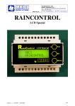
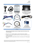
TD-DGE43NAVI-AAN
TD-DGE43NAVI-P1.2
TD-DGE84NAVI-AAN
TD-DGE84NAVI-P1.2
Dodge/Chrysler
Navigation Installation Manual
What’s In The Box
2
• NAV-TV UCI-11C Video Interface
• NAV-TV LVDS Cable
• NAV-TV T-Harness
• NAV-TV Camera Input Harness
•NAV-TV USB Cable
•IntraphexTM RGB / Data Cable
•Prodigy 1.2 or Mini Navigation Brain
• 8GB SD Card with IntraphexTM Navigation Software
•Install / Users Guides
•GPS Antenna
•Speaker
•Microphone
(Prodigy 1.2 Only)
•IntraphexTM Mouse
•Connector One (Prodigy 1.2 Only)
•Connector Two
(Prodigy 1.2 Only)
•WI-FI Dongle
(Prodigy 1.2 Only)
•4-Pin Power Harness (Prodigy Mini Only)
This manual explains the installation and wiring
of the Prodigy Mini and Prodigy 1.2 Systems.
During the process of your installation, please take
note to reference the correct wiring diagram that
corresponds with the system that you are installing.
Features such as the microphone and WI-FI dongle
are specific to the Prodigy 1.2 System.
3
GPS
RGB
V1
Speaker
P1.2
AAN
V3
Reverse Cam Input V2
Data
Navigation Harness
Factory
Radio
UCI-11C
Factory Radio Harness
From Car
Factory
Monitor
LVDS To Screen
Factory LVDS Harness From Car
PRODIGY MINI CONNECTIONS
RGB
4 PIN
SPEAKER
LED
GPS
CVBS VIDEO
USB
DATA
SD CARD SLOT
UART (NOT USED)
POWER
LED STATUS
GREEN
POWER ON
AMBER
BOOT SUCESSFUL
FLASHING GREEN/AMBER
4
GPS SIGNAL AQUIRED
PRODIGY 1.2 CONNECTORS
***NOTE*** MICROPHONE IS THE THINNER OF THE 3.5MM JACKS
5
Installation of UCI-11C Video Interface
1.Remove the factory dash of vehicle to gain access to the radio head. Pull the radio out enough to gain access to the wiring on the back. Unplug the factory white 22 pin connector from behind the radio. Install the male end of the supplied NAV-TV T-harness into the radio head. Plug the factory 22 pin connector into the female end of the supplied T-harness.
2. Route the free end of the T-harness behind the radio and up behind the factory screen.
3. When you removed the dash, there would have been a white round LVDS connector plugged into the back of the dash/monitor assembly. Take this connector and insert into the white UCI-11C port labeled “Radio.” Take the provided NAV-TV LVDS cable and insert the black end into the UCI-11C port labeled “screen.”
4.At this point you should find a suitable place to mount the UCI-11C.
5.Plug the free end of the supplied NAV-TV T-Harness (18 pin) into the UCI-11C port labeled “radio.”
6.Plug the supplied LVDS cable that you previously inserted into the black LVDS port on the UCI-11C labeled “screen,” and plug it into the vehicles factory LVDS port behind the monitor.
7. If you are using an aftermarket backup camera, plug in the 8 pin Molex plug with the RCA’s
into the UCI-11C. NOTE: ONLY VIDEO 2 WILL WORK AS A BACKUP CAMERA INPUT. The other
inputs are currently non-functional.
8. Locate the Intraphex RGB / Data harness. Plug the 24 pin end into the UCI-11C’s port labeled “Navigation.”
9. Run the RGB / Data cable to where you will be mounting the Prodigy brain.
Installation of the Prodigy 1.2 Brain
1.Find a suitable place to mount the navigation brain.
2.Plug in the 24 pin Connector 1 (Labeled “Con 1”) to the Prodigy 1.2 brain.
3.Connect the RGB and Data cables coming from the UCI-11C into the RGB and Data cables on
the Connector 1 harness. NOTE: These plugs do not have locking tabs. It’s suggested that you
heat shrink over the connection once made, or at least wrap tightly with electrical tape
4.Make all of your power connections. Red – ACC, Black – GND, Yellow – CONSTANT +12v. You will not use the White wire, simply insulate it to avoid any accidental contact. These power connections must be made at the cigarette lighter power wires. DO NOT make power connections behind the radio or tap into the NAV-TV T-harness. The UCI-11C is very sensitive to current draw and will shut down if you tap into a circuit it is using. On most applications, the
cigarette lighter wires are very easy to get to.
5.5. Run your antenna, speaker, and microphone. Please reference the connector diagram on
page 5.
6.Once all connections are made, start system and begin the setup process.
6
Installation of the Prodigy Mini Brain
1.Find a suitable place to mount the navigation brain.
2.Plug the RGB and Data cables coming from the UCI-11C into the RGB and Data plugs
located on the Prodigy Mini brain.
3.Locate the provided 4 pin IntraphexTM power harness and make all of your power
connections. Red – ACC, Black – GND, Yellow – CONSTANT +12v. You will not
use the White wire, simply insulate it to avoid any accidental contact. These power
connections must be made at the cigarette lighter power wires. DO NOT make power
connections behind the radio or tap into the NAV-TV T-harness. The UCI-11C is very
sensitive to current draw and will shut down if you tap into a circuit it is using. On
most applications, the cigarette lighter wires are very easy to get to.
4.Run your antenna and speaker wires to your desired locations.
5.Once all connections are made, start the system and begin the startup process.
Setup for 4.3” Screen Systems
1.Start vehicle and wait for systems to load completely.
2.To access the settings screen, press and hold the “Settings” hard key in the upper right
corner of the monitor assembly until the menu appears (usually about 3-5 seconds).
3.If you are adding an aftermarket camera,
first select “Camera Input Settings.” In this
menu, select “Video 2” (this is where you
should have connected your CVBS camera
input previously in the install. If the vehicle
came with a factory backup camera, select
“Head Unit,” and if you have no camera at
all, select “Off.” Once you have found your
desired setting click “Exit” to get back to
the main menu.
4.Enter the “Navigation Input Settings” menu. In this menu you will need to change the “Model”
setting to “WP.” Once you have made this selection, you can exit via the soft key.
5.From the main Settings menu you may also make adjustments to Brightness, Contrast, and Saturation as you would like.
6.Once you are done, use the soft exit key to get out of the UCI-11C menu.
7.Turn vehicle off, shut all doors, windows, hood, and trunk. Lock vehicle and wait 3 minutes for the vehicle’s CAN system to shut down. At this point all settings should have saved.
8.Make sure you test all functions before re-assembling vehicle.
7
Setup for the 8.4” Screen Systems
1.Start vehicle and wait for systems to load completely.
2.Press and hold the “Power” button
(located in the center of the volume
knob) for about 5 seconds.
3.If you are adding an aftermarket camera,
first select “Camera Input Settings.” In
this menu, select “Video 2” (this is where
you should have connected your CVBS
camera input previously in the install. If
the vehicle came with a factory backup
camera, select “Head Unit,” and if you
have no camera at all, select “Off.” Once
you have found your desired setting click
“Exit” to get back to the main menu.
4.Enter the “Navigation Input Settings”
menu. In this menu you will need to
change the “Model” setting to “WP.”
Once you have made this selection, you
can exit via the soft key.
5.In the same menu, you will also see a
selection for “Timing.” Leave it at its
default setting for the time being.
6. Once you are done, use the
soft exit key to get out of the
UCI-11C menu.
7. Turn vehicle off, shut all
doors, windows, hood, and
trunk. Lock vehicle and wait 3
minutes for the vehicle’s CAN
system to shut down. At this
point all settings should have
saved.
8. After the CAN system has
shut down, look at the factory
“soft buttons” at the bottom of
the screen. If they look like they
are cut off, go back into the
“Navigation Settings Menu” and change the timing to the other option (there are only two of
them). Exit via the soft exit key, and follow steps 6 and 7.
9.From the settings menu you may also make adjustments to Brightness, Contrast, Saturation
as you would like. Make sure all functions and display are correct before re-assembling
vehicle.
8
Calibrating the Screen
1.Start the vehicle and enter the RGB source. Prodigy 1.2: Press the soft “Navigation” key
in the bottom right and corner of the screen. Prodigy Mini: Press and hold the “Screen
Off” key until it switches to the Prodigy HMI.
2.NOTE: On this system, it is usually not necessary to calibrate the touch screen. Only
go through this process if the touch seems to be off. If using the Prodigy 1.2 insert the
included IntraphexTM mouse into the USB port on Connector Two (Con 2). Only one port
will work. You may need to remove the WIFI dongle to get the correct port. If using the
Prodigy Mini, try either port, one will work. Use the mouse to enter the “Settings” menu.
You will be prompted to enter a password. The password is “7777,” then press OK. Use
the mouse to click the calibration icon. You will see a white screen with a crosshair in the
center. Use your finger to press and release that point (Best results are from the driver’s
side of the vehicle). The crosshair will move to four (4) additional locations, then press
“Exit.” You may now remove the mouse. If using the P1.2 system, be sure to re-install the
WIFI dongle into the same port.
9
Installer Notes Finishing Up
10
1.To switch into and out of sources, use the “soft” button in the bottom lefthand corner of the screen.
2.Locate the envelope containing the navigation software SD card, and
insert it into the Prodigy brain. Install the plastic cover (two small Phillips
screws) on the brain to protect the SD card.
3.The navigation software will take you through a basic setup. It is defaulted
for the United States, so you can click “next” through the entire process.
The final stage of the initial setup may look for a network connection.
Click “Retry Later,” as this feature is no longer offered. All settings can be
changed in the “Settings” menu at a later time if need be.
4.Be sure to leave the Navigation Quick Start Guide/User’s Manual” in the
vehicle for the End User.
1.Be sure to test unit before re-assembling the vehicle. You don’t want to
have to go back and Disassemble/Reassemble the vehicle.
2.After you have finished the installation, keep the provided Intraphex
mouse. You may need to use it one day – it will make an excellent
addition to the “junk” drawer of your toolbox.
3.Only one USB port will work with the Intraphex mouse. If you try one port
and it doesn’t work, simply use the other. On the Prodigy 1.2 system,
there may be a white WIFI dongle installed into the port that works for the
mouse. In this case, simply remove the dongle and replace it after you
have finished your setup.
INTRAPHEX THREE YEAR LIMITED WARRANTY NONTRANSFERABLE
Terms of Limited Warranty INTRAPHEX warrants to the original retail purchaser, that the
product(s) purchased from an INTRAPHEX authorized dealer, in the original vehicle, are free
from defects in materials or workmanship under normal use and conditions for a period of
THREE (3) years from date of purchase. A sales receipt, showing the installation date and
INTRAPHEX product details are required to verify proof of purchase. Should the product(s) be
determined defective during the applicable warranty period, the defective product(s) will be
repaired or replaced with a reconditioned product(s), at INTRAPHEX’s sole option. To obtain
warranty service, the product(s) must be returned to an INTRAPHEX authorized installer along
with proof of warranty coverage.
Exclusions
- Elimination of externally generated static or noise
- Costs incurred for installation, removal or reinstallation of the product(s)
- Damage to any vehicle parts, accessories or vehicle electrical system.
- Cosmetic damage or damage due to negligence, misuse, abuse, failure to follow operating instructions, accidental spills or customer applied cleaners
- Damage or loss due to environmental causes such as floods, airborne fallout, chemicals, salt, hail, windstorms, lightning or extreme temperatures
- Damage or loss due to accidents, road hazards, fire, theft or vandalism.
- Damage due to improper installation or connection, improper connection to equipment of another manufacturer, modification of existing equipment
- Product(s) which have been opened or tampered with for any reason or which have been damaged due to alteration or service performed by anyone other than INTRAPHEX
EXCEPT AS EXPRESSLY SET FORTH IN THIS LIMITED WARRANTY, INTRAPHEX MAKES NO
OTHER WARRANTIES, EXPRESSED OR IMPLIED, INCLUDING ANY IMPLIED WARRANTIES OF
MERCHANTABILITY AND FITNESS FOR A PARTICULAR PURPOSE. INTRAPHEX EXPRESSLY
DISCLAIMS ALL WARRANTIES NOT STATED IN THIS LIMITED WARRANTY. ANY IMPLIED
WARRANTIES THAT MAY BE IMPOSED BY LAW ARE LIMITED TO THE TERMS OF THIS
EXPRESSED LIMITED WARRANTY.
Some states do not allow limitation on how long an implied warranty lasts. In such states, the
limitations or exclusions of this Limited Warranty may not apply. Some states do not allow the
exclusion or limitation of incidental or consequential damages. In such states, the exclusion
or limitation of this Limited Warranty may not apply to you. This Limited Warranty gives you
specific legal rights and you may have other rights, which vary from state to state.
11
Toll Free Tech Support: 888-228-5560
Local: 727-803-0324
Email: [email protected]