1
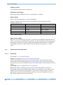
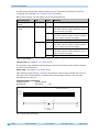
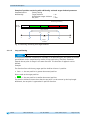
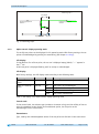
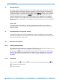
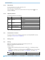
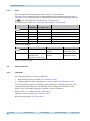
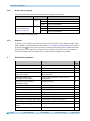
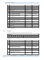
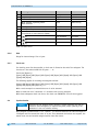
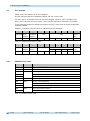
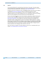
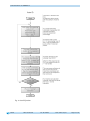
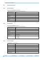
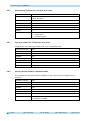
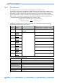
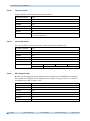
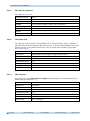
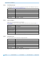
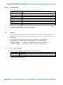
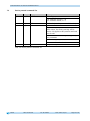
Display and control keys 2.1 Switching on the supply voltage The AP10 will be initialized after switching on the supply voltage. A display test is executed during initialization, the LEDs are lighted consecutively and the configutation parameters are loaded from the non-volative memory into the RAM of the controller. With the display still unconfigured all parameters are set to their default values. See to it that the bus will be connected only after correct adjustment of baud rate and ID (see chapter 4.3: Parameterization of the position indicator and 6.8: Auto-ID). The AP10 functions with the data last parameterized. AP10 is in the normal operating state. According to the requirements of the application, the display can be parameterized via the SIKONETZ5 interface in this state. 3 Display and control keys 3.1 General The position indicator has a two-line display with special characters and three control keys. The keys serve for position indicator parameterization and control. Two LEDs (1) serve for monitoring positioning. LED1 Fig. 1: Control elements 3.2 LCD display The The display range is limited to -19999 … 99999. Values outside this range are displayed with "". With supply voltage applied to the position indicator with factory settings, the actual value will be displayed in the 1st row and the set point in the 2nd row. If there is no valid set point, "---" will be displayed in the 2nd row. The values displayed are determined by the operating mode. Direction indicators (arrows) support positioning. The battery symbol is shown with a critical or insufficient battery status. With incremental measurement function activated, the incremental measurement symbol is shown. AP10 Date: 03.09.2015 Art. No. 86855 Mod. status 319/15 Page 6 of 46