1
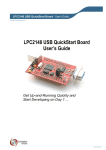
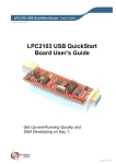
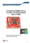
LPC2106 RS232 QuickStart Board - User’s Guide Copyright 2012 © Embedded Artists AB LPC2106 RS232 QuickStart Board User’s Guide Get Up-and-Running Quickly and Start Developing on Day 1… EA2-USG-0501 v1.1 Rev E LPC2106 RS232 QuickStart Board - User’s Guide Page 2 Embedded Artists AB Davidshallsgatan 16 SE-211 45 Malmö Sweden [email protected] http://www.EmbeddedArtists.com Copyright 2005-2012 © Embedded Artists AB. All rights reserved. No part of this publication may be reproduced, transmitted, transcribed, stored in a retrieval system, or translated into any language or computer language, in any form or by any means, electronic, mechanical, magnetic, optical, chemical, manual or otherwise, without the prior written permission of Embedded Artists AB. Disclaimer Embedded Artists AB makes no representation or warranties with respect to the contents hereof and specifically disclaim any implied warranties or merchantability or fitness for any particular purpose. Information in this publication is subject to change without notice and does not represent a commitment on the part of Embedded Artists AB. Feedback We appreciate any feedback you may have for improvements on this document. Please send your comments to [email protected]. Trademarks All brand and product names mentioned herein are trademarks, services marks, registered trademarks, or registered service marks of their respective owners and should be treated as such. Copyright 2012 © Embedded Artists AB LPC2106 RS232 QuickStart Board - User’s Guide Page 3 Table of Contents 1 Document Revision History 4 2 Introduction 5 2.1 Contents 5 2.2 Features 5 2.3 ESD Precaution 6 2.4 CE Assessment 6 2.5 Other Products from Embedded Artists 6 2.5.1 Design and Production Services 6 2.5.2 OEM / Education / QuickStart Boards and Kits 7 3 Board Design 8 3.1 Board Schematics 8 3.2 Mechanical Dimensions 11 3.3 Examples 11 3.3.1 JTAG 11 3.3.2 Reset 13 3.3.3 I2C 13 3.3.4 SPI 14 3.3.5 LEDs 14 4 Getting Started 4.1 Test program 16 4.2 Program Development 16 5 Further Information Copyright 2012 © Embedded Artists AB 16 17 LPC2106 RS232 QuickStart Board - User’s Guide Page 4 1 Document Revision History Revision Date Description v1.1 rev E 2012-01-13 Added this revision history table. Added note about ESD precaution and CE marking. Removed schematic from document. Copyright 2012 © Embedded Artists AB LPC2106 RS232 QuickStart Board - User’s Guide Page 5 2 Introduction Thank you for buying Embedded Artists’ LPC2106 RS232 QuickStart Board based on NXP’s ARM7TDMI LPC2106 microcontroller. This document is a User’s Guide that describes the LPC2106 RS232 QuickStart Board design along with the accompanying software and program development tools. The document contains information on how to use and integrate the board in your own designs, including electrical and mechanical information. 2.1 Contents The box received when ordering the LPC2106 RS232 QuickStart Board contains the following: The LPC2106 RS232 QuickStart Board. In addition, the following is needed in order to start developing applications with the LPC2106 RS232 QuickStart Board: A DC power supply, 4-6 volt, capable of providing at least 150 mA (more if external circuits need power from the 3.3 volt supply). Note that the LPC2106 RS232 QuickStart Board does not contain any reverse polarity protection. If voltage is applied with wrong polarity, the board will likely be damaged. Also note that 6.0 volt is the absolute maximum voltage that can be applied without damaging the on-board voltage regulator (TPS70251). Consult the TPS70251 datasheet for exact details. A serial extension cable, DB9-male to DB9-female (DB9M-DM9F), for connecting the LPC2106 RS232 QuickStart Board to a PC. An optional JTAG interface, for program development debugging. 2.2 Features Embedded Artists’ LPC2106 RS232 QuickStart Board lets you get up-and-running quickly with NXP’s ARM7TDMI LPC2106 microcontroller. The small form factor board offers many unique features that ease your development. NXP’s ARM7TDMI LPC2106 microcontroller with 128 Kbyte program Flash and 64 Kbyte SRAM All LPC2106 I/O pins are available on connectors 14.7456 MHz crystal for maximum execution speed and standard serial bit rates Phase-locked loop (PLL) multiplies frequency with four; 4 x 14.7456 MHz = 58.9825 MHz ESD/EMI protected RS232 channel with DSUB-9 connector 256 Kbit I2C E2PROM Onboard low-dropout voltage and reset generation. Generates +3.3V and +1.8V from a single +5V supply +3.3V available for external circuits, up to 300 mA Power supply: 4-6 VDC, at least 150 mA Simple and automatic program download (ISP) via RS232 channel Copyright 2012 © Embedded Artists AB Circuit that automatically controls the boot loader from RS232 channel Easy to connect to JTAG signals LPC2106 RS232 QuickStart Board - User’s Guide 2.3 Page 6 Dimensions: 27.9 x 65.3 mm DIL form factor with 2x20 pins (21.6 mm, 0.85” between pin rows) Four layer PCB (FR-4 material) for best noise immunity ESD Precaution Please note that the LPC2106 RS232 QuickStart Board come without any case/box and all components are exposed for finger touches – and therefore extra attention must be paid to ESD (electrostatic discharge) precaution. Make it a habit always to first touch the ground pin on the expansion pin list for a few seconds with both hands before touching any other parts of the board. That way, you will have the same potential as the board and therefore minimize the risk for ESD. Note that Embedded Artists does not replace boards that have been damaged by ESD. 2.4 CE Assessment The LPC2106 RS232 QuickStart Board is CE marked. See separate CE Declaration of Conformity document. The LPC2106 RS232 QuickStart Board is a class B product. EMC emission test has been performed on the LPC2106 RS232 QuickStart Board. General expansion connectors where internal signals are made available have been left unconnected. Connecting other devices to the product via the general expansion connectors may alter EMC emission. It is the user’s responsibility to make sure EMC emission limits are not exceeded when connecting other devices to the general expansion connectors of the LPC2106 RS232 QuickStart Board. Due to the nature of the LPC2106 RS232 QuickStart Board – an evaluation board not for integration into an end-product – fast transient immunity tests and conducted radio-frequency immunity tests have not been executed. Externally connected cables are assumed to be less than 3 meters. The general expansion connectors where internal signals are made available do not have any other ESD protection than from the chip themselves. Observe ESD precaution. Note that the LPC2106 RS232 QuickStart Board can also be considered to be a component if integrated into another product. The CE mark on the LPC2106 RS232 QuickStart Board cannot be extended to include the new (user created) product. It is the user’s responsibility to make sure EMC emission limits are not exceeded and CE mark the final product. 2.5 Other Products from Embedded Artists Embedded Artists have a broad range of LPC1000/2000/3000/4000 based boards that are very low cost and developed for prototyping / development as well as for OEM applications. Modifications for OEM applications can be done easily, even for modest production volumes. Contact Embedded Artists for further information about design and production services. 2.5.1 Design and Production Services Embedded Artists provide design services for custom designs, either completely new or modification to existing boards. Specific peripherals and I/O can be added easily to different designs, for example, communication interfaces, specific analog or digital I/O, and power supplies. Embedded Artists has a broad, and long, experience in designing industrial electronics in general and with NXP’s LPC1000/2000/3000/4000 microcontroller families in specific. Our competence also includes wireless and wired communication for embedded systems. For example IEEE802.11b/g (WLAN), Bluetooth™, ZigBee™, ISM RF, Ethernet, CAN, RS485, and Fieldbuses. Copyright 2012 © Embedded Artists AB LPC2106 RS232 QuickStart Board - User’s Guide 2.5.2 Page 7 OEM / Education / QuickStart Boards and Kits Visit Embedded Artists’ home page, www.EmbeddedArtists.com, for information about other OEM / Education / QuickStart boards / kits or contact your local distributor. Copyright 2012 © Embedded Artists AB LPC2106 RS232 QuickStart Board - User’s Guide Page 8 3 Board Design This chapter contains detailed information about the electrical and mechanical design of the LPC2106 RS232 QuickStart Board. The schematic can be downloaded in pdf format from the support page, and is recommended to have printed out while reading this chapter. A number of example circuits are also presented that will lower the threshold of start developing with the board. 3.1 Board Schematics Note that version 1.2 of the design has updated the power supplies and the rest generation, but both versions are compatible. Besides the LPC2106 microcontroller from NXP, the board contains a dual voltage regulator with an internal reset generator, a 256 Kbit I2C E2PROM, and an ESD/EMI protected RS232 serial channel. A red LED is connected to the reset signal and lights when reset is active, i.e., the signal is low. The microcontroller crystal frequency is 14.7456 MHz. This frequency has been selected in order to allow close to maximum execution speed (4 x 14.7456 MHz = 58.9824 MHz, which is very close to the maximum frequency, 60 MHz) as well as to provide standard serial communication bit rates. The crystal frequency can be changed to any desired value for OEM orders, provided that the conditions in the LPC2106 datasheet are met. Current requirements are (but consult the most current datasheet for latest details): 1-30 MHz if the on-chip phase-locked loop (PLL) is not used, or 10-25 MHz if the PLL is to be used. The design has direct and automatic support for program downloading (via ISP) over the RS232 serial channel. The RS232 signal DTR controls the reset signal to the LPC2106 microcontroller. The RS232 signal RTS is connected to pin P0.14 in the LPC2106 microcontroller. This pin is sampled after reset and determines if the internal bootloader program shall be started, or not. A low signal after reset enters the bootloader mode. Both the RS232 receive and transmit signals as well as the RTS/DTR signals can be disconnected from the microcontroller via four links / jumpers on the board. See Figure 1 below for details. Copyright 2012 © Embedded Artists AB LPC2106 RS232 QuickStart Board - User’s Guide Page 9 In order from left to right: J4 (TxD), J5 (RxD), J6 (P0.14), J7 (Reset) Figure 1 - LPC2106 RS232 QuickStart Board Jumpers It is possible to use the RS232 signals RTS and CTS, which are available to the microcontroller signals P0.22 and P0.23 via the zero ohm resistors R2 and R3. Note that R2 and R3 are not mounted on the board and that such control must be implemented in software. There is no hardware control of these signals. The board interface connectors are placed in two 20 pin rows along the board edges. They are 850 mil (0.85 inch, 21.6 mm) apart and can be viewed as a DIL-40 package. However, note that a standard DIL-40 package has the rows 600 mil (0.6 inch) apart, and not 850 mil (0.85 inch, 21.6 mm) like the LPC2106 RS232 QuickStart Board has. Figure 2 below illustrates how the two row connectors can be viewed as a DIL package. Copyright 2012 © Embedded Artists AB LPC2106 RS232 QuickStart Board - User’s Guide Figure 2 - LPC2106 RS232 QuickStart Board Interface Connectors Viewed as a DIL Package Copyright 2012 © Embedded Artists AB Page 10 LPC2106 RS232 QuickStart Board - User’s Guide 3.2 Page 11 Mechanical Dimensions Figure 3 below contains a drawing of the board that includes mechanical measures. about 12 mm P0.0 P0.31 65.3 mm, 2570 mil P0.15 P0.16 21.6 mm, 850 mil 27.9 mm, 1100 mil Figure 3 - LPC2106 RS232 QuickStart Board Mechanical Dimensions 3.3 Examples This section contains a few sample / illustrative circuit examples that will help you to quickly get upand-running with the board interface design. Detailed information about the on-chip peripheral units can be found in the LPC2106 User’s Manual. 3.3.1 JTAG The LPC2106 microcontroller contains a JTAG interface that can be used for debug purposes during program development. The circuit in Figure 4 below works for many JTAG interfaces on the market, including J-link from Segger, Ulink from Keil, and Wiggler from MacRaigor. The signal DBGSEL on the LPC2106 microcontroller is sampled during reset. Jumper J10 drives the signal high. If the signal is found high, the JTAG interface is enabled. Pin P0.17-P0.21 then changes from being general I/O pins to dedicated JTAG pins. Copyright 2012 © Embedded Artists AB LPC2106 RS232 QuickStart Board - User’s Guide Page 12 Some JTAG interfaces require the signal RTCK to be held low (jumper J11) and some that the JTAG signals TRST and RST are connected (optional 0 ohm resistor). Consult your JTAG manual for specific information. Note that many Wiggler JTAG interfaces do not work with a processor crystal frequency above about 10 MHz. If this is the case, the crystal frequency can be changed by desoldering the 14.7456 MHz crystal and replace it with another suitable one. Figure 4 – Example JTAG Interface Copyright 2012 © Embedded Artists AB LPC2106 RS232 QuickStart Board - User’s Guide 3.3.2 Page 13 Reset The on-board voltage regulator also contains a reset generator. The reset signal will be held active (i.e., low) until both internal voltages (i.e., +3.3V and +1.8V) are within margins. The reset duration is about 120 mS (consult the TPS70251 datasheet for exact details). The output reset signal is an opencollector / open-drain output. An external reset source can also control the reset generator. Version 1.2 of the board has an updated reset generator based on CAT811S (consult the CAT802S datasheet for details). Figure 5 below illustrate how an external push-button can generate a reset. Note that an external driver must be an open-collector / open-drain driver. Figure 5 – Example External Reset Push-button 3.3.3 I2 C The LPC2106 microcontroller has an on-chip I2C communication channel. The LPC2106 RS232 QuickStart Board has connected a 256 Kbit E2PROM to this bus. More peripheral units are easily connected to the two-wire I2C bus. Figure 6 below illustrates how a pin expander circuit (PCF8574) can be connected to the I2C bus. Copyright 2012 © Embedded Artists AB LPC2106 RS232 QuickStart Board - User’s Guide Page 14 Figure 6 – Example I2C Interface Note that the pull-up resistors (which are always needed on I2C busses) are included on the LPC2106 RS232 QuickStart Board., and are hence not needed on the external circuit. The pull-up resistors are 3000 ohm each (see Fel! Hittar inte referenskälla. for complete board schematics). 3.3.4 SPI The LPC2106 microcontroller has an on-chip SPI serial communication channel. Figure 7 below illustrates how serial E2PROM chip is connected to the LPC2106 RS232 QuickStart Board. Note that signal SSEL (i.e., P0.7) must be high when the SPI controller (in LPC2106) operates as a master, and master operation is the normal operating mode. In Figure 7 below, signal P0.25 is used as an example to control the chip select to the serial E2PROM chip. Any other pin can be used to control chip select signals. Note that one chip select signal is requires for each external chip that is connected to the SPI bus. Figure 7 – Example SPI Interface 3.3.5 LEDs The port pins of the LPC2106 microcontrollers have a 4 mA driving capacity, just enough to directly drive LEDs. Figure 8 below illustrates how current is sunk into the microcontroller to drive the LEDs. Current sourcing is possible just as well. The resistors limit the current to about 4 mA. The preloaded test program (described in Section 4.1 ) outputs a running-zero on the port pins (P0.4 – P0.31), in Copyright 2012 © Embedded Artists AB LPC2106 RS232 QuickStart Board - User’s Guide Page 15 order to create a running-one pattern on the LEDs. A circuit like the one in Figure 8 below can be used to verify correct operation. Figure 8 – Example LED Driving Copyright 2012 © Embedded Artists AB LPC2106 RS232 QuickStart Board - User’s Guide Page 16 4 Getting Started 4.1 Test program The LPC2106 RS232 QuickStart Board comes preloaded with a test program. This program can be used to verify that the board operates correctly. A circuit, like the one found in Figure 8, can be used to attach LEDs to port pins P0.4 – P0.31. Pins P0.0 – P0.1 are tested via the serial channel and pins P0.2 – P0.3 are tested via the I2C bus. The test program outputs a running-zero to port pins P0.4 – P0.31, meaning that one LED at a time will light (in a running-one pattern). Also, a terminal program should be attached to the RS232 DSUB-9 connector. The test program will output test information regarding the I2C and E2PROM test. Also, the UART/RS232 channel can be tested by typing characters in the terminal program. The settings for the terminal program are: 115.2 kbps, 8 data bits, no parity bits, and one stop bit (i.e., 8N1). The output from the test program will look something like in Figure 9 below. Figure 9 – Example Test Program Output 4.2 Program Development Consult the QuickStart Program Development User’s Manual for more information about the QuickStart Build Environment from Embedded Artists, and program development for the ARM7 in general. Copyright 2012 © Embedded Artists AB LPC2106 RS232 QuickStart Board - User’s Guide Page 17 5 Further Information The LPC2106 microcontroller is a complex circuit and there exist a number of other documents with a lot more information. The following documents are recommended as a complement to this document. [1] NXP LPC2106 Datasheet http://ics.nxp.com/products/lpc2000/pdf/lpc2104.lpc2105.lpc2106.pdf [2] NXP LPC2106 User’s Manual http://ics.nxp.com/support/documents/microcontrollers/pdf/ user.manual.lpc2104.lpc2105.lpc2106.pdf [3] NXP LPC2106 Errata Sheet http://ics.nxp.com/support/documents/microcontrollers/pdf/errata.lpc2106.pdf [4] ARM7TDMI Technical Reference Manual. Document identity: DDI0029G http://www.arm.com/pdfs/DDI0029G_7TDMI_R3_trm.pdf [5] ARM Architecture Reference Manual. Document identity: DDI0100E Book, Second Edition, edited by David Seal, Addison-Wesley: ISBN 0-201-73719-1 Also available in PDF form on the ARM Technical Publications CD [6] ARM System Developer’s Guide – Designing and Optimizing System Software, by A.N. Sloss, D Symes, C. Wright. Elsevier: ISBN 1-55860-874-5 [7] Embedded System Design on a Shoestring, by Lewin Edwards. Newnes: ISBN 0750676094. [8] GNU Manuals http://www.gnu.org/manual/ [9] GNU ARM tool chain for Cygwin http://www.gnuarm.com [10] An Introduction to the GNU Compiler and Linker, by Bill Gatliff http://www.billgatliff.com [11] LPC2000 Yahoo Group. A discussion forum dedicated entirely to the NXP LPC2xxx series of microcontrollers. http://groups.yahoo.com/group/lpc2000/ [12] The Insider’s Guide to the NXP’s ARM7-Based Microcontrollers, by Trevor Martin. http://www.hitex.co.uk/arm/lpc2000book/index.html Also note that there can be newer versions of the documents than the ones linked to here. Always check for the latest information / version. Copyright 2012 © Embedded Artists AB