1
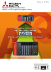
2005
2006
Mar
Dec
Open Field Network
CC-Link, CC-Link/LT Compatible Product Development Guidebook
From consulting to the provision of dedicated communication LSIs,
Mitsubishi Electric is ready to assist you in speedy development of
CC-Link & CC-Link/LT compatible products.
Development Procedure Flowchart ÉÉ P03 to P04
Development Method Selection Flowchart É P05 to P06
Station Development Guides
[ CC-Link ]
Master Stations, Local Stations
and Intelligent Device Stations
Remote Device Stations
Remote I/O Stations
Drivers
P07 to P10
É P11 to P12
ÉÉÉÉ P13 to P16
ÉÉÉÉÉÉÉÉÉÉÉ P17 to P18
(for Q80BD-J61BT11N)
[ CC-Link/LT ]
Master Stations
ÉÉÉÉÉ P19 to P20
Remote Device Stations
Remote I/O Stations
É P21 to P22
ÉÉ P23 to P24
Making your products compatible with CC-Link & CC-Link/LT,
Specified Parts ÉÉÉÉÉÉ P25 to P26
an open field network originating from Japan,
Technical Information ÉÉ P27 to P31
will not only ensure the level of system flexibility distinctively characteristic
Support System
of multi-vendor products but also provide you with the opportunity
Related Product List ÉÉÉ P33
to boost the competitiveness of your products to the global level once and for all.
Warranty
With SEMI certification*1, Chinese national standard GB*2 certification,
international standard ISO 15745*3 certification, and now international standard
IEC 61158*4 certification, CC-Link and CC-Link/LT have entered the spotlight.
To ensure quick and certain development
of CC-Link and CC-Link/LT compatible products,
Mitsubishi Electric will support you in every phase of development,
including the provision of dedicated communication LSIs.
Mitsubishi Customer CLPA
Electric
*1. SEMI E54, 12
*2. GB/Z ... "Control and Communication Field Network CC-Link Standard"
*3. "Application Integration Framework"
*4. Industrial network
ÉÉÉÉÉ P32
ÉÉÉÉÉÉÉÉÉÉ P34
Recommended path to CC-Link & CC-Link/L
CC-Link/LTT compatible product development
Mitsubishi Electric
Purchasing Reference Manuals
Inquiries & Consulting
Purchasing Dedicated Communication LSIs
Mitsubishi Electric will provide product development
Our Open System Center will answer
consultation free of charge. Our Open System
Center welcomes the opportunity to discuss with
you the various development methods available
To purchase reference manuals, contact
and the related requirements.
a Mitsubishi representative office or dis-
[ Contact ]
Technical Support
tributor of the device or product.
Please contact one of the CC-Link Partner Association sites indicated on P. 32.
To purchase products such as a dedi-
by phone or e-mail any technical ques-
cated communication LSI or built-in in-
tions that you may have during the de-
terface board specifically required for
velopment process, free of charge. In
the development method, contact a
North America, you may contact the
Mitsubishi representative office or dis-
CLPA-N.America office.
tributor of the device or product.
The site will contact the Mitsubishi Electric
Nagoya Works Open System Center.
(
This free support requires
the purchase of a reference manual.
(
Development
method selection
Customer
Development study
Assessment and
sales preparation
Design and development
Product
shipment
Purchasing of
specified parts
Joining the CC-Link Partnership Association
Obtaining Conformance Test Specifications
Executing the Conformance Test
CLPA
In order to develop and sell CC-Link compat-
The CC-Link and CC-Link/LT compatible
ible products, you will need to join the CCLink Partner Association as a regular mem-
For conformance testing of the devel-
ber, executive member or board member.
oped product, the CC-Link Partner
[ Contact ]
Association provides ÒConformance
Please contact one of the CC-Link Partner
Association sites indicated on P. 32.
Promotion Support
Test SpecificationsÓ free of charge.
products you have developed will be lisThe CLPA will conduct a conformance
test (fee applied) based on the
ÒConformance Test Specifications.Ó
ted in CLPA catalogs and on our Web
site, expanding your opportunities for
sales. As a partner manufacturer, you
will also be invited to participate in
events held by CLPA.
The strongest theme in CC-Link and CC-Link/LT compatible product development is the simultaneous pursuit of quality and development speed. This includes the
development of dedicated communication LSIs, which requires from the initial stages extreme efficiency with respect to both cost and speed. Mitsubishi Electric
prepares each type of dedicated communication LSI and built-in module through our comprehensive CC-Link & CC-Link/LT related technologies cultivated to date,
and is pleased to offer its support in the development of efficient compatible products. Capable of highly detailed assistance, from consulting during the preparation stage to problem solving during development, Mitsubishi Electric and the CC-Link Partner Association (CLPA) are eager to serve you as your partners.
3
4
P7 to P10
Built-in interface board <Q50BD-CCV2>
In this method, stations are developed using a built-in interface board. The CC-
Purchase
reference manual
Link master station, local station and intelligent device station functions are
Purchase
specified parts
Conformance
test
Purchase
specified parts
Conformance
test
realized by mounting the interface board on a user circuit board.
Object development <SW1D5C-CCV2OBJ-E>*1
Master station
In this method, stations are developed using objects. With object based
Contract
Purchase
reference manual
Purchase
dedicated LSI
development, use of a built-in interface board results in a design with higher
flexibility.
What type of product
Local station
will be developed?
Intelligent device station
P11 to P12
Dedicated communication LSI <MFP3N>
MFP3N is a communication LSI that allows you to develop devices that handle bit data
Remote device station
and word data without concern about protocol. The MPU is mounted and controlled by
Purchase
reference manual
Purchase
dedicated LSI
Purchase
specified parts
Conformance
test
software. Support of both CC-Link Ver. 1 and Ver. 2 is possible by changing the software.
P13 to P16
Slave station
Dedicated communication LSI <MFP2N/MFP2AN>
MFP2N and MFP2AN are communication LSIs that allow you to develop devices that handle bit data without concern
Remote I/O station
about protocol. The two types are provided for different package sizes (number of pins) and I/O point quantity.
Purchase
reference manual
Purchase
dedicated LSI
Purchase
specified parts
Conformance
test
Embedded I/O Adapter*2*3
This small-sized Embedded adapter allows you to develop devices that handle bit data without concern about
Development of
What is
compatible product
the network type?
protocol. The module can be mounted directly on the circuit board you developed, and allows expansion of the
Purchase
reference manual
Conformance
test
number of I/O points through cascade connection. (A maximum of two modules can be mounted on a single circuit
P17 to P18
PC interface board
Driver reference manual *2
driver
Drivers for various operating systems can be developed for use of the Mitsubishi
PC interface board (Q80BD-J61BT11N).
Purchase
reference manual
P19 to P20
Master station
Dedicated communication LSI <CLC13>
*4
CLC13 is a communication LSI that allows you to develop devices compliant with the master station used
for network management. The network can be constructed by connecting the various slave stations.
What type of product
will be developed?
Purchase
reference manual
Purchase
dedicated LSI
Purchase
recommended Parts
Remote device station
Conformance
test
P21 to P22
Dedicated communication LSI <CLC31>*4
Slave station
CLC31 is a communication LSI that allows you to readily handle CC-Link/LT word data (16-bit data). The data amount of
Purchase
reference manual
Purchase
dedicated LSI
Purchase
recommended Parts
Conformance
test
Purchase
reference manual
Purchase
dedicated LSI
Purchase
recommended Parts
Conformance
test
four words can be handled by a single LSI, allowing easy development of analog I/O and other remote device stations.
Remote I/O station
Dedicated communication LSI <CLC21>*4
CLC21 is a communication LSI that allows you to develop devices that handle bit data without concern
about protocol. This LSI enables easy development of digital I/O and other remote I/O stations.
*1. The reference manual is included with SW1D5C-CCV20BJ.
*2. CC-Link Partner Association membership is not always necessary. For details, contact your local CLPA office.
5
*3. The conformance test is sometimes not required. For details, contact your local CLPA office.
*4. The specified parts to be purchased include recommended parts.
6
CC-Link Ver.2 Built-in Interface Board
Q50BD-CCV2
Interface Board and User Circuit Board Block Diagram
User Circuit Board
Q50BD-CCV2 Interface Board
MPU
MPU
1. The CC-Link Ver.2 built-in interface board enables easy
(SH3)
Q50BD-CCV2
development of master stations, standby master stations,
CC-Link master station, standby master station, local station and intelligent device station functions can be realized
ROM
(driver)
by mounting the interface board onto the user circuit board.
2. This product is compatible with CC-Link Ver.2.
CC-Link interface
With CC-Link Ver.2 compatibility, the number of cyclic
*1
Connector
data points can be extended to 8,192 points for RX/RY
Address bus
Data bus
Dual port
control signals
Dual port
control signals
Transmission gate
RS485
and 2,048 words for RWr/RWw. The board is also com-
5V
5V
converter
Photocoupler
*1. The CC-Link interface
(
Address bus
MFP1N
Data bus
RAM
Flash
ROM
Dual port
Dual port
RAM
control signals
32K words
Dual port
control signals
Transmission gate
signals
transceiver
DC/DC
patible with old specifications (Ver.1).
General-purpose bus connector
General-purpose bus connector
local stations and intelligent device stations.
signals
SD
SD
RD
RD
5V
area) is required.
3. Minimal space is required.
SG
The interface board is designed with a compact size of
SG : Signal Ground
70mm x 80mm.
4. Communication with user circuit board circuitry can be
Q50BD-CCV2
easily performed using a general-purpose bus interface.
Circuit Board Dimensions
3-¿2.8 hole with through hole land (SG)
70±0.15
Unit : mm
C
1
The interface between the user circuit board and inter-
5
face board is comprised of general memory control sigC
1
nals (address bus, data bus, read, write, etc.), making
communication with the user circuit board easy.
Bus interface
General-purpose bus interface
MPU
SH3 (SH7708R) QFP 144 pins
ROM
ROM 512K words x 16 bits (8Mbits)
Dual port RAM 32K words x 16 bits (512Kbits)
Internal memory
2
2
1
C
1.27
7
3-¿2.8 hole
36.83±0.2
SG : Signal Ground
20.32±0.2
Q50BD-CCV2
Bus, MPU
2
Item
C
11.43
15.51±0.2
Description
Classification
1
Built-in interface board basic specifications
C
6.35
7.5
45
16
1
30.48±0.2
Interface board and user circuit board configuration example
28.26
¥Lead-free/RoHS directive compliant
1.5
User circuit board
ners are introduced.
SQT-128-01-L-T
37±0.2
request, hardware and software development part80±0.15
¥Upon
This drawing is a C-side view of the circuit board.
Manual
Q50BD-CCV2 Reference Manual
Title
Manual No.
CC-Link Ver.2 Built-in Interface Board Reference Manual
SH(NA)-080324ENG
Contact
SRAM
Work RAM 256K words x 16 bits (4Mbits)
Communication area
7
Communication chip
Mitsubishi Electric
Corporation
MFP1N
Display
Six LEDs: Green (RUN, L RUN, SD, RD) Red (ERR., L ERR.)
Switch
Station number switch, transmission speed, mode switch, select switch
Current consumption
0.32A
Circuit board dimensions
70.0 x 80.0mm
Weight
0.03kg
*Provides circuit examples, timing charts, pin assignments and driver development methods.
CC-Link Ver.2 Built-in Interface Board Q50BD-CCV2
Name
Model
CC-Link Ver.2 Built-in Interface Board
Q50BD-CCV2
Contact
Mitsubishi Electric
Corporation
8
Mounting Example with Object Development
CC-Link Ver.2 Object Development
[4] MPU (SH3)
[1] MFP1N
1. The CC-Link Ver.2 compatible product development tool with
SW1D5C-CCV2OBJ-E
object software allows you to develop master stations, local sta-
[2] CPLD
tions, intelligent device stations and standby master stations.
2. This product is compatible with CC-Link Ver.2.
[6] MPU (any)
With CC-Link Ver.2, the maximum number of cyclic data
[3] Flash ROM
points can be extended to 8,192 points for RX/RY and
2,048 words for RWr/RWw. CC-Link Ver.2 is also compatible with old specifications (Ver.1.10).
[7] ROM (driver)
3. Data communication can be easily performed.
(Developed by user)
Use of a dual port RAM enables easy data communication
between the network circuit and user application circuit.
4. The object code installation method is selectable.
[5] SW1D5C-CCV2OBJ-E
To develop CC-Link Ver.2 compatible products, object code
installation is required. An installation method can be selec-
Device kit
¥ Serial communication
Communication LSI
ted from two methods: using serial communication and us-
[8] Communication interface
¥ ROM writer
(MFP1N)
(Specified part)
ing a ROM writer. As a transfer tool for the serial communication,
use
the
ÒHyper
TerminalÓ
function
provided
in
Name
Windows¨2000/Windows¨XP.
[1]
5. The CC-Link Ver.2 compatible product development tool
Product Name
Manufacturer
A6GA-CCMFP1NN**F
Mitsubishi Electric
Master, Local, Intelligent Device Station LSI
Corporation
MFP1N (PC96002M-C)
with object software is composed of the object code
(SW1D5C-CCV2OBJ-E) and a network circuit. The network
circuit is made up using a device kit (Q6KT-NPC2OG51).
¥Upon
request, hardware and software development part-
[2]
CPLD
Q6KT-NPC2OG51 (Device Kit)
Mitsubishi Electric
[3]
Flash ROM
(Flash ROM x 1, CPLD x 2) x 40
Corporation
[4]
MPU (CC-Link compatible product
Renesas Technology
SH3 (SH7708R)
development tool with object software area)
ners are introduced.
¥Lead-free/RoHS directive compliant
Manual
SW1D5C-CCV2OBJ-E
Object (firmware binary file)
Mitsubishi Electric Corporation
[6]
MPU
Any MPU can be used.
Any manufacturer
[7]
Driver
SW1D5C-CCV20BJ-E Reference Manual
Title
Manual No.
CC-Link Ver.2 Compatible Product Development Tool with Object Software
(Master Station, Local Station and Intelligent Device Station) Reference Manual
SH(NA)-080552ENG
Contact
Mitsubishi Electric
Corporation
[5]
Firmware used to communicate with the CC-Link compatible
Developed by user
product development tool with object software area.
[8]
Communication interface
Use the specified part.
Each manufacturer
Corporation
*Provides circuit examples, timing charts and driver development methods.
Dedicated Communication LSI (MFP1N), Device Kit
CC-Link Ver.2 Compatible Product Development Tool with Object Software Basic Specifications
[1] Dedicated Communication LSI (MFP1N)
Description
Name
Model
MFP1N (PC96002M-C)
A6GA-CCMFP1NN60F
A6GA-CCMFP1NN300F
Packaging Unit
Contact
60 pieces
Mitsubishi Electric
300 pieces
Corporation
Classification
MPU
*Package: 100-pins, QFP size: 20 x 14mm, Pin spacing: 0.65mm
[2] Device Kit
Item
MPU
SH3 (SH7708R) QFP 144 pins
ROM
ROM
512K words x 16 bits (8M bits)
Dual port RAM
32K words x 16 bits (512K bits)
Work RAM
256K words x 16 bits (4M bits)
Internal memory
Name
Model
Q6KT-NPC2OG51
Device kit
(Flash ROM x 1, CPLD x 2) x 40
Packaging Unit
40 sets
SRAM
Contact
Mitsubishi Electric
Corporation
Network Circuit
Communication area
Communication chip
MFP1N
Nine LEDs : Green*1 (RUN, L RUN, SD, RD, BOOT, BOOT OK)
Display
Object Code
Title
CC-Link Ver. 2 Compatible Product Development
Tool with Object Software CD-ROM
9
Model
SW1D5C-CCV2OBJ-E
Contact
Mitsubishi Electric
Switch
Red*1 (ERR., L ERR., BOOT ERR)
Station number switch, transmission speed, mode switch, select switch
*1. The LED layout, colors and shapes are not specified. (The colors indicated are examples.)
Corporation
10
General Block Diagram
Dedicated Communication LSI MFP3N
MFP3N is a communication LSI used to develop remote device stations. MFP3N has a built-in communication protocol
which enables the MPU to access the memory of the MFP3N
transmission/reception buffer, allowing you to develop devices
that handle bit and word data without requiring protocol awareness. With CC-Link Ver.2, software must be developed to
work with the MFP3N. Remote device station development is
possible using the same MFP3N for both CC-Link Ver.1 and
CC-Link Ver.2.
Set from
station
information
pattern
MFP3N
MFP3N
No. of I/O points
No. of occupied
stations
Data length
Receive
buffer
*1
MPU
Memory
request, hardware and software development partners
¥Upon
are introduced.
¥Lead-free/RoHS directive compliant
Send
buffer
*1
ADDRESS 7
DATA 8 or 16
CONTROL
DPLL
Communication
interface (RS485)
16.00±0.20
14.00±0.20
External Dimensions
75
76
Oscillator
80MHz
Clock
divider
circuit
HDLC
Station number switch
Baud rate switch
*1: SRAM equivalent
*The location of the dot may differ from the actual product.
Monitoring
timer
Hardware logic
Retrieves the Y
and W information
of its own station
from receive data
and stores it in the
receive buffer.
Sends the X and
W information
from the send
buffer in response
to the polling data
of its own station.
*The dot is impressed on the package as a lead-free/RoHS
directive compliant identification mark.
*The location of the dot may differ from the actual product.
51
50
The remote Input/Output (RX/RY: bit data) and remote register (RWw/RWr: word data) can handle the
amount of data shown in the table below, based on the number of occupied stations.
Ver.1
Remote input: RX
Ver.2
Ver.1
Remote output: RY
Ver.2
Ver.1
M R:RWw
Remote
register
Ver.2
Ver.1
R M:RWr
Ver.2
*The last 16 points are reserved by the system.
11
Cyclic Setting
Ð
Double
Quadruple
Octuple
Ð
Double
Quadruple
Octuple
Ð
Double
Quadruple
Octuple
Ð
Double
Quadruple
Octuple
Lot No
No. of Occupied Stations
Extended
1 Occupied
2 Occupied
3 Occupied
Station
Stations
Stations
Stations
64 points *
96 points
192 points
384 points
64 points *
96 points
192 points
384 points
8 words
16 words
32 words
64 words
8 words
16 words
32 words
64 words
96 points *
160 points
320 points
640 points
96 points *
160 points
320 points
640 points
12 words
24 words
48 words
96 words
12 words
24 words
48 words
96 words
128 points*
224 points
448 points
896 points
128 points*
224 points
448 points
896 points
16 words
32 words
64 words
128 words
16 words
32 words
64 words
128 words
32 points
32 points
64 points
128 points
32 points
32 points
64 points
128 points
4 words
8 words
16 words
32 words
4 words
8 words
16 words
32 words
4 Occupied
1.00
Version
MFP3N
PC03003N
100
1
1.00
26
25
0.22 +0.05
-0.04
1.40 ±0.05
Type
14.00±0.20
16.00±0.20
Data Size
Detailed view of
terminal tip shape
1.60MAX
0.50
1.00 ±0.20
0.17 +0.03
-0.07
0.50 ±0.20
Unit : mm
0.10 ±0.05
3û +7û
-3û
Manual
Title
Manual No.
CC-Link Remote Device Station Communication LSI
MFP3N (CC-Link Ver.2 Compatible) Reference Manual
SH(NA)-080624ENG
Contact
Mitsubishi Electric
Corporation
*Provides circuit examples, MFP3N electrical characteristics, pin assignments and a detailed memory map sample flow.
Dedicated Communication LSI (MFP3N)
Name
MFP3N (PC03003N)
Model
A6GA-CCMFP3NN60F
A6GA-CCMFP3NN300F
Packaging Unit
60 pieces
300 pieces
Contact
Mitsubishi Electric
Corporation
*Package: 100-pins, QFP size: 14 x 14mm, Pin spacing: 0.5mm
12
General Block Diagram (MFP2N)
Dedicated Communication LSI MFP2N / MFP2AN
MFP2N
I/O type
setting
MFP2AN
I/O
interface I/O 00 to 1F
circuit
MFP2N
Input
buffer
HDLC
Communication
interface (RS485)
1.00
8 points
Ð
16 points
Ð
8 points
32 points
Ð
16 points
Ð
8 points
Ð
16 points
8 points
Ð
32 points
16 points
100
1
0.17 +0.03
-0.07
0.50 ±0.20
Unit : mm
Remarks
Ð
16 points
8 points
12.00±0.20
14.00±0.20
21
1
20
1.25 0.22 ±0.05
0.10±0.05
Detailed view of
terminal tip shape
1.1±0.1
0.50
1.00 ±0.20
0.50
Title
0.17 +0.03
-0.07
0.10 ±0.05 3û +4û
-3û
Manual No.
Any setting other than the 3 types is
not possible.
SH(NA)-080622ENG
SH(NA)-080623ENG
Contact
Mitsubishi Electric
Corporation
*Provides circuit examples, MFP2N electrical characteristics and pin assignments.
Dedicated Communication LSI (MFP2N / MFP2AN)
Name
I/O type
16 points
Ð
8 points
80
3û +7û
-3û
CC-Link Remote I/O Station Communication LSI MFP2N Reference Manual
CC-Link Remote I/O Station Communication LSI MFP2AN Reference Manual
No. of MFP2AN I/O Points
Remote Output
Lot No
Detailed view of
terminal tip shape
1.60MAX
0.50
1.00 ±0.20
40
Manual (MFP2N / MFP2AN)
The remote I/O station has only one occupied stations. The number of I/O points can be selected
from the following combinations.
Remote Input
41
MFP2AN
PC97007N
26
25
1.00 0.22 +0.05
-0.04
Any setting other than the 8 types is
not possible.
60
1.25
Lot No
1.40±0.05
Remote Output
51
50
*The dot is impressed on the package as a lead-free/RoHS
directive compliant identification mark.
*The location of the dot may differ from the actual product.
14.00±0.20
12.00±0.20
61
Remarks
Remote Input
MFP2AN
MFP2N
PC03002N
Oscillator
80MHz
Clock
divider
circuit
DPLL
Station number switch
Baud rate switch
16.00±0.20
14.00±0.20
75
76
*The location of the dot may differ from the actual product.
I/O type
13
I/O pin
control
Monitoring
timer
External Dimensions
The remote I/O station has only one occupied station.The number of I/O points can be selected from the following combinations.
(1)
(2)
(3)
Output
buffer
I/O
LED
No. of MFP2N I/O Points
(1)
(2)
(3)
(4)
(5)
(6)
(7)
(8)
Hardware logic
Retrieves the Y
information of its
own station from
receive data and
stores it in the
output buffer.
Sends the X
information from
the input buffer
in response to
the polling data
of its own station.
1.0
request, hardware development partners are introduced.
¥Upon
Lead-free/RoHS
directive compliant
¥
MFP2N
14.00±0.20
16.00±0.20
MFP2N and MFP2AN are communication LSIs used to develop remote I/O stations. The difference between MFP2N
and MFP2AN lies in the package size (number of pins) and
I/O point quantity.
Other than the package size (number of pins) and I/O point
quantity, the LSIs are identical. The master treats both LSIs
as remote I/O stations without differentiation. Having both
MFP2N and MFP2AN remote I/O stations in the same system is problem-free. Featuring a smaller package size and
16 I/O points, MFP2AN is well suited to small-size remote
I/O station development.
With MFP2N and MFP2AN, CC-Link protocol is fully realized using the dedicated communication LSI, enabling protocol development with hardware only. (Devices such as an
MPU or software are not required.)
MFP2N (PC03002N)
MFP2AN (PC97007N)
Model
A6GA-CCMFP2NN60F
A6GA-CCMFP2NN300F
A6GA-CCMFP2ANN60F
A6GA-CCMFP2ANN300F
Packaging Unit
Contact
60 pieces
300 pieces
60 pieces
300 pieces
Mitsubishi Electric
Corporation
*Package: MFP2N 100 pins, QFP size: 14 x 14, Pin spacing: 0.5mm
MFP2AN 80 pins, QFP size: 12 x 12, Pin spacing: 0.5mm
14
External Dimensions
CC-Link Embedded I/O Adapter
AJ65MBTL1N-16DT, AJ65MBTL1N-16D,
AJ65MBTL1N-32D, AJ65MBTL1N-32T
AJ65MBTL1N-16T
AJ65MBTL1N-16DT, AJ65MBTL1N-16D, AJ65MBTL1N-16T
PW
L RUN
X0 X1 X2 X3 X4 X5 X6 X7
L ERR
PW
L RUN
L ERR
X0 X1 X2 X3 X4 X5 X6 X7
X8 X9 XA XB XC XD XE XF
X10 X11 X12 X13 X14 X15 X16 X17
X18 X19 X1A X1B X1C X1D X1E X1F
ON
Y8 Y9 YA YB YC YD YE YF
ON
1
D=22
D=22
AJ65MBTL1N-32D, AJ65MBTL1N-32T
2
3
4
5
6
7
STATION NO.
40 20 10
8 4 2 1
8
9 10
ON
ON
1 2 3 4 5 6 7 8 9 10
STATION NO.
B RATE
40 20 10
4 2 1
8 4 2 1
B RATE
4 2 1
W=85
H=31.5
H=31.5
W=53
tured circuit board, making the modules ideal for incorporation into devices.
1. The modules are circuit board mounted remote I/O modules that are built into other devices.
3.5
3.5
The above modules are small-sized remote I/Os that can be mounted directly onto a user-manufac-
53 (W) x 31.5 (H) x 22 (D) (Unit: mm)
85 (W) x 31.5 (H) x 22 (D) (Unit: mm)
2. The external interface (unit power supply, transmission, I/O signal, etc.) is a pin header, allowing
you to directly mount the module onto the user-side device circuit board.
AJ65MBTL1N-16DT, AJ65MBTL1N-16D, AJ65MBTL1N-16T: 44-pin, 2-row, 2mm-pitch pin header
AJ65MBTL1N-32D, AJ65MBTL1N-32T: 62-pin, 2-row, 2mm-pitch pin header
Model Configuration
Model
3. The isolation methods employed are transformer isolation for unit power supply and photocoupler
isolation for external I/O.
4. The transistor output area is provided with overload and overheat protection features.
5. These modules include the dedicated LSI, specified parts, station number switches, and LED indicators.
6. The I/O Adapters can be cascaded, allowing you to mount a maximum of two I/O Adapters on the
Specifications
AJ65MBTL1N-16DT
24V DC input, plus common (sink type): 8 points; Transistor 0.1A sink output: 8 points
AJ65MBTL1N-16D
24V DC input, plus common (sink type): 16 points
AJ65MBTL1N-16T
Transistor 0.1A sink output: 16 points
AJ65MBTL1N-32D
24V DC input, plus common (sink type): 32 points
AJ65MBTL1N-32T
Transistor 0.1A sink output: 32 points
same circuit board. A distance of 5mm or more is required between I/O Adapters. The station number and transmission speed settings must be set for each module. The I/O allocation for the I/O
Manual
Adapter is 32 points per station. Although the latter 16 points of a 16-point I/O Adapters are open,
Title
they cannot be used even if modules are cascaded.
CC-Link Embedded I/O Adapter UserÕs Manual
(CC-LINK-M-I/O-U-E)
Model Code
IB/SH No.
13JR59
SH-080324E
Contact
Mitsubishi Electric
Corporation
User Circuit Board
I/O
I/O
Adapter
Adapter
(Unit 1)
(Unit 2)
DA
CC-Link Embedded I/O Adapter
DB
CC-Link
DG
cable
Name
SLD
Model
Packaging Unit
Contact
AJ65MBTL1N-16DT
AJ65MBTL1N-16D
FG
CC-Link
Embedded I/O Adapter
AJ65MBTL1N-16T
50 pieces/lot
Mitsubishi Electric
Corporation
AJ65MBTL1N-32D
The modules can be cascaded on the user circuit board as illustrated above. (Cascade connection limit: 1 unit, max.)
AJ65MBTL1N-32T
15
16
Developing the Q80BD-J61BT11N Driver
Q80BD-J61BT11N
1.
Application
Driver (to be developed)
2.
3.
4.
Each OS type
The CC-Link Ver.2 Q80BD-J61BT11N Driver Reference Manual helps you develop the various types
of OS compatible drivers for the PC interface board Q80BD-J61BT11N. By developing the drivers,
you will be able to use PCs that run on various operating systems as master stations and local stations. The reference manual provides the hardware information (PCI configuration, 2-port, I/O port
memory maps) and software information (driver initialization procedure and parameter setup procedure) required for driver development as well as sample codes and operation check methods.
This manual comes with a CD-ROM that contains sample code. Since the sample code is compiled
using Visual C 6.0 on a Windows NT¨ 4.0 workstation and performs master station or local station operations, the code is written in C language. The sample code supports Ver.2 compatible extended cyclic transmission and transient transmission.
Upon request, software development partners are introduced.
¥
The CC-Link Ver.2 compatible PC interface board allows you to build a PC
into a CC-Link Ver.2 system.
By mounting a CC-Link Ver.2 board onto the PC, the PC can be used as a Ver.2
compatible master station, standby master station or local station.
The parameters can be easily set.
The parameters required for CC-Link system operation can be easily set using CC-Link Ver.2 Utilities.
The PC displays CC-Link system related test and monitor information.
The CC-Link system test and monitor status information can be easily displayed using the PC.
The board is QCPU (Q mode) multi-CPU system compatible.
Communication with each QCPU (Q mode) of a multi-CPU system is possible
by utilizing the logic station number specification using CC-Link Ver.2 Utilities.
Q80BD-J61BT11N
Performance Specifications
Item
Station type
No. of occupied stations (for local station)
No. of mountable boards
Mounting slot
PCI bus performance
Occupied slots
5V DC internal current consumption
Weight
Included software
Specifications
Master station, standby master station or local station
1 to 4 stations (changed using the parameter settings of Utilities)
Maximum of 4
PC, PCI bus slot
32-bit bus, basic clock: 33MHz, 5V DC ± 5%, PCI Standard Rev.2.2
1 slot
0.56A
0.11kg
Windows¨NT4.0/Windows¨2000/XP software package (1 CD-ROM)
Manual
CC-Link Ver.2 Q80BD-J61BT11N Driver Reference Manual
17
Title
Manual No.
Contact
CC-Link Ver.2 Q80BD-J61BT11N Driver
Reference Manual
SH(NA)-080601ENG
Mitsubishi Electric
Corporation
Products that do not include the Windows¨NT4.0/Windows¨2000/XP software package (CD-ROM)
are also available. For details, please consult your dealer network.
18
External Dimensions
Dedicated Communication LSI CLC13
16.00±0.30
14.00±0.10
The master station is comprised of a master station communication
75
CLC13
51
50
76
LSI (CLC13) and peripheral communication circuitry. A ÒGeneral
Block DiagramÓ of the master station is shown below.
14.00±0.10
PC02003E-A
[1] Master Station Function
Lot No.
JAPAN
The CC-Link/LT communication interface has a CC-
16.00±0.30
CLC13
1. CC-Link/LT Communication Interface
10ûMAX
10ûMIN
Link/LT master station function, enabling data linkage
INDEX
with CC-Link/LT remote stations.
26
100
25
1
[2] Monitor Function
1.7 MAX
remote station transmission frames). (The function
lets you monitor transmission frame remote I/O data
and remote station status information.)
2. Microcomputer Interface
0.50
0.22
±0.05
1.00
+0.05
0.15 -0.06
0.10
transmission frames (master station send frames and
1.40±0.1
The monitor function allows you to monitor CC-Link/LT
+0.25
0.50 -0.20
Unit : mm
The CC-Link/LT communication interface includes an interface that enables general-purpose microcomputer connection, allowing you to read and write remote I/O and
Manual
other data using a general-purpose microcomputer. (The
Title
Manual No.
Contact
communication LSI can be accessed as regular memory
CC-Link/LT Master Station Communication LSI CLC13
from the general-purpose microcomputer.)
Reference Manual
¥Lead-free/RoHS directive compliant
SH(NA)-080566ENG
Mitsubishi Electric
Corporation
*Provides circuit examples, CLC13 electrical specifications and pin assignments.
Dedicated Communication LSI (CLC13)
General Block Diagram (CLC13)
Name
Model
Packaging Unit
CLC13 (PC02003E-A)
CL2GA13-60
60 pieces
CLC13
Contact
Mitsubishi Electric
Corporation
*Package: 100 pins, QFP size: 12 x 12mm, Pin spacing: 0.5mm
CC/Link LT Communication Interface Area
Word data register
Communication
Remote connection information
Microcomputer
interface
MPU
interface
Faulty station information
(RS485)
Operation status flag, etc.
Communication
RX register
Error monitoring
control
(128 bytes)
LED control
RY register
(128 bytes)
ADDRESS
Memory
RY buffer (used during
8
monitoring operations)
DATA 16
(128 bytes)
CONTROL
Oscillator 20MHz
Baud rate switch
No. of points mode switch
No. of control points switch
19
20
*The dot is impressed on the package as a lead-free/RoHS
External Dimensions (CLC31)
Dedicated Communication LSI CLC31
directive compliant identification mark.
*The location of the dot may differ from the actual product.
14.00±0.20
12.00±0.20
The remote device station is comprised of a remote device
CLC31
41
60
station communication LSI (CLC31) and peripheral commu-
40
61
Detailed view of terminal tip shape
nication circuitry. A ÒGeneral Block DiagramÓ of the remote
PC02004N-A
memory device, and is controlled by user-developed software.
1.1±0.1
12.00±0.20
CLC31
1. CLC31 is mounted on the same board with the MPU and
14.00±0.20
1.0
device station is shown below.
3û
Lot No.
2. CLC31 has the CC-Link/LT protocol built-in, allowing devel1.25
opers to develop software without concern about the communication protocol.
0.25
0.1±0.5
+4û
-3û
0.5
06 ±0.15
21
80
20
1
3. The data amount of 4 words can be handled with a single
1.25
chip. (One word is allocated for each station, and up to 4
0.22+0.05
0.50
1.00±0.20
1.05
stations can be occupied.) By setting the number of occupied stations, the developer can specify the optimum
0.145+0.05
data amount for the device to be developed. This en-
0.50±0.20
ables reduction of the number of occupied stations of the
Unit: mm
device.
*The location of the dot may differ from the actual product.
4. CLC31 has a built-in function that secures 1-word (16-bit)
data communication (i.e., prevents data separation). For
Manual
this reason, a remote device station connected to the net-
Title
Manual No.
Contact
work must be operated in 16-bit mode.
CC-Link/LT Remote Device Station Communication
¥
LSI CLC31 Reference Manual
Lead-free/RoHS directive compliant
SH(NA)-080568ENG
Mitsubishi Electric
Corporation
*Provides circuit examples, CLC31 electrical specifications, pin assignments, etc.
Dedicated Communication LSI (CLC31)
General Block Diagram (CLC31)
CLC31
Name
Model
Packaging Unit
CLC31 (PC02004N-A)
CL2GA31- 60
60 pieces
Contact
Mitsubishi Electric
Corporation
Monitoring
Hardware logic
timer
Retrieves the Y
Receive
buffer
MPU
information of its own
station from receive
data and stores it in
Clock
HDLC
the receive buffer.
divider
Oscillator
20MHz
circuit
Sends the X
information from the
ADDRESS 6
Memory
21
DATA
8 or 16
Send
send buffer in
buffer
response to the polling
DPLL
data of its own station.
CONTROL
Station number
Communication
switch
interface (RS485)
22
General Block Diagram
Dedicated Communication LSI CLC21
CLC21
I/O type
The remote I/O station is comprised of a remote I/O station
CLC21
Hardware logic
setting
Monitoring
timer
Retrieves the Y
communication LSI (CLC21) and peripheral communication
information of its own
(or interface card) circuitry. A ÒGeneral Block DiagramÓ of
the remote I/O station is shown below.
I/O
CC-Link/LT protocol is fully realized with CLC21, allowing
interface
I/O 00 to 1F
circuit
development using hardware only. (MPU, software and
Output
station from receive
buffer
data and stores it in
I/O pin
the receive buffer.
control
Sends the X
other devices are not required.)
Resonator
Clock
(Oscillator)
divider
HDLC
20MHz
circuit
Input
information from the
buffer
send buffer in
DPLL
response to the polling
data of its own station.
¥Lead-free/RoHS directive compliant
*The location of the dot may differ from the actual product.
I/O
Station number
Communication
LED
switch
interface (RS485)
*The dot is impressed on the package as a lead-free/RoHS
External Dimensions
directive compliant identification mark.
14.00±0.20
*The location of the dot may differ from the actual product.
12.00±0.20
No. of CLC21 I/O Points
The number of I/O points can be selected from the following combinations.
41
60
Detailed view of terminal tip shape
40
61
I/O Type
Ð
(2)
Ð
1 point
(3)
2 point
Ð
(4)
1 point
1 point
(5)
Ð
2 point
(6)
4 point
Ð
(7)
2 point
2 point
(8)
Ð
4 point
(9)
8 point
Ð
(10)
4 point
4 point
Any setting other than
(11)
Ð
8 point
the 20 types is not possible.
(12)
12 point
Ð
(13)
8 point
4 point
(14)
4 point
8 point
(15)
Ð
12 point
(16)
16 point
Ð
(17)
12 point
4 point
(18)
8 point
8 point
(19)
4 point
12 point
(20)
Ð
16 point
CLC21
PC01003N
1.1±0.1
Remote Output
1 point
12.00±0.20
Remote Input
(1)
14.00±0.20
1.0
Remarks
3û
1.25
+4û
-3û
0.1±0.05
Lot No.
0.5
0.6 ±0.15
21
80
20
1
1.25
0.22+0.05
0.50
1.05
1.00 ±0.20
0.145
+0.05
0.50 ±0.20
Unit: mm
Manual
Title
Manual No.
CC-Link/LT Remote I/O Station Communication
LSI CLC21 Reference Manual
SH(NA)-080567ENG
Contact
Mitsubishi Electric
Corporation
*Provides circuit examples, CLC21 electrical specifications, pin assignments, etc.
Dedicated Communication LSI (CLC21)
Name
Model
CL2GA21- 60
Packaging Unit
Contact
60 pieces
Mitsubishi Electric
CLC21 (PC01003N)
23
0.25
CL2GA21- 300
300 pieces
Corporation
24
CC-Link
CC-Link/LT
CC-Link Partner Association Specified Parts
The following are recommended parts to be used in the communication interface circuit.
To develop CC-Link products, use of specified parts defined by the CC-Link Partner Association is required.
Item
Model
Use of the parts indicated below or parts of equivalent or better performance is required.
Manufacturer
Recommended Parts
Filter
ZCYS51R5-M3PAT-01
TDK Corporation
RS485 transceiver
SN75ALS181NS
Texas Instruments, Ltd.
RD6.2Z-T2B-A
NEC Corporation
Filter
CM04RC04T
Taiyo Yuden Co., Ltd.
HZU6.2ZTRF-E
Renesas Technology Corporation
RS485 transceiver
MAX1487CSA
Maxim Integrated Products, Inc.
Crystal oscillator
DSO751SB 20MHz
Daishinku Corporation
Zener diode
HZU6.2ZTRF-E
Renesas Technology Corporation
Item
Model
Manufacturer
Zener diode
HCPL-7720-500E*
Avago Technologies, Ltd.
Photocoupler
HCPL-0720-500E*
Note: For details, please contact the CC-Link Partner Association.
HCPL-2611-500E*
Avago Technologies, Ltd.
Photocoupler
HCPL-M611-500E*
*Specify Option 060 when VIORM = 630VPEAK electrical isolation is required.
Connector (Circuit Board Side)
Note: For the model information of CC-Link Partner Association specified parts, contact the CC-Link Partner Association.
Item
Mitsubishi Electric Corporation Specified Parts
Model
The following shows the specified parts to be used when developing a product based on
Right angle
38204-52S3-MOM SC
a development method provided by our company.
Straight angle
38204-62S3-MOM SC
Item
Model
Sumitomo 3M Ltd.
Manufacturer
SH3 (SH7708R)*1
MPU
Manufacturer
Renesas Technology Corporation
Q6KT-NPC2OG51*1
Device kit
Mitsubishi Electric Corporation
(Flash ROM x 1, CLPD x 2) x 40
DSO751SB 80MHz
Daishinku Corporation
KC7050B series (FXO-37FA) 80MHz
KYOCERA KINSEKI Corporation
Crystal oscillator
*1: Used with object based development only.
Specified Part and Development Method Combinations
Built-In
Interface Board
Item
Model
(Q50BD-CCV2)
Based
Development
Development
Filter
ZCYS51R5-M3PAT-01
RS485 transceiver
SN75ALS181NS
Embedded
MFP2N,
Object Based
MFP2AN,
MFP3N Based
Based
Development
Development
I/O Adapter
(AJ65MBTL1N-***)
Based
Development
RD6.2Z-T2B-A
Zener diode
HZU6.2ZTRF-E
HCPL-7720-500E
Photocoupler
HCPL-0720-500E
HCPL-2611-500E
Photocoupler
HCPL-M611-500E
MPU*
SH3 (SH7708R)
Device kit*
Q6KT-NPC2OG51
DSO751SB 80MHz
Crystal oscillator*
KC7050B series
(FXO-37FA) 80MHz
: Required
: Optional
: Already provided in product or not required
*Although this part is not a specified part of the CC-Link Partner Association, the part should be treated as a specified part when utilizing
Mitsubishi Electric development methods.
25
26
CC-Link (Ver.1.10) specifications
T-Branch Communication Specifications
Item
Specifications
Control specification
Remote I/O (RX,RY)
Maximum number of link points
Number of links per station
System configuration
: 2048 points each
: 256 words
Remote I/O (RX,RY)
: 32 points each
T-branch terminal block
Trunk line
Remote register (RWw) : 256 words
Remote register (RWr)
[Without Repeater (T-Branch) Module Use]
Remote I/O or
Master station
remote device station
Local station
or connector
Remote I/O or
or intelligent
device station
remote device station
Remote register (RWw) : 4 words
Remote register (RWr)
: 4 words
Transmission speed
10M/5M/2.5M/625k/156kbps
Transmission method
Broadcast polling method
Synchronous method
Frame synchronous method
Encoding method
NRZI method
Transmission path
Bus type (conforming to EIA RS485)
Transmission format
conforming to HDLC
Error control system
CRC (X16 + X12 + X5 x 1)
Branch line
Branch line
Branch line
Branch line
Remote I/O or
Remote I/O or
Terminating
remote device station
Terminating
remote device station
resistor
resistor
Local or
Remote I/O or
intelligent
remote device station
64 modules. However, the following conditions must be satisfied.
Remote I/O or
Local station
Remote I/O or
remote device station
or intelligent
remote device station
device station
device station
Remote I/O or
remote device station
(1 x a) + (2 x b) + (3 x c) + (4 x d) =<64
a: Number of modules occupying 1 station, b: Number of modules occupying 2 stations,
c: Number of modules occupying 3 stations, d: Number of modules occupying 4 stations
Number of connected modules
Communication specification
Remote station No.
6 connected modules, maximum
6 connected modules, maximum
(16 x A) + (54 x B) + (88 x C) =< 2304
A: Number of remote I/O stations
Max. 64 modules
B: Number of remote device stations
Max. 42 modules
The communication specifications not listed below are in accordance with CC-Link specifications.
C: Local station, standby master station, intelligent device station
Max. 26 modules
The following shows the communication specifications in the case of T-branch connection without use of a repeater (T-branch) module.
Local station
Master station
Specifications
Item
1 to 64
Local station
Remote I/O station
Remote I/O station
or
or
or
or
intelligent
intelligent
Remove device station
Remove device station
device station
device station
Transmission speed
625kbps
Maximum trunk line length
100m
10M/5M/2.5Mbps not permitted
500m
Cable length between terminating resistors (Branch line length not included)
200m
Total length for all branch cables
8m
Maximum branch line length
Total cable length per branch
50m
Overall branch line length
Maximum number of modules
6 modules per branch
connected to a branch line
Station-to-station cable length
Remarks
156kbps
Total number of connected modules: In accordance with CC-Link specifications
¥ Do not use a CC-Link dedicated high-performance cable (such as FANC-SBH).
Max. overall cable length
Maximum total cable length
and cable length between stations
Cable
¥ CC-Link dedicated cable
¥ Do not use cables of different manufacturers together
when the network uses T-branch configurations without repeaters.
CC-Link Ver.1.10 compatible cable (110½ terminator used)
Transmission speed Station-to-station cable length Max. overall cable length
156kbps
1200m
625kbps
2.5Mbps
900m
20cm or more
400m
5Mbps
160m
10Mbps
100m
When Ver1.10 and Ver1.00 products are
mixed, the max. overall cable length and the
T-branch terminal block
or connector
station-to-station cable length conform to the
¥ Terminal block: Commercial terminal block
¥ Connector: FA sensor connector NECA4202 (IEC947-5-2) equivalent
CC-Link Dedicated Cable (With 110½ terminating resistance)
Ver1.00 specifications.
Dedicated cable compatible with CC-Link Version 1.10
Transmission
Maximum
T-Branch
Cable Length Between Remote I/O
Cable Length Between Master Local Station or
speed
Trunk Length
Interval
Stations or Remote Device Stations*1
Intelligent Device Station and Previous or Next Station*2
625kbps
100m
156kbps
500m
No restriction
30cm or more
¥ Use the dedicated cable certified by CC-Link Partnership Association.
Connection cable
¥ Route the trunk line side cables without peeling off the sheath, to the extent possible.
(recommended) (NECA: Nippon Electric Control Equipment Industries Association)
1m or more
(A)
, 2m or more
(B)
(A) : 1m or more: With a system configuration comprised of remote I/O and remote device stations only.
¥ Please note that operation will not be guaranteed if CC-Link certified cable is not used.
(B) : 2m or more: With a system configuration that contains local stations and intelligent device stations.
¥ Cables from different manufacturers can be used together if they support Version 1.10.
¥ For the specifications of the CC-Link dedicated cable or the contact information on them, refer to the partner
product catalogs published by CC-Link Partner Association or visit its web site at http://www.cc-link.org
Maximum
trunk line length,
Function
Auto refresh function*1
Remote I/O network mode*1
T-branch interval
RAS functions
Scan synchronous function
and cable length
(standby master, automatic return, slave station separation,
Automatic CC-Link startup*2
between stations
link special relay, error detection by the register, test/monitor)
Reserved station function
*1. May not be supported depending on CPUs to be used together.
*2. This function is available only for the Q Series.
Maximum trunk length (branch line length not included)
Terminating
*2
resistor
*1
Master station
R
Error invalid station setting function
Support for duplex function*2
*2
R
R
*2
*2
*1
R
*2
R
Terminating
*2
resistor
L/I
L/I
R
*2
*1
*2
*1
*1
*1
*1
R
L/I
*1
L/I
R
R
R
R
R
R
(Branch line length: 8m or less)
(Branch line length: 8m or less)
R
L/I
27
Indicates remote I/O station or remote device station.
Indicates local station or intelligent device station.
28
Differences between CC-Link Ver.2 and Ver.1
CC-Link specifications
With Ver.2, the cyclic data size can be increased through extended cyclic setting.
The CC-Link Ver.1.10 and Ver.1.00 specifications differ in the following two items:
¥ Maximum overall cable length and cable length between stations
¥ Cable
CC-Link Ver.1 specification
Item
CC-Link Ver.1.00 Specifications (Differences from Ver.1.10)
Specifications
Maximum number of link points
Remote I/O (RX, RY): 2048 points each
Remote register (RWw): 256 words
Remote register (RWr): 256 words
Number of link points per station
Remote I/O (RX, RY): 32 points each
Remote register (RWw): 4 words each
Remote register (RWr): 4 words each
1 station occupied
Remote I/O (RX, RY): 32 points each
Remote register (RWw): 4 words each
Remote register (RWr): 4 words each
Number of linked points for
2 station occupied
Remote I/O (RX, RY): 64 points each
Remote register (RWw): 8 words each
Remote register (RWr): 8 words each
each occupied station number
3 station occupied
Remote I/O (RX, RY): 96 points each
Remote register (RWw): 12 words each
Remote register (RWr): 12 words each
4 station occupied
Remote I/O (RX, RY): 128 points each
Remote register (RWw): 16 words each
Remote register (RWr): 16 words each
Item
Specifications
Master station
1. Total number of stations
Remote I/O station
Remote I/O station
Local station or
Local station or
or remote device
or remote device
intelligent device
intelligent device
station
station
station
station
*2
*1
*2
*2
(1 x a) + (2 x b) + (3 x c) + (4 x d) =< 64
a: Number of modules 1 occupied station, b: Number of modules 2 occupied stations,
Maximum overall cable length
c: Number of modules 3 occupied stations, d: Number of modules 4 occupied stations
Number of connected modules
*1. Cable length between remote I/O stations or remote device stations
2. Number of connected units
*2. Cable length between master local station or intelligent device station and previous or next station
(16 x a) + (54 x b) + (88 x c) =< 2304
A: Number of remote I/O station
Max. 64 modules
B: Number of remote device station
Max. 42 modules
C: Local stations, stand by master stations, intelligent device stations
Max. 26 modules
Maximum overall cable length and
CC-Link Dedicated Cable (with 110½ terminating resistance)
cable length between stations
Transmission
speed
CC-Link Ver.2 specification
Number of link
points per station
Double
Quadruple
Octuple
5Mbps
comprised of remote I/O and remote device
stations only.
(B) : 2m or more: With a system configuration
600m
30cm or more
200m
that contains local stations and intelligent
30cm to 59cm
1m or more(A),
110m
device stations.
60cm or more
2m or more(B)
150m
32 points each
32 points each
64 points each
128 points each
Remote register (RWw)
4 words
8 words
16 words
32 words
Remote register (RWr)
4 words
8 words
16 words
32 words
32 points each
32 points each
64 points each
128 points each
Remote register (RWw)
4 words
8 words
16 words
32 words
The above maximum overall cable length applies when the cable length between remote
Remote register (RWr)
4 words
8 words
16 words
32 words
I/O stations or remote device stations is within the indicated range at one or more locations.
64 points each
96 points each
192 points each
384 points each
8 words
16 words
32 words
64 words
8 words
16 words
32 words
64 words
96 points each
160 points each
320 points each
640 points each
12 words
24 words
48 words
96 words
occupied station number
Number of Linked points for each
Remote I/O (RX, RY)
2 station occupied Remote register (RWw)
Remote register (RWr)
Remote I/O (RX, RY)
3 station occupied Remote register (RWw)
Remote register (RWr)
Remote I/O (RX, RY)
4 station occupied Remote register (RWw)
Remote register (RWr)
12 words
24 words
48 words
96 words
128 points each
224 points each
448 points each
896 points each
16 words
32 words
64 words
128 words
16 words
32 words
64 words
128 words
(a + a2 + a4 + a8) + (b + b2 + b4 + b8) x 2 + (c + c2 + c4 + c8) x 3 + (d + d2 + d4 + d8) x 4 =<64
2. Number of input/output points of all remote stations
(a x 32 + a2 x 32 + a4 x 64 + a8 x 128) + (b x 64 + b2 x 96 + b4 x 192 + b8 x 384)
+ (c x 96 + c2 x 160 + c4 x 320 + c8 x 640) + (d x 128 + d2 x 224 + d4 x 448 + d8 x 896) =<8192
3. Number of all remote register words
(a x 4 + a2 x 8 + a4 x 16 + a8 x 32) + (b x 8 + b2 x 16 + b4 x 32 + b8 x 64)
a2: Number of modules of 2x setting of 1 occupied station
a4: Number of modules of 4x setting of 1 occupied station
a8: Number of modules of 8x setting of 1 occupied station
b: Number of modules of 1x setting of 2 occupied station
b2: Number of modules of 2x setting of 2 occupied station
b4: Number of modules of 4x setting of 2 occupied station
b8: Number of modules of 8x setting of 2 occupied station
c: Number of modules of 1x setting of 3 occupied station
c2: Number of modules of 2x setting of 3 occupied station
c4: Number of modules of 4x setting of 3 occupied station
c8: Number of modules of 8x setting of 3 occupied station
d: Number of modules of 1x setting of 4 occupied station
d2: Number of modules of 2x setting of 4 occupied station
d4: Number of modules of 4x setting of 4 occupied station
4. Number of connected modules
16 x A+54 x B+88 x C =< 2304
A: Number of modules of remote I/O stations
B: Number of remote device stations
C: Local stations, stand by master stations, intelligent device stations
* "2." and "3." are Ver.2 mode only; calculation is necessary.
* There is no change in the cable and wiring specification for CC-Link Ver.2. Use Ver.1 cable for the connection of Ver.2 devices.
d8: Number of modules of 8x setting of 4 occupied station
80m
1m or more
100m
¥ Dedicated cables and dedicated high-performance cables cannot be used together.
¥ Cables of different manufacturers cannot be used together.
CC-Link/LT specifications
4-point mode
8-point mode
16-point mode
Maximum number of link points Points within parentheses assume that I/O are used
256 points (512 points)
512 points (1024 points)
1024 points (2048 points)
Number of link points per station Points within parentheses assume that I/O are used
4 points (8 points)
8 points (16 points)
16 points (32 points)
128 points
256 points
512 points
1.0
Item
Communication specification
a: Number of modules of 1x setting of 1 occupied station
60cm to 99cm
CC-Link dedicated cable or CC-Link dedicated high-performance cable
Cable
Number of points
When 32 stations
2.5 Mbps
0.7
0.8
are connected
625 kbps
2.2
2.7
3.8
156 kbps
8.0
10.0
14.1
Link scan time
Number of points
(ms)
+ (c x 12 + c2 x 24 + c4 x 48 + c8 x 96) + (d x 16 + d2 x 32 + d4 x 64 + d8 x 128) =<2048
Number of connected modules
50m
30cm to 59cm
10Mbps
Control specifications
1. Total number of stations
29
(A) : 1m or more: With a system configuration
Cable Length
1200m
2.5Mbps
Remote I/O (RX, RY): 8192 points each, Remote register (RWw): 2048 words, Remote register (RWr): 2048 words
Single
Remote I/O (RX, RY)
1 station occupied
625kbps
Specifications
Expanded cycle setting
Remote I/O (RX, RY)
Maximum Overall
*2
*1
156kbps
Item
Maximum number of link points
Cable Length Between Stations
256 points
512 points
1024 points
When 64 stations
2.5 Mbps
1.2
1.5
2.0
are connected
625 kbps
4.3
5.4
7.4
156kbps
15.6
20.0
27.8
Transmission speed
2.5M/625k/156kbps
Protocol
BITR (Broadcast polling+Interval Timed Response)
Network topology
T-branch
Error control method
CRC
Number of connected units
64
Remote station numbers
1 to 64
Maximum number of modules connected in 1 drop line
8
Distance between stations
No restriction
T-branch interval
No restriction
Master station connection position
Connected to the end of the main line
RAS functions
Network diagnostics, internal loopback diagnostics, slave station separation, automatic return to system
Connection cable
Dedicated flat cable(0.75mm2 x 4), VCTF cable, Movable cable
30
CC-Link/LT network wiring specifications
T-branch connection
Exhibiting in trade shows, conducting conformance tests, sending out the latest information...
Through these and other popularization activities, CLPA is extending the possibilities of CC-Link.
Trunk length (branch line length not included)
T-branch interval
Master station *1
Terminating
resistor
*2
Power supply
adaptor
Drop length
Drop *3
length
Remote
I/O station
Remote
Remote
I/O station I/O station
Remote
I/O station
Remote
I/O station
*4
Remote
I/O station
Remote
I/O station
Remote
I/O station
Remote
I/O station
Remote
device station
Terminating
resistor
Trunk line
Branch line
The Japan-original open field network, CC-Link. CLPA (CC-Link
Partner Association), in which Mitsubishi Electric also participates,
was established with a view to spreading CC-Link to the world.
Through vigorous activities such as planning and running trade
shows and seminars, conducting conformance tests, and providing
information by catalogs, pamphlets, and the Internet, the number of
CLPA partner manufacturers and CC-Link compatible products is increasing steadily, and the CLPA is becoming a driving force for the
globalization of CC-Link.
Conformance tests support the rapid increase of compatible products.
This web site provides the latest CC-Link information.
Item
Transmission speed
Distance between stations
Maximum number of modules connected in 1 drop line
Maximum trunk length
T-branch interval
Maximum drop length
Cumulative drop line length
2.5Mbps
35m
4m
15m
Specifications
625 kbps
No restriction
8 units
100 m
No restriction
16 m
50 m
*1 Always install the master module at one end of the trunk line.
*2 Install the terminating resistor near the master module (within 20 cm).
156kbps
500m
60m
200m
Remarks
Ð
Ð
Ð
Cable length between terminating resistors (Branch line length not included)
Ð
Cable length per branch
Sum of all branch lines
*3 The length branched from the drop line is also included in the maximum drop length
and cumulative drop line length.
*4 Cables cannot be connected between drop lines.
Precautions when mixed cables are used
CC-Link Partner Association
6F Meiji Yasuda Seimei Ozone Bldg., 3-15-58, Ozone, Kita-ku,
Nagoya 462-0825, Japan
TEL : +81-52-919-1588 / FAX :+81-52-916-8655
URL: http://www.cc-link.org E-mail: [email protected]
CC-Link - Open and Global!
CC-Link is accelerating toward a global network.
CLPA has established CLPA offices all over the world in order to spread CC-Link to Japanese and other global manufacturers. Through positive activities such as exhibiting in trade shows in the major cities and setting up conformance test organizations, CLPA sends out information designed to expand the potential of CC-Link and increasing the number of CLPA partners.
Different types of cables cannot be used together in the trunk line.
Different types of cables cannot be used together in the same drop line.
* When the module with cable (e.g. CL1Y2-T1D2S) is used, it can be connected to a different type of cable by making sure the dedicated cables in within 20 cm.
Europe
Dedicated flat cables, VCTF cables and flexible cables can be used together in drop lines.
* The wiring specifications do not change depending on the used cables and mixed use of cables.
Korea
Head Office
China
(Japan)
Taiwan
North
America
ASEAN
Head Office 6F Meiji Yasuda Seimei Ozone Bldg., 3-15-58, Ozone, Kita-ku,
(Japan) Nagoya 462-0825, Japan
Phone:+81-52-919-1588 Fax:+81-52-916-8655
E-mail:[email protected]
North 500 Corporate Woods Parkway,
America Vernon Hills, IL60061, U.S.A.
Phone:+1-847-478-2341 Fax:+1-847-876-6611
E-mail:[email protected]
Europe Travellers Lane, Hatfield, Hertfordshire, AL10 8XB U.K.
(P.O.Box 50, Hatfield, AL10 8XB U.K.)
Phone:+44-1707-278953 Fax:+44-1707-282873
E-mail:[email protected]
31
Korea 2F, 1480-6, Gayang-Dong, Gangseo-Gu Seoul
157-202, Korea
Phone:+82-2-3663-6178 Fax:+82-2-3663-0475
E-mail:[email protected]
China 80Xin Chang Road 4th floor Shanghai Intelligence Fortune
Leisure Plaza Huang Pu district, Shanghai 200003, P.R.China
Phone:+86-21-6494-0523 Fax:+86-21-6494-0525
E-mail:[email protected]
Taiwan 6th Fl, No.105, Wu Kung 3 Rd., Wu-Ku Hsiang, Taipei, Taiwan
Phone:+886-2-8990-1573 Fax:+886-2-8990-1572
E-mail:[email protected]
ASEAN 307 Alexandra Road #05-01/02,
Mitsubishi Electric Bldg., Singapore 159943
Phone:+65-6470-2480 Fax:+65-6476-7439
E-mail:[email protected]
32
Manual
Development Application
Master station, local station,
intelligent device station
Remote device station
CC-Link
Remote I/O station
CC-Link/LT
CC-Link Ver.2 Q80BD-J61BT11N
OS drivers
Master station
Remote device station
Remote I/O station
Title
CC-Link Ver.2 Built-In Interface Board Reference Manual
CC-Link Ver.2 Compatible Product Development Tool with Object Software Reference Manual
CC-Link Remote Device Station Communication LSI MFP3N Reference Manual
CC-Link Remote I/O Station Communication LSI MFP2N Reference Manual
CC-Link Remote I/O Station Communication LSI MFP2AN Reference Manual
CC-Link Embedded I/O Adapter UserÕs Manual (CC-LINK-M-I/O-U-E)
Manual No.
SH(NA)-080324ENG
SH(NA)-080552ENG
SH(NA)-080624ENG
SH(NA)-080622ENG
SH(NA)-080623ENG
SH(NA)-080324E
CC-Link Ver.2 Q80BD-J61BT11N Driver Reference Manual
SH(NA)-080601ENG
CC-Link/LT Master Station Communication LSI CLC13 Reference Manual
CC-Link/LT Remote Device Station Communication LSI CLC31 Reference Manual
CC-Link/LT Remote I/O Station Communication LSI CLC21 Reference Manual
SH(NA)-080566ENG
SH(NA)-080568ENG
SH(NA)-080567ENG
Please confirm the following product warranty details before using the dedicated LSI.
Gratis Warranty Term and Gratis Warranty Range
If any faults or defects (hereinafter "Failure ") found to be the responsibility of Mitsubishi occurs during use of the product within
the gratis warranty term, the product shall be replaced at no cost
via the sales representative or Mitsubishi Service Company.
Gratis Warranty Term
The gratis warranty term of the product shall be for one year after the date of purchase or delivery to a designated place.
Note that after manufacture and shipment from Mitsubishi, the
maximum distribution period shall be six (6) months, and the longest gratis warranty term after manufacturing shall be eighteen
(18) months.
Gratis Warranty Range
Products
Development Application
Master station, local station,
intelligent device station
Remote device station
CC-Link
Name
CC-Link Ver.2 Built-In Interface Board
Dedicated Communication LSI
MFP1N (PC96002M-C)
Device Kit (Flash ROM X 1, CPLD X 2)
CC-Link Ver. 2 Compatible PC Interface Board
Dedicated Communication LSI MFP3N (PC03003N)
Dedicated Communication LSI MFP2N (PC03002N)
Dedicated Communication LSI MFP2AN (PC97007N)
Remote I/O station
CC-Link Built-In Module I/O
CC-Link/LT
Master station
Remote device station
Dedicated Communication LSI CLC13 (PC02003E-A)
Dedicated Communication LSI CLC31 (PC02004N-A)
Remote I/O station
Dedicated Communication LSI CLC21 (PC01003N)
Model (for Ordering)
Q50BD-CCV2
A6GA-CCMFP1NN60F
A6GA-CCMFP1NN300F
Q6KT-NPC2OG51
Q80BD-J61BT11N
A6GA-CCMFP3NN60F
A6GA-CCMFP3NN300F
A6GA-CCMFP2NN60F
A6GA-CCMFP2NN300F
A6GA-CCMFP2ANN60F
A6GA-CCMFP2ANN300F
AJ65MBTL1N-16DT
AJ65MBTL1N-16D
AJ65MBTL1N-16T
AJ65MBTL1N-32D
AJ65MBTL1N-32T
CL2GA13-60
CL2GA31-60
CL2GA21-60
CL2GA21-300
Packaging Unit
1 board
60 pieces
300 pieces
40 sets
1 board
60 pieces
300 pieces
60 pieces
300 pieces
60 pieces
300 pieces
50 pieces/lot
60 pieces
60 pieces
60 pieces
300 pieces
(1) The range shall be limited to normal use within the usage
state, usage methods and usage environment, etc., which follow the conditions and precautions, etc., given in the instruction manual, user's manual and caution labels on the product.
(2) Even within the gratis warranty term, the cost of replacement
shall be charged for the following cases.
1. Failure occurring from inappropriate storage or handling,
carelessness or negligence by the user. Failure caused by
the user's hardware or software design.
2. Failure caused by unapproved modifications, etc., to the
product by the user.
3. When the Mitsubishi product is assembled into a user's device, Failure that could have been avoided if functions or
structures, judged as necessary in the legal safety measures the user's device is subject to or as necessary by industry standards, had been provided.
4. Failure caused by external irresistible forces such as fires
or abnormal voltages, and Failure caused by force majeure such as earthquakes, lightning, wind and water damage.
5. Failure caused by reasons unpredictable by scientific technology standards at time of shipment from Mitsubishi.
6. Any other failure found not to be the responsibility of Mitsubishi or that admitted not to be so by the user.
After discontinuation of production
(1) Discontinuation of production shall be notified with Mitsubishi
Technical Bulletins, etc.
(2) Product supply (including spare parts) is not available after production is discontinued.
33
After-sales service
(1) When it is necessary to diagnose a failure, Mitsubishi will diagnose only the dedicated LSI. Please bring in the dedicated LSI
that has been removed by the customer from the product
where it had been incorporated. Mitsubishi will not provide onsite services.
(2) Outside of Japan, product replacements shall be accepted by
Mitsubishi's local overseas FA Center. Note that the product replacement conditions at each FA Center may differ.
Exclusion of loss in opportunity and
secondary loss from warranty liability
Regardless of the gratis warranty term, Mitsubishi shall not be liable
for compensation of damages caused by any cause found not to be
the responsibility of Mitsubishi, loss in opportunity, lost profits incurred to the user by Failures of Mitsubishi products, special damages
and secondary damages whether foreseeable or not , compensation for accidents, and compensation for damages to products other
than Mitsubishi products, replacement by the user, maintenance of
on-site equipment, start-up test run and other tasks.
Changes in product specifications
The specifications given in the catalogs, manuals or technical documents are subject to change without prior notice.
Product application
(1) In using the Mitsubishi dedicated LSI, the usage conditions shall
be that the application will not lead to a major accident even if
any problem or fault should occur in the device that incorporates the dedicated LSI, and that backup and fail-safe functions
are systematically provided outside of the device for any problem or fault.
(2) The Mitsubishi dedicated LSI has been designed and manufactured for applications in general industries, etc. Thus, applications in which the public could be affected such as in nuclear
power plants and other power plants operated by respective
power companies, and applications in which a special quality
assurance system is required, such as for Railway companies
or Public service purposes shall be excluded from the dedicated
LSI applications.
In addition, applications in which human life or property that
could be greatly affected, such as in aircraft, medical applications, incineration and fuel devices, manned transportation,
equipment for recreation and amusement, and safety devices,
shall also be excluded from the dedicated LSI range of applications.
However, in certain cases, some applications may be possible,
providing the user consults their local Mitsubishi representative
outlining the special requirements of the project, and providing
that all parties concerned agree to the special circumstances,
solely at the users discretion.
34
Open Field Network
CC-Link, CC-Link/LT Compatible Product Development Guidebook
Country/Region Sales office
Tel/Fax
U.S.A
Mitsubishi Electric Automation, Inc.
500 Corporate Woods Parkway, Vernon Hills, IL 60061, USA
Tel : +1-847-478-2100
Fax : +1-847-478-0327
Brazil
MELCO-TEC Representacao Comercial e Assessoria Tecnica Ltda.
Rua Correia Dias, 184, Edificio Paraiso Trade Center-8 ander Paraiso,
Sao Paulo, SP Brasil CEP:04104-000
Tel : +55-11-5908-8331
Fax : +55-11-5574-5296
Germany
Mitsubishi Electric Europe B.V. German Branch
Gothaer Strasse 8, D-40880 Ratingen, Germany
Tel : +49-2102-486-0
Fax : +49-2102-486-7170
U.K
Mitsubishi Electric Europe B.V. UK Branch
Travellers Lane, Hatfield, Hertfordshire., AL10 8XB,U.K.
Tel : +44-1707-276100
Fax : +44-1707-278695
Italy
Mitsubishi Electric Europe B.V. Italian Branch
Gothaer Strasse 8, D-40880 Ratingen, Germany
Tel : +49-2102-486-0
Fax : +49-2102-486-7170
Spain
Mitsubishi Electric Europe B.V. Spanish Branch
Carretera de Rubi 76-80,
E-08190 Sant Cugat del Valles (Barcelona), Spain
Tel : +34-93-565-3131
Fax : +34-93-589-2948
France
Mitsubishi Electric Europe B.V. French Branch
25, Boulevard des Bouvets, F-92741 Nanterre Cedex, France
Tel : +33-1-55685568
Fax : +33-1-55685685
South Africa
Circuit Breaker Industries LTD.
Private Bag 2016, ZA-1600 Isando, South Africa
Mitsubishi Electric Automation (Hong Kong) Ltd.
10th Floor, Manulife Tower, 169 Electric Road, North Point, HongKong
Tel : +27-11-928-2000
Fax : +27-11-392-2354
Tel : +852-2887-8870
Fax : +852-2887-7984
Mitsubishi Electric Automation (Shanghai) Ltd.
4/F Zhi Fu Plazz, No.80 Xin Chang Road, Shanghai, China
Tel : +86-21-6121-2460
Fax : +86-21-6121-2424
Mitsubishi Electric Automation (Shanghai) Ltd. Beijing Office
Unit 917-918, 9F, Office Tower 1, Henderson Centre, 18
Jianguomennei Avenue, Dongcheng District, Beijing, China
Tel : +86-10-6518-8830
Fax : +86-10-6518-8030
Mitsubishi Electric Automation (Shanghai) Ltd. Tianjin Office
B-2-801-802, Youyi Building, 50 Youyi Road, Hexi District, Tianjin, China
Tel : +86-22-2813-1015
Fax : +86-22-2813-1017
Taiwan
Setsuyo Enterprise Co., Ltd.
6F No.105 Wu Kung 3rd RD, Wu-Ku Hsiang, Taipei Hsien, Taiwan
Tel : +886-2-2299-2499
Fax : +886-2-2299-2509
Korea
Mitsubishi Electric Automation Korea Co., Ltd.
1480-6, Gayang-dong, Gangseo-ku Seoul 157-200, Korea
Tel : +82-2-3660-9552
Fax : +82-2-3664-8372
Singapore
Mitsubishi Electric Asia Pte, Ltd.
307 Alexandra Road #05-01/02
Mitsubishi Electric Building Singapore 159943
Tel : +65-6470-2480
Fax : +65-6476-7439
Thailand
Mitsubishi Electric Automation (Thailand) Co., Ltd.
Bang-Chan Industrial Estate No.111, Soi Serithai 54, T.Kannayao,
A.Kannayao, Bangkok, Thailand
Tel : +66-2-906-3238
Fax : +66-2-906-3239
Indonesia
P.T. Autoteknindo Sumber Makmur
Muara Karang Selatan, Block A/Utara No.1 Kav.
No.11, Kawasan Industri Pergudangan, Jakarta-Utara 14440,
P.O.Box 5045 Jakarta, Indonesia
Tel : +62-21-6630833
Fax : +62-21-6630832
India
Messung Systems Pvt.Ltd.
Electronic Sadan NO:III Unit No15, M.I.D.C Bhosari,Pune-411026,India
Tel : +91-20-2712-3130,8927
Fax : +91-20-2712-8108
Australia
Mitsubishi Electric Australia Pty. Ltd.
348 Victoria Road, Rydalmere, N.S.W 2116, Australia
Tel : +61-2-9684-7777
Fax : +61-2-9684-7245
Hong Kong
China
HEAD OFFICE: TOKYO BUILDING, 2-7-3 MARUNOUCHI, CHIYODA-KU, TOKYO 100-8310, JAPAN
NAGOYA WORKS: 1-14, YADA-MINAMI 5, HIGASHI-KU, NAGOYA, JAPAN
When exported from Japan, this catalog does not require application to the
Ministry of International Trade and Industry for service transaction permission.
New publication,effective Dec. 2006
Specifications subject to change without notice.
Printed in Japan on recycled paper.
L(NA)-08052E-A 0612 (MDOC)