1
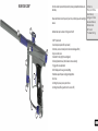
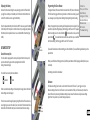
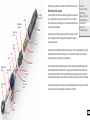
Using a loader with your Clone
Your Clone marker can operate using any commercially available loader. The software and beam sensor will compensate for the speed of the
hopper, ensuring that the marker fires as quickly as the loader allows.
Twist lever clockwise to
tighten the cam lever
system
All Clone markers are equipped with a cam lever clamping feed tube.
This system allows the easy installation and removal of your loader. You
will need to adjust the feed tube to suit the loader that you have.
Installing a loader onto your Clone
Open the cam lever as shown. This should allow your loader neck to fit
into the feed tube as shown. If your loader does not fit into the feed
tube, then you may have to loosen cam lever - this is done by rotating
the cam lever (anticlockwise). Once your loader is pushed all the way
down into the feed tube, close the cam lever. If your loader is loose,
you may need to open the cam lever, and tighten it (by turning clockwise) to adjust the cam system to hold your hopper tightly. Only ever
adjust your cam lever by one turn at a time to prevent overtightening.
DO NOT OVER TIGHTEN YOUR FEED CLAMP! OVERTIGHTENING MAY RESULT IN
DAMAGE TO YOUR LOADER OR CLAMP.
Removing your loader
Open the clamp by swinging the lever on its hinge. This will loosen the loader and allow you to remove it easily. If it
does not remove easily, then it means that you have the cam lever overtightened.
USING YOUR CLONE
To get the most out of your marker, make sure that you follow the instructions in this
section to ensure that the marker is adjusted correctly.
Adjusting the velocity
The velocity of the Clone is adjusted via an adjustment screw on the bottom your
inline regulator. To increase velocity, use a 1/8” allen key to turn the adjustment screw
anti clockwise. Always adjust your velocity gently and use a chronograph.
Contents
Know your Clone
Quick Setup
Using your Clone
Advanced Setup
Maintenance
Parts List
Troubleshooting
DO NOT ADJUST YOUR VELOCITY ABOVE 300FPS, AND ALWAYS OBEY LOCAL LAWS
AND REQUIREMENTS.
Adjusting the trigger
Your trigger has three adjustment screws, they are located in the front face of the trigger in the following order from top to bottom:
Increase
- Pull tension
Velocity
- Switch actuation point
- Pull length
CAUTION! WHEN ADJUSTING THE SWITCH ACTUATION SCREW, MAKE CERTAIN
THAT YOU DO NOT ADJUST THE SCREW IN TOO FAR, AS THIS MAY RESULT IN
DAMAGE TO YOUR MICROSWITCH.
Tension
Actuation
Length
You can easily adjust these three screws to personalise the feel of your trigger.
10