1
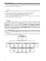
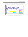
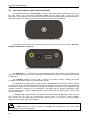
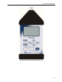
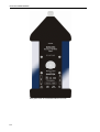
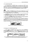
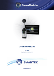
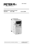
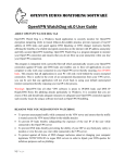
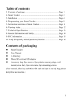
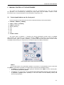
SVAN 953 USER MANUAL
2
MANUAL CONTROL OF THE INSTRUMENT
The control of the instrument is developed in the fully conversational way. User can manage
the operation of the instrument by selecting the proper option from the MENU. Thanks to that,
the number of the control push-buttons of the instrument is reduced to nine.
2.1
Control push-buttons on the front panel
On the front panel of the instrument, there are located the following control push-buttons:
1. <ENTER>, (<MENU>), [<SAVE>],
2. <ESC>, (<CAL>), [<PAUSE>],
3. <SHIFT>, [Markers]
4. <ALT>, (Markers)
5. <>,
6. <>,
7. <>,
8. <>,
9. <START / STOP>.
The name given in brackets (...) denotes the second push-button function which is available
after pressing it in conjunction (or in sequence) with the <SHIFT> push-button. For the first two pushbuttons the name given in square brackets […] denotes also the third push-button function which
is available after pressing it in conjunction (or in sequence) with the <ALT> push-button.
Control push-buttons of the SVAN 953 instrument
<SHIFT>
The second function of a push-button (written in red colour on a push-button) can be used when
the <SHIFT> push-button is pressed. This push-button can be used in two different ways:
•
As SHIFT in the keyboard (e.g. while typing the filename); both SHIFT and the second pushbutton must be pressed in parallel;
•
As 2nd Fun; this push-button can be pressed and released before pressing the second one
or pressed in parallel (while operating in “2nd Fun” mode, see the following notice) with
the second push-button.
2-1
SVAN 953 USER MANUAL
_
<SHIFT> pressed in conjunction with <ALT> enables the user to enter the Markers on the plots
during the measurement.
Notice: The operation of this push button can be set as the “Shift” mode or the “2nd Fun.”
mode in the SHIFT MODE window of the SETUP list (see Chapter with the SETUP list description).
<ALT>
This push-button enables one to choose the third push-button function in case of [<SAVE>] and
[<PAUSE>] push-buttons. In order to select the third function user must press the <ALT> and
the second push-button simultaneously.
<ALT> pressed together with <SHIFT> enables the user to enter the Markers on the plots during
the measurement.
Notice: The simultaneous pressing of the <ALT> and <START / STOP> push-buttons
switches the instrument on and off.
<START / STOP>
This push-button enables one to start the measurement process, when the instrument is not
measuring or to stop it, when the instrument is in course of the measurement. It is also possible to set
such mode of this push-button, in which in order to start or stop the measurements the user has to press
it simultaneously with the <SHIFT> one.
Notice: Change of the <START / STOP> push-button mode is performed in the
SHIFT MODE window of the SETUP list (see Chapter with the SETUP list description).
<ENTER>
This push-button enables one to enter the selected operation mode or to confirm control options.
Some additional functions of this push-button will be described in the following chapters.
(<MENU>)
This push-button (pressed together with the <SHIFT> one) enables the user to enter the main list
containing six sub-lists: FUNCTION, INPUT, DISPLAY, FILE, REPORT and SETUP. Each of
the mentioned above sub-lists consists of the sub-lists, elements and data windows. These main sub-lists
will be detailed described in the following chapters of the manual. Double pressed <MENU> push-button
enters the list containing eight last opened sub-lists. It often speeds up the control of the instrument.
[<SAVE>]
This push-button (pressed together with the <ALT> one) enables the user to save measurement
results as a file in the internal instrument’s memory or on the USB memory stick. There are two available
functions: SAVE NEXT - save a file with the name increased by one (e.g. 02JAN0, 02JAN1, 02JAN3) and
SAVE - save a file with the edited name.
2-2
SVAN 953 USER MANUAL
<ESC>
This push-button closes the control lists, sub-lists or windows. It acts in opposite to the <ENTER>
push-button. When the window is closed pressing the <ESC> push-button, any changes made in it
are ignored in almost all cases.
([CAL])
This push-button (pressed together with the <SHIFT> one) enables the calibration menu in which
user can set the calibration options of the device.
[<PAUSE>]
This push-button enables one to break the measurement process temporarily. The subsequent
pressing of the <PAUSE> push-button deletes the measurement results from the last one second.
The indicator of the measurement time is counted down after each pressing and the measurement result
from the previous second appears on the display. Up to fifteen last seconds of the measurement
can be cancelled in this way.
<>, <>
These push-buttons enable one, in particular, to:
• select the options in an active position in the "horizontal direction" (e.g. filter: Z, A or C, Integration
period: 1s, 2s, 3s, … etc.),
• select the measurement result to be displayed (e.g. PEAK, MAX, MIN, etc.) in One Profile and
3 PROFILES modes of result’s presentation),
• control the cursor in LOGGER and STATISTICS modes of result’s presentation,
• select the position of the character in the text edition (i.e. in the FILE NAME menu),
• switch on/ off the BACKLIGHT of the display (<> and <> pressed together).
(<>, <>)
The <>, <> push-buttons pressed in conjunction (or in sequence) with the <SHIFT> enable one,
in particular, to:
• speed up the changing of the numerical values of the parameters (i.e. the step is increased
from 1 to 10 in the setting of START DELAY),
• insert or delete a character in the text edition modes,
• change the statistics class (the number displayed after the letter L) in One Profile and 3 PROFILES
modes of result’s presentation.
Some other possible reactions of the instrument on the pressing of these push-buttons
will be described in details in the following chapters.
<>, <>
The <>, <> push-buttons enable one, in particular, to:
• change the mode of result’s presentation,
• select the proper character from the list in the text edition mode,
• switch the active sub-list in a list.
• programme the Real Time Clock (RTC) and TIMER.
2-3
SVAN 953 USER MANUAL
_
Some other possible reactions of the instrument on the pressing of these push-buttons
will be described in details in the following chapters.
(<>, <>)
The <>, <> push-buttons pressed in conjunction (or in sequence) with the <SHIFT> enable one,
in particular:
• change the relation between the Y-axis and X-axis of all plots presented on the screen,
• switch the profiles in One Profile and STATISTICS modes of result’s presentation,
• switch the active profile in 3 PROFILES mode of result’s presentation
Some other possible reactions of the instrument on the pressing of these push-buttons
will be described in details in the following chapters.
[Markers]
The Markers enable the user to mark special events, which occurred during the performed
measurements (i.e. the airplane flight, the dog’s barking, the train’s drive etc.). The logger has to be
switched on (path: MENU / INPUT / MEASUREMENT SETUP / LOGGER On) in order to activate
the markers and one or more logger options (LOGGER PEAK, LOGGER MAX, LOGGER MIN,
LOGGER RMS) in profiles have to be chosen (path: MENU / INPUT / MEASUREMENT SETUP /
PROFILE x)). In order to enter the marker the user must press <SHIFT> and <ALT> push-buttons
simultaneously during the measurement. The ENTER MARKER window opens and there are four
available marker numbers. To choose marker number 1 the user must press <> push button (number 2
- <>, number - 3 <> and number 4 - <>).
The ENTER MARKER window closes automatically and chosen marker is activated (after pressing
<SHIFT> + <ALT> again active marker number will be highlighted). In order to switch off the marker,
the user has to open the ENTER MARKER window and press this push-button, which refers to the marker
to be switched off.
The current state of the markers is indicated in the logger’s file (cf. App. B for details) and can be
used to show them using dedicated presentation software.
Display with the “MARKERS” (after pressing <ALT> and <SHIFT> together)
Displays with the activated markers
2-4
SVAN 953 USER MANUAL
The exemplary presentation of the markers on the time history plot is shown below (to view a plot
with markers the user has to transfer data to the proper software).
80
70
60
50
Leq
Marker 1
40
Marker 2
Marker 3
30
Marker 4
20
13:30:00 13:30:09 13:30:17 13:30:26 13:30:35 13:30:43 13:30:52
Time history plot with the indication of the active markers
2-5
SVAN 953 USER MANUAL
2.2
_
Input and output sockets of the instrument
The measurement input, called Preamp. is placed in the centre of the instrument’s top cover. It is
the TNC socket. The microphone preamplifier SV 12 has the proper plug in with the screw.
After plug in the preamplifier to the measurement input the screw should be twisted to the light resistance.
The full description of the signals connected to the sockets is given in the Appendix C.
Top cover of the SVAN 953 instrument in 1:1 scale
In the bottom cover there are four sockets, placed from the right to the left as follows: Ext. Pow.,
USB Host, USB Device and Ext. I/O.
Bottom cover of the SVAN 953 instrument in 1:1 scale
The USB Device 1.1 interface is the serial interface working with 12 MHz clock. Thanks to its
speed it is widely used in all PC. In the instrument the standard 4-pins socket is used described in details
in Appendix C.
The USB Host interface can be used to connect the external storage, enabling the device
to register virtually infinite sequence of measurement results.
The additional multi purpose input / output socket, called Ext. I/O, is a RCA Jack (“Cinch”) socket.
On this socket, in the case when the Analogue Output functionality is selected, the signal from the input of
the analogue / digital converter (before the correction) is available. This signal can be registered using
magnetic recorder or observed on the oscilloscope. The Digital Input as another functionality serves
as the external trigger, while the Digital Output is used to generate the trigger pulse or alarm pulse
from the instrument.
To the Ext. Pow. socket located on the bottom cover of the instrument dedicated for the connector
type 5.5 / 2.1 mm the user can connect the external power (110 V / 220 V mains) adapter.
The instrument can be charged from the external DC source (from 6 V to 15 V). The current consumption
depends on the voltage of the power supplier.
Notice: Switch the power off before connecting the instrument to any other device
(e.g. a printer or a Personal Computer).
2-6
SVAN 953 USER MANUAL
Front panel of the SVAN 953 instrument in 1:1 scale
2-7
SVAN 953 USER MANUAL
_
Rear panel of the SVAN 953 instrument in 1:1 scale
2-8