1
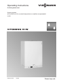
Operating instructions
VIESMANN
for the system user
Heating system
with control unit for constant temperature or weather-compensated
mode
VITODENS 111-W
5618 673 GB
4/2012
Please keep safe.
Safety instructions
For your safety
Please follow these safety instructions closely to prevent accidents and material losses.
Safety instructions explained
Danger
This symbol warns against the
risk of injury.
!
Please note
This symbol warns against the
risk of material losses and environmental pollution.
Note
Details identified by the word "Note" contain additional information.
Target group
These operating instructions are for the
heating system user.
This unit is not designed to be used by
persons (including children) with limited
bodily, sensory or mental capacities, or
lacking experience and/or lacking knowledge, unless they are supervised by a
person responsible for their safety, or
have received instructions from such a
person as to how to use the unit.
Please note
Children should be supervised.
Ensure that children do not play
with the unit.
If you smell gas
Danger
Escaping gas can lead to explosions which may result in serious
injury.
■ Do not smoke. Prevent naked
flames and sparks. Never
switch lights or electrical appliances ON or OFF.
■ Close the gas shut-off valve.
■ Open windows and doors.
■ Remove all people from the
danger zone.
■ Notify your gas or electricity
supplier and your heating contractor from outside the building.
■ Shut off the electricity supply to
the building from a safe place
(outside the building).
5618 673 GB
!
Danger
Incorrectly executed work on the
heating system can lead to lifethreatening accidents.
■ Work on gas appliances must
only be carried out by a registered gas fitter.
■ Work on electrical equipment
must only be carried out by a
qualified electrician.
2
Safety instructions
For your safety (cont.)
If you smell flue gas
Danger
Flue gas can lead to life-threatening poisoning.
■ Shut down the heating system.
■ Ventilate the boiler room.
■ Close all doors in the living
space.
In case of fire
Ancillary components, spare and
wearing parts
!
Please note
Components that are not tested
with the heating system may lead
to damage to the heating system,
or may affect their various functions.
Installation or replacement work
must only be carried out by qualified personnel.
Danger
Fire creates the risk of burning
and explosions.
■ Shut down the heating system.
■ Close the shut-off valves of the
fuel lines.
■ Use a tested fire extinguisher,
class ABC.
Boiler room requirements
5618 673 GB
!
Please note
Incorrect ambient conditions can
lead to damage to the heating
system and put the safe operation at risk.
■ Ensure ambient temperatures
above 0 ºC and below 35 ºC.
■ Prevent air contamination by
halogenated hydrocarbons
(e.g. as contained in paints,
solvents or cleaning fluids) and
excessive dust (e.g. through
grinding/polishing work).
■ Avoid continuously high humidity levels (e.g. through frequent
drying of washing).
■ Never close existing ventilation
apertures.
3
Index
Index
Introductory information
Commissioning.....................................................................................................
Terminology..........................................................................................................
Your system is preset at the factory.....................................................................
Energy saving tips................................................................................................
5
5
5
5
Where to find the controls
Summary of controls and indicators.....................................................................
■ Control and display elements............................................................................
■ Indicators on display.........................................................................................
Operating mode of the heating system................................................................
■ Operation without room temperature control unit..............................................
■ Operation with room temperature control unit...................................................
■ Weather-compensated mode............................................................................
7
7
7
8
8
8
8
Start-up/shutdown
Starting the heating system.................................................................................. 9
Shutting down the heating system....................................................................... 9
■ Switching the Vitodens off with frost protection................................................ 9
■ Shutting down the heating system.................................................................... 10
Settings
Heating................................................................................................................. 11
Domestic hot water............................................................................................... 11
Displays
Heating water temperature................................................................................... 12
What to do if...
System characteristics......................................................................................... 13
Fault indicator on display...................................................................................... 14
Reset burner fault (Reset).................................................................................... 14
15
15
15
16
Appendix
Terminology.......................................................................................................... 17
Keyword index.................................................................................................... 19
4
5618 673 GB
Servicing
Cleaning...............................................................................................................
Inspection and maintenance................................................................................
■ Boiler.................................................................................................................
■ Drinking water filter (if installed)........................................................................
Introductory information
Commissioning
The commissioning and matching up of
the control unit to local conditions and
the building characteristics must be carried out by your heating contractor.
g Gas council no.
Rated heating
Gas council no.
output range
kW
6.5 - 26
47-819-24
8.8 - 35
47-819-25
Terminology
To provide you with a better understanding of the functions of your Viessmann
control unit some terminology is
explained.
The terms are marked as follows.
Further information can be found
in chapter "Terminology" in the Appendix.
Your system is preset at the factory
The control unit is preset at the factory
for standard operation.
Your heating system is therefore ready
for operation. You may change the factory setting in accordance with individual
requirements.
Energy saving tips
Utilise the setting options for the control
unit and remote control (if available).
Central heating
5618 673 GB
■ Room temperature:
Never overheat your rooms. Every
degree of room temperature reduction
saves up to 6 % of your heating bills.
Set your room temperature no higher
than 20 ºC.
■ Operating modes:
5
Introductory information
Energy saving tips (cont.)
■
■
■
■
If you do not require central heating,
select one of the following operating
modes:
– If you do not wish to heat rooms in
summer but require domestic hot
water, set rotary selector "tw" (see
page 11) and turn rotary selector
"tr" to "0".
– If you require neither central heating
nor DHW for a prolonged period, set
rotary selectors "tr" and "tw"to
"0" (see pages 11 and 11).
Ventilation:
To ventilate, open the windows fully for
a brief time and meanwhile close the
thermostatic valves (if there is no
domestic ventilation system installed).
Roller shutters:
Close roller shutters (where installed)
at dusk.
Thermostatic valves:
Ensure that thermostatic valves are
properly set.
Radiators:
Never cover radiators or thermostatic
valves.
DHW heating
5618 673 GB
■ DHW temperature:
Never set the DHW cylinder temperature excessively high (see page 11).
■ DHW consumption:
Consider showering instead of running
a bath. A shower generally uses less
energy than a full bath.
6
Where to find the controls
Summary of controls and indicators
Control and display elements
A
B
2
1
r
3
0
C
D
E
°C
60
4
A
bar
r
A Pressure gauge
B Display
C tw Rotary selector "DHW temperature "
D tr Rotary selector "heating water
temperature" and "reset"
E ON/OFF switch
Indicators on display
AB
r
C
°C
8:8:8
°F
A
HG
SERV
F
E
Heating mode
DHW heating
Display value or fault code
Temperature in °C
Service setting active (only for contractors)
F Current burner output
G Burner in operation
H Fault
5618 673 GB
A
B
C
D
E
D
7
Where to find the controls
Operating mode of the heating system
Operation without room temperature control unit
Further information can be found
in chapter "Terminology" in the Appendix.
The required heating water temperature
can be set with the rotary selector
"tr" (see page 11).
Operation with room temperature control unit
Further information can be found
in chapter "Terminology" in the Appendix.
Please make any adjustments to the
connected room temperature control unit
using the relevant operating instructions.
Note
The heating water temperature must be
set sufficiently high using the rotary
selector "tr" for the desired room temperature to be reached.
Weather-compensated mode
Further information can be found
in chapter "Terminology" in the Appendix.
5618 673 GB
In weather-compensated mode, the
boiler water temperature is regulated
subject to the outside temperature.
Rotary selector "tr" enables you to
increase or reduce the room temperature.
8
Start-up/shutdown
Starting the heating system
We recommend you contact your local
heating contractor if you are planning to
start up a heating system that has not
been used for a long period.
2
1
3
0
4
bar
1. Check the pressure of your heating
system on the pressure gauge.
Minimum system pressure
0.8 bar.
If the system pressure is too low,
please notify your heating contractor.
2. With conventional flue operation
(combustion air is taken from the
boiler room):
There must be fixed permanent ventilation into the boiler room.
3. Open the gas shut-off valve.
4. Switch on the ON/OFF switch.
Your heating system and room temperature control unit (if connected)
are now ready for operation.
Shutting down the heating system
Switching the Vitodens off with frost protection
If you do not wish to use your boiler for
several days you can switch the unit
off.
5618 673 GB
Further information can be found
in chapter "Terminology" in the Appendix.
9
Start-up/shutdown
Shutting down the heating system (cont.)
Turn both rotary selectors to "0".
Frost protection is now active for the
boiler.
r
Note
Frost protection for the entire heating
system - see operating instructions for
the room temperature control unit.
Shutting down the heating system
Shut down your heating system completely if it will not be needed for a long
period of time (several months).
We recommend you contact your local
heating contractor if you are planning to
shut down your heating system for long
periods. Your heating contractor can
then take any necessary action, subject
to requirements, e.g. system frost protection or preserving the heating surfaces.
1. Close the gas shut-off valve and safeguard against unauthorised reopening.
5618 673 GB
2. Switch off the ON/OFF switch.
The power to the system is now
switched off.
Note that the system is no longer
frost-protected.
10
Settings
Heating
Further information can be found
in chapter "Terminology" in the Appendix.
Switching on:
Move rotary selector "tr" to the
required heating water temperature.
Note
If a room temperature control unit is connected, use this unit to set the desired
room temperature (see page 8).
If central heating is active, the display
shows "r".
r
Switching off:
Turn rotary selector "rt" to "0".
Domestic hot water
Further information can be found
in chapter "Terminology" in the Appendix.
Select the DHW temperature in accordance with your personal requirements
(e.g. for showering).
Switching on:
Move rotary selector "tw" to the
required DHW temperature.
If DHW heating is active, the display
shows "w".
5618 673 GB
Switching off:
Turn rotary selector "tw" to "0".
11
Displays
Heating water temperature
Further information can be found
in chapter "Terminology" in the Appendix.
°C
60
The boiler water temperature appears on
the display at all times during operation.
The heating water temperature is
roughly equal to the boiler water temperature.
5618 673 GB
A
12
What to do if...
System characteristics
What to do if...
Cause
... the heating system will not No mains voltage
start
Rotary selector
"tr" is on "0"
Fuse/MCB in the
power distribution
board (domestic
mains fuse) or in
control unit has
blown/responded
... the burner is not started or No gas available
starts intermittently
... the burner fails to start;
fault message "U" is displayed
5618 673 GB
… the burner shuts down
even if the rooms have not
reached their required temperature
... the rooms have not
reached the required temperature, even though the
burner is operational
… DHW temperature is too
low
Remedy
Switch on the ON/OFF switch
Setting the desired heating water temperature (see page 11)
Notify your local heating contractor
Open the gas shut-off valve and
if necessary check with your
gas supply utility
Control unit fault
Check the fault code on the display. Notify your local heating
contractor and state the fault
code.
False start
Reset burner fault (see
page 14) – if this attempt to
start also fails, notify your heating contractor
Water shortage
Notify your local heating contractor.
Fault in the ventila- Notify your local heating contion air supply or flue tractor
system
Heating water tem- Raise the heating water temperperature or required ature with rotary selector
room temperature is "tr" (see page 11) or raise reset too low
quired room temperature (see
room temperature control unit
operating instructions)
Air in the heating
Bleed radiators
system
DHW priority
Wait until the DHW cylinder has
been heated up
Circulation pump
Notify your local heating confaulty
tractor
DHW temperature is Set the desired DHW temperaset too low or rotary ture
selector "tw" is on
"0"
13
What to do if...
Fault indicator on display
Any fault in the heating system will be
shown on the display.
You can check the fault code on the display and then notify your heating contractor accordingly. This allows the heating contractor to better prepare for the
service call and may save additional
travelling costs.
f2
Reset burner fault (Reset)
1. Turn rotary selector "rt" to "U
RESET" for less than 2 s, then back
into the control range.
2. If the attempt to start fails, contact
your heating contractor with the fault
code.
5618 673 GB
r
14
Servicing
Cleaning
All appliances may be cleaned with a
commercially available domestic cleaning agent (non-scouring).
Inspection and maintenance
The inspection and maintenance of a
heating system is prescribed by the
Energy Savings Ordinance [EnEV - Germany] and the DIN 4755, DIN 1988-8
and EN 806 standards.
Regular maintenance ensures troublefree, energy-efficient and environmentally responsible heating. For this, it is
recommended that you take out an
inspection and maintenance contract
with your local contractor.
Boiler
Increasing boiler contamination raises
the flue gas temperature and thereby
increases energy losses. All boilers
should therefore be cleaned annually.
Logbook
5618 673 GB
Please ensure that you have a Logbook
supplied with your appliance. This Logbook should be completed by your installer to verify that the correct installation
and commissioning procedure was followed.
Failure to complete the Logbook may
result in difficulties should a problem
arise with your appliance during the
guarantee period. This Logbook forms
part of the industry's Benchmark code of
practice for the installation, commissioning and servicing of central heating systems.
All Gas Safe Registered Installers carry
a ID card and have a registration number. Both should be recorded in your
Logbook. You can check your installer is
Gas Safe registered by calling GasSafe
register on +44 (0)800 408 5500 or visit
the website www.gassaferegister.co.uk
15
Servicing
Inspection and maintenance (cont.)
Drinking water filter (if installed)
Further information can be found
in chapter "Terminology" in the Appendix.
5618 673 GB
For hygiene reasons
■ replace filter element on non-backwashing filters every six months (visual inspection every two months)
■ on backwashing filters, backwash
every two months
16
Appendix
Terminology
Constant temperature mode
Open flue operation
In constant temperature mode, the heating water is constantly (continuously)
heated to the selected boiler water temperature.
The combustion air is drawn from the
room where the boiler is installed.
Operating modes
The combustion air is drawn from outside the building.
You can select the following operating
modes:
■ When r and w are selected:
The rooms are heated. DHW is heated
(winter mode).
■ When w is selected:
DHW is heated but there is no central
heating (summer mode).
■ When r is selected:
The rooms are heated but there is no
DHW heating.
■ When r and w are set to "0":
Frost protection for the boiler and
DHW cylinder is active, no central
heating, no DHW heating (standby
mode).
Balanced flue operation
Room temperature-dependent operation
A room temperature control unit captures the room temperature and compares this with the required room temperature you selected. If the room temperature is lower than the required value,
the boiler is switched on; if the room temperature is higher than the required
value, the boiler is switched off.
Please make any adjustments to the
connected room temperature control unit
using the relevant operating instructions.
The temperature of the heating water
that flows to the radiators (roughly equal
to boiler water temperature).
Note
The heating water temperature must be
set sufficiently high using the rotary
selector "tr" for the desired room temperature to be reached.
Boiler water temperature
Safety valve
The heating water in the boiler (boiler
water) is heated to the temperature
selected at the control unit. This temperature is described as boiler water temperature.
A safety device that must be installed by
your heating contractor in the cold water
pipe. The safety valve opens automatically to prevent excess pressure in the
DHW cylinder.
5618 673 GB
Heating water temperature
17
Appendix
Terminology (cont.)
Drinking water filter
A device that removes solids from the
water. The drinking water filter is installed in the cold water pipe upstream of the
DHW cylinder or the instantaneous
water heater.
Flow temperature
The temperature of the heating water
that flows to the radiators (in the flow
line). Accordingly, the temperature of the
heating water that flows from the radiators to the boiler (in the return line) is
described as the return temperature.
Weather-compensated mode
5618 673 GB
In weather-compensated mode, the flow
temperature is controlled according to
the outside temperature. This means
that no unnecessary heat is generated in
order to heat the rooms to the required
room temperature you selected.
The outside temperature is captured and
transmitted to the control unit by a sensor fitted outside the building.
18
Keyword index
Keyword index
C
Changing the temperature.............8, 11
Cleaning information..........................16
Commissioning....................................5
Controls................................................7
D
DHW temperature..............................11
Display.................................................7
Display elements..................................7
Drinking water filter............................16
M
Maintenance......................................15
Maintenance contract.........................15
N
Notice of completion............................5
R
Reset..................................................14
Room temperature...............................8
E
Error (fault).........................................14
S
Starting.................................................9
Switching off.........................................9
F
Fault...................................................13
Frost protection....................................9
T
Temperature display..........................12
Terminology.......................................17
H
Heating water temperature................11
W
Weather-compensated mode.........8, 18
5618 673 GB
I
Inspection...........................................15
19
Viessmann Werke GmbH&Co KG
D-35107 Allendorf
Telephone: +49 6452 70-0
Fax: +49 6452 70-2780
www.viessmann.com
20
Viessmann Limited
Hortonwood 30, Telford
Shropshire, TF1 7YP, GB
Telephone: +44 1952 675000
Fax: +44 1952 675040
E-mail: [email protected]
Subject to technical modifications.
Contact your local contractor if you have any questions regarding the maintenance
and repair of your system. You may, for example, find local contractors on the internet
under www.viessmann.com.
5618 673 GB
Your contact