1
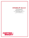
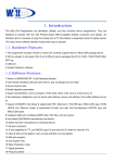
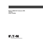
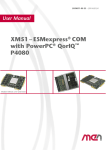
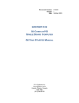
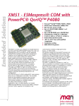
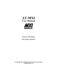
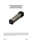
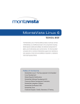
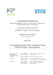
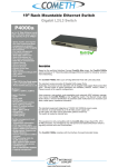
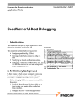
Data Sheet VPX6-187 Freescale™ QorIQ™ P4080 Single Board Computer Features Freescale QorIQ™ P4040/4080 up to 1.5 GHz --Four or Eight e500mc processor cores --Each core has 64 KB L1 cache --Each core has 128 MB L2 cache with ECC --Two DDR3 memory controllers with ECC --Four Gigabit Ethernet controllers --Two USB ports --Serial I/O controller --Two I2C channels --One PCI Express® (PCIe) interface --One Serial RapidIO® (SRIO) interface --Integrated DMA controllers Up to 4 GB DDR3 SDRAM with ECC --Dual-channel memory controllers 256 or 512 MB flash with write protection Permanent Alternate Boot Site (PABS) provides backup boot capability 512 KB FRAM 8 GB onboard NAND flash VITA 46 core fabric with both SRIO and PCIe interfaces OpenVPX™ Ready* Fabric Configurations --Four x4 SRIO interfaces up to 3.125 GB/s, or two PCIe and two SRIO interfaces backwards compatible with the 185 --Four x2 SRIO interfaces up to 3.125 GB/s plus two x4 PCIe Four Gigabit Ethernet interfaces --1 - Front panel - Standard product air-cooled only (configurable to backplane) --3 - backplane - Option for dual 1000BaseBX * T h i s p roduct has been designed in accordance to the draft spec and s h o u l d f i t i n s e l e c t e d OVPX backplane profiles, since the draft spec is still not for m a l i z e d a s a n A N S I s t a ndard, things are subject to change. Two XMC/ PMC mezzanine sites --One 133 MHz PCI-X PMC or 8-lane PCIe XMC --One 8-lane PCIe XMC Four asynchronous EIA-232 serial ports Up to 4 HDLC/SDLC-capable sync/async EIA-232/422/485 serial channels Up to 14 LVTTL discrete I/O signals Up to 16 EIA-422/485 differential discrete signals (eight inputs, eight outputs) Multi-board synchronous clock Two channel MIL-STD-1553 option Two channel SATA 1.0 option Two USB 2.0 ports Six general-purpose 32-bit timers in Core Functions FPGA Two 4-channel DMA engines Eight global timers organized as two groups of four in the P4080 Multicore Programmable Interface Controller (MPIC) Two avionics-style watchdog timers Real-time Clock with VBAT switch over Eight temperature sensors Supports 5 V or 12 V operation Continuum Software Architecture (CSA) firmware with extensive diagnostics Wind River® VxWorks® 6.8+ Workbench® 3.x support Wind River® GPP Linux® 4.x INTEGRITY® available from Green Hills® Software Range of air- and conduction-cooled ruggedization levels available Learn More Web / sales.cwcembedded.com Email / [email protected] cwcembedded.com Overview The VPX6-187 is the next generation of modules from Curtiss-Wright Controls Embedded Computing to employ the new open-architecture VITA 46 standard. VITA 46, also known as “VPX” was collaboratively developed by COTS industry leaders which included prime military integrators to marry high-speed serial (HSS) interconnect such as SRIO and PCIe. It is well suited to the military/aerospace which can take advantage of and utilize this form factor and feature set in their demanding applications. The VPX6-187 provides single board computer (SBC) functionality to the Curtiss-Wright VPX family that includes quad-processor DSP, FPGA accelerator and XMC/PMC carrier modules. Available in a full range of environmental build grades, the VPX6-187 is targeted to the challenging data- and digital signal-processing needs of tactical aircraft, armored vehicles and harsh environment naval systems. For retrofit and technology insertion applications, the VPX6-187 offers a superset of the I/O features of earlier generations of Curtiss-Wright's VME 18x PowerPC™ SBCs. As a member of Curtiss-Wright's continuously evolving stream of PowerPC SBCs including the SVME/DMV-179, 181, 182, 183, 184, and the VPX6-185, the VPX6-187 supports the life-cycle model of successive technology insertions throughout a platform’s lifetime. The VPX6-187is based on Freescale's high-performance QorIQ P4040/4080 SOC multi-core processor. Available in versions with up to eight Power Architecture® Cores running up to 1.5 GHz, and up to 4 GB of high-bandwidth DDR3 SRAM, the VPX6-187 provides high-performance processing, the massive 10 GB/s bandwidth of VPX and a long list of features and I/O interfaces to satisfy the most demanding requirements of embedded computing. The VPX6-187 will occupy a standard 0.8” slot and is also available in the VITA 48 (VPX REDI) format with covers to support two level maintenance LRM requirements. Air-cooled variants are delivered with 1" front panels. Figure 1: VPX6-187 VPX Block Diagram MicroWire SEPROM NVRAM Core Functions FPGA PABS NOR Flash Temp Sensors RTC Voltage/ Current Sensors IPMI Interface Personality Module - EIA-232/422/485 - MIL-STD-1553 - SATA - TTL and Differential Discretes Local PCI 12C NAND PCIe PCIePCI 1 DDR3 SDRAM Freescale Power Architecture MPC4080 Processor @ 1.5 GHz DDR3 SDRAM IPM I/O 4 4 SRIO Switch PCIe Gen 2 Switch 8 8 4 4 4 PCIePCI-X 4 4 2 Pn5 F C 2 EIA-232 GbE 1000Bx USB VITA 42 XMC 1 Pn6 40 38 SE Diff 2 PCI 4x 4-lane SRIO 2x 4-lane PCIe Pn5 Software configurable VITA 42 PMC/ XMC 2 Pn4 64 Pn6 24 SE Diff P2 (PCIe only) AB CD Curtiss-Wright Controls Embedded Computing / cwcembedded.com Eight Core Power Architecture Freescale QorIQ P4040/4080 PowerPC VPX Module Format The Versatile Performance Switching (VPX) module format, governed by the VITA 46 specification and the associated VITA 48 Ruggedized Enhanced Design Implementation (REDI) was established to address the fundamental requirement to provide open-architecture modules that incorporate the HSS interconnect technology that has become pervasive in high-performance computing. The VPX standard was developed by the leading providers of military COTS modules to address the major issue of HSS interconnect, as well as incorporating numerous improvements learned after years of integrating VME and CompactPCI® (CPCI) modules. The VPX standard, in short provides: The processing function of the VPX6-187 is provided by the QorIQ P4040/4080. The P4040/4080 SOC includes the following function and features used on the VPX6-187: Four or eight e500mc Power Architecture cores, each with a backside 128 KB L2 Cache with ECC --Three levels of instructions --User --Supervisor --Ultravisor --Independent boot and reset --Secure boot capability 3U and 6U Eurocard form factors preserve chassis Dual front side 1 MB L3 Caches with ECC. One associated Support four x4 serial interfaces as the primary fabric Support 128 differential pairs for modern high-speed CoreNet bridges between the CoreNet fabric the mechanical designs with each memory controller I/Os, datapath accelerators, and high and low-speed peripheral interfaces interfaces such as DVI, SATA, SFPDP, SAS and custom sensor interfaces Four 1 GbE controllers Two 64-byte DDR2/DDR3 SDRAM memory controllers Optional support of VME for interoperability with legacy equipment (not supported by all VPX cards) with ECC Support of higher power modules and improved cooling Improved logistics with two-level maintenance and Multi-core Programmable Interrupt Controller Four I2C controllers Four 2-pin UARTs Two 4-channel DMA engines Enhanced local bus controller (eLBC) One PCIe 2.0 controllers/ports One SRIO 1.2 controllers/ports Datapath Acceleration Architecture incorporating keying The VPX module format provides many benefits to integrators of high-performance multi-processor systems for radar, electro-optical and signal intelligence applications. In particular SRIO is suited to high-bandwidth communications between processors in a VPX system, while PCIe functions as a fast connection between processors and the new generation of XMC modules which can easily be placed on VPX format carrier cards. acceleration for the following functions --Packet Parsing, classification, and distribution --Queue Management for scheduling, packet sequencing, and congestion management --Hardware Buffer Management for buffer allocation and de-allocation --Encryption/decryption (SEC 4.0) --Regex Pattern Matching (PME 2.0) Table 1 compares the key characteristics (and performance gains) of the P4080 to the previous generation VPX6-185 SBC based on the MPC864x processor. 3 Curtiss-Wright Controls Embedded Computing / cwcembedded.com VPX Fabric Interface Table 1: VPX6-187 to VPX6-185 Comparison 185 187 Processor Single MPC8641D Single P4080 Number Cores 2x e600 cores @ 1.2 GHz 8x e500mc @ 1.5 GHz Memory banks x2, DDR2 @ 500 MHz x2, DDR3 @ 1066 MHz Memory bandwidth 8.6 GB/s (DDR266) 17.05 GB/s (DDR533) I/O fabric 4x SRIO or 2x SRIO, 2x PCIe 4x SRIO or 2x SRIO, 2x PCIe or 4x SRIO + 2x PCIe XMC Sites 1 x8 PCIe + 1 x4 PCIe 2 x8 PCIe PMC Sites 2 PCI-X 1x PCI-X XMC/PMC Site P64S + X12D P64S + X12D XMC Sites - X8D + 12D + 38S The VPX6-187 provides users with the option of using either SRIO or PCIe interfaces to connect with other VPX cards in a system be they payload or expansion cards. SRIO is suited for processor to processor or payload to payload communications and would be used to build a system with the VPX6-185, VPX6-187, CHAMP-AV6 and CHAMP-FX2 family of VPX products. PCIe is suited to connecting with PCIe and PCI-based peripheral devices. PCIe interfaces are designed to run at either 2.5 GHz or 5 GHz dependent on the pinout variant. SRIOs communicate at 3.125 GHz. The VPX-187 makes use of its PCIe fabric interfaces to support the VPX6-215 ExpressReach XMC/PMC carrier card. The ExpressReach allows users to easily add extra XMC/PMC modules into a system by extending the local PCIe fabric of the VPX-187 across a VPX backplane. See Figure 2, VPX System using SRIO and PCIe. The VPX6-187 provides two fabric ports which may be configured to operate as SRIO or PCIe and two fabric ports that operate permanently as SRIO. The configuration of the ports is controlled by parameters stored in non-volatile memory. Changes to the port configuration are made via the CSA firmware user interface. A system reboot is required to affect any changes to the port configuration. I/O Routing Figure 2: VPX System with mixed PCI and SRIO CHAMP-AV6 Proc Node Proc Node Proc Node VPX6-187 Proc Node VPX6-185 Proc Node SRIO ExpressReach Carrier ExpressReach Carrier PCIe/PCI PCIe/PCI Proc Node PCIe SRIO PCIe SRIO Mux SRIO connections PCIe/PCI Mux "Disconnected" SRIO to PCIe links PCIe PCIe/PCI PCIe/PCI PCIe PCIe/PCI PCIe connections 4 Curtiss-Wright Controls Embedded Computing / cwcembedded.com Proposed OpenVPX Profile Support NAND Flash The VPX6-187 has been designed to be OpenVPX Ready*. Please contact factory for information on proposed slot profiles. The VPX6-187 comes configured with 8 GB of NAND flash. Permanent Alternate Boot Site (PABS) PABS provides a backup boot capability in the event that the firmware in the main flash becomes corrupted. This can occur because of an error during reprogramming or an incorrect image being loaded. PABS provides users with a convenient mechanism to recover from corruption of the main NOR flash without removing the card from the system in which it is installed. An on-board jumper and a backplane signal (ALT_BOOT) are provided to cause the card to boot from PABS, thus allowing a user to reinstall the standard firmware load. The PABS feature guarantees that a card will never need to be removed from a system to perform NOR flash updates. DoubleData Rate (DDR3) SDRAM The VPX6-187 has two independent DDR3 memory controllers supporting two banks of DDR3 SDRAM. The VPX6-187 may be fitted with 1 GB, 2 GB or 4 GB of DDR3 SDRAM. The DDR3 interface operates at a rate up to 1066 MHz resulting in a peak bandwidth of 8.6 GB/s per memory bank, 17.2 GB/s total. To preserve data integrity, the SDRAM is provided with ECC circuitry that detects and corrects all single-bit data errors, detects all double-bit errors, and detects all 3-bit and 4-bit errors within the same nibble. The SDRAM is accessible from the processor and from the PCIe and SRIO interfaces. Subject to the configuration of BSP settings controlling the memory management of the P4040/4080 processor, the memory can be accessed from other boards via SRIO, local XMC/PMC devices and remote XMC/PMC devices on ExpressReach carrier cards. FRAM A Ramtron FM22L16 Ferroelectric Random Access Memory (FRAM) provides fast, non-volatile storage of mission state data that must not be lost when power is removed. FRAM reads and writes like standard SRAM and as with all FRAM devices, writes occur at bus speed and are immediately non-volatile. The FRAM memory is non-volatile due to its unique ferroelectric memory process which means that data is retained after power is removed. It provides data retention for over 10 years. Fast write timing and high write endurance make FRAM superior to other types of memory. The FM22L16 includes a low voltage monitor that blocks access to the memory array when VDD drops below a critical threshold. The memory is protected against an inadvertent access and data corruption under this condition. The device also features software-controlled write protection. NOR Flash Memory The VPX6-187 is available with 256 MB or 512 MB of flash memory. The flash will retain data for 20 years at +85°C. Note: these figures assume the sector the data is in has less than 1,000 erase cycles. The data retention drops as erase cycle count increases. After 10,000 cycles, data retention is for 10 years. After 100,000 cycles, data corruption will likely be noticeable in one year. Read performance of the flash array is optimized in order to minimize system boot up time for applications such as avionics mission computers where fast restarts after power interruptions are critical. Non-volatile Memory Security The VPX6-187, as well as other Curtiss-Wright Continuum Architecture products, provides for the management of nonvolatile memory devices in classified circumstances. All of the non-volatile devices, flash, PABS flash, FRAM and FPGA PROM may be individually write-protected by a hardware jumper. The jumpers may be visually inspected to conform to security procedures. To facilitate with the management of sealed-box systems, a backplane signal (NVMRO) may be asserted to over-ride the hardware write protection. The CSA firmware of the VPX6-187 provides non-volatile scrub functions to perform a secure erase per NISPOM requirements. For absolute security against inadvertent flash programming or corruption, a hardware jumper is provided to disable writing to flash. The CSA firmware of the VPX6-187 provides flash programming functions with support for downloading flash images over Ethernet. See the separate CSA firmware data sheet for details. See the Non-volatile Memory Security section for more information on write protection and scrub features. * T h i s product has been designed i n a c c o r dance to the draft spec and s h o u l d f i t in selected OVPX backplane p r o f i l e s , since the draft spec is still n o t f o r m alized as an ANSI standard, t h i n g s a r e subject to change. 5 Curtiss-Wright Controls Embedded Computing / cwcembedded.com The VPX6-187 I/O System Four EIA-232 Serial Ports The VPX6-187 features a large number of I/O interfaces including EIA-232, EIA-422/485 serial, USB, Ethernet, MIL-STD-1553, SATA, TTL and differential discrete I/O. The details of the I/O interfaces are described in the following sections. The VPX6-187 provides for an I/O expansion facility with the inclusion of the Interface Personality Module (IPM). The IPM concept, carried forward from the VME182,183 and 184 SBCs as well as the VPX6-185, is a connectorized subassembly that can either simply provide physical-level transceivers for controller devices implemented in the Core Functions FPGA or it can host PCI peripherals such as a SATA interface device. Some of the optional I/O features are implemented with IPM modules. Refer to Table 2 for a summary of the I/O configurations that are available on the VPX6-187. All VPX6-187 configurations have a minimum of four EIA232 serial channels. The EIA-232 serial ports (channels 1, 2, 7, 8) support asynchronous communications with one transmit and one receive signal. All four ports are connected to both a front panel connector and the backplane connector. One serial port supports the use of the DTR signal to automatically detect the connection of a data terminal and can be used to control the boot-up sequence of the card if desired. The four serial ports are implemented with the P4040/4080's dual DUARTs. The baud rate of all four ports can be set independently from 300 to 115200. Four EIA-232/422/485 Serial Port Option The VPX6-187 is available in configurations with one, two or four additional serial ports (channel numbers 3-6). These additional serial ports are implemented with 85230 Serial Communication Controller (SCC) cores in both the Core Functions FPGA and in all of the IPM modules. All of the serial ports support asynchronous communication with baud rates of 300 to 115200. All of the serial ports support synchronous HDLC/SDLC communications at up to 2.0 MB/s. In synchronous mode a full range of data encoding schemes are supported. (NRZ, NRZI Mark, NRZI Space, FM0, FM1, Manchester, and Differential Manchester) The synchronous ports support separate transmit and receive clock signals and can use internal or external clocking, or clock encoded schemes. All of the serial ports support software selection of either EIA-232 (async only) or EIA442/485 (sync or async) signal levels. See the Differential Discrete I/O section below for information on how the VPX6-187 provides the capability to control each of the EIA422/485 drivers and receivers as differential-mode discrete signals for use as serial control signals or general purpose I/O. See Table 2 for configurations that include the optional 232/422/485 serial channels. Four Gigabit Ethernet Interface, OpenVPX SERDES and Pinout Options The VPX6-187 is equipped with up to four 10/100/1000 Base-TX Ethernet interfaces, all implemented within the P4040/4080. Three of the Ethernet ports are routed to the backplane connector P4. One port is factory configured to be present on the front panel connector (air-cooled cards) for standard product variants or to the backplane connector P4 for customer specific variants (note that this shares XMC Site 1 differential I/O pairs). The Ethernet controllers integrate a number of features designed to minimize processor loading due to Ethernet traffic. These include dedicated DMA engines, support for jumbo packets up to 9 KB, efficient buffer management schemes, checksum calculation for IP, TCP, and UDP, and interrupt coalescence. The VPX6-187 also supports two 1000BaseX (SERDES) Ethernet ports which is available as per OpenVPX slot profile SLT6-PAY4F1Q2U2T. Dual Serial ATA (SATA) Interface Option LVTTL Discrete Digital I/O Option The VPX6-187 optionally provides two SATA 1.0 (1.5Gb/s) interfaces based on the Silicon Image 3124 device. Each interface incorporates several performance-enhancing features such as: The VPX6-187 optionally provides 14-bits of LVTTL compatible discrete digital I/O. Each bit is individually programmable to be an input or output. Each I/O bit is capable of generating an interrupt upon a change of state, programmable to detect either edge. Each bit has a 10K pull-up resistor to 5 V. The output drive current is 24 mA. See Table 2 for configurations that include the optional DIO signals. Independent DMA channel with 2K FIFO Independent command fetch, scatter/gather, and command execution See Table 2 for configurations that include SATA. 6 Curtiss-Wright Controls Embedded Computing / cwcembedded.com Transmit Inhibit input for each channel Bus Controller features: --Highly autonomous bus controller with built-in Differential Discrete Digital I/O The VPX6-187 provides the capability to control each of the EIA-422/485 drivers and receivers as differential-mode discrete signals via registers in the Core Functions FPGA. This allows flexibility in how the drivers and receivers are used. The choice of whether the drivers and receivers are attached to serial ports or used as discrete differential I/O is software selectable on a per-serial channel basis. When configured as discrete differential I/O, the drivers and receivers can be used as serial-line control signals (RTS, CD, etc.) in conjunction with another serial channel, or used as general-purpose differential mode control signals unrelated to serial I/O requirements. Differential discrete inputs can generate an interrupt upon a change of state, with programmable edge direction. Note that if the serial channel physical levels are set to EIA-232, then discrete digital I/O at EIA-232 levels is obtained. message sequence control engine for multi-frame message scheduling, branching, and asynchronous message insertion --Programmable inter-message gap size --Single frame or auto-repeat modes --Automatic retries --Time-tag can be transmitted with Synchronize with Data Mode Code --External Trigger input for each channel Remote Terminal features --Programmable illegalization of RT commands --Busy bit programmable on a sub-address basis --16-bit time-tag option with options of 2, 4, 8, 16, 32, or 64μsec/LSB based on internal clock Two USB 2.0 Ports --External time-tag clock input --Time-tag can be set via Synchronize with Data Mode The VPX6-187 provide two USB ports integrated into the P4040/4080. Each port can handle high-speed (480 MB/s), full-speed (12MB/s), and low-speed (1.5 MB/s) operation. When operating at low-speed or full-speed, each port is managed by independent OHCIcompliant controllers internal to the device. One EHCIcompliant controller manages any ports operating in highspeed mode. Code --External Subsystem Flag input Monitoring Terminal features --Selective message monitor mode, use for selecting monitoring based on RT address, Transmit/Receive bit, and Sub-address --Simultaneous RT and monitor modes The RT address for each channel can be set by software One USB port is accessible on the front panel connector and the other is accessible on the P3 or P4 connector (variant dependent). Each port provides a +5 V output to power external USB devices such as keyboards. A backplane configuration input is provided for each channel that can cause the RT address to be set by subset of the TTL discrete digital I/O lines. To meet the MIL-STD-1760 First Response requirement of an RT response within 150msec, one of the MIL-STD-1553 channels initializes as an RT with the Busy status word bit set. This requires that the MIL-STD-1553 channel be configured to set the RT address in hardware. Two Channel MIL-STD-1553 Option The VPX6-187 provides up to two MIL-STD-1553 channels implemented with DDC 65864 micro-ACE TE devices offering the following key features: Support for MIL-STD-1553A, MIL-STD-1553B Notice 2, Curtiss-Wright's driver software for the VPX6-187’s MILSTD-1553 channels provides a flexible, easy to use, and robust applications programming interface (API). The driver supports BC, RT, and MT modes of operation, and offers a high degree of compatibility to the proven software driver provided for Curtiss-Wright's popular PMC-601 MIL-STD-1553 module. Source code is provided for user reference. The MILSTD-1553 driver for the VPX6-187 is sold separately from the hardware and the VPX6-187 BSPs. and STANAG 3838 protocols BC, RT, MT modes independently selectable for each channel Choice of transformer-coupled (standard) or directcoupled outputs (on a special order basis) MIL-STD-1760 amplitude compliant 64K words of RAM per channel, with parity PCI interface is 33 MHz, 32-bit and supports burst writes with a FIFO for up to one complete MIL-STD-1553 message 7 Curtiss-Wright Controls Embedded Computing / cwcembedded.com Table 2: Summary of I/O Options Mode Front Panel (air-cooled only) EIA-232 Serial channels 1,2,7,8 Serial cable detect Gigabit Ethernet port 4 USB port 2 Card Reset Backplane Connector P1 – P6 #0 (Standard Product) EIA-232 Serial Channels 1, 2, 7, 8 Serial cable detect Gigabit Ethernet ports 1-3 Optional Ethernet port 4 USB port 1 Card Fail output Alternate boot input NVMRO input Reset input XMC1 Pn6 I/O (20 differential pairs + 38 single-ended) PMC2 Pn4 I/O (64 pins) XMC2 Pn6 I/O (12 differential pairs) #6 (Standard Product) Same Same as Mode 0 with additional: EIA-422/485 Serial Channels 3-6 14 DIO #8 (By customer specific request) Same Same as Mode 0 with additional: One dual-redundant MIL-STD-1553 Channel EIA-422/485 Serial Channels 3-4 14 DIO #9 (Standard Product) Same Same as Mode 0 with additional: Two dual-redundant MIL-STD-1553 Channels EIA-422/485 Serial Channels 3-4 14 DIO #11 (Standard Product) Same Same as Mode 0 with additional: MIL-STD-1553 Channel 1 SATA Channels 1-2 EIA-422/485 Serial Channels 3-4 14 DIO #12 (Standard Product) Same Same as Mode 11 but without MIL-STD-1553 Real-Time Clock (RTC) same value by all the boards in the system. The counter can be set to roll-over to a pre-load value and interrupt on rollover. This feature is typically most valuable for debugging and instrumenting multi-board applications code, which can present challenges in coordinating the distribution of data items between processors. The MBSC makes use of the VITA 46 reference clock and does not require any special backplane wiring. See the section on Continuum Insights Multi-processor tools for information on how the MBSC can be used to coordinate timing between multiple boards. A Maxim/Dallas Semiconductor DS3231 RTC chip provides the RTC function. It contains registers for century, year, month, day, hours, minutes, and seconds. The RTC is capable of generating alarm interrupts. The RTC draws its power from 3V3_AUX. In the event of loss of backplane 3V3_AUX power, the RTC will automatically switch over to draw power from the backplane VBAT line (P1-G3). Multi-board Synchronous Clock Extensive Timing Resources The VPX6-187 includes a special purpose counter which may be synchronized with corresponding counters on other boards in the same system. This common time base allows a developer to time-stamp messages and/or data buffers, with the knowledge that the local time is maintained at the The VPX6-187 provides a large number of timing resources to facilitate precise timing and control of system events. The list of available timers is given in Table 3. 8 Curtiss-Wright Controls Embedded Computing / cwcembedded.com Table 3: VPX6-187 Timing Resources Timer Implementation Type Size Maximum Duration Tick Rate/Period PowerPC Time Base Register One per CPU Free Running Counter 64-bit 125 MHz/8nsec 4,676 yrs PowerPC Decrementer One per CPU Presettable, Readable Downcounter 32-bit 125 MHz/8nsec 34.35 sec General Purpose #0-7 P4040/4080 MPIC Presettable, Readable Downcounter with auto-read and stop options, divide by 8, 16, 32 and 64 32-bit Divide 16 114 sec RTC Alarm RTC Alarm Interrupt - - - Watchdog timers Core Functions FPGA Presettable, Readable Downcounter with interrupt or reset on terminal count 25-bit 1 MHz/1usec 33.55 sec System Timers #1-6 Core Functions FPGA Presettable, Readable Downcounter with interrupt on terminal count 32-bit 50 MHz/20nsec 85.9 sec Avionics Watchdog Timers and destination striding. The DMA controllers also feature a bandwidth management feature to allow the user to control the distribution of bandwidth between the four DMA channels. The VPX6-187 provides two watchdog timers. Each watchdog timer is a presettable down-counter with a resolution of 1μsec. Time-out periods from 1msec to 33 seconds can be programmed. Initialization software can select whether a watchdog exception event causes a software interrupt, a processor reset, a card reset or a system reset. Once enabled to cause a reset, the watchdog cannot be disabled. A watchdog event indicator discrete signal is output to the backplane. XMC/PMC Sites The VPX6-187 is equipped with two mezzanine sites. One mezzanine is capable of supporting a IEEE 1386 PMC or VITA 42.3 XMC module with 64-bits of Pn4 I/O and 12-pairs of differential Pn6 I/O from that site to the backplane connectors as per VITA 46.9. The second mezzanine is designed to support only an XMC with maximum I/O providing 20 differential pairs and 38 singleend signals routed as per VITA 46.9. The watchdog timer can be used in two ways. As a standard watchdog timer, a single time period is programmed which defines a maximum interval between writes to the watchdog register. For increased system integrity, the watchdog can optionally be configured to operate in “Avionics” mode whereby a minimum interval between writes to the watchdog register is also enforced. In other words, writing to the watchdog register too soon or too late causes an exception event. On conduction-cooled cards, the XMC/PMC sites adhere to the VITA 20- 2001 (R2005) conduction-cooled PCI Mezzanine Card (PMC) standard specifications. To optimize the thermal transfer from XMC/PMC modules to the base card the standard VPX6-187 thermal frame incorporates both the Primary and Secondary thermal interfaces as defined by VITA 20-2001. General Purpose DMA Controllers The P4040/4080 provides two four channel DMA controllers that are available for general purpose use. The DMA controller can be used for transferring blocks of data between the SDRAM, flash memory, device bus peripherals, SRIO-mapped memory and the PCI busses. The DMA controllers support direct and descriptor-driven chained operation. The DMA controllers can support source The VPX6-187 is capable of hosting Processor PMCs in non-Monarch mode as described in the VITA 32-2003 draft standard (the Monarch# signal is pulled to VIO). The VPX6187 does not support the optional second PCI agent, the optional EREADY signal, or the optional RESETOUT# signal. Table 4 XMC/PMC site specifications provides details on the capabilities of both mezzanine sites. 9 Curtiss-Wright Controls Embedded Computing / cwcembedded.com Table 4: VPX6-187 PMC/XMC Specifications Function Site 1 Site 2 Location Top of card Bottom of card PCI Interface - PCI-X 64-bit 133 MHz via 4-lane PCIe/PCI bridge PCIe Interface 8-lane per VITA 42.3 2 GB/s peak simultaneous transmit and receive Up to 8-lane per VITA 42.3 2 GB/s peak simultaneous transmit and receive Pn4 I/O - 64-bits to VITA 46 P5 per VITA 46.9 rule 5-5, pattern P64 (P5-64S) Pn6 I/O 20 different pairs and 38 single-ended to VITA 46 P3 and P4 as per VITA 46.9 X8D+12D+38S (See Note 1) 12 differential pairs to VITA 46 P6 per VITA 46.9 rule 5-5, pattern x12D (P6-x12d) Differential Routing 100 Ohm differential, 50 Ohm nominal for Pn3, Pn4 and Pn6 I/O signals VIO - 3.3 V Power Provided from onboard PSU, 13 W maximum to any one site. 20 W total maximum. The 3.3 V is sequenced with the main board power. 5.0 V Power Drawn from backplane 5.0 V (VS3) 20 W maximum to any one site, 30 W maximum total. The 5 V is sequenced with the main board power. Jumper select for 3.3 V or 5 V Note The VPX6-187 has an option to route the 4th Gigabit Ethernet to the backplane. In this configuration the Gigabit Ethernet signals replace the upper four XMC differential pairs of site 1. Status Indicators and Controls Consult Curtiss-Wright for more information if you need to use a COP emulator with the VPX6-187. The VPX6-187 SBC provides run/fail status by asserting a backplane signal and illuminating a red front panel LED in the event the diagnostics detect a card failure. There are also a software controlled green LED that the application can use to indicate status of CPU cores. A card reset signal is available on the backplane connectors and on the front panel connector on air-cooled cards. The front panel cable for the VPX6-187 includes a push button switch that interfaces to this signal to allow the card to be reset without doing a full system reset. Temperature Sensors The VPX6-187 provides temperature sensors to measure board and processor temperatures. The temperature sensors are located at each edge of the card, one sensor close to the P4040/4080 and one on the processor. The sensors are accessed through the IPMI interface, such that they can be queried by either the processor or IPMI controller. Current and Voltage Sensors Debug Interfaces For debugging purposes, the VPX6-187 provides an optional test IPM and cables. There are two debug interfaces provided. The first is traditional JTAG COPs interface where the developer can connect the card to an in-circuit emulator via a standard 2x11 connector. The second interface is to the high-speed Aurora debug port on the P4040/4080. This connection is made through a high-speed standard SAMTEC ASP-137969-01 connector. The VPX6-187 provides the user with the ability to measure current and voltage of onboard power supplies. Refer to the hardware user manual for more details. 10 Curtiss-Wright Controls Embedded Computing / cwcembedded.com Designed for Harsh Environments Mid-plane Thermal Shunts for PMCs To cost-effectively address a diverse range of military/ aerospace applications, the VPX6-187 is available in a range of ruggedization levels, both air- and conductioncooled. All versions are functionally identical, with aircooled versions available in Curtiss-Wright ruggedization Levels 0 and 100, and conduction-cooled versions in Levels 100 and 200. Curtiss-Wright's standard Ruggedization Guidelines define the environmental tolerance of each ruggedization level (see Curtiss-Wright Ruggedization Guidelines factsheet for more information). To optimize the conduction-cooling of high-performance, high-power PMC modules such as graphics or networking PMCs, the VPX6-187 thermal frame incorporates mid-plane thermal shunts for the PMC sites. High-power PMCs can include a mating cooling surface on the PMC module to contact the mid-plane thermal shunt. By taking advantage of the thermal shunt, suitably designed PMC modules can significantly lower the heat rise from the VPX6-187 card edge to the PMC components. The midplane thermal shunt does not impinge on the VITA 20- allowed component height. Enhanced Thermal Management for Conduction-Cooled Applications TherMax-style Thermal Frame For those demanding application environments that require conduction-cooling, the VPX6-187 uses a combination of thermal management layers within the Printed Wiring Board (PWB) and an aluminum thermal frame that provides a cooling path for the PMC sites and for high-power components such as the processors, caches, and bridge device. The VPX6-187 thermal frame employs a number of innovative design techniques to keep the temperature rise of the electronic components to a minimum, thus increasing the long-term reliability of the product: A TherMax thermal frame provides an unbroken metallic path from the PMC sites and shunted components to the back- side cooling surface of the card therefore minimizing the temperature rise to these devices. In comparison, a typical thermal frame simply sits on top of the PWB and forces heat to flow through the PWB which has a high thermal resistance compared to aluminum. Figure 4: TherMax Diagram A TherMax thermal frame eliminates the PWB heat rise inherent in a standard thermal frame Provision of both primary and secondary thermal interfaces on PMC sites Typical Thermal Frame Mid-plane thermal shunts for PMC sites TherMax design approach Full-width thermal interface to back-side slot wall Wedgelock PMC Module Thermal Frame Figure 3: Representative Thermal Frame Heat Flow T Basecard PWB Heat Rise Through PWB SHIM Mid-plane Thermal Shunt TherMax Thermal Frame PMC Module Wedgelock Thermal Frame Primary/Secondary Thermal Interface Heat Flow Reverse Wedgelocks No PWB Heat Rise TherMax-style Thermal Frame 11 Basecard PWB Curtiss-Wright Controls Embedded Computing / cwcembedded.com Full-width Thermal Interface to Back-side Slot Wall To minimize the temperature rise from the mating slot wall of conduction-cooled enclosures to the back-side thermal interface region of the VPX6-187, the VPX6-187 thermal frame maximizes the thermal interface area by extending the frame to the full width of the card, as illustrated in Figure 6. This deviation from the IEEE 1101.2 standard, which calls for the thermal frame to be notched for compatibility with card guides in standard air-cooled chassis, has the benefit of lower card operating temperatures and increased long term reliability. During test and integration activities where it may be desirable to install a conduction-cooled VPX6-187 into an air-cooled card-cage, this can normally be accomplished simply by removing the card guides. Figure 5: Card-edge Profile Deviates from IEEE 1101.2 VPX6-187 Card-Edge Profile is Optimized to Provide a Fullwidth Thermal Interface to the Back-side Slot Wall IEEE 1101.2 CARD-EDGE PROFILE Developers of mixed systems will find a common set of features and software interfaces for all future processing products from Curtiss-Wright. The Continuum Software Architecture is comprised of: Continuum Firmware Monitor The monitor provides a command line interface over serial port or Ethernet to allow a user to perform a variety of system integration activities with the card. The monitor provides debug and display commands, diagnostic results display and exerciser controls, non-volatile memory programming and declassification and programming of parameters used to control boot-up and diagnostics. Continuum Built-in Test (BIT) BIT is a library of diagnostic routines to support Power-up BIT (PBIT), Initiated BIT (IBIT), and Continuous BIT (CBIT) designed to provide 95% fault coverage. Operating System Software The VPX6-187 is supported with an extensive array of software items, which cover all facets of developing application code for the board. Users have the option of choosing to develop with a variety of operating systems and development tools. The following operating systems are supported or planned for the VPX6-187. VxWorks 6.x, Workbench 2.x from Wind River Part number DSW-187-0006-CD Curtiss-Wright developed Wind River GPP Linux is available (3.x) - part number: DSW-187-6100-GPP INTEGRITY available from Green Hills Software VPX6-187 CARD-EDGE PROFILE Software Support Continuum Software Architecture (CSA) The VPX6-187 is supported by a suite of firmware, RTOS BSPs, communication libraries and signal processing libraries. The Continuum Software Architecture is CurtissWright’s suite of firmware and BSP APIs that is common to SBCs (VME, CPCI and VPX) and multi-processor boards. Cables and Rear Transition Modules The VPX6-187 features a high-density front panel connector on air-cooled versions of the board and makes use of existing cables. A cable is available, part number CBL-185FPL-000 that breaks out the signals to a number of standard connectors. The cable provides four 9-pin DE-9 connectors for EIA-232 channels, one RJ-45 connector for Gigabit Ethernet, one USB connector and a card reset push-button. To gain access to the backplane I/O signals of the VPX6187, a Rear Transition Module (RTM) will be available, part number RTM6-185-000 or RTM6-187-000. The RTM6 is a 6Ux80mm (1101.10 compliant) module with a rear face plate and injector/ejector handles that plugs into the rear of 12 Curtiss-Wright Controls Embedded Computing / cwcembedded.com the VPX backplane to make connections with the I/O signals emanating from the VPX6-187. The RTMs features a 100-pin high-density connector that in conjunction with a breakout cable provides access to all of the base-card I/O and IPM module I/O. Different breakout cables are available for each basecard/IPM combination. The RTM provides additional high-speed connectors to provide access to PMC/ XMC I/O. Figure 6: RTM6-185 and Cable Set Table 5: VPX6-187 Cables and RTM Cable Number Connects To Description CBL-185-FPL-000 VPX6-185 Front Panel Cable Front panel break-out cable for VPX6-185 and 187 providing four 9-pin D connectors for EIA-232 ports, 1x RJ-45 jack for GbE, 1x USB Type A receptacle, and 1x push-button reset switch. CBL-185-IPM-006 VPX6-185 RTM IPM Mode 6 Cable Breakout cable for VPX6-185 and 187 in pin-out Mode 6. Provides separate branches for 2x 9-pin D connectors for EIA-232 ports and 4x 25-pin D connectors for EIA-422/485 ports. This cable connects to the high-density connector for IPM-specific I/O on RTM6-185-000. CBL-185-IPM-009 VPX6-185 RTM IPM Mode 9 Cable Break-out cable for VPX6-185 and 187 in Mode 8 (single MIL-STD-1553) and Mode 9 (dual MIL-STD-1553) versions. Provides separate branches and connectors for the transformercoupled MIL-STD-1553 signals, MIL-STD-1553 configuration inputs, 2x EIA-232/422/485 ports, and 25-pin female D connector for TTL discretes. Connectors for MIL-STD-1553 signals are 3-lug Twinax bulkhead jack connectors (Trompeter part number BJ79-47). This cable connects to the high-density connector for IPM-specific I/O on RTM6-185-000. CBL-185-IPM-011 VPX6-185 RTM IPM Mode 11 Cable Break-out cable for VPX6-185 and 187 in Mode 11. CBL-185-IPM-012 VPX6-185 RTM IPM Mode 12 Cable Break-out cable for VPX6-185 and 187 in Mode 12. CBL-185-RPL-000 VPX6-185 Rear Panel Cable (RTM) Break-out cable for VPX6-185 RTM providing 4x EIA-232 ports on DE-9 connectors, 3x GbE ports on RJ45 jacks, 1x USB on USB plug, 1x push button reset switch and 1x DB25 pin contacts (male) offering DIO, CARDFAIL and ALT_BOOT. CBL-187-RPL-000 VPX6-187 Rear Panel Cable (RTM) (in 1000Bx mode) Break-out cable for VPX6-187 RTM providing 4x EIA-232 ports on DE-9 connectors, 1x GbE ports on RJ45 jacks, 1x USB on USB plug, 1x push button reset switch and 1x DB25 pin contacts (male) offering DIO, CARDFAIL and ALT_BOOT. RTM6-185-000 RTM for the VPX6-185 and 187 RTM for the VPX6-185 - contains 2 PMC/XMC I/O interface connectors and a dual ultra SCSI connector for basecard and IPM I/O. Access is provided to VPX6-185 IPM I/O, board I/O (serial ports, Ethernet, USB), and XMC and PMC sites. RTM6-187-000 RTM for the VPX6-187 RTM for the VPX6-187 - contains 2 PMC/XMC I/O interface connectors and a dual ultra SCSI connector for basecard and IPM I/O. Access is provided to VPX6-187 IPM I/O, board I/O (serial ports, Ethernet, USB), and XMC and PMC sites. RIM-185-000 PMC RTM Interface Module (RIM) PMC RTM RIM for the RTM6-185. This RIM provides a generic connection to the VPX6-185 PMC sites of the VPX6-185 RTM. 64-pins of PMC I/O is provided on a front panel 78-pin DSUB connector for easy access. QTY 2 PMC RIM modules are provided. CBL-187-JTAG VME-186 JTAG COP Cable Connects to 187 test connector and provides standard 2x8 .1" pitch header for JTAG/COP emulators. Can also be used on the VME-186. 13 Curtiss-Wright Controls Embedded Computing / cwcembedded.com Power Consumption See Table 6 for power consumption figures for the VPX6-187 standard product variant base-cards. Power consumption increases as operating temperature rises. Table 6 figures are for the highest rated operating temperature while executing a test application generating CPU processing loads and data traffic representative of a typical customer application. off VS3=+5V. Customer specific variants can be provided that take main power from VS1+VS2=12V. It does draw current of 3.3 V_AUX, which is less than 500 mA. Hence, power consumption in the table below is for 5 V or 12 V only. The PMC site always draws power from the 5 V rail. The XMC site is provided with VPWR (either +5 V or +12 V) variant dependent. The VPX6-187 is designed to run off 5 V (VS3) or 12 V (VS1 + VS2), and does not draw current from the other voltage rails for normal operation. Standard product VPX6-187 runs See Table 7 for power consumption figures for the IPMs available with the VPX6-187. Table 6: Variant Power Requirements Ruggedization Level Part Number Reference Configuration Typical Power (W) Level 0 Air-cooled VPX6-187-A01B200 P4080 @ 1.2 GHz 2 GB DDR3 8 GB NAND AC0 TBD VPX6-187-A01C200 P4080 @ 1.2 GHz 2 GB DDR3 8 GB NAND 1000BX AC0 TBD Level 100 Air-cooled VPX6-187-A11B200 P4080 @ 1.2 GHz 2 GB DDR3 8 GB NAND AC100 TBD VPX6-187-A11C200 P4080 @ 1.2 GHz 2 GB DDR3 8 GB NAND 1000BX AC100 TBD Level 200 Conductioncooled VPX6-187-C21B200 P4080 @ 1.2 GHz 2 GB DDR3 8 GB NAND C200 TBD VPX6-187-C21C200 P4080 @ 1.2 GHz 2 GB DDR3 8 GB NAND 1000BX C200 TBD Notes: 1.Typical power is measured power while running stress test software that exercises CPU and board functions including AltiVec. The actual power consumption observed will vary by application. 2.For thermal design considerations, Curtiss-Wright recommends adding 5% to the typical power consumption figures. 3.For power supply sizing, Curtiss-Wright recommends adding 20% to the typical power consumption figures. Table 7: IPM Power Requirements Typical Power (Watts) (see note) Ruggedization Level All Mode 6 IPM 2 All Mode 9 IPM with both MIL-STD-1553 channels at 50% Tx time 5 All Mode 9 IPM with both MIL-STD-1553 channels at 25% Tx time 3 All Mode 11 IPM with MIL-STD-1553 channels at 50% Tx time 4 All Mode 11 IPM with MIL-STD-1553 channels at 25% Tx time 3 All Mode 12 IPM 2 Notes: 1.For thermal design considerations, Curtiss-Wright recommends adding 5% to the typical power consumption figures. For power supply sizing, Curtiss-Wright recommends adding 20% to the typical power consumption figures. 14 Curtiss-Wright Controls Embedded Computing / cwcembedded.com Specifications The tables below show the power, dimensions and weight characteristics of the card. Table 8: VPX6-187 Dimensions and Weight Option Dimensions Weight (grams) Air-cooled 0.8" per VITA 46 draft 0.8" pitch ~600 (target) Air-cooled 1.0" per VITA 46 draft 1.0" pitch ~650 (target) Conduction-cooled per VITA 46 draft 0.8" pitch ~775 (target) Conduction-cooled LRM per VITA 46 draft 0.85" pitch ~900 (target) IPM - 39 (max) Notes: 1.The air-cooled format is designed to fit chassis with 0.8” slot pitch. For convenience it is offered with a 1” front panel to accommodate installation in 1” pitch chassis. 2.Air-cooled cards available in temperature ranges Level 000 and 100. 3.Conduction-cooled cards available in temperature Level 200. 4.Conduction cooled cards available in a covered, 2-level maintenance LRM configuration. 5.Refer to Ruggedization Guidelines data sheet for more information. Table 9: VPX6-187 Cooling Requirements Configuration Dual-core up to 1.5 GHz Temperature Range Air-Flow -40°C to 71°C ~15 CFM (target) Notes: Air-flow is specified for sea-level conditions. The temperature refers to the inlet temperature at the card. The air-flow specifications are for worst case (highest power) conditions, without any PMC/XMCs installed. Curtiss-Wright can supply additional recommendations for specific power/temperature/altitude scenarios and pressure drop characteristics of the VPX6-187 support the design and testing of cooling subsystems. 15 Curtiss-Wright Controls Embedded Computing / cwcembedded.com Ruggedization Levels Ordering Information Air-cooled cards are available in Levels 0, 100. The VPX6-187 is ordered with the following part numbers. VPX6-187-UVWXYZZ, where U, V, W, X,Y and Z denote cooling method, temperature range, mechanical format and functional configuration respectively. Not all possible configurations are offered, consult Curtiss-Wright for available configurations. The highlighted are available today as standard product variants. Conduction-cooled cards are available in Levels 100 and 200 and a 2-level maintenance (LRM) configuration with ESD protective covers. See the Curtiss-Wright ruggedization guidelines factsheet for more information. VPX6 - 187 - UVWXYZZ I/O mode IPM options 00, 06, 09, 11, 12 Core Processing: 0: P4040 @ 1.2 GHz, 1 GB DDR3, 512 MB Fl, 8 GB NAND 1: P4040 @ 1.2 GHz, 2 GB DDR3, 512 MB Fl, 8 GB NAND 2: P4080 @ 1.2 GHz, 2 GB DDR3, 512 MB Fl, 8 GB NAND 3: P4080 @ 1.2 GHz, 4 GB DDR3, 512 MB Fl, 8 GB NAND 4-8: Reserved 9: Custom configuration Backplane I/F: B: 4 fabric ports configurable as SRIO or PCIe C: 4 fabric SRIO ports SRIO + 2 PCIe fabric ports, 1000Bx Z: Custom configuration Mechanical Format: 1: 0.8” pitch, no 2-level maintenance support, 1” faceplate 3: 0.85” pitch, 2-level maintenance support (covers) Temperature Range: 0: 0° to 50°C 1: -40° to 71°C (air-cooled only) 2: -40° to 85°C Cooling Method: A: Air-cooling C: Conduction-cooling Model Number Standard Prefix for 6U VPX cards Table 10: 187 VPX Mappings Supported OpenVPX/VITA 65 Profiles 187 Variant MOD6-PER-4F-12.3.1-1 VPX6-187-xxxBxxx VPX6-187-xxxCxxx MOD6-PAY-4F2T-12.2.2-1 VPX6-187-xxxBxxx MOD6-PAY-4F1Q2U2T-12.2.1-1 VPX6-187-xxxCxxx Note: The above variants do not use power from VS1+VS2. The cards use only power from VS3=+5V. 16 Curtiss-Wright Controls Embedded Computing / cwcembedded.com Warranty This product has a one year warranty. Contact Information To find your appropriate sales representative: Website: www.cwcembedded.com/sales The information in this document is subject to change without notice and should not be construed as a commitment by Curtiss-Wright Controls Embedded Computing. While reasonable precautions have been taken, Curtiss-Wright assumes no responsibility for any errors that may appear in this document. All products shown or mentioned are trademarks or registered trademarks of their respective owners. Email: [email protected] Technical Support For technical support: Website: www.cwcembedded.com/support1 © Copyright 2009, Curtiss-Wright Controls All Rights Reserved. MKT-DS-VPX6-187-122010v5 Email: [email protected] 17 Curtiss-Wright Controls Embedded Computing / cwcembedded.com