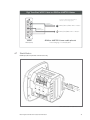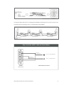
1
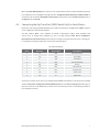
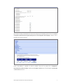
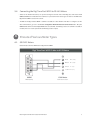
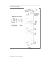
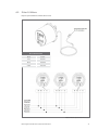
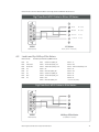
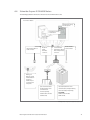
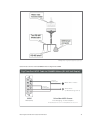
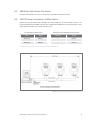
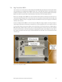
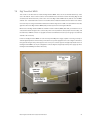
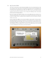
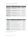
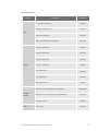
Meter Engineers
Handbook
for Cellular
Communication
Introduction
When Digi began serving
the utility industry, Dire Straits
“Money for Nothing” topped
the Billboard charts, the first
cell phone was hitting the market
(weight: 1.3lbs, talk time: 1hr)
and Ronald Reagan was president.
We’ve come a long way since 1985, but the qualities that we started with—dedicated engineering, responsive tech
support and an industry-leading warranty—are the same qualities that allow us to continue serving the largest
investor owned utilities as well as the smallest rural electric cooperatives.
On the following pages we provide information on connecting common C&I meters with Digi TransPort® 3G and 4G
LTE cellular routers, as well as information on installation, cabling and antennas.
Special thanks are due to Digi customers in meter shops across the world. Thank you for sharing what you’ve
learned as you have used Digi product in the field.
We’ve enjoyed writing this guide and we hope you’ll find it useful. If you notice anything outdated or think of
something to add, please send us an email.
Tony Chun, Cellular Application Engineer, [email protected]
Andrew Lund, Product Marketing Manager, [email protected]
Meter Engineers Handbook for Cellular Communication
1
Table of Contents
Section 1 Cellular Communications for Commercial and Industrial Metering. . . . . . . . . . . . . . . . . . 3
Section 2 Initial Setup and Configuration for
Digi Transport® WR21, WR41 and WR44. . . . . . . . . . . . . . . . . . . . . . . . . . . . . . . . . . . . . . . . . . . 4
2.1 Common Digi TransPort Setup Procedures for all Meter Types . . . . . . . . . . . . . . . . . . . . . . . . . . . . . . . . 4
Section 3 Connecting the Digi Transport to Common Electric Meters. . . . . . . . . . . . . . . . . . . . . . . . . 5
3.1 Common Problems when Connecting to a Digi TransPort via the
Ethernet Cable. . . . . . . . . . . . . . . . . . . . . . . . . . . . . . . . . . . . . . . . . . . . . . . . . . . . . . . . . . . . . . . . . . . . . . . . . . . . . 5
3.2 Connecting the Digi TransPort to Ethernet Capable Meters (All
Meter Types). . . . . . . . . . . . . . . . . . . . . . . . . . . . . . . . . . . . . . . . . . . . . . . . . . . . . . . . . . . . . . . . . . . . . . . . . . . . . . . 5
3.3 Connecting the Digi TransPort (WR21 Model Only) to Serial Meters. . . . . . . . . . . . . . . . . . . . . . . . . . . . 6
3.4 Connecting the Digi TransPort WR21 to RS-485 Meters . . . . . . . . . . . . . . . . . . . . . . . . . . . . . . . . . . . . . . . 8
Section 4 Pinouts of Various Meter Types . . . . . . . . . . . . . . . . . . . . . . . . . . . . . . . . . . . . . . . . . . . . . . . . . . 8
4.1 GE KV2C Meters. . . . . . . . . . . . . . . . . . . . . . . . . . . . . . . . . . . . . . . . . . . . . . . . . . . . . . . . . . . . . . . . . . . . . . . . . 8–9
4.2 Elster A3 Meters. . . . . . . . . . . . . . . . . . . . . . . . . . . . . . . . . . . . . . . . . . . . . . . . . . . . . . . . . . . . . . . . . . . . . . . . . . 10
4.3 Landis and Gyr MAXsys Elite Meters . . . . . . . . . . . . . . . . . . . . . . . . . . . . . . . . . . . . . . . . . . . . . . . . . . . . . . . 11
4.4 Schneider Square D ION8650 Meters . . . . . . . . . . . . . . . . . . . . . . . . . . . . . . . . . . . . . . . . . . . . . . . . . . . 12–13
4.5 ABB/Elster Alpha Power Plus Meters. . . . . . . . . . . . . . . . . . . . . . . . . . . . . . . . . . . . . . . . . . . . . . . . . . . . . . . . 14
4.6 AMETEC Power Instruments JEMStar Meters. . . . . . . . . . . . . . . . . . . . . . . . . . . . . . . . . . . . . . . . . . . . . . . . 14
4.7 Shark Meters. . . . . . . . . . . . . . . . . . . . . . . . . . . . . . . . . . . . . . . . . . . . . . . . . . . . . . . . . . . . . . . . . . . . . . . . . . 15–16
Section 5 Mounting and Power Options for Various Digi TransPort
Types (WR21, WR41, WR44) in Metering Applications. . . . . . . . . . . . . . . . . . . . . . . . . . . . . 17
Section 6 Evaluating Your Signal. . . . . . . . . . . . . . . . . . . . . . . . . . . . . . . . . . . . . . . . . . . . . . . . . . . . . . . . . 18
Section 7 Digi TransPort Model-Specific Mounting Instructions. . . . . . . . . . . . . . . . . . . . . . . . . . . . . 19
7.1 Digi TransPort WR21. . . . . . . . . . . . . . . . . . . . . . . . . . . . . . . . . . . . . . . . . . . . . . . . . . . . . . . . . . . . . . . . . . . . . . . 20
7.2 Digi TransPort WR41. . . . . . . . . . . . . . . . . . . . . . . . . . . . . . . . . . . . . . . . . . . . . . . . . . . . . . . . . . . . . . . . . . . . . . 21
7.3 Digi TransPort WR44. . . . . . . . . . . . . . . . . . . . . . . . . . . . . . . . . . . . . . . . . . . . . . . . . . . . . . . . . . . . . . . . . . . . . . . 22
Product Descriptions and Part Numbers. . . . . . . . . . . . . . . . . . . . . . . . . . . . . . . . . . . . . . . . . . . . . . . . . . . . . 23–24
Meter Engineers Handbook for Cellular Communication
2
1
Cellular Communications for Commercial and
Industrial Metering
Flexible and secure cellular routers connect remote
C&I meters with a utility’s meter data management system
for accurate billing and planning.
The utilities business is challenged from every angle to be increasingly productive and profitable. The very nature
of managing remote equipment in many locations can be difficult and expensive, and maximizing uptime while
reducing costs is often a requirement. Meter shops face a growing set of demands: more accurate and timely
billing, increased support for dispute resolution, measurement of power quality and reactive power, and support
for measuring the cost of power delivery. To meet these demands, metering professionals need a cellular router
that:
• Supports multiple Ethernet and serial devices
• Can be preconfigured for easy installation by field technicians
• Is certified on Sprint, Verizon, AT&T, Rogers and Telus
• Offers the high security features required by NERC/CIP
Digi TransPort® routers fit the bill. They are secure (dynamic routing, VPN and firewall support), carrier-agile
(supporting Sprint, Verizon and AT&T on one platform) and flexible (with Ethernet, RS232/485, GPS, USB and
analog/digital IO). Learn more at www.digi.com/transport.
Digi’s Solutions for the Utility Industry
Problem
Solution
“Under the glass” cellular-enabled meters
can’t be moved to improve reception.
Digi TransPort routers offer several mounting
and antenna options.
Meter shops must support a mix of new and legacy
equipment with diverse protocols and physical interfaces.
Digi TransPort cellular routers have Ethernet and serial
ports, proven compatibility with common MDM systems and
support for DNP and Modbus.
No way to confirm proper communication between a
meter and router.
Digi TransPort routers can be pre-configured to double
check communication and green light
the installation.
Complicated installations require training and
documentation.
Pre-assembled, weatherproof Utility Communication Hub
simplifies installation.
Expensive and complicated to support a piecemeal
solution with products from
many vendors.
Digi offers a single source for all warranty
and support concerning the Utility
Communication Hub.
Meter Engineers Handbook for Cellular Communication
3
2
Initial Setup and Configuration for
Digi Transport® WR21, WR41 and WR44
2.1 Common Digi TransPort Setup Procedures for all Meter Types
PRE-CONFIGURATION OF DIGI TRANSPORT
Required equipment for this configuration:
• Digi TransPort WR21, WR41 or WR44
• Computer or laptop
• Ethernet cable
• SIM and data plan purchased from a carrier (Verizon, ATT, etc.)
CONNECTING TO THE CARRIER
–– Insert the SIM into SIM 1 slot on the front of the Digi TransPort and screw on both WWAN antennas.
–– Connect the Ethernet cable to port 0 of the Digi TransPort (some models only have one Ethernet port).
–– Connect the Ethernet cable to the laptop.
–– Power on the Digi TransPort.
–– Open a browser on the laptop; i.e., Internet Explorer, Firefox, Chrome, etc.
–– In the URL window type 192.168.1.1. The default configuration of the Digi TransPort has the DHCP turned on so
the laptop will be given an IP address automatically. The built in WebUI of the router should now be displayed (see
section 1.2 for common problems if you aren’t able to connect).
–– When the login screen comes up, type in the username and password. The default username and password is
username and password (all lower case). After login you will go immediately to the Home screen.
–– On the menus to the left, just below the Home option, you will see the Wizards option. Click on Wizards and then
choose the Carrier Switching Wizard. Follow the directions in the Wizard and pick whichever carrier you’ve chosen.
• If you are using Verizon there is nothing else to do. It might take 10-15 minutes but the Digi TransPort will self
register and populate its APN.
• If you are using AT&T (and some others) then an APN must be manually entered here: ConfigurationNetwork>Interfaces>Mobile. Click on the button to Use custom APN instead of built-in APN and enter the
APN (Check with your carrier as to what APN your particular SIM uses, some common ones for AT&T are
broadband, INTERNET and i2gold). It may take 10-15 minutes for the Digi TransPort to register.
Meter Engineers Handbook for Cellular Communication
4
3
Connecting the Digi Transport to Common
Electric Meters
3.1
Common Problems when Connecting to a Digi TransPort via
the Ethernet Cable
–– Turn off the Wi-Fi on the laptop before connecting the Ethernet cable to the Digi TransPort. The Wi-Fi DHCP could
also be using the 192.168.1.X network.
–– You may need to release your old IP address in order to acquire a new one from the Digi TransPort. On a Microsoft
Windows system you can do this by going to the command line (Start->Run->cmd) and entering ipconfig /release
followed by ipconfig /renew.
3.2
Connecting the Digi TransPort to Ethernet Capable Meters
(All Meter Types)
–– In the Digi TransPort WebUI go to Configuration-Network > IP Routing/Forwarding > IP Port
Forwarding/Static NAT Mappings. This is where you will define where to redirect the communications from the
head-end server. Note that each meter IP and Port must be known. A typical configuration is below (IP addresses
and Ports may differ depending on how the meter is set up):
–– After entering each rule hit the Add button. When finished hit the Apply button and then click on the Save here
button when it pops up. Hit the Save All button when the new window pops up.
Meter Engineers Handbook for Cellular Communication
5
–– When using Static NAT Mappings the IP and Port on the cellular interface must be enabled. By default only the IP
port is NAT’d. Go here in the WebUI of the Digi TransPort: Configuration-Network>Interfaces>Advanced>PPP 1.
Scroll down to the checked box Enable NAT on this interface and check the circle for IP address and Port. Click on
the Apply button and Save All.
3.3 Connecting the Digi TransPort (WR21 Model Only) to Serial Meters
–– Most meters come equipped with RS-232/485 ports to enable communications. The Digi TransPort WR21 serial port
can be configured for either RS-232 or RS-485.
–– The Digi TransPort WR21 comes defaulted for RS-232 communication (115200 baud, Hardware flow
control, 8,n,1). To change these parameters go here in the Digi TransPort WR21 WebUI: ConfigurationNetwork>Interfaces>Serial>Serial Port 0. Check the user manual for the particular meter you’re connecting too
to see what these settings should be. Here is the pinout of the RS-232 port:
RS-232 Port Pinout
Pin #
Direction
RS-232 DCE
Description
1
Out
DCD
Data Carrier Detect
2
Out
RXD
Receive Data
3
In
TXD
Transmit Data
4
In
DTR
Data Terminal Ready
5
N/A
GND
Ground
6
Out
DSR
Data Set Ready
7
In
RTS
Ready To Send
8
Out
CTS
Clear To Send
9
Out
RI
Ring Indicate
–– The serial port needs to be set up as a ‘Port’ the Digi TransPort WR21 can forward too. To do this go here in the Digi
TransPort WR21 WebUI: Configuration-Network>Network Services. In the ASY 0 Listening Port: window type in
the port you want to use. By default this is port 4000 and it can be left as port 4000. In the following example it’s
been changed to port 2000:
Meter Engineers Handbook for Cellular Communication
6
–– Now redirect incoming communications to this port by using the port forwarding rules. Go here in the WebUI:
Configuration-Network>IP Routing/Forwarding>IP Port Forwarding/Static NAT Mappings. Add the rule to
forward to the serial port as below.
–– Ensure that NAT’ing is applied on both IP address and Port by going here: ConfigurationNetwork>Interfaces>Advanced>PPP 0. Make sure the IP Address and Port circle is checked under the Enable NAT
on this interface check box.
Meter Engineers Handbook for Cellular Communication
7
3.4
Connecting the Digi TransPort WR21 to RS-485 Meters
–– Similar to the RS-232 instructions, set up the Listening Port and the Port Forwarding rules and ensure the IP
Address and Port are enabled for PPP 1 interface. For pinouts from the various types of meters to the DB9 of the
Digi TransPort WR21 see below in section 4.
–– The DB9 of the Digi TransPort WR21 is software selectable for either RS-232 or RS-485. To configure it for RS485 communication, go here in the WebUI: Configuration-Network>Interfaces>Serial>Serial Port 0. Drop the
Advanced tab down and in the Async Mode: box select RS-485. Terminating resistors are software selectable if
needed, there is no need to put external terminating resistors in place.
4
Pinouts of Various Meter Types
4.1
GE KV2C Meters
Cable Pinouts to Connect KV2 Meters to Digi TransPort WR21
Digi TransPort WR21 Cable to KV2 Meters
1
5
4
3
2
1
9
2
Red
R+ (out)
8
3
Black
R- (out)
7
4
Green T- (in)
6
5
Yellow T+ (in)
6
WR21
DB9 (Male)
Meter Engineers Handbook for Cellular Communication
KV2 Meter
RJ11 Connector
8
Terminating resistors are only needed at the last meter if multiple meters are connected. A non-terminating resistor
is needed at the Digi TransPort WR21.
MODBUS Cable Connector Wiring
Modbus Communications Option document. GEH-7282. Pgs. 43, 46
Meter Engineers Handbook for Cellular Communication
9
4.2 Elster A3 Meters
Requires optional RS-485 communications board.
RJ-11 Connections
Black
Receive -
Red
Receive +
Green
Transmit +
Yellow
Transmit -
Modbus Communications Option document. IL42-4009D. Pgs. 2, 3
Meter Engineers Handbook for Cellular Communication
10
Cable Pinouts to Connect Elster A3 Meters to the Digi TransPort WR21 RS-485 Serial Port
Digi TransPort WR21 Cable to Elster A3 Meters
1
5
4
3
2
1
9
2
Red
R+ (out)
8
3
Black
R- (out)
7
4
Green
T- (in)
6
5
Yellow T+ (in)
6
A3 Meter
WR21
RJ11 (6-Pin Female)
DB9 (Male)
4.3 Landis and Gyr MAXsys Elite Meters
Meter Pinouts
RS-232-2,3,4 & RS-485 (J2) DB25 Pinout
Pin 17 CL -
Pin 1NC
Pin 9
Pin 2
TX RS-232-2
Pin 10 *TX RS-232-3/485A_OUT-
Pin 18Gnd
Pin 3
RX RS-232-2
CTS RS-232-3/485A_IN-
Pin 11 *RTS RS-232-3/485A_OUT+
Pin 19 *RTS RS-232-4/485B_OUT+
Pin 4NC
Pin 12NC
Pin 20NC
Pin 5
Pin 25 RX RS-232-3/485A_IN+
Pin 21R13
Pin 6NC
Pin 13 CTS RS-232-4/485B_IN-
Pin 22NC
Pin 7Gnd
Pin 14 *TX RS-232-4/485B_OUT-
Pin 23NC
Pin 8NC
Pin 15Gnd
Pin 24NC
Pin 16 RX RS-232-4/485B_IN+
* Used for RS-485 (2-Wire)
CL +
Digi TransPort WR21 Cable to Elite Meters
5
4
3
2
1
9
11
8
10
7
9
6
25
WR21
DB9 (Male)
Meter Engineers Handbook for Cellular Communication
MAXsys Elite Meter
J2 (DB25 Female)
11
4.4
Schneider Square D ION8650 Meters
The following illustration shows the connection to the communications card.
Back view of ION8650
Communications wiring
on breakout panel
Communications wiring
on switchboard
Ethernet 10/100Base-T:
RJ45 connector.
Modem on
COM2:
RJ11 male
connector.
Serial COMs and
Expanded I/O: Molex
Micro-Fit 24 pin male
connector.
IRIG-B GPS Time
Synchronization.
ANSI Type II
Magnetic Optical
Communications
Coupler on
COM3. This port
is located on the
front panel.
Optical communications
breakout cable for serial
communications.
Optical I/O Expander for serial
communications (and expanded I/O).
Ordered separately.
Serial COMs
COM1: RS-232 or RS-485.
COM4: RS-485.
COM1: RS-232 or RS-485.
COM4: RS-485.
Ordered and shipped separately.
PowerLogic ION8650 – Energy and power quality meter User guide. Pg. 84
Meter Engineers Handbook for Cellular Communication
12
PowerLogic ION8650 – Energy and power quality meter User guide. Pg. 93
Cable Pinouts to Connect Schneider ION8650 Meters to Digi TransPort WR21
Digi TransPort WR21 Cable to ION8650 Meters (RS-485 Half-Duplex)
5
4
3
2
1
9
Connect wires
from WR21 together
8
7
Connect wires
from WR21 together
6
WR21
DB9 (Male)
Black Wire = Data -
White Wire
(or Red if using com 4)
Schneider 8650 Comm
Free Hanging - 2 twisted pairs
White/Black pair are com 1 and Red/Black pair are com 2
Meter Engineers Handbook for Cellular Communication
13
4.5 ABB/Elster Alpha Power Plus Meters
Identical to Elster A3 Meters in section 5.1. Requires optional RS-485 communications board.
4.6
AMETEC Power Instruments JEMStar Meters
Requires the optional RS-485 board. Half Duplex (two wire) RS-485 only. 120 ohm termination resistor is not
required at the Digi TransPort WR21 end of the cable. The Digi TransPort WR21 has an internal termination resistor
that is software selectable. It is necessary at the meter end.
RS-485 Output Connections
Switchboard RS-485 Output Connections
Color
Signal
Terminal
Signal
Wht/Grn/Blu
XMT/RCV -
21
XMT/RCV -
Wht/Grn/Blu
XMT/RCV +
22
XMT/RCV +
For Switchboard style meters, the connections are provided on terminal blocks.
JEMStar Digital Multifunction Electricity Meter User Manual. Pub: 1083-600 Rev S. Pgs. 50, 55
Meter Engineers Handbook for Cellular Communication
14
Digi TransPort WR21 Cable to JEMStar AMETEK Meters
5
4
3
2
1
Use pins if equiped with terminal block,
otherwise use free hanging wires
9
8
7
Connect wires
from WR21 together
21
White/Green/Blue Wire = Data -
22 White/Red/Blue Wire = Data +
6
WR21
DB9 (Male)
4.7
Connect wires
from WR21 together
JEMStar AMETEK Comm cable pinouts
Free Hanging - 2 twisted pairs
Shark Meters
Half-Duplex (two wire) RS-485 communication only
Shark 200 and 200T. Installation and Operation Manual. V1.14. Pg. 5-2
Meter Engineers Handbook for Cellular Communication
15
Shark 200 and 200T. Installation and Operation Manual. V1.14. Pg. 5-3
Hooking up multiple Shark meters to a single Digi TransPort WR21. Terminating resistors are only necessary on the
last Shark meter. No terminating resistor is needed at the Digi TransPort WR21.
Shark 200 and 200T. Installation and Operation Manual. V1.14. Pg. 5-4
Digi TransPort WR21 Cable to Shark Meters
5
4
3
2
1
9
Connect wires
from WR21 together
8
7
Connect wires
from WR21 together
+
+ Pin on Shark Meter
-
- Pin on Shark Meter
6
WR21
Shark Meter Comm
DB9 (Male)
Meter Engineers Handbook for Cellular Communication
16
5
Mounting and Power Options for Various Digi
TransPort Types (WR21, WR41, WR44)
in Metering Applications
COMMON TO ALL DIGI TRANSPORT MODELS
Digi TransPort routers are not designed to be exposed to the weather. They must be installed in enclosures that are
rated for at least IP66. Digi has a ready-made unit called the Utility Communication Hub (part number 70001699)
that comes with a Digi TransPort WR21 pre-mounted inside. It’s already IP66 certified and has the advantages of
battery backup and a multi-port switch if more than one Ethernet connection is needed. It also has a built in power
supply rated for up to 277Vac. Digi also has several integrator partners who specialize in weatherproof housing and
auxiliary power solutions.
Most Digi TransPort models are designed for a wide temperature range (-20° to +75° C typical) so unless you expect
extreme temperatures in your area there is no need to ventilate the enclosure. A few inches of open space in an
enclosure is usually sufficient to dissipate any heat.
If the enclosure you are using is RF transparent (plastic) you may be able to use the antennas that come with the
Digi TransPort. It really depends on how close you are to the carrier towers. It’s important that the antennas be at
least 4 or 5 inches (more is better) from any metal object. Metal has the effect of detuning the antenna. You should
also take care to mount it securely (see options below) and not to get too close to any exposed AC lines.
If you are using a metal enclosure, or need higher gain antennas then what Digi can supply, you’ll need to use
external antennas. Generally the antennas can be mounted directly on the top of the enclosure but it might
sometimes be necessary to mount them remotely (you may need to mount them on a tall poll for instance to get
better visibility to a tower). Care must be taken to keep the coaxial cable length to a bare minimum. Long cables
introduce RF loss that can wipe out any advantages to remotely mounting the antenna. A good rule of thumb is to
keep the coaxial cable at, or less than, 15 feet if you are using RG174 or RG58. Better coaxial cable, like LMR400 for
example, can have longer runs. But shorter is always better.
A NOTE ABOUT LTE
In many 3G HSPA and EVDO networks, routers are frequently deployed and configured with two antennas to
achieve “receive diversity.” (The primary antenna transmits and receives while the secondary antenna is receive
only.) With this configuration, the router is better able to cope with multipath interference that occurs when signals
bounce off obstructions (e.g., buildings, trees or airplanes) and arrive at the antenna out of phase. Two receive
antennas, placed where signals can be best received and combined, can help counteract multipath interference.
Conversely, LTE uses multiple input/multiple output (MIMO) where both antennas transmit and receive. While it is
possible to use one antenna (and operate the device in SISO mode), two antennas are a better choice for optimum
performance. Using one antenna will cause bandwidth to vary based on the RF conditions at the operating site.
Application performance will also suffer, sometimes cutting bandwidth as much as 50 percent. Regardless, best
practices call for using directly attached antennas.
Meter Engineers Handbook for Cellular Communication
17
6
Evaluating Your Signal
In 2G and 3G networks, signal strength was best understood using the received signal strength indicator (RSSI),
measured in dBm. That value alone only provides a measure of the total signal including noise, and, of course,
noise degrades the performance of a cellular connection. For example, a cellular router installed in an electric
substation may pick up a strong cellular signal – but it will still perform poorly due to electromagnetic interference.
That’s why it’s important to understand not only the strength of the signal, but also its quality.
Most 2G/3G CDMA and WCDMA (i.e., UMTS/HSPA) devices also report Ec/Io which is a better indicator of signal
quality. However, this metric is less commonly used and not as well understood as RSSI.
For 3G cellular connections, RSSI and Ec/Io determine signal quality:
RSSI
Signal Strength
Ec/lo
Signal Quality
> -70 dBm
Excellent
0 to -6
Excellent
-70 dBm to -85 dBm
Good
-7 to -10
Good
-86 dBm to -100 dBm
Poor
-11 to -20
Fair to Poor
With 4G LTE, operators can now take advantage of three new metrics to help indicate when the device has received
a “good” LTE signal:
Reference Signal Received Power – RSSP indicates the signal strength and is roughly analogous to RSSI.
Reference Signal Received Quality – RSRQ describes the signal quality and is similar to Ec/Io.
Signal to Interference and Noise Ratio – SINR (also called SNR) indicates the throughput capacity of the
channel. As the name implies, SINR is the strength of the signal divided by the strength of any interference.
These parameters may vary depending on the technology being used. The following table describes the RF
conditions that each value range represents.
Meter Engineers Handbook for Cellular Communication
18
RF Conditions
RSRP (dBm)
RSRQ (dB)
SINR (dB)
Excellent
>=-80
>=10
>=20
Good
-80 to -90
-10 to -15
13 to 20
Mid Cell
-90 to -100
-15 to -20
0 to 13
Cell Edge
>=-100
>=-20
>=0
For example, a 4G LTE modem might report an RSSI of -68 dBm, but:
RSRP = -102 dBm
RSRQ = -16 dB
SNR = -1.8 dB
In this case, the signal quality is actually very poor. This could be due to the device being some distance away
from the LTE transmitter. It’s also possible that something is interfering with the signal, such as a building or other
obstructions between the device and the tower.
Ultimately, poor signal quality equals poor performance due to issues such as retransmissions. Not only does poor
signal quality degrade performance, it also adds cost to monthly data plans.
7
Digi TransPort Model-Specific
Mounting Instructions
If you expect to mount the Digi TransPort router inside your own enclosure, or inside the meter cabinet itself, then
use the mounting options described on the following pages.
Meter Engineers Handbook for Cellular Communication
19
7.1
Digi TransPort WR21
Two screw holes are on the bottom to mount the Digi TransPort WR21. Digi separately sells a bracket (Part number
76000775) that fits over the Digi TransPort WR21 and has “ears” or tabs that make it easier to mount. Note that to
install this bracket the four rubber “feet” must be removed. They are easily pried off with a flathead screw driver.
Digi also has a SIM cover (part number 76000787) that prevents anyone from removing the SIM card.
Dimensions of the Digi TransPort WR21 are 100mm x 131mm x 32mm (L x W x H). Note that you should choose an
enclosure that allows enough room to connect the power connector, Ethernet cables (and/or the serial cable), and
the antennas (or SMA RF connector on a pigtail coax cable to a bulkhead connector if you are going to use antennas
external to the enclosure).
Power for the Digi TransPort WR21 can come from any 9-30V DC power supply capable of sourcing 1.5 amps. In
extreme high temperature environments you should choose a power supply that can source a higher current do
to the typical de-rating of most power supplies. There are two types of connectors that come on a Digi TransPort
WR21 depending on which model you order. There is a 2.1mm locking barrel connector type and a more industrial
Phoenix connector that has screw down leads. Digi can supply high temperature power supplies for either option.
Part number 76000752 for the barrel type and 76000736 with bare leads that can be used with the Phoenix
connector type.
Bottom view of a Digi TransPort WR21.
Meter Engineers Handbook for Cellular Communication
20
7.2
Digi TransPort WR41
Two screws are on the bottom to mount the Digi TransPort WR41. These are the screws that hold the top of the
case to the bottom. These screws need to be removed and the holes can then be used for mounting. Digi also has
a bracket (Part number 76000775, same as the one for the Digi TransPort WR21 above) that fits over the WR41
and has ‘ears’ or tabs that make it easier to mount. Note that to install this bracket the four rubber ‘feet’ must be
removed. They are easily pried off with a flathead screw driver. Digi also has a SIM cover (Part number 76000787,
again the same as the Digi TransPort WR21) that prevents anyone from removing the SIM card.
Dimensions of the Digi TransPort WR41 are 120mm x 173mm x 32mm (LxWxH). Note that you should choose an
enclosure that allows enough room to connect the power connector, Ethernet cables (and/or the serial cable), and
the antennas (or SMA RF connector on a pigtail coax cable to a bulkhead connector if you are going to use antennas
external to the enclosure).
Power for the Digi TransPort WR41 can come from any 8-48V DC power supply capable of sourcing 1.5 amps. In
extreme high temperature environments you should choose a power supply that can source a higher current do to
the typical de-rating of most power supplies. There is only one connector type for the high temperature version of
the Digi TransPort WR41. It’s a 4 pin locking Molex connector. Digi has a high temperature power supply specific to
the Digi TransPort WR41 (part number 76000790).
Bottom view of a Digi TransPort WR41.
Meter Engineers Handbook for Cellular Communication
21
7.3
Digi TransPort WR44
Two screws are on the bottom to mount the Digi TransPort WR44. These are the screws that hold the top of the
case to the bottom. These screws need to be removed and the holes can then be used for mounting. Digi also has
a bracket (part number 76000778) that fits over the Digi TransPort WR44 and has “ears” or tabs that make it easier
to mount. Note that to install this bracket the four rubber “feet” must be removed. They are easily pried off with
a flathead screw driver. Digi also has a SIM cover specific to the Digi TransPort WR44 (part number 76000785) that
prevents anyone from removing the SIM card.
Dimensions of the Digi TransPort WR44 are 145mm x 210mm x 40mm (LxWxH). Note that you should choose an
enclosure that allows enough room to connect the power connector, Ethernet cables (and/or the serial cable), and
the antennas (or SMA RF connector on a pigtail coax cable to a bulkhead connector if you are going to use antennas
external to the enclosure).
Power for the Digi TransPort WR44 can come from any 9-36V DC power supply capable of sourcing 1.5 amps. In
extreme high temperature environments you should choose a power supply that can source a higher current do
to the typical de-rating of most power supplies. There is only one connector type for the high temperature version
of the Digi TransPort WR44. It’s a 4-pin locking Molex connector. Digi has a DC power cord specific to the Digi
TransPort WR44 (part number 76000774) that can be connected to a power supply. A typical “good” power supply
is one similar to BEC (Bobbintron Electrical Corp.) part number AP0181-18U.
Bottom view of a Digi TransPort WR44.
Meter Engineers Handbook for Cellular Communication
22
PRODUCT DESCRIPTIONS AND PART NUMBERS*
Digi TransPort® 3G/4G LTE Cellular Routers (Sample list)
Product
Description
Part Number
Digi TransPort WR21
4G LTE, 2 Ethernet, 1 DB-9 RS-232/422/485, Enterprise VPN,
Extended Temp AC Power Supply
WR21-L52A-DE1-TH
Digi TransPort WR41
4G LTE, 2 Ethernet, 1 DB-25 RS-232/422/485, Enterprise VPN,
Extended Temp AC Power Supply
WR41-L5S1-NE1-XH
Digi TransPort WR44
4G LTE, 4 Ethernet, 1 DB-25 RS-232,
Enterprise VPN, Extended Temp AC Power Supply
WR44-L5S1-CE1-XH
Digi TransPort WR44R
(Rugged)
4G LTE, 4 Ethernet, 1 DB-25 RS-232/422/485, Enterprise VPN,
Extended Temp AC Power Supply
WR44-L5S1-CE1-RH
Accessories
Product
Description
Cellular, Magnet Mount, Dual Band, 4.0 dBi, 14’ cable
Part Number
DC-ANT-DBHG
Cellular, Direct Mount, Penta Band, 3.2 dBi
76000793
Cellular, Surface/Through-Hole Mount, Quad Band, 3.15 dBi
76000847
Cellular, Surface/Through-Hole Mount, Quad Band, 0 dBi
76000846
L-Shaped Wall-Mount, 16.5mm Hole. Compatibility: 7600846
76000850
Antenna
Antenna
Mounting Bracket
* Digi has many different router options available; please see www.digi.com and
contact your Digi sales representative for more information.
Meter Engineers Handbook for Cellular Communication
23
Accessories (cont.)
Product
Description
Part Number
Locking Barrel to Bare Wire, 4’
76000732
SMA Male to SMA Female, 5m
76000830
DB9 Female to DB9 Male, 6’
76000858
DB9 Female to DB25 Male, 6’, Straight-Thru
76000871
SMA Female to SMA Male
76000837
TNC Female to TNC Male
76000836
SMA Male to TNC Female
76000838
SMA Female to TNC Male
76000839
RJ45 to DB9 Female, 6’
76000855
RJ45 to DB25 Male, 6’
76000856
RJ45 to DB25 Female, 6’
76000857
Cable
Adapter
Wall-Mount, Compatibility: Digi Connect® WAN Routers
Mounting
Bracket
Other
DC-BKT-CWAN
Wall-Mount, Compatibility: Digi TransPort WR41 and WR21
76000775
1U Rack-Mount Shelf
76000840
SIM Card Cover
76000787
Meter Engineers Handbook for Cellular Communication
24
While every reasonable effort has been made to ensure that this information is accurate, complete and up-to-date, all information is provided “AS IS” without warranty of any kind. We disclaim
liability for any reliance on this information. All registered trademarks or trademarks are property of their respective owners.
Contact a Digi expert and get started today
PH: 877-912-3444
www.digi.com
Digi International
Worldwide HQ
11001 Bren Road East
Minnetonka, MN 55343
Digi International - France
+33-1-55-61-98-98
Digi International - Japan
+81-3-5428-0261
Digi International - Singapore
+65-6213-5380
Digi International - China
+86-21-5049-2199
/digi.international
@DigiDotCom
/digi-international
© Copyright 2014 Digi International Inc. All rights reserved. 10/15 91002986