1
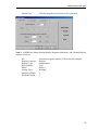
JEMSTAR
Digital Multifunction
Electricity Meter
Application Notes
Publication 1083-608
Rev. A
May 2002
AMETEK Power Instruments
255 N. Union Street
Rochester, New York 14605
Tel: (800) 881-4156
Fax: (585) 238-4945
Web: www.rochester.com
Important Safety Notice
Installation, operation, and maintenance of this product can present potentially hazardous
conditions if safety procedures are not followed. To ensure that this product is used safely,
it is important that you:
• Review, understand, and observe all safety notices and recommendations within
this manual.
• Review your company safety procedures for meter installation and service.
DANGER!
Hazardous voltages are present during normal servicing of this device that can cause
severe injury or death. These voltages are present throughout the utility’s potential
transformer (PT) and current transformer (CT) circuits, and the meter’s connection
terminals. Only qualified, properly trained personnel should perform installation and
servicing on this equipment.
© November, 2000 AMETEK Inc., all rights reserved.
Scientific Columbus is a trademark of AMETEK, Inc.
JEM is a registered trademark of AMETEK, Inc.
MicroJoule II is a registered trademark of AMETEK, Inc.
SC-30 is a registered trademark of AMETEK, Inc.
JEMStar, JEMWare, JEMRead are trademarks of AMETEK, Inc.
MV-90 is a trademark of Itron Energy Information Systems, Inc.
Windows is a trademark of Microsoft Corp.
MODBUS is a trademark of Schneider Systems, Inc.
Table of Contents
Application Notes ............................................................................................................ 1
Introduction ........................................................................................................................... 1
Transmission Line Loss Calculation ................................................................................. 2
JEMStar Transformer and Line Loss Compensation Formulae and Technical Description
........................................................................................................................................... 2
Notes on BPR (Billing Period Reset) .............................................................................. 14
JEMStar Analog Output Verification .............................................................................. 14
External Control of Load Profile Recording ................................................................... 19
Troubleshooting Tips....................................................................................................... 21
General Meter Usage ................................................................................................... 21
JEMWare Software...................................................................................................... 21
JEMRead Software ...................................................................................................... 22
JEMStar Application Notes
INTRODUCTION
The JEMStar meter is a very user-friendly meter, with most features and operating
functions being self-explanatory. Once you become familiar with the basic operation of
the front panel pushbuttons and the simple Windows™ software menus, you can read,
configure and create reports from the data collected by the meter. Hardware and software
instruction manuals, and a Windows Help system are included to assist you with detailed
explanations of the extensive operating features of JEMStar.
This document is intended to assist the advanced user by providing some insight into the
application of JEMStar’s features. The topics and suggestions contained herein represent a
collection of user’s requests and experiences with the meter. We hope that this will
provide a forum to expand your knowledge, and at the same time, keep us in touch with
your metering needs. We welcome your thoughts and requests, and we would be
interested in discussing the future of utility metering with you. Our toll-free 800 number,
listed on the cover, is available for your use.
1
JEMStar Multifunction Electricity Meter
TRANSMISSION LINE LOSS CALCULATION
It is possible to perform line loss compensation for line losses on the primary side of the
main transformer. You should be familiar with JEMWare operation and the use of the
Transformer Loss Compensation (TLC) feature. If not, review this section in the
JEMWare manual (publication 1083-602) before proceeding.
Presently, the line resistance entered in the JEMWare TLC window is applied to the
primary side of the PT and CT (the secondary side of the main transformer). To perform
line loss compensation on the primary side of the main transformer, do the following.
In the JEMWare TLC window, enter the primary line resistance divided by the square of
the transformer turns ratio, where the turns ratio is given as primary turns/secondary turns.
R = Primary Line Resistance / (turns ratio)2
Where:
R = resistance to be entered into JEMWare TLC screen in ohms
Primary Line Resistance = primary side line resistance in ohms
Turns ratio = main transformer turns ratio = primary turns/secondary turns
JEMSTAR TRANSFORMER AND LINE LOSS
COMPENSATION FORMULAE AND TECHNICAL
DESCRIPTION
The following describes the methods and equations used by the JEMStar meter and
JEMWare software to implement transformer and line loss compensation. An actual
example using a Form 9 meter is illustrated at the end of the discussion.
A. DATA REQUIRED FOR TRANSFORMER AND LINE LOSS COMPUTATION
TRANSFORMER AND LINE DATA
JEMWare allows single phase or multi-phase computation of TLC. For the
purposes of this example, each value is a transformer per phase value. As
described in JEMWare manual 1083-602, the following parameters must be entered
into the Loss Compensation window (item 7 is only required if computing Line
Loss).
2
1. RATED VOLT AMPS
VAT
2. RATED VOLTAGE
VT
3. FE LOSS @ NO LOAD
NLW
JEMStar Application Notes
4. CU LOSS @ FULL LOAD
FLW
5. EXCITING CURRENT
%EC
6. IMPEDANCE
%I
7. LINE RESISTANCE
RL
NOTES:
1.
Form 6, 8, 9 & Form 5 (3 wire delta and 3 wire Y):
In the case of three-phase transformer and line loss data, divide the total
three phase data values for items 1, 3, 4, and 7 by three to enter transformer
data on a per-phase basis. Data values for items 2, 5, and 6 remain the same
whether using three-phase total or individual phase calculations.
2.
Form 5 (open delta and network):
In the case of two-phase transformer and line loss data, divide total two
phase data values for items 1, 3, 4, and 7 by two to enter transformer data
on a per phase (phases A and C only) basis. Data values for items 2, 5, and
6 remain the same whether using three-phase total or individual phase
calculations.
3.
Iron losses are related to the transformer phase voltage.
Copper losses are related to the transformer phase current.
METER AND INSTRUMENT TRANSFORMER DATA
The following parameters are used in the computation of TLC coefficients.
PT RATIO
PTRATIO
CT RATIO
CTRATIO
NOMINAL METER VOLTAGE
METER TEST CURRENT
IMETER
(from JEMWare Primary Config screen)
(from JEMWare Primary Config screen)
VMETER (from JEMWare Primary Config
screen)
(from JEMWare Loss Compensation screen)
3
JEMStar Multifunction Electricity Meter
B. TLC EQUATIONS
JEMStar calculates loss watts and VARs based on the following formulas:
IRON LOSS WATTS = KWFE x V2
COPPER LOSS WATTS = KWCU x I2
IRON LOSS VARS = KVFE x V4
COPPER LOSS VARS = KVCU x I2
Where “V” is the voltage across and “I” is the current through each phase of the
transformer.
KWFE, KWCU, KVFE, KVCU are coefficients calculated by JEMWare and downloaded
to the JEMStar meter during configuration. Each meter element (per phase) watt
and VAR reading is compensated individually. NOTE: The values for these
coefficients are displayed on the JEMWare CONSTANTS page of the Loss
Compensation screen, and are scaled for the JEMWare internal circuitry and
mathematical requirements. The values calculated in this example are not scaled
and will not be equivalent to those displayed by JEMWare.
C. JEMWare CALCULATION OF TLC COEFFICIENTS
First, we must define a few terms used in the following description of TLC
coefficient calculation.
Transformer phase: refers in this description to an individual leg of a multiphase transformer or a single transformer of a multi-phase bank.
Meter element: refers to an internal meter input consisting of a current and
voltage input pair. It is important to note for purposes of TLC that for certain
meter forms, there is not a direct correlation between transformer phases and
meter elements.
Forms 6, and 9: Three transformer phases A, B, C measured with three
internal meter elements A, B, C (Form 6 is a 2 ½ element meter, but the
missing phase voltage is reconstructed digitally.). The meter elements directly
measure the transformer phase voltages and currents.
Form 8: Three transformer phases A, B, C measured with three internal meter
elements A, B, C. However, because of the delta configuration, the meter
elements measure transformer line currents (not phase currents) and because the
4
JEMStar Application Notes
voltages are measured with respect to neutral, none of the meter voltages
correspond directly to the voltage across the transformer secondary windings.
Form 5 (3 wire delta): Three transformer phases A, B, C measured with two
internal meter elements A and C. The meter elements measure the phase
voltages and the line currents (not phase currents).
Form 5 (3 wire Y): Three transformer phases A , B, C measured with two
internal meter elements A and C. The meter elements measure the phase
currents and the line-line voltage (not phase voltages).
Form 5 (open delta and network): Two transformer phases A and C
measured with two internal meter elements A and C. The meter elements
directly measure the transformer phase voltages and currents.
The JEMStar meter performs loss compensation at the individual element level.
JEMStar calculates and compensates the watts and VAR measurements for each
meter element individually, so each meter element has its own TLC coefficients.
The individual element compensated watt and VAR measurements are then
summed to form the total system measurement. In all cases except Form 8, the
TLC coefficients for each of the meter elements are identical in value.
The general calculation steps are as follows:
1. JEMWare calculates the transformer watts and VAR losses on a per
transformer phase basis when the meter is running at its nominal voltage
and test current.
2. The program sums the transformer per phase losses resulting in the total
system losses.
3. The program apportions the total system losses among the meter elements
and calculates TLC coefficients for each internal meter element.
Forms 6 and 9: 1/3 of the system losses are apportioned to each of the 3
meter elements.
Form 5: ½ of the system losses are apportioned to each of the 2 meter
elements.
Form 8: 1/3 of the system copper watt and VAR losses are apportioned to
each of the 3 internal meter elements. Approximately 73% of the system
iron watt and VAR losses are apportioned to element A, with the remaining
iron losses split evenly between elements B and C. This compensates for
the fact that phase A measures a voltage that is 208/120 higher than phases
5
JEMStar Multifunction Electricity Meter
B and C, and for the fact that none of the elements directly measure the
line-to-line transformer voltage.
4. When the TLC feature is “Enabled“ in the JEMWare configuration, these
losses will be added to or subtracted from the JEMStar per phase watt and
VAR readings (Adding or subtracting depends on the configuration
settings). The total 3 phase system losses are simply the sum of the three
per phase losses and are added to or subtracted from the polyphase watt and
VAR reading.
6
JEMStar Application Notes
D. TYPICAL EXAMPLE CALCULATIONS
The following equations illustrate the TLC coefficient calculations for a FORM 9
meter:
a. FE WATTS LOSS (KWFE)
Transformer iron watts loss when meter is running at nominal voltage:
(calculated for each of 3 transformer phases)
LWFEphase = (VMETER x PTRATIO / VT)2 x NLW
Percent Loss: (calculated for each of 3 transformer phases)
%LWFEphase = 100 x LWFEphase / (VMETER x PTRATIO x IMETER x
CTRATIO)
Sum the LWFEphase results and apportion 1/3 of the system losses
(LWFEavg) to each of the 3 meter elements.
Calculate TLC coefficient: (calculated for each of 3 meter elements)
KWFE = LWFEavg / (VMETER x PTRATIO)2
b. CU WATTS LOSS (KWCU)
Calculate transformer test current:
IT = VAT / VT
Transformer copper watts loss when meter is running at nominal (test)
current: (calculated for each of 3 transformer phases)
Transformer LWCUTXphase = (IMETER x CTRATIO / IT)2 x FLW
Line watts loss when meter is running at nominal (test) current:
(calculated for each of 3 transformer phases)
LWCULINEphase = (IMETER x CTRATIO)2 x RL
Total transformer and line losses: (calculated for each of 3 transformer
phases)
7
JEMStar Multifunction Electricity Meter
LWCUphase = LWCUTXphase + LWCULINEphase
Percent Loss: (calculated for each of 3 transformer phases)
%LWCUphase = 100 x LWCUphase / (VMETER x PTRATIO x IMETER x
CTRATIO)
Sum the LWCUphase results and apportion 1/3 of the system losses
(LWCUavg) to each of the 3 meter elements.
Calculate TLC coefficient: (calculated for each of 3 meter elements)
KWCU = LWCUavg / (IMETER x CTRATIO)2
c. FE VARS LOSS (KVFE)
Transformer test VA losses. (calculated for each of 3 transformer phases)
NLVAphase = (%EC x VAT) / 100
Transformer test VAR losses. (calculated for each of 3 transformer phases)
NLVARphase = sqrt(NLVAphase2 – NLW2)
Transformer iron VARs loss when meter is running at nominal voltage:
(calculated for each of 3 transformer phases)
LVFEphase = (VMETER x PTRATIO / VT)4 x NLVARphase
Percent Loss: (calculated for each of 3 transformer phases)
%LVFEphase = 100 x LVFEphase / (VMETER x PTRATIO x IMETER x
CTRATIO)
Sum the LVFEphase results and apportion 1/3 of the system losses (LVFEavg)
to each of the 3 meter elements.
Calculate TLC coefficient: (calculated for each of 3 meter elements)
KVFE = LVFEavg / (VMETER x PTRATIO)4
d. CU VARS LOSS (KVCU)
8
JEMStar Application Notes
Transformer test VA losses. (calculated for each of 3 transformer phases)
FLVAphase = (%I x VAT) / 100
Transformer test VAR losses. (calculated for each of 3 transformer phases)
FLVARphase = sqrt(FLVAphase2 – FLW2)
Transformer copper VARs loss when meter is running at nominal (test)
current: (calculated for each of 3 transformer phases)
LVCUphase = (IMETER x CTRATIO / IT)2 x FLVARphase
Percent Loss: (calculated for each of 3 transformer phases)
%LVCUphase = 100 x LVCUphase / (VMETER x PTRATIO x IMETER x
CTRATIO)
Sum the LVCUphase results and apportion 1/3 of the system losses
(LVCUavg) to each of the 3 meter elements.
Calculate TLC coefficient: (calculated for each of 3 meter elements)
KVCU= LVCUavg / (IMETER x CTRATIO)2
e. NUMERICAL EXAMPLE (Form 9)
PER PHASE TRANSFORMER AND LINE LOSS DATA
Phase A
Phase B
Phase C
RATED VOLT AMPS
VAT
9,000,000
9,000,000
9,000,000
RATED VOLTAGE
VT
7967
7967
7967
FE LOSS @ NO LOAD
NLW 7961.3
7961.3
7961.3
CU LOSS @ FULL LOAD FLW 24,945.7
24,945.7
24,945.7
EXCITING CURRENT
%EC 0.353
0.353
0.353
IMPEDANCE
%I
14.49
14.49
14.49
0.05
0.05
0.05
LINE RESISTANCE (ohms) RL
9
JEMStar Multifunction Electricity Meter
METER AND INSTRUMENT TRANSFORMER DATA
PT RATIO
PTRATIO
66:1
CT RATIO
CTRATIO
200:1
NOMINAL METER VOLTAGE
VMETER
120 volts
METER TEST CURRENT
IMETER
10 amps
FE WATTS LOSS (KWFE)
Transformer iron watts loss when meter is running at nominal voltage:
(calculated for each of 3 transformer phases)
LWFEphase = (120 x 66 / 7967)2 x 7961.3 = 7867.6 for each phase
Percent Loss: (calculated for each of 3 transformer phases)
%LWFEphase = 100 x 7867.6 / (120 x 66 x 10 x 200) = 0.05% for
each phase
Sum the LWFEphase results and apportion 1/3 of the system losses
(LWFEavg) to each of the 3 meter elements.
LWFEavg = (7867.6 + 7867.6 + 7867.6) / 3 = 7867.6
Calculate TLC coefficient: (calculated for each of 3 meter elements)
KWFE = 7867.6 / (120 x 66)2 = 0.00012543 for each meter element
CU WATTS LOSS (KWCU)
Calculate transformer test current:
IT = 9,000,000 / 7967 = 1129.66
Transformer copper watts loss when meter is running at nominal (test)
current: (calculated for each of 3 transformer phases)
10
JEMStar Application Notes
Transformer LWCUTXphase = (10 x 200 / 1129.66)2 x 24,945.7 =
78,191.6 for each phase
Line watts loss when meter is running at nominal (test) current:
(calculated for each of 3 transformer phases)
LWCULINEphase = (10 x 200)2 x 0.05 = 200,000 for each phase
Total transformer and line losses: (calculated for each of 3 transformer
phases)
LWCUphase = 78,191.6 + 2,000,000 = 278,191.6 for each phase
Percent Loss: (calculated for each of 3 transformer phases)
%LWCUphase = 100 x 278,191.6 / (120 x 66 x 10 x 200) = 1.76%
for each phase
Sum the LWCUphase results and apportion 1/3 of the system losses
(LWCUavg) to each of the 3 meter elements.
LWCUavg = (278,191.6 + 278,191.6 + 278,191.6 0 / 3 = 278,191.6
Calculate TLC coefficient: (calculated for each of 3 meter elements)
KWCU = 278,191.6 / (10 x 200)2 = 0.06955 for each meter element
FE VARS LOSS (KVFE)
Transformer test VA losses. (calculated for each of 3 transformer phases)
NLVAphase = (0.353 x 9,000,000) / 100 = 31,770 for each phase
Transformer test VAR losses. (calculated for each of 3 transformer phases)
NLVARphase = sqrt(31,770 2 – 7961.32) = 30,756.3 for each phase
Transformer iron VARs loss when meter is running at nominal voltage:
(calculated for each of 3 transformer phases)
LVFEphase = (120 x 66 / 7967)4 x 30,756.3 = 30,036.9 for each phase
Percent Loss: (calculated for each of 3 transformer phases)
11
JEMStar Multifunction Electricity Meter
%LVFEphase = 100 x 30,036.9 / (120 x 66 x 10 x 200) = 0.19% for
each phase
Sum the LVFEphase results and apportion 1/3 of the system losses (LVFEavg)
to each of the 3 meter elements.
LVFEavg = (30,036.9 + 30,036.9 + 30,036.9) / 3 = 30,036.9
Calculate TLC coefficient: (calculated for each of 3 meter elements)
KVFE = 30,036.9 / (120 x 66)4 = 7.634 x 10⁻¹² for each meter element
CU VARS LOSS (KVCU)
Transformer test VA losses. (calculated for each of 3 transformer phases)
FLVAphase = (14.49 x 9,000,000) / 100 = 1,304,100 for each phase
Transformer test VAR losses. (calculated for each of 3 transformer phases)
phase
FLVARphase = sqrt(1,304,1002 – 24,945.72) = 1,303,861 for each
Transformer copper VARs loss when meter is running at nominal (test)
current: (calculated for each of 3 transformer phases)
LVCUphase = (10 x 200 / 1129.66)2 x 1,303,861 = 4,086,917 for each
phase
Percent Loss: (calculated for each of 3 transformer phases)
%LVCUphase = 100 x 4,086,917 / (120 x 66 x 10 x 200) = 25.80%
for each phase
Sum the LVCUphase results and apportion 1/3 of the system losses
(LVCUavg) to each of the 3 meter elements.
LVCUavg = (4,086,917 + 4,086,917 + 4,086,917) / 3 = 4,086,917
Calculate TLC coefficient: (calculated for each of 3 meter elements)
KVCU= 4,086,917 / (10 x 200)2 = 1.02173 for each meter element
12
JEMStar Application Notes
TLC COEFFICIENT SUMMARY
For each Form 9 meter element A, B, and C:
KWFE = 0.00012543
KWCU = 0.06955
KVFE = 7.634 x 10⁻¹²
KVCU = 1.02173
JEMSTAR CALCULATION OF LOSS WATTS AND VARS
Equations for each meter element:
IRON LOSS WATTS = KWFE x V2
COPPER LOSS WATTS = KWCU x I2
IRON LOSS VARS = KVFE x V4
COPPER LOSS VARS = KVCU x I2
Example: If the PT and CT secondaries for each phase are 125 volts and 5
amps respectively.
Scale by PT and CT ratios (done within JEMSTAR)
V = 125 x 66 = 8250 volts
I = 5 x 200 = 1000 amps
Calculate losses for each element
IRON LOSS WATTS = 0.00012543 x 82502 = 8537 watts
COPPER LOSS WATTS = 0.06955 x 10002 = 69,550 watts
IRON LOSS VARS = 7.634 x 10-12 x 82504 = 35,365 VARs
COPPER LOSS VARS = 1.02173 x 10002 = 1,021,730 VARs
13
JEMStar Multifunction Electricity Meter
NOTES ON BPR (BILLING PERIOD RESET)
CAUTION
Data can be lost if it is not downloaded and saved prior to performing a BPR command.
The BPR function is used to clear the storage registers in a JEMStar meter. This operation
can be performed manually from the meter’s front panel user interface, or via JEMRead or
JEMWare software commands. In addition, the user can program an Automatic Schedule
in JEMRead to perform a BPR as a regular occurrence. Make sure that your data has been
saved before a BPR is performed.
JEMSTAR ANALOG OUTPUT VERIFICATION
JEMStar can include an optional feature that consists of three analog output channels. All
three channels are defined at the time of manufacture for either 0-1 mA or 4-20 mA
outputs. Each of the output channels can be configured to represent any instantaneous
quantity measured by the meter (watts, VARs, volts, amps, etc.). This procedure uses
Volts as the test input because it is the simplest quantity to regulate precisely.
Re-calibration of analog outputs must be done at the factory only. However, the user can
verify the accuracy of the outputs by following this procedure. If a problem is found,
please contact AMETEK’s technical support group.
Test Setup
The meter under test should be installed in a test fixture so that the input voltage can be
adjusted during the test. In addition, the outer globe must be removed to allow access to
the front panel pushbuttons, and the Security keys must be installed (See the Maintenance
section of User Manual 1083-600 for this procedure). You will need the following:
• Stable AC voltage source capable of 80 to 120 Vrms at 10VA
• 1K ohm resistor, +/- 0.01% (if testing a meter with 0-1mA outputs)
• 250 ohm resistor, +/- 0.01% (if testing a meter with 4-20mA outputs)
Step 1: Using JEMWare (Meter Settings/Analog Outputs menu), configure all three analog
outputs for the following:
Measured Quantity:
Maximum:
Minimum:
Phase:
14
Volts
120
80
A
JEMStar Application Notes
Output Type:
Click the range that was factory set for your meter
Step 2: In JEMWare (Meter Settings/Display Registers/Add menu), add a Normal display
register as follows:
ID:
Register Category:
Register Type:
Base Quantity:
Phase:
Storage Type:
Number of Digits:
Decimal Position:
Any unused register number (25 shown in the example)
Register
Instantaneous
Volts
Phase A
Working
5
2
15
JEMStar Multifunction Electricity Meter
Step 3: Download this configuration to the meter to be tested. Refer to the JEMWare
instruction manual 1083-602 for further details about downloading new configurations.
Step 4: Connect a stable AC voltage source to Phase A volts. Refer to the connection
diagrams in the JEMStar User Manual 1083-600 for your meter Form. Use a voltage
source capable of 80 to 120 volts, with a minimum 10VA. For a switchboard meter, apply
power to Aux. Power as well.
16
JEMStar Application Notes
Step 5: Connect a load resistor to the meter’s analog outputs. For the S-Base and A-Base
meter styles, JEMStar analog output connections are provided via a 3-foot multi-conductor
cable. The wire colors are as follows.
S- & A-Base Analog Output Connections
Color
Signal
Wht/Red/Brn
Aout 1 Wht/Red/Grn
Aout 1 +
Wht/Org/Brn
Aout 2 Wht/Org/Grn
Aout 2 +
Wht/Blk
Aout 3 Wht/Gry
Aout 3 +
For Switchboard style meters, the connections are provided on rear-mounted terminal
blocks.
Switchboard Analog Output Connections
Terminal
Signal
8
Aout 1 7
Aout 1 +
6
Aout 2 5
Aout 2 +
4
Aout 3 3
Aout 3 +
Depending upon your meter’s output range, connect a load resistor to Aout 1 as follows:
0-1 mA Outputs
+
Aout 1
0 - 1 mA Output
Connection
4-20 mA Outputs
+
1K +/0.01%
Aout 1
-
-
24Vdc
External +
Source
250 ohm, +/0.01%
4 - 20 mA Output
Connection
17
JEMStar Multifunction Electricity Meter
Step 6: Apply 80 volts to the Phase A meter terminals. Repeatedly press the front panel
“READ” pushbutton to scroll to the display register you assigned for Phase A volts in Step
2, and then press “SET” to hold the display at this register. Adjust the source voltage to
read 80.00 +/- 0.02 volts on the LCD display. Measure the output voltage across the load
resistor, and verify that the analog output is as follows:
Range
Reading
0-1mA
0.00 V, +/- 0.001V (+/- 0.1%)
4-20mA
1.00 V, +/- 0.004V (+/- 0.1%)
Step 7: Increase the source voltage to read 120.00 +/- 0.02 volts on the LCD display.
Measure the output voltage across the load resistor, and verify that the analog output is as
follows:
Range
Reading
0-1mA
1.00 V, +/- 0.001V (+/- 0.1%)
4-20mA
5.00 V, +/- 0.004V (+/- 0.1%)
Repeat Steps 5, 6, and 7 for the other two analog outputs at Aout 2, and Aout 3.
18
JEMStar Application Notes
EXTERNAL CONTROL OF LOAD PROFILE RECORDING
JEMStar users have requested a method to distinguish Load Profile data that was collected
during externally recognized, asynchronous periods. In other words, users want to be able
to tell if energy recorded by the meter was consumed while some externally controlled
period, such as a generator shutdown, was in effect.
To date, users have been able to perform this function with register data by using the TOU
Rate Override input. The user configures a Watthour register associated with the TOU
Override rate, and then applies a signal to the TOU Rate Override contact input when the
external condition is present. This is sufficient in some cases, but some users need Load
Profile data that is segregated in the same way.
The solution is to configure Load Profile channels to record only when the TOU Rate
Override input is active. Using the TOU Rate Override input to mark the external
condition allows both registers and Load Profile to collect the same data, which can be
compared later.
JEMWare can be used to configure any Load Profile channel to record when the TOU Rate
Override contact input is ON.
Note: The TOU Rate Override input does not affect interval timing in any way. It will
only gate the collection of measurements in configured Load Profile channels.
Load Profile channels configured to record only during TOU Rate Override are not
associated with a given TOU rate. For example: If the meter is configured to use Rate C as
the TOU Override rate, and Rate C also appears in the normal TOU schedule, the selected
Load Profile channels record only while the TOU Rate Override input is on.
Average Instantaneous Load Profile channels that are configured for TOU Rate Override
are averaged over the period that the TOU Rate Override input is on. For example, with a
constant 1000 watts applied to the meter and an Average Instantaneous Watt load profile
channel, if the TOU Rate Override input is active for one half of an interval the final value
recorded in that interval will be 1000 watts, not 500 watts. If the TOU Rate Override input
stays off for the entire interval, the channel will record 0. (An exception to this is Average
Power Factor, which resets to 1.0 at the beginning of an interval and will remain there
unless some actual measurements are collected.)
JEMStar can be optionally configured to only record Load Profile data during externally
triggered periods. This can be user-selected on a per channel basis, which means that some
channels can record constantly, and some can record upon command from an external
source. JEMWare can be used to configure any Load Profile channel to record when the
TOU Rate Override contact input is ON.
To configure this operation in JEMWare:
1. Go to the Load Profile menu and either Add a new LP channel, or highlight an
existing one to Edit.
2. In the setup screen, choose “Records During TOU Override Only”. Choose OK.
19
JEMStar Multifunction Electricity Meter
3. Go to the Contact Input/Output menu and set one of the two Input channels for
“TOU Rate Override”.
4. Apply a signal to the Contact Input to begin LP recording on the designated
channel.
Notes:
•
•
20
The TOU Rate Override input does not affect interval timing in any way. It
will only gate the collection of measurements in configured Load Profile
channels.
Load Profile channels configured to record only during TOU Rate Override
are not associated with a given TOU rate. For example: If the meter is
configured to use Rate C as the TOU Override rate, and Rate C also appears
in the normal TOU schedule, the selected Load Profile channels record only
while the TOU Rate Override input is on.
JEMStar Application Notes
TROUBLESHOOTING TIPS
General Meter Usage
The “E” status flag is lit on the LCD display:
This indicates that the microprocessor has experienced a problem during normal
functioning. The problem may have been caused by an external operation, or simply
during normal processor activity. Once activated, the Error flag will “lock in” and remain
on until reset, therefore the anomaly may or may not still exist. Check to ensure that the
power supply voltage is within its operating range. To reset the indicator, turn the power
off, and then back on again. If the flag lights immediately, the problem still exists, and
requires further investigation. If the flag stays out, the problem has cleared itself, and no
further attention should be necessary.
The RS-485 serial data output does not work properly:
The serial port on JEMStar can be configured for either RS-232C or RS-485. RS-232C is
a straightforward cable connection to a single device. However, in a two-wire RS-485
link, data flow is bi-directional and half-duplex (data is never transmitted and received at
the same time). RS-485 lines should be connected in a daisy chain configuration with a
120-ohm termination resistor jumpered in at each end of the chain. Refer to the
Maintenance section of the JEMStar User Manual 1083-600 for jumper instructions.
JEMWare Software
Error Message: Could not connect to meter
Select "Connect..." from the Meter Communication menu. Click on the COM port you are
using, and make sure the baud rate is set the same as the JEMStar meter. If not, click the
Setup button, and verify your connection type, baud rate, and address is correct. Click OK
to return to the first screen, and then select the Connect button. If you get another error
message, then you did not select an open port on your system. Try to select different ports
until you find one that works. If you are still unable to establish communications, contact
AMETEK for assistance.
Error Message: "Could not send command. Process aborted."
If this message appears when you attempt to Write or Read configuration data, check to see
if you are connected to the correct COM port on your computer.
The meter is not responding:
Make sure that the JEMStar is connected to the selected serial port. Check your cable
connections and make sure the meter is powered by checking the LCD display on the front
plate. Contact AMETEK for assistance.
21
JEMStar Multifunction Electricity Meter
Other errors during communications:
Most error messages result from unexpected problems during communications. Usually
these problems are transient and retrying communications will work. If communication
errors become frequent, the cable you are using may be defective.
JEMRead Software
Error Message: Could not connect to meter
Select "Connect..." from the Meter Communication menu. Click on the COM port you are
using, and make sure the baud rate is set the same as the JEMStar meter. If not, click the
Setup button, and verify your connection type, baud rate, and address is correct. Click OK
to return to the first screen, and then select the Connect button. If you get another error
message, then you did not select an open port on your system. Try to select different ports
until you find one that works. If you are still unable to establish communications, contact
AMETEK for assistance.
The meter is not responding:
Make sure that the JEMStar is connected to the selected serial port. Check your cable
connections and make sure the meter is powered by checking the LCD display on the front
plate. Contact AMETEK for assistance.
Other errors during communications:
Most error messages result from unexpected problems during communications. Usually
these problems are transient and retrying communications will work. If communication
errors become frequent, the cable you are using may be defective.
My RS-485 network does not recognize all the meters in the string:
Each JEMStar in the string must have a unique address assigned using JEMRead software.
You will need to configure the addresses individually before you connect the RS-485
network cabling. Refer to the JemRead instruction manual 1083-601 for full details.
22