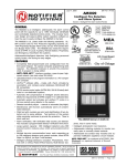
1
JWS-3 Installation and Operation Manual Document 53550 1/12/10 Rev: P/N: 53550:A1 A1 ECN: 10-018 Fire Alarm System Limitations While a fire alarm system may lower insurance rates, it is not a substitute for fire insurance! An automatic fire alarm system—typically made up of smoke detec- tors, heat detectors, manual pull stations, audible warning devices, and a fire alarm control panel with remote notification capability—can provide early warning of a developing fire. Such a system, however, does not assure protection against property damage or loss of life resulting from a fire. The Manufacturer recommends that smoke and/or heat detectors be located throughout a protected premise following the recommendations of the current edition of the National Fire Protection Association Standard 72 (NFPA 72), manufacturer's recommendations, State and local codes, and the recommendations contained in the Guide for Proper Use of System Smoke Detectors, which is made available at no charge to all installing dealers. These documents can be found at http://www.systemsensor.com/html/applicat.html. A study by the Federal Emergency Management Agency (an agency of the United States government) indicated that smoke detectors may not go off in as many as 35% of all fires. While fire alarm systems are designed to provide early warning against fire, they do not guarantee warning or protection against fire. A fire alarm system may not provide timely or adequate warning, or simply may not function, for a variety of reasons: bedrooms), smoking in bed, and violent explosions (caused by escaping gas, improper storage of flammable materials, etc.). Heat detectors do not sense particles of combustion and alarm only when heat on their sensors increases at a predetermined rate or reaches a predetermined level. Rate-of-rise heat detectors may be subject to reduced sensitivity over time. For this reason, the rate-ofrise feature of each detector should be tested at least once per year by a qualified fire protection specialist. Heat detectors are designed to protect property, not life. IMPORTANT! Smoke detectors must be installed in the same room as the control panel and in rooms used by the system for the connection of alarm transmission wiring, communications, signaling, and/or power. If detectors are not so located, a developing fire may damage the alarm system, crippling its ability to report a fire. Audible warning devices such as bells may not alert people if these devices are located on the other side of closed or partly open doors or are located on another floor of a building. Any warning device may fail to alert people with a disability or those who have recently consumed drugs, alcohol or medication. Please note that: • Strobes can, under certain circumstances, cause seizures in people with conditions such as epilepsy. • Studies have shown that certain people, even when they hear a fire alarm signal, do not respond or comprehend the meaning of the signal. It is the property owner's responsibility to conduct fire drills and other training exercise to make people aware of fire alarm signals and instruct them on the proper reaction to alarm signals. Particles of combustion or “smoke” from a developing fire may not reach the sensing chambers of smoke detectors because: • In rare instances, the sounding of a warning device can cause temporary or permanent hearing loss. • Barriers such as closed or partially closed doors, walls, or chimneys may inhibit particle or smoke flow. A fire alarm system will not operate without any electrical power. If • Smoke particles may become “cold,” stratify, and not reach the ceiling or upper walls where detectors are located. • Smoke particles may be blown away from detectors by air outlets. • Smoke particles may be drawn into air returns before reaching the detector. Smoke detectors may not sense fire where smoke cannot reach the detectors such as in chimneys, in or behind walls, on roofs, or on the other side of closed doors. Smoke detectors also may not sense a fire on another level or floor of a building. A second-floor detector, for example, may not sense a first-floor or basement fire. AC power fails, the system will operate from standby batteries only for a specified time and only if the batteries have been properly maintained and replaced regularly. Equipment used in the system may not be technically compatible with the control panel. It is essential to use only equipment listed for service with your control panel. The amount of “smoke” present may be insufficient to alarm smoke detectors. Smoke detectors are designed to alarm at various levels of smoke density. If such density levels are not created by a developing fire at the location of detectors, the detectors will not go into alarm. Telephone lines needed to transmit alarm signals from a premise to a Smoke detectors, even when working properly, have sensing limitations. Detectors that have photo-electronic sensing chambers tend to detect smoldering fires better than flaming fires, which have little visible smoke. Detectors that have ionizing-type sensing chambers tend to detect fast-flaming fires better than smoldering fires. Because fires develop in different ways and are often unpredictable in their growth, neither type of detector is necessarily best and a given type of detector may not provide adequate warning of a fire. The most common cause of fire alarm malfunction is inadequate Smoke detectors cannot be expected to provide adequate warning of fires caused by arson, children playing with matches (especially in 2 central monitoring station may be out of service or temporarily disabled. For added protection against telephone line failure, backup radio transmission systems are recommended. maintenance. To keep the entire fire alarm system in excellent working order, ongoing maintenance is required per the manufacturer's recommendations, and UL and NFPA standards. At a minimum, the requirements of NFPA 72 shall be followed. Environments with large amounts of dust, dirt or high air velocity require more frequent maintenance. A maintenance agreement should be arranged through the local manufacturer's representative. Maintenance should be scheduled monthly or as required by National and/or local fire codes and should be performed by authorized professional fire alarm installers Johnson Controls Web Server-3 Installation and Operation Manual - P/N: 53550:Rev: A1 1/12/10 Installation Precautions Adherence to the following will aid in problem-free installation with long-term reliability: WARNING - Several different sources of power can be connected to the fire alarm control panel. Disconnect all sources of power before servicing. The control unit and associated equipment may be damaged by removing and/or inserting cards, modules, or interconnecting cables while the unit is energized. Do not attempt to install, service, or operate this unit until this manual is read and understood. CAUTION - System Reacceptance Test after Software Changes. To ensure proper system operation, this product must be tested in accordance with NFPA 72 after any programming operation or change in site-specific software. Reacceptance testing is required after any change, addition or deletion of system components, or after any modification, repair or adjustment to system hardware or wiring. All components, circuits, system operations, or software functions known to be affected by a change must be 100% tested. In addition, to ensure that other operations are not inadvertently affected, at least 10% of initiating devices that are not directly affected by the change, up to a maximum of 50 devices, must also be tested and proper system operation verified. This system meets NFPA requirements for operation at 0°C to 49°C (32°F to 120°F) and at a relative humidity 93% ± 2% RH (non-condensing) at 32°C ± 2°C (90°F ± 3°F). However, the useful life of the system's standby batteries and the electronic components may be adversely affected by extreme temperature ranges and humidity. Therefore, it is recommended that this system and all peripherals be installed in an environment with a nominal room temperature of 1527° C/60-80° F. Verify that wire sizes are adequate for all initiating and indicating device loops. Most devices cannot tolerate more than a 10% I.R. drop from the specified device voltage. Like all solid state electronic devices this system may operate erratically or can be damaged when subjected to lightning-induced transients. Although no system is completely immune from lightning transients and interferences, proper grounding will reduce susceptibility. Overhead or outside aerial wiring is not recommended, due to an increased susceptibility to nearby lightning strikes. Consult with the Technical Services if any problems are anticipated or encountered. Disconnect AC power and batteries prior to removing or inserting circuit boards. Failure to do so can damage circuits. Remove all electronic assemblies prior to any drilling, filing, reaming, or punching of the enclosure. When possible, make all cable entries from the sides or rear. Before making modifications, verify that they will not interfere with battery, transformer, and printed circuit board location. Do not tighten screw terminals more than 9 in-lbs. Over-tightening may damage threads, resulting in reduced terminal contact pressure and difficulty with screw terminal removal. Though designed to last many years, system components can fail at any time. This system contains static-sensitive components. Always ground yourself with a proper wrist strap before handling any circuits so that static charges are removed from the body. Use static-suppressive packaging to protect electronic assemblies removed from the unit. Follow the instructions in the installation, operating, and program- ming manuals. These instructions must be followed to avoid damage to the control panel and associated equipment. FACP operation and reliability depend upon proper installation by authorized personnel. FCC Warning WARNING: This equipment generates, uses, and can radi- ate radio frequency energy and if not installed and used in accordance with the instruction manual, may cause interference to radio communications. It has been tested and found to comply with the limits for class A computing device pursuant to Subpart B of Part 15 of FCC Rules, which is designed to provide reasonable protection against such interference when operated in a commercial environment. Operation of this equipment in a residential area is likely to cause interference, in which case the user will be required to correct the interference at his own expense. Canadian Requirements: This digital apparatus does not exceed the Class A limits for radiation noise emissions from digital apparatus set out in the Radio Interference Regulations of the Canadian Department of Communications. This Class A digital apparatus complies with Canadian ICES-003 Le present appareil numerique n'emet pas de bruits radioelectriques depassant les limites applicables aux appareils numeriques de la classe A prescrites dans le Reglement sur le brouillage radioelectrique edicte par le ministere des Communications du Canada. Cet appareil numerique de la classe A est conforme a la norme NMB-003 du Canada. Intelligent Fire Integrator™ is a trademark of Johnson Controls Inc. NION® and VeriFire® are registered trademarks of Honeywell International Inc. Echelon® is a registered trademark and LonWorks™ is a trademark of Echelon Corporation. ARCNET® is a registered trademark of Datapoint Corporation. Microsoft® and Windows® are registered trademarks of the Microsoft Corporation. LEXAN® is a registered trademark of GE Plastics, a subsidiary of General Electric Company. ©2009 by Honeywell International Inc. All rights reserved. Unauthorized use of this document is strictly prohibited. Johnson Controls Web Server-3 Installation and Operation Manual - P/N: 53550:Rev: A1 1/12/10 3 Documentation Feedback Your feedback helps us keep our documentation up-to-date and accurate. If you have any comments, you can email us. Please include the following information: • Product name and version number (if applicable) • Manual page number • Your comment Send email messages to: [email protected] Please note this email address is for documentation feedback only. If you have any technical issues, please contact Technical Services. 4 Johnson Controls Web Server-3 Installation and Operation Manual - P/N: 53550:Rev: A1 1/12/10 Table of Contents Section 1 JWS-3 Features ........................................................................................................ 7 1.1: Product Description .......................................................................................................................................7 1.1.1: JWS-3 Features....................................................................................................................................7 1.2: Related Documentation .................................................................................................................................8 Table 1.1 Related Documentation ..........................................................................................................8 1.3: Agency Listings .............................................................................................................................................8 1.3.1: Compliance..........................................................................................................................................8 1.3.2: Installation ...........................................................................................................................................9 1.4: Environmental Requirements ........................................................................................................................9 1.5: Compatibility ..............................................................................................................................................10 1.6: Upgrade Information ...................................................................................................................................10 1.7: System Requirements ..................................................................................................................................10 1.8: System Architecture.....................................................................................................................................11 1.8.1: NFN Network Architecture ...............................................................................................................11 Figure 1.1 JWS-3 HS-NCM or NCM Architecture..............................................................................11 1.8.2: Standalone Panel Architecture...........................................................................................................11 Figure 1.2 JWS-3 Direct Panel Architecture........................................................................................11 Section 2 JWS-3 Embedded Installation............................................................................... 13 2.1: Required Equipment ....................................................................................................................................13 2.2: JWS-3 Installation Overview.......................................................................................................................13 2.2.1: JWS-3 PC Board Layout ...................................................................................................................14 Figure 2.1 JWS-3 Printed Circuit Board ..............................................................................................14 2.3: Installing a CAB3/CAB4 Cabinet ...............................................................................................................15 Figure 2.2 CAB-3/CAB-4 Series Installation Document, 15330 .........................................................15 2.4: Installing a CHS-4L Chassis........................................................................................................................16 Figure 2.3 Installing a CHS-4LChassis ................................................................................................16 2.5: Installing the JWS-3 Printed Circuit Board .................................................................................................17 Figure 2.4 Install JWS-3 Printed Circuit Board onto Chassis ..............................................................17 2.5.1: JWS-3 Power Supply Connection ....................................................................................................17 Table 2.1 Power Supply Specifications................................................................................................17 Figure 2.5 JWS-3 Power Connection ...................................................................................................18 2.5.2: Wiring Restrictions............................................................................................................................18 2.5.3: Installing the Network Communication Module ...............................................................................19 Table 2.2 Network Communication Module Details ...........................................................................19 Figure 2.6 HS-NCM Installation Document PN 54014 .......................................................................19 Figure 2.7 NCM Installation Document PN 51533 ..............................................................................................................................................19 2.6: Connecting an JWS-3 to an IP Network......................................................................................................20 Figure 2.8 IP Cable Connection ..........................................................................................................20 Table 2.3 JWS-3 to Fire System Connection Options..........................................................................20 2.7: Connecting an JWS-3 to a High Speed Network Control Module ..............................................................21 Figure 2.9 USB Connection .................................................................................................................21 Figure 2.10 NUP to NUP Connection ..................................................................................................22 2.8: Connecting an JWS-3 to a Network Control Module..................................................................................22 Figure 2.11 NUP to NUP Connection ..................................................................................................22 2.9: Connecting an JWS-3 Directly to a Fire Alarm Control Panel ...................................................................23 Figure 2.12 NUP to NUP Connection ..................................................................................................23 Section 3 JWS-3 Configuration ............................................................................................. 25 3.1: Configuration PC Preparation......................................................................................................................25 3.1.1: Connect the Configuration PC to the JWS-3.....................................................................................25 3.2: IP Network Configuration ...........................................................................................................................25 Johnson Controls Web Server-3 Installation and Operation Manual - P/N: 53550:Rev: A1 1/12/10 5 Table of Contents Section 4 JWS-3 Operation.................................................................................................... 27 4.1: Browser Security Settings............................................................................................................................27 4.2: JWS-3 Security ............................................................................................................................................27 Figure 4.1 JWS-3 Login Dialog............................................................................................................28 4.3: The JWS-3 Interface ....................................................................................................................................29 4.4: Events Tab....................................................................................................................................................29 Figure 4.2 JWS-3 Events Tab...............................................................................................................29 Figure 4.3 Events Summary .................................................................................................................30 4.5: Properties Tab ..............................................................................................................................................31 Figure 4.4 NUP Port Statistics..............................................................................................................32 Figure 4.5 Network Statistics ...............................................................................................................32 Figure 4.6 Version Information ............................................................................................................32 4.6: History Tab...................................................................................................................................................33 Figure 4.7 History Events Available ....................................................................................................33 Figure 4.8 Alarm History......................................................................................................................33 Figure 4.9 All History...........................................................................................................................33 4.7: Administration Tab ......................................................................................................................................34 4.7.1: E-mail Notification ...........................................................................................................................34 Figure 4.10 E-mail Configuration.........................................................................................................35 Figure 4.11 E-mail Profile Configuration.............................................................................................36 Figure 4.12 Sample E-mail Message ....................................................................................................37 Figure 4.13 Send Message....................................................................................................................37 4.7.2: System Settings..................................................................................................................................38 Figure 4.14 System Settings .................................................................................................................38 4.7.3: Time Zone Settings............................................................................................................................39 Figure 4.15 Time Zone Settings ...........................................................................................................39 4.7.4: Event Filter Settings ..........................................................................................................................40 Figure 4.16 Event Filter Settings ..........................................................................................................40 4.7.5: Node Mapping ...................................................................................................................................40 Figure 4.17 Node Mapping...................................................................................................................40 4.7.6: Automatic Point Detection ................................................................................................................41 Figure 4.18 Auto Detect Points ............................................................................................................42 Figure 4.19 Auto Point Detect Screen ..................................................................................................43 4.7.7: User Configuration ............................................................................................................................43 Figure 4.20 User Configuration............................................................................................................44 4.7.8: Active Users.......................................................................................................................................45 Figure 4.21 Active Users ......................................................................................................................45 A.1: Direct Connect Node Type Compatibility...................................................................................................47 Table A.1 Panel Communication Connection Table ............................................................................47 B.1: Direct Connection to the Gateway PC Board..............................................................................................49 Figure B.1 Configuration PC Direct Connection .................................................................................49 Table B.1 Cross Over Cable (568B).....................................................................................................50 Index ........................................................................................................................................ 51 6 Johnson Controls Web Server-3 Installation and Operation Manual - P/N: 53550:Rev: A1 1/12/10 Section 1 JWS-3 Features 1.1 Product Description The JWS-3 is a web-based device that acts as an HTML server that allows remote viewing of the NFN network (this includes high speed NFN networks) via the Internet or an Intranet. With the JWS-3 interface, the user can view the history of a fire alarm control panel (FACP), event status, device properties, and other information based on access permissions defined by the system administrator. All data available on the JWS-3 is a “snapshot” of the data on the NFN network at the time the browser requested the information. The JWS-3 communicates to NFN network version 5.0 and later. The JWS-3 interfaces to the Internet/Intranet using an IP-based wire Ethernet connection. The JWS-3 can also be used as web-based communication between the NFN network and VeriFire Tools. Refer to Appendix A, “JWS-3 Compatible Node Types”, on page 47 for supported panels and annunciators. 1.1.1 JWS-3 Features These are some of the features of the JWS-3. • Ability to view NFN network nodes, system statuses, and properties remotely using the Internet or Intranet. • Compatible with NFN network version 5.0 and above. • One JWS-3 supports multiple users. • Standard IP over Ethernet connection. • Up to 128 user accounts are supported. • Built-in password security and user access record • Supports Microsoft Internet Explorer 6.0 and above. • Intuitive web browser user interface. • Sends up to 50 E-mails in response to any system event. JWS-3 Installation and Operation Manual - P/N: 53550:Rev: A1 1/12/10 7 JWS-3 Features Related Documentation 1.2 Related Documentation Below is a list of documentation that relates to the use of the JWS-3. Table 1.1 Related Documentation For information on Refer to Part No. Compatible Devices Device Compatibility Document 15378 Cabinets & Chassis CAB-3/CAB-4 Series Installation Document 15330 Offline Programming Utility Veri•Fire™ Tools on-line help file Veri•Fire™ Medium Systems on-line help file JVeriFire-TCD LVeriFire-CD VeriFire-TCDNetworking NFN Manual NCM-W/F Installation Document HS-NCM-W/SF/MF MIB Media Interface Board Manual 51584 51533 54014 50255 Panels and Annunciators IFC-320 Installation/Operation/Programming Manual IFC-640 Installation/Operation/Programming Manual IFC2-640 Installation/Operation/Programming Manual IFC-3030 Installation/Operation/Programming Manual IFC2-3030 Installation/Operation/Programming Manual Network Control Annunciator (JNCA) Manual Network Control Annunciator-2 (JNCA-2) Manual Network Control Station (JNCS) Manual IFC-200 Instruction Manual IFC-300/400 Installation, Operation, and Programming Manual JDVC Series Digital Voice Command Manual 52858/52859/52860 51864/ 51865/51866 52835/52836/52637 52024/52026/52025 52563/52564/52565 51868 52570 52095 15511 15088 52567 1.3 Agency Listings NOTE: UL 864, 9th Edition—Intelligent Fire IntegratorTM systems work with products that have been UL 864, 9th Edition listed as well as products that have not received UL 864, 9th Edition certification. Operation of systems that are comprised of equipment that is UL 864, 9th Edition listed together with products that are not UL 864, 9th Edition listed requires the approval of the local Authority Having Jurisdiction (AHJ). CAN/ULC-S559-04, 1st Edition—Intelligent Fire IntegratorTM systems work with products that have been CAN/ULC-S559-04, 1st Edition listed as well as products that have not received CAN/ ULC-S559-04, 1st Edition certification. Operation of systems that are comprised of equipment that is CAN/ULC-S559-04, 1st Edition listed together with products that are not CAN/ULC-S55904, 1st Edition listed requires the approval of the local Authority Having Jurisdiction (AHJ). 1.3.1 Compliance This product has been investigated to, and found to be in compliance with the following standards. National Fire Protection Association • NFPA 72—National Fire Alarm Code Underwriters Laboratories • 8 UL-864—Control Units for Fire Alarm Systems, Ninth Edition • UL-1076—Proprietary Burglar Alarm Units and Systems, Fifth Edition • UL-2017—General-Purpose Signaling Devices and Systems, First Edition JWS-3 Installation and Operation Manual - P/N: 53550:Rev: A1 1/12/10 Environmental Requirements JWS-3 Features Underwriters Laboratories Canada • CAN/ULC-S527-99—Standard for Control Units for Fire Alarm Systems, Second Edition • CAN/ULC-S559-04—Equipment for Fire Signal Receiving Centres and Systems, First Edition 1.3.2 Installation This product is intended to be installed in accordance with the following regulatory agencies. Local • AHJ—Authority Having Jurisdiction National Fire Protection Association • NFPA 70—National Electrical Code • NFPA 72—National Fire Alarm Code • NFPA 101—Life Safety Code Underwriters Laboratories • UL-1076—In certified applications, the unit shall be installed in accordance with Proprietary Burglar Alarm Units and Systems, Fifth Edition Underwriters Laboratories Canada ! • C22.1–98—Canadian Electrical Code, Part I (Twentieth Edition), Safety Standard for Electrical Installation • CAN/ULC-S524-06—Standard for the installation of Fire Alarm Systems, Fifth Edition • CAN/ULC-S561-03—Installation and Services for Fire Signal Receiving Centres and Systems, First Edition WARNING: Installation Improper installation, maintenance, and lack of routine testing could result in system malfunction. 1.4 Environmental Requirements This product must be installed in the following environmental conditions: • Temperature range of 0°C to 49°C (32°F - 120°F). • 93% humidity non-condensing at 30°C (86°F). JWS-3 Installation and Operation Manual - P/N: 53550:Rev: A1 1/12/10 9 JWS-3 Features Compatibility 1.5 Compatibility NOTE: The JWS-3 requires that at least one node on the NFN network be an IFC-320/640/2640/3030/2-3030 series panel. JWS-3 does not run on an NFN network with no IFC-320/640/2640/3030/2-3030 series panels. The JWS-3 acts like any other node on an NFN network (this includes high speed NFN networks). For information about direct panel connections supported, refer to Appendix A.1, “Direct Connect Node Type Compatibility”, on page 47 NOTE: The JWS-3 is not intended as a primary annunciator and is ancillary in nature. No NCM W/F PC board is required when the JWS-3 connects directly to a supported Johnson Controls panel when it is a standalone panel. 1.6 Upgrade Information Firmware for systems running JWS-3 versions prior to 4.0 should not be upgraded unless there is an IFC-320/640/2-640/3030/2-3030 series panel on the system. JWS-3 does not operate on an NFN network with no IFC-320/640/2-640/3030/2-3030 series panels. 1.7 System Requirements • Java™ version 6 or later • Microsoft® Internet Explorer version 6.0 or later NOTE: The JWS-3 application supports only Microsoft Internet Explorer®. 10 JWS-3 Installation and Operation Manual - P/N: 53550:Rev: A1 1/12/10 System Architecture JWS-3 Features 1.8 System Architecture These are the connections options for the JWS-3 architecture: • NFN network connection—A connection is made to an HS-NCM that is on the same high speed NFN network as the JWS-3, or to an NCM that is on the same NFN network as the JWS3 (Figure 1.1). • Direct panel connection—A connection is made directly to a supported Johnson Controls panel (Figure 1.2). Refer to Appendix A, “JWS-3 Compatible Node Types”, on page 47 for supported panels. An Internet or Intranet IP network connection is used with both architectures. 1.8.1 NFN Network Architecture CAB 3/4 Cabinet with JWS-3 Assembly and HSNCM W/SF/MF or NCM W/F Board Internet/Intranet PC Browser Interface HS-NCM W/SF/MF or NCM W/F HS-NCM W/SF/MF or NCM W/F NFN Network Supported FACP Supported FACP Figure 1.1 JWS-3 HS-NCM or NCM Architecture 1.8.2 Standalone Panel Architecture Internet/Intranet PC Browser Interface Supported Notifier FACP with Web Server Assembly Figure 1.2 JWS-3 Direct Panel Architecture JWS-3 Installation and Operation Manual - P/N: 53550:Rev: A1 1/12/10 11 JWS-3 Features 12 System Architecture JWS-3 Installation and Operation Manual - P/N: 53550:Rev: A1 1/12/10 Section 2 JWS-3 Embedded Installation 2.1 Required Equipment The JWS-3 requires the following: JWS-3 Assembly The following are shipped with the JWS-3: • JWS-3 printed circuit board • PNET-1 surge suppressor (P/N PNET-1) • RJ45 to RJ45 standard Ethernet network cable (P/N 75585—used to connect the JWS-3 board to PNET-1 surge suppressor • NUP to NUP Cable—(P/N 75556) used to connect the JWS-3 board to an HS-NCM-W/SF/ MF, an NCM-W/F, or an FACP • Wire Leads to NUP Network Communications Module power cable (P/N 75583) Network Components • RJ45 to RJ45 standard Ethernet network cable—customer’s internet or intranet connection to the JWS-3 board • NFN network—version 5.0 or above (sold separately) • High-Speed Network Communication Module: HS-NCM-W/SF/MF or Network Communication Module: NCM-W/F—used to facilitate network communication between the JWS-3 and NFN network (sold separately) NOTE: No HS-NCM-W/SF/MF or NCM-W/F is required when the JWS-3 connects directly to a supported Johnson Controls panel when it is a standalone panel. Refer to Section A.1, “Direct Connect Node Type Compatibility” on page 47 for a list of supported panels. Cabinet and Hardware (sold separately) • CAB-3/CAB-4 series cabinet • CHS-4L chassis Customer Supplied Equipment • A computer to monitor and configure the JWS-3 2.2 JWS-3 Installation Overview This is the recommend installation order: • “Installing a CAB3/CAB4 Cabinet” on page 15 • “Installing the JWS-3 Printed Circuit Board” on page 17. • “Installing the Network Communication Module” on page 19 (if applicable). JWS-3 Installation and Operation Manual - P/N: 53550:Rev: A1 1/12/10 13 JWS-3 Embedded Installation JWS-3 Installation Overview 2.2.1 JWS-3 PC Board Layout USB “A” Host (J13) USB “B” Device (J14) Ethernet Connector (J8) Mounting Hole with Surrounding Grounding Area (5 locations) NUP A Serial Data Connector (J6) not used (J7) TB6: NO Com Not Used NC TB1: -24 V Out +24 V Out -24 V In +24 V In Figure 2.1 JWS-3 Printed Circuit Board 14 JWS-3 Installation and Operation Manual - P/N: 53550:Rev: A1 1/12/10 Installing a CAB3/CAB4 Cabinet JWS-3 Embedded Installation 2.3 Installing a CAB3/CAB4 Cabinet Install a new CAB-3/CAB-4 series cabinet according to the requirements of the local authority having jurisdiction or prepare an existing CAB-3/CAB-4 series cabinet that houses a supported Johnson Controls panel or annunciator. Refer to Appendix A, “JWS-3 Compatible Node Types”, on page 47for list of supported panels and annunciators. NOTE: The CAB3/CAB4 cabinet is ordered separately. For installation details, refer to the CAB-3/ CAB-4 Series Installation Document, 15330 and or the panel’s or annunciator’s documentation. NOTE: Knockouts are provided on the unit so that the field wiring may be run in conduit if required by the local authority having jurisdiction. All field wiring connections are intended to be made at the installation wiring terminals provided as part of the unit. CAB-3/CAB-4 Series Cabinets Product Installation Document PN 15330:I 10/23/07 07-695 1 General All cabinets are fabricated from 16 gauge steel. The cabinet consists of two basic components: a backbox and a locking door. The key-locked door is provided with a pin-type hinge, two keys, and the necessary hardware to mount the door to the backbox. The backbox has been engineered to provide ease-of-entry for the installer. Knockouts are positioned at numerous points to let the installer bring conduit into the enclosure easily. Doors can be mounted on the left or right-hand side. The same hinge works in both configurations, so that this choice can be made in the field. The door opens 180°. Cabinets are available in five sizes: A through D, and AA. The outside dimensions are noted on each enclosure diagram. “A” size accommodates one chassis, a power supply, and two 26 AH batteries; “D” size accommodates four chassis, a power supply, and two 26 AH batteries; “AA” size holds one chassis with no compartment for batteries. A trim ring option is available for semi-flush mounting. The CAB-3/CAB-4 Series is compatible with multiple chassis including the CHS-M2, CHS2-M2, CHS-M3, CHS-4, CHS-4L, CHS-4N, CHS-BH, CHS-PS, CA-1, and CA-2. Note: CAB-4 series backboxes and doors are sold separately. CAB door RH.wmf CAB door LH.wmf 2 Before You Begin The option of mounting doors in either a left/right hand configuration will aid in installation and service when two control panels are mounted in a confined area or side by side (as shown). In this manner the doors can be opened “barn door” style, permitting an open work space. Note that in this type of installation it is necessary to leave enough space between cabinets to insert a key into the locks on the door frames. IMPORTANT: Attach the two hinges and two alignment tabs to the backbox before any equipment is installed. With chassis installed, space is very limited. Display Interface Assembly Note: When the door is left-hand mounted, the Display Interface Assembly (DIA) dress panel cannot be opened when the door is at less than a 120° angle to the cabinet. If you are using the left-hand mounting option, be sure that the door can open at least 120°. This is especially important if the cabinet is to be mounted in a closed area, such as a closet or utility room. 3 Door Assembly Instructions Hinges can be either left or right hand mounted. The illustrations and text depict a left hand mounted example. For a right hand mounting, simply substitute right for left in the instructions. 1. Insert door hinges (A) into the top and bottom slots of the side to be hinged (in this case the LEFT side). Secure the hinges to the studs in the backbox with the #8 hex nuts provided. Note that the small hole on the outer tab faces outward. 2. Thread stud (B) into the BOTTOM hinge first. Thread from the bottom up. Place the grounding “star” washer on the stud. Place the door's lower corner onto this stud. Placing the door on the lower stud first provides a place for the door to rest while you complete the assembly. 3. Align the door on the backbox, so that the door sits directly under the top hinge. Thread remaining stud (B) into the TOP hinge and through the hole in the top of the door. Your door should now swing freely. Figure 2.2 CAB-3/CAB-4 Series Installation Document, 15330 JWS-3 Installation and Operation Manual - P/N: 53550:Rev: A1 1/12/10 15 JWS-3 Embedded Installation Installing a CHS-4L Chassis 2.4 Installing a CHS-4L Chassis A chassis holds the gateway within a CAB-3/CAB-4 series cabinet. A CHS-4L chassis fits into any CAB-3/CAB-4 series cabinet row except for the bottom row, which provides battery housing and does not have PEM studs for mounting. Follow these instructions to install a CHS-4L chassis in a CAB-3/CAB-4 series cabinet. Step 1. Position the chassis so the PEM cabinet studs are aligned with the chassis mounting holes, and mount the chassis onto the cabinet. Step 2. Secure the chassis to the PEM studs with the two hex nuts (PN 36047) provided with the chassis. PEM Studs Hex Nuts Figure 2.3 Installing a CHS-4LChassis 16 JWS-3 Installation and Operation Manual - P/N: 53550:Rev: A1 1/12/10 Installing the JWS-3 Printed Circuit Board JWS-3 Embedded Installation 2.5 Installing the JWS-3 Printed Circuit Board Install the JWS-3 printed circuit board onto the mounting studs on the CHS-4L chassis, making sure to use only the mounting holes bordered by grounding area. Grounding area Figure 2.4 Install JWS-3 Printed Circuit Board onto Chassis NOTE: There must be enough clearance on the right side of the printed circuit board to allow an Ethernet cable to be connected to the Ethernet port. 2.5.1 JWS-3 Power Supply Connection The JWS-3 requires +24VDC @450mA nominal and supervised battery backup in accordance with local code requirements. Outside Canada, the JWS-3 can be powered by any regulated, UL 1481 listed, power limited, battery backed, +24 VDC power supply. For Canadian installation, The JWS3 must be powered by a ULC listed Fire Alarm Control Unit or a ULC listed power supply for fire application. Conform to UL or ULC standards as applicable in your area. Table 2.1 Power Supply Specifications NOMINAL Input Voltage +24VDC Input Current @ +24VDC 450 mA without NCM or HS-NCM JWS-3 Installation and Operation Manual - P/N: 53550:Rev: A1 1/12/10 17 JWS-3 Embedded Installation Installing the JWS-3 Printed Circuit Board TB1 24 V IN Figure 2.5 JWS-3 Power Connection NOTE: All wiring from the power supply is power limited, and a separation of at least ¼” (6.35 mm) must be maintained between power limited and non-power limited wiring. ! CAUTION: Power Sources Different sources of power are used in conjunction with the JWS-3 product. Disconnect all sources of power before servicing. This device and associated equipment may be damaged by removing and/or inserting cards, modules or interconnecting cables while this unit is powered. This damage may adversely affect the operation of this unit, but its effect may not be readily apparent. For specific information about power configurations involving fire alarm control panels and network communications modules, refer to Embedded Gateway Power Connections, PN 53612. 2.5.2 Wiring Restrictions NOTE: All wiring connections are supervised and power limited. NOTE: USB and NUP wiring connections to the HS-NCM must be located within 20 feet and encased in conduit within the same room. NOTE: In Canada, if the gateway is installed in a separate cabinet, the cabinet must be connected to the Fire Alarm Control Panel (FACP) with a close nipple fitting. RS232 (NUP) • Line Impedance 5k ohm • Max Distance 50 feet Ethernet 18 • Line Impedance 100 ohm • Max Distance 100 meters JWS-3 Installation and Operation Manual - P/N: 53550:Rev: A1 1/12/10 Installing the JWS-3 Printed Circuit Board JWS-3 Embedded Installation USB • Line Impedance 90 ohm ±15% • Max Distance 40 meters 2.5.3 Installing the Network Communication Module Install the type of network communication module you will use (whether high speed or not, wire or fibre) onto the chassis in the new CAB3/CAB4 cabinet or an existing panel’s or annunciator’s cabinet. Table 2.2 Network Communication Module Details HIGH SPEED NFN NETWORKS—USE HS-NCM ONLY NFN NETWORKS—USE NCM ONLY Use the High SpeedNetwork Control Module configuration that fits your installation needs. • HS-NCM-W with twisted pair wire • HS-NCM-SF with single mode fiber-optic cable • HS-NCM-MF with multimode fiber-optic cable Use the Network Control Module configuration that fits your installation needs. • NCM-W with twisted pair wire • NCM-F with fiber-optic cable NOTIFIER is a Honeywell company. 12 Clintonville Road Northford, CT 06472-1610 USA 203-484-7161 • FAX 203-484-7118 www.notifier.com 12 Clintonville Road Northford, CT 06472-1653 USA 203-484-7161 • FAX 203-484-7118 www.notifier.com HS-NCM-W, HS-NCM-MF, HS-NCM-SF, HS-NCM-WMF, HS-NCM-WSF, HS-NCM-MFSF NCM Installation Document Network Communications Module NCM-W, NCM-F High Speed Network Communications Module Product Installation Document PN 54014:A 01/23/08 07-XXX PN 51533:B 11/29/2005 05-238 1 Product Overview 1 UL 864 Compliance The High-Speed Network Communications Module (HS-NCM) provides a means for connecting specific Notifier fire alarm control products to High-Speed NOTI•FIRE•NET™. There are six types of HS-NCMs available: HS-NCM-W for connecting nodes with twisted-pair wire; HS-NCM-MF and HS-NCM-SF are used for connecting nodes with fiber-optic cable; HS-NCM-WMF and HS-NCM-WSF are used for connecting nodes with fiber-optic cables to nodes with twistedpair wire; HS-NCM-MFSF for connecting nodes with multi-mode fiber cable to nodes with single-mode fiber cable. The following UL 9th Edition equipment may be used with the HS-NCM: 1.1 Products Subject to AHJ Approval This product has been certified to comply with the requirements in the Standard for Control Units and Accessories for Fire Alarm Systems, UL 864 9th Edition. The following products have not received UL 864 9th Edition certification and may only be used in retrofit applications. Operation of the NCM-W, NCM-F with products not tested for UL 864 9th Edition has not been evaluated and may not comply with NFPA 72 and/or the latest edition of UL 864. These applications will require the approval of the local Authority Having Jurisdiction (AHJ). • NFS2-3030 • NFS2-640 • NFS-320 • NCA-2 • • • • DVC One HS-NCM can provide network communication for up to two nodes (including fire alarm control panels and network annunciators). The HS-NCM can also be configured as a repeater. In this configuration, the HS-NCM can boost data signals between network nodes to extend communication distances or to pass data transmissions between two differently configured network segments when wire and fiber co-exist on a network. For limitations and network wiring information for the HSNCM in repeater mode, refer to the High-Speed Noti•Fire•Net Manual. When using the HS-NCM as a repeater, the node address for the HS-NCM must be set to zero (default). The node address can be changed through a fire alarm control panel’s network programming or through VeriFire Tools. Refer to the VeriFire™ Tools CD on-line help file. In most applications, one NCM is required per NOTI•FIRE•NET™ node (including fire alarm control panels and network annunciators) . Even though the NCM has two NUP ports, only one may be connected to a NOTI•FIRE•NET™. node. Except in some DVC applications, do not connect two NCMs via NUP ports (aka “NUP to NUP”). For instructions on the additional capabilities available with the DVC, refer to the DVC Manual. • Input power requirements: 24 VDC, 0.375 amps, regulated, power-limited compatible power supply UL/ULC listed for fire protective signalling use. • Communications circuit requirements: Refer to the High-Speed Noti•Fire•Net Manual for segment length limitations. For instructions on the additional capabilities available with the DVC, refer to the DVC Manual. • 2 The Network Communications Module for Wire (HS-NCM-W) Supports twisted-pair wire medium. NFPA Style 4 (Class B) operation or NFPA Style 7 (Class A) operation. • Transformer coupling provides electrical isolation between nodes. • Pluggable terminal wiring with strain relief. • Pluggable service connector (feeds signal directly through) in the event that power must be removed from a node (HS-NBB). • Data is regenerated at each node. • Two network ports to allow simultaneous connection to fire alarm control panel and to programming computer. • Enables software and database upload/download over High-Speed Noti•Fire•Net. • Channel B Connection Input power requirements: 24 VDC , 0.11 amps, regulated, power-limited compatible power supply UL/ULC listed for fire protective signalling use. Communications circuit requirements: Refer to the NOTI•FIRE•NET™ Manual (Network Version 4.0 and Higher) for wiring length and threshold information. USB Connections EtherNet Connection Ground Fault Detection Switches S1=CH. A S2=CH. B NUP Ports HS-NCMwire.wmf • • Channel A Connection AM2020/AFP1010 MIB NAM-232 2 Product Overview The Network Communications Module (NCM) provides a means for connecting specific Notifier fire alarm control products to NOTI•FIRE•NET™. There are two types of NCMs available: NCM-W for connecting nodes with twisted-pair wire, and NCM-F for connecting nodes with fiber-optic cable. Figure 1 HS-NCM-W Figure 2.6 HS-NCM Installation Document PN 54014 Figure 2.7 NCM Installation Document PN 51533 BE SURE TO INSTALL THE CORRECT SPEED NETWORK CONTROL MODULE, BASED ON WHETHER YOU HAVE A HIGH SPEED NFN NETWORK OR NOT. JWS-3 Installation and Operation Manual - P/N: 53550:Rev: A1 1/12/10 19 JWS-3 Embedded Installation Connecting an JWS-3 to an IP Network 2.6 Connecting an JWS-3 to an IP Network This allows the JWS-3 to communicate through your IP network (Internet or Intranet) Step 1. Plug the PNET-1 surge suppressor into the JWS-3 Ethernet connector. Step 2. Plug the RJ45 cable into the PNET-1. Step 3. Plug the RJ45 cable into your IP network. To Internet or Intranet PNET-1 Ethernet Connector (J8) Customer Supplied Cable Figure 2.8 IP Cable Connection NOTE: The Ethernet wire must be connected to through the PNET-1 surge suppressor. t NOTE: The Ethernet port is power limited. Find Your Fire System Connection Option Once the JWS-3 is connected to the IP network, connect it to either a fire alarm control panel or an appropriate network control module. Refer to Table 2.3, "JWS-3 to Fire System Connection Options" for details. NOTE: Make only one of these connections. Table 2.3 JWS-3 to Fire System Connection Options 20 When Connecting... Refer to ...to a high speed NFN network consisting exclusively of High Speed compatible panels Section 2.7, “Connecting an JWS-3 to a High Speed Network Control Module” on page 21 ...to an NFN network Section 2.8, “Connecting an JWS-3 to a Network Control Module” on page 22 directly to a fire alarm control panel to be accessed through the JWS-3 Section 2.9, “Connecting an JWS-3 Directly to a Fire Alarm Control Panel” on page 23 JWS-3 Installation and Operation Manual - P/N: 53550:Rev: A1 1/12/10 Connecting an JWS-3 to a High Speed Network Control Module JWS-3 Embedded Installation 2.7 Connecting an JWS-3 to a High Speed Network Control Module • • • Use an HS-NCM-W for a twisted pair wire connection. Use an HS-NCM-SF for a single mode fiber-optic cable connection. Use an HS-NCM-MF for a multimode fiber-optic cable connection. Connecting the JWS-3 to an HS-NCM-W/SF/MF allows the gateway to communicate with devices on a high speed NFN network. Connect an JWS-3 to a High Speed Network Control Module using either of these methods: USB to USB Cable Connection Connect USB A on the JWS-3 to USB B on the HS-NCM-W/SF/MF, or connect USB B on the JWS-3 to USB A on the HS-NCM-W/SF/MF. USB cable Connect to an HS-NCM-W/MF/SF NUP A (J6) Figure 2.9 USB Connection JWS-3 Installation and Operation Manual - P/N: 53550:Rev: A1 1/12/10 21 JWS-3 Embedded Installation Connecting an JWS-3 to a Network Control Module NUP to NUP Cable Connection Connect the cable between to the JWS-3 circuit board’s NUP connector and an HS-NCM-W/SF/ MF NUP connector. NUP to NUP cable PC Board NUP A (J6) USE NUP A ONLY Connect to an HS-NCM-W/SF/MF Figure 2.10 NUP to NUP Connection 2.8 Connecting an JWS-3 to a Network Control Module • • Use an NCM-W for a twisted pair wire connection. Use an NCM-F for a fiber-optic cable connection. NUP to NUP Cable Connection Connecting the JWS-3 to an NCM-W/F allows the gateway to communicate with devices on an NFN network. NUP to NUP cable USE NUP A ONLY Connect to an NCM-W/F NUP A (J6) Figure 2.11 NUP to NUP Connection 22 JWS-3 Installation and Operation Manual - P/N: 53550:Rev: A1 1/12/10 Connecting an JWS-3 Directly to a Fire Alarm Control Panel JWS-3 Embedded Installation 2.9 Connecting an JWS-3 Directly to a Fire Alarm Control Panel NUP to NUP Cable Connection Refer to Appendix A.1, “Direct Connect Node Type Compatibility”, on page 47 for a list of compatible panels. NUP to NUP cable USE NUP A ONLY Connect to a supported Fire Alarm Control Panel NUP A (J6) Figure 2.12 NUP to NUP Connection JWS-3 Installation and Operation Manual - P/N: 53550:Rev: A1 1/12/10 23 JWS-3 Embedded Installation 24 Connecting an JWS-3 Directly to a Fire Alarm Control Panel JWS-3 Installation and Operation Manual - P/N: 53550:Rev: A1 1/12/10 Section 3 JWS-3 Configuration 3.1 Configuration PC Preparation ! CAUTION: Multiple JWS-3 Installations JWS-3s should be installed and configured one at a time because all JWS-3 use the same default IP address and node number. NOTE: You must have completed the installation of the JWS-3 before you proceed with this preparation (refer to “JWS-3 Embedded Installation” on page 13). 3.1.1 Connect the Configuration PC to the JWS-3 If your Configuration PC is on the same IP network you connected the JWS-3 to in the step, “Connecting an JWS-3 to an IP Network” on page 20, then your Configuration PC is already connected to the JWS-3. Proceed to “IP Network Configuration” on page 25. Otherwise, refer to Appendix B.1, “Direct Connection to the Gateway PC Board”, on page 49. 3.2 IP Network Configuration Step 1. Once JWS-3 is powered and physically connected to the network, open a browser from a PC on the same network, and browse to the default address: 192.168.1.2 This launches the JWS-3 interface. Step 2. Log into JWS-3. Refer to “Browser Security Settings” on page 27 and “JWS-3 Security” on page 27. Step 3. From the JWS-3, click the Administration tab, and then choose System Settings from the list on the left. a. Type in the IP address into the “IP address” field. • • A JWS-3 user will type this IP address into their browser to connect to the JWS-3. If the JWS-3 is to be used on the internet, you may need to independently set up a router and/or fire-wall so the internet-based applications can locate and access the JWS-3. Contact your appropriate MIS personnel for details. b. Enter the Subnet Mask into the “Subnet Mask” field. • • This is the IP subnet mask the JWS-3 should use to determine whether a connection came from a local network or should be routed on to another network. All of the IP settings for the JWS-3 must be on the same subnet for communications to be established between the JWS-3 and a browser. c. Type in the values into the “IP address for routing back to Internet” field. • • This sets the IP of a router that the JWS-3 can use to locate the browser with which it is communicating. This sets a path for the JWS-3 to use to communicate back to the connecting browser. d. If applicable to your application, select an NCM Threshold and Network Styles. • • • The NCM threshold can be set to high or low. The network style can be set to style 4 or style 7. Refer to the NCM documentation for more details on these fields. Step 4. Refer to for information about configuring additional settings. JWS-3 Installation and Operation Manual - P/N: 53550:Rev: A1 1/12/10 25 JWS-3 Configuration IP Network Configuration Step 5. The configuration of JWS-3 is complete and it should be operational. Refer to “JWS-3 Operation” on page 27 for details. 26 JWS-3 Installation and Operation Manual - P/N: 53550:Rev: A1 1/12/10 Section 4 JWS-3 Operation 4.1 Browser Security Settings These Microsoft® Internet Explorer® settings for trusted sites MUST be made before you use the JWS-3. • Enter your Web Server’s IP address (if you did not change the initial IP address in , enter the default IP address: 192.168.1.2). • Un-check the “Require server verification (https:) for all sites in this zone” selection. NOTE: If you started the JWS-3 before making the Trusted Sites settings shown above, please shut down your browser and make the Internet Options settings from Control Panel. 4.2 JWS-3 Security There are factory set User Name and Password entries. The system administrator should modify these User Name and Password as soon as possible to provide the system with security. The password must be 8 characters. The default User Name and Password are: User Name Password admin 00000000 JWS-3 Installation and Operation Manual - P/N: 53550:Rev: A1 1/12/10 27 JWS-3 Operation JWS-3 Security When the JWS-3 is started, a log in must be performed. Functions assigned by the system administrator determine what access the user will have. Figure 4.1 JWS-3 Login Dialog NOTE: Passwords are case sensitive. 28 JWS-3 Installation and Operation Manual - P/N: 53550:Rev: A1 1/12/10 The JWS-3 Interface JWS-3 Operation 4.3 The JWS-3 Interface Browser The JWS-3 interface is an html page type format that displays information about all points present and active on a ONYXWorks™ network. The recommended internet browser is Microsoft Internet Explorer. For details on using Microsoft Internet Explorer, consult Microsoft’s documentation or help file. Output Buttons Many of the JWS-3 interface screens include output buttons to allow exporting or printing. The output buttons perform these functions: Export To Text—Opens a browser pop-up window which contains the information on the current JWS-3 screen in plain text format. Export To HTML—Opens a browser pop-up window which contains the information on the current JWS-3 screen in HTML format. Print—Opens the Print dialogue from the browser File menu. This lets you print the information on the current JWS-3 screen to a configured printer. Tabs Four tabs in the upper left area of the interface provide access to the JWS-3’s different features. The following pages describe the features available under each tab. 4.4 Events Tab When JWS-3 first launches, the events tab is shown. The events tab shows two sets of events: • New Events • Acknowledged Events. The JWS-3 Events tab navigates to the initial screen (shown in this example). Figure 4.2 JWS-3 Events Tab Event Information The Events Tab can display nine pieces of information about each new or acknowledged event: JWS-3 Installation and Operation Manual - P/N: 53550:Rev: A1 1/12/10 29 JWS-3 Operation Events Tab • Actual Time • Node • Point • Status • Trouble Status • Device Type • Description • Zone • Zone Label Show/Hide Columns Right-clicking the heading of any column of information brings up options that let you customize the view. Resize And Reposition Columns Click and drag a column, and then drop it in a new location to reposition it. Move the pointer over the border between two columns until a resize tool appears ( ). Then, click the column border, drag it to make the column wider or narrower, and release it. You can show, hide, resize and reposition columns to more easily view the data you need most. Events Summary At the bottom of the Events Tab, JWS-3 displays a summary of all events received: Figure 4.3 Events Summary 30 JWS-3 Installation and Operation Manual - P/N: 53550:Rev: A1 1/12/10 Properties Tab JWS-3 Operation 4.5 Properties Tab Panel And Device Properties In the Properties Tab, panels and devices on the network are represented by hyperlinks on the left side of the properties display area. These screens are for viewing panel/network device status and property settings. Click an object in the left panel to display values of its key properties in the right panel. In addition to fire alarm control panels, the Web Browser also allows you to view network devices such as network devices such as the Intelligent Fire Workstation (IFW), Network Control Annunciator (JNCA) and the JNFN Gateway. Click a device listed in the object panel to display details about that device in the property/value panel. NOTE: Reference the pertinent control panel user manual for property details. Click the browser Refresh button to view device properties updated in real time. JWS-3 Installation and Operation Manual - P/N: 53550:Rev: A1 1/12/10 31 JWS-3 Operation Properties Tab Diagnostic Information Diagnostic information can also be viewed from the properties tab. Expand the Diagnostics folder to access this information. Statistics are available for NUP ports and for the network at large. Figure 4.4 NUP Port Statistics Figure 4.5 Network Statistics NOTE: Only IFC/IFC2-3030, IFC/IFC2-640, IFC-320, JNCA, JNCA-2 will have Network Statistics information displayed. Information is also available about the version levels of panels and their components. Figure 4.6 Version Information 32 JWS-3 Installation and Operation Manual - P/N: 53550:Rev: A1 1/12/10 History Tab JWS-3 Operation 4.6 History Tab Panel History The History Tab shows a history of the panels on the fire alarm network. For each panel, up to 1000 of the most recent items are available. Clicking the History folder under a panel name on the left side of the display shows how many general history and alarm events are available for that panel. Figure 4.7 History Events Available Figure 4.8 Alarm History Figure 4.9 All History JWS-3 Installation and Operation Manual - P/N: 53550:Rev: A1 1/12/10 33 JWS-3 Operation Administration Tab Diagnostic Information Diagnostic information can also be displayed from the history tab. Under the diagnostic folder, click the appropriate heading to display the following information: • Authorization Log—a record of each time a user logged on or off the JWS-3, or attempted to • E-mail Log—a record of E-mail notification messages sent by the JWS-3. Refer to • General Log—a general record of information processed by the JWS-3 including internal operations • HTTP Log—a record of hypertext traffic the JWS-3 has handled Up to 1000 of the most recent items of each type are shown. 4.7 Administration Tab The Administration tab selections configure various JWS-3 settings. Administrators can decide whether to allow all users, or only administrative users, to change settings. 4.7.1 E-mail Notification NOTE: JWS-3 does not support e-mail servers that require e-mail authentication. Make sure your e-mail server is not set to require e-mail authentication. Summary The e-mail notification feature enables the administrator to configure the JWS-3 to automatically send event information via e-mail to a select group of users. E-mail recipients receive events according to the profiles they have been assigned. The JWS-3 can support a maximum of ten profiles, and an e-mail recipient can be assigned to all ten profiles. Each of the ten profiles support a maximum of five e-mail addresses.E-mail notification also provides the capability to send e-mail directly from the JWS-3 in real time. E-Mail Notification Features The following lists some of the benefits that the e-mail notification feature provides: • Ten Profiles • Send up to 50 e-mails in response to any system event. • Quickly Enable and Disable e-mail feature. • Create your own custom messages that will be included with the e-mailed system event. • Easily send e-mail “live” to any configured e-mail recipient. E-Mail Configuration You will need the following information from your Internet Service Provider (ISP) or Local Area Network (LAN) administrator. The JWS-3 does not provide authentication information. Outgoing Mail IP Address (SMTP) This is the mail server’s IP address. The JWS-3 does not support DNS; therefore, you will need the address in dotted decimal form (XXX.XXX.XXX.XXX). From Address (optional) Enter an e-mail address if you want responses to be sent to if you set up an E-Mail Profile and select Send Test Message. Also this is entry may not be an optional for cell phone service provider systems that support e-mail. 34 JWS-3 Installation and Operation Manual - P/N: 53550:Rev: A1 1/12/10 Administration Tab JWS-3 Operation Mail User This is an SMTP server setting. Leave this field blank unless your network administrator indicates otherwise. Figure 4.10 E-mail Configuration E-mail Profiles Profiles define the e-mail addresses of the recipients assigned that profile, along with the nodes and event types that will initiate an e-mail message. Profiles filter e-mail notification by event type. The six event types are Fire Alarm, Pre-Alarm, Security, Supervisory, Trouble, and Other. To Setup E-mail Profiles 1. Click the Administration tab. 2. Click the E-Mail Notification folder. 3. Click the E-mail Profiles subfolder to expand the selection to display the ten profiles. 4. Click the profile to define. 5. Enter the e-mail addresses to be included in the profile for notification. 6. Choose the node (panel type) to be included for e-mail notification. 7. Choose the event types to be included for e-mail notification. Note that these are set on a pernode basis. 8. Design custom messages. 9. After making all settings for the profile, click Save to save the e-mail profile. 10. To verify your e-mail profile setup; click Test to send the following message to recipients for this profile. NOTE: This is an automatically generated test message; its content cannot be edited. The Fire Alarm Web Server at site "NFN Web Server" generated this message in response to an operator test of e-mail profile #1. Your e-mail address has been listed in the web server to be notified in the case of an event of the type listed above. Please contact your system administrator if you have been inadvertently notified. JWS-3 Installation and Operation Manual - P/N: 53550:Rev: A1 1/12/10 35 JWS-3 Operation Administration Tab Profile Enabled E-mails are sent for a profile only when the Profile Enabled box for that profile is checked ( ). Remove the check mark from this box to prevent e-mails from being sent. Profiles are enabled by default. In the profile node table, check the boxes in the event columns for events that should be announced when they occur in the corresponding nodes. Checking All Nodes for a given event sends e-mail whenever that event type occurs on any node. Each profile can specify up to five e-mail recipients. Checking Cell Format for an address formats e-mail sent to that address for a cell phone. Design custom messages according to event type. Custom messages have a 50-character maximum. Figure 4.11 E-mail Profile Configuration 36 JWS-3 Installation and Operation Manual - P/N: 53550:Rev: A1 1/12/10 Administration Tab JWS-3 Operation The general appearance of an e-mail notification message, once received, varies depending on the e-mail application used, individual PC font settings, and other factors. A sample message, however, can be seen in the following figure. Site Name denotes where the JWS-3 is located. The Site Name is configured under System Administration, System Settings. Panel Label displays the name entered into system for the panel. Event displays detailed event information in the same format as that of the panel or annunciator. Custom Message was not defined for this event type. Notification message (software embedded, can not be edited). Figure 4.12 Sample E-mail Message Send E-Mail Use the send e-mail page to write and send an e-mail message from JWS-3 in real time. Figure 4.13 Send Message To send an e-mail message: Step 1. Type the recipient’s address in the To: field, or use the drop menu to select from addresses configured in profiles. (For more information, see “E-mail Profiles” on page 35). Step 2. Type a return address in the From: field. Step 3. Type a text message in the space provided. Step 4. Click Send. JWS-3 Installation and Operation Manual - P/N: 53550:Rev: A1 1/12/10 37 JWS-3 Operation Administration Tab 4.7.2 System Settings Selecting System Settings allows you to make JWS-3 browser configuration settings. Figure 4.14 System Settings General Settings Site Name This is a user defined field designed to facilitate a unique descriptive name for the JWS-3. Non-Admin User Access This setting defines whether or not operators will have access to the JWS-3. Beep on Unacknowledged Events Choose this option to enable an audible reminder of unacknowledged events. When this is set to Yes, the JWS-3 will beep at 3-second intervals and will continue until no unacknowledged events are shown in the Multiple Events List. Display Labels This option determines whether on not label names appear in the Trouble Reminder If there is an active trouble on the network, every 24 hours at 11:00 AM, a trouble reminder message will be generated across the network. Network Update Select Yes to have the JWS-3 auto detect points daily. Network Update Time If the JWS-3 is configured to auto detect points daily, this field is used to select the time you want the JWS-3 to perform this action. NCM Settings Node The node where the NCM is located on the NFN network. Channel A/B Threshold Threshold settings are used according to the amount of network noise present; changing the threshold settings will initialize the NCM board itself. Style Select style 4 or style 7. Network Settings Verifire User Select Yes to allow access to JWS-3 from VeriFire Tools through an IP connection. 38 JWS-3 Installation and Operation Manual - P/N: 53550:Rev: A1 1/12/10 Administration Tab JWS-3 Operation Internet Address Settings IP Address This is the actual IP address where the JWS-3 will be located. Type the address by double clicking on the data field to the right of the description field. The user will type this address into a browser in order to establish a connection with the JWS-3. If the JWS-3 is to be used on the internet, you may need to independently set up a router and/or fire-wall so the internet-based applications can locate and access the JWS-3. Contact your MIS department for details. To actually connect to the JWS-3 requires use of TCP/IP port 8888; for example, if the JWS-3 is located at 10.4.2.1, one would type the following into the browser window to connect to the JWS-3. Subnet Mask This is the IP subnet mask that the JWS-3 should use to determine whether a connection came from a local network, or should be routed on to another network (see previous setting). All of the IP settings for the JWS-3 must be on the same subnet for communications to be established between the JWS-3 and a browser. IP Gateway This sets the IP of a router that the JWS-3 can use to locate the browser with which it is communicating. This simply sets a path for the JWS-3 to use to communicate back with the connecting browser. MAC Address This is the hardware MAC address of the device hosting JWS-3. 4.7.3 Time Zone Settings It is absolutely necessary that you configure the Time Zone settings to ensure JWS-3 accurately handles time and date information. Enter the time zone where JWS-3 is running. Also select whether or not Daylight Savings Time (DST) is observed in the area, and the relevant date start and end times if so. Figure 4.15 Time Zone Settings JWS-3 Installation and Operation Manual - P/N: 53550:Rev: A1 1/12/10 39 JWS-3 Operation Administration Tab 4.7.4 Event Filter Settings Event filter settings allow you to select the event types to be displayed in the JWS-3. Select No to disable JWS-3 viewing of the specified event type. The default value for all event types is Yes. Figure 4.16 Event Filter Settings 4.7.5 Node Mapping Node Mapping allows the user to map nodes that are active on the NFN network. NOTE: The default value for node status is Unmapped. Figure 4.17 Node Mapping 40 JWS-3 Installation and Operation Manual - P/N: 53550:Rev: A1 1/12/10 Administration Tab JWS-3 Operation Clicking Auto Detect lists all online nodes on the network as “Mapped” and all offline nodes on the network as “Unmapped”. When Auto Detect or Change Settings are clicked network data will be accessed to populate a node’s field, therefore, the display will refresh collapsing the Menu navigation tree. If a node is Unmapped, the JWS-3 will not display events from that node. If a new node is installed; you must auto detect or individually map it before it’s properties or events will be displayed. Node Status Values: • Online - The node was auto detected by the JWS-3, but it will not show up in the Menu at the left, nor will events be displayed, until it is mapped. • Offline - There is no device detected at that node address. No events will be reported. • Mapped - If the node is online, it will show up in the Menu, and events will be displayed in the browser. • Unmapped - The default value; the node is either online with no event reporting, or there is no device detected at that node address. No events or properties will be displayed for unmapped nodes. 4.7.6 Automatic Point Detection This option auto detects IFC-1010/IFC-2020 points on an NFN network. How Points Become Visible To The JWS-3 These are the ways a point becomes visible to the JWS-3: • With IFC/IFC2-3030, IFC/IFC2-640, IFC-320, JNCA, JNCA-2 panels, points are detected automatically when the JWS-3 is connected to the network on which those panels reside. Therefore, point detection for IFC/IFC2-3030, IFC/IFC2-640, IFC-320, JNCA, JNCA-2 panels requires no user action. • With IFC-1010/IFC-2020 panels, points are only detected when a user starts automatic point detection. • With IFC-300/400 panels, points are only detected when they generate an event, which can then be seen by the JWS-3; therefore, the only way to add points connected to an IFC-300/400 panel is to manually generate an event for each point. Events from points that have not been automatically detected will be shown in the Events tab view. In other words, events coming from a classic panel will be logged even if the points themselves did not previously appear in the hierarchy list at the left of the JWS-3 screen. NOTE: IFC-200 points do not get Auto Detected, and they will not be displayed in the hierarchy list on the left. However, events from an IFC-200 panel and/or point will appear in the Events tab view and can generate e-mail. NOTE: Only administrators have security access to the automatic point detection feature. JWS-3 Installation and Operation Manual - P/N: 53550:Rev: A1 1/12/10 41 JWS-3 Operation Administration Tab Select the nodes to scan from the list of accessible nodes. Click Start to begin Automatic Point Detection. This process can be time-consuming, depending on the size of the entire system. Figure 4.18 Auto Detect Points The Auto Point Detect feature does not function for the IFC-300/400 panel. 42 JWS-3 Installation and Operation Manual - P/N: 53550:Rev: A1 1/12/10 Administration Tab JWS-3 Operation The progress bar shows the progress of the detection process. Cancel Automatic Point Detection if necessary. Figure 4.19 Auto Point Detect Screen Once the Auto Detect has been performed, go to the Node Mapping links and make sure that all node numbers that read “online” are also mapped. See “Node Mapping” on page 40 for more information. NOTE: Make sure the nodes are online BEFORE performing the auto-detect operation, otherwise the auto detect can’t find the nodes. 4.7.7 User Configuration User Configuration allows you to create, modify, and delete system users and their access profiles. The system will support up to 128 total IDs. The username must be between 3 and 15 characters. The password must be between 8 and 15 characters. NOTE: Use the Administrator checkbox to select whether a user can access the Administration Tab. NOTE: To ensure system security, when finished with the JWS-3, exit completely out of your internet browser. JWS-3 Installation and Operation Manual - P/N: 53550:Rev: A1 1/12/10 43 JWS-3 Operation Once a user has been created, his/her name is added to the user list. Click a user name in the list to enable/disable a user account and choose System Administration access. Administration Tab This is where users and their corresponding passwords are created. Figure 4.20 User Configuration 44 JWS-3 Installation and Operation Manual - P/N: 53550:Rev: A1 1/12/10 Administration Tab JWS-3 Operation 4.7.8 Active Users The Active Users screen shows which users are currently connected to the JWS-3, the IP address of the computer they are using to connect, and the time they logged in. Figure 4.21 Active Users JWS-3 Installation and Operation Manual - P/N: 53550:Rev: A1 1/12/10 45 JWS-3 Operation 46 Administration Tab JWS-3 Installation and Operation Manual - P/N: 53550:Rev: A1 1/12/10 Appendix A: JWS-3 Compatible Node Types NOTE: The JWS-3 requires that at least one node on the NFN network be an IFC/IFC2-3030, IFC/IFC2-640, IFC-320, JNCA, JNCA-2 panel. JWS-3 does not run on an NFN network with no IFC/IFC2-3030, IFC/IFC2-640, IFC-320, JNCA, JNCA-2 panels. A.1 Direct Connect Node Type Compatibility Table A.1 Panel Communication Connection Table Panel Type Connection Type HS-NCM USB IFC-320 NUP IFC2-640 NUP IFC2-3030 NUP NCM NUP IFC-640 NUP IFC-3030 NUP JWS-3 Installation and Operation Manual - P/N: 53550:Rev: A1 1/12/10 47 JWS-3 Compatible Node Types 48 Direct Connect Node Type Compatibility JWS-3 Installation and Operation Manual - P/N: 53550:Rev: A1 1/12/10 Appendix B: JWS-3 Local Configuration NOTE: This procedure is only necessary if you are configuring an JWS-3 using a Configuration PC that is not already on the same IP network as the JWS-3. Refer to “Connect the Configuration PC to the JWS-3” on page 25. NOTE: A direct connection requires that a cross over Ethernet cable to be made or purchased by the customer. B.1 Direct Connection to the Gateway PC Board Step 1. Connect the cross over cable between the Configuration PC network card’s RJ45 connector and the JWS-3 PC board’s RJ45 connector (refer to "Cross Over Cable Specifications"). PNET-1 Ethernet Connector (J8) To Internet or Intranet Customer Supplied Cable Figure B.1 Configuration PC Direct Connection Step 2. You have completed the connections, proceed to “IP Network Configuration” on page 25. Cross Over Cable Specifications This cross over cable will be directly connected between the Configuration PC network card’s RJ45 connector and the JWS-3 PC board’s RJ45 connector. JWS-3 Installation and Operation Manual - P/N: 53550:Rev: A1 1/12/10 49 JWS-3 Local Configuration Direct Connection to the Gateway PC Board The cross over cable can be purchased or you can make one. Please use the following information for the correct pinout requirements for each end of the cable. EIA/TIA wire color-code standard 568B is applicable. Table B.1 Cross Over Cable (568B) 50 RJ45 Pin # (END 2) Wire Color White/Orange 1 White/Green 2 Orange 2 Green 3 White/Green 3 White/Orange 4 Blue 4 Blue 5 White/Blue 5 White/Blue 6 Green 6 Orange 7 White/Brown 7 White/Brown 8 Brown 8 Brown RJ45 Pin # (END 1) Wire Color 1 Diagram End #1 Diagram End #2 JWS-3 Installation and Operation Manual - P/N: 53550:Rev: A1 1/12/10 Index A I Administration tab Event Filter Settings 40 Auto Detect Points 41 Auto Discover Points on all Panels 42 Installation Environmental Conditions 9 B J JNFN Web Server Network Configuration 7 Browser Interface 29 L C Line Impedance 18 Login 28 Cabinet Installation 15 Configuration PC 25 connections 25 direct connection 49 M D Device Compatibility 8 E EIA/TIA wire color-code standard 50 E-mail Notification 34 E-mail Profiles 35 Ethernet Line Impedance 18 Max Distance 18 Ethernet cross over cable specifications 49 Ethernet network cable 13 Event Filter Settings 40 Max Distance 18 N NCM 19 NCM Settings 38 Network Cable Connection 21 Network Communication Module Installation 19 Network Interface Board 13 Node Mapping 43 NUP Line Impedance 18 Max Distance 18 NUP to NUP Cable 13 NUP to NUP Cable Connection 22, 23 P fiber-optic cable 19 Passwords 28 passwords 27 PNET-1 13 Power Connections 17 G R Gateway configuration 25, 49 Hardware Installation 17 IP cable connection 20 multiple 25 gateway installation 13 Gateway PC board layout 14 General Settings 38 Related Documentation 8 RS232 Line Impedance 18 Max Distance 18 F H HS-NCM 19 S Security 27 System Administration Event Filter Settings 40 Password Configuration 43 System Architecture 11 System Settings 38 General Settings 38 NCM Settings 38, 39 Johnson Controls Web Server-3 Installation and Operation Manual - P/N: 53550:Rev: A1 1/12/10 51 Index T twisted pair wire 19 U USB Line Impedance 19 Max Distance 19 W Wiring Power 17 52 Johnson Controls Web Server-3 Installation and Operation Manual - P/N: 53550:Rev: A1 1/12/10 Manufacturer Warranties and Limitation of Liability Manufacturer Warranties. Subject to the limitations set forth herein, Manufacturer warrants that the Products manufactured by it in its Northford, Connecticut facility and sold by it to its authorized Distributors shall be free, under normal use and service, from defects in material and workmanship for a period of thirty six months (36) months from the date of manufacture (effective Jan. 1, 2009). The Products manufactured and sold by Manufacturer are date stamped at the time of production. Manufacturer does not warrant Products that are not manufactured by it in its Northford, Connecticut facility but assigns to its Distributor, to the extent possible, any warranty offered by the manufacturer of such product. This warranty shall be void if a Product is altered, serviced or repaired by anyone other than Manufacturer or its authorized Distributors. This warranty shall also be void if there is a failure to maintain the Products and the systems in which they operate in proper working conditions. MANUFACTURER MAKES NO FURTHER WARRANTIES, AND DISCLAIMS ANY AND ALL OTHER WARRANTIES, EITHER EXPRESSED OR IMPLIED, WITH RESPECT TO THE PRODUCTS, TRADEMARKS, PROGRAMS AND SERVICES RENDERED BY MANUFACTURER INCLUDING WITHOUT LIMITATION, INFRINGEMENT, TITLE, MERCHANTABILITY, OR FITNESS FOR ANY PARTICULAR PURPOSE. MANUFACTURER SHALL NOT BE LIABLE FOR ANY PERSONAL INJURY OR DEATH WHICH MAY ARISE IN THE COURSE OF, OR AS A RESULT OF, PERSONAL, COMMERCIAL OR INDUSTRIAL USES OF ITS PRODUCTS. This document constitutes the only warranty made by Manufacturer with respect to its products and replaces all previous warranties and is the only warranty made by Manufacturer. No increase or alteration, written or verbal, of the obligation of this warranty is authorized. Manufacturer does not represent that its products will prevent any loss by fire or otherwise. Warranty Claims. Manufacturer shall replace or repair, at Manufacturer's discretion, each part returned by its authorized Distributor and acknowledged by Manufacturer to be defective, provided that such part shall have been returned to Manufacturer with all charges prepaid and the authorized Distributor has completed Manufacturer's Return Material Authorization form. The replacement part shall come from Manufacturer's stock and may be new or refurbished. THE FOREGOING IS DISTRIBUTOR'S SOLE AND EXCLUSIVE REMEDY IN THE EVENT OF A WARRANTY CLAIM. Warn-HL-08-2009.fm JWS-3 Installation and Operation Manual - P/N: 53550:Rev: A1 1/12/10 53 Controls Group 507 E. Michigan Street P.O. Box 423 Milwaukee, WI 53201 www.johnsoncontrols.com Release JCIRev Printed in U.S.A.