1
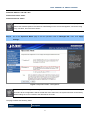
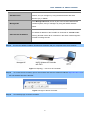
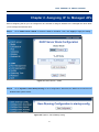
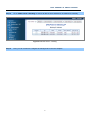
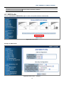
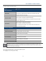
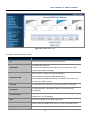
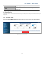
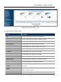
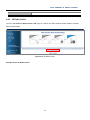
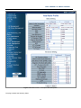
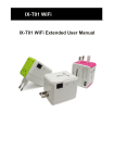
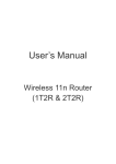
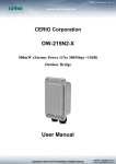
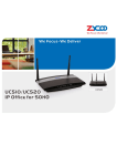
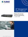
User Manual of WAPC-1232HP Copyright Copyright 2015 by PLANET Technology Corp. All rights reserved. No part of this publication may be reproduced, transmitted, transcribed, stored in a retrieval system, or translated into any language or computer language, in any form or by any means, electronic, mechanical, magnetic, optical, chemical, manual or otherwise, without the prior written permission of PLANET. PLANET makes no representations or warranties, either expressed or implied, with respect to the contents hereof and specifically disclaims any warranties, merchantability or fitness for any particular purpose. Any software described in this manual is sold or licensed "as is". Should the programs prove defective following their purchase, the buyer (and not PLANET, its distributor, or its dealer) assumes the entire cost of all necessary servicing, repair, and any incidental or consequential damages resulting from any defect in the software. Further, PLANET reserves the right to revise this publication and to make changes from time to time in the contents hereof without obligation to notify any person of such revision or changes. All brand and product names mentioned in this manual are trademarks and/or registered trademarks of their respective holders. Federal Communication Commission Interference Statement This equipment has been tested and found to comply with the limits for a Class B digital device, pursuant to Part 15 of FCC Rules. These limits are designed to provide reasonable protection against harmful interference in a residential installation. This equipment generates, uses, and can radiate radio frequency energy and, if not installed and used in accordance with the instructions, may cause harmful interference to radio communications. However, there is no guarantee that interference will not occur in a particular installation. If this equipment does cause harmful interference to radio or television reception, which can be determined by turning the equipment off and on, the user is encouraged to try to correct the interference by one or more of the following measures: 1. Reorient or relocate the receiving antenna. 2. Increase the separation between the equipment and receiver. 3. Connect the equipment into an outlet on a circuit different from that to which the receiver is connected. 4. Consult the dealer or an experienced radio technician for help. FCC Caution To assure continued compliance, use only shielded interface cables when connecting to computer or peripheral devices. Any changes or modifications not expressly approved by the party responsible for compliance could void the user’s authority to operate the equipment. This device complies with Part 15 of the FCC Rules. Operation is subject to the following two conditions: (1) This device may not cause harmful interference (2) This device must accept any interference received, including interference that may cause undesired operation. Any changes or modifications not expressly approved by the party responsible for compliance could void the user’s authority to operate the equipment. -II- User Manual of WAPC-1232HP Federal Communication Commission (FCC) Radiation Exposure Statement This equipment complies with FCC radiation exposure set forth for an uncontrolled environment. In order to avoid the possibility of exceeding the FCC radio frequency exposure limits, human proximity to the antenna shall not be less than 20 cm (8 inches) during normal operation. R&TTE Compliance Statement This equipment complies with all the requirements of DIRECTIVE 1999/5/CE OF THE EUROPEAN PARLIAMENT AND THE COUNCIL OF 9 March 1999 on radio equipment and telecommunication terminal Equipment and the mutual recognition of their conformity (R&TTE). The R&TTE Directive repeals and replaces in the directive 98/13/EEC (Telecommunications Terminal Equipment and Satellite Earth Station Equipment) as of April 8, 2000. Safety This equipment is designed with the utmost care for the safety of those who install and use it. However, special attention must be paid to the dangers of electric shock and static electricity when working with electrical equipment. All guidelines of this and of the computer manufacture must therefore be allowed at all times to ensure the safe use of the equipment. National Restrictions This device is intended for home and office use in all EU countries (and other countries following the EU directive 1999/5/EC) without any limitation except for the countries mentioned below: Country Restriction Bulgaria None Outdoor use; limited to 10 France mW e.i.r.p. within the band 2454-2483.5 MHz Italy None Luxembourg None Reasons/remarks General authorization required for outdoor use and public service Military Radiolocation use. Refarming of the 2.4 GHz band has been ongoing in recent years to allow current relaxed regulation. Full implementation planned 2012 If used outside of own premises, general authorization is required General authorization required for network and service supply(not for spectrum) This subsection does not apply for the Norway Implemented geographical area within a radius of 20 km from the centre of Ny-Ålesund Russian None Only for indoor applications Federation Note: Please don’t use the product outdoors in France. -III- User Manual of WAPC-1232HP WEEE regulation To avoid the potential effects on the environment and human health as a result of the presence of hazardous substances in electrical and electronic equipment, end users of electrical and electronic equipment should understand the meaning of the crossed-out wheeled bin symbol. Do not dispose of WEEE as unsorted municipal waste and have to collect such WEEE separately. Revision User Manual of PLANET Wireless AP Controller with 8-Port 802.3at PoE+ Model: WAPC-1232HP Rev: 1.0 (Sep., 2015) Part No. EM-WAPC-1232HP_v1.0 (2080- E70020-000) -IV- User Manual of WAPC-1232HP CONTENTS Chapter 1.Configuring the AP and Login the Controller ..................................................................................... 1 1.1 Operation Mode...................................................................................................................................... 1 Chapter 2.Assigning IP to Managed APs .............................................................................................................. 6 Chapter 3.Configuring the AP Controller .............................................................................................................. 8 Chapter 4.AP Control .............................................................................................................................................. 9 4.1 AP Search ............................................................................................................................................... 9 4.2 Device List ............................................................................................................................................ 10 4.3 SSID Profile .......................................................................................................................................... 12 4.4 Radio Profile ......................................................................................................................................... 15 4.5 4.6 4.4.1 2.4G Radio Profile ..................................................................................................................... 15 4.4.2 5G Radio Profile ........................................................................................................................ 21 AP Management ................................................................................................................................... 27 4.5.1 General Setting ......................................................................................................................... 28 4.5.2 2.4GHz Wi-Fi Setting ................................................................................................................. 30 4.5.3 5GHz Wi-Fi Setting .................................................................................................................... 32 AP Group Management ....................................................................................................................... 34 4.6.1 2.4GHz Wi-Fi Setting ................................................................................................................. 37 4.6.2 5GHz Wi-Fi Setting .................................................................................................................... 38 Chapter 5.AP Monitoring/AP Status ..................................................................................................................... 41 5.1 AP Status Summary ............................................................................................................................. 41 5.2 SSID Summary ..................................................................................................................................... 43 5.3 Radio Summary.................................................................................................................................... 44 5.4 AP Real Time Traffic ............................................................................................................................ 46 5.5 Active Clients ....................................................................................................................................... 47 5.6 Rogue AP List....................................................................................................................................... 49 Chapter 6.AP Maintenance ................................................................................................................................... 51 -V- User Manual of WAPC-1232HP 6.1 TFTP Setting ......................................................................................................................................... 51 6.2 Firmware Upgrade ............................................................................................................................... 54 6.3 Group Firmware Upgrade ................................................................................................................... 56 6.4 Reset AP ............................................................................................................................................... 57 6.5 LED Control .......................................................................................................................................... 58 -VI- User Manual of WAPC-1232HP FIGURES FIGURE 1-1 LOGIN BY DEFAULT IP ADDRESS................................................................................................................................... 1 FIGURE 1-2 LOGIN WINDOW .......................................................................................................................................................... 2 FIGURE 1-3 OPERATION MODE – MANAGED AP ............................................................................................................................. 3 FIGURE 1-4 TOPOLOGY – CONNECT TO AP CONTROLLER ............................................................................................................... 4 FIGURE 1-5 LOGIN TO THE AP CONTROLLER .................................................................................................................................. 4 FIGURE 1-6 AP CONTROLLER – MAIN ............................................................................................................................................ 5 FIGURE 2-1 DHCP SERVER – MODE ............................................................................................................................................... 6 FIGURE 2-2 SYSTEM – SAVE STARTUP CONFIG ............................................................................................................................... 6 FIGURE 2-3 DHCP SERVER – BINDING ........................................................................................................................................... 7 FIGURE 3-1 AP CONTROLLER – MENU ........................................................................................................................................... 8 FIGURE 4-1 MENU – AP CONTROL ................................................................................................................................................. 9 FIGURE 4-2 AP SEARCH ................................................................................................................................................................. 9 FIGURE 4-3 AP SEARCH – SELECT THE AP FROM THE LIST............................................................................................................ 10 FIGURE 4-4 DEVICE LIST .............................................................................................................................................................. 11 FIGURE 4-5 SSID PROFILE ........................................................................................................................................................... 12 FIGURE 4-6 SSID PROFILE – EXAMPLE ........................................................................................................................................ 12 FIGURE 4-7 SSID PROFILE – LIST ................................................................................................................................................ 14 FIGURE 4-8 2.4G RADIO PROFILE................................................................................................................................................. 15 FIGURE 4-9 RADIO PROFILE – EXAMPLE OF 2.4G RADIO PROFILE ................................................................................................. 16 FIGURE 4-10 2.4G RADIO PROFILE – LIST .................................................................................................................................... 20 FIGURE 4-11 5G RADIO PROFILE .................................................................................................................................................. 21 FIGURE 4-12 RADIO PROFILE – EXAMPLE OF 5G RADIO PROFILE .................................................................................................. 22 FIGURE 4-13 5G RADIO PROFILE – LIST ....................................................................................................................................... 26 FIGURE 4-14 AP MANAGEMENT – AP LIST................................................................................................................................... 27 FIGURE 4-15 AP MANAGEMENT - GENERAL SETTING .................................................................................................................. 29 FIGURE 4-16 AP MANAGEMENT – 2.4G WI-FI SETTING ............................................................................................................... 31 FIGURE 4-17 AP MANAGEMENT – 5G WI-FI SETTING .................................................................................................................. 33 FIGURE 4-18 AP GROUP MANAGEMENT ....................................................................................................................................... 34 FIGURE 4-19 AP GROUP MANAGEMENT - ADD A NEW AP GROUP ................................................................................................. 35 -VII- User Manual of WAPC-1232HP FIGURE 4-20 AP GROUP MANAGEMENT – GROUP LIST ................................................................................................................. 36 FIGURE 4-21 AP GROUP MANAGEMENT – 2.4G WI-FI SETTING ................................................................................................... 37 FIGURE 4-22 AP GROUP MANAGEMENT – 5G WI-FI SETTING ...................................................................................................... 39 FIGURE 5-1 MENU – AP MONITORING / AP STATUS...................................................................................................................... 41 FIGURE 5-2 AP MONITORING / AP STATUS – AP STATUS SUMMARY ............................................................................................. 41 FIGURE 5-3 AP MONITORING / AP STATUS – SSID SUMMARY...................................................................................................... 43 FIGURE 5-4 AP MONITORING / AP STATUS – RADIO SUMMARY.................................................................................................... 44 FIGURE 5-5 AP MONITORING / AP STATUS – AP REAL TIME TRAFFIC .......................................................................................... 46 FIGURE 5-6 AP MONITORING / AP STATUS – ACTIVE CLIENTS ..................................................................................................... 48 FIGURE 5-7 AP MONITORING / AP STATUS – ROGUE AP LIST ....................................................................................................... 49 FIGURE 6-1 MENU – AP MAINTENANCE ....................................................................................................................................... 51 FIGURE 6-2 AP MAINTENANCE - TFTP SETTING .......................................................................................................................... 51 FIGURE 6-3 TFTP SERVER SETTING – COPY FIRMWARE TO THE SERVER ........................................................................................ 52 FIGURE 6-4 TFTP SERVER SETTING – SET DIRECTORY AND IP....................................................................................................... 53 FIGURE 6-5 TFTP SERVER SETTING – LOCATE FIRMWARE AND CONFIGURE TFTP SERVER IP ....................................................... 53 FIGURE 6-6 TFTP SERVER SETTING – FINISH ................................................................................................................................ 54 FIGURE 6-7 FIRMWARE UPGRADE – SELECT THE AP..................................................................................................................... 54 FIGURE 6-8 FIRMWARE UPGRADE – START TO UPGRADE............................................................................................................... 54 FIGURE 6-9 AP MAINTENANCE – FIRMWARE UPGRADE ............................................................................................................... 55 FIGURE 6-10 AP MAINTENANCE – GROUP FIRMWARE UPGRADE ................................................................................................. 56 FIGURE 6-11 AP MAINTENANCE – RESET AP ............................................................................................................................... 57 FIGURE 6-12 AP MAINTENANCE – LED CONTROL ....................................................................................................................... 58 -VIII- User Manual of WAPC-1232HP Chapter 1. Configuring the AP and Login the Controller In this manual, we use the WDAP-C7200AC managed AP as an example to be controlled by the WAPC-1232HP Wireless AP Controller with 8-Port 802.3at PoE+. Before configuring the WDAP-C7200AC in the managed AP mode to be managed by the AP controller, please ensure you have upgraded the AP to the firmware that supports the AP controller. After the upgrade is finished, please go to the “Management-> Reload Settings” page to upload the latest config file included in the firmware package file. After the upload for the configuration is finished, please reset the AP to the factory default. 1.1 Operation Mode Follow the steps below to set up the operation mode of the WDAP-C7200AC in the “Managed AP” mode. Step 1. To access the WDAP-C7200AC, open a web-browser and enter the default IP address http://192.168.1.253 in the web address field of the browser. Figure 1-1 Login by default IP address After a moment, a login window will appear. Enter admin for the User Name and Password, both in lower case letters. Then click the OK button or press the Enter key. -1- User Manual of WAPC-1232HP Figure 1-2 Login Window -2- User Manual of WAPC-1232HP Default IP Address: 192.168.1.253 Default User Name: admin Default Password: admin If the above screen does not pop up, it may mean that your web-browser has been set to a proxy. Go to Tools menu>Internet Options>Connections>LAN Settings on the screen that appears, cancel the Using Proxy checkbox, and click OK to finish it. Step 2. Go to the “Operation Mode” page to set the operation mode to “Managed AP”. Then, click “Apply Change”. Figure 1-3 Operation Mode – Managed AP Please back up the configuration settings before switching from the Standalone AP mode to the Managed AP mode. All the configurations will be erased and at the same time, the system will return to the factory default settings once it is reverted to the Standalone AP mode. The page includes the following fields: Object Description -3- User Manual of WAPC-1232HP In the Standalone AP mode, the AP acts as an individual AP in the Standalone AP network, and you manage it by using the Administrator Web User Interface (UI), or SNMP. In the Managed AP mode, the AP is part of the PLANET Wireless AP Managed AP controller System, and you manage it by using the WAPC Wireless Switch. IP address of the AP Controller. (Default = 0.0.0.0) The default IP address of the PLANET AP Controller is “192.168.1.100”. AP Controller IP Address Entering “0.0.0.0” means all AP controllers in the same network segment are able to manage this AP. Step 3. Connect the WDAP-C7200AC, Wireless AP Controller and your computer to the same network. Figure 1-4 Topology – connect to AP Controller Step 4. To access the AP controller, open a web browser and enter the default IP address http://192.168.1.100 in the web address field of the browser. Figure 1-5 Login to the AP Controller Step 5. Successfully login to the AP controller. -4- User Manual of WAPC-1232HP Figure 1-6 AP Controller – Main -5- User Manual of WAPC-1232HP Chapter 2. Assigning IP to Managed APs Before configuring the AP, you can configure the AP controller to assign IP address to the managed APs which allow you to manage the APs with ease. Step 1. Go to “DHCP server-> Mode” to switch the Mode to “Enabled”. Then, click “Apply” to apply the setting. Figure 2-1 DHCP Server – Mode Step 2. Go to “System-> Save Startup Config” to save configuration. Otherwise, the DHCP server will return to disabled after system reboot. Figure 2-2 System – Save Startup Config -6- User Manual of WAPC-1232HP Step 3. Go to “DHCP server-> Binding” to ensure all devices have obtained an IP address successfully. Figure 2-3 DHCP Server – Binding Step 4. Now, you can continue to configure the managed AP in the next chapters. -7- User Manual of WAPC-1232HP Chapter 3. Configuring the AP Controller This chapter delivers a detailed presentation of AP Controller’s functionalities and features under 3 main menus including AP Control, AP Monitoring/AP Status and AP Maintenance, allowing you to manage the AP with ease. Figure 3-1 AP Controller – Menu -8- User Manual of WAPC-1232HP Chapter 4. AP Control In the AP Control section, there are six sub menus which make you able to discover AP, create profile, and upload the pre-defined profiles to single or multiple APs at once. Figure 4-1 Menu – AP Control 4.1 AP Search Go to the “AP Control-> AP Search” page and then click “Refresh” to discover the managed AP available in the network. Only the AP existed in the same network segment can be discovered and added to the device list of controller. A maximum of 64 devices can be found on the AP Search page. Figure 4-2 AP Search -9- User Manual of WAPC-1232HP In the “Select Device” field, check the AP that you want to manage and then click “Apply”. Figure 4-3 AP Search – select the AP from the list The page includes the following fields: Object Description ID This field represents the numerical order of device. MAC Address The MAC address of the AP AP Model The model name of the AP Version The current firmware version of the AP Device IP The IP address of the AP Device Netmask The netmask of the AP Device Gateway The gateway IP address of the AP Device Description The device description of the AP Select Device Check this option to select the device from the managed AP list. Auto Refresh Check this option to let the system automatically refresh the list every 15 seconds. Refresh Click this button to refresh the list manually. Apply Click this button to apply the settings. 4.2 Device List Go to the “AP Control-> Device List” page to ensure the AP is already selected from the list. This section is to confirm the AP selected on the “AP Search” page has been added to the Device List Table so that we can control it -10- User Manual of WAPC-1232HP by the following sections. On this page, you can click the hyperlink of IP address to link to the AP’s Web UI directly. In addition, if this device is not the AP that you want to manage, you can check it in the delete field to remove it from the list. A maximum of 32 devices can be added on the Device List page. Figure 4-4 Device List The page includes the following fields: Object Description ID This field represents the numerical order of device. MAC Address The MAC address of the AP AP Model The model name of the AP Version The current firmware version of the AP The IP address of the AP Device IP On the Device List page, the IP address is a hyperlink which enables the user to link to the AP’s Web configuration page directly. Device Netmask The netmask of the AP Device Gateway The gateway IP address of the AP Device Description The device description of the AP Delete Check this option to remove the device from the managed AP list. Auto Refresh Check this option to let the system automatically refresh the list every 15 seconds. Refresh Click this button to refresh the list manually. -11- User Manual of WAPC-1232HP Apply Click this button to apply the settings. 4.3 SSID Profile Go to the “AP Control-> SSID Profile” page to create a new profile related to wireless SSID. Figure 4-5 SSID Profile Example of SSID Profile: Figure 4-6 SSID Profile – Example -12- User Manual of WAPC-1232HP The page includes the following fields: Object Description SSID Configuration This SSID name of the AP SSID Name The length of an SSID should be limited to 32 characters (32 octets, normally ASCII letters and digits). Select “Enable” to enable the SSID Broadcasting. Broadcast SSID Select “Disable” to disable the SSID Broadcasting. Once disabling the SSID Broadcasting, the wireless clients will not able to see the SSID of the AP. Select “Enable” to enable the AP Isolation. AP Isolation Select “Disable” to disable the AP Isolation. Once enabling the AP Isolation, the wireless clients connected to the same SSID will be isolated. Security Configuration Encryption The encryption of the SSID Authentication Mode The authentication mode of the SSID WPA2 Cipher Suite The cipher suite of the encryption Pre-shared Key Format The security key format of the SSID Pre-shared Key The security key of the SSID Save Save the settings as a new profile. Reset Reset the values to default. The fields on the Security Configuration page will vary according to the encryption you select. For a detailed description of each field, you may refer to the user manual of the AP. In this section, only the definitions of the fields are described. After creating the SSID profile, you will see the profile in the list. Click “Apply” to save and apply the setting. -13- User Manual of WAPC-1232HP Figure 4-7 SSID Profile – List The page includes the following fields: Object ID Description This field represents the numerical order of device. This SSID name of the AP SSID Name The length of an SSID should be limited to 32 characters (32 octets, normally ASCII letters and digits). Select “Enable” to enable the SSID Broadcasting. Broadcast SSID Select “Disable” to disable the SSID Broadcasting. Once disabling the SSID Broadcasting, the wireless clients will not be able to see the SSID of the AP. Security Encryption This field equals the “Encryption” field of the Security Configuration. This field equals the “Authentication Mode” field of the Security Configuration. Client Isolation Displays the setting of the client isolation which is to be configured by enabling it or not to by disabling. Edit Click “Edit” hyperlink to re-configure the profile. Add New SSID Profile Click the “Add New SSID Profile” button to create a new SSID profile. Apply In the delete field, check the profile that you want to delete and click -14- User Manual of WAPC-1232HP “Apply” to apply the setting. Reset Click “Reset” to cancel the check box of the delete option back to uncheck status. 4.4 Radio Profile In this section, you can create wireless advanced settings as 2.4GHz profile or 5GHz profile for future provisioning to multiple APs. 4.4.1 2.4G Radio Profile Go to the “AP Control-> Radio Profile-> 2.4G” page to create a new 2.4GHz wireless profile related to wireless advance parameters. Figure 4-8 2.4G Radio Profile -15- User Manual of WAPC-1232HP Example of the 2.4G Radio Profile: Figure 4-9 Radio Profile – example of 2.4G radio profile The page includes the following fields: -16- User Manual of WAPC-1232HP Object Description Basic Setting Radio Profile Description Enter the name of the profile Channel The operating frequency of the wireless network. The default is “Auto”. Network Mode The network mode of the wireless interface Mixed Mode work in 802.11b/g/n mode; Green Field operates only in Operation Mode 802.11n mode and is not compatible with legacy mode (802.11b/g mode). Default is “Mixed”. When enabling Reverse Direction Grant, the wireless AP can reduce the transmitted data packet collision by using the Reverse Direction Protocol. RDG During TXOP (Transmission Opportunity) period, the receiver could use the remaining transmission time to transmit data to a sender. The RDG improves transmission performance and scalability in a wireless environment. Default is “Disabled”. A mechanism that allows a unit with only one antenna to leverage STBC multiple antennas on other 802.11n devices to improve performance and range. Default is “Disabled”. An aggregation technique which prevents sending Ack in the Auto Block Ack communication to reduce the network congestion. If this option is enabled, the device will try to activate this function when transmitting massive data. Default is “Disabled”. Decline BA Request Enable this option to decline the Block Ack request addressed by the other devices. Default is “Disabled”. HT Disallow TKIP Prevents the use of TKIP data encryption when using 802.11n high throughput data rates. Default is “Disabled”. Channel Bandwidth The channel bandwidth of the 2.4GHz wireless interface. Default is “40”. Guard intervals are used to ensure that distinct transmissions do not Guard Interval interfere with one another. Only effective under Mixed Mode. Default is “Long”. The Modulation and Coding Scheme (MCS) is a value that determines MCS the modulation, coding and number of spatial channels. Default is “Auto”. -17- User Manual of WAPC-1232HP HT means High Throughput. The number of HT TxStream means HT Tx Stream how many antennas will transmit data simultaneously. (Options: 1 or 2) Default is “2”. The number of HT RxStream means how many antennas will HT Rx Stream receive data simultaneously. (Option: 1 or 2) Default is “2”. You can adjust the wireless transmit power here. By reducing the TX Tx Power power, you can reduce the wireless coverage to make it only cover the area you need. Default is “100”. Advanced Setting In IEEE802.11b/g mixed environment, IEEE802.11g has priority over IEEE802.11b on the connection. BG Protection Mode Auto: STA will dynamically change to AP announcement. On: IEEE802.11g is used first on the connection. Off: In IEEE802.11b/g mixed environment, take slower conditions. Default is "Auto". Beacon Interval (20-1024 ms) The interval of time that this access point broadcasts a beacon. Beacon is used to synchronize the wireless network. Default is “100”. This is the Delivery Traffic Indication Map. It is used to alert the clients Data Beacon Rate (DTIM) that multicast and broadcast packets buffered at the AP will be (1-255) transmitted immediately after the transmission of this beacon frame. Default is “1”; if not supported, it will display “0”. Fragment Threshold (256-2346) You can specify the maximum size of packet during the fragmentation of data to be transmitted. If you set this value too low, it will result in bad performance. Default is “2346”. When the packet size is smaller than the RTS threshold, the access point RTS Threshold (0-2347) will not use the RTS/CTS mechanism to send this packet. Default is “2347”. The “Long Preamble” can provide better wireless LAN compatibility while Short Preamble the “Short Preamble” can provide better wireless LAN performance. Default is “Disabled” (Long Preamble). Calculating the standby time before transmitting data, set up the base Short Slot time for the wireless AP. If you enable the Short Slot, it can increase performance (if you only expect 802.11g traffic). 802.11b is not -18- User Manual of WAPC-1232HP compatible with short slot time. Default is “Enabled”. A performance enhancement that transmits a number of data packets at Tx Burst the same time when the feature is supported by compatible clients. Default is “Enabled”. Pkt Aggregate A performance enhancement that combines data packets together when the feature is supported by compatible clients. Default is “Enabled” WMM Capable Provide the basic quality on the wireless network complied with IEEE 802.11. Default is “Enabled”. APSD function is used for controlling power consumption. APSD enables APSD Capable the Beacon interval at longer distance until the traffic reaches at the specified point. Default is “Disabled”. Direct Link Setting (DLS) enables all clients’ data to be transmitted DLS Capable effectively. If DSL is enabled, the wireless LAN router performs establishing the connection of all the clients at this unit and speeding up of data transmission. Default is “Disabled”. Multicast-to-Unicast Convert Multicast data to Unicast one. Default is “Enabled”. IAPP (Inter-Access Point Protocol) enabled is recommended as it IAPP describes an optional extension to IEEE 802.11 that provides wireless access-point communications among multi-vendor systems. Default is “Disabled”. Enabling TX Beamforming focuses the AP’s energy toward a client. It increases the performance of wireless networks at medium ranges. At TX Beamforming short ranges, the signal power is high enough that the SNR will support the maximum data rate. At long ranges, beamforming does not offer a substantial gain over an omnidirectional antenna, and data rates will be identical to non-beamformed transmissions. Default is “Enabled”. Apply Save and apply the settings as a new profile. Reset Reset the values to default. After creating the 2.4GHz radio profile, you will see the profile in the list. Click “Apply” to save and apply the setting. -19- User Manual of WAPC-1232HP Figure 4-10 2.4G Radio Profile – List The page includes the following fields: Object Description ID This field represents the numerical order of device. Delete Check this option and click “Apply” to delete the profile. Radio Profile Description This field displays the description of the profile. Network Mode This field displays the network mode of the profile. Channel ID This field displays the channel number of the profile. Channel Bandwidth This field displays the channel bandwidth of the profile. Tx Power This field displays the Tx power of the profile. Data Rate This field displays the data rate of the profile. IAPP This field displays the IAPP that is enabled or disabled. WMM Capable This field displays the WMM that is enabled or disabled. Edit Click “Edit” hyperlink to re-configure the profile. Add New 2.4GHz Radio Click the “Add New 2.4GHz Radio Profile” button to create a new 2.4G Profile radio profile. Apply In the delete field, check the profile that you want to delete and click “Apply” to apply the setting. Reset Click “Reset” to cancel the check box of the delete option back to -20- User Manual of WAPC-1232HP uncheck status. 4.4.2 5G Radio Profile Go to the “AP Control-> Radio Profile-> 5G” page to create a new 5GHz wireless profile related to wireless advance parameters. Figure 4-11 5G Radio Profile Example of the 5G Radio Profile: -21- User Manual of WAPC-1232HP Figure 4-12 Radio Profile – example of 5G radio profile The page includes the following fields: -22- User Manual of WAPC-1232HP Object Description Basic Setting Radio Profile Description Enter the name of the profile. Channel The operating frequency of the wireless network. The default is “Auto”. Network Mode The network mode of the wireless interface Mixed Mode work in 802.11b/g/n mode; Green Field operates only in 802.11n mode and will not compatible with legacy mode (802.11b/g Operation Mode mode). Default is “Mixed”. This field only supports in 2.4GHz frequency band. When enabling Reverse Direction Grant, the wireless AP can reduce the transmitted data packet collision by using the Reverse Direction Protocol. RDG During TXOP (Transmission Opportunity) period, the receiver could use the remaining transmission time to transmit data to a sender. The RDG improves transmission performance and scalability in a wireless environment. Default is “Disabled”. A mechanism that allows a unit with only one antenna to leverage STBC multiple antennas on other 802.11n devices to improve performance and range. Default is “Disabled”. An aggregation technique which prevents sending Ack in the Auto Block Ack communication to reduce the network congestion. If this option is enabled, the device will try to activate this function when transmitting massive data. Default is “Disabled”. Decline BA Request Enable this option to decline the Block Ack request addressed by the other devices. Default is “Disabled”. HT Disallow TKIP Prevents the use of TKIP data encryption when using 802.11n high throughput data rates. Default is “Disabled”. Channel Bandwidth The channel bandwidth of the 5GHz wireless interface. Default is “80”. Guard intervals are used to ensure that distinct transmissions do not Guard Interval interfere with one another. Only effective under Mixed Mode. Default is “Long”. MCS The Modulation and Coding Scheme (MCS) is a value that determines -23- User Manual of WAPC-1232HP the modulation, coding and number of spatial channels. Default is “Auto”. HT means High Throughput. The number of HT TxStream means HT Tx Stream how many antennas will transmit data simultaneously. (Option: 1 or 2) Default is “2”. The number of HT RxStream means how many antennas will HT Rx Stream receive data simultaneously. (Option: 1 or 2) Default is “2”. You can adjust the wireless transmit power here. By reducing the TX Tx Power power, you can reduce the wireless coverage to make it only cover the area you need. Default is “100”. Advanced Setting In IEEE802.11b/g mixed environment, IEEE802.11g has priority over IEEE802.11b on the connection. Auto: STA will dynamically change to AP announcement. BG Protection Mode On: IEEE802.11g is used first on the connection. Off: In IEEE802.11b/g mixed environment, take slower conditions. Default is "Auto". This field only supports in 2.4GHz frequency band. Beacon Interval (20-1024 ms) The interval of time that this access point broadcasts a beacon. Beacon is used to synchronize the wireless network. Default is “100”. This is the Delivery Traffic Indication Map. It is used to alert the clients Data Beacon Rate (DTIM) that multicast and broadcast packets buffered at the AP will be (1-255) transmitted immediately after the transmission of this beacon frame. Default is “1”; if not supported, it will display “0”. Fragment Threshold (256-2346) You can specify the maximum size of packet during the fragmentation of data to be transmitted. If you set this value too low, it will result in bad performance. Default is “2346”. When the packet size is smaller than the RTS threshold, the access point RTS Threshold (0-2347) will not use the RTS/CTS mechanism to send this packet. Default is “2347”. The “Long Preamble” can provide better wireless LAN compatibility while Short Preamble the “Short Preamble” can provide better wireless LAN performance. Default is “Disabled” (Long Preamble). -24- User Manual of WAPC-1232HP Calculating the standby time before transmitting data, set up the base Short Slot time for the wireless AP. If you enable the Short Slot, it can increase performance (if you only expect 802.11g traffic). 802.11b is not compatible with short slot time. Default is “Enabled”. A performance enhancement that transmits a number of data packets at Tx Burst the same time when the feature is supported by compatible clients. Default is “Enabled”. Pkt Aggregate A performance enhancement that combines data packets together when the feature is supported by compatible clients. Default is “Enabled” WMM Capable Provide the basic quality on the wireless network complied with IEEE 802.11. Default is “Enabled”. APSD function is used for controlling power consumption. APSD enables APSD Capable the Beacon interval at longer distance until the traffic reaches at the specified point. Default is “Disabled”. Direct Link Setting (DLS) enables all clients’ data to be transmitted DLS Capable effectively. If DSL is enabled, the wireless LAN router performs establishing the connection of all the clients at this unit and speeding up of data transmission. Default is “Disabled”. Multicast-to-Unicast Convert Multicast data to Unicast one. Default is “Enabled”. IAPP (Inter-Access Point Protocol) enabled is recommended as it IAPP describes an optional extension to IEEE 802.11 that provides wireless access-point communications among multivendor systems. Default is “Disabled”. Enable TX Beamforming focuses the AP’s energy toward a client. It increases the performance of wireless networks at medium ranges. At TX Beamforming short ranges, the signal power is high enough that the SNR will support the maximum data rate. At long ranges, beamforming does not offer a substantial gain over an omnidirectional antenna, and data rates will be identical to non-beamformed transmissions. Default is “Enabled”. Apply Save and apply the settings as a new profile. Reset Reset the values to default. After creating the 5GHz radio profile, you will see the profile in the list. Click “Apply” to save and apply the setting. -25- User Manual of WAPC-1232HP Figure 4-13 5G Radio Profile – List The page includes the following fields: Object Description ID This field represents the numerical order of device. Delete Check this option and click “Apply” to delete the profile. Radio Profile Description This field displays the description of the profile. Network Mode This field displays the network mode of the profile. Channel ID This field displays the channel number of the profile. Channel Bandwidth This field displays the channel bandwidth of the profile. Tx Power This field displays the Tx power of the profile. Data Rate This field displays the data rate of the profile. IAPP This field displays the IAPP that is enabled or disabled. WMM Capable This field displays the WMM that is enabled or disabled. Edit Click “Edit” hyperlink to re-configure the profile. Add New 5GHz Radio Click “Add New 5GHz Radio Profile” button to create a new 5G radio Profile profile. Apply In the delete field, check the profile that you want to delete and click “Apply” to apply the setting. Reset Click “Reset” to cancel the check box of the delete option back to -26- User Manual of WAPC-1232HP uncheck status. 4.5 AP Management Go to the “AP Control-> AP Management” page to configure the wireless setting for each managed AP. Figure 4-14 AP Management – AP List The page includes the following fields: Object Description Use one and multiple filtering rules to query the AP and click “Refresh” to execute the query. Status: Check this option and filter the AP list by the AP status online or offline. Query by AP Model: Check this option and filter the AP list by the AP Model that user specifies. MAC Address: Check this option and filter the AP list by the MAC address that user specifies. AP Group: check this option and filter the AP list by the group that user specifies. ID This field represents the numerical order of device. Online: the AP is online Status Offline: the AP is offline Wireless Disable: the 2.4G & 5G wireless signals are both disabled -27- User Manual of WAPC-1232HP Model The model name of the AP Device IP The IP address of the AP MAC Address The MAC address of the AP The device description of the AP Device Description This field can be modified through the “Setting” hyperlink under the sub-item “General Setting”. If the AP has been added to a group, the “General Setting”, “2.4GHz Wi-Fi AP Group Setting” and “5GHz Wi-Fi Setting” will be disabled; user must go to the AP Group Management page to configure this through its group. Remove General Setting Check this option and click “Apply” to remove the AP from the list. Click the “Setting” hyperlink to edit and apply the new general setting including the AP description and TCP/IP setting. 2.4GHz Wi-Fi Setting Click the “Setting” hyperlink to apply the 2.4GHz SSID and Radio profiles to the AP. 5GHz Wi-Fi Setting Click the “Setting” hyperlink to apply the 5GHz SSID and Radio profiles to the AP. Auto-refresh Check this option to let the system refresh the AP list every 15 seconds automatically. Refresh Apply Click "Refresh" to query or update the current list. Click "Apply" to save and apply the setting; the setting will take effect after about 60 seconds. Reset Click “Reset” to cancel the check box of the remove option back to uncheck status. 4.5.1 General Setting Click the “Setting” hyperlink under the “General Setting” field to enter the sub-menu of AP Management. On this page, you can edit and apply the new general setting including the AP description and TCP/IP setting. -28- User Manual of WAPC-1232HP Figure 4-15 AP Management - General Setting The page includes the following fields: Object Description AP Information AP Model The model name of the AP AP MAC The MAC address of the AP AP Description The device description of the AP This field length is limited to 32 characters. System Uptime The system bootup time AP LAN Setting -29- User Manual of WAPC-1232HP This field is used to enable or disable DHCP Server of the AP. Static: Choose this option to configure the static IP address for the AP. DHCP Mode DHCP Client: Choose this option to obtain the IP address from the DHCP Server for the AP. DHCP Server: Choose this option to assign the IP address to the wireless clients for the AP. Device IP This field is used to set the IP address of the AP when the DHCP Mode is changed to “Static”. Device Mask This field is used to set the net mask of the AP when the DHCP Mode is changed to “Static”. Device Gateway This field is used to set the Gateway IP address of the AP when the DHCP Mode is changed to “Static”. DNS Server This field is used to set the DNS Server of the AP. NTP Server This field is used to set the NTP Server of the AP. UPNP Enable This field is used to enable or disable UPNP option of the AP. Apply Click "Apply" to save and apply the setting. Reset Click “Reset” to erase all settings to default values. 4.5.2 2.4GHz Wi-Fi Setting Click the “Setting” hyperlink under the “2.4GHz Wi-Fi Setting” field to enter the sub-menu of AP Management. On this page, you can designate the AP to use the specific 2.4GHz SSID and Radio profiles. -30- User Manual of WAPC-1232HP d Figure 4-16 AP Management – 2.4G Wi-Fi Setting The page includes the following fields: Object Description AP Information AP Model The model name of the AP AP MAC The MAC address of the AP AP Description The device description of the AP. To edit this field, please go to the “General Setting” page. AP IP Address This IP address of the AP -31- User Manual of WAPC-1232HP 2.4GHz SSID Configuration SSID 1 This field is used to designate the 2.4GHz SSID Profile to the AP’s 2.4GHz SSID-1. To create new SSID profile, please go to the SSID Profile page. SSID 2 This field is used to designate the 2.4GHz SSID Profile to the AP’s 2.4GHz SSID-2. To create new SSID profile, please go to the SSID Profile page. SSID 3 This field is used to designate the 2.4GHz SSID Profile to the AP’s 2.4GHz SSID-3. To create new SSID profile, please go to the SSID Profile page. SSID 4 This field is used to designate the 2.4GHz SSID Profile to the AP’s 2.4GHz SSID-4. To create new SSID profile, please go to the SSID Profile page. SSID 5 This field is used to designate the 2.4GHz SSID Profile to the AP’s 2.4GHz SSID-5. To create new SSID profile, please go to the SSID Profile page. 2.4GHz Radio Configuration This field is used to designate the 2.4GHz Radio Profile to the AP’s 2.4GHz Radio Profile advanced setting. To create new 2.4GHz radio profile, please go to the “Radio Profile-> 2.4G” page. Apply Click "Apply" to save and apply the setting. Reset Click “Reset” to erase all settings to default values. 4.5.3 5GHz Wi-Fi Setting Click the “Setting” hyperlink under the “5GHz Wi-Fi Setting” field to enter the sub-menu of AP Management. On this page, you can designate the AP to use the specific 5GHz SSID and Radio profiles. -32- User Manual of WAPC-1232HP Figure 4-17 AP Management – 5G Wi-Fi Setting The page includes the following fields: Object Description AP Information AP Model The model name of the AP AP MAC The MAC address of the AP AP Description The device description of the AP. To edit this field, please go to the “General Setting” page. AP IP Address This IP address of the AP -33- User Manual of WAPC-1232HP 5GHz SSID Configuration SSID 1 This field is used to designate the 5GHz SSID Profile to the AP’s 5GHz SSID-1. To create new SSID profile, please go to the SSID Profile page. SSID 2 This field is used to designate the 5GHz SSID Profile to the AP’s 5GHz SSID-2. To create new SSID profile, please go to the SSID Profile page. SSID 3 This field is used to designate the 5GHz SSID Profile to the AP’s 5GHz SSID-3. To create new SSID profile, please go to the SSID Profile page. SSID 4 This field is used to designate the 5GHz SSID Profile to the AP’s 5GHz SSID-4. To create new SSID profile, please go to the SSID Profile page. SSID 5 This field is used to designate the 5GHz SSID Profile to the AP’s 5GHz SSID-5. To create new SSID profile, please go to the SSID Profile page. 5GHz Radio Configuration This field is used to designate the 5GHz Radio Profile to the AP’s 5GHz Radio Profile advanced setting. To create new 5GHz radio profile, please go to the “Radio Profile-> 5G” page. Apply Click "Apply" to save and apply the setting. Reset Click “Reset” to erase all settings to default values. 4.6 AP Group Management Go to the “AP Control-> AP Group Management” page to create a new AP group and then configure the wireless setting by group. Click “Add Group Profile” to add the new AP group. Figure 4-18 AP Group Management -34- User Manual of WAPC-1232HP Figure 4-19 AP Group Management - add a new AP group The page includes the following fields: Object Description AP Group Setting AP Group Name The AP group name The field length is limited to 16 characters. AP Group Description The description of the AP group The field length is limited to 16 characters. The model name of the AP AP Model Name Only the same model of the AP can be created as a group to prevent any wireless parameters from inconsistency caused by the provisioning failure. AP Group Member Setting Current AP Group Members Available Managed APs This section displays the members in this AP group. This section displays the APs conforming to user selected model, and is available for grouping. Remove >> Highlight the current AP and click “Remove >>” to remove it from the group. -35- User Manual of WAPC-1232HP << Add Highlight the available AP and click “<< Add” to add it to the group. Apply Click “Apply” to save and apply the settings. Reset Click “Reset” to erase all settings. Figure 4-20 AP Group Management – group list The page includes the following fields: Object ID Enable Description This field represents the numerical order of device. Check the group that you want to upload the new setting and click “Apply” to take effect. Group Name This field displays the group name. Group Description This field displays the group description. Delete Check the group that you want to delete and click “Apply” to delete the group. AP Member Setting 2.4GHz Wi-Fi Setting Click “Edit” to edit the group. Click the “Setting” hyperlink to apply the 2.4GHz SSID and Radio profiles to the AP group. 5GHz Wi-Fi Setting Click the “Setting” hyperlink to apply the 5GHz SSID and Radio profiles to the AP group. Click the “Apply” button to let the following behaviors take effect. Apply 1. In the Enable field, check the group that you want to upload the new setting and click “Apply” to take effect. 2. In the Delete field, check the group that you want to delete and click -36- User Manual of WAPC-1232HP “Apply” to delete the group. Reset Click “Reset” to cancel any check box back to uncheck status. 4.6.1 2.4GHz Wi-Fi Setting Click the “Setting” hyperlink under the “2.4GHz Wi-Fi Setting” field to enter the sub-menu of AP Group Management. On this page, you can designate the AP group to use the specific 2.4GHz SSID and Radio profiles. Figure 4-21 AP Group Management – 2.4G Wi-Fi Setting The page includes the following fields: Object Description AP Information AP Group Name The AP group name To edit this field, please go back to the “AP Member Setting” page. AP Group Description The description of the AP group. To edit this field, please go back to the “AP Member Setting” page. -37- User Manual of WAPC-1232HP 2.4GHz SSID Configuration SSID 1 This field is used to designate the 2.4GHz SSID Profile to the AP’s 2.4GHz SSID-1. To create new SSID profile, please go to the SSID Profile page. SSID 2 This field is used to designate the 2.4GHz SSID Profile to the AP’s 2.4GHz SSID-2. To create new SSID profile, please go to the SSID Profile page. SSID 3 This field is used to designate the 2.4GHz SSID Profile to the AP’s 2.4GHz SSID-3. To create new SSID profile, please go to the SSID Profile page. SSID 4 This field is used to designate the 2.4GHz SSID Profile to the AP’s 2.4GHz SSID-4. To create new SSID profile, please go to the SSID Profile page. SSID 5 This field is used to designate the 2.4GHz SSID Profile to the AP’s 2.4GHz SSID-5. To create new SSID profile, please go to the SSID Profile page. 2.4GHz Radio Configuration This field is used to designate the 2.4GHz Radio Profile to the AP’s 2.4GHz Radio Profile advanced setting. To create new 2.4GHz radio profile, please go to “Radio Profile-> 2.4G” page. Apply Click "Apply" to save and apply the setting. Reset Click “Reset” to erase all settings to default values. 4.6.2 5GHz Wi-Fi Setting Click the “Setting” hyperlink under the “5GHz Wi-Fi Setting” field to enter the sub-menu of AP Group Management. On this page, you can designate the AP group to use the specific 5GHz SSID and Radio profiles. -38- User Manual of WAPC-1232HP Figure 4-22 AP Group Management – 5G Wi-Fi Setting The page includes the following fields: Object Description AP Information AP Group Name The AP group name To edit this field, please go back to the “AP Member Setting” page. AP Group Description The description of the AP group To edit this field, please go back to the “AP Member Setting” page. 5GHz SSID Configuration SSID 1 This field is used to designate the 5GHz SSID Profile to the AP’s 5GHz SSID-1. To create new SSID profile, please go to the SSID Profile page. SSID 2 This field is used to designate the 5GHz SSID Profile to the AP’s 5GHz SSID-2. To create new SSID profile, please go to the SSID Profile page. SSID 3 This field is used to designate the 5GHz SSID Profile to the AP’s 5GHz SSID-3. To create new SSID profile, please go to the SSID Profile page. -39- User Manual of WAPC-1232HP SSID 4 This field is used to designate the 5GHz SSID Profile to the AP’s 5GHz SSID-4. To create new SSID profile, please go to the SSID Profile page. SSID 5 This field is used to designate the 5GHz SSID Profile to the AP’s 5GHz SSID-5. To create new SSID profile, please go to the SSID Profile page. 5GHz Radio Configuration This field is used to designate the 5GHz Radio Profile to the AP’s 5GHz Radio Profile advanced setting. To create new 5GHz radio profile, please go to the “Radio Profile-> 5G” page. Apply Click "Apply" to save and apply the setting. Reset Click “Reset” to erase all settings to default values. -40- User Manual of WAPC-1232HP Chapter 5. AP Monitoring/AP Status In the AP Monitoring section, there are six sub menus which make you able to observe the current status of single or multiple APs at once. Figure 5-1 Menu – AP Monitoring/AP Status 5.1 AP Status Summary Go to “AP Monitoring/AP Status-> AP Status Summary” to check the status of the managed APs in the Device List. Figure 5-2 AP Monitoring/AP Status – AP Status Summary The page includes the following fields: Object Query by Description Use one and multiple filtering rules to query the AP and click “Refresh” to execute the query. -41- User Manual of WAPC-1232HP Status: Check this option and filter the AP list by the AP status online or offline. AP Model: Check this option and filter the AP list by the AP Model that user specifies. AP MAC Address: Check this option and filter the AP list by the MAC address that user specifies. AP IP Address: Check this option and filter the AP list by the IP address that user specifies. ID This field represents the numerical order of device. Online: the AP is online Status Offline: the AP is offline Wireless Disable: the 2.4G & 5G wireless signals are both disabled MAC Address The MAC address of the AP Model The model name of the AP The device description of the AP Device Description This field can be modified through the “Setting” hyperlink under the sub-item “General Setting”. Device IP The IP address of the AP Firmware Version The current firmware version of the AP. AP Group The AP group number of the AP 2.4GHz: display the current 2.4G SSID profile that has been applied to this SSID Profile AP. 5GHz: display the current 5G SSID profile that has been applied to this AP. ※ If no profile has been applied to the AP, it will not display any value. 2.4GHz: display the current 2.4G Radio profile that has been applied to this Radio Profile AP. 5GHz: display the current 5G Radio profile that has been applied to this AP. ※ If no profile has been applied to the AP, it will not display any value. Auto-refresh Check this option to let the system refresh the AP list every 15 seconds automatically. Refresh Click "Refresh" to query or update the current list. -42- User Manual of WAPC-1232HP 5.2 SSID Summary Go to “AP Monitoring/AP Status-> SSID Summary” to check each SSID configuration status of the managed APs in the Device List. Figure 5-3 AP Monitoring/AP Status – SSID Summary The page includes the following fields: Object Description Use one and multiple filtering rules to query the AP and click “Refresh” to execute the query. AP Model: Check this option and filter the AP list by the AP model that user specifies. Query by AP MAC Address: Check this option and filter the AP list by the MAC address that user specifies. SSID: Check this option and filter the AP list by the SSID name that user specifies. Band: Check this option and filter the AP list by the frequency band that user specifies. ID This field represents the numerical order of device. AP MAC Address The MAC address of the AP AP Model The model name of the AP Device Description The device description of the AP This field can be modified through the “Setting” hyperlink under the sub-item -43- User Manual of WAPC-1232HP “General Setting”. Band The frequency band of the AP SSID The SSID name of the AP Channel Number The channel number of the AP Encryption The encryption of the AP BSSID The basic service set identification (BSSID) of this VAP. Associated Clients The client number associated to this VAP. SSID Broadcast Displays the SSID Broadcast option that is enabled or disabled in this VAP. Check this option to let the system refresh the AP list every 15 seconds Auto-refresh automatically. Refresh Click "Refresh" to query or update the current list. 5.3 Radio Summary Go to “AP Monitoring / AP Status-> Radio Summary” to check each Radio configuration status of the managed APs in the Device List. Figure 5-4 AP Monitoring/AP Status – Radio Summary The page includes the following fields: -44- User Manual of WAPC-1232HP Object Description Use one and multiple filtering rules to query the AP and click “Refresh” to execute the query. AP Model: Check this option and filter the AP list by the AP model that user specifies. Query by AP MAC Address: Check this option and filter the AP list by the MAC address that user specifies. Frequency Band: Check this option and filter the AP list by the frequency band that user specifies. Radio Profile: Check this option and filter the AP list by the radio profile name that user specifies. ID This field represents the numerical order of device. AP MAC Address The MAC address of the AP AP Model The model name of the AP The device description of the AP Device Description This field can be modified through the “Setting” hyperlink under the sub-item “General Setting”. Frequency Band The frequency band of the AP Radio Profile Description The radio profile description of the AP Network Mode The network mode of the AP Channel Number The channel number of the AP Channel Bandwidth The channel bandwidth of the AP Tx Power The Tx Power of the AP Data Rate The data rate of the AP IAPP The current IAPP status of the AP WMM Capable The current WMM status of the AP Auto-refresh Check this option to let the system refresh the AP list every 15 seconds automatically. Refresh Click "Refresh" to query or update the current list. -45- User Manual of WAPC-1232HP Apply Click "Apply" to save and apply the setting. Reset Click “Reset” to erase all settings to default values. 5.4 AP Real Time Traffic Go to “AP Monitoring/AP Status-> AP Real Time Traffic” to check real-time traffic of the managed APs including the LAN and wireless physical interfaces. Figure 5-5 AP Monitoring/AP Status – AP Real Time Traffic The page includes the following fields: Object Description AP Wireless Traffic Statistics Use one and multiple filtering rules to query the AP and click “Refresh” to execute the query. AP Model: Check this option and filter the AP list by the AP Model that user Query by specifies. AP MAC Address: Check this option and filter the AP list by the MAC address that user specifies. Frequency Band: Check this option and filter the AP list by the frequency -46- User Manual of WAPC-1232HP band that user specifies. SSID: Check this option and filter the AP list by the SSID name that user specifies. ID This field represents the numerical order of device. AP MAC Address The MAC address of the wireless interface AP Model The model name of the AP The device description of the AP Device Description This field can be modified through the “Setting” hyperlink under the sub-item “General Setting”. Frequency Band The frequency band of the AP SSID The SSID name of the AP Sent Packets The packets sent by this interface Received Packets The packets received by this interface AP LAN Traffic Statistics ID This field represents the numerical order of device. AP MAC Address The MAC address of the LAN interface AP Model The model name of the AP The device description of the AP Device Description This field can be modified through the “Setting” hyperlink under the sub-item “General Setting”. Sent Packets The packets sent by this interface. Received Packets The packets received by this interface. Auto-refresh Check this option to let the system refresh the AP list every 15 seconds automatically. Refresh Click "Refresh" to query or update the current list. 5.5 Active Clients Go to “AP Monitoring/AP Status-> Active Clients” to check current associated clients of the managed APs. -47- User Manual of WAPC-1232HP Figure 5-6 AP Monitoring/AP Status – Active Clients The page includes the following fields: Object Description Use one and multiple filtering rules to query the AP and click “Refresh” to execute the query. AP Model: Check this option and filter the AP list by the AP model that user specifies. Query by Client MAC Address: Check this option and filter the list by the Client MAC address that user specifies. SSID: Check this option and filter the list by the SSID name that user specifies. AP MAC Address: Check this option and filter the list by the AP MAC address that user specifies. ID This field represents the numerical order of device. MAC Address The MAC address of the wireless interface The device description of the AP AP Description This field can be modified through the “Setting” hyperlink under the sub-item “General Setting”. AP MAC Address The MAC address of the AP AP Model The model name of the AP SSID The SSID name of the wireless interface Mode The frequency band of the wireless interface Tx Packet The packets sent to this client. -48- User Manual of WAPC-1232HP Rx Packet The packets received by this client. Tx Rate The transmit rate of this client. RSSI The RSSI value (signal strength) received by this client. Expiry Time (s) The Expiry Time of the client. Auto-refresh Check this option to let the system refresh the AP list every 15 seconds automatically. Refresh Click "Refresh" to query or update the current list. 5.6 Rogue AP List Go to “AP Monitoring/AP Status-> Rogue AP List-> 2.4G” to check current 2.4GHz rogue APs in the environment. Go to “AP Monitoring/AP Status-> Rogue AP List-> 5G” to check current 5GHz rogue APs in the environment. Figure 5-7 AP Monitoring/AP Status – Rogue AP List The page includes the following fields: Object Description ID This field represents the numerical order of device. SSID The SSID name of the rouge AP Channel The channel of the rouge AP Band The frequency band of the rouge AP -49- User Manual of WAPC-1232HP BSSID The BSSID of the rouge AP Encryption The encryption of the rouge AP Auto-refresh Check this option to let the system refresh the AP list every 15 seconds automatically. Refresh Click "Refresh" to query or update the current list. -50- User Manual of WAPC-1232HP Chapter 6. AP Maintenance In the AP Maintenance section, there are five sub menus which make you able to upload the new firmware, reboot, load factory default and locate the position of single or multiple APs at once. Figure 6-1 Menu – AP Maintenance 6.1 TFTP setting Go to “AP Maintenance-> TFTP setting” to configure TFTP server for firmware upgrade. Figure 6-2 AP Maintenance - TFTP setting The page includes the following fields: Object Description File Name The file name of the AP’s firmware. Server IP The IP address of the TFTP Server. Browse… Click “Browse…” to specify the firmware file. ※ The firmware file must exist in the directory that TFTP server configured. Current This field shows the current firmware file name and the TFTP server’s IP address. Save Click "Save" to save the setting. -51- User Manual of WAPC-1232HP Example of TFTP Setting and Firmware Upgrade ※ In this example, we use TFTPD32 free TFTP tool. Step 1. Copy firmware file to the directory of the TFTP tool. Figure 6-3 TFTP Server Setting – copy firmware to the server Step 2. Execute the TFTP server (Tfpd32.exe) in the local PC and locate the current directory to the folder of firmware file. Then, configure the local PC’s IP address (IP address of the TFTP server). -52- User Manual of WAPC-1232HP Figure 6-4 TFTP Server Setting – set directory and IP Step 3. In the AP Controller, go to the “AP Maintenance-> TFTP setting” page. Click “Browse…” to locate the firmware file that is already existed in the TFTP server’s directory. Then, enter the IP address of the TFTP server. Figure 6-5 TFTP Server Setting – locate firmware and configure TFTP server IP Step 4. Click “Save” to finish the TFTP Setting. -53- User Manual of WAPC-1232HP Figure 6-6 TFTP Server Setting – finish Step 5. Go to “AP Maintenance-> Firmware Upgrade” to configure the firmware upgrade of the managed AP. Select the AP and click “Apply” to upgrade the firmware. Figure 6-7 Firmware Upgrade – select the AP Step 6. Now, the upgrade procedure is beginning and you can observe the upgrade status through the percentage and status fields. Figure 6-8 Firmware Upgrade – start to upgrade 6.2 Firmware Upgrade Go to “AP Maintenance-> Firmware Upgrade” to configure the firmware upgrade of the managed AP in the list. Check the “Upgrade Firmware” option to select the AP to upgrade the new firmware and then click “Apply” to start firmware upgrade procedure. -54- User Manual of WAPC-1232HP Figure 6-9 AP Maintenance – Firmware Upgrade The page includes the following fields: Object Description ID This field represents the numerical order of device. Model The model name of the AP The IP address of the AP Device IP On the Device List page, the IP address is a hyperlink which enables the user to link to the AP’s Web configuration page directly. MAC Address The MAC address of the AP Device Description The device description of the AP Firmware Version The current firmware version of the AP Percentage This field displays the percentage of upgrade progress. This field indicates the progress of upgrade procedure. This icon indicates the upgrade is in progress. Progress This icon indicates the upgrade is successful. This icon indicates the upgrade failed. Status This field indicates the status of upgrade procedure. Upgrade Firmware Check this option to select the device for firmware upgrade. Auto Refresh Check this option to let the system automatically refresh the list every 15 seconds. Refresh Click this button to refresh the list manually. Apply Click this button to apply the settings and start to upgrade firmware. -55- User Manual of WAPC-1232HP Reset Click “Reset” to erase all settings to default values. For the example of firmware upgrade, please refer to the “Example of TFTP Setting and Firmware Upgrade” 6.3 Group Firmware Upgrade Go to “AP Maintenance-> Group Firmware Upgrade” to configure the firmware upgrade for the AP group. Select the group from the drop-down list and click “Apply” to start firmware upgrade procedure for the selected group. Figure 6-10 AP Maintenance – Group Firmware Upgrade The page includes the following fields: Object Description ID This field represents the numerical order of device. Model The model name of the AP The IP address of the AP Device IP On the Device List page, the IP address is a hyperlink which enables the user to link to the AP’s Web configuration page directly. MAC Address The MAC address of the AP Device Description The device description of the AP Firmware Version The current firmware version of the AP Percentage This field displays the percentage of upgrade progress. This field indicates the progress of upgrade procedure. Progress This icon indicates the upgrade is in progress. This icon indicates the upgrade is successful. -56- User Manual of WAPC-1232HP This icon indicates the upgrade failed. Status Auto Refresh This field indicates the status of upgrade procedure. Check this option to let the system automatically refresh the list every 15 seconds. Refresh Click this button to refresh the list manually. Apply Click this button to apply the settings and start to upgrade firmware. Reset Click “Reset” to erase all settings to default values. 6.4 Reset AP Go to “AP Maintenance-> Reset AP” to reboot or reset the AP to factory default. In the Reset field, select the action from the drop-down list and click “Apply” to start the procedure. Figure 6-11 AP Maintenance – Reset AP The page includes the following fields: Object Description ID This field represents the numerical order of device. Model The model name of the AP The IP address of the AP Device IP On the Device List page, the IP address is a hyperlink which enables the user to link to the AP’s Web configuration page directly. -57- User Manual of WAPC-1232HP MAC Address The MAC address of the AP Device Description The device description of the AP No Action: Choosing this will not do any action to the AP. Reset Factory default: Choose this to reset the AP to factory default. Reboot only: Choose this to reboot the AP. Auto Refresh Check this option to let the system automatically refresh the list every 15 seconds. Refresh Click this button to refresh the list manually. Apply Click this button to apply the settings and start to upgrade firmware. Reset Click “Reset” to erase all settings to default values. 6.5 LED Control Go to “AP Maintenance-> LED Control” to turn on/off the LED or locate the position of the AP. In the Position LED field, select the action from the drop-down list and click “Apply” to start the procedure. Figure 6-12 AP Maintenance – LED Control -58- User Manual of WAPC-1232HP The page includes the following fields: Object Description ID This field represents the numerical order of device. Model The model name of the AP The IP address of the AP Device IP On the Device List page, the IP address is a hyperlink which enables the user to link to the AP’s Web configuration page directly. MAC Address The MAC address of the AP Device Description The device description of the AP User can turn on or let the position LED blink to locate the AP’s position. Position LED Off: Choose this to turn off the LED. On: Choose this to turn on the LED. Blink: Choose this to let the LED blink. Auto Refresh Check this option to let the system automatically refresh the list every 15 seconds. Refresh Click this button to refresh the list manually. Apply Click this button to apply the settings and start to upgrade firmware. Reset Click “Reset” to erase all settings to default values. -59-