1
Table of Contents
Table of Contents
XVME-689-VR7........................................................................................................................... i
Table of Contents ......................................................................................................................................v
Table of Figures and Tables ................................................................................................................... vii
Chapter 1 – Introduction ....................................................................................................... 1-1
Module Features ................................................................................................................................. 1-1
Architecture ........................................................................................................................................ 1-2
Software Support ................................................................................................................................ 1-5
Operational Description ...................................................................................................................... 1-6
Environmental Specifications ............................................................................................................. 1-6
Hardware Specifications ..................................................................................................................... 1-8
VMEbus Specification........................................................................................................................ 1-9
System Configuration and Expansion Options Tables ....................................................................... 1-9
Chapter 2 – Installation and Setup....................................................................................... 2-1
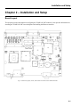
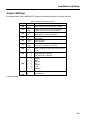
3Jumper Settings................................................................................................................................. 2-2
Switch Settings ................................................................................................................................... 2-3
Registers.............................................................................................................................................. 2-3
Front Panel Layout.............................................................................................................................. 2-5
Connectors .......................................................................................................................................... 2-6
COM1 and COM4 (J4) Pin Definitions............................................................................................... 2-10
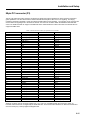
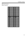
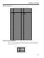
purpose.VMEbus P2 Connector ......................................................................................................... 2-12
VMEbus P2 Connector........................................................................................................................ 2-13
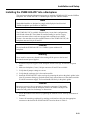
Installing the XVME 689-VR7 into a Backplane ............................................................................. 2-18
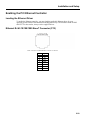
Enabling the PCI Ethernet Controller ............................................................................................... 2-20
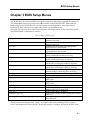
Chapter 3 BIOS Setup Menus............................................................................................... 3-1
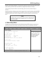
3.1 Main Setup Menu.......................................................................................................................... 3-2
3.2 Exit Menu ..................................................................................................................................... 3-4
3.3 System Boot Menu........................................................................................................................ 3-5
3.4 POST Memory Tests..................................................................................................................... 3-9
3.5 Plug and Play Configuration Menu............................................................................................. 3-12
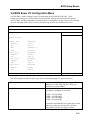
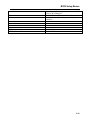
3.6 BIOS Super I/O Configuration Menu ......................................................................................... 3-15
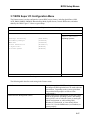
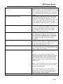
3.7 BIOS Super I/O Configuration Menu ......................................................................................... 3-17
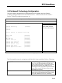
3.8 Firmbase® Technology Configuration ....................................................................................... 3-19
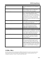
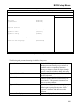
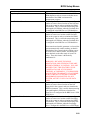
3.9 Misc. Menu ................................................................................................................................. 3-20
3.10 VMEbus Master ........................................................................................................................ 3-24
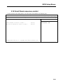
3.12 Front Panel resources control.................................................................................................... 3-28
Chapter 4 Programming........................................................................................................ 4-1
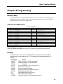
Memory Map ...................................................................................................................................... 4-1
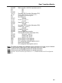
I/O Map............................................................................................................................................... 4-1
IRQ Map ............................................................................................................................................. 4-3
v