1
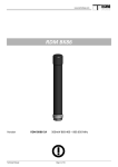
HiRes IV/Plus
User Manual
April 2005
Copyright 2005 DTA s.r.l.
All rights reserved. The reproduction of any part of this manual is allowed only with the written
authorization by DTA s.r.l..
The contents of this manual may be subject to changes without any warning.
DTA are not responsible for errors that may occur in this manual.
Revision 1.0 dated 04/04/2005
2
-
CONTENTS
INTRODUCTION
PERSONAL COMPUTER MINIMUM REQUIREMENTS
PERSONAL COMPUTER RECOMMENDED REQUIREMENTS
SCHEME OF THE INSTALLATION PROCEDURE
CONNECTING THE FDL INTERFACE CARD TO THE PC
LIBRARY & FDL-PCI INSTALLATION
WINDOWS 98
WINDOWS ME
WINDOWS 2000
WINDOWS XP
LINUX
WINDRIVER REGISTRATION
CONNECTING THE HIRES CONTROLLER TO THE PC
CONNECTING THE HIRES HEAD TO THE HIRES CONTROLLER
DESCRIPTION OF THE HIRES PLATFORM FRONT PANEL
DETAIL OF FRONT PANEL CONNECTORS
9-PIN CONNECTOR
15-PIN AD CONNECTOR
SCSI CONNECTOR
44-PIN PARALLEL CONNECTOR
26-PIN USER PORT CONNECTOR
HRIV PLUS CONTROLLER LIQUID FILLING
OPTICAL WINDOW CLEANING
SPECIFICATIONS
INDEX
4
5
5
6
7
8
11
12
15
16
18
22
22
23
25
26
27
28
29
30
31
33
3
INTRODUCTION
HiRes is a cooled digital cameras series born to detect extremely faint light emissions.
There are two versions: the standard HiRes IV and the upgraded model HiRes IV Plus, both of them made
of two main components: the head (with CCD, Double stage Peltier cooling system, electronics) and the
controller, that includes the power supply.
This series displays KODAK and E2V Technologies sensors, either marked by high definition (small
pixels: ≤ 16 µm) or high sensitivity (bigger pixels: ≥ 20 µm). They belong to the front-illuminated kind, with
thin indium electrodes able to raise the Quantum Efficiency in the case of shorter wavelengths, or to the
back-illuminated type to make the most of the latest CCD technology.
Among the main application fields: Biology, Astronomy, Spectroscopy, RAMAN Spectroscopy,
Semiconductor Physics, Plasma Physics and X-Ray Physics. A line completely devoted to Spectroscopy is
available.
HiRes IV also includes the former Hurricane specs.
HiRes IV (standard)
For the standard HiRes IV cameras we
have appealed to sophisticated sampling
and amplification techniques as well as to a
16-bit A/D Converter, to be fully exploited
in their dynamics. Furthermore, the Double
Stage Peltier cooling system allows to
perform ∆T= -50 ºC. All cameras have
been equipped with integrated peripherals,
such as parallel ports and timers, allowing
one to carry out a complete automation of
one’s experiment.
HiRes IV Plus
The HiRes IV Plus is the upgraded model of
HiRes IV. It is equipped of three integrated
peripherals, able to run an MCP, a LASER or
other external devices. Moreover, it performs a
better readout speed of HiRes IV, up to 1
Mpixel/second, and higher ∆T below ambient
temperature, due to two different system cooling:
1) Double Stage Peltier with an air exchanger,
performing ∆T= -60 ºC;
2) Double Stage Peltier with a liquid exchanger
(a glycol solution), performing ∆T= -80 ºC.
The liquid exchanger is directly connected to the freezer box, placed within the controller. The sensor cell is
vacuum tight and contains a gas (Nitrogen), so that the customer doesn't need to keep a steady maintenance.
The camera system consists of the HEAD, containing the CCD sensor, and the CONTROLLER, containing
the power supply and the freezer box.
4
-
PERSONAL COMPUTER MINIMUM REQUIREMENTS
•
CPU Pentium III 1 GHz .
•
256 Mb of RAM.
•
Microsoft Windows 98, ME, 2000, XP or LINUX (we tested the SuSE LINUX 9.0 version)
•
PCI bus compliant 2.1.
PERSONAL COMPUTER RECOMMENDED REQUIREMENTS
• CPU Pentium IV 2 GHz or higher.
• 512 Mb RAM.
• Colour monitor 19”.
5
SCHEME OF THE INSTALLATION PROCEDURE
When you use the camera for the first time, you must install the library and the FDL-PCI interface. For this
purpose, please follow the procedure described in the next pages and schematized in the diagram below:
Turn the PC off
Insert the FDL-PCI interface in the proper SLOT
Turn the PC on
LINUX
Let install the DRIVER
WINDOWS
WINDOWS OS ask to you the DRIVER:
specify the directory within the provided
CD.
Let install ViSTA software
Verify the configuration of the camera
with CAMERA SELECT option
6
-
CONNECTING THE FDL INTERFACE CARD TO THE PC
To install your FDL interface card, do as follow :
⇒ Turn your PC off, including any peripheral.
⇒ Remove the external case of the PC ( please see the relevant instructions in the PC Handbook).
⇒ Choose a free PCI expansion slot. Remove the relevant back cover by means of a screwdriver.
⇒ Insert the camera interface card into the expansion slot. Please make sure that the card is properly and
fast inserted. Fix the card by screwing the relevant screw again.
⇒ Reassemble the PC case.
Turn the PC on once again. The interface card installation has been completed.
FDL-PCI interface card
In case of a fiber optic link connection, a dedicated FDL-PCI is provided with the proper connectors.
7
LIBRARY & FDL-PCI INSTALLATION
The installation of the library is always linked to the installation of the camera, of course. For this purpose
you just need to install the PCI interface as well.
Let’s analyse the sequence of operations to be carried out according to the different Operating Systems.
Once you turn the system on for the first time with the FDL-PCI interface on, you will be asked to specify
where the available drivers are. Follow the steps on the basis of your Operative System.
WINDOWS 98
(Any window refers to the OS written in ITALIAN. The charts next to the images correspond to the
explanatory notes translated into ENGLISH)
1) Insert the FDL-PCI card in the slot of the motherboard and turn the PC on. The PC will automatically find
the FDL-PCI card and open a window like the one shown below. Click on "Next" to continue the
installation
Helped installation of the new hardware.
New drivers will be
looked for :
PCI Input Controller
A peripheral driver
is a program that
allows an hardware
peripheral to work
properly.
NEXT
CANCEL
8
-
2) The PC will have to look for the most suitable driver to the peripheral and ask if you'd rather do so
authomatically or choose it from a list of available drivers. Choose the option "Find the most suitable
driver to the peripheral (recommendable choice)" and then click on "Next".
Helped installation of the new hardware.
Choose the operation
to be carried out.
Look for the most
suitable driver to the
peripheral
(recommendable
choice)
NEXT
CANCEL
BACK
3) The PC will have to look for the most suitable driver to the peripheral and ask if you'd rather do so
automatically or choose it from a list of available drivers. Choose the option "Find the most suitable
driver to the peripheral (recommendable choice)" and then click on "Next"
Helped installation of the new hardware.
A search of the new
drivers will be
carried out in the
driver database in
the hard disc as well
as in the following
selected paths. Click
on “Next” to start the
search.
BROWSE
NEXT
Specify a path
CANCEL
BACK
9
4) As soon as the PC finds the suitable driver, a window will appear like the one shown below. Click on
"Next" to continue the installation.
Helped installation of the new hardware.
Search of the driver
file
for
the
peripheral :
You can install the
most suitable driver
to this peripheral.
Click on “Back” to
select a different
driver or, on “Next”
to continue.
NEXT
CANCEL
Driver path:
BACK
5) As soon as the copy of the files is carried out, a window will appear : it is the evidence that the installation
of the drivers necessary for the proper functioning has taken place. Click on "Finish" to end the
installation.
Helped installation of the new hardware.
FDL-PCI
Installation of the
necessary software
for
the
new
hardware peripheral
being ended.
FINISH
CANCEL
10
-
WINDOWS ME
(Any window refers to the OS written in ITALIAN. The charts next to the images correspond to the
explanatory notes translated into ENGLISH)
1) Insert the FDL-PCI card into the slot of the motherboard and turn the PC on.
As soon as the system gets started, the PC will update the driver database and then a window (like the one
shown below) will appear. Insert the "ViSTA" CD into the CD-ROM reader, wait a few seconds to allow
the reading of the CD. Then click on "Next".
Helped installation of the new hardware.
The following new hardware peripheral has been founded
Windows can look for
and install the
software able to
support the hardware
peripheral. If an
installation support
was given together
with the hardware
peripheral, please
insert it and click on
“Next”.
NEXT
CANCEL
Choose the operation
to be carried out
2) The PC will start to look for the most suitable driver to be copied onto the hard disc. Once this operation is
over, a window like the one shown below) will appear. Click on "Finish" to end the installation.
Helped installation of the new hardware.
Install the new hardware
peripheral being ended
FINISH
11
WINDOWS 2000
(Any window refers to the OS written in ITALIAN. The charts next to the images correspond to the
explanatory notes translated into ENGLISH)
1) Insert the FDL-PCI card into the slot of the motherboard and turn the PC on.
The PC will automatically find the FDL-PCI card and open a window like the one you can see below.
Click on “NEXT” to go on with the installation.
Helped installation of the new hardware.
This helped procedure allows one to
install a driver of an hardware
peripheral.
To continue, click on “Next”.
NEXT
CANCEL
2) The PC will look for the most suitable driver to the peripheral; it will ask if we prefer look for it by default
or if we’d rather choose the driver among a list of available drivers. We recommend you to select “LOOK
FOR THE DRIVER SUITABLE TO THE PERIPHERAL (RECOMMENDED)” and then press “NEXT”.
Helped installation of the new hardware.
Install driver hardware peripheral.
Click on “Next”
to identify the
driver files and
complete
the
installation.
A peripheral driver is a
program that enables the
functioning of an hardware
peripheral in an OS.
Choose
the
operation to be
carried out.
This helped procedure
allows one to complete the
installation of the
peripheral :
Look for a
suitable driver
to the peripheral
(recommended)
Visualize a list
of well-known
drivers to this
peripheral, able
to choose a
specific driver.
PCI input peripheral.
For the new peripheral,
driver files are asked. A
peripheral driver is an
application that allows the
functioning of the
hardware peripheral.
BACK
12
NEXT
CANCEL
-
3) Please insert the “ViSTA” CD and close “QUICK INSTALL” menu in case it gets opened due to the CD
autorun. Then specify where the PC has to look for the driver.
Select the CD-ROM reader and specify the following path : D:\FDL_PCI_driver (D: is the letter with
whom the CD-ROM reader is identified). Then press “NEXT”.
Helped installation of the new hardware.
Identify driver file.
Digit the driver file path.
Click on “Next”
to start the
search. If you
carry it out by a
floppy disc or a
CD-ROM,
insert one of
them
before
choosing
“Next”
Optional
searching paths
Search of the driver files
for
the
following
hardware peripheral :
PCI input peripheral.
A search of the suitable
drivers will be carried
out in the driver database
present at the PC as well
as at the optional
searching paths herewith
specified.
Floppy unit
CD-ROM unit
Specify a path
BACK
CANCEL
NEXT
4) As soon as the PC finds the right driver, a window will appear (the same as the one shown below). Click
on “NEXT” to continue the installation.
Helped installation of the new hardware.
Outcomes of the file driver search.
The helped procedure
has finished the search
of the driver files for the
hardware peripheral.
The peripheral driver
that has been found is
the following one :
PCI input peripheral
A driver for this
peripheral has been
found out. Click on
“Next” to install the
driver.
NEXT
CANCEL
e:\……………
BACK
13
5) When the PC ends to copy any file, a window appears as a confirmation of the performed installation of
the drivers necessary for the proper functioning. Choose “FINISH” to end the installation.
Helped installation of the new hardware
Finishing of the helped installation of the new hardware under progress.
Installation of the peripheral software
completed.
To end the helped procedure, click on
“Finish”.
FINISH
14
-
WINDOWS XP
(Any window refers to the OS written in ITALIAN. The charts next to the images correspond to the
explanatory notes translated into ENGLISH)correspond to the explanatory notes translated into ENGLISH)
1) Insert the FDL-PCI card into the slot of the motherboard and turn the PC on. As soon as the system gets
started, a window (like the one shown below) will appear. Insert the "ViSTA" CD into the CD-ROM
reader, close the "Quick Install" - it may open due to the CD autorun - . Select the option "Install the
software automatically (recommendable choice)". Then click on "Next" to continue the installation.
Helped installation of the new hardware
This helped procedure
allows one to install the
suitable software to :
PCI input peripheral
If the peripheral is
provided with a CD or
an installation floppy
disc, insert it in the
proper unit.
Choose one of the
following options :
Install the
software
automatically
(recommendable choice)
Install by taking it from
a list or a specific path
(for experienced users).
NEXT
CANCEL
2) The PC will start to search for the most suitable driver to the peripheral. As soon as it finds it, a window
(like the one shown below) will appear. Click on "Finish" to end the installation.
Finishing of the new helped hardware
installation in progress.
Software installation completed for :
To close the helped installation, choose
“End”
FINISH
15
LINUX
System Requirements
•
•
•
Linux 2.0.31 or higher (can be embedded Linux or Linux 2.4x)
An x86 processor.
Any 32-bit development environment supporting C (such as GCC).
Installation
1.
Insert the DTA SDK CD into your Linux machine CD drive or copy the downloaded file to your
preferred directory.
2.
Change directory to your preferred installation directory (your home directory, for example):
/$ cd ~
3.
Extract the file WDxxxLN.tgz (where xxx is the version number):
~$ tar xvzf /<file location>/WDxxxLN.tgz
For example:
o From a CD:
o
~$ tar xvzf /mnt/cdrom/LINUX/WDxxxLN.tgz
From a downloaded file:
~$ tar xvzf /home/username/WDxxxLN.tgz
4.
Change directory to WinDriver (this directory gets created by tar):
~$ cd WinDriver/
NOTE:
From version 5.x and above this directory gets created by tar, but in versions preceding 5.x the
WinDriver directory does not get created by the extraction. Therefore, when working with versions
preceding 5.x (version 4.33, for example) first create a directory (e.g., WinDriver) before proceeding
with the installation.
(/$ mkdir ~/WinDriver)
5.
Install WinDriver:
a. ~/WinDriver$ make
b. Become super user:
~/WinDriver$ su
c. Install the driver:
~/WinDriver# make install
16
-
6.
Create a symbolic link so that you can easily launch the DriverWizard GUI
~/WinDriver$ ln -s ~/WinDriver/wizard/wdwizard/ usr/bin/wdwizard
7.
Change the read and execute permissions on the file wdwizard so that ordinary users can access this
program.
8.
Change the user and group ids and give read/write permissions to the device file /dev/windrvr6
depending on how you wish to allow users to access hardware through the device.
9.
You can now start using WinDriver to access your hardware and generate your driver code!
Restricting Hardware Access on Linux
CAUTION:
Since /dev/windrvr6 gives direct hardware access to user programs, it may compromise kernel stability on
multi-user Linux systems. Please restrict access to the DriverWizard and the device file /dev/windrvr6 to
trusted users.
For security reasons the WinDriver installation script does not automatically perform the steps of changing
the permissions on /dev/windrvr6 and the DriverWizard executable (wdwizard).
17
WINDRIVER REGISTRATION
1) After the installation of the drivers for the FDL-PCI card, we need to record the files to make them work
properly. Insert the "ViSTA" CD into the CD-ROM reader, wait a few seconds so as to allow the PC to
load the "QUICK INSTALL" menu.
2) Once the PC has loaded the "QUICK INSTALL" menu, click on "VISTA". The PC will start the
installation of the necessary drivers by loading a window like the one shown below.
Once you have installed the drivers and the "ViSTA" software, restart the PC as on demand.
With reference to WINDOWS 2000 and WINDOWS XP OS, please go on up to point 3, while to point 6 as
far as any other OS is concerned.
18
-
3) Once the restart has been performed, the PC will inform you - by a window like the one shown
below - that no digital signature was found for this software. Click on "Yes" to continue the copy
of the files.
Digital segnature not found
Microsoft
digital
signature marks the
software tested under
Windows; it guarantees
the software from being
modified
after
any
performed test.
In order to look
for the software
with Microsoft
digital
signature, click
on the Update
Windows Web
at
….(information
provided
in
English)
to
verify
its
availability.
The software that is
going to be installed
does
not
include
Microsoft
digital
signature. So the proper
functioning
of
the
software under Windows
is not guaranteed.
Will you
continue the
installation ?
WinDriver
YES
4) The PC will ask you to insert the disc labelled "JUNGO INSTALLATION DISC"; insert the "ViSTA" CD
and click on "OK".
Insert the Disc
Insert the compact disc
labelled “Jungo
Installation Disc” into
the CD-ROM(E:) unit,
then choose OK.
Select OK to copy a
file from a different
origin (like a floppy or
a web server) too.
CANCEL
19
5) After having pressed "OK", the PC will ask (by opening the A window) where the original file is located.
Click on "Browse"; the B window will open : please check if the open folder is D:\FDL_PCI_DRIVER (D
represents the letter with whom the CD-ROM reader is being identified). Select the windrvr6.sys, then click
on "Open". If the C window appears, click on "OK" and the PC will automatically finish the copy of the
files.
A
B
C
6) Once you have finished to install the necessary drivers for the FDL-PCI card and WINDRIVER, check
the correct installation of the two peripherals.
When you use WINDOWS 98 and WINDOWS ME, you have to click on "COMPUTER RESOURCES" by
means of the right key of the mouse. A menu with different options will open; click on "PROPERTIES" by
means of the left key of the mouse. A window with different sections will open; click on "PERIPHERAL
MANAGEMENT" and check if the two peripherals have been installed correctly (see the image below).
When you use WINDOWS 2000 and WINDOWS XP, you have to click on "COMPUTER RESOURCES"
by means of the right key of the mouse. A menu with different options will open; click on "PROPERTIES"
by means of the left key of the mouse. A window with different sections will open; click on "HARDWARE"
and then on "PERIPHERAL MANAGEMENT". Then check if the two peripherals have been installed
correctly (see the image below)
20
-
GENERAL
PERIPHERAL
MANAGEMENT
HARDWARE
PROFILES
PERFORMANCES
PROPERTIES
UPDATE
REMOVE
CANCEL
PRINT
The tests have been carried out with the following OS:
WINDOWS 98 SECOND EDITION
WINDOWS 2000 WITHOUT SERVICE PACK
WINDOWS 2000 WITH SERVICE PACK 3
WINDOWS ME
WINDOWS XP WITHOUT SERVICE PACK
WINDOWS XP WITH SERVICE PACK 1
21
CONNECTING THE HiRes CONTROLLER TO THE PC
The connection procedure is common both for the standard HR IV and the HR IV Plus cameras.
To install your hardware platform on the PC interface, follow the following steps:
Before making any connection, make sure that the PC and every peripheral are switched OFF and the
HR IV is not powered!
⇒ Connect the parallel cable (supplied with a standard length of 2,5 mt) to the “parallel” port on the HR IV
front panel and to the interface card FDL-PCI previously mounted on PC.
⇒ In case you have purchased the model with FOL connectors for the serial connection on optic fiber,
insert an end of an optic fiber cable into the TX connector of the HR IV and the other one into the RX
connector of the FDL-PCI, then insert an end of an optic fiber cable into the RX connector of the HR IV
and the other one into the TX connector of the FDL-PCI.
NOTE: the two vitric optic fiber cables, mod. 62/125, are optional and a length up to 4 Km is available
upon request.
Warning: once the platform has been installed,
make sure there are at least 2 cm of
clear space behind the cooling fan
(showed by the red arrow in the
figure on the right), so that this can
efficiently work.
CONNECTING THE HIRES HEAD TO THE HIRES CONTROLLER
Before making any connection, make sure that the HR IV is not powered!
⇒ Connect an end of the SCSI cable (supplied with the CCD camera) to the relevant connector on the
HRIV front panel, then connect the other end to the SCSI connector of the CCD camera.
NOTE: the 64-pin connectors are only SCSI type, the communication protocol being used is not
SCSI!
⇒ Connect an end of the 9-pole cable (supplied with the CCD camera) to the relevant connector above the
SCSI port of the HR IV front panel, then connect the other end to the relevant connector on the CCD
camera.
22
-
DESCRIPTION OF THE HIRES PLATFORM FRONT PANEL
HR IV Front Panel
HR IVPlus Front Panel
On the HR IV and HR IV Plus platform front panel are the connectors for its connection to the CCD Camera
and the PC. Also, there are 4 red LED’s that allow you to read the device status at any moment.
NOTE:
On the HR IV Plus platform front panel there are even the cooling system input/output gumplates (IN/OUT)
and the fiber optic link connectors (TO-PARALLEL, TX, RX), described in a proper manual
23
Here below the description of the connectors common to the HR IV and HR IV Plus platform front panel.
Starting from the top part on the left, you can see the following connectors:
•
•
•
•
•
9-pin connector for the control of the Peltier, the shutter and the cooling fans of the CCD Camera.
AD: high density 15-pin connector for the connection and the communication with the auxiliary
devices such as filter wheel, image intensifier, focuser, and so on, manufactured by DTA.
SCSI type connector for the power supply and the data transfer from the CCD Camera to the
platform.
PARALLEL: high density 44-pin connector for the parallel communication at 32 bits (Hurricane) or
16 bits (HiRes) with the PC.
USER PORT: 26-pin connector which is a programmable bidirectional parallel communication port.
In the top part on the right, there are 4 red LED’s whose function is to indicate the platform status.
Starting from the LED on the left, they are:
•
•
•
•
24
POWER: if ON, this LED indicates the presence of the power supply voltage.
SELECT: if ON, indicates that the HR IV is active.
COOLER: if ON, indicates that the cooling system has been enabled.
EXPOSURE: if ON, this LED indicates that the CCD camera imaging is in progress.
-
DETAIL OF FRONT PANEL CONNECTORS
In the following paragraph, we will list the signals on the connectors’pins of the HR IV platform front panel.
9-PIN CONNECTOR
1
6
S1 (+)
F1(-)
2
7
S2 (-)
F2(+)
3
8
-
4
9
P1(-)
-
5
-
P2(+)
-
5
10
15
BD3
OUT 0
OUT 5
• S1-S2: Shutter control.
CAUTION 65 Volts !
• P1-P2: Peltier cell control, 3.15A Max.
• F1-F2: Cooling fan control, 12V 500Ma Max.
15-PIN AD CONNECTOR
1
6
11
BD7
BD2
OUT 1
2
7
12
BD6
BD1
OUT 2
3
8
13
BD5
BD0
OUT 3
4
9
14
BD4
IN 0
VDC(+12V)
• BD7-BD0: bidirectional port reserved for the manufacturer’s own use.
• IN0: input from the aux device necessary for the handshake.
• OUT3-OUT0: handshake outputs towards the aux device.
NOTE: the pins from 2 to 13 are TTL compatible.
25
SCSI CONNECTOR
1
5
9
13
17
21
25
29
33
37
41
45
49
53
57
61
65
CK-GND
CLAMP
AD-CLK
CCD-CLK
CCD-CLK
CCD-CLK
SIN0
GND
GND
D13 *
D4
S0
VDD
VSS
HIV
HIV
D11 #
•
•
•
•
•
•
•
•
•
•
•
•
•
•
•
2
6
10
14
18
22
26
30
34
38
42
46
50
54
58
62
66
CK-GND
SIGNAL
CCD-CLK
GAIN-CCD
CCD-CLK
CCD-CLK
SIN1
GND
GND
D12 *
D5
S1
VDD
VSS
HIV
D8 #
GND
3
7
11
15
19
23
27
31
35
39
43
47
51
55
59
63
67
CK-GND
STC
CCD-CLK
CCD-CLK
CCD-CLK
CCD-CLK
D0
GND
D15 *
D2
D6
VDD
VDD
VSS
HIV
D9 #
GND
4
8
12
16
20
24
28
32
36
D
44
48
52
56
60
64
68
CK-GND
AD-RES
CCD-CLK
CCD-CLK
CCD-CLK
L/H
D1
GND
D14 *
D3
D7
VDD
VSS
VSS
HIV
D10 #
GND
CK-GND: clock ground (digital).
CLAMP – SIGNAL: CDS signals.
STC: signals that instruct the AD the start of the conversion.
AD-RES: AD reset.
AD-CLK: AD clock signal.
CCD-CLK: CCD general clocks.
L/H: instructs the reading of the low (less significant 8 bits) or high part (most significant 8 bits) of
the 16 bit parallel bus.
SIN0 – SIN1: selects the input to the AD.
D0 – D15: parallel data.
GND: analog ground.
S0: serial clock.
S1: serial data.
VDD: +15V (according to the CCD sensor, this value can be modified).
VSS: -15V (according to the CCD sensor, this value can be modified).
HIV: +27V (according to the CCD sensor, this value can be modified).
NOTE
The parallel data bus is at 16 bits if the camera being mounted is a Hurricane. If the camera connected to the
HR IV platform is a HiRes, the parallel data bus is at 8 bits, therefore in this case the Di pins marked with
the * are connected to the digital ground, while those marked with the # are connected to the analog ground.
NOTE: the 5-28, 35-46 and 62-65 pins are TTL compatible.
26
-
44-PIN PARALLEL CONNECTOR
1
6
11
16
21
26
31
36
41
D0
D15
D18
D1
VCC
D19
D2
VCC
D20
2
7
12
17
22
27
32
37
42
D3
ACK
D21
D4
REQ
D22
D5
A/D
D23
3
8
13
18
23
28
33
38
43
D6
R/W
D24
D7
STB
D25
D8
GND
D26
4
9
14
19
24
29
34
39
44
D9
GND
D27
D10
GND
D28
D11
GND
D29
5
10
15
20
25
30
35
40
-
D12
GND
D30
D13
D16
D31
D14
D17
-
• D0 – D31: data, if the camera being controlled by the HR IV is a Hurricane, all the 32 given bits are
significant, otherwise in case of a HiRes only the less significant 16 bits are significant.
• REQ: by means of this pin, the platform starts the transfer request to the PC.
• ACK: response signal to the REQ signal from the PC.
• A/D: by means of this pin, it is indicated the presence of addresses or data on the bus.
• R/W: indicates whether the operation to execute is a reading or a writing.
• STB: STROBE signal.
• GND: ground.
• VCC: +5V.
NOTE: all signals are TTL compatible.
By means of this port, it is possible to carry out a parallel connection between CCD Camera and PC.
27
26-PIN USER PORT CONNECTOR
1
4
7
10
13
16
19
22
25
•
•
•
•
•
•
•
•
•
GND
TACK
RL00
GND
BD0
RL01
SHUTTER
BD1
RL10
2
5
8
11
14
17
20
23
26
SYN0
BD2
RL11
SYN1
BD3
RL20
SYN2
BD4
RL21
STC
BD5
RL30
EXTSHUT
BD6
RL31
TRG
BD7
-
BD0 – BD7: bidirectional parallel port.
SHUTTER: shutter TTL output, for the control of a second external shutter.
SYN0 – SYN2: synchronism signals for external use.
STC: signal that instructs the AD the start of the conversion.
EXTSHUT: by means of this signal, the user can directly control the shutter (by keeping it at 1 the
shutter stays open, otherwise it is closed).
TRG: bidirectional pin for the trigger signals transmission from and to the camera.
TACK: input from the camera that indicates that this has seen an input trigger signal.
GND: ground.
RL00 – RL31: by means of these pins, it is possible to control some external relays. 24 VDC, 1A
Max.
NOTE: the 2-6, 11-15 and 20-24 pins are TTL compatible.
28
3
6
9
12
15
18
21
24
-
-
HRIV PLUS CONTROLLER LIQUID FILLING:
First employment:
Open the expansion tank placed on the right external side of the controller, and fill it with the liquid
provided with the camera.
Press the START button and some other liquid comes in circle.
Take pressed the START button until the flow of the circulating liquid is constant (no more liquid is
pumped up from the tank) and then close the expansion tank.
Press again the START button and the pump remain working, because the internal pressure on the silicon
tube is constant.
The expansion tank is fixed external with two screws (M3 type), but it can be freely moved, if necessary.
To avoid inconveniences (such as liquid leakage), let move the expansion tank only before filling it.
Next applications:
Push START button for start up the pump. The START button is connected with a manostat that block
the liquid flow in case of pressure leak.
Cooling liquid composition:
The cooling liquid for HRIV Plus controller is composed by:
-
50 % distilled water;
50 % ethylene glycol.
ATTENTION:
Do not use silicone liquid.
29
OPTICAL WINDOW CLEANING
Both the optical window and the CCD cleaning are carried out in the clean room by means of a 30magnifying power microscope. This procedure removes any dust which can otherwise bring about
unmistakable marks on the image you have taken. In particular such spots increase as the focal ratio gets
wider. In other words an image may not show any mark at f/5.6 but
it can be
clearly noted at f/32 because of an obvious geometrical problem of projection.
Due to the shutter or elapsed time, the external surface of the optical window
may gather dirty particles that may be easily removed.
To perform such task we use a compressed air cylinder specifically designed for
optical cleaning.
Be careful !!! There are similar products that, instead of using compressed air,
use a liquefiable gas : at ambient pressure it quickly gassifies, thus
“triggering” an air-compressed-effect. You do not absolutely have to use these products : they may give rise
to heavy marks or rings on the windows itself.
A product we can recommend is DUST-OFF provided by EDMUND-OPTICS. Thanks to DUST-OFF (or
any other similar product) it is very easy to get rid of any microparticles : keep the shutter open for a few
seconds (by the camera control program) and spray some air blast. We kindly advise you against using
cloths, optical paper and cleaning liquids because the dirt will be only mixed up or, even worse, increased.
The risk is to finally damage the coating of the optical window itself !
30
-
SPECIFICATIONS
SHUTTER:
Electromechanical . Exposure time: from 0.01 s to 9999 s
A/D CONVERTER:
16 bit for HR IV
Selectable: 12, 14, 16 bit for HR IV Plus
SETTABLE GAINS:
2 for HR IV
64 for HR IV Plus
READ OUT SPEED:
up to 100 kpixel/s for HR IV
≥ 1 Mpixe/s for C3P
INTERFACE:
FDL-PCI 8, 16, 32 bit.
COOLING:
HR IV
• Double stage PELTIER (-50°C below ambient)
HR IV Plus
• Double stage Peltier + air stage (-60°C below ambient)
• Double stage Peltier + liquid stage (-80°C below ambient)
CCD TEMPERATURE CONTROL:
± 0.1 °C
OPTICAL WINDOW:
Fused Silica
FILTER WHEEL:
External
BACKFOCUS:
17.5 mm
MAX TOTAL NOISE:
10 eMOUNT:
According to different sensors
BINNING:
From 1 x 1 to 8 x 8 or arbitrary
POWER SUPPLY:
230V 50Hz.
MAX ABSORPTION:
250 W for HR IV
31
700 W for HR IV Plus (cooling system included)
WEIGHT:
HEAD
1.7 kg both of cameras
CONTROLLER:
8 kg for HR IV
17.5 kg for HR IV Plus
DIMENSIONS:
HEAD:
130x130x160 mm3 for HR IV
130x130x103 mm3 for HR IV Plus
CONTROLLER:
250x150x308 mm3 for HR IV
483x187x345 mm3 for HR IV Plus
32
-
INDEX
9
9-PIN CONNECTOR
22
15
15-PIN CONNECTOR
22
26
26-PIN USER PORT CONNECTOR
26
44
44-PIN PARALLEL CONNECTOR
25
C
CONNECTING THE FDL INTERFACE CARD TO THE PC
CONNECTING THE HIRES CONTROLLER TO THE PC
CONNECTING THE HIRES HEAD TO THE HIRES CONTROLLER
6
21
21
D
DESCRIPTION OF THE HIRES PLATFORM FRONT PANEL
DETAIL OF FRONT PANEL CONNECTORS
22
23
H
HRIV PLUS CONTROLLER LIQUID FILLING
29
I
INTRODUCTION
4
L
LIBRARY & FDL-PCI INSTALLATION
LINUX
7
15
O
OPTICAL WINDOW CLEANING
30
P
PERSONAL COMPUTER MINIMUM REQUIREMENTS
PERSONAL COMPUTER RECOMMENDED REQUIREMENTS
4
4
S
SCHEME OF THE INSTALLATION PROCEDURE
SCSI CONNECTOR
SPECIFICATIONS
5
24
31
W
WINDOWS 98
WINDOWS ME
WINDOWS 2000
WINDOWS XP
WINDRIVER REGISTRATION
7
10
11
14
17
33
s.r.l.
Viale Campania 23
56021 Cascina (Pisa) - ITALY
web site: www.dta.it
e-mail: [email protected]
34